Trane Tsc060 120 Users Manual RT PRC016 EN 10/03
TSC060-120 to the manual 52a69b63-1336-443c-afbe-a8f81fa95f07
2015-01-21
: Trane Trane-Tsc060-120-Users-Manual-236161 trane-tsc060-120-users-manual-236161 trane pdf
Open the PDF directly: View PDF ![]() .
.
Page Count: 48
Packaged Cooling with
Electric Heat Rooftop Units
Precedent™
TSC060-120
50 Hz
RT-PRC016-EN
February 2004
© 2004 American Standard Inc. All rights reserved RT-PRC016-EN
Introduction
Precedent™ . . . The same Trane quality...
with added flexibility. Precedent is a
flexible line of packaged units that covers
a wide variety of applications.
ReliaTel™ microprocessor controls
provide superior flexibility for the
simplest to the most sophisticated
applications. In addition to controls,
Precedent offers many other outstanding
features and option choices.
With its sleek compact cabinet, rounded
corners and beveled top, it may just be
the most aesthetically pleasing packaged
unit on the planet. And, of course,
Precedent carries the Trane reputation
for excellence, quality and reliability.
It’s
hard to stop a Trane
.
From simple applications, to the most
complex, Precedent has the solution.
4RT-PRC016-EN
Features and
Benefits
Unit Cabinet
The compact cabinet with rounded
corners takes up less room and is less
costly to ship. The beveled and ribbed
top is not only aesthetically pleasing, it is
designed to prevent water from pooling.
Single Point Power
A single electrical connection powers the
unit.
Compressors
Precedent™ contains the best
compressor technology available to
achieve the highest possible
performance. Our compressor line
includes Trane built reciprocating and
scrolls.
Easy Access Panels
Easy access panels reduce the number of
possible water entry points.
Low Ambient Cooling
All Precedent units have cooling
capabilities down to 0°F as standard.
Unit Base
For added water integrity, Precedent has
a raised 29 mm (1
1/8") lip around the
unit’s downflow supply and return to
prevent water from blowing into the
ductwork.
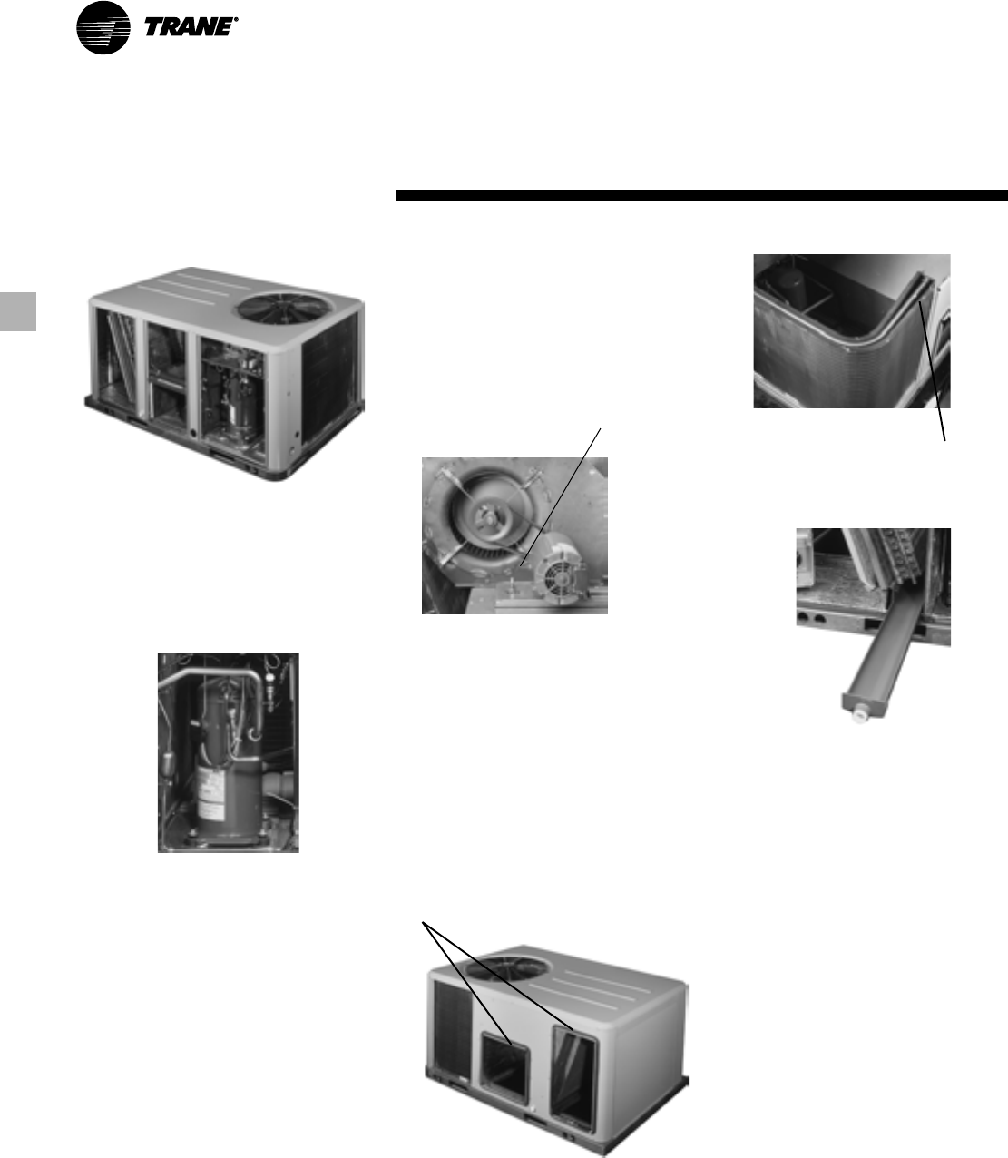
Sloped Drain Pans
Every Precedent unit has a non-
corrosive, removable, double-sloped
drain pan that’s easy to clean and
reversible to allow installation of drain
trap on either side of the unit.
Through the Base Condensate
Every unit includes provisions for
through the base condensate drain
connections. This allows the drain to be
connected through the roof curb instead
of a roof penetration.
Foil-Faced Insulation
All panels in the Evaporator section of
the unit have cleanable foil-faced
insulation. All edges are either captured
or sealed to ensure no fibers get into the
airstream.
Convertible Units
•The units ship in a downflow
configuration. They can be easily
converted to horizontal by simply
moving two panels.
•Units come complete with horizontal
duct flanges so the contractor doesn’t
have to field fabricate them. These
duct flanges are a time and cost saver.
Easy Access Panels
Remove two screws for access to the
standardized internal components and
wiring.
Easy-Adjust Idler Arm
With the Easy-Adjust Idler Arm, the belt
and sheaves can be quickly adjusted
without moving the mounted fan motor.
The result is a major savings in time and
money. Patented Condenser Coil
Precedent boasts a patented 1+1+1
Hybrid coil, permanently gapped for
easy of cleaning.
Colored And Numbered Wiring
You save time and money tracing wires
and diagnosing the unit.
5
RT-PRC016-EN
Features and
Benefits
Flexible Applications
• Only two roof curbs for the 5-10 ton
Precedent line. . .simplifies curb
selection.
•ReliaTel microprocessor controls to
meet either the simple or the more
complex application.
• Airflow is outstanding. The Precedent
can replace an older machine with old
ductwork and, in many cases, improve
comfort through better air distribution.
• Belt drive — standard or oversized
supply fan motors meet a wide airflow
range.
• Precedent offers ultimate flexibility.
Options and components are not pre-
packaged at the factory. Units are built
to order in our standard “shortest in
the industry” ship cycle time.
Standardized Components
•Components are placed in the same
location on all Precedent™ units.
Familiarize yourself with one Precedent
and you are familiar with every
Precedent.
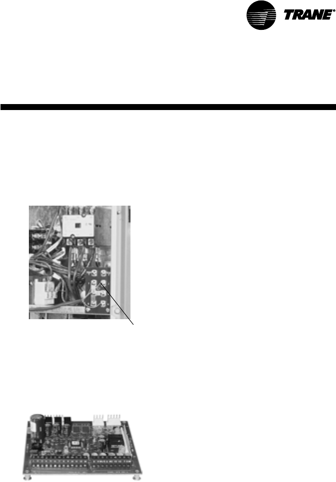
Easy Access Low Voltage Terminal
Board
Precedent’s Low Voltage Terminal Board
is external to the electrical control
cabinet. It is extremely easy to locate and
attach the thermostat wire. This is
another cost and time saving installation
feature.
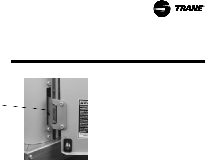
Low Voltage Connections
The wiring of the low voltage
connections to the unit and the zone
sensors is as simple as 1-1, 2-2, and 3-3.
This simplified system makes it easy for
the installer to wire
Single-Side Service
Single-side service is standard on all
Precedent units.
6RT-PRC016-EN
Features and
Benefits
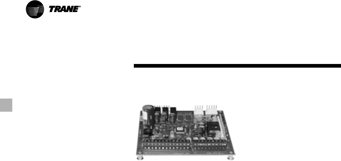
Micro Controls
Several years ago, Trane was the first to
introduce microprocessor controls into
the Light Commercial Market. That
design, along with immeasurable
experience, has provided the
technology for Trane’s second-
generation ReliaTel™ microprocessor
controls.
ReliaTel™ Micro:
• Provides unit control for heating,
cooling, and ventilating by utilizing
input from sensors that measure
outdoor and indoor temperature.
• Improves quality and reliability
through the use of time-tested
microprocessor controls and logic.
• Prevents the unit from short cycling,
considerably improving compressor
life.
• Ensures that the compressor will run
for a specific amount of time, which
allows oil to return for better
lubrication, enhancing the reliability of
the compressor.
• Reduces the number of components
required to operate the unit, thereby
reducing possibilities for component
failure.
• Eliminates the need for field-installed
components with its built-in anti-
short-cycle timer, time delay relay
and minimum ‘’on’’ time controls.
These controls are factory tested to
assure proper operation.
• Requires no special tools to run the
Precedent unit through its paces
during testing. Simply place a
jumper between Test 1 and Test 2
terminals on the Low Voltage
Terminal Board and the unit will walk
through its operational steps. The
unit automatically returns control to
the zone sensor after stepping
through the test mode a single time,
even if the jumper is left on the unit.
• As long as the unit has power and
the LED is lit, the Micro is
operational. The light indicates that
the Micro is functioning properly.
• Features expanded diagnostic
capabilities when used with Trane’s
Integrated Comfort ™ Systems.
• As an energy benefit, softens
electrical ‘’spikes’’ by staging on fans,
compressors and heaters.
• The Intelligent Fallback or Adaptive
Control is a benefit to the building
occupant. If a component goes
astray, the unit will continue to
operate at predetermined
temperature set points.
• Intelligent Anticipation is a standard
feature of the Micro. Functioning
constantly, the Micro and zone
sensors work together in harmony,
to provide tight comfort control.
7
RT-PRC016-EN
Features and
Benefits
Factory-installed Options
Hinged Access Doors
These doors permit easy access to the
filter, fan/heat, and compressor/control
sections. They reduce the potential roof
damage from screws or sharp access
door corners.
Economizer
Equipped with either dry bulb, reference
or comparative enthalpy sensing, this
feature provides free cooling as the
outdoor temperature and/or humidity
decreases. Economizers, correctly
installed, offer a valuable energy
savings. Factory-installed economizers
save time and ensure proper installation.
Phase Monitor
Phase monitor shall provide 100%
protection for motors and compressors
against problems caused by phase loss,
phase imbalance, and phase reversal.
Phase monitor is equipped with an LED
that provides an ON or FAULT indicator.
Clogged Filter/Fan Fail Switches
These sensors allow a zone sensor
service light or Integrated Comfort
System to indicate a dirty filter or a fan
that’s not working. The field installation
charges for these valuable feedback
devices often eliminate them from
consideration. Factory installation can
make such features a good investment.
Comm-3/4 Trane Communication
Interface
Available factory or field-installed. This
module when applied with ReliaTel™
easily interfaces with Trane’s Integrated
Comfort™ System.
The following options round-out the
complete line of Precedent™ options:
— 0 - 50% Manual or Motorized
Outside Air
— Hail Protection Quality Coil Guards
— Electric Heaters (available as field
installed accessories)
— Discharge Air Sensor
— Wide array of Zone Sensors and
Thermostats
— Factory built Roof Curb
One of Our Finest Assets:
Trane Sales Representatives are a
Support group that can assist you with:
— Product
— Application
— Service
— Training
— Special Applications
— Specifications
— Computer Programs and much more
Precedent has the features and benefits
that make it first class in the light
commercial rooftop market. Designed
with input from field contractors and
engineers, its airflow performance is
outstanding.
Precedent…The same Trane
quality…with added flexibility.
8RT-PRC016-EN
Features and
Benefits
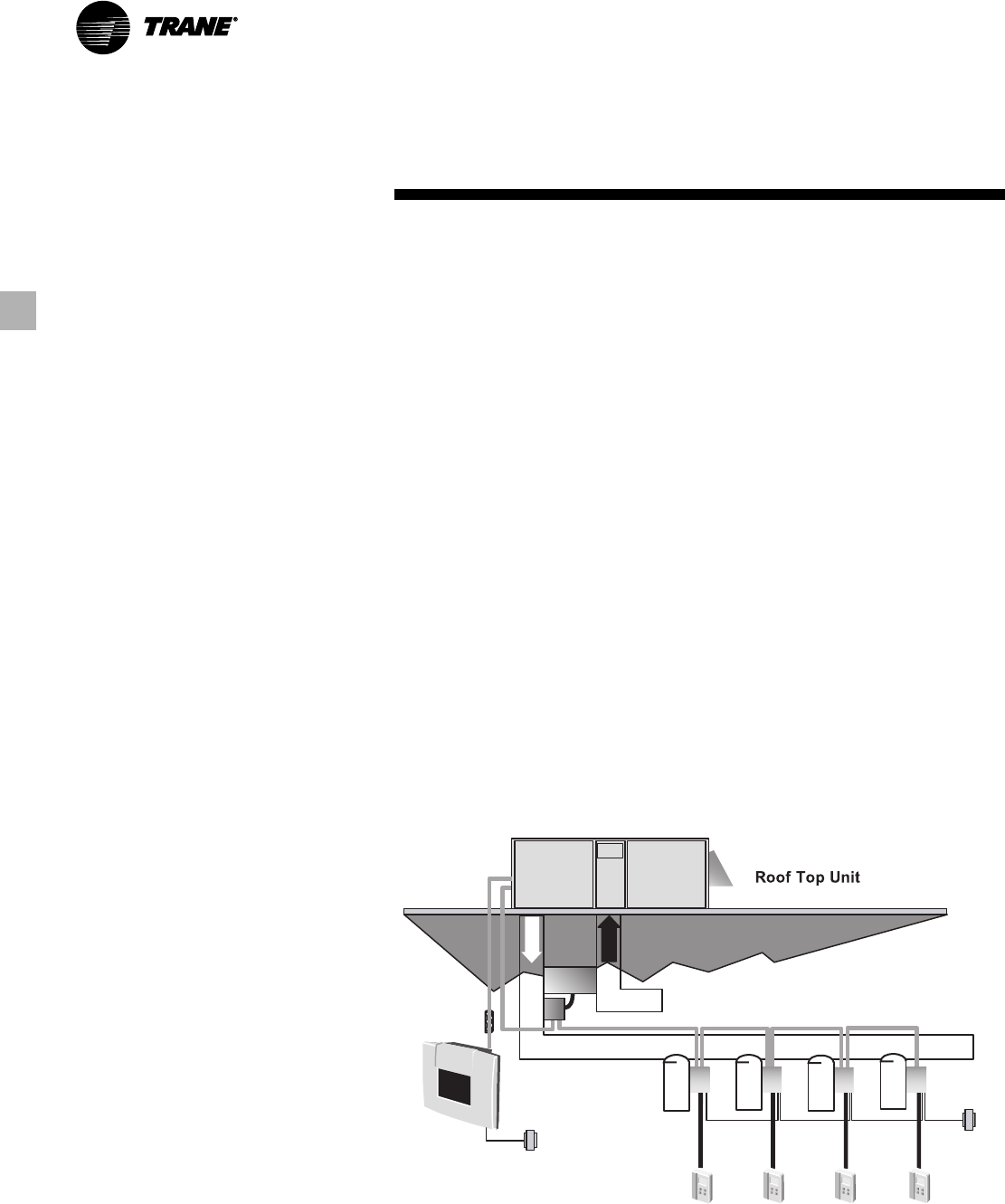
VariTrac
When Trane’s changeover VAV System
for light commercial applications is
coupled with Precedent, it provides the
latest in technological advances for
comfort management systems and can
allow thermostat control in every zone
served by VariTrac.
• We perform a 100% coil leak test at the
factory. The evaporator and condenser
coils are leak tested at 1375 kPa (200
psig) and pressure tested to 3100 kPa
(450 psig).
• All parts are inspected at the point of
final assembly. Sub-standard parts are
identified and rejected immediately.
• Every unit receives a 100% unit run test
before leaving the production line to
make sure it lives up to rigorous Trane
requirements.
We test designs at our factory not on
our customers!
Quality And Reliability Testing
•All Precedent™ designs were rigorously
rain tested at the factory to ensure
water integrity.
• Actual shipping tests were performed
to determine packaging requirements.
Units were test shipped around the
country to determine the best
packaging.
• Factory shake and drop tests were
used as part of the package design
process to help assure that the unit
arrives at the job site in top condition.
• Rigging tests include lifting a unit into
the air and letting it drop one foot,
assuring that the lifting lugs and rails
hold up under stress.
VariTrac™
9
RT-PRC016-EN
Application of this product should be
within the cataloged airflow and cooling
considerations.
Low Ambient Cooling
The Precedent™ line features, with
ReliaTel™ microprocessor controls, low
ambient cooling down to 18°C (0°F).
Contact your local Trane Representative
for more assistance with low ambient
cooling applications.
Barometric Relief
This product line offers an optional
barometric relief damper. for use in
conjunction with economizer option.
This accessory consists of gravity
dampers which open with increased
pressure. As the building air pressure
increases, the pressure in the unit return
air section also increases, opening the
dampers and relieving the conditioned
space.
NOTE: THE EFFECTIVENESS OF
BAROMETRIC RELIEF DAMPER
DURING ECONOMIZING OPERATION
IS SYSTEM RELATED.
PRESSURE DROP OF THE RETURN AIR
SYSTEM SHOULD BE CONSIDERED TO
CONTROL BUILDING PRESSURIZA-
TION.
Condensate Trap
The evaporator is a draw-thru
configuration. A trap must be field
provided prior to start-up on the cooling
cycle.
Clearance Requirements
The recommended clearances identified
with unit dimensions should be
maintained to assure adequate service
maximum capacity and peak operating
efficiency. Actual clearances which
appear inadequate should be reviewed
with the local Trane sales personnel.
Unit Pitch
These units have reversible sloped
condensate drain pans. Units must be
installed level, any unit slope must be
toward the side of unit where
condensate drain is connected.
Application
Considerations
10 RT-PRC016-EN
Cooling Capacity
Step 1
Calculate the building’s total and sensible
cooling loads at design conditions. Use
the Trane calculation methods or any
other standard accepted method.
Factors used in unit selection:
A
Total Cooling Load: 16.7 kW
B
Sensible Cooling Load: 11.7 kW
C
Airflow: 3400 m3/h
D
Electrical Characteristics: 380-415/50/3
E
Summer Design Conditions: Entering
Evaporator Coil: 27 DB, 19 WB Outdoor
Ambient: 35
F
External Static Pressure: 110 Pa
Step 2
Table PD-1 shows that a TSC060AD has a
gross cooling capacity of 17.8 kW and
14.4 kW sensible capacity at 3400 m3/h
and 35 DB outdoor ambient with 27 DB,
19 WB air entering the evaporator.
To Find Capacity at Intermediate
Conditions Not in the Table
When the design conditions are between
two numbers that are in the capacity
table, interpolation is required to
approximate the capacity. Note:
Extrapolation outside of the table
conditions is not recommended.
Step 3
In order to select the correct unit which
meets the building’s requirements, the
fan motor heat must be deducted from
the gross cooling capacity. The amount
of heat that the fan motor generates is
dependent on the effort by the motor -
cfm and static pressure. To determine
the total unit static pressure:
External Static (duct system)
110 Pa
Standard Filter 1 in. 37 Pa
from Table PD-21
Economizer 5 Pa
(100% Return Air) from
Table PD-21
Electric Heater Size 7.5 kW 17 Pa
from Table PD-21
Total Static Pressure 169 Pa
Note: The Evaporator Fan Performance
Table PD-6 has deducted the pressure
drop for a 25 mm filter already in the
unit (see note below Table PD-6).
Therefore, the actual total static pressure
is 169-17 (from Table PD-21) = 152 Pa.
With 3400 m3/h and 152 Pa
Table PD-6 shows .67 kW for this unit.
Note below the table gives a formula to
calculate Fan Motor Heat,
Fan Motor Heat (kw) =
1.144 x (Fan kW) + 0.132
= 1.144 x 0.67 + 0.132 = 0.90 kW
Now subtract the fan motor heat from
the gross cooling capacity of the unit:
Net Total Cooling Capacity
= 17.8 kW - 0.9 = 16.9 kW.
Net Sensible Cooling Capacity
= 14.4 kW - 0.9 = 13.5 kW.
Step 4
If the performance will not meet the
required load of the building’s total or
sensible cooling load, try a selection at
the next higher size unit.
Heating Capacity
Step 1
Calculate the building heating load using
the Trane calculation form or other
standard accepted method.
Step 2
Size the system heating capacity to
match the calculated building heating
load. The following are building heating
requirements:
A
Total heating load of 5 kW
B
2000 cfm
C
380 volt/3 phase Power Supply
The electric heat accessory capacities are
listed in Table PD-23. From the table, the
smallest heater will deliver 7.5 kW at
380 V. Referring to Table ED-2, the
electric heater selection is
BAYHTRR412A.
Air Delivery Selection
External static pressure drop through the
air distribution system has been
calculated to be 110 Pa. From Table PD-
21 static pressure drop through the
economizer is 5 Pa and the 7.5 kW heater
is 17 Pa (110 + 5 + 17). Enter Table PD-6
for a TSC060AD at 3400 m3/h and 132 Pa
static pressure. The standard motor will
give the desired airflow at a rated kW of
0.64.
Accessory Selection
Select accessories needed to
accommodate the application.
Selection
Procedure - SI Units

11
RT-PRC016-EN
Selection
Procedure - IP Units
Cooling Capacity
Step 1
Calculate the building’s total and sensible
cooling loads at design conditions. Use
the Trane calculation methods or any
other standard accepted method.
Factors used in unit selection:
A
Total Cooling Load: 59 MBh
B
Sensible Cooling Load: 40 MBh
C
Airflow: 2000 cfm
D
Electrical Characteristics: 380-415/50/3
E
Summer Design Conditions: Entering
Evaporator Coil: 80 DB, 67 WB Outdoor
Ambient: 95
F
External Static Pressure: 0.45 in. wg
Step 2
Table PD-1a shows that a TSC060AD has
a gross cooling capacity of 62.0 MBh and
46.4 MBh sensible capacity at 2000 cfm
and 95 DB outdoor ambient with 80 DB,
67 WB air entering the evaporator.
To Find Capacity at Intermediate
Conditions Not in the Table
When the design conditions are between
two numbers that are in the capacity
table, interpolation is required to
approximate the capacity. Note:
Extrapolation outside of the table
conditions is not recommended.
Step 3
In order to select the correct unit which
meets the building’s requirements, the
fan motor heat must be deducted from
the gross cooling capacity. The amount
of heat that the fan motor generates is
dependent on the effort by the motor -
cfm and static pressure. To determine
the total unit static pressure:
External Static (duct system)
0.45 wg
Standard Filter 1 in. 0.15 wg
from Table PD-21a
Economizer 0.02 wg
(100% Return Air) from
Table PD-21a
Electric Heater Size 26 MBh 0.07 wg
from Table PD-21a
Total Static Pressure 0.69 wg
Note: The Evaporator Fan Performance
Table PD-6a has deducted the pressure
drop for a 1 in. filter already in the unit
(see note below Table PD-6a). Therefore,
the actual total static pressure is 0.69 -
0.15 (from Table PD-21a) = 0.50 wg.
With 2000 cfm and 0.50 wg.
Table PD-6a shows .83 bhp for this unit.
Note below the table gives a formula to
calculate Fan Motor Heat,
Fan Motor Heat (MBh) =
2.915 x (Fan BHP) + 0.451
= 2.915 x 0.83 + 0.451 = 2.87 MBh
Now subtract the fan motor heat from
the gross cooling capacity of the unit:
Net Total Cooling Capacity
= 62 MBh - 2.87 = 59.1 MBh.
Net Sensible Cooling Capacity
= 46.4 MBh - 2.87 = 43.5 MBh.
Step 5
If the performance will not meet the
required load of the building’s total or
sensible cooling load, try a selection at
the next higher size unit.
Heating Capacity
Step 1
Calculate the building heating load using
the Trane calculation form or other
standard accepted method.
Step 2
Size the system heating capacity to
match the calculated building heating
load. The following are building heating
requirements:
A
Total heating load of 15 MBH
B
2000 cfm
C
380 volt/3 phase Power Supply
The electric heat accessory capacities are
listed in Table PD-23a. From the table,
the smallest heater will deliver 26 MBh at
380 volts. Referring to Table ED-2, the
electric heater accessory selection is
BAYHTRR412A.
Air Delivery Selection
External static pressure drop through the
air distribution system has been
calculated to be 0.45 inches of water.
From Table PD-21a static pressure drop
through the economizer is 0.02 and the
26 kW heater is 0.07 inches of water (0.45
+ 0.02 + 0.07). Enter Table PD-6a for a
TSC060AD at 2000 cfm and 0.54 static
pressure. The standard motor will give
the desired airflow at a rated bhp of
about 1.01.
Accessory Selection
Select accessories needed to
accommodate the application.

12 RT-PRC016-EN
Model
Number
Description
Digit 1 - Unit Function
T = DX Cooling
Digit 2 - Efficiency
S = Standard Efficiency
Digit 3 - Airflow
C = Convertible
Digits 4,5,6 - Nominal Gross Cooling
Capacity (MBh)
kW Tons
060 = 17.6 5
072 = 21.1 6
090 = 26.4 7.5
102 = 29.9 8.5
120 = 35.1 10
Digit 7 - Major Design Sequence
A = First
Digit 8 - Unit Voltage
D = 380-415/50/3
Digit 9 - Unit Controls
R = ReliaTel™ Microprocessor
Digit 10 - Heating Capacity
0 = No Electric Heat
Digit 11 - Minor Design Sequence
A = First Sequence
T S C 060 A D R O A ** C 0 0 0 0 0 0 0 0 0 0 1
1 2 3 4,5,6 7 8 9 10 11 12,13 14 15 16 17 18 19 20 21 22 23 24 25
Digits 12, 13 - Service Sequence
** = Factory Assigned
Digit 14 - Fresh Air Selection
0 = No Fresh Air
A = Manual Outside Air Damper 0-50%
B = Motorized Outside Air Damper 0-50%
C = Economizer, Dry Bulb 0-100%
without Barometric Relief
D = Economizer, Dry Bulb 0-100%
with Barometric Relief
E = Economizer, Reference Enthalpy
0-100% without Barometric Relief
F = Economizer, Reference Enthalpy
0-100% with Barometric Relief
G = Economizer, Comparative Enthalpy
0-100% without Barometric Relief
H = Economizer, Comparative Enthalpy
0-100% with Barometric Relief
Digit 15 - Supply Fan/Drive Type/Motor
0 = Standard Drive
1 = Oversized Motor
Digit 16 - Hinged Service Access/Filters
0 = Standard Panels/Standard Filters
A = Hinged Access Panels/Standard Filters
B = Standard Panels/
50 mm (2”) Pleated Filters
C = Hinged Access Panels/
50 mm (2”) Pleated Filters
Digit 17 - Condenser Coil Protection
0 = Standard Coil
1 = Standard Coil with Hail Guard
2 = Epoxy Coated Condenser Coil
3 = Epoxy Coated Condenser Coil with
Hail Guard
Digit 18 - Through the Base Provisions
0 = No Through the Base Provisions
Digit 19 - Disconnect/Circuit Breaker/Phase
Monitor (3 phase only)
0 = No Disconnect or Circuit Breaker
3 = Phase Monitor Only (No Disconnect,
No Circuit Breaker)
Digit 20 - Convenience Outlet
0 = No Convenience Outlet
Digit 21 - Communications Options
0 = No Communications Interface
1 = Comm-3/4 Communications Interface
2 = Comm-5 Communications Interface
Digit 22 - Refrigeration System Option
0 = Standard Refrigeration System
Digit 23 - Refrigeration Controls
0 = No Refrigeration Control
Digit 24 - Smoke Detector
0 = No Smoke Detector
Digit 25 - Monitoring Controls
0 = No Monitoring Control
1 = Clogged Filter Switch
2 = Fan Failure Switch
3 = Discharge Air Sensing Tube
4 = Clogged Filter Switch and Fan Fail
Switch
5 = Clogged Filter Switch and Discharge
Air Sensing Tube
6 = Fan Fail Switch and Discharge Air
Sensing Tube
7 = Clogged Filter and Fan Fail Switches
and Discharge Air Sensing Tube
13
RT-PRC016-EN
General
Data
Table GD - 1 — General Data
Convertible Units Convertible Units Convertible Units Convertible Units Convertible Units
TSC060AD TSC072AD TSC090AD TSC102AD TSC120AD
Cooling Performance 1
Gross Capacity - kW (MBh) 18.2 (62.0) 23.2 (79.0) 26.7 (91.0) 31.1 (106.0) 34.9 (119.0)
COP (EER)22.99 (10.2) 3.08 (10.5) 3.02 (10.3) 3.02 (10.3) 2.99 (10.2)
Nominal Airflow - m3/h (cfm) 3400 (2000) 4080 (2400) 5100 (3000) 5780 (3400) 6800 (4000)
Rated Airflow - m3/h (cfm) 3400 (2000) 3570 (2100) 4460 (2625) 5100 (3000) 5950 (3500)
Net Capacity - kW (MBh) 17.3 (59.0) 22.0 (75.0) 25.2 (86.0) 29.9 (102.0) 33.1 (113.0)
System Power - kW 5.78 7.14 8.35 9.90 11.08
Compressor
Number - Type 1-Climatuff Scroll 1-Trane 3-D Scroll 1-Trane 3-D Scroll 2-Climatuff Scroll 2-Climatuff Scroll
Outdoor Sound Rating - dB 380 85 85 83 79
Outdoor Coil - Type Lanced Lanced Lanced Lanced Lanced
Tube Size - in. OD 0.3125 0.3125 0.3125 0.3125 0.3125
Face Area - m2 (sq ft) 1.02 (10.96) 1.29 (13.88) 1.29 (13.88) 1.75 (18.89) 2.41 (25.92)
Rows / FPI 3 / 17 2 / 17 2 / 17 2 / 17 2 / 17
Indoor Coil - Type Lanced Lanced Lanced Lanced Lanced
Tube Size OD - in. 0.3125 0.3125 0.3125 0.3125 0.3125
Face Area - m2 (sq ft) 0.62 (6.68) 0.92 (9.89) 0.92 (9.89) 1.15 (12.36) 1.15 (12.36)
Rows / FPI 3 / 16 2 / 16 3 / 16 3 / 16 4 / 16
Refrigerant Control Short Orifice Short Orifice Short Orifice Short Orifice Short Orifice
Drain Connection No. / Size - in. 1 / 0.75 NPT 1 / 0.75 NPT 1 / 0.75 NPT 1 / 0.75 NPT 1 / 0.75 NPT
Outdoor Fan - Type Propeller Propeller Propeller Propeller Propeller
No. Used / Diameter - in. 1 / 22 1 / 26 1 / 26 1 / 26 1 / 26
Drive Type / No. Speeds Direct / 1 Direct / 1 Direct / 1 Direct / 1 Direct / 1
CFM 2900 5100 5200 5500 5800
No. Motors / kW (HP) 1 / 0.30 (0.40) 1 / .56 (0.75) 1 / .56 (0.75) 1 / .56 (0.75) 1 / .56 (0.75)
Motor RPM 950 950 950 950 950
Belt Drive Indoor Fan - Type FC Centrifugal FC Centrifugal FC Centrifugal FC Centrifugal FC Centrifugal
No. Used 1 1 1 1 1
Fan Diameter x Width - mm (in.) 280 X 280 (11 x 11) 305 X 305 (12 x 12) 305 X 305 (12 x 12) 381 X 381 (15 x 15) 381 X 381 (15 x 15)
Drvie Type / No. Speeds Belt / Variable Speed Belt / Variable Speed Belt / Variable Speed Belt / Variable Speed Belt / Variable Speed
No. Motors 1 1 1 1 1
Standard Motor Power - kW (HP) 1.1 (1.5) 1.1 (1.5) 1.5 (2.0) 1.5 (2.0) 2.2 (3.0)
Oversized Motor Power - kW (HP) - 1.5 (2.0) 2.2 (3.0) 2.2 (3.0) -
Motor RPM - Standard / Oversized 1450 / - 1450 / 1450 1450 / 2850 1450 / 2850 2850 / -
Motor Frame Size 56 56 56 56 56
Filters - Type Furnished Throwaway Throwaway Throwaway Throwaway Throwaway
(No.) Size Reccommended - mm (2) 508 X 762 X 25 (4) 406 X 635 X 50 (4) 406 X 635 X 50 (4) 508 X 635 X 50 (4) 508 X 635 X 50
(No.) Size Reccommended - in. (2) 20 X 30 X 1 (4) 16 X 25 X 2 (4) 16 X 25 X 2 (4) 20 X 25 X 2 (4) 20 X 25 X 2
Refrigerant Charge - kg (lbs) of R-22 43.7 (8.2) 3.7 (8.2) 4.5 (10.0) Circuit 1 - 3.8 (8.3) Circuit 1 - 3.4 (7.5)
Circuit 2 - 2.0 (4.4) Circuit 2 - 3.3 (7.3)
Notes:
1. Cooling Performance is rated at 35.0 C (95 F) ambient, 26.7 C (80 F) entering dry bulb, 19.4 C (67 F) entering wet bulb. Gross capacity does not include the effect of fan motor
heat. Net capacity includes the effect of fan motor heat. Units are suitable for operation to ± 20 % of nominal airflow.
2. EER are rated at ARI conditions.
3. Outdoor Sound rating shown is tested in accordance with ARI Standard 270. For more information refer to Performance Data Table "Sound Power Level".
4. Refrigerant charge is an approcimate value. For a more precise value, see unit nameplate and service literature.
14 RT-PRC016-EN
Performance
Data
Table PD-1 — Gross Cooling Capacities (kW) - TSC060AD - (SI)
Enter. 30 35 40 45
Dry
Bulb
m3/h Temp 16 19 22 16 19 22 16 19 22 16 19 22
Airflow (C) TGC SHC TGC SHC TGC SHC TGC SHC TGC SHC TGC SHC TGC SHC TGC SHC TGC SHC TGC SHC TGC SHC TGC SHC
24 16.2 13.9 18.5 11.3 19.9 8.3 15.0 13.3 17.4 11.3 19.3 8.0 13.9 12.7 16.1 10.7 18.4 7.5 12.7 12.1 14.7 9.5 17.3 7.0
3060 27 16.7 16.7 18.6 14.1 20.0 11.1 15.8 15.8 17.4 13.6 19.4 10.8 14.8 14.8 16.1 13.0 18.5 10.3 13.8 13.8 14.7 12.3 17.3 9.8
30 18.1 18.1 18.7 16.9 20.2 13.6 17.2 17.2 17.7 16.5 19.5 13.5 16.2 16.2 16.5 15.9 18.5 13.1 15.1 15.1 15.1 15.1 17.3 12.6
33 19.3 19.3 19.2 19.2 20.3 16.2 18.5 18.5 18.5 18.5 19.6 16.1 17.6 17.6 17.6 17.6 18.7 15.9 16.6 16.6 16.6 16.6 17.5 15.4
24 16.7 14.8 18.8 11.8 20.1 8.6 15.5 14.2 17.8 11.3 19.5 8.3 14.2 13.5 16.5 11.4 18.7 7.7 13.1 12.9 15.0 10.8 17.6 7.2
3400 27 17.5 17.5 18.9 14.9 20.2 11.4 16.5 16.5 17.8 14.4 19.6 11.2 15.4 15.4 16.5 13.8 18.8 10.8 14.4 14.4 15.1 13.1 17.6 10.3
30 18.8 18.8 19.1 17.9 20.4 14.1 17.9 17.9 18.2 17.6 19.7 14.1 16.9 16.9 17.0 17.0 18.8 13.8 15.8 15.8 15.8 15.8 17.7 13.4
33 19.8 19.8 19.8 19.8 20.6 16.8 19.2 19.2 19.2 19.2 19.9 16.9 18.3 18.3 18.3 18.3 19.0 16.8 17.4 17.4 17.4 17.4 17.9 16.4
24 17.1 15.6 19.1 12.3 20.2 8.8 15.9 15.0 18.1 11.8 19.7 8.5 14.6 14.3 16.8 11.2 18.9 7.9 13.4 13.4 15.3 11.4 17.8 7.5
3740 27 18.1 18.1 19.2 15.5 20.4 11.6 17.1 17.1 18.2 15.1 19.8 11.5 16.0 16.0 16.9 14.6 19.0 11.3 14.9 14.9 15.4 13.9 17.9 10.8
30 19.3 19.3 19.5 18.7 20.6 14.5 18.5 18.5 18.6 18.6 20.0 14.6 17.6 17.6 17.6 17.6 19.1 14.4 16.5 16.5 16.5 16.5 17.9 14.1
33 20.2 20.2 20.2 20.2 20.8 17.4 19.6 19.6 19.6 19.6 20.2 17.6 18.9 18.9 18.9 18.9 19.3 17.6 18.0 18.0 18.0 18.0 18.3 17.4
24 17.4 16.4 19.3 12.6 20.3 9.1 16.2 15.8 18.4 12.2 19.8 8.8 14.9 14.9 17.1 11.7 19.0 8.1 13.9 13.9 15.5 12.1 18.0 7.7
4080 27 18.6 18.6 19.4 16.1 20.5 12.3 17.7 17.7 18.4 15.8 19.9 11.8 16.6 16.6 17.2 15.3 19.1 11.6 15.4 15.4 15.8 14.6 18.1 11.2
30 19.7 19.7 19.7 19.4 20.7 14.9 19.0 19.0 19.0 19.0 20.1 15.0 18.1 18.1 18.1 18.1 19.3 15.0 17.1 17.1 17.1 17.1 18.2 14.7
33 20.5 20.5 20.5 20.5 20.9 17.9 20.0 20.0 20.0 20.0 20.4 18.2 19.3 19.3 19.3 19.3 19.5 18.3 18.4 18.4 18.4 18.4 18.6 18.2
Notes:
1. All capacities shown are gross and have not considered indoor fan heat. To obtain net cooling, subtract indoor fan heat.
2. TGC = Total Gross Capacity
3. SHC = Sensible Heat Capacity
Table PD-1a — Gross Cooling Capacities (MBH)
_
TSC060AD
_
(IP)
Enter. 85 95 105 115
Dry
Bulb
CFM Temp 61 67 73 61 67 73 61 67 73 61 67 73
Airflow (F) TGC SHC TGC SHC TGC SHC TGC SHC TGC SHC TGC SHC TGC SHC TGC SHC TGC SHC TGC SHC TGC SHC TGC SHC
75 56.1 47.1 64.4 37.0 68.8 25.1 51.6 44.7 60.6 36.7 66.9 23.9 47.0 42.4 55.6 34.5 64.0 22.6 42.4 40.1 50.2 30.3 60.0 20.8
1800 80 57.3 56.5 64.6 45.8 69.3 34.2 53.3 53.3 60.7 43.9 67.3 32.9 49.5 49.5 55.7 41.6 64.2 31.4 45.7 45.7 50.4 39.2 60.1 29.6
85 61.3 61.3 64.9 54.5 69.7 42.0 57.7 57.7 61.0 52.9 67.6 41.4 53.9 53.9 56.3 50.7 64.4 40.3 50.0 50.0 51.2 48.3 60.2 38.4
90 65.0 65.0 65.8 63.3 70.4 49.7 62.1 62.1 62.4 62.2 68.0 49.7 58.5 58.5 58.5 58.5 64.6 48.8 54.4 54.4 54.4 54.4 60.3 47.2
75 57.5 49.8 65.4 38.5 69.3 25.5 53.0 47.5 61.8 38.7 67.5 24.4 48.3 45.1 56.9 36.6 64.7 23.0 43.7 42.8 51.3 34.2 60.9 21.4
2000 80 59.3 59.3 65.6 47.9 69.8 35.4 55.7 55.7 62.0 46.4 68.0 34.2 51.6 51.6 57.1 44.1 65.0 32.7 47.7 47.7 51.5 41.6 61.0 30.9
85 63.6 63.6 66.0 57.3 70.5 43.1 60.3 60.3 62.5 56.2 68.3 43.0 56.4 56.4 58.0 54.1 65.2 42.1 52.2 52.2 52.8 51.7 61.2 40.6
90 66.9 66.9 67.2 66.5 71.1 51.4 64.4 64.4 64.4 64.4 68.9 51.8 61.0 61.0 61.0 61.0 65.6 51.3 57.1 57.1 57.1 57.1 61.5 50.1
75 58.8 52.5 66.1 39.8 69.6 25.9 54.3 50.2 62.8 38.1 67.9 24.9 49.4 47.8 58.0 38.6 65.3 23.4 44.8 44.8 52.2 36.2 61.6 21.7
2200 80 61.5 61.5 66.4 49.8 70.3 36.8 57.8 57.8 63.0 48.6 68.3 35.0 53.6 53.6 58.2 46.5 65.6 33.9 49.4 49.4 52.6 44.0 61.8 32.2
85 65.4 65.4 67.0 59.8 71.0 44.6 62.4 62.4 63.7 59.2 69.0 44.3 58.7 58.7 59.4 57.4 66.0 43.8 54.3 54.3 54.3 54.3 62.0 42.5
90 68.4 68.4 68.4 68.4 71.7 52.8 66.1 66.1 66.1 66.1 69.6 53.6 63.1 63.1 63.0 63.0 66.4 53.6 59.3 59.3 59.3 59.3 62.4 52.7
75 60.0 55.1 66.6 40.8 70.0 26.4 55.5 52.8 63.6 39.6 68.3 25.3 50.6 50.4 59.0 37.4 65.7 24.0 46.2 46.2 53.1 38.2 62.2 22.1
2400 80 63.2 63.2 67.1 51.4 70.7 37.7 59.6 59.6 63.8 50.7 68.8 35.8 55.4 55.4 59.2 48.8 66.2 35.0 51.1 51.1 53.5 46.3 62.4 33.4
85 66.7 66.7 67.8 62.0 71.5 45.3 64.1 64.1 64.8 61.9 69.5 45.5 60.5 60.5 60.8 60.6 66.6 45.2 56.3 56.3 56.2 56.2 62.7 44.3
90 69.5 69.5 69.5 69.5 72.1 54.1 67.4 67.4 67.4 67.4 70.2 55.3 64.6 64.6 64.5 64.5 67.1 55.7 61.1 61.1 61.0 61.0 63.2 55.1
Notes:
1. All capacities shown are gross and have not considered indoor fan heat. To obtain net cooling, subtract indoor fan heat.
2. TGC = Total Gross Capacity
3. SHC = Sensible Heat Capacity
Ambient Temperature (C)
Entering Wet Bulb Temperature (C)
Ambient Temperature (F)
Entering Wet Bulb Temperature (F)
15
RT-PRC016-EN
Performance
Data
Table PD-2 — Gross Cooling Capacities (kW) - TSC072AD - (SI)
Enter. 30 35 40 45
Dry
Bulb
m3/h Temp 16 19 22 16 19 22 16 19 22 16 19 22
Airflow (C) TGC SHC TGC SHC TGC SHC TGC SHC TGC SHC TGC SHC TGC SHC TGC SHC TGC SHC TGC SHC TGC SHC TGC SHC
24 20.9 17.5 23.3 14.6 24.6 10.3 19.7 16.8 22.4 13.6 24.0 9.9 18.4 16.1 21.2 12.9 23.2 9.4 17.1 15.4 19.7 12.9 22.0 9.0
3670 27 21.6 21.2 23.4 17.4 24.8 13.5 20.4 20.4 22.5 17.0 24.1 13.3 19.4 19.4 21.2 16.4 23.3 12.8 18.2 18.2 19.8 15.7 22.1 12.3
30 22.9 22.9 23.6 20.6 25.0 16.5 22.1 22.1 22.7 20.4 24.3 16.3 21.0 21.0 21.5 19.9 23.5 16.1 19.9 19.9 20.2 19.2 22.2 15.6
33 24.0 24.0 24.1 23.8 25.2 19.4 23.4 23.4 23.3 23.3 24.5 19.3 22.5 22.5 22.4 22.4 23.6 19.3 21.4 21.4 21.4 21.4 22.3 18.8
24 21.5 18.5 23.6 15.2 24.8 10.6 20.3 17.9 22.8 14.2 24.2 10.1 19.0 17.2 21.6 13.6 23.4 9.8 17.6 16.4 20.1 12.9 22.3 9.3
4080 27 22.3 22.3 23.8 18.1 25.1 14.5 21.3 21.3 22.9 17.9 24.3 13.6 20.2 20.2 21.6 17.3 23.6 13.4 19.0 19.0 20.2 16.6 22.4 12.8
30 23.6 23.6 24.0 21.6 25.3 17.6 22.9 22.9 23.2 21.5 24.6 16.8 21.8 21.8 22.0 21.1 23.7 16.7 20.7 20.7 20.8 20.5 22.5 16.3
33 24.6 24.6 24.6 24.6 25.5 20.0 23.9 23.9 23.9 23.9 24.8 20.1 23.1 23.1 23.1 23.1 23.9 20.1 22.1 22.1 22.1 22.1 22.7 19.8
24 22.0 19.5 23.9 15.8 25.0 10.7 20.8 18.9 23.1 14.7 24.4 10.4 19.5 18.2 21.9 14.2 23.5 10.1 18.1 17.4 20.5 13.5 22.5 9.6
4490 27 22.9 22.9 24.0 18.7 25.3 13.9 22.1 22.1 23.2 18.6 24.5 13.9 20.9 20.9 22.0 18.2 23.7 13.6 19.7 19.7 20.6 17.6 22.6 13.3
30 24.1 24.1 24.3 22.4 25.5 17.4 23.4 23.4 23.5 22.4 24.8 17.3 22.5 22.5 22.5 22.2 23.9 17.2 21.3 21.3 21.3 21.3 22.8 17.0
33 25.0 25.0 25.0 25.0 25.7 20.7 24.4 24.4 24.4 24.4 25.1 20.8 23.7 23.7 23.7 23.7 24.2 20.8 22.6 22.6 22.6 22.6 23.1 20.7
24 22.4 20.3 24.1 16.3 25.2 10.9 21.2 19.8 23.2 15.1 24.5 10.7 19.9 19.1 22.2 14.7 23.6 10.3 18.5 18.4 20.8 14.0 22.7 9.9
4900 27 23.4 23.4 24.3 19.3 25.5 14.5 22.6 22.6 23.4 19.2 24.7 14.7 21.5 21.5 22.3 19.0 23.8 14.0 20.3 20.3 20.9 18.4 22.8 13.7
30 24.5 24.5 24.6 23.2 25.6 17.8 23.8 23.8 23.9 23.2 25.0 17.8 23.0 23.0 23.0 23.0 24.1 17.7 21.8 21.8 21.8 21.8 23.0 17.7
33 25.4 25.4 25.4 25.4 25.9 21.2 24.8 24.8 24.8 24.8 25.3 21.4 24.1 24.1 24.1 24.1 24.4 21.4 23.1 23.1 23.1 23.1 23.4 21.6
Notes:
1. All capacities shown are gross and have not considered indoor fan heat. To obtain net cooling, subtract indoor fan heat.
2. TGC = Total Gross Capacity
3. SHC = Sensible Heat Capacity
Table PD-2a — Gross Cooling Capacities (MBH) - TSC072AD - (IP)
Enter. 85 95 105 115
Dry
Bulb
CFM Temp 61 67 73 61 67 73 61 67 73 61 67 73
Airflow (F) TGC SHC TGC SHC TGC SHC TGC SHC TGC SHC TGC SHC TGC SHC TGC SHC TGC SHC TGC SHC TGC SHC TGC SHC
75 72.2 59.1 80.6 47.1 85.1 31.0 67.5 56.5 77.7 44.1 82.7 29.6 62.6 53.9 73.0 41.8 79.9 28.0 57.4 51.2 67.5 39.2 75.5 26.0
2160 80 73.8 70.7 81.0 56.1 85.8 42.2 69.4 68.2 77.9 55.0 83.4 40.7 65.0 65.0 73.1 52.6 80.4 39.0 60.6 60.6 67.6 50.0 75.8 36.8
85 77.7 77.7 81.4 66.3 86.3 51.7 74.3 74.3 78.2 65.6 83.8 50.1 70.3 70.3 73.6 63.5 80.7 49.2 66.0 66.0 68.3 61.0 76.1 47.4
90 81.3 81.3 82.4 76.3 87.1 59.8 78.8 78.8 79.4 76.0 84.6 59.4 75.1 75.1 75.3 74.6 81.3 59.0 70.8 70.8 70.7 70.7 76.6 57.4
75 74.2 62.5 81.6 49.2 85.7 31.5 69.3 59.9 78.7 46.0 83.4 30.1 64.4 57.3 74.2 43.7 80.2 28.5 59.1 54.6 68.9 41.1 76.3 26.6
2400 80 76.1 75.0 82.1 58.2 86.5 43.7 72.1 72.1 79.0 57.4 84.2 42.1 67.9 67.9 74.4 55.4 80.9 40.4 63.3 63.3 69.0 53.0 76.8 38.4
85 80.0 80.0 82.6 69.1 86.8 52.8 77.1 77.1 79.5 68.7 84.7 51.6 73.1 73.1 75.3 67.3 81.4 50.7 68.7 68.7 70.1 65.0 77.2 49.4
90 83.3 83.3 83.8 79.7 87.1 61.5 80.7 80.7 80.9 79.4 85.5 61.5 77.5 77.5 77.5 77.5 82.1 61.1 73.3 73.3 73.3 73.3 77.8 60.2
75 75.8 65.6 82.3 50.7 86.2 32.0 71.0 63.2 79.4 49.8 84.0 30.7 66.0 60.6 75.4 45.6 80.7 29.0 60.6 57.8 70.0 42.9 77.0 27.2
2640 80 78.1 78.1 82.9 60.1 87.2 44.1 74.6 74.6 79.8 59.4 84.7 44.3 70.3 70.3 75.6 58.1 81.2 41.3 65.7 65.7 70.1 55.7 77.6 39.8
85 81.7 81.7 83.6 71.6 88.2 54.0 79.1 79.1 80.5 71.3 85.4 53.6 75.4 75.4 76.6 70.7 82.0 52.1 70.9 70.9 71.6 68.7 78.1 51.3
90 84.8 84.8 85.0 82.5 89.1 62.3 82.3 82.3 82.3 82.3 86.1 61.2 79.4 79.4 79.4 79.4 82.8 63.0 75.2 75.2 75.2 75.2 78.7 62.8
75 77.0 68.3 82.9 52.2 86.6 32.5 72.5 66.4 80.0 51.4 84.5 31.2 67.5 63.7 76.2 47.1 81.2 29.5 62.1 61.0 70.8 44.7 77.6 27.8
2880 80 79.6 79.6 83.7 61.8 87.6 44.7 76.6 76.6 80.6 61.3 85.4 44.0 72.4 72.4 76.5 60.5 81.8 42.1 67.7 67.7 71.1 58.2 78.1 40.9
85 83.0 83.0 84.4 73.9 88.7 54.9 80.4 80.4 81.5 73.9 86.2 54.1 77.1 77.1 77.8 73.8 82.7 53.5 72.7 72.7 72.9 71.9 78.8 53.0
90 85.9 85.9 86.0 85.0 89.6 65.2 83.6 83.6 83.6 83.6 87.0 63.2 81.0 81.0 81.0 81.0 83.5 65.0 76.8 76.8 76.8 76.8 79.5 65.3
Notes:
1. All capacities shown are gross and have not considered indoor fan heat. To obtain net cooling, subtract indoor fan heat.
2. TGC = Total Gross Capacity
3. SHC = Sensible Heat Capacity
Ambient Temperature (C)
Entering Wet Bulb Temperature (C)
Ambient Temperature (F)
Entering Wet Bulb Temperature (F)

16 RT-PRC016-EN
Performance
Data
Table PD-3 — Gross Cooling Capacities (kW) - TSC090AD - (SI)
Enter. 30 35 40 45
Dry
Bulb
m3/h Temp 16 19 22 16 19 22 16 19 22 16 19 22
Airflow (C) TGC SHC TGC SHC TGC SHC TGC SHC TGC SHC TGC SHC TGC SHC TGC SHC TGC SHC TGC SHC TGC SHC TGC SHC
24 24.5 21.6 26.9 17.1 28.1 12.0 22.7 20.6 25.8 16.3 27.7 11.5 20.8 19.6 24.1 15.4 26.8 11.0 19.0 18.7 22.0 14.8 25.6 10.3
4590 27 25.4 25.4 27.1 21.1 28.5 15.9 24.1 24.1 25.9 20.8 27.8 15.9 22.5 22.5 24.3 20.0 27.0 15.5 20.9 20.9 22.2 19.0 25.7 14.8
30 27.0 27.0 27.4 25.3 28.7 19.5 26.0 26.0 26.4 25.3 28.1 19.7 24.8 24.8 25.0 24.8 27.1 19.6 23.2 23.2 23.1 23.1 25.8 19.2
33 28.1 28.1 28.1 28.1 29.0 23.3 27.5 27.5 27.5 27.5 28.4 23.6 26.5 26.5 26.5 26.5 27.4 23.9 25.3 25.3 25.3 25.3 26.1 23.6
24 25.1 23.0 27.2 18.1 28.4 12.4 23.4 22.1 26.2 17.1 27.8 11.9 21.4 21.1 24.6 16.8 27.1 11.3 19.7 19.7 22.5 15.3 25.9 10.7
5100 27 26.3 26.3 27.4 22.0 28.6 16.3 25.1 25.1 26.4 22.0 28.0 16.2 23.6 23.6 24.9 21.4 27.2 16.0 21.9 21.9 22.8 20.4 26.0 15.6
30 27.6 27.6 27.8 26.4 29.0 20.2 26.8 26.8 27.0 26.8 28.3 20.4 25.7 25.7 25.7 25.7 27.4 20.6 24.3 24.3 24.3 24.3 26.2 20.4
33 28.6 28.6 28.6 28.6 29.3 24.1 28.1 28.1 28.1 28.1 28.7 24.6 27.3 27.3 27.3 27.3 27.8 25.0 26.2 26.2 26.2 26.2 26.6 25.1
24 25.6 24.2 27.4 18.4 28.4 12.5 24.0 23.5 26.5 18.3 28.0 12.2 22.0 22.0 25.1 17.1 27.3 11.7 20.4 20.4 22.9 16.2 26.2 11.1
5610 27 26.9 26.9 27.7 22.8 28.8 16.5 25.9 25.9 26.8 23.0 28.3 16.7 24.5 24.5 25.4 22.7 27.4 16.5 22.8 22.8 23.5 21.8 26.3 16.3
30 28.0 28.0 28.1 27.3 29.1 20.6 27.4 27.4 27.4 27.4 28.7 21.2 26.5 26.5 26.4 26.4 27.7 21.4 25.2 25.2 25.2 25.2 26.5 21.4
33 28.9 28.9 28.9 28.9 29.5 24.7 28.5 28.5 28.5 28.5 29.1 25.6 27.8 27.8 27.8 27.8 28.1 26.0 26.8 26.8 26.8 26.8 27.0 26.3
24 26.1 25.4 27.6 18.5 28.5 12.7 24.5 24.5 26.7 19.1 28.1 12.5 22.8 22.8 25.4 18.0 27.4 12.0 21.1 21.1 23.4 17.0 26.3 11.4
6120 27 27.3 27.3 27.9 23.4 28.9 16.8 26.5 26.5 27.1 23.9 28.5 17.1 25.3 25.3 25.8 23.8 27.7 17.0 23.6 23.6 24.1 23.1 26.5 16.9
30 28.3 28.3 28.4 28.1 29.2 21.0 27.8 27.8 27.8 27.8 28.8 21.8 27.0 27.0 27.0 27.0 27.9 22.1 25.8 25.8 25.8 25.8 26.8 22.3
33 29.1 29.1 29.1 29.1 29.6 25.2 28.8 28.8 28.8 28.8 29.3 26.4 28.2 28.2 28.2 28.2 28.4 26.9 27.3 27.3 27.3 27.3 27.4 27.4
Notes:
1. All capacities shown are gross and have not considered indoor fan heat. To obtain net cooling, subtract indoor fan heat.
2. TGC = Total Gross Capacity
3. SHC = Sensible Heat Capacity
Table PD-3a — Gross Cooling Capacities (MBH) - TSC090AD - (IP)
Enter. 85 95 105 115
Dry
Bulb
CFM Temp 61 67 73 61 67 73 61 67 73 61 67 73
Airflow (F) TGC SHC TGC SHC TGC SHC TGC SHC TGC SHC TGC SHC TGC SHC TGC SHC TGC SHC TGC SHC TGC SHC TGC SHC
75 84.4 72.7 92.7 55.2 96.6 35.6 77.7 69.1 89.4 52.6 95.2 34.0 70.4 65.4 83.4 50.6 92.5 32.0 63.7 61.9 75.3 46.9 88.2 29.8
2700 80 86.5 86.5 93.3 67.5 97.8 48.9 81.2 81.2 89.6 66.8 96.2 48.4 75.1 75.1 83.8 64.0 93.1 46.6 69.4 69.4 75.8 60.3 88.5 44.1
85 91.5 91.5 94.2 80.6 98.9 59.9 87.7 87.7 90.6 80.8 97.2 60.5 82.5 82.5 85.1 78.8 93.5 59.5 76.4 76.4 77.7 75.2 88.8 58.1
90 95.1 95.1 95.7 93.2 100.0 71.0 92.6 92.6 92.5 92.5 97.5 71.8 88.7 88.7 88.7 88.7 94.3 72.6 83.7 83.7 83.6 83.6 89.5 71.8
75 86.5 77.3 93.5 56.9 97.1 36.1 80.0 73.9 90.6 56.4 95.8 34.6 72.6 70.1 85.2 52.3 93.2 32.7 65.6 65.6 76.9 49.9 89.1 30.5
3000 80 89.4 89.4 94.3 70.0 98.3 52.8 84.9 84.9 91.0 70.2 96.9 49.4 78.8 78.8 85.6 68.2 93.9 48.9 72.7 72.7 77.8 64.5 89.6 46.3
85 93.6 93.6 95.4 83.8 99.4 61.1 90.6 90.6 92.2 85.2 98.0 62.3 86.1 86.1 87.3 84.2 94.5 61.9 80.1 80.1 80.1 80.1 90.0 61.2
90 96.8 96.8 97.0 96.7 100.5 72.8 94.8 94.8 94.8 94.8 99.0 75.4 91.5 91.5 91.4 91.4 95.4 75.8 87.0 87.0 87.0 87.0 90.9 75.9
75 88.1 81.3 94.3 59.1 97.5 36.7 82.1 78.5 91.4 58.6 96.2 35.2 74.1 74.1 86.4 54.8 93.7 33.4 68.1 68.1 78.5 51.2 89.8 31.2
3300 80 91.4 91.4 95.1 72.1 98.7 50.2 87.6 87.6 92.1 73.3 97.4 50.3 82.2 82.2 87.1 72.0 94.5 49.7 75.6 75.6 79.7 68.7 90.4 48.3
85 95.1 95.1 96.2 86.6 99.8 62.1 92.7 92.7 93.6 89.0 98.5 63.8 88.8 88.8 89.2 89.1 95.2 64.0 83.5 83.5 83.5 83.5 90.9 63.9
90 97.9 97.9 97.9 97.9 101.0 74.3 96.4 96.4 96.3 96.3 99.7 77.5 93.5 93.5 93.5 93.5 96.3 78.6 89.4 89.4 89.4 89.4 92.1 79.5
75 89.5 85.0 95.1 60.6 97.8 37.2 84.0 83.1 92.2 60.7 96.6 35.7 76.7 76.7 87.5 57.3 94.1 34.0 70.4 70.4 80.0 53.8 90.4 31.9
3600 80 92.9 92.9 95.6 74.0 99.0 50.8 89.7 89.7 93.0 76.0 97.8 51.0 84.8 84.8 88.3 75.6 95.2 50.9 78.1 78.1 81.6 72.8 90.9 49.5
85 96.2 96.2 96.9 88.9 100.2 63.1 94.2 94.2 94.7 92.3 99.0 65.1 90.7 90.7 90.7 90.7 95.8 65.8 86.0 86.0 86.0 86.0 91.7 66.3
90 98.7 98.7 98.7 98.7 101.3 75.7 97.5 97.5 97.5 97.5 100.1 79.4 94.9 94.9 94.9 94.9 97.0 81.1 91.2 91.2 91.2 91.2 93.0 82.7
NOTES:
1. All capacities shown are gross and have not considered indoor fan heat. To obtain net cooling, subtract indoor fan heat.
2. TGC = Total Gross Capacity
3. SHC = Sensible Heat Capacity
Ambient Temperature (C)
Entering Wet Bulb Temperature (C)
Ambient Temperature (F)
Entering Wet Bulb Temperature (F)
17
RT-PRC016-EN
Performance
Data
Table PD-4a — Gross Cooling Capacities (MBH) - TSC102AD - (IP)
Enter. 85 95 105 115
Dry
Bulb
CFM Temp 61 67 73 61 67 73 61 67 73 61 67 73
Airflow (F) TGC SHC TGC SHC TGC SHC TGC SHC TGC SHC TGC SHC TGC SHC TGC SHC TGC SHC TGC SHC TGC SHC TGC SHC
75 96.7 81.9 109.1 63.4 115.0 42.2 89.1 78.1 104.0 60.7 112.1 40.4 81.2 74.1 96.3 59.2 107.9 38.3 73.7 70.3 87.0 55.2 102.4 35.8
3060 80 98.2 98.2 109.4 78.3 116.1 58.1 92.7 90.8 104.2 76.3 113.0 56.2 85.7 85.2 96.6 72.9 108.5 53.9 79.3 79.3 87.4 68.8 102.7 51.3
85 105.0 105.0 110.2 93.1 117.3 70.8 100.0 100.0 105.0 91.8 113.6 70.4 93.6 93.6 98.0 88.8 108.9 68.7 86.8 86.8 89.2 84.7 103.1 66.7
90 110.4 110.4 111.6 107.4 118.0 84.0 106.5 106.5 106.4 106.4 114.4 83.5 101.4 101.4 101.7 99.6 109.6 83.1 94.8 94.8 94.9 94.6 103.5 81.6
75 99.3 87.0 110.2 65.9 115.6 42.9 91.8 83.2 105.8 63.7 112.9 41.1 83.6 79.1 98.7 60.6 108.8 39.0 75.2 75.2 89.0 58.6 103.4 36.5
3400 80 102.5 100.4 110.9 81.6 116.9 59.2 96.7 95.9 106.0 80.4 113.8 58.8 89.7 89.7 99.0 77.4 109.6 56.1 82.9 82.9 89.7 73.3 103.9 53.5
85 108.4 108.4 111.9 97.4 118.2 72.7 104.1 104.1 107.2 97.0 114.6 72.7 98.2 98.2 100.8 94.9 110.1 71.5 91.0 91.0 91.0 91.0 104.2 70.0
90 113.2 113.2 113.1 113.1 119.5 86.5 109.7 109.7 109.9 107.6 115.6 86.6 105.1 105.1 105.1 104.4 111.0 86.9 99.4 99.4 99.2 99.2 105.1 86.0
75 101.6 91.8 111.3 67.8 116.2 43.6 94.3 88.2 107.1 66.5 113.5 41.8 84.7 84.7 100.4 63.0 109.5 39.6 78.4 76.4 90.9 59.0 104.2 37.1
3740 80 105.4 104.4 112.1 84.5 117.6 60.0 100.3 100.3 107.4 84.0 114.7 59.4 93.4 93.4 100.9 81.6 110.0 57.9 86.1 86.1 91.7 77.7 104.8 55.6
85 111.0 111.0 113.3 101.2 118.9 74.2 107.0 107.0 108.9 101.7 116.0 74.8 101.8 101.8 101.8 101.8 111.2 73.8 94.9 94.9 94.9 94.9 105.3 72.9
90 115.2 115.2 115.2 115.2 120.3 88.6 112.1 112.1 112.1 111.1 116.5 89.3 107.8 107.8 107.7 107.7 112.1 90.2 102.6 102.6 102.6 102.6 106.4 90.0
75 103.5 96.3 112.1 69.5 116.6 43.8 94.9 94.9 107.9 68.7 114.0 42.5 87.5 87.5 101.8 65.6 110.0 40.3 80.7 79.5 92.4 61.7 104.8 37.8
4080 80 107.9 107.9 113.0 87.1 118.1 60.8 103.1 103.1 108.6 87.3 115.3 60.3 96.8 96.8 102.5 85.6 110.7 59.5 89.1 89.1 93.7 82.0 105.4 57.5
85 112.9 112.9 114.4 104.5 119.5 75.5 109.3 109.3 110.4 105.7 116.7 76.5 104.5 104.5 104.5 104.5 111.9 76.7 98.2 98.2 98.6 96.7 106.2 75.5
90 116.7 116.7 116.7 116.7 120.9 90.6 113.9 113.9 113.8 113.8 117.9 92.9 109.9 109.9 109.8 109.8 113.0 93.2 104.9 104.9 104.9 104.9 107.5 93.5
Notes:
1. All capacities shown are gross and have not considered indoor fan heat. To obtain net cooling, subtract indoor fan heat.
2. TGC = Total Gross Capacity
3. SHC = Sensible Heat Capacity
Table PD-4 — Gross Cooling Capacities (kW) - TSC102AD - (SI)
Enter. 30 35 40 45
Dry
Bulb
m3/h Temp 16 19 22 16 19 22 16 19 22 16 19 22
Airflow (C) TGC SHC TGC SHC TGC SHC TGC SHC TGC SHC TGC SHC TGC SHC TGC SHC TGC SHC TGC SHC TGC SHC TGC SHC
24 28.0 24.3 31.5 19.5 33.4 14.1 26.0 23.3 30.0 18.7 32.5 13.5 23.9 22.2 27.8 17.7 31.3 12.9 21.6 21.6 25.4 17.3 29.7 12.2
5200 27 29.0 28.4 31.6 24.3 33.6 18.7 27.4 27.1 30.1 23.6 32.7 18.5 25.6 25.6 28.0 22.7 31.4 17.8 23.9 23.9 25.6 21.6 29.8 17.1
30 31.0 31.0 31.9 29.0 33.9 23.0 29.7 29.7 30.5 28.6 32.9 22.8 28.1 28.1 28.1 28.1 31.5 22.5 26.3 26.3 26.5 25.7 29.9 22.0
33 32.6 32.6 32.7 32.1 34.1 27.3 31.6 31.6 31.6 31.4 33.2 27.3 30.4 30.4 30.3 30.3 31.8 27.2 28.9 28.9 28.8 28.8 30.2 26.8
24 28.8 25.8 31.9 20.4 33.6 14.4 26.8 24.8 30.5 19.6 32.8 13.9 24.2 24.2 28.5 18.7 31.6 13.4 22.5 22.5 26.0 17.6 30.1 12.6
5780 27 30.1 29.8 32.1 25.4 34.0 19.2 28.6 28.6 30.7 25.0 32.9 19.1 26.8 26.8 28.8 24.2 31.7 18.6 25.0 25.0 26.3 23.1 30.2 17.9
30 32.0 32.0 32.5 30.5 34.2 23.7 30.9 30.9 30.9 30.9 33.2 23.7 29.4 29.4 29.4 29.4 31.9 23.6 27.6 27.6 27.7 27.2 30.3 23.2
33 33.4 33.4 33.4 33.2 34.5 28.1 32.6 32.6 32.5 32.5 33.6 28.5 31.4 31.4 31.4 31.4 32.3 28.5 30.0 30.0 30.0 30.0 30.8 28.3
24 29.5 27.3 32.2 21.1 33.8 14.7 27.6 26.3 31.0 20.5 33.0 14.4 25.1 25.1 29.1 19.6 31.8 13.8 23.5 22.9 26.5 18.5 30.4 12.9
6360 27 31.0 31.0 32.5 26.5 34.2 19.7 29.7 29.7 31.2 26.3 33.3 19.5 27.9 27.9 29.4 25.6 32.0 19.2 26.0 26.0 27.0 24.5 30.5 18.7
30 32.7 32.7 33.0 31.7 34.6 24.5 31.7 31.7 31.7 31.7 33.6 24.6 30.4 30.4 30.5 29.9 32.3 24.5 28.8 28.8 28.8 28.6 30.7 24.3
33 34.0 34.0 34.0 34.0 34.8 28.9 33.2 33.2 33.2 33.2 33.9 29.5 32.1 32.1 32.1 32.1 32.7 29.7 30.9 30.9 30.9 30.9 31.3 29.7
24 30.1 28.7 32.5 21.7 33.9 15.1 27.9 27.9 31.3 21.4 33.1 14.7 26.0 26.0 29.3 20.4 32.2 14.2 24.2 23.9 27.0 19.4 30.6 13.3
6940 27 31.7 31.7 32.8 27.4 34.4 20.0 30.5 30.5 31.6 27.4 33.4 20.0 28.8 28.8 29.8 26.9 32.3 19.7 26.9 26.9 27.6 25.9 30.7 19.4
30 33.2 33.2 33.2 33.2 34.8 25.0 32.3 32.3 32.4 31.7 33.7 25.2 31.2 31.2 31.2 30.9 32.6 25.4 29.7 29.7 29.7 29.7 31.0 25.3
33 34.4 34.4 34.4 34.4 35.2 30.0 33.7 33.7 33.7 33.7 34.2 30.4 32.9 32.9 32.9 32.9 33.1 30.8 31.5 31.5 31.5 31.5 31.4 31.4
Notes:
1. All capacities shown are gross and have not considered indoor fan heat. To obtain net cooling, subtract indoor fan heat.
2. TGC = Total Gross Capacity
3. SHC = Sensible Heat Capacity
Ambient Temperature (C)
Entering Wet Bulb Temperature (C)
Ambient Temperature (F)
Entering Wet Bulb Temperature (F)
18 RT-PRC016-EN
Performance
Data
Table PD-5 — Gross Cooling Capacities (kW) - TSC120AD - (SI)
Enter. 30 35 40 45
Dry
Bulb
m3/h Temp 16 19 22 16 19 22 16 19 22 16 19 22
Airflow (C) TGC SHC TGC SHC TGC SHC TGC SHC TGC SHC TGC SHC TGC SHC TGC SHC TGC SHC TGC SHC TGC SHC TGC SHC
24 31.9 28.6 35.3 22.8 37.2 15.9 29.6 27.4 33.6 21.7 36.5 15.4 27.1 26.2 31.0 20.5 35.2 14.8 24.6 24.6 28.4 19.9 33.2 14.0
6120 27 33.4 33.4 35.5 28.2 37.7 21.4 31.6 31.6 33.9 27.8 36.7 21.4 29.5 29.5 31.3 26.6 35.3 20.7 27.5 27.5 28.9 25.5 33.3 19.9
30 35.5 35.5 36.0 33.8 38.1 26.5 34.2 34.2 34.5 33.8 37.0 26.7 32.3 32.3 32.2 32.2 35.5 26.6 30.4 30.4 30.4 30.4 33.4 25.9
33 37.1 37.1 37.1 37.1 38.5 31.6 36.2 36.2 36.2 36.2 37.3 31.9 34.8 34.8 34.8 34.8 35.9 32.3 33.2 33.2 33.2 33.2 34.0 31.8
24 32.7 30.4 35.7 23.8 37.5 16.3 30.5 29.3 34.2 22.8 36.8 15.9 27.8 27.8 31.9 21.8 35.5 15.3 25.7 25.7 29.0 21.2 33.7 14.5
6800 27 34.5 34.5 36.0 29.5 38.0 21.9 32.9 32.9 34.5 29.4 37.0 22.0 30.9 30.9 32.3 28.5 35.7 21.7 28.7 28.7 29.7 27.4 33.8 21.0
30 36.3 36.3 36.6 35.4 38.4 27.4 35.3 35.3 35.3 35.3 37.3 27.6 33.7 33.7 33.7 33.7 35.9 27.8 31.8 31.8 31.7 31.7 34.0 27.5
33 37.9 37.9 37.8 37.8 38.9 32.8 37.0 37.0 37.0 37.0 37.8 33.3 35.9 35.9 35.9 35.9 36.5 33.9 34.4 34.4 34.4 34.4 34.7 33.8
24 33.5 32.2 36.0 24.7 37.8 16.9 31.1 31.1 34.7 23.9 37.0 16.3 28.9 28.9 32.4 22.9 35.8 15.7 26.6 26.6 29.6 22.5 34.1 14.9
7480 27 35.3 35.3 36.4 30.6 38.2 22.4 34.0 34.0 35.0 30.8 37.4 22.7 32.0 32.0 33.0 30.2 36.0 22.5 29.9 29.9 30.5 29.1 34.2 22.0
30 37.0 37.0 37.0 37.0 38.7 28.1 36.1 36.1 36.1 36.1 37.9 28.9 34.7 34.7 34.7 34.7 36.4 29.1 32.9 32.9 32.9 32.9 34.5 29.0
33 38.4 38.4 38.3 38.3 39.2 33.7 37.7 37.7 37.7 37.7 38.4 34.9 36.7 36.7 36.7 36.7 37.0 35.4 35.3 35.3 35.3 35.3 35.3 35.3
24 33.9 33.9 36.3 24.9 37.9 17.3 32.0 32.0 35.0 25.6 37.5 16.1 29.8 29.8 32.8 23.9 36.1 16.2 27.5 27.5 29.8 23.6 34.4 15.3
8160 27 35.9 35.9 36.7 31.7 38.5 22.8 34.8 34.8 35.5 32.2 37.7 23.2 32.9 32.9 33.6 31.9 36.3 23.2 30.6 30.6 30.6 30.6 34.5 23.0
30 37.5 37.5 37.5 37.5 38.9 28.8 36.7 36.7 36.7 36.7 38.1 29.8 35.5 35.5 35.5 35.5 36.7 30.2 33.7 33.7 33.7 33.7 34.9 30.5
33 38.8 38.8 38.7 38.7 39.5 34.6 38.4 38.4 38.2 38.2 38.7 36.1 37.3 37.3 37.3 37.3 37.4 36.7 36.0 36.0 36.0 36.0 36.0 36.0
Notes:
1. All capacities shown are gross and have not considered indoor fan heat. To obtain net cooling, subtract indoor fan heat.
2. TGC = Total Gross Capacity
3. SHC = Sensible Heat Capacity
Table PD-5a — Gross Cooling Capacities (MBH) - TSC120AD - (IP)
Enter. 85 95 105 115
Dry
Bulb
CFM Temp 61 67 73 61 67 73 61 67 73 61 67 73
Airflow (F) TGC SHC TGC SHC TGC SHC TGC SHC TGC SHC TGC SHC TGC SHC TGC SHC TGC SHC TGC SHC TGC SHC TGC SHC
75 109.9 96.4 122.1 73.8 128.5 47.6 101.2 92.1 116.7 70.3 125.9 45.7 91.8 87.5 107.7 67.7 121.6 43.4 82.1 82.1 97.2 63.2 115.0 40.9
3600 80 113.5 113.5 122.6 90.4 129.9 65.7 106.6 106.6 117.1 89.2 127.2 65.0 99.0 99.0 108.4 85.4 122.2 62.4 91.0 91.0 98.2 81.0 115.2 59.7
85 120.2 120.2 123.8 108.0 131.3 80.9 115.2 115.2 118.5 107.9 127.8 81.5 108.1 108.1 110.5 104.9 122.6 80.6 100.3 100.3 100.3 100.3 115.4 78.4
90 125.4 125.4 125.4 125.4 132.7 96.3 121.8 121.8 121.8 121.8 128.7 97.3 116.4 116.4 116.4 116.4 123.6 98.2 109.2 109.2 109.2 109.2 116.4 97.0
75 112.7 102.4 123.1 75.6 129.3 48.4 104.2 98.3 118.5 73.6 126.9 46.6 93.7 93.7 109.9 70.9 122.7 44.3 85.6 85.6 99.3 67.2 116.5 41.9
4000 80 117.3 117.3 124.1 94.1 130.8 66.9 111.1 111.1 119.0 94.0 128.2 66.8 103.5 103.5 110.8 90.8 123.5 65.3 95.2 95.2 100.8 86.6 116.8 62.5
85 123.2 123.2 125.6 112.8 132.3 82.9 119.0 119.0 120.8 114.1 129.5 84.5 112.5 112.5 112.5 112.5 124.1 84.2 104.9 104.9 104.8 104.8 117.1 83.0
90 127.9 127.9 127.9 127.9 133.8 99.2 124.9 124.9 124.9 124.9 130.8 102.4 120.2 120.2 120.2 120.2 125.3 103.1 113.9 113.9 113.8 113.8 118.4 102.9
75 115.1 108.2 124.5 77.5 130.0 49.2 107.0 104.4 119.8 77.6 127.6 47.4 97.3 97.3 111.7 73.2 123.6 45.2 88.7 88.7 101.1 71.1 117.6 42.7
4400 80 120.1 120.1 125.3 97.3 131.6 67.9 114.9 114.9 120.6 98.4 129.0 68.2 107.3 107.3 112.9 96.1 124.5 68.1 98.9 98.9 103.1 92.0 118.0 65.1
85 125.5 125.5 127.0 116.9 133.1 84.7 121.9 121.9 122.8 119.6 130.5 87.0 116.4 116.4 116.3 116.3 125.3 88.0 108.7 108.7 108.7 108.7 118.4 87.0
90 130.0 130.0 129.7 129.7 134.7 101.8 127.3 127.3 127.2 127.2 131.9 105.9 123.0 123.0 123.0 123.0 126.7 107.5 117.2 117.2 117.2 117.2 120.2 108.4
75 117.1 113.2 125.5 81.7 130.6 50.0 108.8 108.8 120.8 80.6 128.3 48.2 100.5 100.5 113.2 76.3 124.3 46.1 91.6 91.6 102.7 72.1 118.5 43.6
4800 80 122.3 122.3 126.5 100.7 132.2 68.9 117.8 117.8 122.0 102.4 129.8 69.5 110.5 110.5 114.9 101.3 125.7 69.3 102.2 102.2 105.2 97.3 119.0 67.7
85 127.2 127.2 128.4 121.1 133.8 86.3 124.1 124.1 124.1 124.1 131.2 89.2 119.0 119.0 119.0 119.0 126.5 90.9 112.0 112.0 112.0 112.0 119.7 90.9
90 131.3 131.3 131.5 131.5 135.4 104.2 129.3 129.3 129.0 129.0 132.8 108.9 125.2 125.2 125.2 125.2 127.8 111.4 119.8 119.8 119.8 119.8 121.7 113.3
Notes:
1. All capacities shown are gross and have not considered indoor fan heat. To obtain net cooling, subtract indoor fan heat.
2. TGC = Total Gross Capacity
3. SHC = Sensible Heat Capacity
Ambient Temperature (C)
Entering Wet Bulb Temperature (C)
Ambient Temperature (F)
Entering Wet Bulb Temperature (F)
19
RT-PRC016-EN
Table PD-6 — Belt Drive Evaporator Fan Performance - TSC060AD - Downflow Configuration (SI)
External Static Pressure (Pascals)
25 50 75 100 125 150 175 200 225 250
m3/h RPM kW RPM kW RPM kW RPM kW RPM kW RPM kW RPM kW RPM kW RPM kW RPM kW
1.12 Nom kW Standard Motor & Low Static Drive 1.12 Nom kW Standard Motor & Drive
2720 - - 703 0.27 757 0.31 806 0.35 854 0.39 899 0.43 944 0.49 985 0.54 1023 0.59 1060 0.64
3060 706 0.32 760 0.35 815 0.40 861 0.45 904 0.49 947 0.54 988 0.58 1028 0.64 1067 0.70 1104 0.76
3400 773 0.43 821 0.46 873 0.51 918 0.57 958 0.62 998 0.67 1036 0.71 1073 0.76 1111 0.82 1147 0.89
3740 840 0.56 885 0.60 930 0.65 977 0.71 1016 0.77 1053 0.82 1089 0.88 1124 0.93 1158 0.98 1191 1.03
4080 909 0.71 950 0.76 990 0.80 1034 0.87 1074 0.93 1110 1.00 1143 1.06 1177 1.12 1209 1.17 1241 1.23
External Static Pressure (Pascals)
275 300 325 350 375
CFM RPM kW RPM kW RPM kW RPM kW RPM kW
1.12 Nom kW Standard Motor & Drive
2720 1093 0.69 1126 0.74 1160 0.79 1190 0.84 1222 0.90
3060 1138 0.82 1171 0.87 1203 0.93 1232 0.98 1262 1.04
3400 1182 0.96 1215 1.02 1246 1.09 1276 1.15 1306 1.21
3740 1226 1.10 1258 1.17 1290 1.25 - - - -
4080 1272 1.29 - - - - - - - -
Notes:
Data Includes Pressure Drop Due To Wet Coils And Filters.
1.12 kW - Fan Motor Heat (kW) = 1.144 x Fan kW + 0.132
1.12 Nom kW Standard Motor &
Hi Static Drive
←←
←←
←
Factory Supplied Motors, In Commercial Equipment, Are
Definite Purpose Motors, Specifically Designed And
Tested To Operate Reliably And Continuously At All
Cataloged Conditions. Using The Full Horsepower Range
Of Our Fan Motors As Shown In Our Tabular Data Will
Not Result In Nuisance Tripping Or Premature Motor
Failure. Our Product’s Warranty Will Not Be Affected.
Table PD-6a — Belt Drive Evaporator Fan Performance -TSC060AD - Downflow Configuration (IP)
External Static Pressure (Inches of Water)
.10 .20 .30 .40 .50 .60 .70 .80 .90 1.00
CFM RPM BHP RPM BHP RPM BHP RPM BHP RPM BHP RPM BHP RPM BHP RPM BHP RPM BHP RPM BHP
1-1/2 HP Standard Motor & Low Static Drive 1-1/2 HP Standard Motor & Drive
1600 - - 703 0.36 757 0.41 806 0.47 854 0.52 899 0.58 944 0.65 985 0.73 1023 0.79 1060 0.86
1800 706 0.42 760 0.47 815 0.54 861 0.60 904 0.66 947 0.72 988 0.78 1028 0.86 1067 0.94 1104 1.02
2000 773 0.57 821 0.62 873 0.69 918 0.76 958 0.83 998 0.90 1036 0.96 1073 1.02 1111 1.10 1147 1.19
2200 840 0.75 885 0.80 930 0.87 977 0.95 1016 1.03 1053 1.10 1089 1.17 1124 1.24 1158 1.31 1191 1.39
2400 909 0.96 950 1.02 990 1.08 1034 1.16 1074 1.25 1110 1.34 1143 1.419 1177 1.50 1209 1.57 1241 1.65
External Static Pressure (Inches of Water)
1.10 1.20 1.30 1.40 1.50
CFM RPM BHP RPM BHP RPM BHP RPM BHP RPM BHP
1-1/2 HP Standard Motor & Drive
1600 1093 0.92 1126 0.99 1160 1.06 1190 1.13 1222 1.20
1800 1138 1.10 1171 1.17 1203 1.25 1232 1.32 1262 1.39
2000 1182 1.28 1215 1.37 1246 1.46 1276 1.54 1306 1.62
2200 1226 1.48 1258 1.57 1290 1.67 - - - -
2400 1272 1.73 - - - - - - - -
Notes:
Data Includes Pressure Drop Due To Wet Coils And Filters.
1 1/2 HP - Fan Motor Heat (MBH) = 2.915 x Fan BHP + 0.451
1-1/2 HP Standard Motor &
Hi Static Drive
←←
←←
←
Factory Supplied Motors, In Commercial Equipment, Are
Definite Purpose Motors, Specifically Designed And
Tested To Operate Reliably And Continuously At All
Cataloged Conditions. Using The Full Horsepower Range
Of Our Fan Motors As Shown In Our Tabular Data Will
Not Result In Nuisance Tripping Or Premature Motor
Failure. Our Product’s Warranty Will Not Be Affected.
Performance
Data
20 RT-PRC016-EN
Performance
Data
External Static Pressure (Inches of Water)
1.10 1.20 1.30 1.40 1.50
CFM RPM BHP RPM BHP RPM BHP RPM BHP RPM BHP
1/2 HP Standard Motor & Drive 1-1/2 HP Standard Motor & Hi Static Drive
1600 1206 1.12 1241 1.20 1275 1.28 1306 1.37 1338 1.46
1800 1256 1.32 1291 1.41 1326 1.50 1359 1.60 1390 1.69
2000 1309 1.56 1343 1.66 1376 1.76 - - - -
2200 - - - - - - - - - -
2400 - - - - - - - - - -
Notes:
Data Includes Pressure Drop Due To Wet Coils And Filters.
1 1/2 HP - Fan Motor Heat (MBH) = 2.915 x Fan BHP + 0.451
Factory Supplied Motors, In Commercial Equipment, Are
Definite Purpose Motors, Specifically Designed And
Tested To Operate Reliably And Continuously At All
Cataloged Conditions. Using The Full Horsepower Range
Of Our Fan Motors As Shown In Our Tabular Data Will
Not Result In Nuisance Tripping Or Premature Motor
Failure. Our Product’s Warranty Will Not Be Affected.
External Static Pressure (Pascals)
275 300 325 350 375
CFM RPM kW RPM kW RPM kW RPM kW RPM kW
1.12 Nom kW Standard Motor & Drive
2720 1206 0.83 1241 0.89 1275 0.96 1306 1.02 1338 1.09
3060 1256 0.99 1291 1.05 1326 1.12 1359 1.19 1390 1.26
3400 1309 1.16 1343 1.24 1376 1.31 - - - -
3740 - - - - - - - - - -
4080 - - - - - - - - - -
Notes:
Data Includes Pressure Drop Due To Wet Coils And Filters.
1.12 kW - Fan Motor Heat (kW) = 1.144 x Fan kW + 0.132
1.12 Nom kW Standard Motor &
Hi Static Drive
←←
←←
←
Factory Supplied Motors, In Commercial Equipment, Are
Definite Purpose Motors, Specifically Designed And
Tested To Operate Reliably And Continuously At All
Cataloged Conditions. Using The Full Horsepower Range
Of Our Fan Motors As Shown In Our Tabular Data Will
Not Result In Nuisance Tripping Or Premature Motor
Failure. Our Product’s Warranty Will Not Be Affected.
Table PD-7 - Belt Drive Evaporator Fan Performance- TSC060AD - Horizontal Configuration - (SI)
External Static Pressure (Pascals)
25 50 75 100 125 150 175 200 225 250
m3/h RPM kW RPM kW RPM kW RPM kW RPM kW RPM kW RPM kW RPM kW RPM kW RPM kW
1.12 Nom kW Std Motor & Low Static Drive 1.12 Nom kW Standard Motor & Drive
2720 707 0.26 774 0.31 837 0.37 898 0.43 953 0.48 1001 0.54 1045 0.59 1087 0.65 1129 0.71 1168 0.77
3060 778 0.36 840 0.41 897 0.48 953 0.54 1008 0.60 1058 0.67 1102 0.73 1143 0.79 1181 0.85 1219 0.92
3400 850 0.48 908 0.54 961 0.60 1012 0.67 1062 0.74 1111 0.81 1157 0.88 1198 0.95 1237 1.02 1274 1.09
3740 923 0.63 978 0.69 1028 0.76 1075 0.83 1120 0.91 1166 0.99 1211 1.06 1254 1.14 1294 1.22 1330 1.29
4080 997 0.80 1049 0.87 1096 0.94 1140 1.02 1183 1.10 1223 1.18 1266 1.27 - - - - - -
1.12 Nom kW Standard Motor & Hi Static Drive
←←
←←
←
Table PD-7a - Belt Drive Evaporator Fan Performance- TSC060AD - Horizontal Configuration - (IP)
External Static Pressure (Inches of Water)
0.10 0.20 0.30 0.40 0.50 0.60 0.70 0.80 0.90 1.00
CFM RPM BHP RPM BHP RPM BHP RPM BHP RPM BHP RPM BHP RPM BHP RPM BHP RPM BHP RPM BHP
1-1/2 HP Standard Motor &
Low Static Drive 1-1/2 HP Standard Motor & Drive
1600 707 0.35 774 0.42 837 0.50 898 0.57 953 0.65 1001 0.72 1045 0.80 1087 0.87 1129 0.95 1168 1.03
1800 778 0.48 840 0.56 897 0.64 953 0.72 1008 0.81 1058 0.89 1102 0.98 1143 1.06 1181 1.15 1219 1.23
2000 850 0.65 908 0.73 961 0.81 1012 0.90 1062 1.00 1111 1.09 1157 1.19 1198 1.28 1237 1.37 1274 1.47
2200 923 0.84 978 0.93 1028 1.02 1075 1.12 1120 1.22 1166 1.32 1211 1.43 1254 1.53 1294 1.63 1330 1.74
2400 997 1.07 1049 1.17 1096 1.27 1140 1.37 1183 1.48 1223 1.59 1266 1.70 - - - - - -
1-1/2 HP Standard Motor & Hi Static Drive
←←
←←
←
21
RT-PRC016-EN
Performance
Data
Table PD-8 — Belt Drive Evaporator Fan Performance -TSC072AD - Downflow Configuration (SI)
External Static Pressure (Pascals)
25 50 75 100 125 150 175 200 225 250
m3/h RPM kW RPM kW RPM kW RPM kW RPM kW RPM kW RPM kW RPM kW RPM kW RPM kW
1.12 Nom kW Standard Motor & Low Static Drive 1.12 Nom kW Standard Motor & Drive
3260 - - - - 573 0.25 630 0.30 680 0.36 726 0.41 769 0.47 811 0.52 851 0.58 889 0.65
3670 - - 548 0.26 602 0.31 656 0.37 706 0.43 751 0.49 792 0.55 832 0.61 871 0.67 908 0.74
4080 - - 584 0.33 635 0.38 682 0.45 732 0.51 777 0.58 818 0.64 856 0.71 893 0.77 930 0.84
4490 569 0.35 621 0.42 670 0.47 715 0.54 758 0.60 802 0.68 845 0.75 883 0.82 919 0.89 953 0.96
4890 612 0.45 660 0.51 706 0.58 749 0.64 789 0.71 830 0.79 870 0.87 909 0.95 945 1.02 979 1.10
External Static Pressure (Pascals)
275 300 325 350 375
CFM RPM kW RPM kW RPM kW RPM kW RPM kW
1.12 Nom kW Std Motor 1.12 Nom kW Standard Motor
& Drive & Hi Static Drive
3260 925 0.71 960 0.77 994 0.83 1026 0.89 1057 0.95
3670 944 0.81 978 0.87 1010 0.94 1043 1.01 1073 1.08
4080 964 0.91 998 0.99 1030 1.06 1063 1.14 1092 1.21
4490 986 1.04 1019 1.11 1051 1.19 1082 1.27 1112 1.35
4890 1011 1.18 1043 1.26 1073 1.34 1103 1.42 1133 1.51
1.50 Nom kW Over-Sized Motor
& Hi Static Drive
Notes:
Data Includes Pressure Drop Due To Wet Coils And Filters.
1.12 kW - Fan Motor Heat (kW) = 1.144 x Fan kW + 0.132
1.50 kW - Fan Motor Heat (kW) = 1.178 x Fan kW + 0.464
1.12 Nom kW Standard Motor
& Hi Static Drive
←←
←←
←
Factory Supplied Motors, In Commercial Equipment, Are
Definite Purpose Motors, Specifically Designed And
Tested To Operate Reliably And Continuously At All
Cataloged Conditions. Using The Full Horsepower Range
Of Our Fan Motors As Shown In Our Tabular Data Will
Not Result In Nuisance Tripping Or Premature Motor
Failure. Our Product’s Warranty Will Not Be Affected.
Table PD-8a — Belt Drive Evaporator Fan Performance -TSC072AD - Downflow Configuration (IP)
External Static Pressure (Inches of Water)
.10 .20 .30 .40 .50 .60 .70 .80 .90 1.00
CFM RPM BHP RPM BHP RPM BHP RPM BHP RPM BHP RPM BHP RPM BHP RPM BHP RPM BHP RPM BHP
1-1/2 HP Standard Motor
&
Low Static Drive 1-1/2 HP Standard Motor
&
Drive
1920 - - - - 573 0.34 630 0.41 680 0.48 726 0.55 769 0.62 811 0.70 851 0.78 889 0.87
2160 - - 548 0.35 602 0.42 656 0.50 706 0.58 751 0.65 792 0.73 832 0.81 871 0.90 908 0.99
2400 - - 584 0.45 635 0.52 682 0.60 732 0.69 777 0.77 818 0.86 856 0.95 893 1.04 930 1.13
2640 569 0.47 621 0.56 670 0.64 715 0.72 758 0.81 802 0.91 845 1.01 883 1.10 919 1.20 953 1.29
2880 612 0.60 660 0.69 706 0.78 749 0.86 789 0.96 830 1.06 870 1.16 909 1.27 945 1.37 979 1.48
External Static Pressure (Inches of Water)
1.10 1.20 1.30 1.40 1.50
CFM RPM BHP RPM BHP RPM BHP RPM BHP RPM BHP
1-1/2 HP Standard Mtr
& Drive
1920 925 0.95 960 1.03 994 1.11 1026 1.19 1057 1.27
2160 944 1.08 978 1.17 1010 1.26 1043 1.36 1073 1.44
2400 964 1.22 998 1.32 1030 1.42 1063 1.53 1092 1.63
2640 986 1.39 1019 1.49 1051 1.60 1082 1.71 1112 1.81
2880 1011 1.58 1043 1.69 1073 1.79 1103 1.90 1133 2.02
2 HP Over-Sized Mtr & Hi Static Drive
Notes:
Data Includes Pressure Drop Due To Wet Coils And Filters.
1 1/2 HP - Fan Motor Heat (MBH) = 2.915 x Fan BHP + 0.451
2 HP - Fan Motor Heat (MBH) = 3.000 x Fan BHP + 0.500
1-1/2 HP Standard Motor
& Hi Static Drive
←←
←←
←
1-1/2 HP Standard Motor
&
Hi Static Drive
←←
←←
←
Factory Supplied Motors, In Commercial Equipment, Are
Definite Purpose Motors, Specifically Designed And
Tested To Operate Reliably And Continuously At All
Cataloged Conditions. Using The Full Horsepower Range
Of Our Fan Motors As Shown In Our Tabular Data Will
Not Result In Nuisance Tripping Or Premature Motor
Failure. Our Product’s Warranty Will Not Be Affected.
22 RT-PRC016-EN
Performance
Data
Table PD-9a — Belt Drive Evaporator Fan Performance -TSC072AD - Horizontal Configuration (IP)
External Static Pressure (Inches of Water)
.10 .20 .30 .40 .50 .60 .70 .80 .90 1.00
CFM RPM BHP RPM BHP RPM BHP RPM BHP RPM BHP RPM BHP RPM BHP RPM BHP RPM BHP RPM BHP
1-1/2 HP Standard Motor & Low Static Drive 1-1/2 HP Standard Motor
&
Drive
1920 - - 565 0.31 627 0.39 679 0.45 726 0.52 771 0.60 814 0.69 857 0.77 899 0.85 939 0.93
2160 566 0.35 609 0.41 663 0.48 716 0.57 762 0.64 804 0.72 843 0.80 883 0.90 922 0.99 960 1.08
2400 619 0.47 660 0.54 701 0.60 751 0.69 798 0.78 839 0.87 877 0.95 914 1.04 950 1.14 984 1.24
2640 672 0.61 710 0.68 745 0.76 788 0.83 833 0.93 875 1.04 914 1.13 949 1.22 984 1.31 1016 1.42
2880 726 0.77 762 0.86 795 0.94 828 1.02 869 1.11 911 1.21 950 1.33 986 1.44 1019 1.53 1051 1.63
1-1/2 HP Standard Motor
&
Drive 1-1/2 HP Std Motor & Hi Static Drive
External Static Pressure (Inches of Water)
1.10 1.20 1.30 1.40 1.50
CFM RPM BHP RPM BHP RPM BHP RPM BHP RPM BHP
1-1/2 HP Standard Motor
&
Hi Static Drive
1920 978 1.02 1015 1.11 1051 1.20 1086 1.30 1118 1.39
2160 996 1.17 1034 1.27 1069 1.36 1103 1.46 1136 1.56
2400 1020 1.35 1055 1.45 1089 1.55 1122 1.66 1154 1.76
2640 1049 1.53 1081 1.65 1113 1.76 1144 1.87 1176 1.98
2880 1081 1.74 1112 1.86 1141 1.97 1170 2.10 1199 2.22
2 HP Over-Sized Motor
&
High Static Drive
Notes:
Data Includes Pressure Drop Due To Wet Coils And Filters.
1 1/2 HP - Fan Motor Heat (MBH) = 2.915 x Fan BHP + 0.451
2 HP - Fan Motor Heat (MBH) = 3.000 x Fan BHP + 0.500
Factory Supplied Motors, In Commercial Equipment, Are
Definite Purpose Motors, Specifically Designed And
Tested To Operate Reliably And Continuously At All
Cataloged Conditions. Using The Full Horsepower Range
Of Our Fan Motors As Shown In Our Tabular Data Will
Not Result In Nuisance Tripping Or Premature Motor
Failure. Our Product’s Warranty Will Not Be Affected.
Table PD-9 — Belt Drive Evaporator Fan Performance -TSC072AD - Horizontal Configuration (SI)
External Static Pressure (Pascals)
25 50 75 100 125 150 175 200 225 250
m3/h RPM kW RPM kW RPM kW RPM kW RPM kW RPM kW RPM kW RPM kW RPM kW RPM kW
1.12 Nom kW Standard Motor
&
Low Static Drive 1.12 Nom kW Standard Motor
&
Drive
3260 - - 565 0.23 627 0.29 679 0.34 726 0.39 771 0.45 814 0.51 857 0.57 899 0.63 939 0.70
3670 566 0.26 609 0.31 663 0.36 716 0.42 762 0.48 804 0.54 843 0.60 883 0.67 922 0.74 960 0.81
4080 619 0.35 660 0.40 701 0.45 751 0.51 798 0.59 839 0.65 877 0.71 914 0.78 950 0.85 984 0.93
4490 672 0.45 710 0.51 745 0.56 788 0.62 833 0.69 875 0.77 914 0.85 949 0.91 984 0.98 1016 1.06
4890 726 0.58 762 0.64 795 0.70 828 0.76 869 0.82 911 0.91 950 0.99 986 1.07 1019 1.14 1051 1.22
1.12 Nom kW Standard Motor
&
Drive 1.12 Nom kW Standard Motor
& Hi Static Drive
External Static Pressure (Pascals)
275 300 325 350 375
CFM RPM kW RPM kW RPM kW RPM kW RPM kW
1.12 Nom kW Standard Motor & Hi Static Drive
3260 978 0.76 1015 0.83 1051 0.90 1086 0.97 1118 1.04
3670 996 0.87 1034 0.95 1069 1.02 1103 1.09 1136 1.17
4080 1020 1.00 1055 1.08 1089 1.16 1122 1.23 1154 1.31
4490 1049 1.14 1081 1.23 1113 1.31 1144 1.40 1176 1.48
4890 1081 1.30 1112 1.38 1141 1.47 1170 1.57 1199 1.66
1.50 Nom kW Over-Sized Motor & Hi Static Drive
Notes:
Data Includes Pressure Drop Due To Wet Coils And Filters.
1.12 kW - Fan Motor Heat (kW) = 1.144 x Fan kW + 0.132
1.50 kW - Fan Motor Heat (kW) = 1.178 x Fan kW + 0.464
Factory Supplied Motors, In Commercial Equipment, Are
Definite Purpose Motors, Specifically Designed And
Tested To Operate Reliably And Continuously At All
Cataloged Conditions. Using The Full Horsepower Range
Of Our Fan Motors As Shown In Our Tabular Data Will
Not Result In Nuisance Tripping Or Premature Motor
Failure. Our Product’s Warranty Will Not Be Affected.
23
RT-PRC016-EN
Performance
Data
Table PD-10 — Belt Drive Evaporator Fan Performance -TSC090AD - Downflow Configuration (SI)
External Static Pressure (Pascals)
25 50 75 100 125 150 175 200 225 250
m3/h RPM kW RPM kW RPM kW RPM kW RPM kW RPM kW RPM kW RPM kW RPM kW RPM kW
1.50 Nom kW Standard Motor & Low Static Drive 1.50 Nom kW Standard Motor
&
Drive
4080 - - - - - - 701 0.47 750 0.54 794 0.60 834 0.67 873 0.73 909 0.80 945 0.87
4590 - - - - 699 0.53 743 0.59 787 0.66 830 0.74 871 0.82 908 0.89 943 0.96 977 1.04
5100 - - 703 0.61 747 0.68 789 0.74 827 0.82 867 0.90 906 0.98 944 1.06 980 1.15 1013 1.23
5610 713 0.69 755 0.77 797 0.85 836 0.92 873 1.00 908 1.08 944 1.17 980 1.26 1016 1.35 1050 1.45
6120 771 0.88 809 0.96 848 1.06 885 1.14 921 1.22 954 1.30 986 1.39 1019 1.49 1052 1.58 1085 1.69
External Static Pressure (Pascals)
275 300 325 350 375
CFM RPM kW RPM kW RPM kW RPM kW RPM kW
1.50 Nom kW Std Motor 1.50 Nom kW Standard Motor
& Drive & Hi Static Drive
4080 980 0.95 1013 1.02 1046 1.10 1076 1.17 1106 1.25
4590 1010 1.11 1043 1.19 1074 1.27 1105 1.36 1134 1.44
5100 1045 1.31 1076 1.39 1105 1.47 1134 1.56 1163 1.65
5610 1081 1.54 1111 1.63 1141 1.72 1168 1.80 1197 1.90
6120 1116 1.79 1148 1.89 1177 1.99 1204 2.08 1232 2.18
2.24 Nom kW Over-Sized Motor
& Hi Static Drive
Notes:
Data Includes Pressure Drop Due To Wet Coils And Filters.
1.50 kW - Fan Motor Heat (kW) = 1.178 x Fan kW + 0.464
2.24 kW - Fan Motor Heat (kW) = 1.138 x Fan kW + 0.139
1.50 Nom kW Standard Motor
& Hi Static Drive
←←
←←
←
Factory Supplied Motors, In Commercial Equipment, Are
Definite Purpose Motors, Specifically Designed And
Tested To Operate Reliably And Continuously At All
Cataloged Conditions. Using The Full Horsepower Range
Of Our Fan Motors As Shown In Our Tabular Data Will
Not Result In Nuisance Tripping Or Premature Motor
Failure. Our Product’s Warranty Will Not Be Affected.
Table PD-10a — Belt Drive Evaporator Fan Performance -TSC090AD - Downflow Configuration (IP)
External Static Pressure (Inches of Water)
.10 .20 .30 .40 .50 .60 .70 .80 .90 1.00
CFM RPM BHP RPM BHP RPM BHP RPM BHP RPM BHP RPM BHP RPM BHP RPM BHP RPM BHP RPM BHP
2 HP Standard Motor
&
Low Static Drive 2 HP Standard Motor
&
Drive
2400 - - - - - - 701 0.63 750 0.72 794 0.81 834 0.90 873 0.98 909 1.08 945 1.17
2700 - - - - 699 0.70 743 0.79 787 0.89 830 0.99 871 1.09 908 1.19 943 1.29 977 1.39
3000 - - 703 0.81 747 0.91 789 0.99 827 1.10 867 1.20 906 1.31 944 1.43 980 1.54 1013 1.65
3300 713 0.93 755 1.03 797 1.15 836 1.24 873 1.34 908 1.45 944 1.57 980 1.69 1016 1.82 1050 1.94
3600 771 1.19 809 1.29 848 1.42 885 1.53 921 1.63 954 1.74 986 1.87 1019 1.99 1052 2.13 1085 2.26
External Static Pressure (Inches of Water)
1.10 1.20 1.30 1.40 1.50
CFM RPM BHP RPM BHP RPM BHP RPM BHP RPM BHP
2 HP Standard Mtr 2 HP Standard Motor &
& Drive Hi Static Drive
2400 980 1.27 1013 1.37 1046 1.47 1076 1.57 1106 1.68
2700 1010 1.49 1043 1.60 1074 1.71 1105 1.82 1134 1.93
3000 1045 1.76 1076 1.87 1105 1.98 1134 2.09 1163 2.21
3300 1081 2.06 1111 2.18 1141 2.30 1168 2.42 1197 2.55
3600 1116 2.39 1148 2.53 1177 2.66 1204 2.79 1232 2.93
3 HP Over-Sized Mtr & Hi Static Drive
Notes:
Data Includes Pressure Drop Due To Wet Coils And Filters.
2 HP - Fan Motor Heat (MBH) = 3.000 x Fan BHP + 0.500
3 HP - Fan Motor Heat (MBH) = 2.900 x Fan BHP + 0.475
2 HP Standard Motor
& Hi Static Drive
←←
←←
←
Factory Supplied Motors, In Commercial Equipment, Are
Definite Purpose Motors, Specifically Designed And
Tested To Operate Reliably And Continuously At All
Cataloged Conditions. Using The Full Horsepower Range
Of Our Fan Motors As Shown In Our Tabular Data Will
Not Result In Nuisance Tripping Or Premature Motor
Failure. Our Product’s Warranty Will Not Be Affected.

24 RT-PRC016-EN
Performance
Data
Table PD-11 — Belt Drive Evaporator Fan Performance -TSC090AD - Horizontal Configuration (SI)
External Static Pressure (Pascals)
25 50 75 100 125 150 175 200 225 250
m3/h RPM kW RPM kW RPM kW RPM kW RPM kW RPM kW RPM kW RPM kW RPM kW RPM kW
1.50 Nom kW Std Motor & Low Static Drive 1.50 Nom kW Standard Motor
&
Drive
4080 - - 673 0.42 718 0.47 769 0.54 814 0.61 855 0.67 893 0.73 929 0.81 965 0.88 999 0.96
4590 702 0.51 738 0.56 773 0.62 817 0.68 862 0.76 904 0.85 941 0.92 975 0.98 1009 1.06 1041 1.14
5100 771 0.68 805 0.74 837 0.81 870 0.87 912 0.94 951 1.03 989 1.12 1025 1.21 1056 1.28 1088 1.36
5610 842 0.89 873 0.96 903 1.03 930 1.10 963 1.17 1000 1.25 1037 1.34 1073 1.45 1106 1.55 1136 1.63
6120 913 1.14 942 1.22 970 1.30 996 1.37 1021 1.45 1052 1.52 1086 1.61 1121 1.71 1153 1.82 1184 1.93
1.50 Nom kW Standard Motor
&
Drive 1.50 Nom kW Standard Motor & 2.24 Nom kW OS
Hi Static Drive Motor & Hi Static Drive
External Static Pressure (Pascals)
275 300 325 350 375
CFM RPM kW RPM kW RPM kW RPM kW RPM kW
1.50 Nom kW Standard Motor & Hi Static Drive
4080 1035 1.04 1070 1.12 1104 1.19 1137 1.27 1168 1.35
4590 1073 1.22 1104 1.31 1136 1.40 1167 1.48 1198 1.57
5100 1117 1.44 1146 1.53 1176 1.62 1205 1.72 1233 1.82
5610 1165 1.72 1194 1.80 1220 1.88 1248 1.98 1275 2.08
6120 1215 2.04 1242 2.13 1269 2.22 1295 2.31 1319 2.40
2.24 Nom kW Over-Sized Motor & Hi Static Drive
Notes:
Data Includes Pressure Drop Due To Wet Coils And Filters.
1.50 kW - Fan Motor Heat (kW) = 1.178 x Fan kW + 0.464
2.24 kW - Fan Motor Heat (kW) = 1.138 x Fan kW + 0.139
Factory Supplied Motors, In Commercial Equipment, Are
Definite Purpose Motors, Specifically Designed And
Tested To Operate Reliably And Continuously At All
Cataloged Conditions. Using The Full Horsepower Range
Of Our Fan Motors As Shown In Our Tabular Data Will
Not Result In Nuisance Tripping Or Premature Motor
Failure. Our Product’s Warranty Will Not Be Affected.
Table PD-11a — Belt Drive Evaporator Fan Performance -TSC090AD - Horizontal Configuration (IP)
External Static Pressure (Inches of Water)
.10 .20 .30 .40 .50 .60 .70 .80 .90 1.00
CFM RPM BHP RPM BHP RPM BHP RPM BHP RPM BHP RPM BHP RPM BHP RPM BHP RPM BHP RPM BHP
2 HP Std Motor & Low Static Drive 2 HP Standard Motor
&
Drive
2400 - - 673 0.56 718 0.63 769 0.72 814 0.82 855 0.90 893 0.98 929 1.08 965 1.18 999 1.29
2700 702 0.68 738 0.76 773 0.83 817 0.92 862 1.02 904 1.13 941 1.23 975 1.32 1009 1.42 1041 1.52
3000 771 0.91 805 1.00 837 1.08 870 1.17 912 1.26 951 1.38 989 1.51 1025 1.62 1056 1.72 1088 1.82
3300 842 1.19 873 1.29 903 1.38 930 1.47 963 1.57 1000 1.68 1037 1.80 1073 1.94 1106 2.08 1136 2.19
3600 913 1.53 942 1.63 970 1.74 996 1.84 1021 1.94 1052 2.04 1086 2.16 1121 2.29 1153 2.44 1184 2.59
2 HP Standard Motor
&
Drive 2 HP Std Motor & Hi Static Drive
3 HP Over-Sized Motor
& Hi Static Drive
←←
←←
←
External Static Pressure (Inches of Water)
1.10 1.20 1.30 1.40 1.50
CFM RPM BHP RPM BHP RPM BHP RPM BHP RPM BHP
2 HP Standard Motor
&
Hi Static Drive
2400 1035 1.39 1070 1.50 1104 1.60 1137 1.70 1168 1.81
2700 1073 1.64 1104 1.76 1136 1.87 1167 1.99 1198 2.11
3000 1117 1.93 1146 2.05 1176 2.17 1205 2.31 1233 2.44
3300 1165 2.30 1194 2.41 1220 2.52 1248 2.66 1275 2.79
3600 1215 2.73 1242 2.86 1269 2.98 1295 3.10 1319 3.22
3 HP Over-Sized Motor
&
High Static Drive
Notes:
Data Includes Pressure Drop Due To Wet Coils And Filters.
2 HP - Fan Motor Heat (MBH) = 3.000 x Fan BHP + 0.500
3 HP - Fan Motor Heat (MBH) = 2.900 x Fan BHP + 0.475
Factory Supplied Motors, In Commercial Equipment, Are
Definite Purpose Motors, Specifically Designed And
Tested To Operate Reliably And Continuously At All
Cataloged Conditions. Using The Full Horsepower Range
Of Our Fan Motors As Shown In Our Tabular Data Will
Not Result In Nuisance Tripping Or Premature Motor
Failure. Our Product’s Warranty Will Not Be Affected.
25
RT-PRC016-EN
Performance
Data
Table PD-12 — Belt Drive Evaporator Fan Performance -TSC102AD - Downflow Configuration (SI)
External Static Pressure (Pascals)
25 50 75 100 125 150 175 200 225 250
m3/h RPM kW RPM kW RPM kW RPM kW RPM kW RPM kW RPM kW RPM kW RPM kW RPM kW
1.50 Nom kW Standard Motor & Low Static Drive 1.50 Nom kW Standard Motor
&
Drive
4620 - - - - - - 613 0.45 655 0.54 695 0.62 733 0.71 769 0.81 802 0.90 833 1.00
5200 - - - - 611 0.48 650 0.55 688 0.64 725 0.73 761 0.83 796 0.93 828 1.03 861 1.13
5780 - - 612 0.51 651 0.59 689 0.68 724 0.76 759 0.86 792 0.96 825 1.07 856 1.18 887 1.28
6350 622 0.56 659 0.64 693 0.72 729 0.82 764 0.92 795 1.01 826 1.11 857 1.22 887 1.34 916 1.46
6930 671 0.71 706 0.80 738 0.89 770 0.98 804 1.09 834 1.19 864 1.30 892 1.40 920 1.52 948 1.64
1.50 Nom kW Standard
Motor & Hi Static Drive
←←
←←
←
External Static Pressure (Pascals)
275 300 325 350 375 400 425 450 475 500
m3/h RPM kW RPM kW RPM kW RPM kW RPM kW RPM kW RPM kW RPM kW RPM kW RPM kW
1.50 Nom kW Std Mtr & Drive 1.50 Nom kW Std Mtr & Hi Static Dr
4620 863 1.11 892 1.21 920 1.33 946 1.44 973 1.55 999 1.67 1025 1.79 1050 1.90 1073 2.02 1098 2.14
5200 891 1.24 919 1.35 946 1.46 973 1.58 999 1.71 1024 1.83 1048 1.96 1072 2.09 1096 2.22 1119 2.34
5780 917 1.40 946 1.51 974 1.63 1001 1.75 1026 1.88 1051 2.01 1074 2.14 1099 2.27 1121 2.41 1143 2.55
6350 945 1.58 974 1.70 1001 1.82 1028 1.95 1054 2.08 1079 2.20 1103 2.34 1126 2.48 1148 2.62 1170 2.76
6930 976 1.78 1002 1.91 1029 2.04 1055 2.17 1081 2.30 1105 2.43 1130 2.58 1154 2.72 1176 2.85 1199 3.01
2.24 Nom kW Over-Sized Motor & High Static Drive
Notes:
Data Includes Pressure Drop Due To Wet Coils And Filters.
1.50 kW - Fan Motor Heat (kW) = 1.178 x Fan kW + 0.464
2.24 kW - Fan Motor Heat (kW) = 1.138 x Fan kW + 0.139
Factory Supplied Motors, In Commercial Equipment, Are Definite Purpose Motors, Specifically Designed And Tested To
Operate Reliably And Continuously At All Cataloged Conditions. Using The Full Horsepower Range Of Our Fan Motors
As Shown In Our Tabular Data Will Not Result In Nuisance Tripping Or Premature Motor Failure. Our Product’s Warranty
Will Not Be Affected.
Table PD-12a — Belt Drive Evaporator Fan Performance -TSC102AD - Downflow Configuration (IP)
External Static Pressure (Inches of Water)
.10 .20 .30 .40 .50 .60 .70 .80 .90 1.00
CFM RPM BHP RPM BHP RPM BHP RPM BHP RPM BHP RPM BHP RPM BHP RPM BHP RPM BHP RPM BHP
2 HP Standard Motor
&
Low Static Drive 2 HP Standard Motor
&
Drive
2720 - - - - - - 613 0.60 655 0.72 695 0.84 733 0.95 769 1.08 802 1.21 833 1.34
3060 - - - - 611 0.64 650 0.74 688 0.85 725 0.98 761 1.11 796 1.25 828 1.38 861 1.52
3400 - - 612 0.68 651 0.79 689 0.91 724 1.02 759 1.15 792 1.29 825 1.43 856 1.58 887 1.72
3740 622 0.76 659 0.86 693 0.97 729 1.10 764 1.23 795 1.35 826 1.49 857 1.64 887 1.79 916 1.96
4080 671 0.96 706 1.08 738 1.19 770 1.32 804 1.46 834 1.60 864 1.74 892 1.88 920 2.04 948 2.20
2 HP Standard Motor &
Hi Static Drive
←←
←←
←
External Static Pressure (Inches of Water)
1.10 1.20 1.30 1.40 1.50 1.60 1.70 1.80 1.90 2.00
CFM RPM BHP RPM BHP RPM BHP RPM BHP RPM BHP RPM BHP RPM BHP RPM BHP RPM BHP RPM BHP
2 HP Standard Mtr & Drive 2 HP Std Motor & Hi Static Drive
2720 863 1.48 892 1.63 920 1.78 946 1.93 973 2.08 999 2.24 1025 2.39 1050 2.55 1073 2.71 1098 2.88
3060 891 1.66 919 1.81 946 1.96 973 2.12 999 2.29 1024 2.46 1048 2.63 1072 2.80 1096 2.98 1119 3.14
3400 917 1.87 946 2.03 974 2.18 1001 2.34 1026 2.52 1051 2.69 1074 2.86 1099 3.05 1121 3.23 1143 3.41
3740 945 2.11 974 2.28 1001 2.44 1028 2.61 1054 2.78 1079 2.96 1103 3.14 1126 3.32 1148 3.51 1170 3.71
4080 976 2.38 1002 2.56 1029 2.73 1055 2.91 1081 3.09 1105 3.26 1130 3.45 1154 3.65 1176 3.83 1199 4.03
3 HP Over-Sized Motor & Drive
Notes:
Data Includes Pressure Drop Due To Wet Coils And Filters.
2 HP - Fan Motor Heat (MBH) = 3.000 x Fan BHP + 0.500
3 HP - Fan Motor Heat (MBH) = 2.900 x Fan BHP + 0.475
Factory Supplied Motors, In Commercial Equipment, Are Definite Purpose Motors, Specifically Designed And Tested To
Operate Reliably And Continuously At All Cataloged Conditions. Using The Full Horsepower Range Of Our Fan Motors
As Shown In Our Tabular Data Will Not Result In Nuisance Tripping Or Premature Motor Failure. Our Product’s Warranty
Will Not Be Affected.
26 RT-PRC016-EN
Performance
Data
Table PD-13 — Belt Drive Evaporator Fan Performance -TSC102AD - Horizontal Configuration (SI)
External Static Pressure (Pascals)
25 50 75 100 125 150 175 200 225 250
m3/h RPM kW RPM kW RPM kW RPM kW RPM kW RPM kW RPM kW RPM kW RPM kW RPM kW
1.50 Nom kW Std Mtr & Low Static Drive 1.50 Nom kW Standard Motor
&
Drive
4620 - - - - 646 0.50 689 0.58 734 0.67 781 0.77 826 0.88 865 0.98 898 1.07 928 1.16
5200 616 0.51 654 0.57 693 0.64 735 0.73 773 0.82 812 0.92 855 1.03 897 1.15 934 1.27 969 1.38
5780 675 0.68 711 0.75 743 0.82 781 0.91 819 1.01 853 1.11 886 1.21 925 1.34 964 1.47 1000 1.60
6350 735 0.89 770 0.97 799 1.04 830 1.12 865 1.23 899 1.34 930 1.45 960 1.56 994 1.68 1028 1.82
6930 796 1.14 828 1.23 857 1.31 883 1.39 913 1.48 945 1.60 977 1.72 1006 1.84 1034 1.96 1061 2.08
1.50 Nom kW Std Mtr 2.24 Nom kW Over-Sized
& High Static Drive Motor & High Static Drive
External Static Pressure (Pascals)
275 300 325 350 375 400 425 450 475 500
m3/h RPM kW RPM kW RPM kW RPM kW RPM kW RPM kW RPM kW RPM kW RPM kW RPM kW
1.50 Nom kW Standard Motor & High Static Drive
4620 956 1.25 982 1.33 1008 1.42 1033 1.51 1056 1.60 1079 1.69 1102 1.78 1125 1.87 1146 1.95 1168 2.04
5200 999 1.49 1026 1.58 1052 1.68 1078 1.78 1101 1.88 1124 1.98 1146 2.08 1168 2.18 1188 2.27 1209 2.37
5780 1034 1.73 1067 1.86 1094 1.97 1120 2.08 1145 2.20 1168 2.31 1191 2.42 1213 2.53 1234 2.63 1254 2.74
6350 1063 1.96 1098 2.11 1129 2.26 1158 2.40 1185 2.53 1210 2.66 1234 2.78 1256 2.90 1278 3.03 1299 3.15
6930 1093 2.23 1125 2.38 1157 2.53 1188 2.70 1218 2.86 1245 3.01 1273 3.16 1297 3.31 - - - -
2.24 Nom kW Over-Sized Motor & High Static Drive
Notes:
Data Includes Pressure Drop Due To Wet Coils And Filters.
1.50 kW - Fan Motor Heat (kW) = 1.178 x Fan kW + 0.464
2.24 kW - Fan Motor Heat (kW) = 1.138 x Fan kW + 0.139
Factory Supplied Motors, In Commercial Equipment, Are Definite Purpose Motors, Specifically Designed And Tested To
Operate Reliably And Continuously At All Cataloged Conditions. Using The Full Horsepower Range Of Our Fan Motors
As Shown In Our Tabular Data Will Not Result In Nuisance Tripping Or Premature Motor Failure. Our Product’s Warranty
Will Not Be Affected.
←←
←←
←
Table PD-13a — Belt Drive Evaporator Fan Performance -TSC102AD - Horizontal Configuration (IP)
External Static Pressure (Inches of Water)
.10 .20 .30 .40 .50 .60 .70 .80 .90 1.00
CFM RPM BHP RPM BHP RPM BHP RPM BHP RPM BHP RPM BHP RPM BHP RPM BHP RPM BHP RPM BHP
2 HP Std Mtr & Low Static Drive 2 HP Standard Motor
&
Drive
2720 - - - - 646 0.67 689 0.78 734 0.90 781 1.04 826 1.18 865 1.31 898 1.44 928 1.56
3060 616 0.69 654 0.77 693 0.86 735 0.98 773 1.10 812 1.23 855 1.39 897 1.55 934 1.70 969 1.85
3400 675 0.92 711 1.01 743 1.10 781 1.22 819 1.36 853 1.49 886 1.62 925 1.79 964 1.97 1000 2.14
3740 735 1.20 770 1.30 799 1.40 830 1.51 865 1.65 899 1.79 930 1.94 960 2.09 994 2.26 1028 2.44
4080 796 1.53 828 1.65 857 1.76 883 1.86 913 1.99 945 2.15 977 2.30 1006 2.47 1034 2.63 1061 2.79
3 HP Over-Sized Mtr & Drive
2 HP Std Motor &
Hi Static Drive
←←
←←
←
←←
←←
←
External Static Pressure (Inches of Water)
1.10 1.20 1.30 1.40 1.50 1.60 1.70 1.80 1.90 2.00
CFM RPM BHP RPM BHP RPM BHP RPM BHP RPM BHP RPM BHP RPM BHP RPM BHP RPM BHP RPM BHP
2 HP Standard Motor
&
High Static Drive 3 HP Over-Sized Motor
&
Drive
2720 956 1.67 982 1.79 1008 1.91 1033 2.03 1056 2.14 1079 2.26 1102 2.38 1125 2.5 1146 2.62 1168 2.74
3060 999 1.99 1026 2.12 1052 2.26 1078 2.39 1101 2.52 1124 2.66 1146 2.79 1168 2.92 1188 3.05 1209 3.18
3400 1034 2.32 1067 2.49 1094 2.64 1120 2.79 1145 2.94 1168 3.09 1191 3.24 1213 3.39 1234 3.53 1254 3.68
3740 1063 2.63 1098 2.84 1129 3.03 1158 3.21 1185 3.39 1210 3.56 1234 3.73 1256 3.89 1278 4.06 1299 4.23
4080 1093 2.99 1125 3.19 1157 3.40 1188 3.62 1218 3.83 1245 4.03 1273 4.24 1297 4.44 - - - -
3 HP Over-Sized Motor
&
Drive
Notes:
Data Includes Pressure Drop Due To Wet Coils And Filters.
2 HP - Fan Motor Heat (MBH) = 3.000 x Fan BHP + 0.500
3 HP - Fan Motor Heat (MBH) = 2.900 x Fan BHP + 0.475
Factory Supplied Motors, In Commercial Equipment, Are Definite Purpose Motors, Specifically Designed And Tested To
Operate Reliably And Continuously At All Cataloged Conditions. Using The Full Horsepower Range Of Our Fan Motors
As Shown In Our Tabular Data Will Not Result In Nuisance Tripping Or Premature Motor Failure. Our Product’s Warranty
Will Not Be Affected.
27
RT-PRC016-EN
Performance
Data
External Static Pressure (Pascals)
275 300 325 350 375 400 425 450 475 500
m3/h RPM kW RPM kW RPM kW RPM kW RPM kW RPM kW RPM kW RPM kW RPM kW RPM kW
2.24 Nom kW Standard Motor & Drive
5440 917 1.36 945 1.47 973 1.60 999 1.72 1024 1.84 1048 1.97 1072 2.10 1095 2.23 1117 2.37 1140 3.36
6120 951 1.57 979 1.69 1007 1.82 1033 1.94 1059 2.07 1082 2.20 1107 2.34 1130 2.49 1152 2.63 1173 3.71
6800 988 1.82 1015 1.95 1042 2.08 1068 2.21 1093 2.35 1117 2.48 1142 2.63 1164 2.76 1187 2.91 1209 4.11
7480 1028 2.09 1053 2.23 1078 2.38 1103 2.52 1128 2.66 1152 2.81 1176 2.95 1198 3.10 1221 3.25 - -
8160 1071 2.41 1095 2.55 1119 2.70 1142 2.86 1166 3.02 1189 3.17 1212 3.33 - - - - - -
2.24 Nom kW Standard Motor & High Static Drive
Notes:
Data Includes Pressure Drop Due To Wet Coils And Filters.
2.24 kW - Fan Motor Heat (kW) = 1.138 x Fan kW + 0.139
Factory Supplied Motors, In Commercial Equipment, Are Definite Purpose Motors, Specifically Designed And Tested To
Operate Reliably And Continuously At All Cataloged Conditions. Using The Full Horsepower Range Of Our Fan Motors
As Shown In Our Tabular Data Will Not Result In Nuisance Tripping Or Premature Motor Failure. Our Product’s Warranty
Will Not Be Affected.
Table PD-14 — Belt Drive Evaporator Fan Performance -TSC120AD - Downflow Configuration (SI)
External Static Pressure (Pascals)
25 50 75 100 125 150 175 200 225 250
m3/h RPM kW RPM kW RPM kW RPM kW RPM kW RPM kW RPM kW RPM kW RPM kW RPM kW
2.24 Nom kW Standard Motor & Low Static Drive 2.24 Nom kW Standard Motor
&
Drive
5440 - - - - - - - - 718 0.72 754 0.82 789 0.93 822 1.03 856 1.14 887 1.25
6120 - - - - - - 731 0.81 764 0.90 797 0.99 829 1.10 860 1.22 892 1.34 922 1.46
6800 - - 715 0.81 747 0.90 782 1.01 814 1.11 844 1.21 874 1.32 903 1.44 932 1.56 960 1.69
7480 741 0.95 773 1.04 803 1.14 834 1.24 864 1.36 894 1.48 922 1.59 948 1.70 975 1.82 1001 1.95
8160 803 1.21 833 1.31 861 1.42 887 1.52 916 1.64 945 1.77 972 1.90 997 2.02 1022 2.14 1046 2.27
Table PD-14a — Belt Drive Evaporator Fan Performance -TSC120AD - Downflow Configuration (IP)
External Static Pressure (Inches of Water)
.10 .20 .30 .40 .50 .60 .70 .80 .90 1.00
CFM RPM BHP RPM BHP RPM BHP RPM BHP RPM BHP RPM BHP RPM BHP RPM BHP RPM BHP RPM BHP
3 HP Standard Motor
&
Low Static Drive 3 HP Standard Motor
&
Drive
3200 - - - - - - - - 718 0.97 754 1.10 789 1.25 822 1.38 856 1.53 887 1.67
3600 - - - - - - 731 1.08 764 1.20 797 1.33 829 1.48 860 1.63 892 1.79 922 1.95
4000 - - 715 1.09 747 1.21 782 1.35 814 1.49 844 1.63 874 1.77 903 1.93 932 2.09 960 2.27
4400 741 1.27 773 1.40 803 1.53 834 1.67 864 1.82 894 1.98 922 2.13 948 2.28 975 2.44 1001 2.62
4800 803 1.62 833 1.76 861 1.90 887 2.04 916 2.20 945 2.38 972 2.55 997 2.71 1022 2.87 1046 3.04
External Static Pressure (Inches of Water)
1.10 1.20 1.30 1.40 1.50 1.60 1.70 1.80 1.90 2.00
CFM RPM BHP RPM BHP RPM BHP RPM BHP RPM BHP RPM BHP RPM BHP RPM BHP RPM BHP RPM BHP
3 HP Standard Motor & Drive
3200 917 1.82 945 1.97 973 2.14 999 2.30 1024 2.47 1048 2.65 1072 2.82 1095 3.00 1117 3.17 1140 3.36
3600 951 2.11 979 2.27 1007 2.43 1033 2.60 1059 2.78 1082 2.95 1107 3.14 1130 3.33 1152 3.52 1173 3.71
4000 988 2.44 1015 2.62 1042 2.79 1068 2.97 1093 3.15 1117 3.33 1142 3.52 1164 3.70 1187 3.91 1209 4.11
4400 1028 2.81 1053 3.00 1078 3.19 1103 3.38 1128 3.57 1152 3.77 1176 3.96 1198 4.15 1221 4.36 - -
4800 1071 3.23 1095 3.42 1119 3.62 1142 3.83 1166 4.04 1189 4.25 1212 4.46 - - - - - -
3 HP Standard Motor & High Static Drive
Notes:
Data Includes Pressure Drop Due To Wet Coils And Filters.
3 HP - Fan Motor Heat (MBH) = 2.900 x Fan BHP + 0.475
Factory Supplied Motors, In Commercial Equipment, Are Definite Purpose Motors, Specifically Designed And Tested To
Operate Reliably And Continuously At All Cataloged Conditions. Using The Full Horsepower Range Of Our Fan Motors
As Shown In Our Tabular Data Will Not Result In Nuisance Tripping Or Premature Motor Failure. Our Product’s Warranty
Will Not Be Affected.
28 RT-PRC016-EN
Performance
Data
Table PD-15 — Belt Drive Evaporator Fan Performance -TSC120AD - Horizontal Configuration (SI)
External Static Pressure (Pascals)
25 50 75 100 125 150 175 200 225 250
m3/h RPM kW RPM kW RPM kW RPM kW RPM kW RPM kW RPM kW RPM kW RPM kW RPM kW
2.24 Nom kW Standard Motor & Low Static Drive 2.24 Nom kW Standard Motor
&
Drive
5440 - - 691 0.67 730 0.75 771 0.84 807 0.94 844 1.04 886 1.16 926 1.28 965 1.41 1000 1.53
6120 729 0.84 761 0.91 792 0.99 829 1.08 865 1.19 898 1.30 930 1.41 965 1.53 1002 1.67 1038 1.81
6800 802 1.13 833 1.22 860 1.29 890 1.38 923 1.50 956 1.62 986 1.73 1015 1.85 1044 1.98 1077 2.12
7480 876 1.49 905 1.58 931 1.67 955 1.75 983 1.86 1014 1.99 1045 2.12 1072 2.25 1098 2.37 1125 2.51
8160 950 1.91 977 2.02 1002 2.11 1025 2.20 1048 2.30 1074 2.42 1102 2.56 1131 2.71 1156 2.84 1181 2.98
2.24 Nom kW Standard Motor & High Static Drive
External Static Pressure (Pascals)
275 300 325 350 375 400 425 450 475 500
m3/h RPM kW RPM kW RPM kW RPM kW RPM kW RPM kW RPM kW RPM kW RPM kW RPM kW
2.24 Nom kW Std Mtr & Drive
5440 1029 1.64 1057 1.75 1084 1.86 1108 1.96 1132 2.06 1155 2.17 1177 2.27 1198 2.37 1219 2.48 1239 3.46
6120 1072 1.95 1106 2.10 1134 2.22 1160 2.35 1185 2.47 1209 2.59 1231 2.70 1252 2.82 1274 2.94 1295 4.10
6800 1111 2.28 1143 2.43 1174 2.58 1204 2.74 1232 2.90 1260 3.05 1283 3.18 1306 3.32 - - - -
7480 1152 2.65 1182 2.81 1211 2.97 1241 3.14 1270 3.31 - - --------
8160 1205 3.12 1229 3.27 - - - - - - - - --------
2.24 Nom kW Standard Motor & High Static Drive
Notes:
Data Includes Pressure Drop Due To Wet Coils And Filters.
2.24 kW - Fan Motor Heat (kW) = 1.138 x Fan kW + 0.139
Factory Supplied Motors, In Commercial Equipment, Are Definite Purpose Motors, Specifically Designed And Tested To
Operate Reliably And Continuously At All Cataloged Conditions. Using The Full Horsepower Range Of Our Fan Motors
As Shown In Our Tabular Data Will Not Result In Nuisance Tripping Or Premature Motor Failure. Our Product’s Warranty
Will Not Be Affected.
Table PD-15a — Belt Drive Evaporator Fan Performance -TSC120AD - Horizontal Configuration (IP)
External Static Pressure (Inches of Water)
.10 .20 .30 .40 .50 .60 .70 .80 .90 1.00
CFM RPM BHP RPM BHP RPM BHP RPM BHP RPM BHP RPM BHP RPM BHP RPM BHP RPM BHP RPM BHP
3 HP Standard Motor & Low Static Drive 3 HP Standard Motor
&
Drive
3200 - - 691 0.89 730 1.00 771 1.13 807 1.26 844 1.39 886 1.55 926 1.72 965 1.89 1000 2.06
3600 729 1.13 761 1.22 792 1.32 829 1.45 865 1.60 898 1.74 930 1.89 965 2.06 1002 2.24 1038 2.43
4000 802 1.52 833 1.63 860 1.73 890 1.86 923 2.01 956 2.17 986 2.32 1015 2.48 1044 2.65 1077 2.85
4400 876 1.99 905 2.12 931 2.24 955 2.35 983 2.49 1014 2.66 1045 2.84 1072 3.01 1098 3.18 1125 3.36
4800 950 2.56 977 2.70 1002 2.84 1025 2.96 1048 3.08 1074 3.24 1102 3.43 1131 3.63 1156 3.81 1181 4.00
3 HP Standard Motor
&
High Static Drive
External Static Pressure (Inches of Water)
1.10 1.20 1.30 1.40 1.50 1.60 1.70 1.80 1.90 2.00
CFM RPM BHP RPM BHP RPM BHP RPM BHP RPM BHP RPM BHP RPM BHP RPM BHP RPM BHP RPM BHP
3 HP Std Mtr & Drive
3200 1029 2.20 1057 2.35 1084 2.49 1108 2.63 1132 2.77 1155 2.91 1177 3.05 1198 3.18 1219 3.32 1239 3.46
3600 1072 2.62 1106 2.81 1134 2.98 1160 3.15 1185 3.31 1209 3.47 1231 3.63 1252 3.78 1274 3.94 1295 4.10
4000 1111 3.05 1143 3.26 1174 3.47 1204 3.68 1232 3.88 1260 4.09 1283 4.27 1306 4.46 - - - -
4400 1152 3.55 1182 3.76 1211 3.99 1241 4.21 1270 4.44 - - --------
4800 1205 4.19 1229 4.39 - - - - - - - - --------
3 HP Standard Motor
&
High Static Drive
Notes:
Data Includes Pressure Drop Due To Wet Coils And Filters.
3 HP - Fan Motor Heat (MBH) = 2.900 x Fan BHP + 0.475
Factory Supplied Motors, In Commercial Equipment, Are Definite Purpose Motors, Specifically Designed And Tested To
Operate Reliably And Continuously At All Cataloged Conditions. Using The Full Horsepower Range Of Our Fan Motors
As Shown In Our Tabular Data Will Not Result In Nuisance Tripping Or Premature Motor Failure. Our Product’s Warranty
Will Not Be Affected.
29
RT-PRC016-EN
Performance
Data
Table PD-16 — Standard Motor & Sheave/Fan Speed (RPM)
Unit 6 Turns 5 Turns 4 Turns 3 Turns 2 Turns 1 Turns
Model No. Open Open Open Open Open Open Closed
TSC060AD N/A 898 967 1036 1105 1174 1243
TSC072AD N/A 698 751 806 859 913 967
TSC090AD N/A 752 806 860 914 968 1020
TSC102AD N/A 688 737 786 835 885 934
TSC120AD N/A 782 838 894 950 1006 1062
Factory set at 3 turns open
Table PD-17 — Standard Motor & Low Static Drive Accessory Sheave/Fan Speed (RPM)
Unit 6 Turns 5 Turns 4 Turns 3 Turns 2 Turns 1 Turns
Model No. Open Open Open Open Open Open Closed
TSC060AD N/A 691 760 829 898 967 1036
TSC072AD N/A 537 590 644 698 752 806
TSC090AD N/A 671 714 757 800 843 886
TSC102AD N/A 629 664 701 737 773 811
TSC120AD N/A 717 754 799 844 885 922
Factory set at 3 turns open
Table PD-18 — Standard Motor & High Static Drive Accessory Sheave/Fan Speed (RPM)
Unit 6 Turns 5 Turns 4 Turns 3 Turns 2 Turns 1 Turns
Model No. Open Open Open Open Open Open Closed
TSC060AD N/A 1243 1311 1379 1450 1515 1588
TSC072AD N/A 967 1021 1075 1128 1183 1235
TSC090AD 1020 1073 1127 1181 1235 1289 N/A
TSC102AD 936 981 1032 1083 1134 1182 N/A
TSC120AD 1062 1118 1174 1229 1285 1341 N/A
Factory set at 3 turns open
Table PD-19 — Oversized Motor & Drive Sheave/Fan Speed (RPM)
Unit 6 Turns 5 Turns 4 Turns 3 Turns 2 Turns 1 Turns
Model No. Open Open Open Open Open Open Closed
TSC072AD N/A 967 1021 1075 1128 1183 1235
TSC090AD 1112 1182 1252 1322 1392 1460 N/A
TSC102AD N/A 971 1041 1111 1181 1251 1321
TSC120AD N/A N/A N/A N/A N/A N/A N/A
Factory set at 3 turns open
Table PD-20 — Sound Power Level - dB (ref. 10
-12
Watts)
Unit Octave Center Frequency Overall
Model No. 63 125 250 500 1000 2000 4000 8000 dBA
TSC060AD 84 91 79 77 74 71 68 63 80
TSC072AD 83 90 86 82 79 75 70 63 85
TSC090AD 83 90 86 83 80 75 71 64 85
TSC102AD 83 89 84 81 77 72 69 62 83
TSC120AD 83 86 80 77 73 69 66 60 79
Note:
Tests follow ARI 270-95

30 RT-PRC016-EN
Performance
Data
Table PD-21 — Static Pressure Drops Through Accessories - (Pascals)
Economizer Electric Heater
OA/RA Dampers2Accessory (kW)3
Unit Airflow Standard Pleated Filters 100% OA 100% RA 100% OA 100% RA
Model No. (m3/h) Filters1(50 mm) Downflow Horizontal 9 13-27 40
TSC060AD 2720 25 37 30 11 30 4 11 13 -
3400 37 55 46 17 46 6 17 21 -
4080 55 72 64 26 64 9 25 30 -
TSC072AD 3260 10 17 25 2 15 5 - 5 -
4080 15 22 27 5 20 5 - 8 -
4890 22 30 33 10 25 10 - 13 -
TSC090AD 4080 15 22 27 5 20 5 - 8 -
5100 25 32 35 12 30 12 - 16 -
6120 35 45 52 17 62 20 - 25 -
TSC102AD 4620 12 20 31 7 22 10 - 6 -
5780 20 27 47 15 45 15 - 10 -
6930 30 40 75 17 77 22 - 15 -
TSC120AD 5440 17 25 42 12 35 12 - 9 10
6800 27 37 65 17 75 20 - 14 17
8160 40 50 85 22 87 25 - 20 26
Notes:
1. Tested with standard filters. The TSC060AD has 25 mm (1 inch) standard fiters. The TSC072AD - 120AD has 50 mm (2 inch) standard filters.
The difference in pressure drop should be considered when utilizing optional 50 mm (2 inch) pleated filters.
2. OA = Outside Air and RA = Return Air
3. Nominal kW ratings at 415 V
Table PD-21a — Static Pressure Drops Through Accessories - (Inches of Water Column)
Economizer Electric Heater
OA/RA Dampers2Accessory (kW)3
Unit Airflow Standard Pleated Filters 100% OA 100% RA 100% OA 100% RA
Model No. (CFM) Filters1(2 inch) Downflow Horizontal 9 13-27 40
TSC060AD 1600 0.10 0.15 0.12 0.04 0.12 0.01 0.045 0.053 -
2000 0.15 0.22 0.18 0.07 0.18 0.02 0.070 0.083 -
2400 0.22 0.29 0.26 0.10 0.26 0.04 0.100 0.120 -
TSC072AD 1920 0.04 0.07 0.10 0.01 0.06 0.02 - 0.021 -
2400 0.06 0.09 0.11 0.02 0.08 0.02 - 0.034 -
2880 0.09 0.12 0.13 0.04 0.10 0.04 - 0.052 -
TSC090AD 2400 0.06 0.09 0.11 0.02 0.08 0.02 - 0.034 -
3000 0.10 0.13 0.14 0.05 0.12 0.05 - 0.063 -
3600 0.14 0.18 0.21 0.07 0.25 0.08 - 0.102 -
TSC102AD 2720 0.05 0.08 0.12 0.03 0.09 0.04 - 0.026 -
3400 0.08 0.11 0.19 0.06 0.18 0.06 - 0.041 -
4080 0.12 0.16 0.30 0.07 0.31 0.09 - 0.059 -
TSC120AD 3200 0.07 0.10 0.17 0.05 0.14 0.05 - 0.036 0.042
4000 0.11 0.15 0.26 0.07 0.30 0.08 - 0.056 0.070
4800 0.16 0.20 0.34 0.09 0.35 0.10 - 0.081 0.106
Notes:
1. Tested with standard filters. The TSC060AD has 25 mm (1 inch) standard fiters. The TSC072AD - 120AD has 50 mm (2 inch) standard filters.
The difference in pressure drop should be considered when utilizing optional 50 mm (2 inch) pleated filters.
2. OA = Outside Air and RA = Return Air
3. Nominal kW ratings at 415 V
Table PD-22 - Electric Heater Voltage Correction Factors (Apply to Auxiliary Electric Heat
Capacity)
Nominal Distribution Capacity
Voltage Voltage Multipiler
380 0.84
415 400 0.93
415 1.00
31
RT-PRC016-EN
Performance
Data
Table PD-23 — Auxiliary Electric Heat Capacity (SI)
Total2Stage 1 Stage 2
Unit Unit
Model No. Voltage KW No. Stages KW KW
7.5 / 9.0 2 3.75 / 4.5 3.75 / 4.5
TSC060AD 380-415/50/3 10.9 / 13.0 2 5.45 / 6.5 5.45 / 6.5
14.4 / 17.2 2 8.95 / 10.7 5.45 / 6.5
11.3 / 13.5 1 11.3 / 13.5 —-
TSC072AD 380-415/50/3 16.9 / 20.2 2 11.3 / 13.5 5.6 / 6.7
22.6 / 26.9 2 11.3 / 13.5 11.3 / 13.5
11.3 / 13.5 1 11.3 / 13.5 —-
TSC090AD 380-415/50/3 16.9 / 20.2 2 11.3 / 13.5 5.6 / 6.7
22.6 / 26.9 2 11.3 / 13.5 11.3 / 13.5
TSC102AD 380-415/50/3 16.9 / 20.2 2 11.3 / 13.6 5.6 / 6.7
22.6 / 26.9 2 11.3 / 13.7 11.3 / 13.5
16.9 / 20.2 2 11.3 / 13.8 5.6 / 6.7
TSC120AD 380-415/50/3 22.6 / 26.9 2 11.3 / 13.9 11.3 / 13.5
33.9 / 40.4 2 11.3 / 13.10 22.5 / 26.9
Notes:
1. Does not include indoor fan power or heat
2. Heaters are rated at 380V / 415V. For other than rated voltage, CAP=(Voltage/Rated Voltage)2 x Rated Cap.
Table PD-23A — Auxiliary Electric Heat Capacity (IP)
Total2Stage 1 Stage 2
Unit Unit
Model No. Voltage MBH No. Stages MBH MBH
26 / 31 2 13 / 16 13 / 16
TSC060AD 380-415/50/3 38 / 45 2 19 / 23 19 / 23
50 / 59 2 31 / 37 19 / 23
39 / 47 1 39 / 47 —-
TSC072AD 380-415/50/3 58 / 69 2 39 / 47 20 / 23
78 / 92 2 39 / 47 39 / 47
39 / 47 1 39 / 47 —-
TSC090AD 380-415/50/3 58 / 69 2 39 / 47 20 / 23
78 / 92 2 39 / 47 39 / 47
TSC102AD 380-415/50/3 58 / 69 2 39 / 47 20 / 23
78 / 92 2 39 / 47 39 / 47
58 / 69 2 39 / 47 20 / 23
TSC120AD 380-415/50/3 78 / 92 2 39 / 47 39 / 47
116 / 138 2 39 / 47 77 / 92
Notes:
1. Does not include indoor fan power or heat
2. Heaters are rated at 380 / 415V. For other than rated voltage, CAP=(Voltage/Rated Voltage)2 x Rated Cap.

32 RT-PRC016-EN
Performance
Data
Table PD-24 — Air Temperature Rise Across Electric Heaters (Degrees C)
kW 3400 m3/h 4100 m3/h 5100 m3/h 5800 m3/h 6800 m3/h
380V / 415V Voltage Stages TSC060AD TSC072AD TSC090AD TSC102AD TSC120AD
07.5 / 09.0 380-415/50/3 2 6.6 / 7.9 —- —- —- —-
10.9 / 13.0 380-415/50/3 2 9.6 / 11.4 —- —- —- —-
11.3 / 13.5 380-415/50/3 1 —- 8.3 / 9.9 6.6 / 7.9 —- —-
14.4 / 17.2 380-415/50/3 2 12.6 / 15.1 —- —- —- —-
16.9 / 20.2 380-415/50/3 2 —- 12.4 / 14.8 9.9 / 11.8 8.7 / 10.4 7.4 / 8.9
22.6 / 26.9 380-415/50/3 2 —- 16.5 / 19.7 13.2 / 15.7 11.7 / 13.9 9.9 / 11.8
33.8 / 40.4 380-415/50/3 2 —- —- —- —- 14.8 / 17.7
Note:
For minimum design airflow, see performance table for each unit.
To calculate temp rise at differrent airflow, use following formula:
Temp. Rise (C0) across Elect Htr = (kW x 2985)/( m3/h)
Table PD-24A — Air Temperature Rise Across Electric Heaters (Degrees F)
kW 2000 CFM 2400 CFM 3000 CFM 3400 CFM 4000 CFM
380V / 415V Voltage Stages TSC060AD TSC072AD TSC090AD TSC102AD TSC120AD
07.5 / 09.0 380-415/50/3 2 11.9 / 14.2 —- —- —- —-
10.9 / 13.0 380-415/50/3 2 17.2 / 20.5 —- —- —- —-
11.3 / 13.5 380-415/50/3 1 —- 14.9 / 17.8 11.9 / 14.2 —- —-
14.4 / 17.2 380-415/50/3 2 22.8 / 27.2 —- —- —- —-
16.9 / 20.2 380-415/50/3 2 —- 22.3 / 26.6 17.8 / 21.3 15.7 / 18.8 13.4 / 16.0
22.6 / 26.9 380-415/50/3 2 —- 29.8 / 35.4 23.8 / 28.3 21.0 / 25.0 17.9 / 21.3
33.8 / 40.4 380-415/50/3 2 —- —- —- —- 26.7 / 31.9
Note:
For minimum design airflow, see performance table for each unit.
To calculate temp rise at differrent airflow, use following formula:
Temp. Rise (F0) across Elect Htr = (kW x 3414)/(1.08 x CFM)
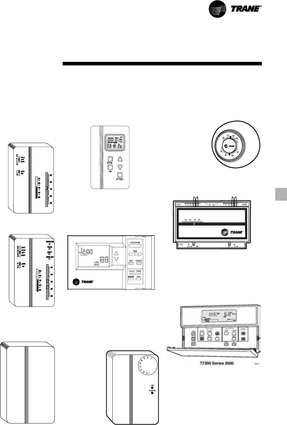
33
RT-PRC016-EN
Conventional Thermostats
Conventional Thermostats are the
building occupant’s comfort control
devises when a generic thermostat is
desired.
Manual
Changeover —
One Heat, One
Cool Thermostat.
Heat, Cool or Off
System Switch.
Fan Auto or On
Switch. Set Point
Dial. Adjustable
Heat Anticipator.
Automatic Changeover — One Heat,
Two Cool Thermostat. Off, Auto System
Switch. Auto/On Fan Switch.
Programmable Electronic Night Setback
Thermostat — Heating setback and
cooling setup with 7-day, programming
capability. Available in two-stage
heating/cooling or one-stage heating/
cooling versions with automatic
changeover.
Zone Sensors
Zone Sensors are the building
occupant’s comfort control devices for
Precedent™ units with the ReliaTel
control. The zone sensor offering
operates with the Reliatel
microprocessor
Manual Changeover — Heat, Cool or Off
System Switch. Fan Auto or Off Switch.
One
temperature
setpoint lever.
Manual/Automatic Changeover —Auto,
Heat, Cool or Off System Switch. Fan
Auto or Off
Switch. Two
temperature
setpoint
levers. Optional
Status Indication
LED lights,
System On,
Heat, Cool, or
Service.
Remote Sensor — Sensor(s) available
for all zone sensors to provide
remote sensing
capabilities.
Zone Controls
Non-programmable manual auto
changeover with digital LCD Display —
Auto, heat, cool or off mode selection
button. Auto or off fan bottom. Status
indication LCD indicators — System on,
heat, cool, or service.
Programmable Night Setback — Auto
or manual changeover with seven-day
programming. Keyboard selection of
Heat, Cool, Fan, Auto, or On.
All programmable sensors have
System On, Heat, Cool, Service LED/
indicators as standard. Night Setback
Sensors have one (1) Occupied, one (1)
Unoccuped, and two (2) Override
programs per day.
Integrated Comfort™ System —
Sensor(s) available with optional
temperature
adjustment and
override buttons
to provide
central control
through a Trane
Integrated
Comfort™
system.
34 RT-PRC016-EN
Table ED-3 — Electrical Characteristics - Evaporator Fan Motor - 50 Hz
Standard Evaporator Fan Motor Oversized Evaporator Fan Motor
Unit Amps Amps
Model No. No. Volts Phase HP FLA LRA No. Volts Phase HP FLA LRA
TSC060AD 1 380-415 3 1.5 4.3 25.3 - - - - - -
TSC072AD 1 380-415 3 1.5 4.3 25.3 1 380-415 3 2.0 5.3 36.4
TSC090AD 1 380-415 3 2.0 5.3 36.4 1 380-415 3 3.0 7.0 57.0
TSC102AD 1 380-415 3 2.0 5.3 36.4 1 380-415 3 3.0 7.0 57.0
TSC120AD 1 380-415 3 3.0 7.0 57.0 - - - - - -
Table ED-4 — Electrical Characteristics - Compressor Motor and Condenser Motor - 50 Hz
Compressor Motor Condenser Fan Motor
Unit Amps Amps
Model No. No. Volts Phase HP1RPM RLA1LRA1No. Phase HP FLA LRA
TSC060AD 1 380-415 3 5.7 2875 9.5 74.00 1 1 0.40 1.9 2.8
TSC072AD 1 380-415 3 7.5 2875 12.7 95.00 1 1 0.75 2.8 7.1
TSC090AD 1 380-415 3 8.3 2875 13.20 100.00 1 1 0.75 2.8 7.1
TSC102AD 2 380-415 3 6.0/3.8 2875 9.3/6.9 74.0/48.0 1 1 0.75 2.8 7.1
TSC120AD 2 380-415 3 6.0/4.8 2875 9.9/8.5 74.0/61.8 1 1 0.75 2.8 7.1
Note:
1. Comp1/Comp2
Electrical
Data
Table ED-1 — Unit Wiring
Standard Indoor Fan Motor Oversized Indoor Fan Motor
Unit Minimum Maximum Fuse Minimum Maximum Fuse
Unit Operating Circuit Size Or Maximum Circuit Size Or Maximum
Model No. Voltage Range Ampacitiy Circuit Breaker1Ampacitiy Circuit Breaker1
TSC060AD 342-456 17.7 25 17.7 25
TSC072AD 342-456 23.2 35 24.2 35
TSC090AD 342-456 24.8 35 26.5 35
TSC102AD 342-456 26.8 35 28.5 35
TSC120AD 342-456 31.2 40 31.2 40
Notes:
1. All units to be installed under local codes
Table ED-2 — Unit Wiring With Electric Heat Single Point Connection — 380-415 Volts
Standard Indoor Fan Motor Oversized Indoor Fan Motor
Minimum Maximum Fuse Minimum Maximum Fuse
Unit Heater Heater2Control Circuit Size Or Maximum Circuit Size Or Maximum
Model No. Model No. kW Rating MBH Stages Ampacitiy Circuit Breaker1Ampacitiy Circuit Breaker1
TSC060AD BAYHTRR412A 7.5 / 9.0 26 / 31 2 19.8 / 21.0 25 / 25 19.8 / 21.0 25 / 25
BAYHTRR418A 10.9 / 13.0 38 / 45 2 26.1 / 28.0 30 / 30 26.1 / 28.0 30 / 30
BAYHTRR423A 14.4 / 17.2 50 / 59 2 32.8 / 35.3 35 / 40 32.8 / 35.3 35 / 40
TSC072AD BAYHTRS418A 11.3 / 13.5 39 / 47 1 26.9 / 28.9 35 / 35 28.1 / 30.1 35 / 35
BAYHTRS427A 16.9 / 20.2 58 / 69 2 37.5 / 40.5 40 / 45 38.8 / 41.8 40 / 45
BAYHTRS436A 22.6 / 26.9 78 / 92 2 48.3 / 52.1 50 / 60 49.5 / 53.4 50 / 60
TSC090AD BAYHTRS418A 11.3 / 13.5 39 / 47 1 28.1 / 30.1 35 / 35 30.3 / 32.3 35 / 35
BAYHTRS427A 16.9 / 20.2 58 / 69 2 38.8 / 41.8 40 / 45 40.9 / 43.9 45 / 45
BAYHTRS436A 22.6 / 26.9 78 / 92 2 49.5 / 53.4 50 / 60 51.6 / 55.5 60 / 60
TSC102AD BAYHTRT427A 16.9 / 20.2 58 / 69 2 38.8 / 41.8 40 / 45 40.9 / 43.9 45 / 45
BAYHTRT436A 22.6 / 26.9 78 / 92 2 49.5 / 53.4 50 / 60 51.6 / 55.5 60 / 60
TSC120AD BAYHTRT427A 16.9 / 20.2 58 / 69 2 40.9 / 43.9 45 / 45 40.9 / 43.9 45 / 45
BAYHTRT436A 22.6 / 26.9 78 / 92 2 51.6 / 55.5 60 / 60 51.6 / 55.5 60 / 60
BAYHTRT454A 33.8 / 40.4 116 / 138 2 73.1 / 79.0 80 / 80 73.1 / 79.0 80 / 80
Notes:
1. All units to be installed under local codes
2. kW and MBH shown for 380V / 415V
35
RT-PRC016-EN
For specific wiring information, see the installation instructions.
All wiring except power wires is low voltage.
All customer supplied wiring to be copper and must conform to NEC or CEC and local electrical codes. Wiring shown dotted is to be furnished and installed by the customer.
DISCONNECT
SWITCH
(BY OTHERS)
ROOFTOP
UNIT
ZONE SENSOR
OR THERMOSTAT
Jobsite
Connections
Zone Sensors — Typical Number Of Wires
A — Manual Changeover . . . . . . . . . . . . . . . . . 4
Manual/Auto Changeover . . . . . . . . . . . . . 5
Manual/Auto Changeover with
Status Indication LED’s . . . . . . . . . . . . . 10
Programmable Night Setback with
Status Indication LED’s . . . . . . . . . . . . . . 7
Thermostats — Typical Number of Wires
A — 3 wires, 24-volts, Cooling Only
4 wires, 24-volts, with Electric Heat
B — 3 Power Wires + 1 Ground Wire (three phase)
2 Power Wires + 1 Ground Wire (single phase)
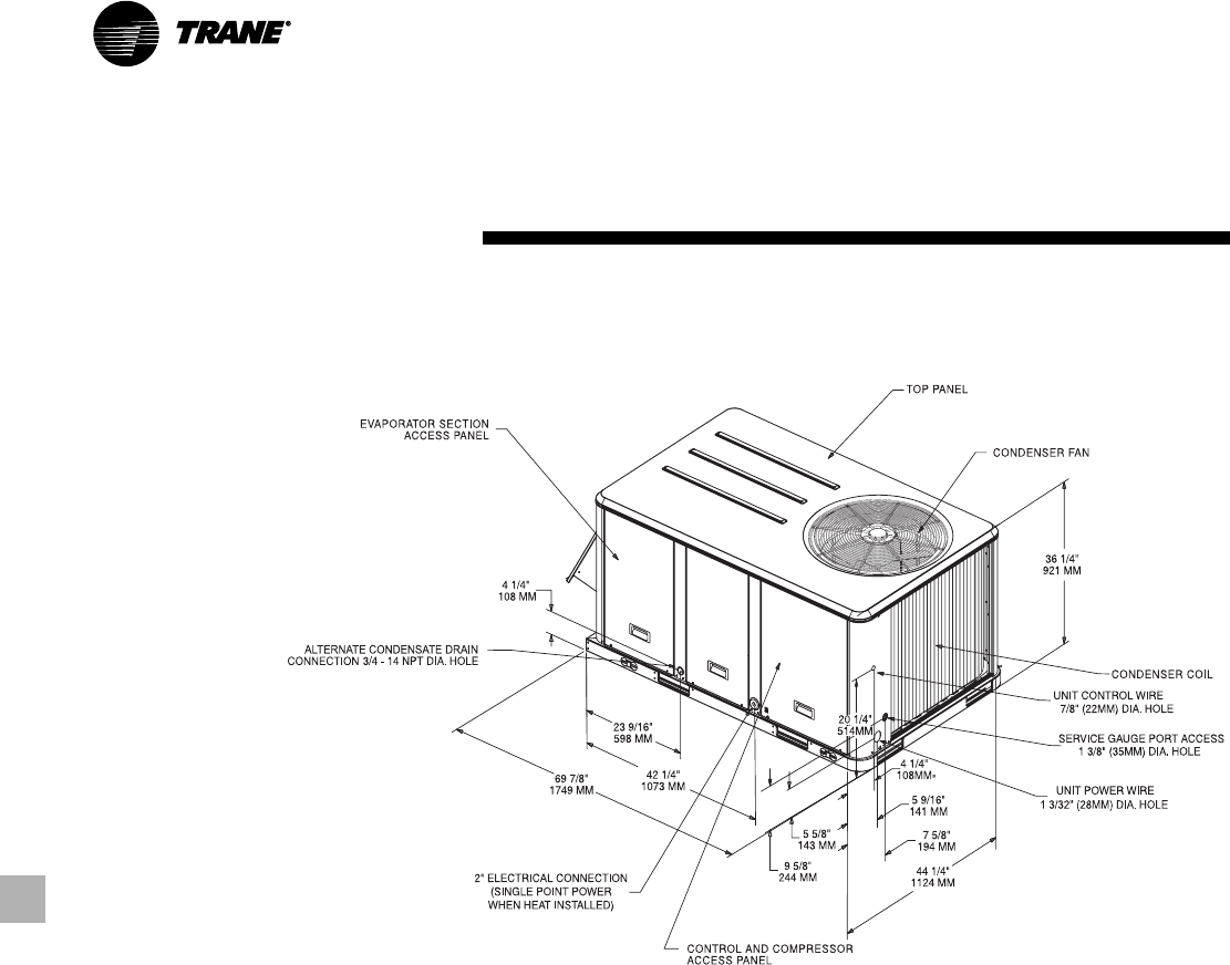
36 RT-PRC016-EN
Dimensional
Data
All dimensions are in inches/millimeters.
TSC060
TSC060
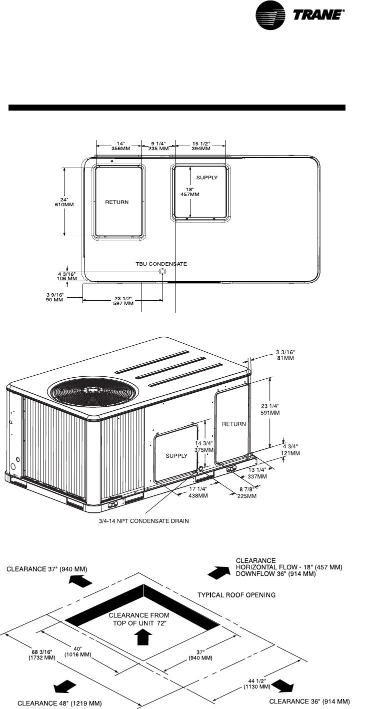
37
RT-PRC016-EN
Dimensional
Data TSC060
All dimensions are in inches/millimeters.
TSC060 — Horizontal Airflow Supply/Return
TSC060 — Downflow Airflow Supply/Return
TSC060 — Unit Clearance and Roof Opening
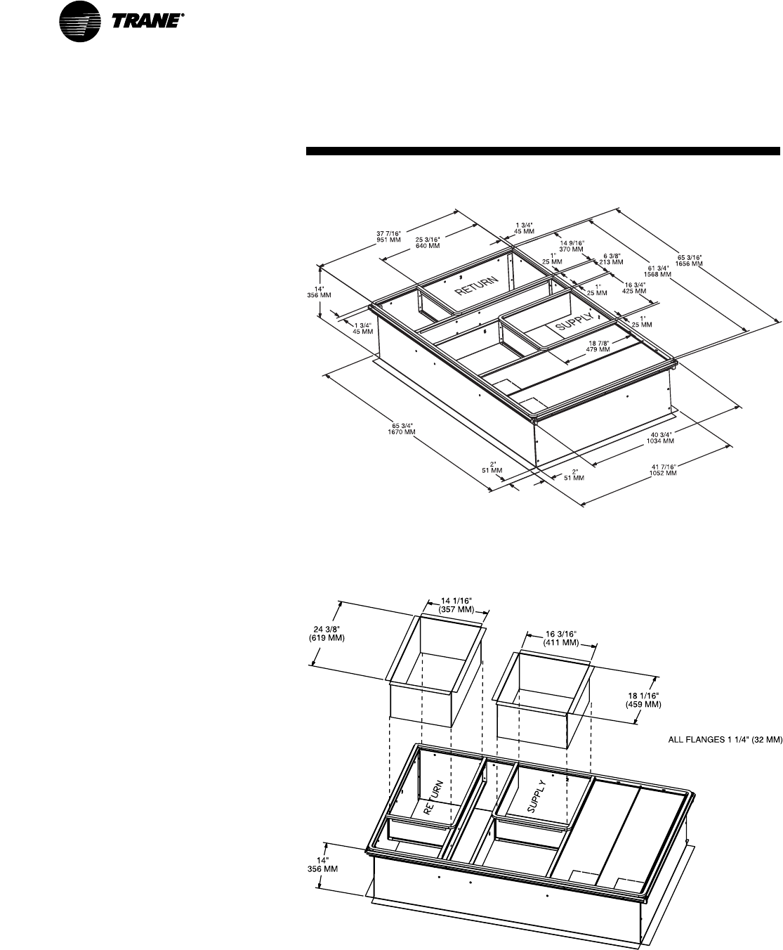
38 RT-PRC016-EN
Dimensional
Data TSC060
All dimensions are in inches/millimeters.
TSC060 — Downflow Duct Connections — Field Fabricated
TSC060 — Roof Curb
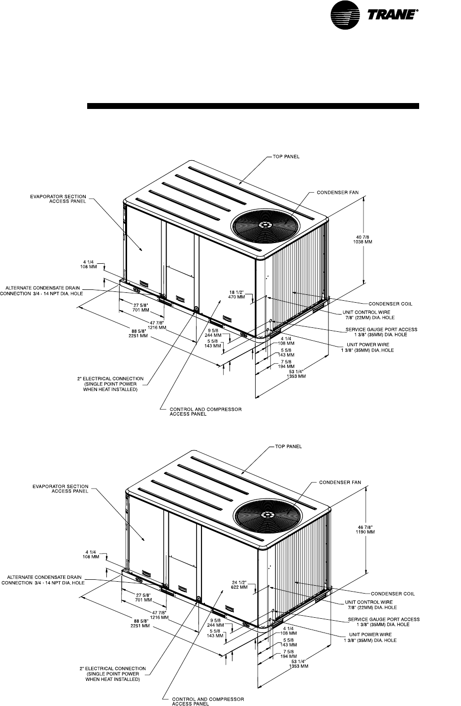
39
RT-PRC016-EN
Dimensional
Data TSC072-120
All dimensions are in inches/millimeters.
TSC072-090
TSC102-120
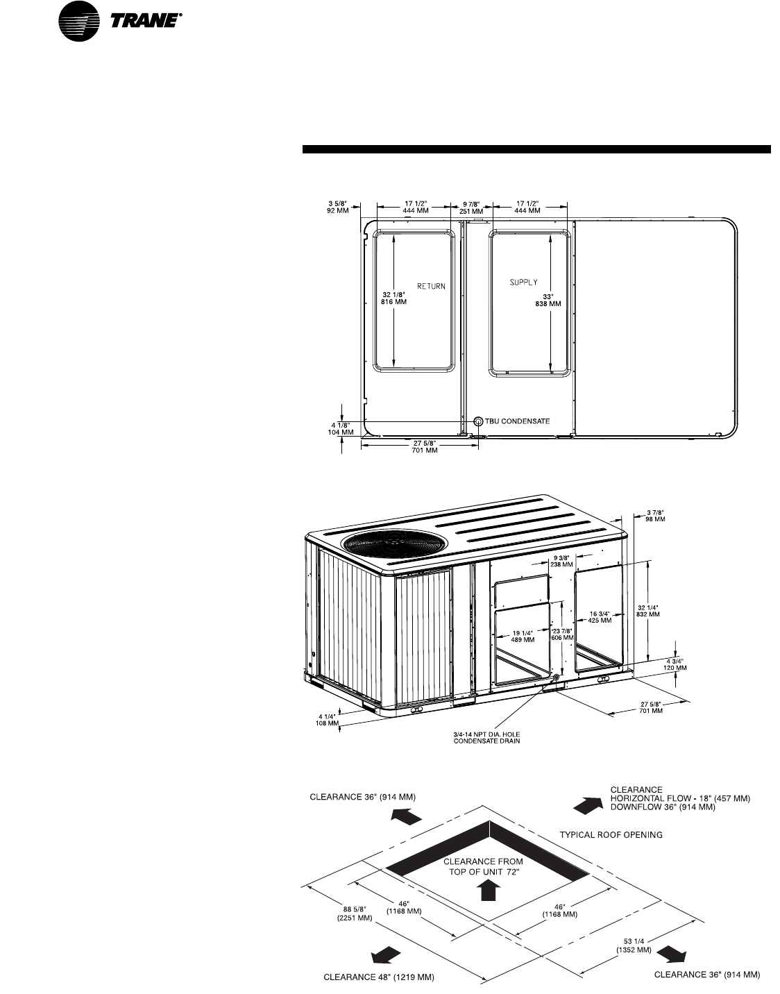
40 RT-PRC016-EN
Dimensional
Data TSC072-120
All dimensions are in inches/millimeters.
TSC072-120 — Downflow Airflow Supply
and Return
TSC072-120 — Horizontal Airflow Supply
and Return
TSC072-120 — Unit Clearance and Roof
Opening
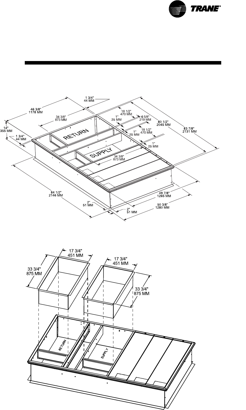
41
RT-PRC016-EN
Dimensional
Data TSC072-120
All dimensions are in inches/millimeters.
ALL FLANGES 1 1/4” (31 MM)
TSC072-120 — Downflow Duct Connections —
Field Fabricated
TSC072-120 — Roof Curb
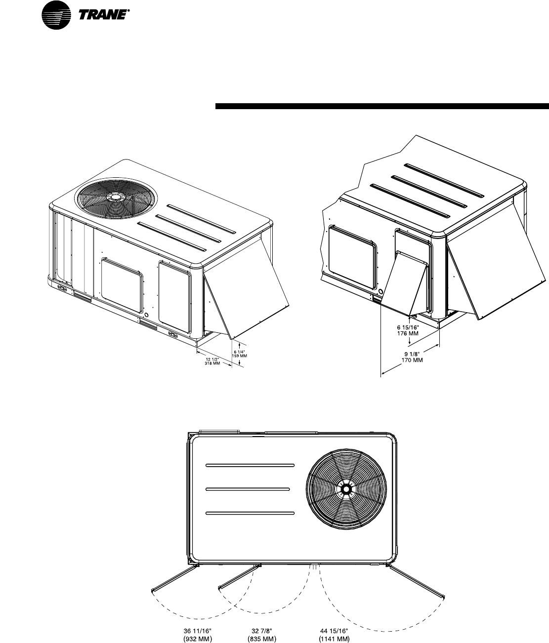
42 RT-PRC016-EN
Dimensional
Data
TSC060
Options/Accessories
All dimensions are in inches/millimeters.
TSC060 — Economizer , Manual or Motorized Fresh Air Damper TSC060 — Barometric Relief Damper Hood
TSC060 — Swing Diameter for Hinged Doors Option
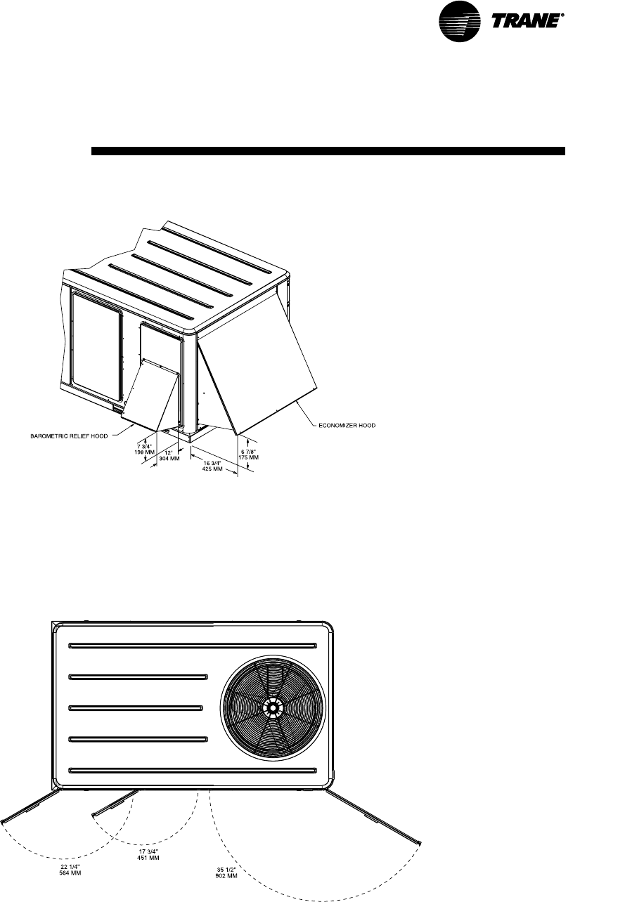
43
RT-PRC016-EN
Dimensional
Data
TSC072-120
Options/Accessories
All dimensions are in inches/millimeters.
TSC072-120 — Economizer and Barometric
Relief Damper Hoods
TSC072-120 — Swing Diameter for
Hinged Door(s) Option
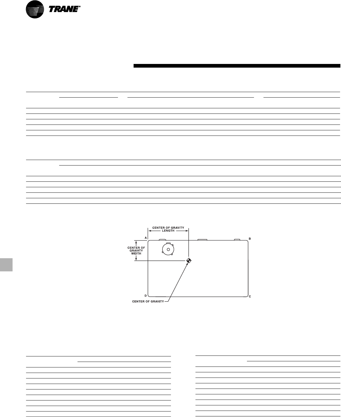
44 RT-PRC016-EN
Weights
Table W-1 - Maximum Unit and Corner Weights and Center of Gravity Dimensions (SI)
Maximum Weights(2) (kg) Corner Weights(1) (kg) Center of Gravity (mm)
Unit
Model No. Shipping(2) Net(2) A B C D Length Width
TSC060AD 270 235 75 56 48 56 790 480
TSC072AD 373 326 107 83 58 78 970 560
TSC090AD 436 389 131 101 67 89 970 530
TSC102AD 453 405 133 106 72 94 990 560
TSC120AD 493 445 147 115 81 104 990 560
Notes:
(1) Corner weights are given for information only. All models must be supported continuously by a curb or equivalent frame support.
(2) Weights are approximate.
Table W-1a - Maximum Unit and Corner Weights and Center of Gravity Dimensions (IP)
Maximum Weights (lbs) Corner Weights(1) (lbs) Center of Gravity (in)
Unit
Model No. Shipping(2) Net A B C D Length Width
TSC060AD 595 518 165 124 105 124 31 19
TSC072AD 823 718 235 182 128 173 38 22
TSC090AD 962 857 289 222 148 197 38 21
TSC102AD 998 893 294 233 159 207 39 22
TSC120AD 1087 982 323 253 178 229 39 22
Notes:
(1) Corner weights are given for information only. All models must be supported continuously by a curb or equivalent frame support.
(2) Weights are approximate.
Table W-2 - Accessory Net Weights
(1) (2)
(kg)
Net Weights(2)
Accessory(3) TSC060 TSC072-120
Economizer 12 16
Barometric Relief 3 5
Motorized Outside Air Damper 9 14
Manual Outside Air Damper 7 12
Roof Curb 32 52
Oversized Motor 2 4
Coil Guards 5 9
Hinged Doors 5 5
Electric Heaters 7 14
Notes:
(1) Weights for options not listed are < 3 kg.
(2) Net weight should be added to unit weight when ordering factory-installed
accessories.
(3) Some accessories not available on all units.
Table W-2a - Accessory Net Weights
(1) (2)
(lbs)
Net Weights(2)
Accessory(3) TSC060 TSC072-120
Economizer 26 36
Barometric Relief 7 10
Motorized Outside Air Damper 20 30
Manual Outside Air Damper 16 26
Roof Curb 70 115
Oversized Motor 5 8
Coil Guards 12 20
Hinged Doors 10 12
Electric Heaters 15 30
Notes:
(1) Weights for options not listed are < 5 lbs.
2) Net weight should be added to unit weight when ordering factory-installed
accessories.
(3) Some accessories not available on all units.

45
RT-PRC016-EN
Mechanical
Specifications
General
The units shall be convertible airflow. The
operating range shall be between 46°C
and -18°C (115°F and 0°F) in cooling as
standard from the factory for all units. All
units shall be factory assembled,
internally wired, fully charged with R-22,
and 100 percent run tested to check
cooling operation, fan and blower
rotation, and control sequence before
leaving the factory. Wiring internal to the
unit shall be colored and numbered for
simplified identification.
Casing
Unit casing shall be constructed of zinc
coated, heavy gauge, galvanized steel.
Exterior surfaces shall be cleaned,
phosphatized, and finished with a
weather-resistant baked enamel finish.
Cabinet construction shall allow for all
maintenance on one side of the unit.
Service panels shall have lifting handles
and be removed and reinstalled by
removing only a single fastener while
providing a water and air tight seal. All
exposed vertical panels and top covers in
the indoor air section shall be insulated
with a cleanable foil-faced, fire-retardent
permanent, odorless glass fiber material.
The base of the unit shall be insulated
with 13 mm, 16 kg (1/2 inch, 1 pound)
density foil-faced, closed-cell material. All
insulation edges shall be either captured
or sealed.The unit’s base pan shall have
no penetrations within the perimeter of
the curb other than the raised 29 mm (11/8
inch high downflow supply/return
openings to provide an added water
integrity precaution, if the condensate
drain backs up. The base of the unit shall
have provisions for forklift and crane
lifting, with forklift capabilities on three
sides of the unit.
Unit Top
The top cover shall be one piece
construction or where seams exist, it
shall be double-hemmed and gasket-
sealed. The ribbed top adds extra
strength and prevents water from
pooling on unit top.
Filters
One inch, throwaway filters shall be
standard on all 5 ton units. The filter rack
can be converted to two inch capability.
50 mm (2 inch) filters shall be factory
supplied on all 6-10 ton units. Optional 50
mm (2 inch) pleated filters shall be
available.
Compressors
All units shall have direct-drive, hermetic,
scroll type compressors with centrifugal
type oil pumps. Motor shall be suction
gas-cooled and shall have a voltage
utilization range of plus or minus 10
percent of unit nameplate voltage.
Internal overloads shall be provided with
the scroll compressors. Low and high
pressure switches shall be standard.
Refrigerant Circuits
Service pressure ports, and refrigerant
line filter driers are factory-installed as
standard. An area shall be provided for
replacement suction line driers.
Evaporator and Condenser Coils
Internally finned, 8 mm (5/16”) copper
tubes mechanically bonded to a
configured aluminum plate fin shall be
standard. Coils shall be leak tested at the
factory to ensure the pressure integrity.
The evaporator coil and condenser coil
shall be leak tested to 1375 kPa (200 psig)
and pressure tested to 3100 kPa (450
psig). The condenser coil shall have a
patent pending 1 + 1 + 1 hybrid coil
designed with slight gaps for ease of
cleaning. A removeable, reversible,
double-sloped condensate drain pan with
provision for through the base
condensate drain is standard.
Outdoor Fans
The outdoor fan shall be direct-drive,
statically and dynamically balanced,
draw-through in the vertical discharge
position. The fan motor shall be
permanently lubricated and shall have
built-in thermal overload protection.
Indoor Fan
All units shall have belt drive motors.
Units with belt drive motors shall have
an adjustable idler-arm assembly for
quick-adjustment to fan belts and motor
sheaves. All motors shall be thermally
protected. Oversized motors shall be
available for high static operations.
Controls
Unit shall be completely factory-wired
with necessary controls and contactor
pressure lugs or terminal block for
power wiring. Units shall have single
point power connection as standard.
Unit shall provide an external location
for mounting a fused disconnect device.
Microprocessor controls provide for all
24 volt control functions. The resident
control algorithms shall make all
heating, cooling, and/or ventilating
decisions in response to electronic
signals from sensors measuring indoor
and outdoor temperatures. The control
algorithm maintains accurate
temperature control, minimizes drift
from set point, and provides better
building comfort. A centralized
Microprocessor shall provide anti-short
cycle timing and time delay between
compressors to provide a higher level of
machine protection.
46 RT-PRC016-EN
Accessories/Options
Electric Heaters
Field-installed electric heat modules shall
be available for installation within basic
unit. Electric heater elements shall be
constructed of heavy-duty nickel
chromium elements internally delta
connected for 200 volt, wye connected
for 380-415 volt. Staging shall be
achieved through the unitary control
processor (UCP). Each heater package
shall have automatically reset high limit
control operating through heating
element contactors. All heaters shall be
individually fused from the factory, where
required. Power assemblies shall provide
single-point connection.
Roof Curb
The roof curb shall be designed to mate
with the unit’s downflow supply and
return and provide support and a water
tight installation when installed properly.
The roof curb design shall allow field-
fabricated rectangular supply/return
ductwork to be connected directly to the
curb. Curb shall be shipped knocked down
for field assembly and shall include wood
nailer strips.
Economizer
This accessory shall be either field or
factory-installed and shall be available
with or without barometric relief. The
assembly includes fully modulating 0-100
percent motor and dampers, minimum
position setting, preset linkage, wiring
harness with plug, spring return actuator
and fixed dry bulb control. The barometric
relief shall provide a pressure operated
damper that shall be gravity closing and
shall prohibit entrance of outside air
during the equipment “off” cycle.
Optional solid state or differential
enthalpy control shall be available for
either factory or field installation. The
factory-installed economizer arrives in
the shipping position and shall be moved
to the operating position by the installing
contractor.
Phase Monitor
Phase monitor shall provide 100%
protection for motors and compressors
against problems caused by phase loss,
phase imbalance, and phase reversal.
Phase monitor is equipped with an LED
that provides an ON or FAULT indicator.
Remote Potentiometer
The minimum position setting of the
economizer shall be adjusted with this
accessory.
Manual Outside Air Damper
Factory or field-installed rain hood and
screen shall provide up to 50 percent
outside air.
Motorized Outside Air Dampers
Factory or field-installed manually set
outdoor air dampers shall provide up to
50 percent outside air. Once set, outdoor
air dampers shall open to set position
when indoor fan starts. The damper shall
close to the full closed position when
indoor fan shuts down.
Mechanical
Specifications
Discharge Air Sensing
This factory of field-installed option
provides true discharge air sensing in
heating models. This sensor is a status
indicator readable through Tracer™ or
Tracker™.
Oversized Motors
Factory or field-installed oversized
motors shall be available for high static
applications.
Clogged Filter/Fan Failure Switch
A dedicated differential pressure switch is
available, factory-installed, to achieve
active fan failure indication and/or
clogged filter indication. These indications
will be registered with either a zone
sensor with status indication lights or an
Integrated Comfort™ System.
High Pressure Cutout
Standard on all units.
Hinged Access Doors
Sheet metal hinges are available factory-
installed on the Filter/Evaporator, Supply
Fan/Heat, and the Compressor/Control
Access Doors.
Black Epoxy Coated Condenser Coil
The coil provides corrosion protection to
condenser coils for seacoast application.
The protection is a factory-applied
thermoset vinyl coating, bonded to
normal aluminum fin stock. The uniform
thickness of the bonded vinyl layer
exhibits excellent corrosion protection.

47
RT-PRC016-EN
Mechanical
Specifications
Control Options
Comm-3/4 Trane Communication
Interface
This factory or field-installed option shall
be provided to interface microprocessor
controlled units with the Trane Integrated
Comfort™ systems.
Comm-5 LonTalk Communication
Interface
This factory or field-installed option shall
be provided to allow the unit to
communicate as a Trane Comm-5 device
or directly with generic LonTalk Network
Building Automation System Controls.
Zone Sensor
This field-installed control shall be
provided to interface with the Micro
equipped units and shall be available in
either manual, automatic programmable
with night setback, with system
malfunction lights, or remote sensor
options.
Thermostats
Two stage heating and cooling operation
or one stage heating and cooling shall be
available, for field installation, in either
manual or automatic changeover.
Automatic programmable electronic with
night set back shall also be available.
Differential Pressure Switches
These factory or field-installed sensors
allow individual fan failure and dirty filter
indication for microprocessor controlled
units. The fan failure switch will disable all
unit functions and “flash” the Service
LED on the zone sensor. The dirty filter
switch will light the Service LED on the
zone sensor and will allow continued unit
operation.
Reference Enthalpy Control
Replaces the dry bulb control with a wet
bulb changeover controller which has a
fully adjustable set point. Enthalpy control
offers a higher level of comfort control,
along with energy savings potential, than
the standard dry bulb control. This is due
to the additional wet bulb sensing
capability. This option shall be available
for microprocessor controlled units. It can
be field-installed, or factory-installed with
the factory-installed economizer.
Differential Enthalpy Control
Replaces the standard dry bulb control
with two enthalpy sensors that compare
total heat content of the indoor air and
outdoor air to determine the most
efficient air source. This control option
offers the highest level of comfort control,
plus energy efficiency, available. This
option shall be available for
microprocessor controlled units. It can be
field-installed, or factory-installed with the
factory-installed economizer.
Low Ambient Cooling
All microprocessor units shall have
cooling capabilities down to 18°C (0°F) as
standard.

Literature Order Number
File Number
Supersedes
Stocking Location
Trane has a policy of continuous product and product data improvement and reserves the right to change
design and specifications without notice
Trane
A business of American Standard Companies
www.trane.com
For more information, contact your local district
office or e-mail us at comfort@trane.com
RT-PRC016-EN
PL-UN-000-RT-PRC016-EN-02-04
PL-UN-000-RT-PRC016-EN-12-03
03-03 Webb/Mason 02-04 Electronic Only
