Trane Varitrac Dampers Installation And Maintenance Manual
Trane Air Conditioner Unit Control Module (UCM) 4.2 Retrofit VAV vav-svn03a-en
2015-04-02
: Trane Trane-Varitrac-Dampers-Installation-And-Maintenance-Manual-684391 trane-varitrac-dampers-installation-and-maintenance-manual-684391 trane pdf
Open the PDF directly: View PDF ![]() .
.
Page Count: 71
Installation Manual
VariTrac™
Central Control Panel
June 2002 VAV-SVN03A-EN

VAV-SVN03A-EN
VariTrac Central Control Panel Installation Manual
This manual and the information in it are the property of American Standard
Inc. and shall not be used or reproduced in whole or in part, except as
intended, without the written permission of American Standard Inc. Since
Trane has a policy of continuous product improvement, it reserves the right
to change design and specification without notice.
Use of the software contained in this package is provided under a software
license agreement. Unauthorized use of the software or related materials
discussed in this manual can result in civil damages and criminal penalties.
The terms of this license are included with the compact disk. Please read
them thoroughly.
Trane has tested the system described in this manual. However, Trane does
not guarantee that the system contains no errors.
Trane reserves the right to revise this publication at any time and to make
changes to its content without obligation to notify any person of such
revision or change.
Trane may have patents or pending patent applications covering items in
this publication. By providing this document, Trane does not imply giving
license to these patents.
The following are trademarks or registered trademarks of Trane: Reliatel,
Tracker, Trane, VariTrac, VariTrane, and Voyager.
Printed in the U.S.A.
© 2002 American Standard Inc. All rights reserved.

VAV-SVN03A-EN i
Contents
About This Manual ............................................ 1
Contents .............................................................................................................. 1
Compliance Information .............................................................................. 1
Specifications ............................................................................................... 1
VariTrac Changeover Bypass System ......................................................... 1
Overview ................................................................................................ 1
Getting Started ...................................................................................... 1
Installing and Configuring the System ................................................ 1
Troubleshooting .................................................................................... 1
Delivered VAV System ................................................................................. 1
Overview ................................................................................................ 1
Getting Started ...................................................................................... 1
Installing and Configuring the System ................................................ 1
Naming Conventions ......................................................................................... 2
Cautionary Statements ...................................................................................... 2
Related Literature ............................................................................................... 2
FCC Information ............................................... 3
VariTrac and Delivered VAV Radio and Television Interference........................ 3
VariTrac Changeover-Bypass System ................ 5
Overview ............................................................................................................. 5
Central Control Panel ................................................................................... 5
Unit Control Module (UCM) ........................................................................ 5
VariTrac Damper ........................................................................................... 5
Communicating Sensor/Bypass Damper Control ...................................... 6
VariTrac Bypass Damper ....................................................................... 6
Communicating Sensor/Bypass Control .............................................. 6
Auxiliary Temperature Sensor ..................................................................... 6
Zone Temperature Sensors .......................................................................... 6
CO2 Sensor ................................................................................................... 7
Occupancy Sensor ....................................................................................... 7
Operator Display (optional) ......................................................................... 7
Service Model Number Description ........................................................... 7
Specifications................................................... 9
VariTrac Central Control Panel ........................................................................... 9
Operator Display .............................................................................................. 10

VAV-SVN03A-ENii
UCM Damper .................................................................................................... 10
Communicating Sensor/Bypass Control Assembly ........................................ 11
Relay Board Binary Outputs .............................................................................11
Wire Specifications ........................................................................................... 11
Getting Started ............................................... 13
Unpack and Inspect the Components ............................................................. 13
Mount the Wiring Base..................................................................................... 14
Mounting Requirements............................................................................ 14
Location ................................................................................................ 14
Operating Environment....................................................................... 14
Clearances ............................................................................................ 14
Secure Termination Module Wall ............................................................... 15
Secure Termination Module to Conduit Box............................................. 16
Install VariTrac CCP Relay Board ............................................................... 16
Wire AC Power .................................................................................................. 17
CCP Field Wiring ......................................................................................... 17
AC Power Wiring .................................................................................. 18
AC Power Checkout ............................................................................. 18
Binary Input Wiring .......................................................................................... 18
Priority Shutdown Input Wiring .......................................................... 18
Occupied/Unoccupied Input Wiring ................................................... 19
Output Wiring ................................................................................................... 19
Install the Bypass Dampers and Communicating
Sensor/Bypass Control Assembly ................................................................... 20
Install Bypass Dampers ............................................................................. 20
Bypass Damper Wiring .............................................................................. 21
Mount the Communicating Sensor/Bypass Control ................................ 21
Connect the Communicating Sensor/Bypass Control Wiring ................. 22
Install the VariTrac Dampers ............................................................................ 23
Connect UCM Wiring ................................................................................. 24
Set the UCM DIP Switches ........................................................................ 25
Slaved Dampers ............................................................................................... 26
Install the Zone Temperature Sensors ............................................................. 28
Location ...................................................................................................... 28
Mounting Standard and Digital Zone Temperature Sensors ................... 29
Wall Mount ........................................................................................... 29
Junction Box Mount ............................................................................ 29
Zone Temperature Sensor Wiring .............................................................. 30
Communication Link Wiring ............................................................................ 32
Mount Main Module .................................................................................. 36
Install Operator Display (optional) ............................................................ 37
Connecting Modem Devices ..................................................................... 38

VAV-SVN03A-EN iii
Connecting PC with VariTrac Software to CCP ......................................... 39
Installation Checklist...................................... 41
Shipment .................................................................................................... 41
Unit Location .............................................................................................. 41
AC Power Wiring ........................................................................................ 41
Communicating Sensor/Bypass Assembly .............................................. 41
Input Wiring ................................................................................................ 41
Output Wiring ............................................................................................. 41
VariTrac Dampers ....................................................................................... 42
Zone Temperature Sensors ........................................................................ 42
UCM Wiring ................................................................................................ 42
Communication Link Wiring ...................................................................... 42
System Start-Up and Checkout ...................... 43
Pre-power-Up Checkout ................................................................................... 43
Central Control Panel ................................................................................. 43
UCM ............................................................................................................ 43
Occupied Mode ................................................................................... 44
Unoccupied Mode ............................................................................... 44
Powering Down the System ...................................................................... 44
UCM LEDs .................................................................................................. 44
Green LED ............................................................................................ 45
Yellow LED ........................................................................................... 45
Tests and Troubleshooting .............................. 47
Displayed Failures ............................................................................................ 47
Static Sensor Calibration Failure ............................................................... 47
Discharge Air Temperature Sensor Failure ............................................... 47
Communication Failure ............................................................................. 47
Zone Sensor Failure ................................................................................... 48
Zone Setpoint Failure ................................................................................ 48
Auxiliary Sensor Failure ............................................................................ 48
Static Pressure Sensor Troubleshooting ................................................... 48
Zone, Auxiliary and System Temperature Sensor Checkout ................... 48
UCM Local Heat Checkout ......................................................................... 50
Central Control Panel Input/Output Test .......................................................... 50
Binary Input Tests ....................................................................................... 50
Communicating Sensor/Bypass Control Test ........................................... 50
Supply Air Temperature Input Test ...................................................... 50
Static Pressure Sensor Input Test ....................................................... 51
Binary Output Test ............................................................................... 51
System Troubleshooting .................................................................................. 51

VAV-SVN03A-ENiv
Delivered VAV System .................................... 53
Overview ........................................................................................................... 53
What is Delivered VAV? ............................................................................. 53
What Delivered VAV is Not ........................................................................ 53
Central Control Panel ................................................................................. 55
Unit Control Module (UCM) ...................................................................... 55
VariTrane VAV Terminal Units .................................................................... 55
VariTrane VAV Terminal Unit Types ............................................................ 55
Single Duct ........................................................................................... 55
Parallel Fan-Powered ........................................................................... 55
Series Fan-Powered ............................................................................. 55
Auxiliary Temperature Sensor ............................................................. 56
Zone Temperature Sensors ................................................................. 56
CO2 Sensor ........................................................................................... 56
Occupancy Sensor ............................................................................... 56
Operator Display.................................................................................. 56
Getting Started ............................................... 57
Installing the Central Control Panel................................................................. 57
Install VariTrane VAV Terminal Units ................................................................ 57
Connect UCM Wiring ................................................................................. 57
Set UCM DIP Switches ............................................................................... 57
Installing Zone Temperature Sensors ....................................................... 57
Communications Link Wiring .................................................................... 57
Installation Checklist...................................... 63
Shipment .................................................................................................... 63
Unit Location .............................................................................................. 63
AC Power Wiring ........................................................................................ 63
Input Wiring ................................................................................................ 63
VariTrane Terminal Units ............................................................................ 63
Zone Temperature Sensors ........................................................................ 63
UCM Wiring ................................................................................................ 63
Communication Link Wiring ...................................................................... 64
Completing Central Control Panel Assembly ................................................. 64
Mount Main Module .................................................................................. 64
Install Operator Display ............................................................................. 64
Connecting Modem Devices ..................................................................... 64

VAV-SVN03A-EN 1
About This Manual
Contents
This manual describes the steps required to install and configure VariTrac™
Changeover Bypass Zoning and Delivered VAV Systems. Sections in this
manual are highlighted below:
Compliance Information
Information about FCC approval and possible radio and telephone interfer-
ence, and the CE compliance statement.
Specifications
Technical specifications for VariTrac Central Control Panel unit and system
components.
VariTrac Changeover Bypass System
Overview
A brief description of a typical VariTrac changeover bypass system.
Getting Started
Pre-installation and setup information.
Installing and Configuring the System
Installation and configuration information, including an installation check-
list.
Troubleshooting
General troubleshooting guidelines for common problems.
Delivered VAV System
Overview
A brief description of a typical delivered VAV system.
Getting Started
Pre-installation and setup information.
Installing and Configuring the System
Installation and configuration information, including an installation check-
list.

VAV-SVN03A-EN2
Naming Conventions
The following is a list of naming conventions used in this manual:
•CCP: Refers to the system Central Control Panel
•VariTrac: Refers to the CCP used in a pressure dependent bypass zoning
system
•Delivered VAV: Refers to the CCP used with a Commercial Voyager VAV
rooftop unit and VariTrane pressure independent VAV boxes
•VAV: Variable air volume
Cautionary Statements
The following cautionary statements signal procedures or conditions that
require particular attention.
WARNING
Indicates a potentially hazardous situation, which, if not avoided, could
result in serious injury or death.
CAUTION
Indicates a potentially hazardous situation, which, if not avoided, may
result in minor or moderate injury.
CAUTION
Indicates a situation in which property-damage-only accidents could occur.
It is also used to alert against unsafe practices.
IMPORTANT
Alerts installer, servicer, or operator to potential actions that could cause
the product or system to operate improperly, but will not likely result in
potential for damage.
Related Literature
VAV-SVX01B-EN: UCM 4.0 and Wireless VAV Communication
VAV-SLB006-EN: Zone Occupancy Sensor
VAV-SLB007-EN: Digital Display Zone Sensor
VAV-SLB008-EN: Zone and Duct CO2 Sensor
VAV-SVP01A-EN: VariTrac Operator’s Guide
About This Manual

VAV-SVN03A-EN 3
FCC Information
VariTrac and Delivered VAV Radio and
Television Interference
VariTrac and Delivered VAV generate, use, and can radiate radio frequency
energy. If not installed and used in accordance with the instruction manual,
interference to radio and television reception may occur. VariTrac and
Delivered VAV are tested and comply with the limits for Class A computing
devices in accordance with the specifications in Subpart J of Part 15 of FCC
rules, to provide reasonable protection against such interference in a
commercial installation.
There is no guarantee that interference will not occur in a particular
installation. If interference does occur, consult a radio or television
technician for suggestions to correct the problem. Also, the booklet
How to
Identify and Resolve Radio-TV Interference Problems
is available from the
U.S. Government Printing Office, Washington, DC 20402.
Order stock #004-000-00345-4.
VAV-SVN03A-EN4
'HFODUDWLRQRI&RQIRUPLW\
Manufacturer’s Name:
Manufacturer’s Address:
Trane
4833 White Bear Parkway
Saint Paul, Minnesota 55110
USA
The manufacturer hereby declares that the product:
Product Name:
Product Number:
Product Option:
VariTrac CCP Controller
X13650940010; X13650942010
Operator Display
Conforms to the following standards or other normative documents:
Electromagnetic Emission:
(by Council Directive 89/336/EEC)
Electromagnetic Immunity:
EN 50081-1:1998
Radiated EN55022: 1998 Class B limit
Conducted EN55022: 1998 Class B limit
EN61326-1:1997 +A1: 1998
EN61000-4-2 ±4 kV contact discharge
±8 kV air discharge
EN61000-4-3 3 V/m
EN61000-4-4 ±1 kV
EN61000-4-5 ±1 kV
EN61000-4-6 3 V
EN61000-4-8 30 A/m
EN61000-4-11 1 cycle/100%
When and where issued
Electromagnetic Emission : 4/3/2001 Bounheng Saycocie
Electromagnetic Immunity: 4/17/2001 Design/Compliance Engineer
Saint Paul, Minnesota USA
Mark of Compliance European Contact
Societe Trane (Epinal, France)
1, rue des Ameriques, B.P. 6
F-88191 Golbey Cedex, France
Phone: (33) 329.31.73.00
Fax: (33) 329.81.24.98
This document validates CE conformity of the VariTrac CCP controller.
FCC Information

VAV-SVN03A-EN 5
VariTrac Changeover-Bypass
System
Overview
VariTrac Changeover-bypass VAV is a comfort system solution designed for
light commercial applications. As the name implies, these systems deliver a
varying volume of air to multiple zones, each with its own thermostat, while
still utilizing a unitary machine with a constant volume fan. Changeover-
bypass VAV combines the comfort benefits of VAV with the cost effective-
ness and simplicity of packaged unitary equipment.
Central Control Panel
The VariTrac Central Control Panel is the central source of communications
and decision making between the individual zones and the air conditioning
unit. Connections to the central control panel are:
•24 Vac power
•binary inputs for an occupied/unoccupied signal and external priority
shutdown signal (optional)
•ICS communication bus to the Trane building automation system (op-
tional)
•UCM communication bus to the zone dampers and communicating
sensor/bypass damper control and Trane Voyager™/Reliatel™ rooftop unit
•binary outputs to heating, cooling, and fan of non-Voyager or Reliatel
rooftop units
Unit Control Module (UCM)
A unit control module is mounted to each individual zone damper. Inputs
and outputs consist of the twisted shielded pair communication link, zone
temperature sensor, optional CO2 and occupancy sensors, 24 Vac power,
damper motor control, and local heat outputs. Local heat may be duct or
space mounted, and can be staged electric, pulse-width modulating electric,
and modulating or staged two-position hot water.
VariTrac Damper
Each VariTrac damper consists of an integrated 24 Vac actuator and control
box that encloses the UCM circuit board. The damper is designed to operate
in static pressures up to 1.75 inches wg.
VariTrac dampers are referred to by their dimensions:
•round damper sizes are 6, 8, 10, 12, 14, and 16 inches. The dampers con-
sists of an 18 gage galvanized steel frame with a round damper blade
assembly.

VAV-SVN03A-EN6
•rectangular damper sizes are 8 x 12, 8 x 14, 8 x 16, 10 x 16, 10 x 20, and
14 x 16 inches. The damper consists of a 16 gage galvanized steel frame
and opposed blade damper assembly.
Communicating Sensor/Bypass Damper Control
The communicating sensor/bypass damper assembly is a bypass damper
and communicating sensor/bypass control that resides on the same bus as
the VariTrac dampers and Voyager/Reliatel rooftop unit.
VariTrac Bypass Damper
Bypass dampers are non-communicating VariTrac dampers which include an
integrated actuator with a pre-wired interconnect cable that plugs into the
communicating sensor/bypass control.
•round bypass damper sizes are 6, 8, 10, and 12 inches. The damper con-
sists of an 18 gage galvanized steel frame with a round damper blade
assembly. The round bypass damper operates in duct static pressures up
to 1.75 inches wg.
•rectangular bypass damper sizes are 14 x 12, 16 x 16, 20 x 20, and 30 x 20
inches. The damper consists of a 13 gage galvanized steel frame and
opposed blade damper assembly. The rectangular bypass damper oper-
ates in duct static pressures up to 2.00 inches wg.
Communicating Sensor/Bypass Control
The Communicating Sensor/Bypass Control is composed of an integrated
UCM board, static pressure, and discharge air temperature sensors. It
directly controls the bypass damper and communicates duct conditions to
the central control panel.
The static pressure sensor measures duct static pressure and positions the
bypass damper(s) to maintain the static pressure setpoint.
The discharge air temperature sensor allows the CCP to determine the heat/
cool action of each individual UCM and cycles the heating and cooling
stages to maintain the discharge air temperature. Discharge air temperature
setpoints are also edited through the operator display or PC software.
Auxiliary Temperature Sensor
The auxiliary temperature sensor allows the operator to monitor air
temperature leaving a reheat device or measure duct temperature for
automatic operation of a standalone UCM.
Zone Temperature Sensors
Five zone temperature sensor configurations are available:
•sensor only
•sensor with adjustable setpoint and communications jack
•sensor with night setback override button, cancel button, and communica-
tions jack
•sensor with adjustable setpoint, night setback override button, cancel
button, and communications jack
VariTrac Changeover-Bypass System
VAV-SVN03A-EN 7
•sensor with digital display, adjustable setpoint, night setpoint override
button, cancel button, and communications jack
CO2 Sensor
A CO2 sensor may be connected to the UCM damper control to sense CO2
levels in the space. This signal is communicated to the CCP for demand
ventilation calculation and control.
Occupancy Sensor
A normally open occupancy sensor contact may be connected to the UCM
damper control binary input to indicate zone occupancy.
Operator Display (optional)
A 1/4 VGA monochrome LCD touch screen display is available for the CCP.
This display provides setup, diagnostic, and seven-day scheduling functions
to the system.
Service Model Number Description
Service model numbers determine product characteristics and are used
when ordering replacement parts. Each digit signifies product characteris-
tics. See Figure 1.
Figure 1: Service Model Number Description
VA DA06 BYP 1
Product Type
Damper Size
VA = VariTrac Product Families
D = Damper
R = Rectangular Damper
A = Development Sequence
DA06 = 6” Damper
DA08 = 8” Damper
DA10 = 10” Damper
DA12 = 12” Damper
DA14 = 14” Damper
DA16 = 16” Damper
RA0812 = 8” x 12” Zone Damper
RA0814 = 8” x 14” Zone Damper
RA0816 = 8” x 16” Zone Damper
RA1016 = 10” x 16” Zone Damper
RA1020 = 10” x 20” Zone Damper
RA1418 = 14” x 18” Zone Damper
RA1412 = 14” x 12” Bypass Damper
RA1616 = 16” x 16” Bypass Damper
RA2020 = 20” x 20” Bypass Damper
RA3020 = 30” x 20” Bypass Damper
Inventory Number
Damper Control
BYPS = Bypass Control
BYR = Rectangular Bypass Control
CHGR = Changeover Control
ELEC = 3 Stage, Primary Heat Disabled Control
NCHW = 1 Stage, Primary Heat Enabled
CO
2
Sensor
VAV-SVN03A-EN8
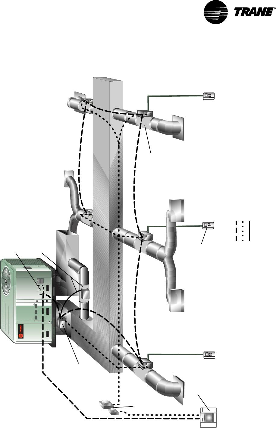
Figure 2: VariTrac Changeover Bypass System Configuration
Legend
Communications Link (2 cond, Level 4 comm wire)
24 Vac
Sensor wiring
Voyager or
Reliatel TCI-3
Bypass Damper
(w/connecting cable assembly)
Zone
Sensor
VariTrac Central
Control Panel
Communicating
Sensor/Bypass
Control Assembly
VariTrac
Zone Damper
24 Vac
Transformer
VariTrac Changeover-Bypass System
VAV-SVN03A-EN 9
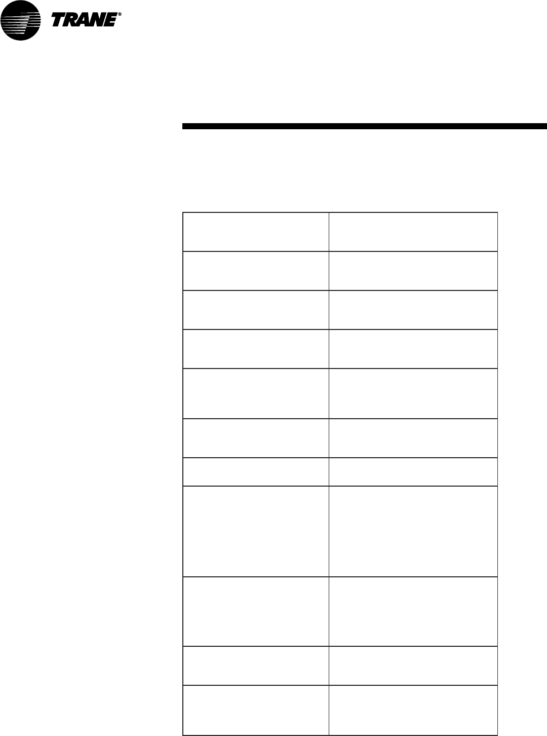
Specifications
VariTrac Central Control Panel
stnemeriuqeRrewoP
AV03,esahpelgnis,zH06,caV03-02
remrofsnart2ssalCmuminim
deriuqer
tnemnorivnEgnitarepO evitaler%09ot01,F°221otF°23
gnisnednoc-non,ytidimuh
tnemnorivnEegarotS evitaler%59ot5,F°581otF°04-
gnisnednoc-non,ytidimuh
tenibaC munelp,erusolcneniser1AMEN
detar
gnitnuoM
roecafrusllawnoyltceridtnuoM
.ni4x.ni4dessecernotnuom
.xobtiudnoc
snoisnemiD 57.2xediw.ni52.01xhgih.ni57.8
.peed.ni
thgieW sdnuop5.1
gniriWkniLnoitacinummoC
ebtsumgniriwknilnoitacinummoC
riapdedleihsdetsiwtGWA224leveL
reppocdennitdednartshtiweriw
eriwlatotmumixaM.srotcudnoc
teemtsumeriW.teef0053sihtgnel
eeS.snoitacificepsenarT
eriWkniLnoitacinummoC“
”.snoitacificepS
tupnIyraniB
:)PCCcarTiraVybdedivorp(egatloV
cdV41ot01
:)PCCcarTiraVybdedivorp(tnerruC
Am41ot01
ebyamstcatnoc”yrd“ylnO:etoN
.stupniyranibotdehcatta
lavorppALU silenaPlortnoClartneCcarTiraVehT
.devorppaLU
pukcaByromeM
-rotarepolla,ssolrewopanopU
carTiraVehtniderotsataddetide
deniatniamsilenaPlortnoClartneC
.yltnenamrep

VAV-SVN03A-EN10
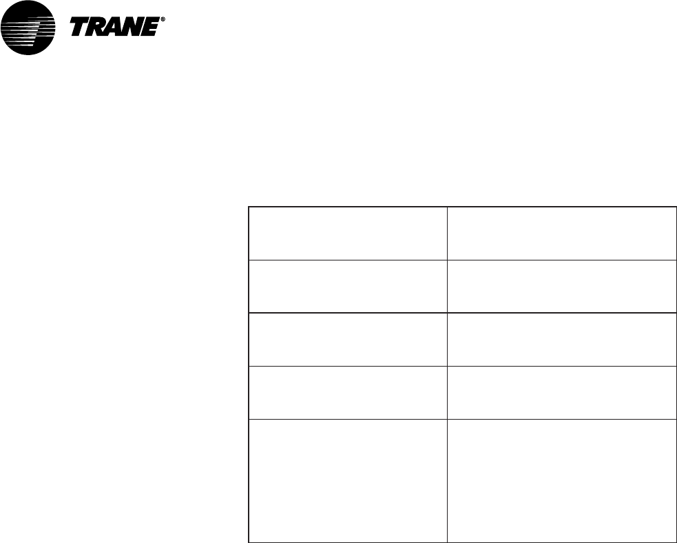
Operator Display
stnemeriuqeRrewoP ybderewopsiyalpsidrotarepoehT
.PCCeht
tnemnorivnEgnitarepO
F°221otF°23
-non,ytidimuhevitaler%09ot01
gnisnednoc
tnemnorivnEegarotS
F°581otF°04-
-non,ytidimuhevitaler%59ot5
gnisnednoc
tenibaC munelp,erusolcneniser1AMEN
detar
gnitnuoM PCCcarTiraVotnoyltceridsgulP
snoisnemiD .ni5.1xediw.ni52.01xhgih.ni57.8
.peed
thgieW sdnuop3
UCM Damper
stnemeriuqeRrewoP
01,esahpelgnis,zH06,caV03ot02
lanoitpofodaolsulp(muminiMAV
remrofsnart2ssalC)stuptuotaeh
deriuqer
tnemnorivnEgnitarepO
F°021otF°23
-non,ytidimuhevitaler%09ot01
gnisnednoc
tnemnorivnEegarotS
F°002otF°05-
-non,ytidimuhevitaler%59ot5
gnisnednoc
xoBlortnoC ,erusolcnelatem1AMEN
detarmunelp
gniriWkniLnoitacinummoC
ebtsumgniriwknilnoitacinummoC
riapdedleihsdetsiwtGWA224leveL
reppocdennitdednartshtiweriw
eriwlatotmumixaM.srotcudnoc
teemtsumeriW.teef0053sihtgnel
:1elbaTeeS.snoitacificepsenarT
eriWkniLnoitacinummoC“
”.snoitacificepS
Specifications
VAV-SVN03A-EN 11
Communicating Sensor/Bypass Control
Assembly
stnemeriuqeRrewoP
51,esahpelgnis,zH06,caV03ot02
remrofsnart2ssalCmuminimAV
deriuqer
tnemnorivnEgnitarepO
F°021otF°23
-non,ytidimuhevitaler%09ot01
gnisnednoc
tnemnorivnEegarotS
F°002otF°05-
-non,ytidimuhevitaler%59ot5
gnisnednoc
xoBlortnoC ,erusolcnelatem1AMEN
detarmunelp
gniriWkniLnoitacinummoC
ebtsumgniriwknilnoitacinummoC
riapdedleihsdetsiwtGWA224leveL
reppocdennitdednartshtiweriw
eriwlatotmumixaM.srotcudnoc
teemtsumeriW.teef0053sihtgnel
:1elbaTeeS.snoitacificepsenarT
eriWkniLnoitacinummoC“
”.snoitacificepS
Relay Board Binary Outputs
Voltage provided: 24 Vac from air conditioning unit
Current: 10 VA maximum
Wire Specifications
Shielded Level 4 communication wire is now recommended for all commu-
nication link wiring on the new VariTrac CCP. This is the same wire which is
recommended for the Tracker Version 10 Comm5 communication link.
The term “Level 4” is used to specify a particular performance of communi-
cation wire and is normally associated with LonTalk™. Level 4 wire is differ-
ent from Category IV (four) wire and Category V (five) wire. The specification
information for Level 4 wire can be found in the “LonWorks™ FTT-10A Free
Topology Transceiver User ’s Guide” at www.echelon.com.
Shielded Level 4 communication wire can be purchased from two qualified
suppliers: Windy City Wire and Connect-Air.
Communicating Sensor/Bypass Control Assembly
VAV-SVN03A-EN12
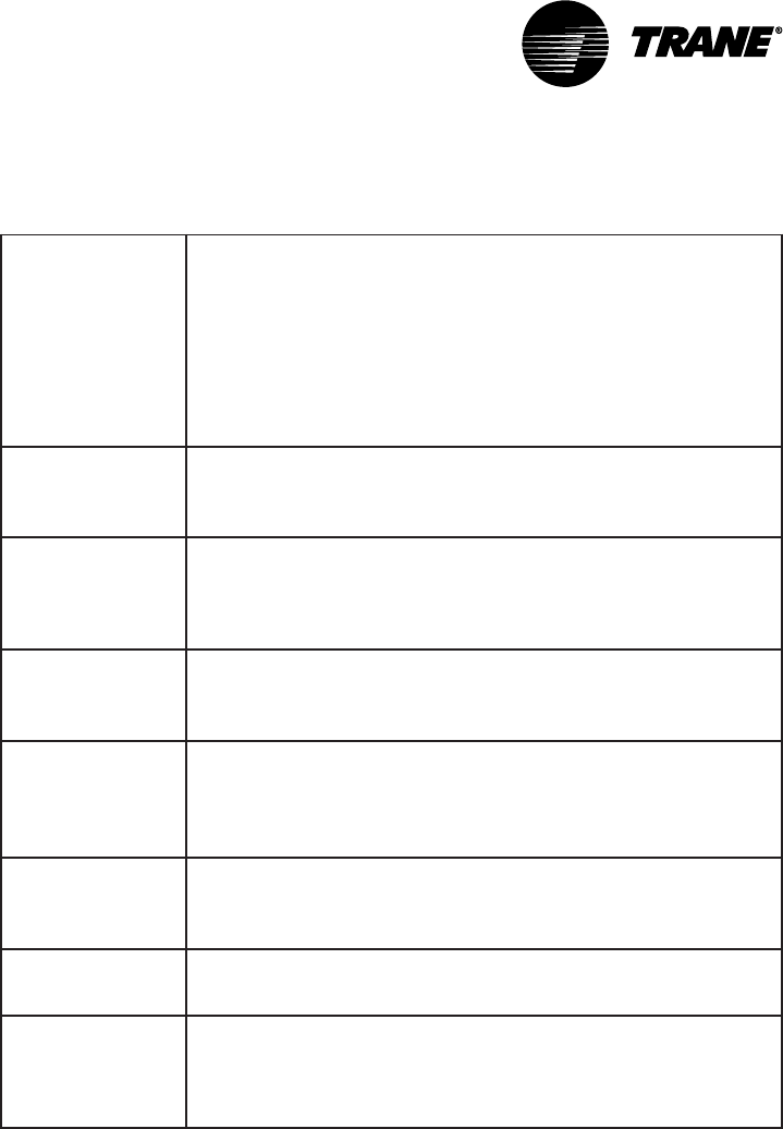
Table 1: Communication Link Wire Specifications
noitacificepS
detaRPMCmunelP4leveL,dedleihS,srotcudnoCGWA22
.rp1:dnoCforebmuN
eulbthgil:roloCtekcaJ
03/7:dnartS.dnoC
"900.0:hcni.kcihttekcaJ.moN
"510.0:nillaw.kcihttekcaJ.moN
"671.0:hcniDOmoN
22:TFMrepthgieW
noitalusnI remylopdedocrolocedargmuimerP
tekcaJ
)munelp(yollaremyloplarutanedargmuimerP•
)munelp-non(CVPRSedargmuimerP•
C°57+otC°0morfesurofelbatiuS•
V003fognitardetsegguS•
dleihS dednartsasulp,liofmunimuladetroppusretseylopllarevO
gnidnuorgetatilicafoteriwniardreppocdennit
gnigakcaP rosloops)m503(.tf0001snotractuo-yap;)m503(.tf0001
sleer
noitacilppA tahtsnoitacilppahtiwelbitapmoceraselbacllA
skroWnoLetaroprocni
®
ygolonhcet
yrtsudnI
slavorppA
selbacCTLPro/dnaP2LC,PMC,MCepyTsaLUybdetsiL
noitallatsni527ro/dna008elcitrACENniesurof
4mmoC:etoN
rofstimilknil
carTiraVwen
PCC
secived53,)niahcysiad(teef0053
Specifications

VAV-SVN03A-EN 13
Getting Started
Familiarize yourself with the system components and preview the
installation procedures before installing and configuring the VariTrac
system.
Installation and configuring procedures appear in suggested order of
performance:
•Unpack and inspect the components
•Mount the wiring base
•Wire AC power
•Binary input wiring
•Output wiring
•Install communicating sensor/bypass damper control
•Install bypass damper(s) and connect to communicating sensor/bypass
control assembly
•Install VariTrac dampers
•Connect UCM wiring
•Set UCM DIP switches
•Install slaved dampers (if used)
•Install zone temperature sensors
•Communication link wiring
•Mount main module
•Install operator display (optional)
•Connecting modem devices
IMPORTANT
The CCP is designed to work with UCM III and IV VariTrac damper and
VariTrane VAV controllers produced beginning January 1995. If any other
dampers are used (especially on a retrofit job), please consult the factory
to confirm VariTrac Central Control Panel compatibility prior to installa-
tion.
Unpack and Inspect the Components
Inspect components for damage. Match each component to the packing list
to ensure that nothing was lost during shipment. Make sure that the litera-
ture is not lost or discarded with the packing material. Visually inspect the
central control panel for damage. All components are thoroughly inspected
before leaving the factory. Any claims for damage incurred in shipping must
be filed with the carrier.
VAV-SVN03A-EN14
Mount the Wiring Base
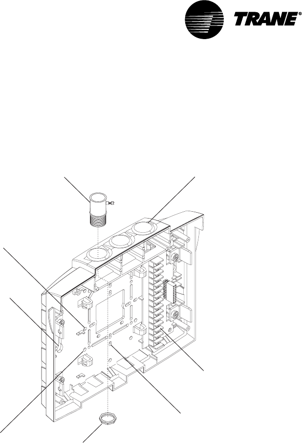
Figure 3: Termination module conduit access and mounting holes
Termination board
Conduit access
(three places)
Two holes for mounting on a wall
(one on each side)
Holes for mounting on a
4 in. x 4 in. conduit box
(four corners)
Holes for mounting on a 2 in. x 4 in.
conduit box vertically
(top and bottom)
Holes for mounting on a 2 in. x 4 in.
conduit box horizontally
(left and right)
Conduit connector
Jamb nut
(attaches to
conduit connector)
Mounting Requirements
Location
The VariTrac Central Control Panel should be mounted at a convenient level
and located where it will be easily accessible. If possible, locate the CCP
near the controlled equipment to reduce wiring cost.
Operating Environment
The VariTrac Central Control Panel is designed for indoor use only. It should
be located in a dust-free and corrosive-free environment, and within a range
of 32° to 120°F, and 10 to 90 percent humidity (non-condensing).
Clearances
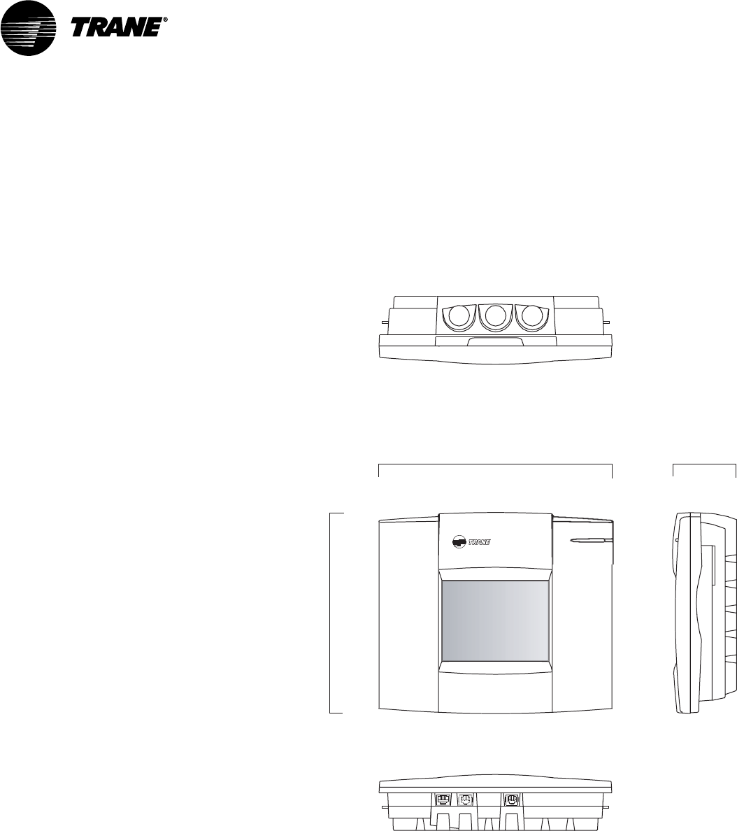
Mount the VariTrac Central Control Panel on any vertical flat surface. The CCP
is approximately 8.75 inches high, 10.25 inches wide and 2.75 inches deep.
Getting Started
VAV-SVN03A-EN 15
The VariTrac Central Control Panel should be easily accessible for making
wiring connections and for servicing. Provide two inches of clearance on the
left and right sides, and sufficient clearance above the unit to make conduit
connections. Sufficient space should be available in front of the unit to
making wiring connections and perform maintenance.
Figure 4: Dimensions for VariTrac Central Control Panel Components
Front view Side view
8.75 in.
(22.38 cm)
2.75 in.
(6.99 cm)
10.25 in.
(26.04 cm)
Top view
Bottom view
Secure Termination Module to Wall
1Mark the location of the two mounting holes on the wall.
2Set the termination module aside and drill mounting holes.
3Secure the termination module to the wall with the supplied hardware
(#10 x 1 in. screw with plastic anchor).
Secure Termination Module to Wall
VAV-SVN03A-EN16
Secure Termination Module to Conduit Box
1Remove the screws from the conduit box.
2Line up the conduit box screw holes on the termination module (Figure 3)
with the screw holes on the conduit box.
3Install the screws.
NOTE: When mounting the termination module to a 4 in. x 4 in. conduit box,
remove the plastic cover over the box for easier access. Do not attempt to break
away excess plastic. Use a hack saw blade and carefully cut away the plastic.
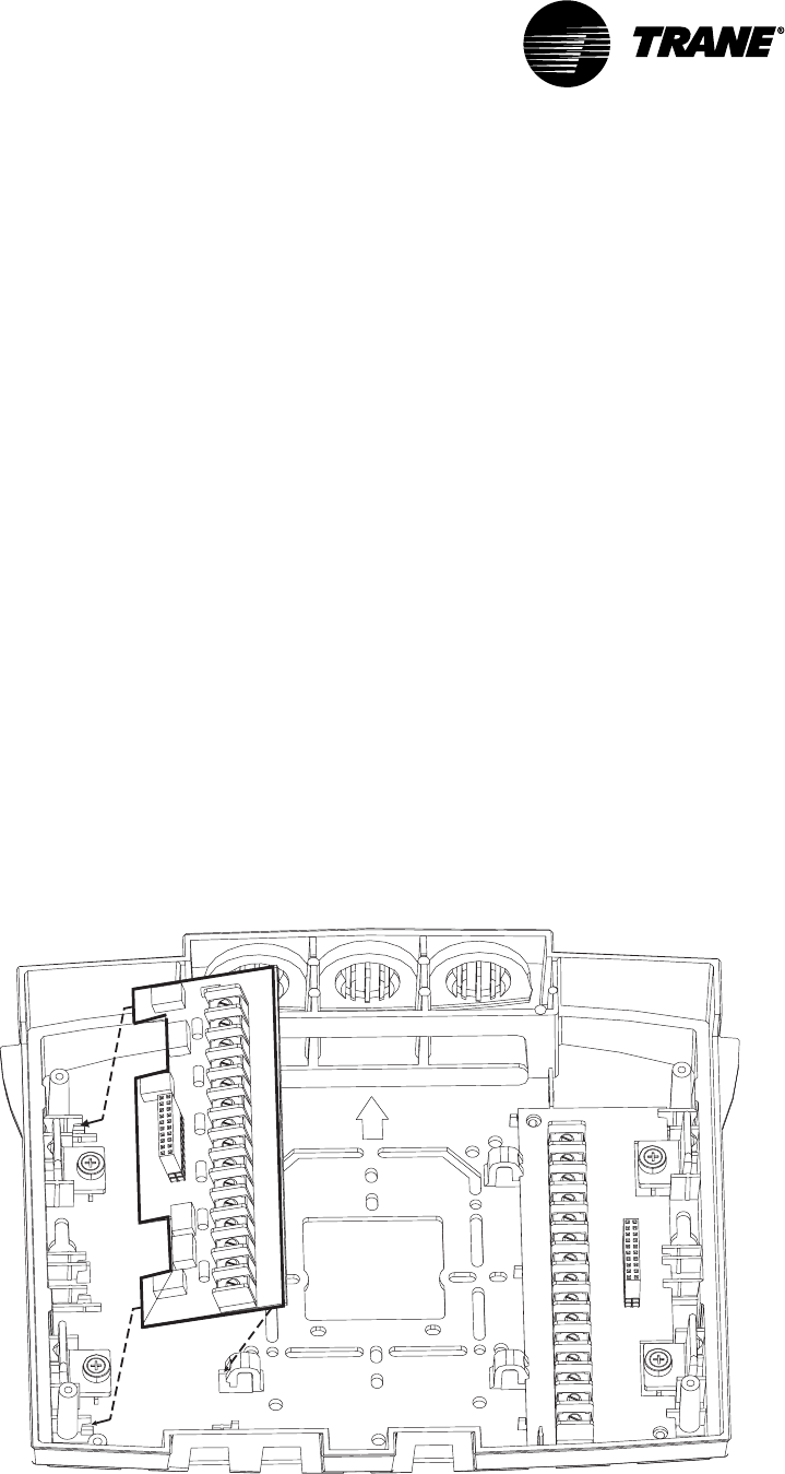
Install VariTrac CCP Relay Board
1Separate the main module and front panel from the termination module.
2Remove the relay board from its packaging.
3Orient the relay board so that its 20-pin socket connector faces left (see
Figure 5).
4Slide the left edge of the board underneath the catches on the left side.
5Rotate the board to the catches on the right side.
6Snap the board into place by pressing on the terminal block or on the
right side of the board.
Figure 5: Installing Optional Relay Board
Getting Started
VAV-SVN03A-EN 17
Wire AC Power
CCP Field Wiring
Field wiring to the VariTrac Central Control Panel includes:
•AC power wiring
•binary input wiring
•communication link wiring
•binary output wiring (requires optional relay board)
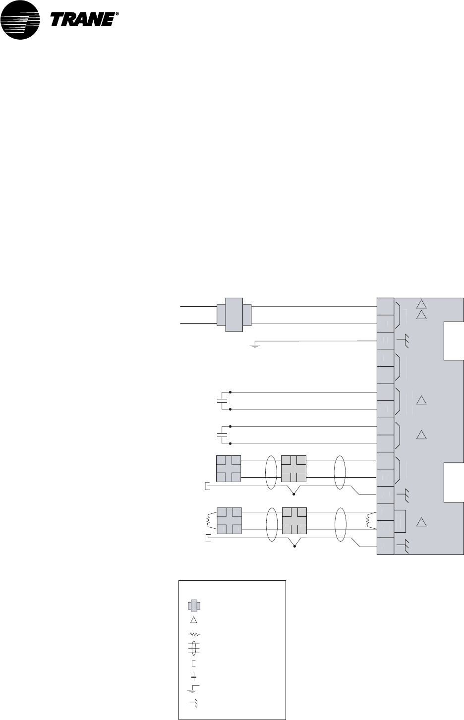
These procedures are detailed in the following sections. Refer to Figure 6 for
wiring connections.
Figure 6: Field Wiring
24V
AC
VA
CO
MM4
CO
M
M
NO
T
US
ED
P
RI
O
RI
TY
S
H
U
TD
O
W
N
OCC
/
UNOC
1
2
3
4
5
6
7
8
9
1
0
11
12
1
3
14
1
5
24
V
a
c
Line volta
ge
Comm5
link
Co
mm
5
lin
k
Comm5 UCMTr
ac
k
er
Splice
2
1
4
3
3
AA
BB
A
A
B
B
Twisted pair, shielded wire
per Trane specifications
Shield termination
Earth ground
Contact points
Transformer
Termination resistor
Shield ground
=
=
=
=
=
=
=
Termination Board TB2
Figure note
=
Comm4
link
Co
mm
4
li
n
k
Comm4 UCMComm4 UCM
Splice
-
+
-
+
+
+
-
-
Le
g
en
d
Figure Notes
1 All customer wiring must be in acordance with
national, state, and local electrical codes.
2 Trane recommends a dedicated transformer
for 24 Vac power.
3 Do not apply voltage to the priority shutdown
and occupancy inputs.
4 Example of Comm5 communication link wiring.
See product-specific literature for Comm5 wire
connection details.
Wire AC Power

VAV-SVN03A-EN18
AC Power Wiring
A dedicated 24 Vac, 30 VA Class 2 transformer is required to power the
VariTrac Central Control Panel.
The VariTrac Central Control Panel requires 3-wire service with a nominal
voltage of 24 Vac and a utilization range of 20 to 30 Vac. All wiring must
comply with the National Electrical Code and local codes.
The 24 Vac line can enter the VariTrac Central Control Panel cabinet through
the 4 in. x 4 in. knockout or through the knockouts in the top of the panel.
Figure 3 shows the 24 Vac conduit entry holes. Connect the 24 Vac power
wires to TB2-1 and TB2-2 and the ground wire from the circuit breaker panel
ground to TB2-3 as shown in Figure 6. Use copper conductor wire only.
AC Power Checkout
After the 24 Vac connections have been made at TB2, apply AC power by
closing the circuit breaker for the Class 2 transformer.
Measure the voltages at TB2. The voltage between:
•TB2-1 and TB2-2 should be 20 to 30 Vac.
•TB2-1 and TB2-3 (ground) should be 20 to 30 Vac.
•TB2-2 and TB2-3 (ground) should be 20 to 30 Vac.
IMPORTANT
The 24 Vac power supplies must not be used to power any devices other
than the VariTrac Central Control Panel. This could result in malfunction of
the VariTrac Central Control Panel due to electrical noise.
WARNING
To prevent death or injuries from electrical shock, disconnect external
power to the VariTrac Central Control Panel before making power connec-
tions.
WARNING
When measurements are made with power on, use care to prevent injuries
or death from electrical shock.
Binary Input Wiring
Use 18-22 AWG twisted pair copper conductor wire for binary input wiring.
Wire run should be limited to less than 1,000 feet to avoid electrical noise
problems.
Refer to Figure 6 for proper connection of binary inputs.
Priority Shutdown Input Wiring
This input closes the connection between TB2-6 and TB2-7. The most likely
source of this input is a building management system or fire control panel,
but any other device allowing a dry contact connection may be used. When
the connection is open, the VariTrac Central Control Panel operates normally.
When the connection is closed, the CCP goes into priority shutdown.
Getting Started

VAV-SVN03A-EN 19
Occupied/Unoccupied Input Wiring
This input closes the connection between TB2-8 and TB2-9. This is most likely
from an external time clock, but any other device allowing a dry contact
connection may be used. When the connection is open, the VariTrac Central
Control Panel operates in the occupied mode. When the connection is
closed, the CCP operates in the unoccupied mode.
CAUTION
Do not run binary input wires and AC power wires together in the same
conduit or wire bundles.
CAUTION
Controlling the binary inputs on multiple VariTrac Central Control Panels
from a single contact closure is not permitted.
Output Wiring
Use only copper conductors for output wiring. The recommended wire size
is 16-22 AWG. Do not run output wires in the same conduit or wire bundle
with any AC power wires other than VariTrac Central Control Panel 24 V
ac
power.
Output wires should enter the cabinet through the conduit entry holes
shown in Figure 3. Output wiring connections at the VariTrac Central Control
Panel are shown in Figure 7.
The wire from the air conditioning unit to the CCP consists of one wire from
each stage of heating, cooling, the supply fan, and the leg of the 24 Vac
power source at the air conditioning unit. 24 Vac power single transformer
systems terminate power at Rh and Rc (TB1-1 andTB1-2). Two transformer
systems terminate the heating transformer at Rh (TB1-2) and the cooling
transformer at Rc (TB1-1).
The remaining wires are terminated per the diagram in Figure 7.
Binary output relay contacts are rated at 24 Vac, 1 amp 24 VA pilot duty.
IMPORTANT
All output wiring must comply with applicable electrical codes. Metal
conduit may be required by local codes.
IMPORTANT
Output wires run in the same conduit or wire bundle with any AC power
wires other than VariTrac Central Control Panel 24 Vac power could cause
the VariTrac Central Control Panel to malfunction due to electrical noise.
Occupied/Unoccupied Input Wiring
VAV-SVN03A-EN20
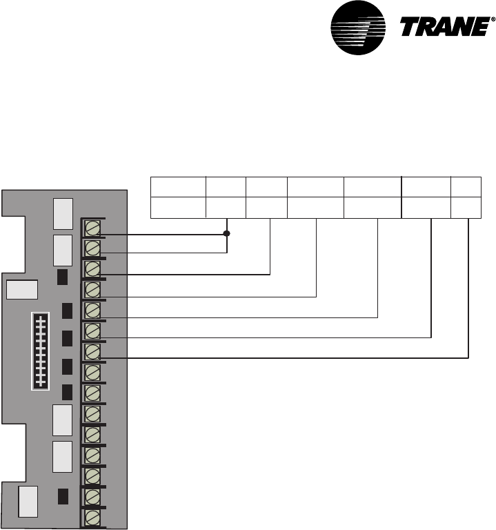
Figure 7: Binary Output Wiring for Optional Relay Board
1
2
3
4
5
6
7
8
9
10
11
12
13
14
15
NOT USED NC NO
AUX W2/O
W1 Y2 Y1 G Rh Rc
24 V*
C1
C2
Ht1
Ht22H/2C
Ht. Pump
*24 Vac from the rooftop unit. For single transformer systems,
connect Rc to Rh. For two transformer systems, connect the
cooling transformer to RC and the heating transformer to Rh.
C/O24 V* FAN
FAN
COMP1 COMP2 EM HT
Termination Board TB1
Install the Bypass Dampers and
Communicating Sensor/Bypass Control
Assembly
Install Bypass Dampers
Bypass damper(s) should be located before the first zone runs out from the
supply air duct. VariTrac dampers or supply duct branches should be
installed downstream of bypass dampers. The distance between bypass
dampers and the communicating sensor/bypass control should be two to
three equivalent duct diameters.
In a ducted return system, bypass dampers will be ducted directly to the
return air duct.
In systems with plenum return, bypass damper(s) should be ducted into the
return air riser. Confirm that sufficient relief or exhaust exists to prevent
return plenum pressurization. See Figure 8.
IMPORTANT
The use of a relief fan or backdraft damper is strongly recommended in the
return air system. This will prevent bypassed air from pressurizing the
return air duct system and spilling out of return grills into conditioned
space, especially when the unit is in economizer mode.
Getting Started
VAV-SVN03A-EN 21
Bypass Damper Wiring
The interconnect cable is pre-wired to the bypass damper and may be
lengthened if necessary.
IMPORTANT
Mounting screws must be located towards the ends of the damper when
hanging straps are used to avoid interference with the rotating damper. A
label attached to the dampers indicates the acceptable areas for mounting
screws.
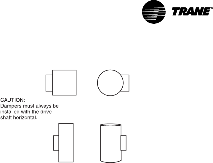
IMPORTANT
The bypass damper must be positioned to orient the drive shaft horizon-
tally. Failure to do this may result in drive train malfunction (see Figure
11).
IMPORTANT
It is important to note the airflow direction when installing dampers. A
label for this is present on each damper assembly.
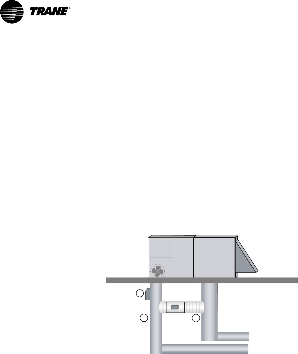
Mount the Communicating Sensor/Bypass Control
Figure 8: Mounting the Bypass Damper Communicating Sensor/Bypass
Control Assembly
Voya ger
Micro
Control
Heating and
Cooling Coils
Bypass
Damper Return
Air
Duct
Ductwork
12
3
1. Avoid high pressure turns and transitions
2. Use hard duct
3. Mount communicating Sensor/Bypass Controller
2-3 duct diameters upstream of bypass damper
The communicating sensor/bypass control is located between the supply
fan and the bypass damper in the least turbulent location possible. It is
recommended that the distance between the control and the nearest up-
stream transition be two to three equivalent duct diameters.
Bypass Damper Wiring
VAV-SVN03A-EN22
If the supply duct branches out at the riser, install the control in the largest
supply duct.
A two-inch hole is required to insert the temperature and static pressure
sensor. Use the supplied gasket to seal off air leaks. Secure the sensor to
the duct with a minimum of three sheet metal screws.
IMPORTANT
The sensor assembly should be mounted on the side of the duct to keep
the pressure transducer in a vertical orientation. Do not install horizontally
on the top or bottom of a duct.
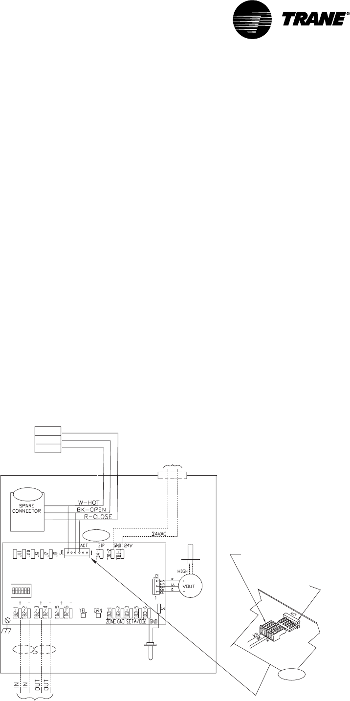
Connect the Communicating Sensor/Bypass Control
Wiring
The pre-wired interconnect cable plugs into the actuator connector inside
the control. The cable is designed to connect in one orientation only.
Refer to the diagram and connect as follows:
1Plug the red actuator connector brom the BYPS damper onto the master
damper UCM socket (ACT) as shown in Figure 9.
2If two bypass dampers are used, connect the second bypass damper’s
red actuator plus to the spare connector socket pigtailed on the first
BYPS damper cable assembly.
3If cable assembly needs to be extended, cut and splice additional wire on
the BYPS damper end of the cable.
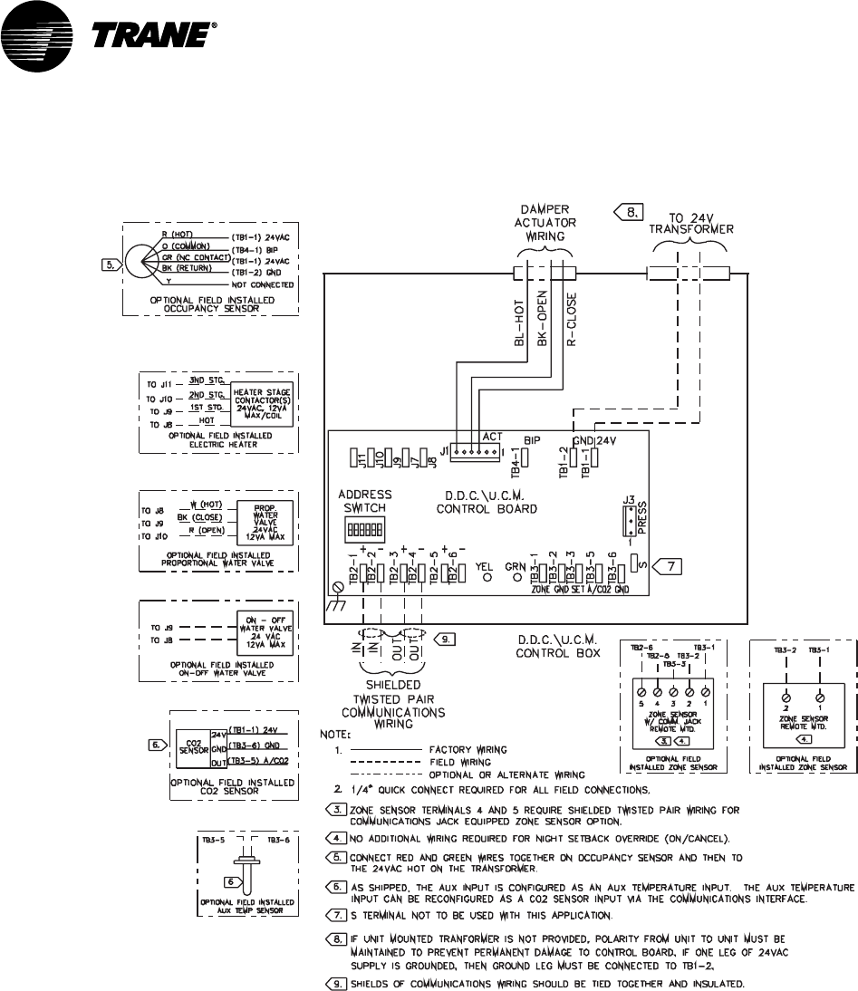
Figure 9: Wiring the Communicating Sensor/Bypass Control
Address
Switch DDC/UCM
Control Board
Shielded Twisted Pair
Communications Wiring
To NEC Class 2
24V Transformer
Load 8 VA (without actuator)
Female plug end of bypass
sensor assembly cable
Male plug end located on
DDC/UCM control board
DDC/UCM
Control Board
Step 2
Open
Close
Hot
Actuator
Step 1
Step 1
Air Supply
Temp Sensor
Static
Pressure
Port
Pressure
Transducer
Getting Started
VAV-SVN03A-EN 23
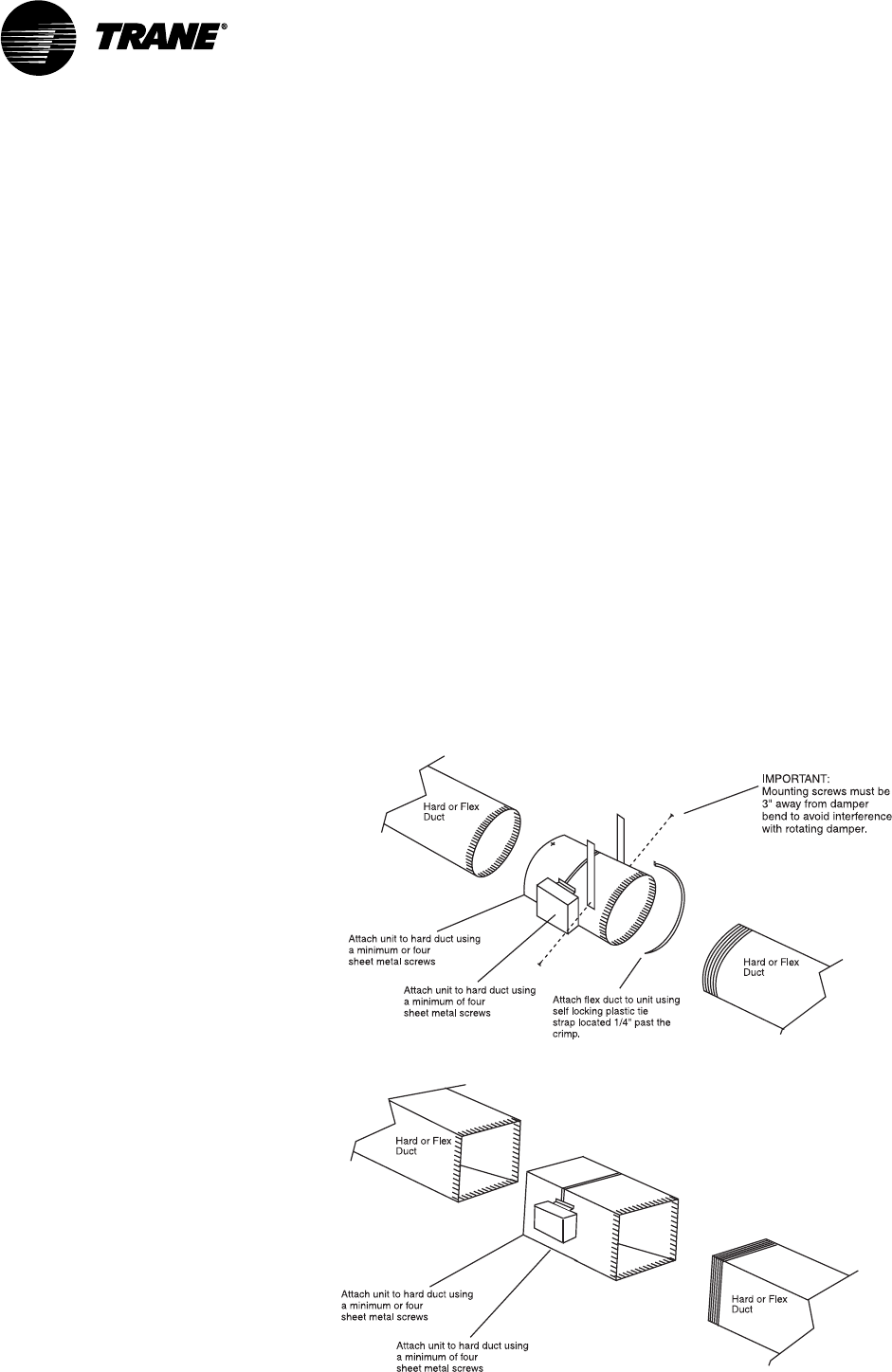
Install the VariTrac Dampers
A sketch of basic damper installation is shown in Figure 10. The damper may
be connected with hard duct or flex duct at either end.
If two bypass dampers are installed, a pigtail socket is provided on the cable
so the second damper can be plugged into the UCM.
IMPORTANT
Mounting screws must be located towards the ends of the damper when
hanging straps are used to avoid interference with the rotating damper. A
label attached to the dampers indicates the acceptable areas for mounting
screws.
IMPORTANT
It is important to note airflow direction when installing the damper. A
label for this is present on each damper assembly.
IMPORTANT
The control box on each damper must be positioned to orient the drive
shaft horizontally. Failure to do this may result in drive train malfunction.
(See Figure 11.)
Figure 10: VariTrac Damper Installation
Install the VariTrac Dampers
VAV-SVN03A-EN24
Figure 11: Proper Damper Mounting Positions
Connect UCM Wiring
Connect the power to terminals TB1-1 (24V) and TB1-2 (ground). 24 Vac is
required to power the UCM control. 20 Vac to 28 Vac is acceptable. Use 18 to
20 AWG for power wiring.
The power consumption for an auto-changeover cooling-only UCM (model
CHGR) is 10VA.
Local heat outputs are rated at 10VA maximum for each output. To
determine the total UCM power requirements, add the power consumption
of local heat to the circuit board power.
CAUTION
Use wires with copper conductors only. The use of aluminum or other
types of wire may result in overheating and equipment damage.
CAUTION
Connecting a shared UCM power supply with reversed polarity will cause
damage to the UCM, TCI, and central control panel.
CAUTION
When powering multiple UCMs from one transformer, polarity must be
maintained. Terminal TB1-1 is designated positive (+) and Terminal TB1-2 is
negative (–) to unit casing ground.
IMPORTANT
UCM control box cover must be replaced after field wiring to prevent
electromagnetic interference.
Getting Started
VAV-SVN03A-EN 25
Figure 12: UCM Wiring
Set the UCM DIP Switches
Each device connected to the VariTrac Central Control Panel must a unique
address. No two devices (of the same type) can have the same address.
Table 2 lists the address settings for UCM DIP switches connected to the
VariTrac Central Control Panel.
IMPORTANT
The UCM located in the communicating sensor/bypass control must always
be addressed as #33.
Set the UCM DIP Switches
VAV-SVN03A-EN26
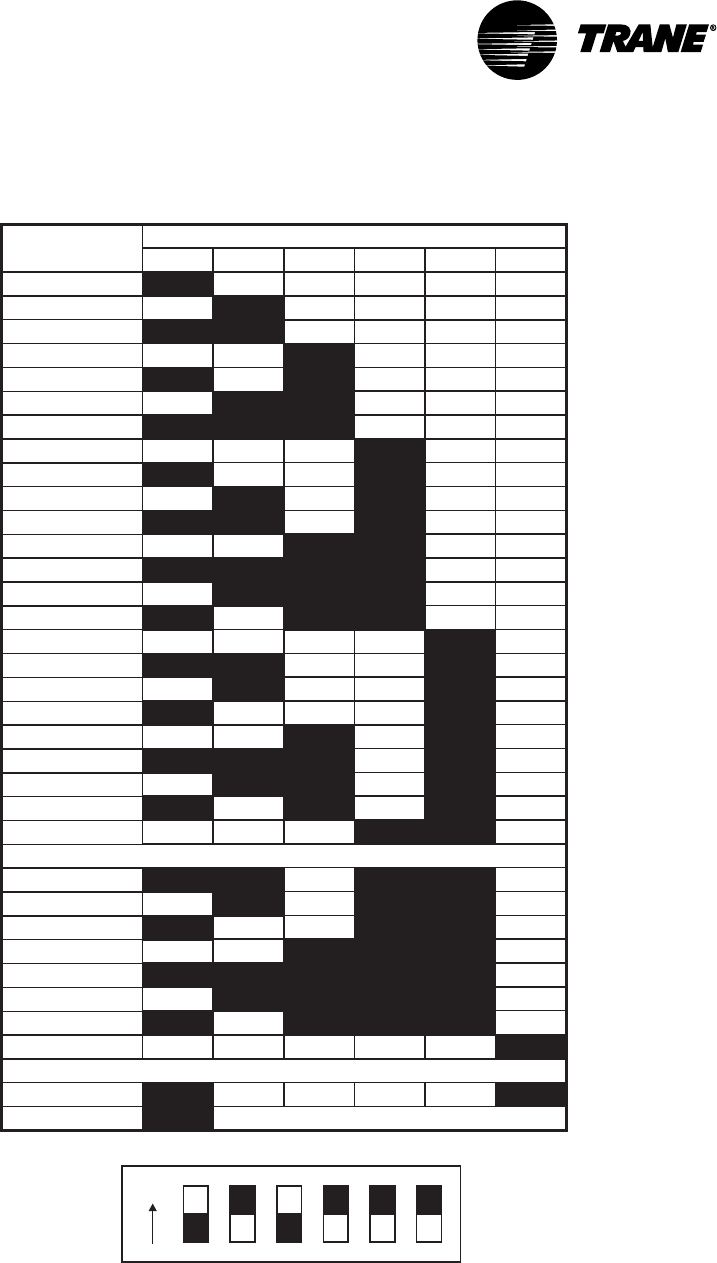
Table 2: DIP Switch Settings for UCM Damper Addresses
DIP Switch Settings
Addresses 25-32 used for Delivered VAV only
UCM
Number 12346
5
ON
ON
ON ON
ON
ON
ON ON
ON
ON
ON
ON
ON
ON
ON ON
ON
ON ON
ON
ON
ON
ON
ON
ON
ON
ON
ON
ON
ON
ON
ON
ON
ON ON
ON
ON
ON ON
ON
ON
ON
ON
ON
ON
ON ON
ON
ON
ON
ON
ON
ON
ON
ON
ON
ON
ON
ON
ON
ON
ON
ON
ON
ON
ON
ON
ON
ON
ON
ON
ON
ON
ON
ON
ON
ON
ON
ON
ON
ON
ON
ON
ON
ON
ON
ON
ON
ON
ON
ON
ON
ON
ON
ON
ON
ON
ON
ON
ON
ON
ON
ON
ON
ON
ON
= Off
01
02
03
04
05
06
07
08
09
10
11
12
13
14
15
16
17
18
19
20
21
22
23
24
25
26
27
28
29
30
31
ON ON ON ON ON
32
ON ON ON ON
33
Communicating Sensor/Bypass Control only
ON
Example of Address #5
Slaved Dampers
In some applications it may be desirable to control an additional damper
from a single UCM. The slaved damper does not require a UCM circuit
board. For this reason a model BYPS damper is paralleled directly to the
Getting Started
VAV-SVN03A-EN 27
outputs of the UCM controlling the primary damper by using the BYPS
damper cable assembly shipped with the BYPS damper.
Refer to diagram and connect as follows:
1Disconnect the red actuator plug from the master damper UCM.
2Plug the red actuator connector from the BYPS damper onto the master
damper UCM socket (ACT) as shown in Figure 13.
3Reconnect the master damper actuator’s red connector to the spare
connector socket pigtailed on the BYPS damper cable assembly.
4If cable assembly needs to be extended, cut and splice additional wire on
the BYPS damper end of the cable.
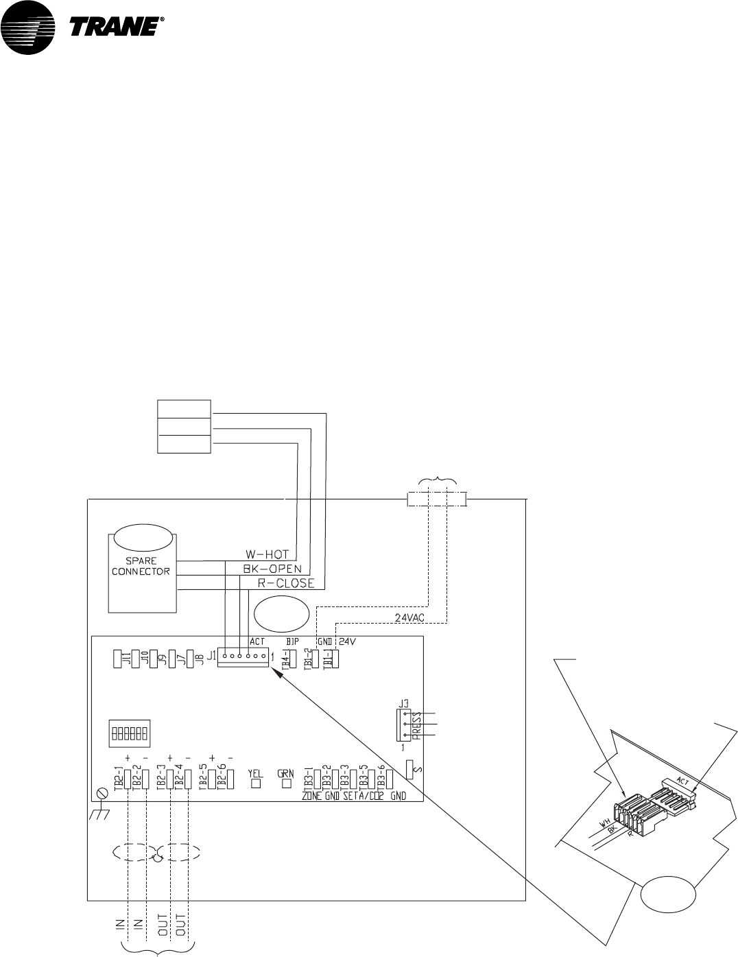
Figure 13: Wiring for Slaved Damper
Address
Switch DDC/UCM
Control Board
Shielded Twisted Pair
Communications Wiring
To NEC Class 2
24V Transformer
Load 8 VA (without actuator)
Female plug end of bypass
sensor assembly cable
Male plug end located on
DDC/UCM control board
DDC/UCM
Control Board
Step 3
Steps
1 & 2
Steps
1 & 2
Open
Close
Hot
Actuator
Slaved Dampers
VAV-SVN03A-EN28
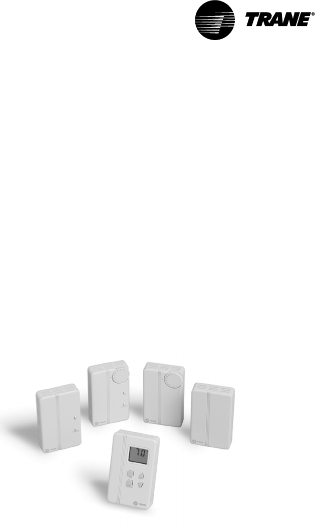
Install the Zone Temperature Sensors
Five types of zone temperature sensors are available. The sensors are
shown below in Figure 14:
•sensor with night setback override button, cancel button, and communica-
tions jack
•sensor with adjustable setpoint, night setback override button, cancel
button, and communications jack
•sensor with adjustable setpoint and communications jack
•sensor with night setback override button, cancel button, and communica-
tions jack
•sensor only
•sensor with digital display, adjustable setpoint, night setpoint override
button, cancel button, and communications jack.
Figure 14: Zone Sensor Options
Location
Proper temperature sensor location is crucial to occupant comfort. The
sensor should be placed in the most critical area of the zone where there is
free circulation of air. It should be mounted on a flat interior surface
approximately 54 inches from the floor, or as specified by the project plans
and specifications.
Avoid locating sensors in the following places:
•areas of direct sunlight
•areas blanketed by air from diffusers or subject to drafts
•surfaces with unconditioned areas behind them (such as an outside wall
or the wall of a storeroom)
Getting Started

VAV-SVN03A-EN 29
•areas near heat sources like equipment (appliances, computers, copiers,
etc.) or concealed pipes or chimneys
•dead spots behind doors, draperies, or in corners.
Mounting Standard and Digital Zone Temperature
Sensors
Zone temperature sensors consist of two basic pieces: the base and cover.
Externally adjustable versions have an external adjustment knob. To remove
the sensor cover from the base:
1Note the position of the adjustment knob (if present).
2Use a small screwdriver to gently pry the adjustment knob from the
cover.
3Before mounting a zone temperature sensor, remove zone sensor cover
by easing the tip of a small screwdriver between the base and the cover.
Gently lift the top of the screwdriver up. Do not force.
Follow these steps to replace the zone temperature sensor cover and (if
present) adjustment knob after mounting:
1Align the cover with the sides of the base.
2Press the cover toward the wall until it snaps into place.
3Align the knob to the position noted prior to its removal.
4Push the stem through the cover hole until the stem sits firmly in setpoint
potentiometer.
5Turn the knob to assure that it rotates freely through the entire range of
temperature settings.
Wall Mount
With the cover removed, feed the control wires through the rectangular
opening in the base. Follow these steps if mounting the sensor to a wall:
1Assuring that the base is level, position the back of the base over the wire
entry in the wall.
2Mark the centers of the two oblong mounting holes, then set aside the
base.
3Drill a 3/16 in. diameter hole approximately 1 in. deep at the marked
locations.
4Insert plastic anchors into the holes until they are firmly seated.
5Feed the control wires through the base and fasten the base to the wall
with the supplied mounting screws.
6Connect the control wires to the proper terminals on the temperature
sensor (See Figure 15).
7Replace the sensor cover.
Junction Box Mount
1With the cover removed, feed the control wires through the rectangular
opening in the base.
Mounting Standard and Digital Zone Temperature Sensors
VAV-SVN03A-EN30
2Using two #6-32 screws, fasten the base to the junction box’s threaded
mounting holes.
3Connect the control wires to the proper terminals on the temperature
sensor (See Figure 15).
4Replace the sensor cover.
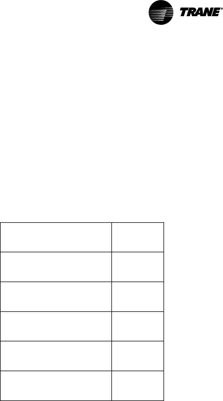
Zone Temperature Sensor Wiring
A zone temperature sensor designed specifically for UCM damper control
must control each unit. Field wiring for the zone temperature sensors must
meet local code. If local codes require enclosed conductors, the zone tem-
perature sensor wires should be installed in conduit
Do not route zone temperature sensor wires in conduit with 24V or any
other high power conducting wires.
Different numbers of conductors are required based on the zone
temperature sensor used. The following table lists the options and number
of wires required.
Table 3: Zone Sensor Options
noitpOrosneSenoZ
forebmuN
deriuqeR
seriW
1
ylnorosneS2
tniopteselbatsujdahtiwrosneS3
edirrevokcabtesthginhtiwrosneS
snottublecnacdna 2
dnatniopteselbatsujdahtiwrosneS
lecnacdnaedirrevokcabtesthgin
snottub
3
dnayalpsidDCLhtiwrosneS
thgindnatniopteselbatsujda
snottublecnacdnaedirrevokcabtes
5
2
1. Some sensors have a communication jack available as an option. If these jacks
are used, they must be wired to the UCM using a separate two-conductor,
shielded cable that meets the specification for communication link wiring. Tape
back the shield of the communication link (if used) at the zone temperature
sensor and splice the other end into the adjoining communication link shield. The
communication jacks do not need to be wired for the system to operate properly.
Getting Started
VAV-SVN03A-EN 31
2. 3 wires are required for sensor connection. 2 wires are required for 24 Vac power
connection. For wire lengths less than 75 feet, an 18 gage, 5 conductor cable may
be used. For wire lengths greater than 75 feet, use 18 gage, 2 conductor cable for
the power wiring (TB1-TB1), and 18 gage, 3 conductor cable for signal wiring
(TB2-TB3).
Figure 15: Zone Temperature Sensor Controller Wiring
Zone Temperature Sensor Wiring

VAV-SVN03A-EN32
Communication Link Wiring
The VariTrac Central Control Panel communication link (TB2-10, 11, and 12)
connects the CCP, UCM dampers, communicating sensor/bypass damper
control assembly, and Voyager/Reliatel rooftop units. Field wiring for the
communication link must meet the following requirements:
•All wiring must be in accordance with the National Electrical Code and
local codes.
•Communication link wiring must be Level 4 22 AWG twisted, shielded pair
wire (meets or exceeds Trane specifications. See wiring specifications
sections in this manual for further information).
•The maximum total wire length is 3,500 feet for the communication link.
At the VariTrac Central Control Panel, the communication link wires must be
connected to Terminals TB2-10 (+) and TB2-11 (−). Refer to Figure 17. This
connection is polarity sensitive.
IMPORTANT
Connections between lengths of link wiring should be soldered and taped.
Wire nuts are not acceptable.
CAUTION
Connecting the communication link with reversed polarity will lead to
system malfunction and possible equipment damage.
The shield on the communication link wiring must be connected to TB2-12.
The shield wire should be spliced with the shield from the next section of
communication link wiring at every junction. Tape each splice to prevent any
contact between the shield and ground. The shield should be cut and taped
back at the end of the link.
Communication link wiring cannot pass between buildings.
IMPORTANT
Improper communication link shield connections will lead to system
malfunction.
IMPORTANT
Improper communication link routing will lead to system malfunction.
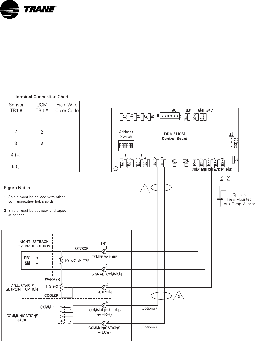
Connect UCMs on the communication link in a daisy-chain configuration.
With this configuration, it is easier to solve communication problems by
isolating portions of the communication link. See Figure 16 for an example
of a daisy-chain configuration.
Getting Started
VAV-SVN03A-EN 33
Figure 16: Daisy Chain Configuration for Communication Link Wiring
UCM Dampers
Central Control Panel
VariTrac
UCM Dampers UCM Dampers
UCM Dampers UCM Dampers UCM Dampers
Each Voyager/Reliatel Rooftop requires a Trane communications interface
(TCI) board for connection to the VariTrac Central Control Panel
communication link.
Refer to the TCI installation manual for more information on connecting a
rooftop to the communication link.
Communication Link Wiring
VAV-SVN03A-EN34
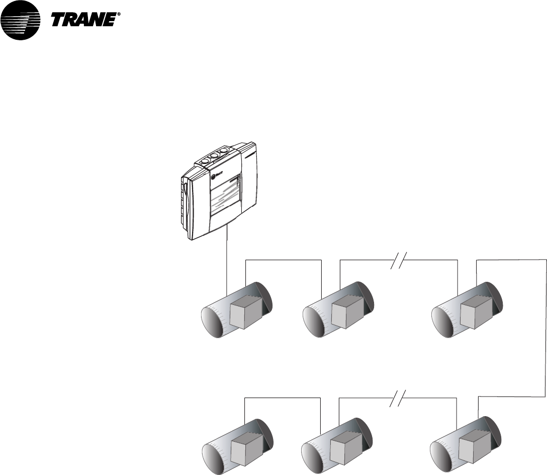
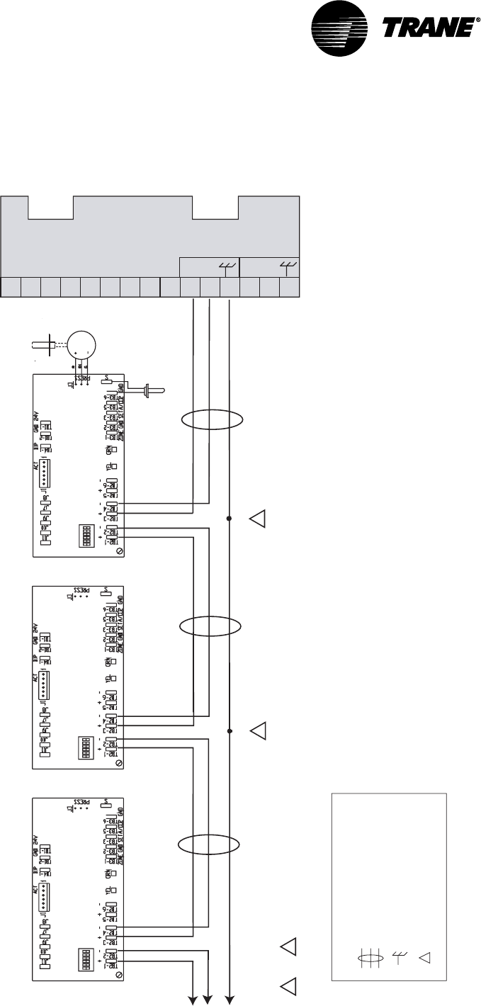
Figure 17: UCM Communication Link Wiring
1
2
3
4
5
6
7
8
9
10
11
12
13
14
15
Splice
2
Termination Board TB2
Legend
Twisted pair, shielded wire
per Trane specifications
Shield ground
=
=
Figure note
=
Figure Notes
1 Shield must be cut back and taped at last unit controller.
2 A continuous shield is required. At each unit controller, splice shield
wire and tape back to prevent grounding.
VariTrac
COMM 4
+
-
COMM 5
Zone UCM Address #2 Zone UCM Address #1
Communicating Sensor / Bypass Control
Assembly Address #33
Address
Switch DDC / UCM
Control Board
Splice
To Zone Dampers
3 through 24 2
Address
Switch
Address
Switch DDC / UCM
Control Board
DDC / UCM
Control Board
Air Supply Temp Sensor
Pressure
Transducer
Static
Pressure Port
VOUT
1 2
Note
The UCM order in this drawing is for demonstration purposes only.
No specific order is required on the Comm link.
Getting Started
VAV-SVN03A-EN 35
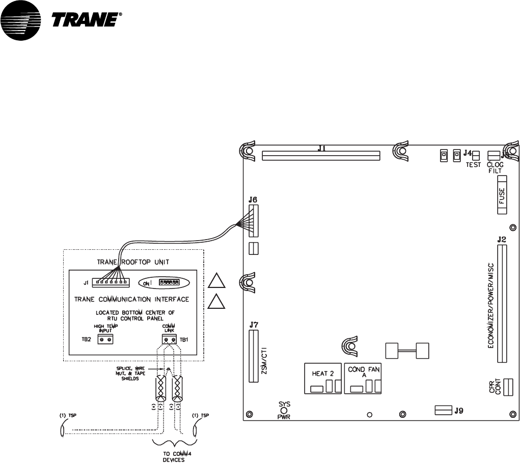
Figure 18: Voyager Communication Link Wiring
Voyager (UPC)
Unit Control Panel
Comm Termination Details for Voyager RTU
(TCI-V)
1
2
Figure Notes
1 All dip switches off.
2 Comm board to non-isolated
Comm3 or Comm4 option.
VariTrac Communications
Interface (Comm4)
Voyager Communication Link Wiring
VAV-SVN03A-EN36
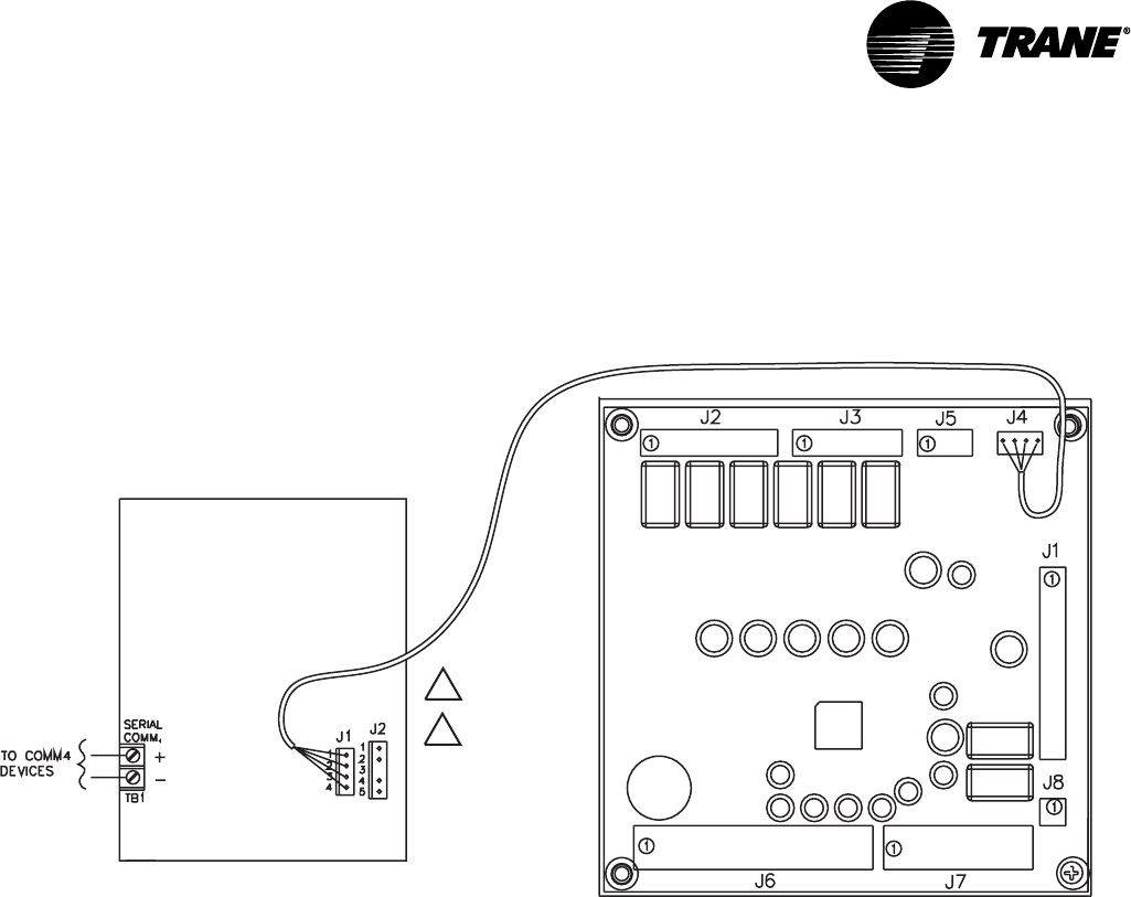
Figure 19: Precedent Communication Link Wiring
VariTrac Communications
Interface (Comm4)
Comm Termination Details for Voyager RTU
Precedent (UCP)
Unit Control Panel
(TCI-P)
Trane Communication
Interface-Precedent
1
2
Figure Notes
1 All dip switches off.
2 Comm board to non-isolated
Comm3 or Comm4 option.
Mount Main Module
After mounting and wiring the wiring base, attach the main module.
NOTE: It is not necessary to turn off 24 Vac power to the wiring base prior to mount-
ing and removing the main module.
•Verify that all the wires on the wiring base are securely fastened in place.
•Carefully line up the alignment pins on the wiring base with the back of
the main module (Figure 20).
Getting Started
VAV-SVN03A-EN 37
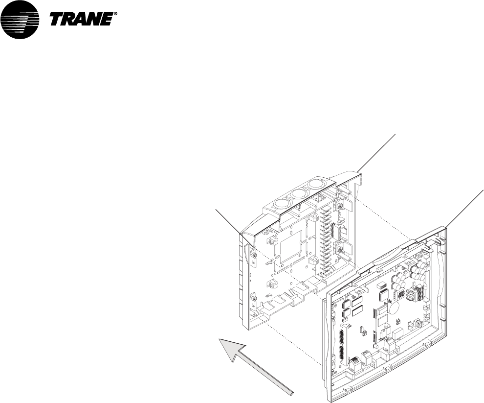
Figure 20: Mounting Main Module
Termination module
Main module
Alignment pin
(four places)
IMPORTANT
Do not use excessive force when mounting the module. If the module does
not snap easily into place, slightly reposition it on the alignment pins.
Failure to comply may cause damage to the module.
Firmly push the main module onto the wiring base until it snaps into place.
If 24 Vac is applied, the main module will start. The LEDs on the main
module will flash on and off after a few seconds
Install Operator Display (optional)
An operator display is available to provide monitoring and control of
VariTrac systems and UCM zones from one central location. The display
provides a ¼ VGA touch screen to allow the operator to interface with the
system. Temperature and system failure diagnostics and Voyager and
Precedent Rooftop unit alarms are indicated on the operator display screen
and in PC software.
NOTE: It is not necessary to turn off 24 Vac power to the wiring base prior to mount-
ing and removing the operator display.
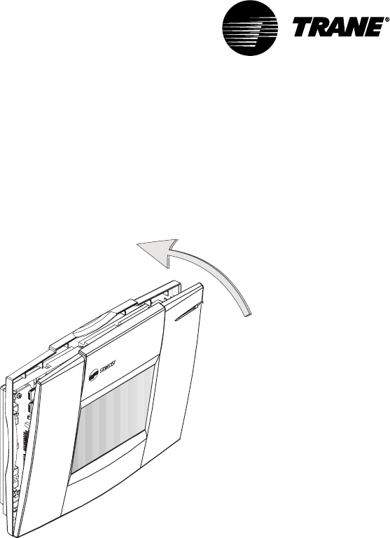
After mounting the main module, attach the operator display.
•Tilt the top of the operator display about 30 degrees towards you.
Mounting Main Module
VAV-SVN03A-EN38
•Align the three tabs on the bottom of the display with the slots in the
bottom of the main module. (Figure 21).
•Starting with the center tab, insert the tabs into the slots.
Figure 21: Install operator display
IMPORTANT
Do not use excessive force when mounting the module. If the module does
not snap easily into place, slightly reposition it on the alignment pins.
Failure to comply may cause damage to the module.
Push the top of the display module toward the main module until it snaps
into place.
If 24 Vac is applied, the operator will turn on and display data.
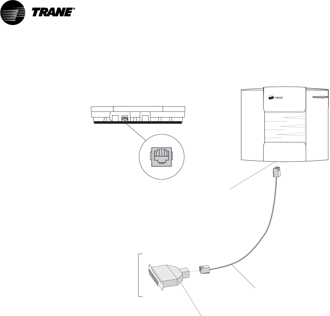
Connecting Modem Devices
Remote communications may be accomplished through a Trane building
management system or with stand-alone modem attached to a single CCP
via the RS-232 port.
A US Robotics Sportster™ fax/data external modem is recommended for
CCP applications. Modems require hardware and software configurations
for use with the CCP
Physical connection of the modem to the VariTrac Central Control Panel is
shown in Figure 22.
Getting Started
VAV-SVN03A-EN 39
Figure 22: Modular Adapters, Cable, and Connections for External
Modems
To modem
serial port
Connect RJ-12 to
25-pin male
adapter
RJ-12 port for PC
direct connection
(bottom side)
RJ-12 cable
(PN: 35914269)
(PN: 35914260)
Termination module bottom view
RJ-12 port
(PC direct connection)
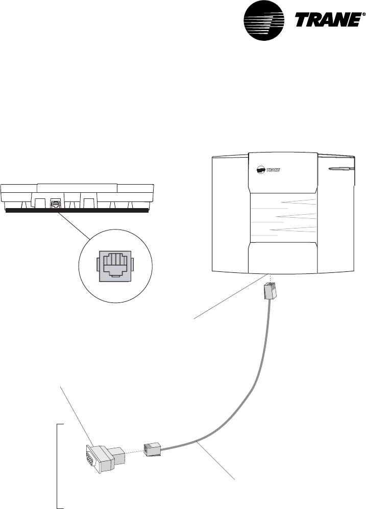
Connecting PC with VariTrac Software to CCP
The VariTrac PC Software provides a graphic user interface for VariTrac and
Delivered VAV systems. Advanced status and set-up information are avail-
able via a PC serial port connection.
Install the PC software on your PC following the instructions provided with
the software CD.
Connect your PC to the Central Control Panel as shown in Figure 23. The
connection is made using a PC serial port adapter and cable:
Adapter: DB9 female to RJ12 (PN: 3591 4262)
Cable: RJ12 to RJ12 (PN: 3591 4260)
Connecting Modem Devices
VAV-SVN03A-EN40
Figure 23: Typical VariTrac Central Control Panel to PC serial port connec-
tions
Connect RJ-12 to
9-pin female
adapter
To PC
serial port
RJ-12 port for PC
direct connection
(bottom side)
RJ-12 cable
(PN: 35914262)
(PN: 35914260)
Termination module bottom view
RJ-12 port
(PC direct connection)
Getting Started

VAV-SVN03A-EN 41
Installation Checklist
Complete this checklist as the VariTrac Central Control Panel is installed to
verify that all recommended procedures are performed. This checklist does
not replace the detailed instructions provided in the manual. Read the entire
manual carefully to become familiar with the installation procedures before
installing the unit.
Shipment
oInspect VariTrac Central Control Panel for shipping damage. File claim if
necessary.
oInspect zone dampers and accessories for shipping damage. File claim if
necessary.
Unit Location
oInstall VariTrac Central Control Panel in environment that meets tempera-
ture and humidity requirements.
oSecurely mount VariTrac Central Control Panel on wall at an accessible
location with proper clearances.
AC Power Wiring
oField installed AC power wiring complies with all applicable codes.
o24 Vac line from dedicated Class 2 transformer connected to VariTrac
Central Control Panel at TB2.
oVoltage measured at TB2-1 to TB2-2 is 20 to 30 Vac.
oAssure that a reliable earth ground has been attached to TB2-3.
Communicating Sensor/Bypass Assembly
oBypass damper(s) properly installed between supply/return ductwork per
instructions.
oCommunicating Sensor/Bypass Control mounted and wired to the
bypass damper(s).
oCommunication cable properly terminated at the Communicating Sensor/
Bypass Control and routed back to VariTrac Central Control Panel.
Input Wiring
oField installed input wiring complies with all applicable codes.
oOptional time clock and priority shutdown inputs terminated at TB2-6
through TB2-9 per instructions.
Output Wiring
oField installed output wiring complies with all applicable codes. If used,
relay wiring is terminated at TB1-1 through 11 per instructions.

VAV-SVN03A-EN42
VariTrac Dampers
oUCM dampers mounted and secure according to recommendations.
Zone Temperature Sensors
oSensors are properly mounted and wired per instructions and in the
correct space.
UCM Wiring
oUCM power is properly wired to TB1-1 and TB1-2.
NOTE: TB1-2 is COMMON (case ground) if grounded secondary transformers are
being used. Confirm polarity from one UCM to the next if more than one UCM is
being powered from a single transformer.
oConfirm voltage present between 20 Vac and 28 Vac.
oEnsure that the sensor is properly terminated.
oIf optional local heat is being used, confirm wiring per appropriate
diagram.
Communication Link Wiring
oField installed communications wiring complies with all applicable codes.
oVariTrac Central Control Panel communication link wiring to UCMs is
connected at TB2-10, TB2-11, and TB2-12 on the CCP.
oCommunication link wiring is properly terminated at each zone damper
UCM on terminals TB2-1 through TB2-6. Ensure that polarity (+ -) has
been maintained through the link.
oCommunication link wire shields spliced at each device junction and
taped to prevent contact with earth ground.
Installation Checklist

VAV-SVN03A-EN 43
System Start-Up
and Checkout
Pre-power-Up Checkout
Central Control Panel
•Measure the supply voltage to the CCP TB2-1 and TB2-2. The supply
voltage should be between 20 Vac and 30 Vac.
•Assure that a reliable ground is attached to TB2-3 on the CCP.
•Check the UCM communication link to assure that the wire designated (+)
is connected to the TB2-10 and the wire designated (–) is terminated at the
TB2-11. The shield must be connected to TB2-12.
WARNING
The following test should not be performed until all people and equipment
are clear of the air conditioning unit.
If the air handling unit is controlled by the optional field installed relay
board, check the operation of the supply fan and heating and cooling stages
by jumping the appropriate terminals of the binary output terminal block
TB1. This check assures that the wires are properly terminated at the CCP
and that the air conditioning unit is operational.
UCM
•Verify that the damper is installed with the drive shaft horizontal. See the
Installation and Wiring section of this manual for more details.
•Check to assure that all mounting screws are a minimum of three inches
away from the center damper bead if hanging straps are used. This allows
full rotation of the damper.
•Check the supply voltage at TB1-1 and TB1-2. Polarity is important. Notice
that TB1-1 is designated 24V and TB1-2 is designated ground to unit casing
ground. The acceptable voltage present is 20 Vac to 28 Vac.
CAUTION
Connecting a shared UCM power supply with reversed polarity will cause
damage to the UCM, TCI, and Central Control Panel.
When powering multiple UCMs from one transformer, polarity must be
maintained. Terminal TB1-1 is designated 24V and Terminal TB1-2 is GND to
unit casing ground.
•Verify that communications wiring is terminated at TB2-1 (+) and TB2-2 (–).
Polarity is important.
•Verify that zone sensor connections are correct as detailed in the Installa-
tion and Wiring section of this manual.

VAV-SVN03A-EN44
•Verify that the proper unit address is set on each UCM.
Occupied Mode
After the system is completely wired and installed it is ready for the initial
power-up. Upon power-up the CCP and UCMs will initiate the sequence of
events that follows.
IMPORTANT
For the CCP start-up sequence to begin, it is necessary for one UCM and a
communicating sensor/bypass control on the loop to communicate with
the CCP.
•The CCP prepares for static calibration.
•UCMs begin driving closed to perform their calibration reset.
•After calibration, the UCMs are driven to maximum position, and the
bypass begins to close.
•The “zero flow” voltage reading is taken with the fan off.
•System fan is turned on for approximately 45 seconds.
•High flow static sensor voltage is taken and stored in the CCP.
•The bypass damper is then driven to 50 percent and released.
•The UCMs are released from their MAX flow position.
•UCMs are scanned and heating/cooling callers are established.
•Fan remains on if edited to occupied fan mode “on”.
•Fan energizes if occupied fan mode is edited to “auto” and sufficient
requests are present.
•The control action of each UCM changes as appropriate.
•Heating or cooling is staged to maintain the discharge air temperature.
Unoccupied Mode
Each time the CCP enters the unoccupied mode, a static sensor self-
calibration sequence takes place.
Powering Down the System
CCP power must be disconnected to avoid unnecessary zone tagging and
personal injury during service.
UCM LEDs
Green and yellow LEDs on the circuit board help diagnose communication
or circuit board problems. Conditions indicated by the LEDs are:
System Start-Up and Checkout
VAV-SVN03A-EN 45
Green LED
NO noitarepOlamroN
FFO draobevitcefedro,rewopcaV42oN
GNIKNILB draoBevitcefeD
Yellow LED
NO ytiralopknilnoitacinummocdesreveR
FFO ytivitcaknilnoitacinummocoN
draobevitcefedro
WOLS
KNILB MCUtahtrofdednetnitonknilehtnonoitacinummoC
TSAF
KNILB PCCehthtiwdetacinummocMCUehT
UCM LEDs

VAV-SVN03A-EN46
System Start-Up and Checkout

VAV-SVN03A-EN 47
Tests and
Troubleshooting
Displayed Failures
Static Sensor Calibration Failure
If static sensor calibration fails, the CCP uses 0.50 inch wg as the static
pressure setpoint.
The zone dampers continue to control normally. Failed static sensor
calibration may indicate that the position or location of the sensor is not
correct. See mounting the communicating sensor/bypass control in this
manual. The following conditions create a static sensor calibration failure:
•No UCMs are communicating
•No UCM can be driven to MAX due to group level overrides
•Zero static reading was not in the range of 0.15 to 0.45 Vdc
•High flow static reading is less than 0.10 Vdc greater than the zero static
reading
•Fan does not run during the start-up calibration sequence
•Design static pressure value is too low
•Bypass damper(s) are operating incorrectly
Discharge Air Temperature Sensor Failure
If the discharge air temperature sensor fails, the CCP issues a priority
shutdown command:
•All zone dampers drive to maximum
•Bypass damper drives to 50 percent
•Fan and all stages of heating and cooling are de-energized
This failure appears in diagnostics on the operator display and PC software
A shorted or open temperature sensor or failed communicating sensor/
bypass control is the cause.
Communication Failure
If communications fails (no UCMs communicating), the CCP:
•De-energizes the fan and all stages of heating and cooling
•Drives the bypass to 50 percent
Individual UCM communications failures are displayed in diagnostics on the
operator display and PC software. Check all wiring connections and polarity.
See the Communications Troubleshooting section in this manual for details.

VAV-SVN03A-EN48
Zone Sensor Failure
If the zone sensor fails, the damper drives to minimum position, and its vote
is excluded.
Zone Setpoint Failure
If a setpoint fails, the UCM automatically uses the edited occupied cooling
and heating setpoints.
Auxiliary Sensor Failure
If the auxiliary sensor circuit opens, the temperature reading on the display
screen reads and a diagnostic is be displayed on the operator display and
PC software. If the auxiliary sensor is used on a stand alone UCM to
establish the control action, the UCM remains in the current control action.
Static Pressure Sensor Troubleshooting
The static pressure sensor signal enables the CCP to recognize system static
and adjust the bypass damper accordingly. If a problem exists with the
sensor or its location, the bypass damper controls with default values. If a
“failure” persists, perform the following:
1On the communicating sensor/bypass control UCM, read the voltage
across J3-1 (green wire) and J3-3 (red wire). Voltage should be between
4.50 Vdc and 5.50 Vdc.
2Read the transducer output voltage across J3-1 (green wire) and J3-2
(black wire). Voltage should be between 0.20 Vdc and 0.45 Vdc. Record the
zero flow voltage.
3Wait approximately 4 minutes after power-up for the system fan to start.
Read the transducer output voltage again across J3-1 (green wire) and
J3-2 (black wire). The difference between this voltage and the zero flow
voltage should be 0.10 Vdc minimum.
4If a defective transducer is suspected, check the output voltage with a
low-pressure source and Magnahelic gauge. Record the zero flow volt-
age. Connect a low-pressure source and Magnahelic gauge to the “hi”
port of the transducer. Input 1 inch of pressure. The voltage should be
approximately 0.750 Vdc greater than the zero flow voltage. The reading
on the voltmeter will include the zero flow voltage.
CAUTION
Do not exceed 2 inches of input pressure to avoid damaging the tranducer.
Signal change must be 0.10 Vdc minimum or a “AHU air flow” “failed”
message will be displayed
Zone, Auxiliary and System Temperature Sensor
Checkout
If temperature is reported to the UCM or CCP seems wrong use the
temperature-resistance table (Table 4) to verify the integrity of the adjustable
setpoint potentiometer or the sensor. Measure resistance across the
terminals the device is connected to. For details of terminal connections see
the Installation and Wiring section of this manual.
Tests and Troubleshooting

VAV-SVN03A-EN 49
Table 4: Temperature Resistance Table
pmeT leehwbmuhT
ecnatsiseR
rosneS
ecnatsiseR
03-
02-
01-
0
01
02
03
04
05
-
-
-
-
-
-
-
-
-
000142
000071
000121
00088
00046
00074
00053
00062
00002
55
65
75
85
95
297
277
357
337
417
85961
14561
53161
14751
85351
06
16
26
36
46
56
66
76
86
96
496
576
656
636
716
795
875
855
935
915
26941
50641
75241
81931
88531
66231
25621
64321
74321
65021
07
17
27
37
47
57
67
77
87
97
005
184
164
244
224
304
383
463
443
523
17711
39411
22211
75901
89601
54401
79101
5999
8179
7849
08
18
28
38
48
58
603
682
762
742
822
802
0629
8309
1288
8068
9938
5918
09
001
021
031
041
051
571
002
-
-
-
-
-
-
-
-
0037
0085
0083
0003
0052
0002
0031
738
Zone, Auxiliary and System Temperature Sensor Checkout

VAV-SVN03A-EN50
UCM Local Heat Checkout
Turn the adjustable zone sensor to full heating, or adjust the temperature
setpoints at the CCP.
IMPORTANT
Model DCEA local heat outputs are disabled in the heating control action.
Model DCWA local heat outputs are enabled in the heating or cooling
control action.
To check the local heat outputs:
•Disconnect any connections to Terminals J8, J9, J10, or J11.
•Place a 500 to 1000 ohm resistor between Terminals common (J8) and the
terminals (J9, J10, or J11) tested. This simulates a load condition across
the triacs within the circuit board.
•Measure the voltage between J8 (common) and the appropriate output
(J9, J10, and J11). When the heat is off, the voltage will measure between 0
and 1.5 Vac. When heat is on, voltage should read 24 Vac.
Central Control Panel Input/Output Test
Binary Input Tests
With the system in the occupied mode:
•Jump the priority shutdown input (TB2-5 and TB2-6) with a wire. The
system goes into priority shutdown.
•Remove the jumper on the priority shutdown input. Normal system
operation is restored.
•Jump the uncc input with a wire (TB2-6 and TB2-7). The system goes into
the unoccupied mode.
•Remove the jumper wire from the uncc input. The system will go into the
occupied mode.
Communicating Sensor/Bypass Control Test
The following defines the procedure necessary to test the supply air
temperature and static pressure sensor inputs to the communicating sensor/
bypass sensor control:
Supply Air Temperature Input Test
•Disconnect the supply air temperature sensor from communicating
sensor/bypass control terminals TB3-6 and TB3-7.
•System goes into priority shutdown.
•Disconnect the static sensor from J3.
•System displays static pressure failure.
•Input a resistance value between 9.4K and 10.5K across terminals TB3-6
and TB3-7. System returns to normal operation.
Tests and Troubleshooting

VAV-SVN03A-EN 51
Static Pressure Sensor Input Test
In order to perform this test a voltage between 0.25 Vdc and 0.7 Vdc must be
present at J3 pins 2 and 3. This voltage is from the pressure transducer in
the communicating sensor/bypass control. If system pressure is insufficient
to create at least .25 Vdc apply pressure to the transducer with an alternate
pressure source.
CAUTION
Do not over pressurize the transducer. The maximum pressure signal
should not exceed 2 inches H20.
When the voltage is between 0.25 Vdc and 0.7 Vdc the static pressure failure
clears.
Binary Output Test
The relay board binary outputs may be manually controlled from either the
operator display or the PC software.
Great care must be taken when manually controlling these relays. There are
NO minimum on-off timers or safe guards in effect during test mode. See
the CCP operator guide for complete description of the binary output test.
WARNING
This test can energize the fan and both stages of heating and cooling at
the rooftop unit. Before starting this test make sure that all persons, tools,
etc. are clear.
System Troubleshooting
Contact your Trane representative for problems that cannot be resolved
using these guidelines.
Static Pressure Sensor Input Test

VAV-SVN03A-EN52
Tests and Troubleshooting

VAV-SVN03A-EN 53
Delivered VAV System
Overview
What is Delivered VAV?
Delivered VAV is a small tonnage VAV system made up of three Trane prod-
uct families. It is the combination of:
•Voyager Commercial 27 ½ to 50 ton VAV Packaged Rooftop Unit
•Up to 32 VariTrane VAV boxes with DDC Controls
•VariTrac Central Control Panel with Operator Display
Delivered VAV will only work with this combination of Trane products. It will
not support any other types of equipment.
The Voyager Commercial 27 ½ to 50 ton rooftop unit must be a VAV model
with factory installed inlet guide vanes or variable frequency drive, micro-
processor controls, and Trane Communications Interface.
Delivered VAV will support up to 32 VariTrane VAV boxes with the DDC
controls option. They may be single duct boxes or fan powered boxes, and
may have a factory installed local heat option if desired.
The heart of the system is the VariTrac Central Control Panel with Operator
Display. The CCP acts as the communications hub of the system. It is
responsible for coordinating the actions of the VAV rooftop and the actions
of the VAV boxes with each other to meet the comfort requirements of the
zones.
As in any other application, the Voyager Commercial VAV unit runs the
supply fan at full constant volume whenever it goes into the heating mode,
with all the VAV boxes commanded to maximum flow. For this reason the
unit heat is only used for the Morning Warm-up and Daytime Warm-up
modes available on the Voyager Commercial unit. In both of these modes
the VAV boxes are commanded to maximum flow. If individual zone heat-
ing is required during normal daytime operation, a local heat source must
be provided at the box.
What Delivered VAV is Not
Delivered VAV is not changeover-bypass VAV. It is a true pressure indepen-
dent VAV system. The fact that we utilize the VariTrac Central Control Panel
as the heart of the system does not make it a VariTrac system. There is no
bypass damper in this system.
Additionally, Delivered VAV will only work with the combination of the
Voyager Commercial VAV unit, VariTrane VAV boxes with DDC controls, and
the VariTrac CCP with Operator Display. It will not support any other types
of equipment.
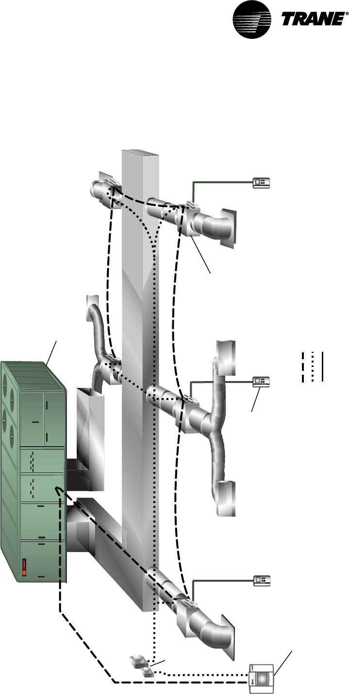
VAV-SVN03A-EN54
Figure 24: Delivered VAV System Configuration
Legend
Communications Link (2 cond, Level 4 comm wire)
24 Vac
Sensor wiring
24 Vac
Transformer
VariTrac
Central Control Panel
w/ Operator Display
VAV
Terminal
Unit
Zone
Sensor
Voyager
Commercial VAV Unit
(27 1/2 to 50 ton)
Delivered VAV System

VAV-SVN03A-EN 55
Central Control Panel
The VariTrac Central Control Panel is the central source of communications
and decision making between the individual zones and the air conditioning
unit. Connections to the CCP are:
•24 Vac power
•binary inputs for an occupied/unoccupied signal and external priority
shutdown signal (optional)
•ICS communication bus to the building automation system (optional)
•UCM communication bus to the VAV boxes and Trane Voyager commercial
27 ½ - 50 ton VAV rooftop unit
Unit Control Module (UCM)
A unit control module is mounted to each individual VAV terminal unit.
Inputs and outputs consist of the twisted shielded pair communication link,
zone temperature sensor, optional CO2 and occupancy sensors, 24 Vac
power, damper motor control, and local heat outputs. Local heat may be
duct or space mounted, and can be staged electric, pulse-width modulating
electric, and modulating or staged two-position hot water.
VariTrane VAV Terminal Units
The function of the VariTrane terminal unit in a VAV control zone is to vary
the volumetric airflow rate to the zone. VariTrane units are supplied with
microprocessor-based DDC controls. Factory-installed controls are required
with all types of terminal units.
VariTrane VAV Terminal Unit Types
Single Duct
Single duct terminal units control the volumetric flow of supply air to the
space to maintain the zone temperature at setpoint. These units are gener-
ally applied in cooling-only VAV zones that require no heat during occupied
hours. If local zone heat is necessary, it can be provided either remotely (for
example, perimeter heat) or by terminal reheat (either electric or hot water
coils).
Parallel Fan-Powered
Parallel fan-powered units are commonly used in VAV zones that require
some degree of heat during occupied hours when the primary supply air is
cool. The terminal unit fan is in parallel with the central unit fan; no primary
air from the central fan passes through the terminal unit fan. The terminal
unit fan draws air from the space return plenum.
Series Fan-Powered
Series fan-powered terminal units are used commonly in VAV zones that not
only require heat during occupied hours, but also desire constant air vol-
ume delivery. The terminal unit fan is in series with the central fan. Primary
air from the central fan always passes through the terminal unit fan.
Central Control Panel

VAV-SVN03A-EN56
The local series fan within the terminal unit operates whenever the unit is in
the occupied mode. The volume of air delivered to the VAV zone is constant,
but the temperature of the delivered air varies. As the zone requires less
cooling, the primary air damper closes. As the primary air damper closes,
the air mixture supplied to the zone contains less cool air and more warm
plenum air. Remote heat or terminal reheat can provide additional local
heating.
Auxiliary Temperature Sensor
The auxiliary temperature sensor allows the operator to monitor air tem-
perature leaving a reheat device or measure duct temperature for automatic
operation of a standalone UCM.
Zone Temperature Sensors
Five zone temperature sensor configurations are available:
•sensor only
•sensor with adjustable setpoint and communications jack
•sensor with night setback override button, cancel button, and communica-
tions jack
•sensor with adjustable setpoint, night setback override button, cancel
button, and communications jack
•sensor with digital display, adjustable setpoint, night setpoint override
button, cancel button, and communications jack
CO2 Sensor
A CO2 sensor may be connected to the UCM damper control to sense CO2
levels in the space. This signal is communicated to the CCP for demand
ventilation calculation and control.
Occupancy Sensor
A normally open occupancy sensor contact may be connected to the UCM
damper control binary input to indicate zone occupancy.
Operator Display
A ¼ VGA monochrome LCD touch screen display is installed on the CCP. This
display provides setup, diagnostic, and seven-day scheduling functions to
the system.
Delivered VAV System

VAV-SVN03A-EN 57
Getting Started
Familiarize yourself with the system components and preview the installa-
tion procedures before installing and configuring the Delivered VAV system.
Installation and configuring procedures appear in suggested order of
performance:
Installing the Central Control Panel
Refer to the following installation procedures for the CCP in this manual
•Unpacking and inspecting the components
•Wiring AC power
•Binary input wiring
NOTE: Ignore the sections referring to Installation of the CCP Relay Board and
Binary Output Wiring. Those sections do not apply to this system.
Install VariTrane VAV Terminal Units
Refer to the appropriate installation instructions shipped with the VariTrane
air terminal devices for proper installation.
Connect UCM Wiring
Refer to Connect UCM Wiring in this manual, and the appropriate installa-
tion instructions shipped with the VariTrane air terminal devices.
Set UCM DIP Switches
Refer to Set UCM DIP Switches and Table 2 in this manual, and the appropri-
ate installation instructions shipped with the VariTrane air terminal devices.
Installing Zone Temperature Sensors
Refer to Installing Zone Temperature Sensors in this manual.
Communications Link Wiring
The VariTrac Central Control Panel communication link (TB2-10, 11, and 12)
connects the CCP, VAV UCMs, and Voyager VAV rooftop unit. Field wiring for
the communication link must meet the following requirements:
•All wiring must be in accordance with the National Electrical Code and
local codes.
•Communication link wiring must be Level 4 22 AWG twisted, shielded pair
wire (meets or exceeds Trane specifications. See wiring specifications
sections in this manual for further information).
•The maximum total wire length is 3,500 feet for the communication link.

VAV-SVN03A-EN58
At the VariTrac Central Control Panel, the communication link wires must be
connected to Terminals TB2-10 (+) and TB2-11 (−). Refer to Figure 26. This
connection is polarity sensitive.
IMPORTANT
Connections between lengths of link wiring should be soldered and taped.
Wire nuts are not acceptable.
CAUTION
Connecting the communication link with reversed polarity will lead to
system malfunction and possible equipment damage.
The shield on the communication link wiring must be connected to TB2-12.
The shield wire should be spliced with the shield from the next section of
communication link wiring at every junction. Tape each splice to prevent any
contact between the shield and ground. The shield should be cut and taped
back at the end of the link.
Communication link wiring cannot pass between buildings.
IMPORTANT
Improper communication link shield connections will lead to system
malfunction.
IMPORTANT
Improper communication link routing will lead to system malfunction.
Connect UCMs on the communication link in a daisy-chain configuration.
With this configuration, it is easier to solve communication problems by
isolating portions of the communication link. See Figure 25 for an example
of a daisy-chain configuration.
Getting Started
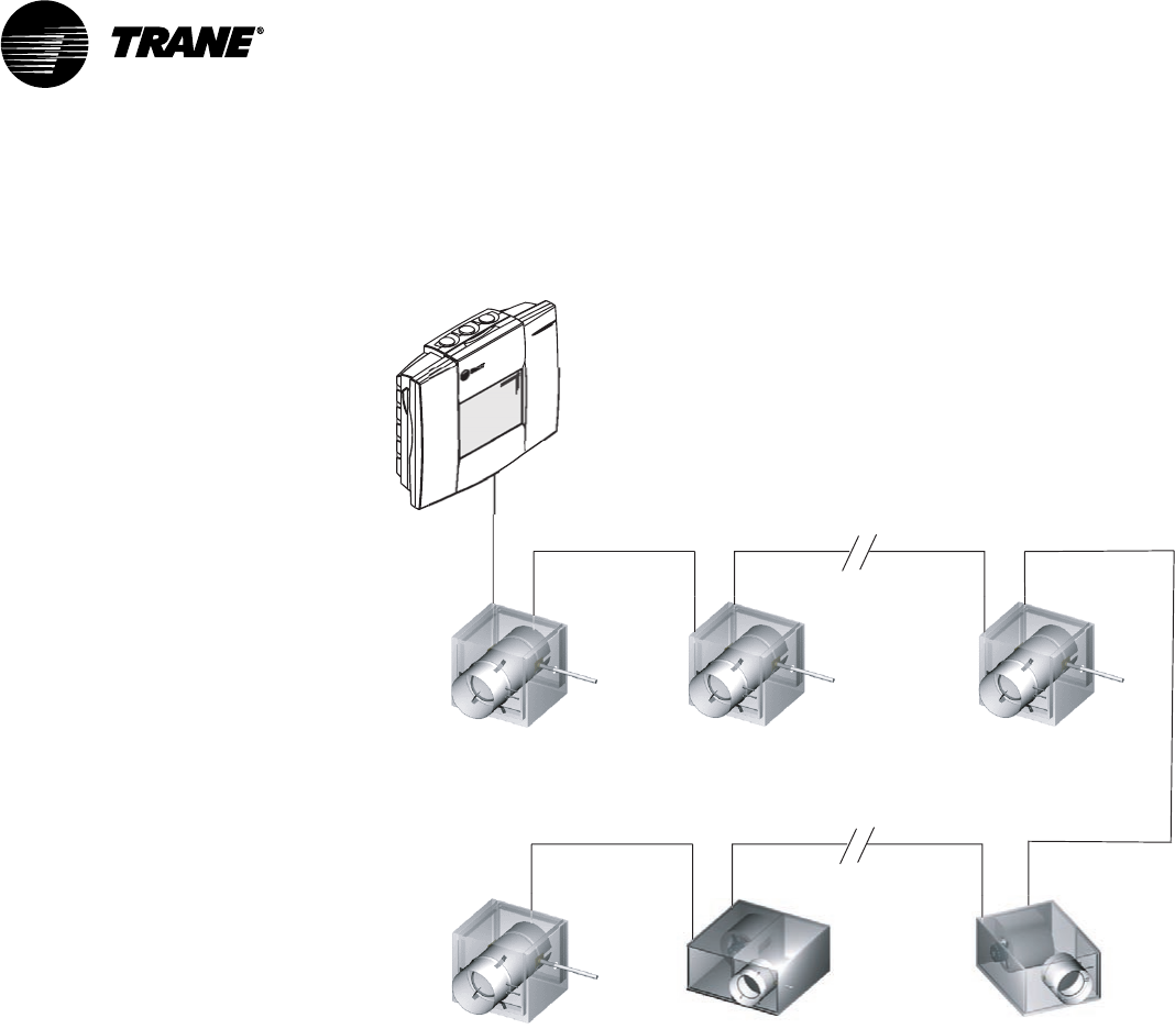
VAV-SVN03A-EN 59
Figure 25: Daisy Chain Configuration for Communication Link Wiring
VAV Terminal Unit
VAV Terminal Unit VAV Terminal Unit VAV Terminal Unit
VAV Terminal Unit VAV Terminal Unit
Central Control Panel
VariTrac
with Operator Display
Each Voyager VAV Rooftop requires a Trane communications interface (TCI)
board for connection to the VariTrac Central Control Panel communication
link.
Refer to the TCI installation manual for more information on connecting a
rooftop to the communication link.
Daisy Chain Configuration for Communication Link Wiring
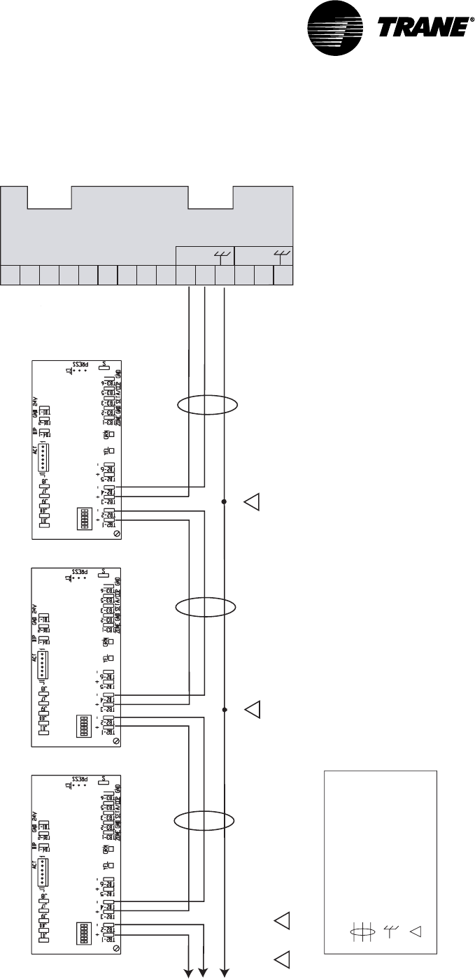
VAV-SVN03A-EN60
Figure 26: UCM Communication Link Wiring
1
2
3
4
5
6
7
8
9
10
11
12
13
14
15
Splice
2
Termination Board TB2
Legend
Twisted pair, shielded wire
per Trane specifications
Shield ground
=
=
Figure note
=
Figure Notes
1 Shield must be cut back and taped at last unit controller.
2 A continuous shield is required. At each unit controller, splice shield
wire and tape back to prevent grounding.
VariTrac
COMM 4
+
-
COMM 5
VAV UCM Address #3 VAV UCM Address #2 VAV UCM Address #1
Address
Switch DDC / UCM
Control Board
Splice
To VAV Terminal Units
4 through 32 2
Address
Switch
Address
Switch DDC / UCM
Control Board
DDC / UCM
Control Board
1 2
Note
The UCM order in this drawing is for demonstration purposes only.
No specific order is required on the Comm link.
Getting Started
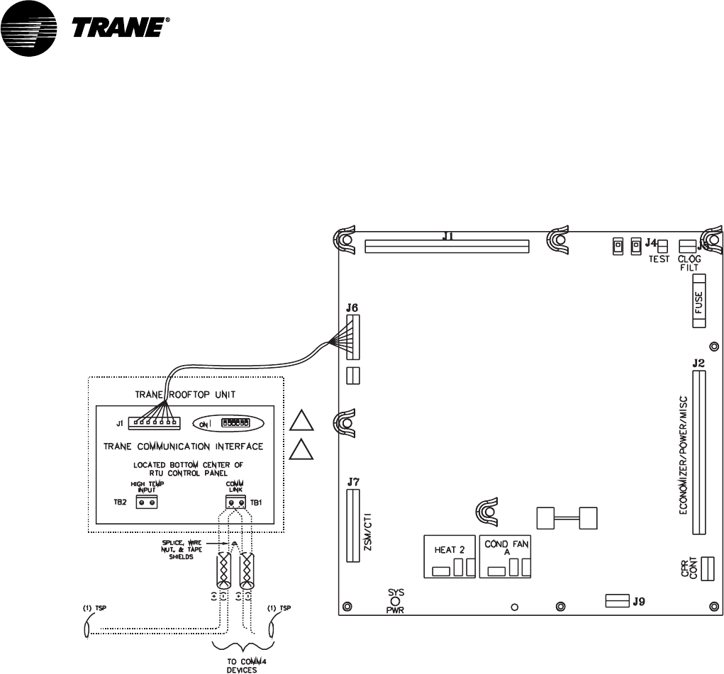
VAV-SVN03A-EN 61
Figure 27: Voyager Communication Link Wiring
Voyager (UPC)
Unit Control Panel
Comm Termination Details for Voyager RTU
(TCI-V)
1
2
Figure Notes
1 All dip switches off.
2 Comm board to non-isolated
Comm3 or Comm4 option.
VariTrac Communications
Interface (Comm4)
Voyager Communication Link Wiring

VAV-SVN03A-EN62
Getting Started

VAV-SVN03A-EN 63
Installation Checklist
Complete this checklist as the VariTrac Central Control Panel is installed to
verify that all recommended procedures are performed. This checklist does
not replace the detailed instructions provided in the manual. Read the entire
manual carefully to become familiar with the installation procedures before
installing the unit.
Shipment
oInspect VariTrac Central Control Panel for shipping damage. File claim if
necessary.
oInspect VAV terminal units and accessories for shipping damage. File
claim if necessary.
Unit Location
oInstall VariTrac Central Control Panel in environment that meets tempera-
ture and humidity requirements.
oSecurely mount VariTrac Central Control Panel on wall at an accessible
location with proper clearances.
AC Power Wiring
oField installed AC power wiring complies with all applicable codes.
o24 Vac line from dedicated Class 2 transformer connected to VariTrac
Central Control Panel at TB2.
oVoltage measured at TB2-1 to TB2-2 is 20 to 30 Vac.
oAssure that a reliable earth ground has been attached to TB2-3.
Input Wiring
oField installed input wiring complies with all applicable codes.
oOptional time clock and priority shutdown inputs terminated at TB2-6
through TB2-9 per instructions.
VariTrane Terminal Units
oAir terminal units mounted and secure according to recommendations.
Zone Temperature Sensors
oSensors are properly mounted and wired per instructions and in the
correct space.
UCM Wiring
oUCM power is properly wired to TB1-1 and TB1-2.
NOTE: TB1-2 is COMMON (case ground) if grounded secondary transformers are
being used. Confirm polarity from one UCM to the next if more than one UCM is
being powered from a single transformer.

VAV-SVN03A-EN64
oConfirm voltage present between 20 Vac and 28 Vac.
oEnsure that the sensor is properly terminated.
oIf optional local heat is being used, confirm wiring per appropriate
diagram.
Communication Link Wiring
oField installed communications wiring complies with all applicable codes.
oVariTrac Central Control Panel communication link wiring to VAV UCMs
and Voyager VAV rooftop unit is connected at TB2-10, TB2-11, and TB2-12
on the CCP.
oCommunication link wiring is properly terminated at each zone damper
UCM on terminals TB2-1 through TB2-6. Ensure that polarity (+ -) has
been maintained through the link.
oCommunication link wire shields spliced at each device junction and
taped to prevent contact with earth ground.
Completing Central Control Panel
Assembly
Mount Main Module
Refer to Mount Main Module instructions in this manual.
Install Operator Display
Refer to Install Operator Display instructions in this manual. The Operator
Display is required for the Delivered VAV system to function.
Connecting Modem Devices
Refer to Connecting Modem Devices instructions in this manual.
Installation Checklist
Literature Order Number VAV-SVN03A-EN
File Number SV-AH-VAV-000-SVN03A-EN-0602
Supersedes VADA-IN-2
Stocking Location La Crosse
Trane has a policy of continuous product and product data improvement and reserves the right to change
design and specifications without notice. Only qualified technicians should perform the installation and
servicing of equipment referred to in this publication.
Trane
An American Standard Company
www.trane.com
For more information contact
your local district office or
e-mail us at comfort@trane.com
