Trane Varitrac Dampers Programming Guide VAV SVP01A EN VV550 LonTalk Controller
Trane-Single-Duct-Programming-Guide-684328 trane-single-duct-programming-guide-684328
Trane-Round-In-Round-Out-Programming-Guide-684317 trane-round-in-round-out-programming-guide-684317
Trane-Fan-Powered-Series-Terminal-Programming-Guide-684349 trane-fan-powered-series-terminal-programming-guide-684349
Trane-Fan-Powered-Parallel-Terminal-Programming-Guide-684360 trane-fan-powered-parallel-terminal-programming-guide-684360
Trane-Fan-Powered-Low-Height-Series-Programming-Guide-684371 trane-fan-powered-low-height-series-programming-guide-684371
2015-04-02
: Trane Trane-Varitrac-Dampers-Programming-Guide-684395 trane-varitrac-dampers-programming-guide-684395 trane pdf
Open the PDF directly: View PDF ![]() .
.
Page Count: 116 [warning: Documents this large are best viewed by clicking the View PDF Link!]
May 2010 VAV-SVP01A-EN
Installation
Operation
Programming
VAV VV550 LonTalk
Controller

© 2010 Trane All rights reserved VAV-SVP01A-EN
Warnings, Cautions and Notices
Warnings, Cautions and Notices. Note that warnings, cautions and notices appear at
appropriate intervals throughout this manual. Warnings are provided to alert installing contractors
to potential hazards that could result in personal injury or death. Cautions are designed to alert
personnel to hazardous situations that could result in personal injury, while notices indicate a
situation that could result in equipment or property-damage-only accidents.
Your personal safety and the proper operation of this machine depend upon the strict observance
of these precautions.
WARNING
This equipment is to be serviced/installed by qualified personnel ONLY. Under NO
circumstances should an unqualified person service/install it. Servicing/installing this
equipment is a job requiring specific knowledge and MUST be left to a professional. It involves
working with hazardous components that are potentially life threatening if not handled
properly. Improperly installed, adjusted or altered equipment by an unqualified person could
result in death or serious injury.
WARNING
Personal Protective Equipment (PPE) Required!
Installing/servicing this unit could result in exposure to electrical, mechanical and chemical
hazards.
• Before installing/servicing this unit, technicians MUST put on all Personal Protective
Equipment (PPE) recommended for the work being undertaken. ALWAYS refer to appropriate
MSDS sheets and OSHA guidelines for proper PPE.
• When working with or around hazardous chemicals, ALWAYS refer to the appropriate MSDS
sheets and OSHA guidelines for information on allowable personal exposure levels, proper
respiratory protection and handling recommendations.
• If there is a risk of arc or flash, technicians MUST put on all necessary Personal Protective
Equipment (PPE) in accordance with NFPA70E for arc/flash protection PRIOR to servicing the
unit.
Failure to follow recommendations could result in death or serious injury.
ATTENTION: Warnings, Cautions and Notices appear at appropriate sections throughout
this literature. Read these carefully.
WARNING: Indicates a potentially hazardous situation which, if not avoided, could
result in death or serious injury.
CAUTION: Indicates a potentially hazardous situation which, if not avoided, could
result in minor or moderate injury. It could also be used to alert against unsafe practices.
NOTICE: Indicates a situation that could result in equipment or property-damage-only
accidents.

VAV-SVP01A-EN 3
Warnings, Cautions and Notices
WARNING
Electrocution and Fire Hazards with Improperly Installed and Grounded
Field Wiring!
Improperly installed and grounded field wiring poses FIRE & ELECTROCUTION hazards. To avoid
these hazards, you MUST follow requirements for field wiring installation and grounding as
described in NEC and your local/state electrical codes. All field wiring MUST be performed by
qualified personnel. Failure to follow these requirements could result in death or serious injury.
Overview of Manual
Note: One copy of this document ships inside the control panel of each unit and is customer
property. It must be retained by the unit's maintenance personnel.
This booklet describes proper installation, operation, and maintenance procedures for delivered
air systems. By carefully reviewing the information within this manual and following the
instructions, the risk of improper operation and/or component damage will be minimized. It is
important that periodic maintenance be performed to help assure trouble free operation. A
maintenance schedule is provided at the end of this manual. Should equipment failure occur,
contact a qualified service organization with qualified, experienced HVAC technicians to properly
diagnose and repair this equipment.

4 VAV-SVP01A-EN
Table of Contents
General Information . . . . . . . . . . . . . . . . . . . . . . . . . . . . . . . . . . . . . . . . . . . . . . . . . . . . 6
Chapter Overview . . . . . . . . . . . . . . . . . . . . . . . . . . . . . . . . . . . . . . . . . . . . . . . . . . 6
Unit Control Module VAV VV550 Controller . . . . . . . . . . . . . . . . . . . . . . . . . . . 6
Specifications . . . . . . . . . . . . . . . . . . . . . . . . . . . . . . . . . . . . . . . . . . . . . . . . . . . . . 7
VV550 Enhancements . . . . . . . . . . . . . . . . . . . . . . . . . . . . . . . . . . . . . . . . . . . . . . 8
VV550 Features . . . . . . . . . . . . . . . . . . . . . . . . . . . . . . . . . . . . . . . . . . . . . . . . . . . . 9
Shipping & Storage . . . . . . . . . . . . . . . . . . . . . . . . . . . . . . . . . . . . . . . . . . . . . . . 11
Data Lists . . . . . . . . . . . . . . . . . . . . . . . . . . . . . . . . . . . . . . . . . . . . . . . . . . . . . . . . 12
VAV Start Up/Check Out Procedure . . . . . . . . . . . . . . . . . . . . . . . . . . . . . . . . . . . . . . 14
Chapter Overview . . . . . . . . . . . . . . . . . . . . . . . . . . . . . . . . . . . . . . . . . . . . . . . . . 14
VV550 Pre-Power Check-Out . . . . . . . . . . . . . . . . . . . . . . . . . . . . . . . . . . . . . . . . 14
VV550 Power Wiring . . . . . . . . . . . . . . . . . . . . . . . . . . . . . . . . . . . . . . . . . . . . . . 15
Light Emitting Diode (LED) Operations . . . . . . . . . . . . . . . . . . . . . . . . . . . . . . . 16
Communication Wiring . . . . . . . . . . . . . . . . . . . . . . . . . . . . . . . . . . . . . . . . . . . . 19
Wireless Zone Sensor . . . . . . . . . . . . . . . . . . . . . . . . . . . . . . . . . . . . . . . . . . . . . 27
VAV VV550 Controller Programming and Operation . . . . . . . . . . . . . . . . . . . . . . 42
Chapter Overview . . . . . . . . . . . . . . . . . . . . . . . . . . . . . . . . . . . . . . . . . . . . . . . . . 42
Accessing Rover/Comm5 LonTalk . . . . . . . . . . . . . . . . . . . . . . . . . . . . . . . . . . . 42
VV550 Controller Device Home Tabs: At a Glance . . . . . . . . . . . . . . . . . . . . . 44
Entering and Exiting the Service Mode . . . . . . . . . . . . . . . . . . . . . . . . . . . . . . 51
Overriding VAVs . . . . . . . . . . . . . . . . . . . . . . . . . . . . . . . . . . . . . . . . . . . . . . . . . . 51
VAV VV550 Controller Device Home Tabs: Instructions . . . . . . . . . . . . . . . . . . . . 54
Chapter Overview . . . . . . . . . . . . . . . . . . . . . . . . . . . . . . . . . . . . . . . . . . . . . . . . . 54
Configuration . . . . . . . . . . . . . . . . . . . . . . . . . . . . . . . . . . . . . . . . . . . . . . . . . . . . 54
Setpoints Tab . . . . . . . . . . . . . . . . . . . . . . . . . . . . . . . . . . . . . . . . . . . . . . . . . . . . 54
Unit Tab . . . . . . . . . . . . . . . . . . . . . . . . . . . . . . . . . . . . . . . . . . . . . . . . . . . . . . . . . 57
Setup Tab . . . . . . . . . . . . . . . . . . . . . . . . . . . . . . . . . . . . . . . . . . . . . . . . . . . . . . . . 59
Inputs Tab . . . . . . . . . . . . . . . . . . . . . . . . . . . . . . . . . . . . . . . . . . . . . . . . . . . . . . . 61
Outputs Tab . . . . . . . . . . . . . . . . . . . . . . . . . . . . . . . . . . . . . . . . . . . . . . . . . . . . . . 63
Test Tab . . . . . . . . . . . . . . . . . . . . . . . . . . . . . . . . . . . . . . . . . . . . . . . . . . . . . . . . . 64
Other Tab . . . . . . . . . . . . . . . . . . . . . . . . . . . . . . . . . . . . . . . . . . . . . . . . . . . . . . . . 65
Overrides . . . . . . . . . . . . . . . . . . . . . . . . . . . . . . . . . . . . . . . . . . . . . . . . . . . . . . . . 66
Sequence of Operations . . . . . . . . . . . . . . . . . . . . . . . . . . . . . . . . . . . . . . . . . . . . . . . . 67
Chapter Overview . . . . . . . . . . . . . . . . . . . . . . . . . . . . . . . . . . . . . . . . . . . . . . . . . 67
Calibration . . . . . . . . . . . . . . . . . . . . . . . . . . . . . . . . . . . . . . . . . . . . . . . . . . . . . . . 67

VAV-SVP01A-EN 5
Occupancy Modes . . . . . . . . . . . . . . . . . . . . . . . . . . . . . . . . . . . . . . . . . . . . . . . . 68
Space Temperature Control: Single Duct Units . . . . . . . . . . . . . . . . . . . . . . . . 69
Space Temperature Control: Fan-Powered Units . . . . . . . . . . . . . . . . . . . . . . 72
Ventilation Flow Control . . . . . . . . . . . . . . . . . . . . . . . . . . . . . . . . . . . . . . . . . . . 74
Flow Tracking . . . . . . . . . . . . . . . . . . . . . . . . . . . . . . . . . . . . . . . . . . . . . . . . . . . . 76
Air and Water Balancing . . . . . . . . . . . . . . . . . . . . . . . . . . . . . . . . . . . . . . . . . . . . . . . 78
Chapter Overview . . . . . . . . . . . . . . . . . . . . . . . . . . . . . . . . . . . . . . . . . . . . . . . . . 78
Air Balancing . . . . . . . . . . . . . . . . . . . . . . . . . . . . . . . . . . . . . . . . . . . . . . . . . . . . . 78
Rover Air and Water Balancing Tool . . . . . . . . . . . . . . . . . . . . . . . . . . . . . . . . . 79
Troubleshooting . . . . . . . . . . . . . . . . . . . . . . . . . . . . . . . . . . . . . . . . . . . . . . . . . . . . . . . 83
Chapter Overview . . . . . . . . . . . . . . . . . . . . . . . . . . . . . . . . . . . . . . . . . . . . . . . . . 83
Diagnosing the Problem . . . . . . . . . . . . . . . . . . . . . . . . . . . . . . . . . . . . . . . . . . . 83
Troubleshooting Procedures . . . . . . . . . . . . . . . . . . . . . . . . . . . . . . . . . . . . . . . 87
Trane/Honeywell Proportional Valve Check Out Procedures . . . . . . . . . . . 105

6 VAV-SVP01A-EN
General Information
Chapter Overview
This chapter contains information about the following:
• Unit Control Module VAV VV550 Controller
• Specifications
• VAV VV550 Controller Enhancements
• VAV VV550 Controller Features
• Shipping & Storage
• Data Lists
Unit Control Module VAV VV550 Controller
The VV550 is a microprocessor-based, Direct Digital Controller (DDC) for the (Variable Air Volume)
VAV terminal unit. Units have been made with either pneumatic, analog electronic, or
microprocessor controls (DDC VAV). This manual discusses only terminal units with Comm 5 VAV
VV550 DDC Controller. Factory installed DDC/VAV controls are available with all single duct
terminal units, dual duct units, as well as parallel fan-powered and series fan-powered units. Two
VAV VV550 Controllers are required for dual duct units (one for the heating duct and one for the
cooling duct) and another application requiring to controllers is Flow tracking (one unit controller
is programmed from the factory with the Space temperature program and the other is downloaded
with the Flow tracking program.
The VAV VV550 Controller can be configured from the factory with three different application
programs. The VAV VV550 Controller programmed for space temperature control modulates a
VAV's damper blade based on a zone temperature, measured airflow, and set points to
continuously control conditioned air delivery to the space. The volume of incoming air is
monitored and the damper adjusts to provide accurate control independent of the duct pressure.
The damper modulates between operator set points depending on space conditions. Additionally,
fan and heat outputs may be energized depending on the application.
The VAV VV550 Controller programmed for ventilation flow control is applied to a VAV terminal and
used to temper cold outdoor air (OA) that is brought into a building for ventilation purposes. The
tempered air is intended to supply an air-handling unit (AHU), which provides comfort control to
the zones it is serving. The VAV terminal supplies the correct amount of ventilation air and, when
reheat is added, tempers the ventilation air to reduce the load on the air handler by sensing the
discharge air temperature of VAV unit.
The VAV VV550 Controller programmed for Flow Tracking Control (FTC) has two VAV VV550
Controllers working together to provide flow tracking control. One VAV VV550 controller is
programmed from the factory with the Space temperature program and the other is downloaded
with the Flow tracking program. The space temperature controller airflow output is bound to the
flow tracking controller airflow setpoint input. The flow tracking controller adds the configured
airflow tracking offset (positive or negative) to the airflow setpoint (communicated airflow setpoint)
and controls the airflow to this setpoint.
The VAV VV550 Controller utilizes an FTT-10A Free Topology transceiver, which supports non-
polarity sensitive, free topology wiring, which allows the system installer to utilize star, bus, and
loop architectures. Available inputs include a twisted/shielded communication link, zone sensor,
auxiliary temperature sensor (optional), and Occupy/Unoccupied Sensor (optional), and 24VAC
power.

VAV-SVP01A-EN 7
General Information
Specifications
Power Requirements
The UCM VV550 requires 18-32 Vac (24VAC nominal), 50/60 Hz, and up to 50 VA, depending on the
number of heat outputs (stages), which consume 10 VA each.
Operating Environments - VAV VV550 Controller
32° to 140°F (0° to 60°C), 5% to 90% relative humidity, non-condensing
Storage Environments - VAV VV550 Controller
-40° to 185°F (-40° to 85°C), 5% to 90% relative humidity, non-condensing
From 5 to 95% non-condensing
Relative humidity:
From 5 to 95% non-condensing
Analog Inputs
Space temperature; thermistor: 10 kΩ@ 77°F (25°C) From 14 to 122°F (-10 to 50°C)
Space setpoint; potentiometer: 1 kΩ From 50 to 90°F (-10 to 32.2°C)
Primary/discharge air temperature; thermistor: 10 kΩ@ 77°F (25°C) From -40 to 212°F (-40 to 100°C)
Primary air flow; pressure transducer: From 0 to 2 in. water (0 to 498 Pa)
Binary Input
Occupancy or generic (dry contact)
Binary Outputs
Air valve close: maximum output rating: 12 VA
Air valve open: maximum output rating: 12 VA
Heat stage 1: maximum output rating: 12 VA
Heat stage 2: maximum output rating: 12 VA
Heat stage 3/Fan on/off: maximum output rating: 12 VA
Agency Listings/Compliance
VAV VV550 Controller:
UL 873 and CSA C22.2 No. 24-93:
Temperature Indicating and Regulating
Equipment
VAV VV551 Controller:
UL-916-PAZX-energy management
CUL-C22.2-signal devices-Canada
UL 94-5V (UL flammability rating for plenum use)
FCC Part 15, Class A
CE marked
Mounting
Typically, the VAV VV550 Controller is factory installed. However, the VAV VV550 Controller is
available with retrofit kits, in which case it must be field installed, and it’s named VV551.
Tracer Summit and VV550 Communications Link Wiring
Use 22 AWG Level 4 unshielded communication wire for most Comm5 installations. Limit Comm5
links to 4,500 ft and 60 devices maximum (without a repeater). Use one repeater for an additional
4,500 ft, 60 devices, and 8 communication stubs. Refer to Chapters 2 and 3 for further information
about wire selection.

8 VAV-SVP01A-EN
General Information
VV550 Enhancements
Controller Interface Flexibility
VV550 controller allows VAV units to communicate on a Trane Comm5 or LonTalk. This controller
works in standalone mode, peer-to-peer with one or more other units, or when connected to a Trane
Tracer Summit or a 3rd party building automation system that supports LonTalk.
Manual Test Function
The VV550 controller includes a manual test button that allows the field technician to manually
exercise the outputs of the controller. This feature is simple enough for the electrician to use to
check valve operation. Though this feature is standard on other Comm5 controllers, the feature is
not available on the VAV VV550 Controller.
Flow Tracking
The VV550 controller has been designed with the ability to be applied in flow tracking applications.
This allows the controller to pair with one of its peers to mirror the flow if that lead box, with or
without an offset (positive or negative static pressure as desired).
Ventilation Flow Control w/ Tempering
The VV550 controller has been designed with the ability to be applied in ventilation flow control
applications. These applications pair a fresh air unit with ventilation boxes to provide fresh
(tempered) air to a floor/area. This feature also includes a freeze protection sequence to protect the
hot water reheat coil from low supply air temperatures.
Auto-commissioning Sequence
The VV550 controller has been designed with an auto-commissioning sequence. With a discharge
air temperature sensor, this feature exercises the air valve, fan, and heat in the box and records the
temperature before and after the action. This allows the installer to more easily checkout the
operation of the box and commission by exception.
Automatic Calibration
The VV550 controller has been designed to automatically calibrate the flow transducer each time
the box transitions to unoccupied. This eliminates the need to initiate/schedule calibration for most
installations. The exception is 24/7 sites, in which case Tracer Summit can be used to initiate/
schedule calibration.
Temporary Heat (Construction Mode)
Upon reset (and power-up) if the controller does not detect a valid space temperature the controller
will provide temporary heat by driving the air valve to the heating maximum position. Of course,
the box will only provide heat if hot air is being provided by the air-handling unit.
Local versus Remote Reheat Flexibility
The controller can be configured to have local and/or remote heat. Plus, configuration flexibility is
offered that allows the installer to select whether local or remote heat has priority.
Zone Sensor Air Balancing
When applied with a Trane zone sensor module that includes a setpoint thumbwheel and ON and
CANCEL buttons, the controller offers a zone sensor air-balancing feature. This feature allows the
balancing contractor to drive the box to either its minimum or maximum flow setting by turning
the setpoint thumbwheel on the zone sensor module. Then, the balancing contractor can calibrate
the flow reading by pressing the ON (adjusts the reading upwards) or CANCEL (adjusts the reading
downwards) buttons on the zone sensor module.

VAV-SVP01A-EN 9
General Information
Flash Download
The VAV controller has been designed with flash memory. This allows us the option of upgrading
the controller in the field (features, corrections to defects) without changing out the controller.
Air/Water Balancing Application
An air/water balancing application is available in Rover that simplifies the startup, checkout and
balancing of VAV systems. This application is specifically designed for the balancing contractor.
Service Pin from the Trane Zone Sensor
Several Comm5 installation and commissioning scenarios have the technician pressing the
"service" button on the controller. By doing so, a service pin message is broadcast and received by
either the Rover service tool or by Tracer Summit (depending on the scenario). Because access to
the service button on the controller is often difficult, functionality has been included in the
controller that allows the technician to press and hold the ON button on the zone sensor to replicate
a service button press.
Trane Controller Compatibility
The VV550 is a Comm5 controller. As such, the controller is compatible with the latest generation
of Trane controls. This allows the VV550 controller to exist on the same communication wire as the
rest of our Comm5 controllers and share data with them as required. Additional inputs and outputs
can easily be added to the same communication link (Tracer MP503) for any required auxiliary
functions. In the past the cost of adding additional inputs and outputs (Comm4 link by way of a
UPCM) was much less cost-effective.
Drive Min and Max from Zone Sensor
When applied with a Trane zone sensor module that includes a thumbwheel setpoint, the VV550
controller can easily be overridden to minimum and maximum flow. By simply turning the
thumbwheel to "*" (end of range in one direction) the controller drives the air valve to the minimum
cooling flow setpoint. Similarly, turning the thumbwheel to the and "**" (end of range in the other
direction) the controller drives the air valve to the maximum cooling flow setpoint.
VV550 Features
Auto-commissioning Report (Tracer Summit)
Tracer Summit v15 and greater includes an auto-commissioning report that extracts and formats
the commissioning data for each VAV controller. This commissioning report is valuable both for the
installer and for the owner. The feature enables the system to be commissioned by exception -- a
benefit for the installer. The feature also can be used as validation -- valuable to the owner.
Simpler VAS
Tracer Summit v15 includes a new VAV Air System (VAS) specifically designed for Comm5
controllers. This new VAS was designed to be much simpler to understand and setup compared
to the existing (Comm3/4) VAS.
Static Pressure Optimization
As a part of the standard application, VAS calculates the duct static pressure setpoint based on the
most open VAV box. Until Tracer Summit v15, this feature was provided by way of field custom
programming.
Ventilation Optimization
As a part of the standard application, the VAV system has the ability to calculate the ventilation
setpoint for the air-handling unit. In addition, the VV550 controller has a ventilation ratio limit
feature that automatically increases airflow to maintain the required ventilation while operating

10 VAV-SVP01A-EN
General Information
within system limits for outside air percent concentrations in the supply air stream. Until Tracer
Summit v15, this feature was provided by way of field custom programming.
CO2 Based Demand Control Ventilation
As a part of the standard application, the VAV system has the ability to calculate the ventilation
setpoint for the air-handling unit based on the CO2 in one or more spaces. Until Tracer Summit v15,
this feature was provided by way of field custom programming. Plus, functionality was added to
the VV550 controller to support this feature (as standard). Providing the equivalent functionality
with the current VAV controller would require lots of custom programming.
Ventilation Flexibility
Ventilation can be managed in the following ways:
• Fixed occupancy ventilation setpoint
• Scheduled (or otherwise calculated) ventilation setpoint
• Occupancy sensor to switch between normal and reduced ventilation
•CO
2 sensor for demand-controlled ventilation
Note: CO2 sensor input not available on VV550.
Temperature Statistics
As a part of the standard application, VAS calculates the minimum space temperature (and source),
maximum space temperature (and source), and the average space temperature. Until Tracer
Summit v15, this feature was provided by way of field custom programming.
VAV VV550 Controller Compatibility
The VAV VV550 Controller is designed with LonWorks technology and will be LonMark certified.
VV550 controller allows VAV units to communicate on a Trane Comm5 or LonTalk link. This
controller works in standalone mode, peer-to-peer with one or more other units, or when
connected to a Trane Tracer Summit or a 3rd party building automation system that supports
LonTalk. The Space Comfort Controller (SCC) is the profile assigned to the VV550 controller.
VAV VV550 Controller Outputs
VAV VV550 Controller Triac outputs for controlling a fan or reheat are rated at 12 VA each.
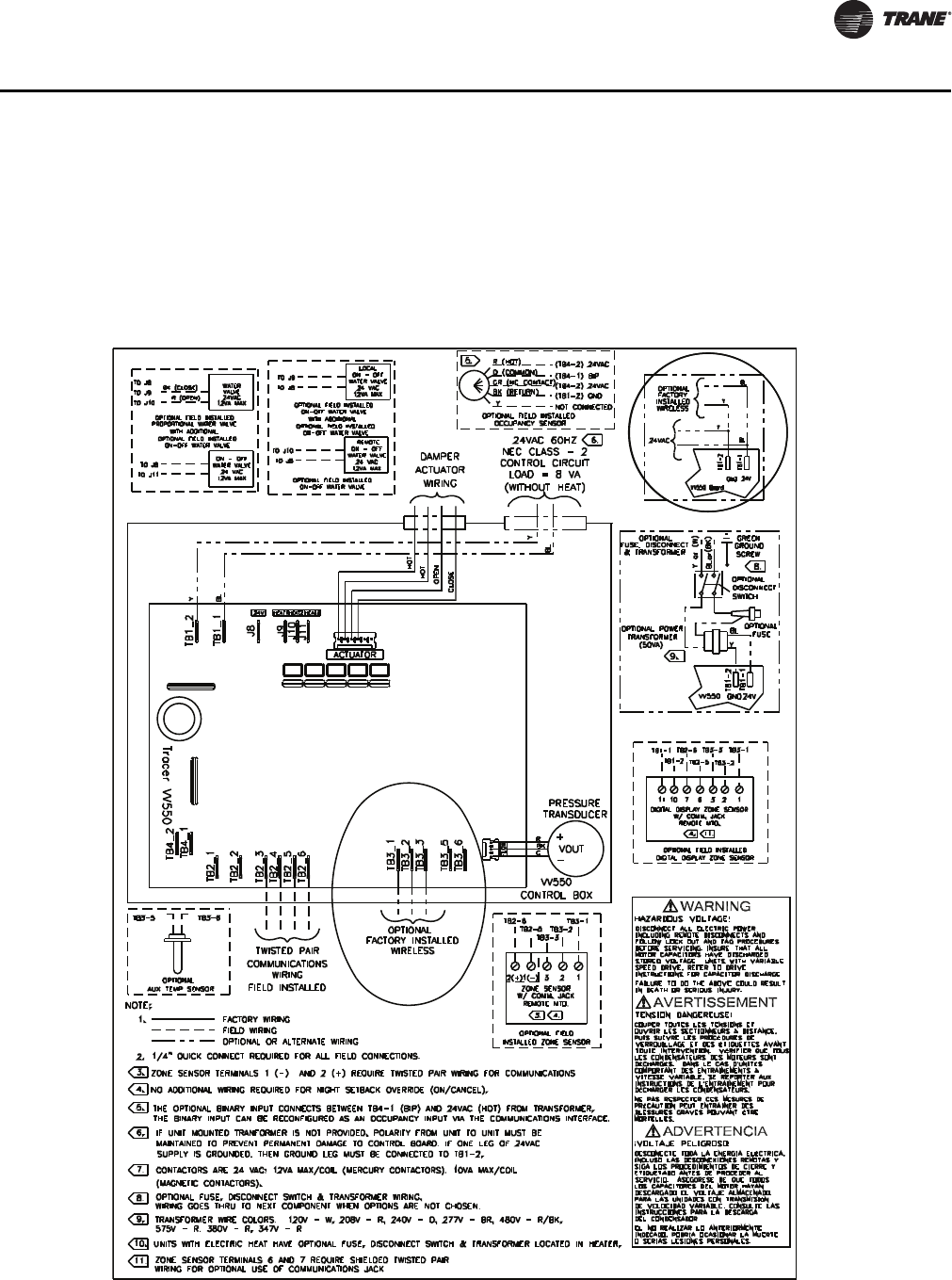
Wiring Diagram
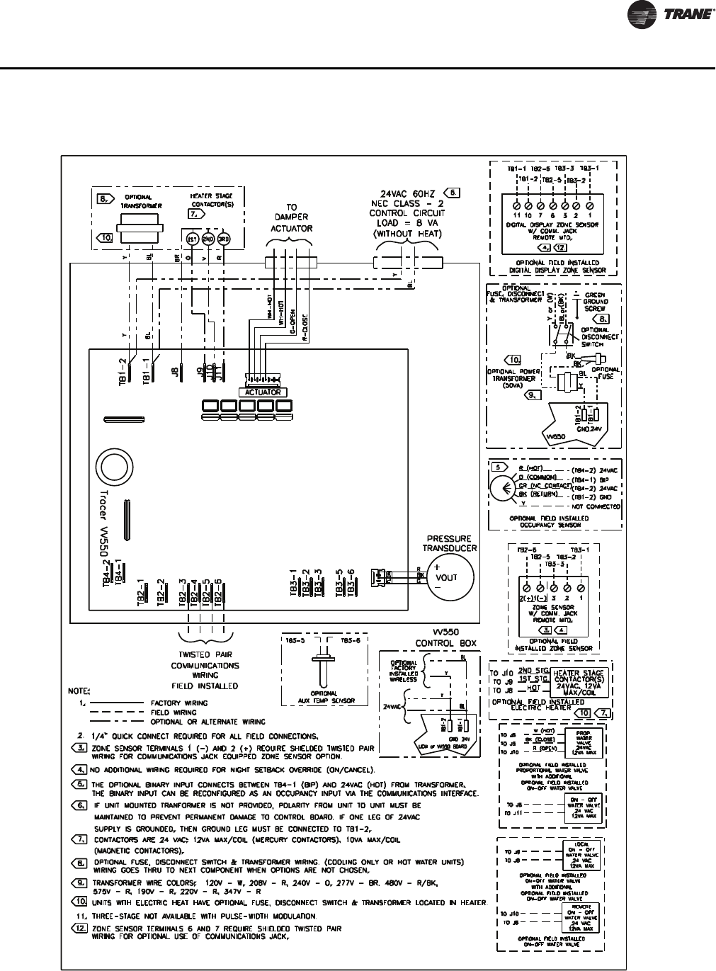
Figure 2, p. 17 shows a typical wiring diagram for the redesigned VAV VV550 hardware. The new
service part number is BRD2960.
VAV-SVP01A-EN 11
General Information
Shipping & Storage
Each VAV product and its service literature are shipped in the same package. When unpacking,
make sure that the literature is not lost or discarded with the packing material. Visually inspect the
individual components for obvious defects or damage. All components are thoroughly inspected
before leaving the factory. Any claims for damage incurred during shipment must be filed with the
carrier.
When any component of the VAV system and/or field installed accessories must be stored for a
period of time prior to being installed, they must be protected from the elements. The storage
location temperature should be between -40° to 150°F (-40° to 65.6°C) and the relative humidity
should be 10% to 90%, non-condensing. The warranty will not cover damage to the VAV system or
controls due to negligence during storage. A controlled indoor environment must be used for
storage.
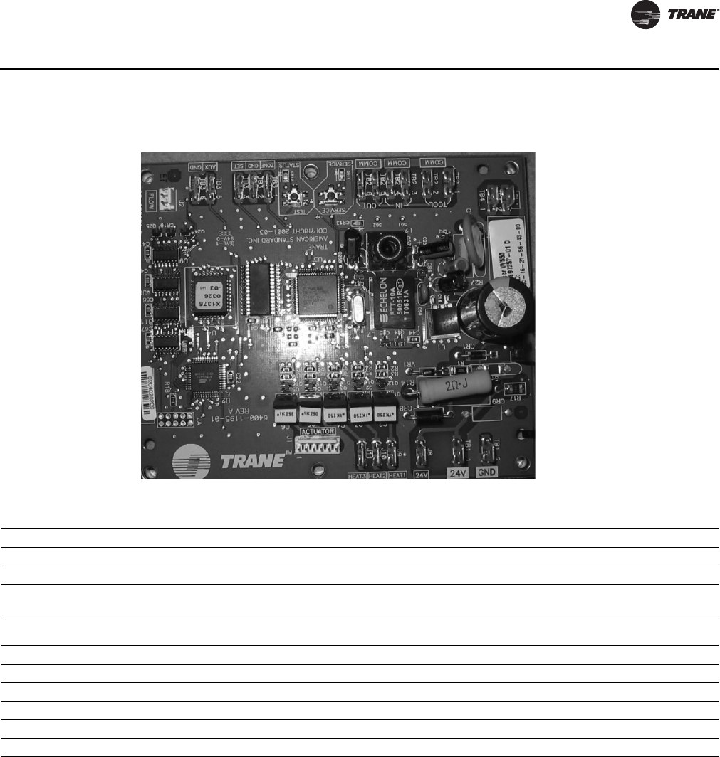
Figure 1. VV550 board layout
VAV VV550 controller and VAV 4.2 controller comparisons
VAV VV550 VAV 4.2
Supports Comm5 Supports only Comm4 or Comm3 (VariTrac or VariTrane)
No local CO2 sensor input. Uses only a communicated value Local CO2 sensor input is available.
Single star (*) initiates cool minimum airflow override. Single star (*) initiates maximum flow override after pressing the ON
button. Override is held until you move the thumbwheel.
Double star (**) initiates cool maximum airflow override. Double star (**) initiates unoccupied override after pressing the ON
button. Override is held until you move the thumbwheel.
Does not support VariTrac central control panel (CCP2 and CCP3). Does not support VariTrac CCP2 and CCP3.
Supports ventilation flow control Does not support ventilation flow control.
Supports flow tracking control. Does not support flow tracking control.
Supports enhanced ventilation control sequences. Does not support enhanced ventilation control sequence.
Supports auto-commissioning sequence. Does not support auto-commissioning sequence.
Supports zone sensor air balance sequences. Does not support zone sensor air balance sequence.
12 VAV-SVP01A-EN
General Information
Data Lists
If you’re going to connect to a generic building automation system, use Table 1, p. 12 and Tab le 2,
p. 13 for your points list.
Table 1. Input/output listing
Input Description Input SNVT type Output description Output SNVT type
Space temperature nviSpaceTemp SNVT_temp_p Space temperature nvoSpaceTemp SNVT_temp_p
Setpoint nviSetpoint SNVT_temp_p Unit status, mode nvoUnitStatus SNVT_hvac_status
Occupancy, schedule nviOccSchedule SNVT_tod_event Effective setpoint nvoEffectSetpt SNVT_temp_p
Occupancy, manual
command nviOccManCmd SNVT_occupancy Effective occupancy nvoEffectOccup SNVT_occupancy
Occupancy sensor nviOccSensor SNVT_occupancy Heat cool mode nvoHeatCool SNVT_hvac_mode
Application mode nviApplicMode SNVT_hvac_mode Setpoint nvoSetpoint SNVT_temp_p
Heat/cool mode input nviHeatCool SNVT_hvac_mode Discharge air
temperature nvoDischAirTemp SNVT_temp_p
Fan speed command nviFanSpeedCmd SNVT_switch Terminal load nvoTerminalLoad SNVT_lev_percent
Auxiliary heat enable nviAuxHeatEnable SNVT_switch Space CO2nvoSpaceCO2 SNVT_ppm
Valve override nviValveOverride SNVT_hvac_overid Effective air flow
setpoint nvoEffectFlowSP SNVT_flow
Flow override nviFlowOverride SNVT_hvac_overid Air flow nvoAirFlow SNVT_flow
Emergency override nviEmergOverride SNVT_hvac_emerg File table address nvoFileDirectory(a) SNVT_address
Source temperature nviSourceTemp SNVT_temp_p Object status nvoStatus(a) SNVT_obj_status
Space CO2nviSpaceCO2SNVT_ppm Alarm message nvoAlarmMessage SNVT_str_asc
Clear alarms/
diagnostics nviRequest(a) SNVT_obj_request
Air flow setpoint input nviAirFlowSetpt SNVT_flow
Ventilation ratio limit nviVentRatioLim SNVT_lev_percent
Ventilation for the zone
input nviVentSetpt SNVT_flow
(a) Part of the node object.
VAV-SVP01A-EN 13
General Information
Table 2. Configuration properties
Configuration property
description Configuration property SNVT type SCPT reference
Send heartbeat nciSndHrtBt SNVT_time_sec SCPTmaxSendTime (49)
Occ temperature setpoints nciSetpoints SNVT_temp_setpt SCPTsetPnts (60)
Minimum send time nciMinOutTm SNVT_time_sec SCPTminSendTime (52)
Receive heartbeat nciRecHrtBt SNVT_time_sec SCPTmaxRcvTime (48)
Location label nciLocation SNVT_str_asc SCPTlocation (17)
Local bypass time nciBypassTime SNVT_time_min SCPTbypassTime (34)
Manual override time nciManualTime SNVT_time_min SCPTmanOverTime (35)
Space CO2 limit nciSpaceCO2Lim SNVT_ppm SCPTlimitCO2 (42)
Nominal air flow nciNomFlow SNVT_flow SCPTnomAirFlow (57)
Air flow measurement gain nciFlowGain SNVT_multiplier SCPTsensConstVAV (67)
Minimum air flow nciMinFlow SNVT_flow SCPTminFlow (54)
Maximum air flow nciMaxFlow SNVT_flow SCPTmaxFlow (51)
Minimum air flow for heat nciMinFlowHeat SNVT_flow SCPTminFlowHeat (55)
Maximum air flow for heat nciMaxFlowHeat SNVT_flow SCPTmaxFlowHeat (37)
Minimum flow for standby nciMinFlowStdby SNVT_flow SCPTminFlowStby (56)
Firmware major version nciDevMajVer(a) n/a SCPTdevMajVer (165)
Firmware minor version nciDevMinVer(a) n/a SCPTdevMinVer (166)
Flow offset for tracking applications nciFlowOffset SNVT_flow_f SCPToffsetFlow (265)
Local heating minimum air flow nciMinFlowUnitHt SNVT_flow SCPTminFlowUnitHeat (270)
(a) Part of the node object

14 VAV-SVP01A-EN
VAV Start Up/Check Out Procedure
Chapter Overview
This chapter contains information about the following:
• VV550 Pre-Power Check-Out
• Power Wiring Requirements
• Light Emitting Diode (LED) Operations
• Communication Wiring
• Space Temperature Controller Analog Inputs
•Zone Sensor Wiring
•Auxiliary Sensor Wiring
•Binary Input Wiring
•Binary Output Wiring
• Ventilation Flow Control
•Auxiliary Sensor Wiring
• Flow Tracking Control
• Wireless Zone Sensor
VV550 Pre-Power Check-Out
WARNING
Live Electrical Components!
During installation, testing, servicing and troubleshooting of this product, it may be necessary to
work with live electrical components. Have a qualified licensed electrician or other individual who
has been properly trained in handling live electrical components perform these tasks. Failure to
follow all electrical safety precautions when exposed to live electrical components could result in
death or serious injury.
• Check the supply voltage at TB1. Proper polarity must be maintained. TB1-1 is the hot side (+)
and TB1-2 is the ground side (-) of the 24VAC input. Refer to Figure 2, p. 17 and Figure 3, p. 18
for the VAV VV550 Controller terminal locations. The VAV VV550 Controller cannot be powered
from a common 24VAC transformer that is supplying power to a device containing a full-wave
rectifier bridge in its power supply. The acceptable voltage is 18 to 32 VAC (24VAC cataloged).
However, voltages at either extreme may result in increased system instability.
• Verify that communications wiring has properly been terminated at TB2-1 (+) and TB2-2 (-).
Polarity is not important on the communications link.
• Verify that the zone sensor connections are correct as detailed in this IOP.
• If heat has been added to unit, verify that the proper output connections have been made as
detailed in this IOP.
• Verify that the tubing is properly connected to the transducer.
VAV-SVP01A-EN 15
VAV Start Up/Check Out Procedure
VV550 Power Wiring
Power Requirements
WARNING
Hazardous Voltage!
Disconnect all electric power, including remote disconnects before servicing. Follow proper
lockout/tagout procedures to ensure the power can not be inadvertently energized. Failure to
disconnect power before servicing could result in death or serious injury.
WARNING
Electrocution and Fire Hazards with Improperly Installed and Grounded
Field Wiring!
Improperly installed and grounded field wiring poses FIRE & ELECTROCUTION hazards. To avoid
these hazards, you MUST follow requirements for field wiring installation and grounding as
described in the National Electrical Codes (NEC) and your local/state electrical codes. All field
wiring MUST be performed by qualified personnel. Failure to follow these requirements could
result in death or serious injury.
Notice:
Use Copper Conductors Only!
Unit terminals are not designed to accept other types of conductors. Failure to use copper
conductors could result in equipment damage.
Use at least 16 AWG for power wiring and connect to terminal TB1-1 (+) and TB1-2 (-). 24VAC is
required to power the VAV VV550 Controller and has an acceptable voltage tolerance of 18 to 32
VAC. Refer to Figure 2, p. 17 and Figure 3, p. 18 for the VAV VV550 Controller terminal locations.
Replace the VAV VV550 Controller control box cover after field wiring to prevent any
electromagnetic interference.
Note: A dedicated 24VAC, 50VA NEC class 2 transformer is recommended to power the VAV VV550
Controller. When powering multiple VAV VV550 Controllers from one transformer, polarity
must be maintained. Terminal TB1-1 is designated positive (+) and terminal TB1-2 is
negative (-) to the unit casing ground
The power consumption for cooling only Series F Models (VariTrac and VariTrane) is 12 VA (4 VA
for the air valve/actuator and 8 VA for the VV550 control board). To determine the total VAV VV550
Controller power requirement, add the power consumption per stage to the circuit board power
requirement. For example, a Series F unit containing magnetic contactors with three stages of
reheat would consume 42 VA.
Table 3. VA for factory-installed components
Style Volt Amps
F - Style Actuator 4 VA
Air Valve Actuator C through E Style 12 VA
Varitrac Actuator 3 VA
Fan Power Fan Output 6 VA
Hot Water Proportional 4 VA
Hot Water 2 Position 6.5 VA
Electric Heater Magnetic Contactor 10 VA
Electric Heater Mercury Contactor 12 VA

16 VAV-SVP01A-EN
VAV Start Up/Check Out Procedure
Note: VariTrane and VariTrac cooling only Series D and E models consume 20 VA (12 VA for the
actuator and 8 VA for the board). The heating output ratings remain the same.
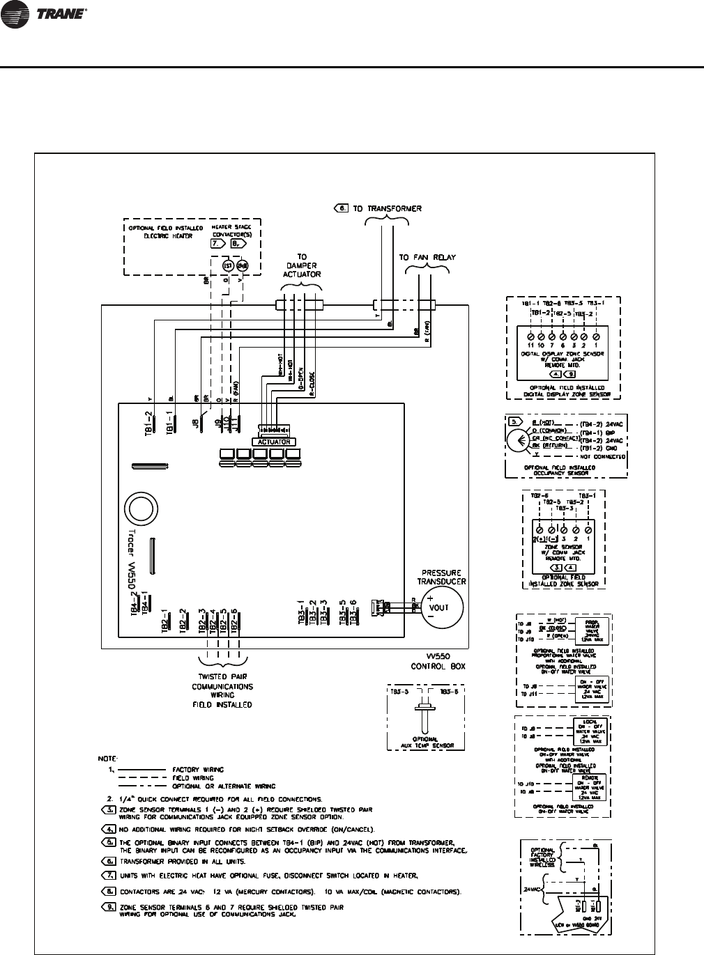
Refer to Figure 2, p. 17 and Figure 3, p. 18 for VAV VV550 Controller terminal locations and
Figure 59, p. 107 through Figure 66, p. 114 for wiring of output devices.
Light Emitting Diode (LED) Operations
Green Status LED
The green status LED is typically used to indicate whether or not the controller is powered On
(24VAC). This is the only LED under direct software control. The green status LED is Off when you
press the Test button. The green status LED blinks during manual output testing. Table 4, p. 16
shows and describes the green status LED activity.
Table 4. Green status LED activity
Green status LED activity Description
On Power On, normal operation
Off One of the following: Power Off Controller failure Test button pressed
Blinking for 10 seconds,
0.25 seconds Off; 0.25 seconds On Wink mode(a)
(a) The wink feature enables you to identify a controller. By sending a request from the Rover service tool, you can request
the controller to wink.
One blink continuously,
0.25 seconds Off; 2.25 seconds On
The controller is in the manual output test mode and no output-override unit
diagnostic2 conditions
Two blinks continuously,
0.25 seconds Off; 0.25 seconds On
0.25 seconds Off; 1.75 seconds On
The controller is in the manual output test mode and one or more output-
override unit diagnostic(b) conditions exist
(b) See the diagnostic topic in this guide for a complete list of output override diagnostics.
VAV-SVP01A-EN 17
VAV Start Up/Check Out Procedure
Figure 2. VV550 single duct control diagram
18 VAV-SVP01A-EN
VAV Start Up/Check Out Procedure
Figure 3. VV550 fan-powered control diagram

VAV-SVP01A-EN 19
VAV Start Up/Check Out Procedure
Communication Wiring
WARNING
Hazardous Voltage!
Disconnect all electric power, including remote disconnects before servicing. Follow proper
lockout/tagout procedures to ensure the power can not be inadvertently energized. Failure to
disconnect power before servicing could result in death or serious injury.
WARNING
Electrocution and Fire Hazards with Improperly Installed and Grounded
Field Wiring!
Improperly installed and grounded field wiring poses FIRE & ELECTROCUTION hazards. To avoid
these hazards, you MUST follow requirements for field wiring installation and grounding as
described in the National Electrical Codes (NEC) and your local/state electrical codes. All field
wiring MUST be performed by qualified personnel.
Failure to follow these requirements could result in death or serious injury.
Communication Link Wiring
• Use 22 AWG Level 4 unshielded communication wire for most Comm5 installations.
• Limit Comm5 links to 4,500 ft and 60 devices maximum (without a repeater).
• Use the following termination resistors on all links:
•105
Ω at each end for Level 4 wire
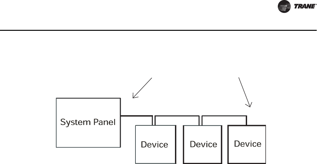
• Use daisy chain topology.
• Limit zone sensor communication stubs to 8 per link, 50 ft each maximum.
• Use one repeater for an additional 4,500 ft, 60 devices, and 8 communication stubs.
Recommended Wiring Practices
To ensure proper network communication, follow these recommended wiring and planning
guidelines when installing communication wire:
• All wiring must comply with the National Electrical Code (NEC) and local codes.
• Although Comm5 does not require polarity sensitivity, Trane recommends keeping polarity
consistent throughout the site.
• Make sure that 24VAC power supplies are consistent in how they are grounded. Avoid sharing
24VAC between Comm5 controllers.
• Avoid over tightening cable ties and other forms of cable wraps. This can damage the wires
inside the cable.
• Do not run Comm5 cable alongside or in the same conduit as 24VAC power. This includes the
conductors running from triac-type inputs.
• In open plenums, avoid running wire near lighting ballasts, especially those using 277 Vac.
• Use a daisy chain configuration.
• Use termination resistors as described in "Termination resistance placement for Comm5 links"
• Insulate termination-resistor leads.
• Use only one type of communication wire; do not mix different types
20 VAV-SVP01A-EN
VAV Start Up/Check Out Procedure
Wiring requirements
The recommended Comm5 communication-link wiring is 22 AWG, Level 4, twisted-pair wire. See
Ta ble 5, p . 2 0 "Specifications for Level 4-compliant cables". The wire can be either shielded or
unshielded. However, unshielded wire is recommended for most installations.
The maximum wire length for Comm5 communication links is 4,500 ft (1,400 m). Comm5
communication-link wiring must be installed in a daisy-chain configuration (Figure 4, p. 21 and
Figure 5, p. 22).
Table 5. Cable specifications
Specification Value
dc resistance
(Maximum resistance of a single copper conductor regardless of whether or not it is solid or stranded and regardless
of whether or not it is metal coated.)
18.0 Ω/1,000 ft 20°C
dc resistance unbalance (maximum) 5%
Mutual capacitance of a pair (maximum) 17 pF/foot
Pair-to-ground unbalance (maximum) 1,000 pF/foot/1,000 ft
Characteristic impedence 772 kHz 102 Ω ± 15%
1.0 MHz 100 Ω ± 15%
4.0 MHz 100 Ω ± 15%
8.0 MHz 100 Ω ± 15%
10.0 MHz 100 Ω ± 15%
16.0 MHz 100 Ω ± 15%
20.0 MHz 100 Ω ± 15%
Attenuation (maximum dB/1,000 ft at 20°C) 772 kHz 4.5 dB/1,000 ft at 20°C
1.0 MHz 5.5 dB/1,000 ft at 20°C
4.0 MHz 11.0 dB/1,000 ft at 20°C
8.0 MHz 15.0 dB/1,000 ft at 20°C
10.0 MHz 17.0 dB/1,000 ft at 20°C
Worst-pair near-end crosstalk (minimum)
(Values shown are for information only. The minimum NEXT coupling loss for any pair combination at
room temperature is to be greater than the value determined using the formula NEXT (FMHz)>NEXT
(0.772)-15log10 (FMHz/0.72) for all frequencies in the range of 0.772 MHz-20 MHz for a length of 1,000
ft.)
772 kHz 58 dB
1.0 MHz 56 dB
4.0 MHz 47 dB
8.0 MHz 42 dB
10.0 MHz 41 dB
16.0 MHz 38 dB
20.0 MHz 36 dB
dc resistance unbalance (maximum) 5%
VAV-SVP01A-EN 21
VAV Start Up/Check Out Procedure
Note: Use 105 Ω, 1%, 1/4 W for 22 AWG, Level 4.
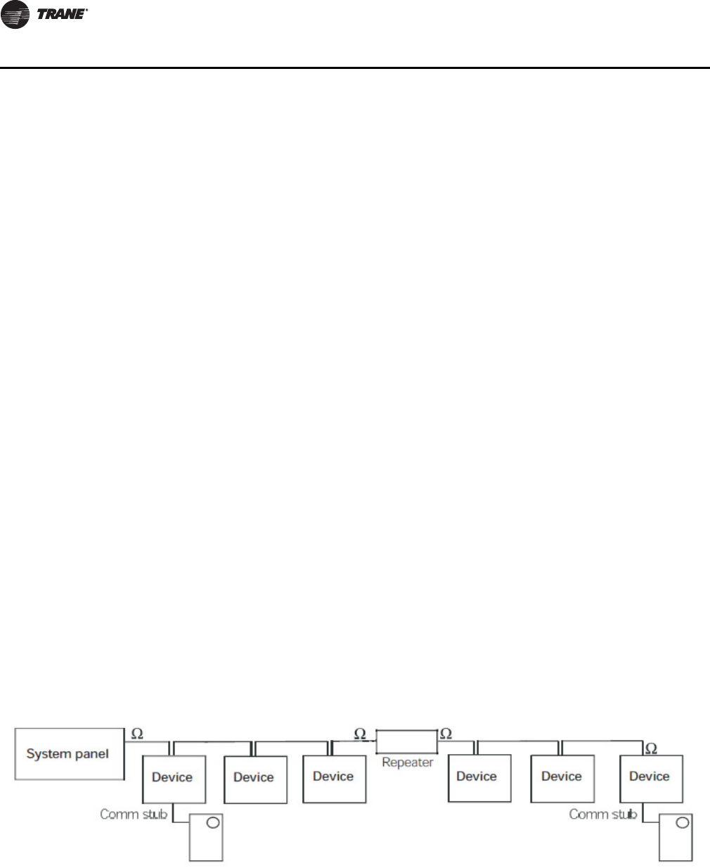
Comm5 Link Repeater
A Comm5 link repeater regenerates the signal on a Comm5 link. The configurations on either side
of the repeater should be daisy chain. Both link segments require proper termination (Figure 5,
p. 22).
Link repeater requirements.
A link repeater is required when:
• The total wire length is greater than the maximum wire run length of 4,500 ft (1,400 m).
• More than 60 devices are connected to a link-This total does not include the BCU, the link
repeater, and the temporary use of a service tool on the same link.
• More than eight zone sensor communication stubs (maximum 50 ft) are required on a Comm5
link
Link repeater connections.
The recommended shield connections are shown in Figure 6, p. 22. Use these connections for
instances where shielded communication wire is used. For an example of using a repeater to create
an extended daisy chain configuration, see Figure 5, p. 22.
Follow these guidelines when using a repeater:
• Read the Comm5 repeater installation (3270 3285) information that comes with the link
repeater.
• For information about terminating daisy chain configurations, see "Termination resistance
placement for Comm5 links" onFigure 4, p. 21.
• Connect shield-drain wires entering the repeater to a terminal marked with a capacitor symbol.
The entering shield-drain wire must be connected to earth ground at the system panel.
• Connect shield-drain wires leaving the repeater to the repeater terminal marked with an earth
ground symbol.
Figure 4. Daisy chain configuration
Ω
Ω
Termination Resistor

22 VAV-SVP01A-EN
VAV Start Up/Check Out Procedure
Notes:
1. Maximum wire length for the entire configuration is 4,500 ft (1,400 m).
2. Comm5 wire length limitations can be extended through the use of a link repeater, see “Comm5 physical link repeater.”
Figure 5. Alternate daisy chain configuration
Ω
ΩΩ
Ω
Termination
Resistors
Termination
Resistors
Figure 6. Comm5 shield repeater connection
VAV-SVP01A-EN 23
VAV Start Up/Check Out Procedure
Yellow Comm LED
The yellow Comm5 LED blinks whenever another controller is transmitting. However, the yellow
Comm5 LED does not blink when the controller is transmitting data. The yellow Comm5 LED cannot
distinguish between messages meant for the controller and messages that the controller ignores.
Ta ble 6, p . 2 3 shows and describes the yellow Comm LED activity.
Service Push Button
Important: If the Service button is held down for more than 15 seconds, the controller will
uninstall itself from the Comm5 network. The red service LED flashing
approximately once two every seconds indicates this mode (see Red service LED
above). Use the Rover service tool to restore the unit to normal operation. Refer the
Rover product literature for more information.
The Service push button can be used, as one of several methods, to install the controller in a
communication network. Refer to the Rover service tool product literature EMTX-SVX01*-EN for
more information.
Space temperature controller Analog Inputs
Zone Sensor Hardwired Option. Depending on the zone sensor options used, a maximum of
five wires may be required to run from the VAV VV550 Controller to the zone sensor. The zone
sensor options are:
• Zone sensor only (2 wires) - Part Number X13511528010.
• Sensor with night set back- Part Number X13511530010.
• Zone sensor with external adjustable - Part Number X13511529010.
• Zone sensor with external adjustable night set back, timed override (TOV) on/cancel button -
Part Number X13511527010.
• Digital zone sensor - Part Number X13511530010
• Communications jack - Part Number X13651467020 (for one box of 12)
Note: All wiring from the zone sensor to the Com link must be twisted shielded pair wiring.
Table 6. Yellow comm LED activity
Yellow Comm LED activity Description
LED Off continuously The controller is not detecting communication. (Normal for stand-alone applications.)
LED blinks or flickers The controller detects communication. (Normal for communicating applications, including data sharing.)
LED On continuously Abnormal condition or extremely high traffic on the link.
Table 7. Red service LED activity
Red service LED activity Description
LED is Off continuously after power is applied to the controller. Normal operation
LED is On continuously, even when power is first applied to the
controller. Someone is pressing the Service push button or the controller failed.
LED flashes about once every two seconds. Uninstalled (normal controller mode). Use the Rover service tool to restore
the unit to normal operation. Refer to the Rover product literature for more
information.
24 VAV-SVP01A-EN
VAV Start Up/Check Out Procedure
Zone Sensor Wireless Option (Wireless Zone Sensor). Receiver is used to receive a signal
from the wireless zone sensor and can be factory installed- Part Number X13790855010. The wiring
harness connects the receiver to the VAV VV550 Controller - Part Number X19051672010.
Zone Sensor Wireless Option (Zone Sensor). The wireless zone sensor with night setback
timed override (TOV) on/cancel button. Also can be ordered for Celsius and Fahrenheit setpoint
adjustment - Part Number X13790492010 (F), Digital Display wireless zone sensor- Part Number
X13790822010
Zone Sensor Wiring
Location and Mounting. A zone sensor in each control zone should be located in the most
critical area of the zone. Sensors should not be mounted in direct sunlight or in the area's supply
air stream. Subdivision of the zone may be necessary for adequate control and comfort. Avoid
mounting zone sensors in areas subject to the following:
• Drafts or "dead spots" behind doors or corners.
• Hot or cold air ducts.
• Radiant heat from the sun or appliances.
• Concealed pipes or chimneys.
• Unheated or uncooled surfaces behind the sensor such as outside walls.
• Air flows from adjacent zones or other units.
Wiring. Each unit must be controlled by a zone sensor that is designated specifically for use with
the VAV VV550 Controller. Field wiring for the zone sensors must meet the following requirements:
• Must be 14 to 18 AWG.
•Refer to Figure 2, p. 17 and Figure 3, p. 18 and the sensor instructions for terminal connections.
• If local codes require enclosed conductors, the zone sensor wires should be installed in conduit.
Do not route zone sensor wires in conduit with 24VAC or other high power conducting wires.
Zone sensor comm stubs. For the most reliable communications, limit the number of zone
sensor communication stubs to 8 per Comm5 link unless using a repeater then it is 16 stubs. Each
stub should not exceed 50 feet. Exceeding these limits increases the likelihood of communication
problems. Connect Communication wire to terminals TB2-5 and TB2-6 on VV550 controller and to
comm. Jack in zone sensor
Notes:
1. Maximum wire length on either side of the repeater is 4,500 ft (1,400 m).
2. The link repeater is limited to 60 devices on either side of the link.
3. Place termination resistors at the end of the link. Use a 105 X resistor at each end of the link for Level 4 wire
Figure 7. Communication stubs used with a repeater
VAV-SVP01A-EN 25
VAV Start Up/Check Out Procedure
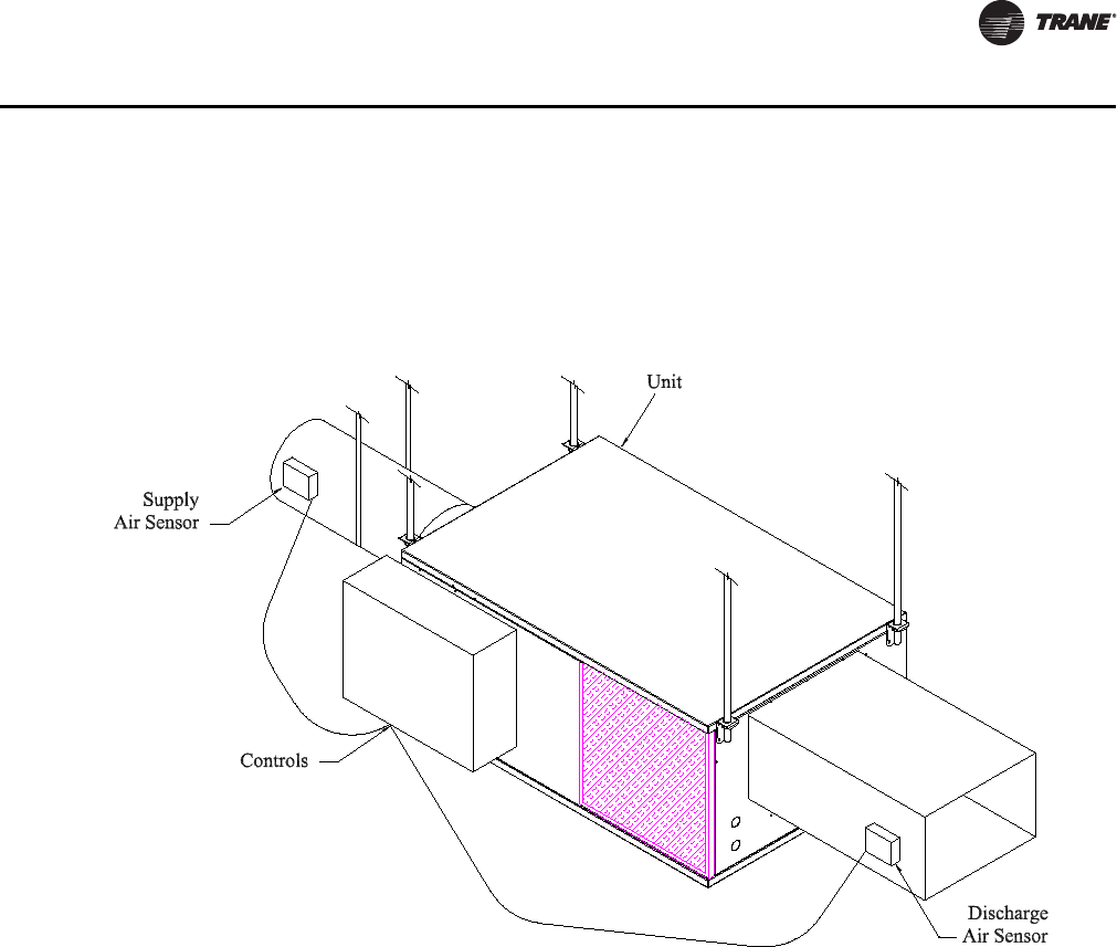
Auxiliary Duct Temperature Sensor
The typical mounting position of the auxiliary sensor is upstream of the VAV unit and connected
into the DDC controller at TB3-5 and TB3-6. Comm5 could be mounted downstream of the reheat
for improved diagnostics (Figure 8, p. 25). Refer to Controller Diagrams Figure 2, p. 17 and
Figure 3, p. 18 for the VAV VV550 Controller terminal locations.
Binary Input Wiring
Each VAV VV550 Controller provides one binary input. On the VV550 factory-installed controller, the
binary input configuration is set up at the factory. The binary input can be configured with Rover
service tool as occupancy or generic or not used. The input associates 0 Vac with open contacts and
24VAC with closed contacts. It is activated by a dry contact switch closure.
• Must be 14 to 18 AWG.
•Refer to Figure 2, p. 17 and Figure 3, p. 18 and the sensor instructions for terminal connections.
Occupancy Binary Input. The occupancy binary input can be configured as NO or NC. Occupied
is the normal state. It is also the initial state at power-up and after a reset. Unoccupied is the other
state. If the binary input is configured as generic, the default occupancy mode is occupied.
Generic Binary Input. The generic binary input can be configured as NO or NC. Normal state is
inactive and is also the initial state at power-up and after a reset. Active is the other state.
Not Used Input. When no device is connected to the input, configure the controller input as not
used.
Binary Outputs Wiring
Binary outputs that are required for unit operation are factory wired and commissioned.
Figure 8. Duct temperature sensors: upstream/downstream

26 VAV-SVP01A-EN
VAV Start Up/Check Out Procedure
Ventilation Flow control
See Auxiliary Duct Temperature Sensor wiring on Space temperature controller Analog Inputs
Note: If heat is installed Auxilary sensor will be located at the discharge of the VAV unit.
Flow Tracking Control
Two controls are used in Flow tracking controller. One is configured with the Space temperature
control program and the other controller will be set up as flow tracking controller and it will not
need any input or output device connected to the controller. See Operation section for details.
VAV-SVP01A-EN 27
VAV Start Up/Check Out Procedure
Wireless Zone Sensor
Overview
The Trane Wireless Zone Sensor set includes a sensor and a receiver that work together to provide
the same functions as the equivalent Trane wired sensor, such as the standard 10 k temperature
input (with the exception of the communication jack). No further software or hardware is necessary
for site evaluation, installation, or maintenance.
The sensor transmits the zone temperature, all zone temperature setpoint functions, timed override
Occupied (On) and timed override Unoccupied (Cancel) information to the receiver. The receiver
electrically reproduces the zone temperature resistance, all zone temperature setpoint function
resistances, and timed override On and timed override Cancel information as sent by the sensor.
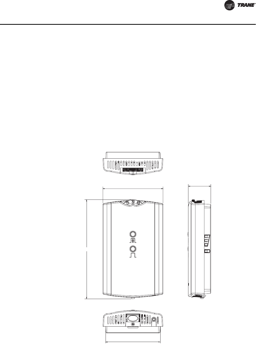
Dimensional Diagrams
See Figure 9, p. 27 and Figure 10, p. 28 for dimensions of the Wireless Zone Sensor set. The
dimensions are the same for both the sensor and the receiver.
Figure 9. Outside dimensions for sensor
2.90 in (7.35 cm)
1.08 in (2.75 cm)
4.78 in (12.14 cm)
2.62 in (6.65 cm)
Note: The dimensions are the
same for both the sensor
and the receiver.
28 VAV-SVP01A-EN
VAV Start Up/Check Out Procedure
Setting the Address, Mounting, Wiring, and Associating the Receiver and Sensor
The following procedure list shows the recommended order for installation:
• Choosing a Location for Mounting the Sensor.
• Setting the Rotary Address Switches on the Receiver and on the Sensor.
• Replacing and Securing the Receiver Cover.
• Powering the Sensor and Associating the Sensor to the Receiver.
• Applying Power to the Receiver.
• Testing Signal and Battery Strength.
• Disassociation.
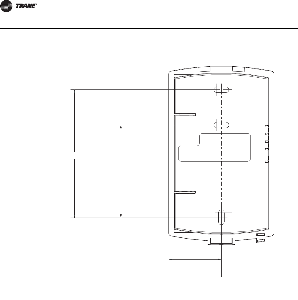
Figure 10. Mounting hole dimensions for sensor
3.27 in (8.30 cm)
2.36 in (6.00 cm)
1.34 in (3.41 cm)
Note: The dimensions are the
same for both the sensor
and the receiver.

VAV-SVP01A-EN 29
VAV Start Up/Check Out Procedure
Choosing a Location for Mounting the Sensor
Placement of the receiver and the sensor set is critical to proper operation. In most installations,
distance is not the limiting factor for proper radio signal quality. It is more greatly affected by walls,
barriers, and general clutter. For best radio transmission range and reliability, wherever possible,
mount the receiver and sensor in line of sight. Try to minimize the number of barriers between the
pair of devices. In general, sheetrock walls and ceiling tiles offer little restriction to the propagation
of the radio signal throughout the building; concrete or metal barriers offer the most restriction.
The transmission range for the sensor is as follows:
• Open range: 2,500 ft (762 m) (packet error rate = 2%)
• Usable range: 200 ft (61 m)
• Typical range: 75 ft (23 m)
Ambient considerations
Avoid locations that are outside the operating temperature and humidity range.
Location Considerations for the Sensor
When selecting a location for the sensor, consider both thermal and radio transmission
characteristics of the location.
Thermal considerations
• Avoid areas of direct sunlight.
• Avoid areas in the direct air stream of air diffusers.
• Avoid exterior walls and other walls that have a temperature differential between their two
sides.
• Avoid areas close to sources of heat such as sunlight, appliances, or other equipment.
• Avoid drafty areas.
• Avoid dead spots behind doors, projection screens, or corners.
Radio transmission considerations
• Avoid metal barriers between the sensor and receiver, such as plastered walls with metal lathe.
They will decrease radio signal quality.
• Avoid placing the sensor inside metal enclosures.
• Avoid radio transmissions through thick, solid concrete walls.
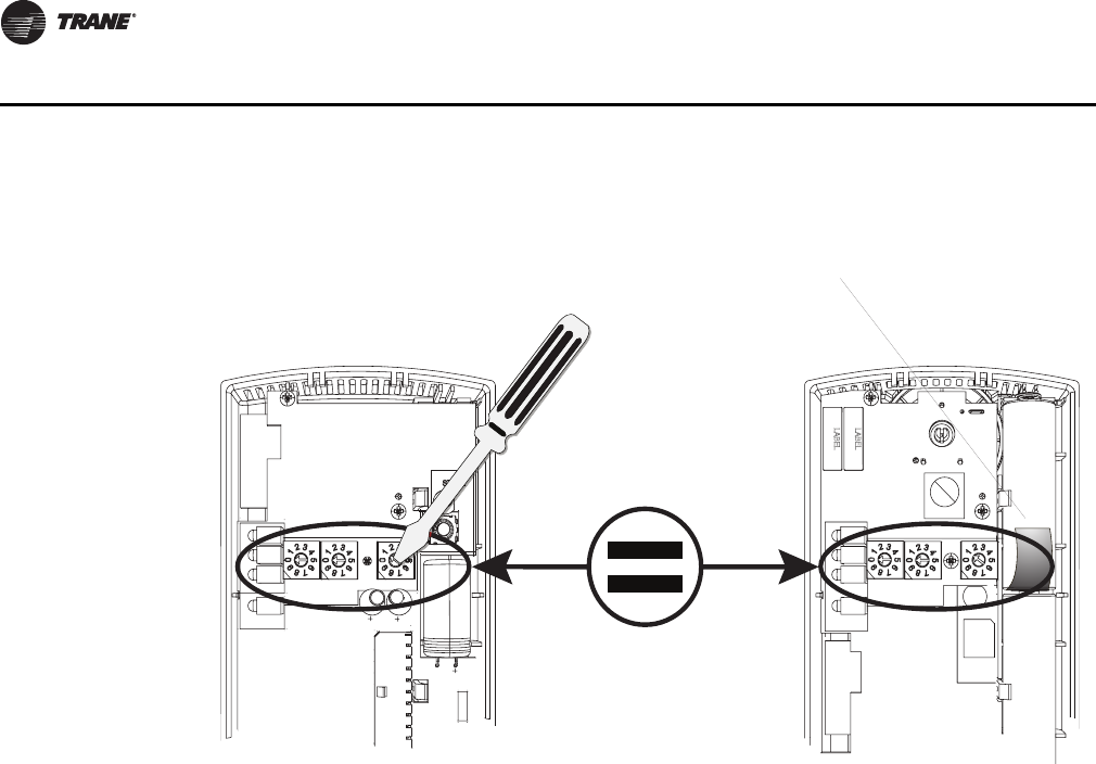
Setting the Rotary Address Switches on the Receiver and the Sensor
Note: To expedite the installation and association process, set the addresses before applying
power to the receiver.
The process of establishing communication between the receiver and sensor is referred to as
association. The receiver and the sensor must have their rotary switches set to the same address
in order to enable communication between the two devices (see Figure 11, p. 30). Important
limitations are as follows:
• Only one associated receiver/sensor set can communicate within the reception range of the
wireless system.
• It is not possible to associate more than one sensor to a receiver, nor is it possible to associate
more than one receiver to a sensor.
30 VAV-SVP01A-EN
VAV Start Up/Check Out Procedure
Setting the Receiver Address
1. Using a small screwdriver, set the three rotary address switches (locations S1, S2, S3) on the
receiver (Figure 11, p. 30) to an address between 001 and 999.
Note: Do not use 000 as an address for installation. If you set the receiver address to 000, it will:
– Return the receiver outputs to their factory defaults indefinitely (zone temperature and
setpoint outputs: 72.5°F [22.5°C]).
– Remove all association knowledge.
– Make the receiver unable to associate with a sensor.
•Read the switches from left to right in the order in which they are numbered (S1, S2, S3).
•Zero is at the nine o'clock position.
2. Make a notation of the address and location of the receiver.
Setting the Sensor Address
1. Using a small screwdriver, set the three rotary address switches (locations S1, S2, S3) on the
sensor (Figure 11, p. 30) to the same address used for the receiver it is to be associated with.
2. Make a notation of the address and location where this sensor is to be mounted.
Note: Do not use 000 as an address for installation. If you set the address to 000, it will:
– Remove all association knowledge.
– Revert to a low-power hibernation mode.
– Send a disassociation request to the receiver. If the sensor and receiver are associated and
communicating at the time the sensor is set to 000 and the Test button is pressed, the
receiver will also become unassociated and will be available for re-association.
• Read the switches from left to right in the order in which they are numbered (S1, S2, S3).
• Zero is at the 9 o'clock position.
Figure 11. Setting the rotary address switches on the receiver and the sensor
S5
GND
R77
C35
S1 S2
C33
LED4
S4
S5
S3
LED1
LED2
LED3
LED5
C34
J1
COMM -
24VAC/DC
SETPOINT
HEATING SET
SIGNAL
POWER
ADD
DRESS
FAN/SYSTEM
ZONE
COMM +
IN
STALL
WIRELESS
GND
!B1 +
INSTALL
WIRELESS
S4
S3
S2
S1
ADDRESS
STATUS
BATTERY
LED5
SIGNAL
LED3
LED2
LED1
Pb
Pb-FREE
STATUS
LED4
L
T
A
L
L
L
E
S
S
L
T
A
A
L
E
Do not remove the
insulation strip yet.
VAV-SVP01A-EN 31
VAV Start Up/Check Out Procedure
3. Make a notation of the address and location of the sensor.
Factory Wiring of the Receiver to the VAV Unit Controller
The required power for the receiver is 24VAC or 24 Vdc and is less than 1 VA. The receiver is
designed to be powered by the VAV VV550 Controller. See Figure 12, p. 31.
Note: A dedicated transformer is not necessary or advised.
Figure 12. Factory wiring of the receiver to the VAV VV550 controller
32 VAV-SVP01A-EN
VAV Start Up/Check Out Procedure
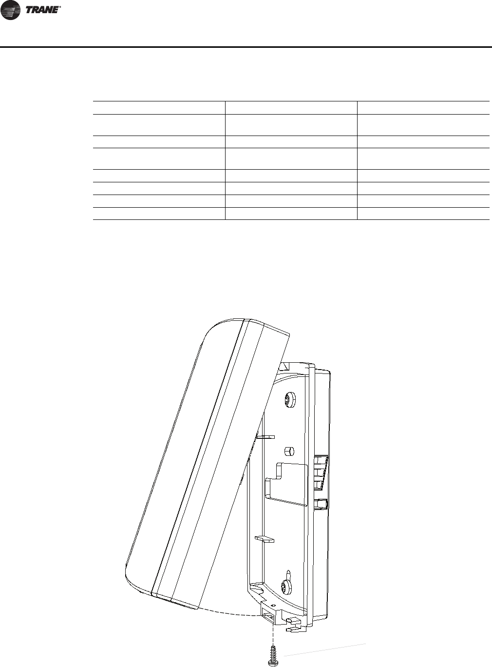
Replacing and Securing the Receiver Cover
1. To replace the receiver cover on the base plate, hook the cover over the top of the base plate.
Apply light pressure to the bottom of the cover until it snaps in place.
2. If necessary to keep the cover securely attached, install the security screw into the bottom of
the receiver (Figure 13, p. 32).
Table 8. Wiring harness: wire identification
Wire Label Color Function
HEATING SET Brown Space temperature heating setpoint
(WDS only)
FAN SYSTEM Green Fan and system control (WDS only)
SETPOINT Red Space temperature setpoint (WDS and
W2S only)
ZONE White Zone temperature
GND-SIGNAL Black Ground for setpoint and zone signal
24VAC/DC Blue 24VAC/vdc power
GND-POWER Yellow Ground for 24VAC/dc
Figure 13. Snap receiver cover on base plate and attach security screw
Security screw
VAV-SVP01A-EN 33
VAV Start Up/Check Out Procedure
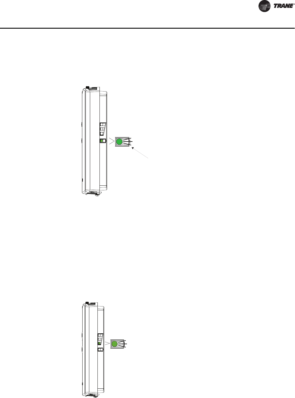
Applying Power to the Receiver
Restore power to the VAV VV550 Controller. Observe LED5 on the receiver (Figure 14, p. 33). It will
light and stay constantly On when 24 V power is normal.
Receiver Indicates Readiness to Associate
After initial power up, the receiver conducts a channel scan for 10 seconds. During this time, the
receiver selects from 16 available channels the clearest channel on which to operate. LED1, LED2,
and LED3 flash rapidly in succession (round-robin style) while the channel scan is in progress.
Note: Do not attempt association until the channel scan is finished. After the channel scan is
finished, LED3 will begin blinking (one-blink pattern) to show that the receiver is ready to
be associated with a sensor. LED3 will stop blinking when association has been established
(Figure 15, p. 33).
Figure 14. LED5 stays on after applying power to the receiver
Figure 15. LED3 blinks when the receiver is ready to be associated with a sensor
LED5 stays constantly On
RECEIVER
LED3
LED3 will begin
to blink after
10 seconds
34 VAV-SVP01A-EN
VAV Start Up/Check Out Procedure
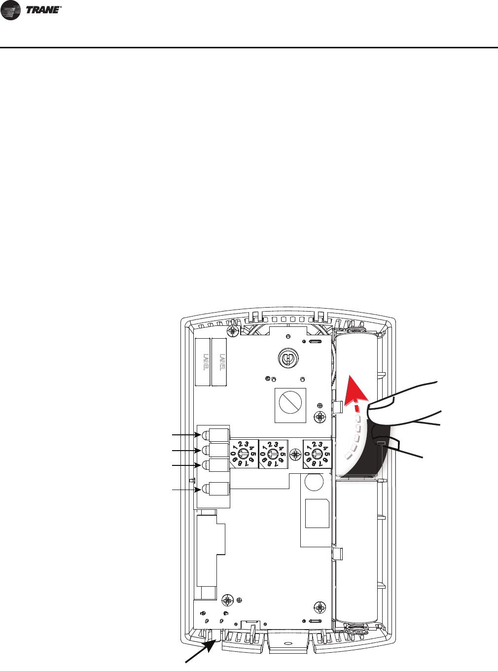
Powering the Sensor and Associating the Sensor to the Receiver
1. Verify that the sensor is set to the same address as the receiver it is to be associated with.
2. Remove the insulation barrier, which is a plastic strip located between the two batteries
(Figure 16, p. 34).
3. Association will automatically occur between the sensor and the receiver. If the first association
attempt is unsuccessful, the sensor will automatically reattempt association with the receiver
every 10 minutes.
Note: A disassociated sensor will transmit an association request every 10 minutes. An associated
sensor that has lost communication with the receiver will transmit an association request
every 50 minutes.
Note: LED3 on the receiver stops blinking to indicate that association has been established.
Figure 16. Removing the insulation barrier on the sensor
B1 +
B2 -
IINSTALL
WIRELESS
S4
S3
S2
S1
ADDRESS
STATUS
BATTERY
LED5
SIGNAL
J1
Pb
Pb-FREE
STATUS
LED4
LED5
LED1
LED2
LED3
S5
SENSOR
+
–
+
–

VAV-SVP01A-EN 35
VAV Start Up/Check Out Procedure
Testing Signal and Battery Strength
The following recommended test indicates signal and battery strength. It verifies that the
association process was successful and that the batteries have adequate charge. (For more
information on LEDs, see "Troubleshooting" chapter.)
1. Firmly press and release the Test button (S5) on the bottom of the sensor (Figure 17, p. 35).
2. View LED1, LED2, and LED3 to determine the strength of the signal. View LED5 to determine
the strength of the battery.
Note: The LEDs will turn Off after 5 seconds to conserve battery strength.
3. Record the results in your commissioning statement.
Disassociation
The receiver removes all stored association information, conducts a channel scan, and restarts
itself, if any of the following are true:
• The receiver address is changed from its current setting (001-999).
• The receiver receives a disassociation notification from its associated sensor.
• The receiver does not receive a communication from its associated sensor within 35 minutes.
Configuring the Wireless Sensor (Model Digital Display WDS only)
The configuration of the sensor determines which system features can be accessed and changes
can be made by the tenant (for example, changes to cooling/heating mode, setpoint, or fan speed.
Verify system and associated unit features before configuring the sensor.
Figure 17. Wireless sensors
LED1
LED2
LED3
LED5
srosnes SDW ledoMsrosnes SZW dna STW ledoM
Test bu t t on
Push firmly,
then release
Push firmly,
then release
Test bu t t on

36 VAV-SVP01A-EN
VAV Start Up/Check Out Procedure
The building owner or operator may choose to limit tenant access to certain features. This can be
done through configuration. Or, if a sensor is configured to match all control capabilities of the
building automation system, the locking feature can be used to restrict the tenant from making
changes.
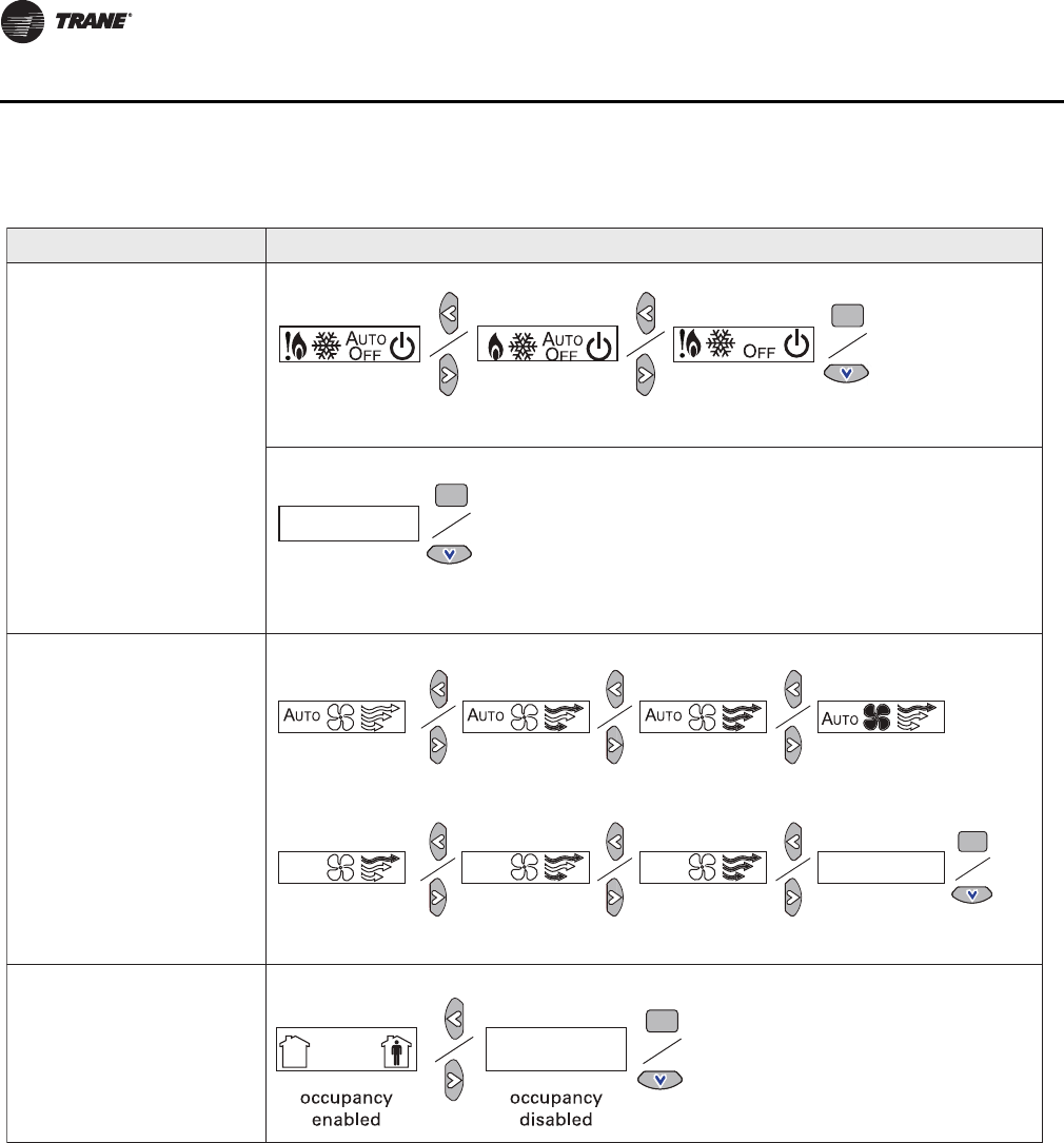
Configuration Procedure
To configure settings on the model WDS sensor, follow this procedure in the order presented.
1. Press the configuration button for 3 seconds.
The display will change to configuration mode. When the sensor is in configuration mode, a
wrench symbol appears on the display and the menus are separated by lines, as illustrated
below.
2. Press the center button on the keypad to begin the configuration process.
Figure 18. Configurations
Figure 19. Configuration mode
Configuration button
VAV-SVP01A-EN 37
VAV Start Up/Check Out Procedure
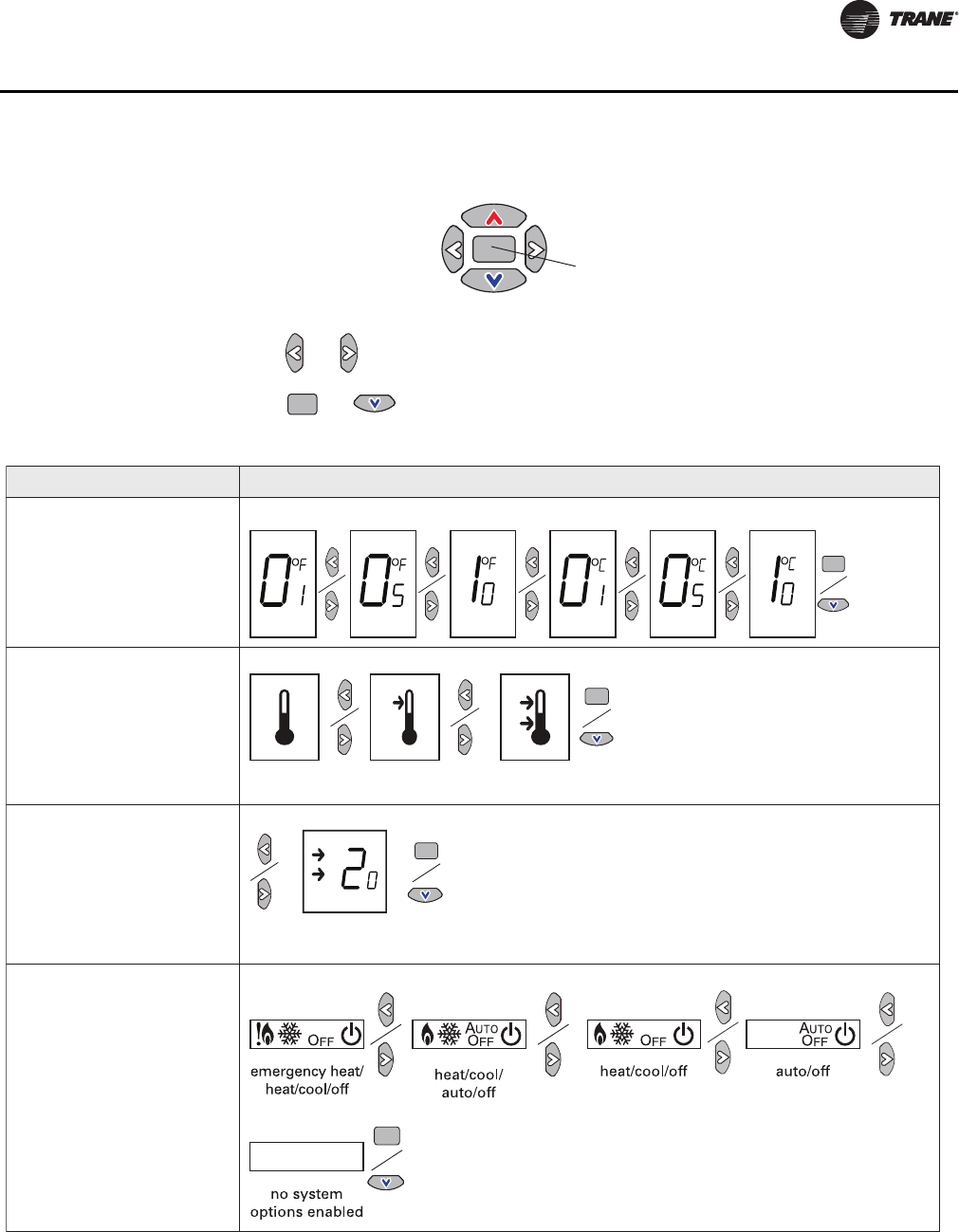
3. Configure the sensor options in the order shown in the table.
•Press or to scroll to the next selection.
•Press or to move to the next menu.
Figure 20. Center button
Center button
Figure 21. Wireless configuration
Setting Configuration options
Temperature
• Choose Fahrenheit or
Celsius
• Choose the degree
resolution (whole degrees,
half degrees, or tenths of
degrees).
Setpoint
Deadband (available for dual
setpoint system only)
Note: Deadband refers to the
minimum difference
between the heating and
cooling setpoints.
System
a) Single setpoint
. . .
.
.
.
dual setpoint
no
setpoint
single
setpoint
.
heat/cool setpoint offset
(1.8˚F – 10.8˚F, 1˚C – 6˚C)
38 VAV-SVP01A-EN
VAV Start Up/Check Out Procedure
System (continued)
b) Dual setpoint
c) No setpoint
Fan
Note: Fan control not available
on VAV units.
Occupancy (timed
override)
Setting Configuration options
emergency heat/
heat/cool/off
heat/cool/
auto/off
emergency heat/
heat/cool/auto/off
no system
options enabled
auto/off/low
med/high
auto/off/
low/high
auto/off
off/high (on) off/low/high off/low/
med/high
no fan options
enabled
auto/high (on)
VAV-SVP01A-EN 39
VAV Start Up/Check Out Procedure
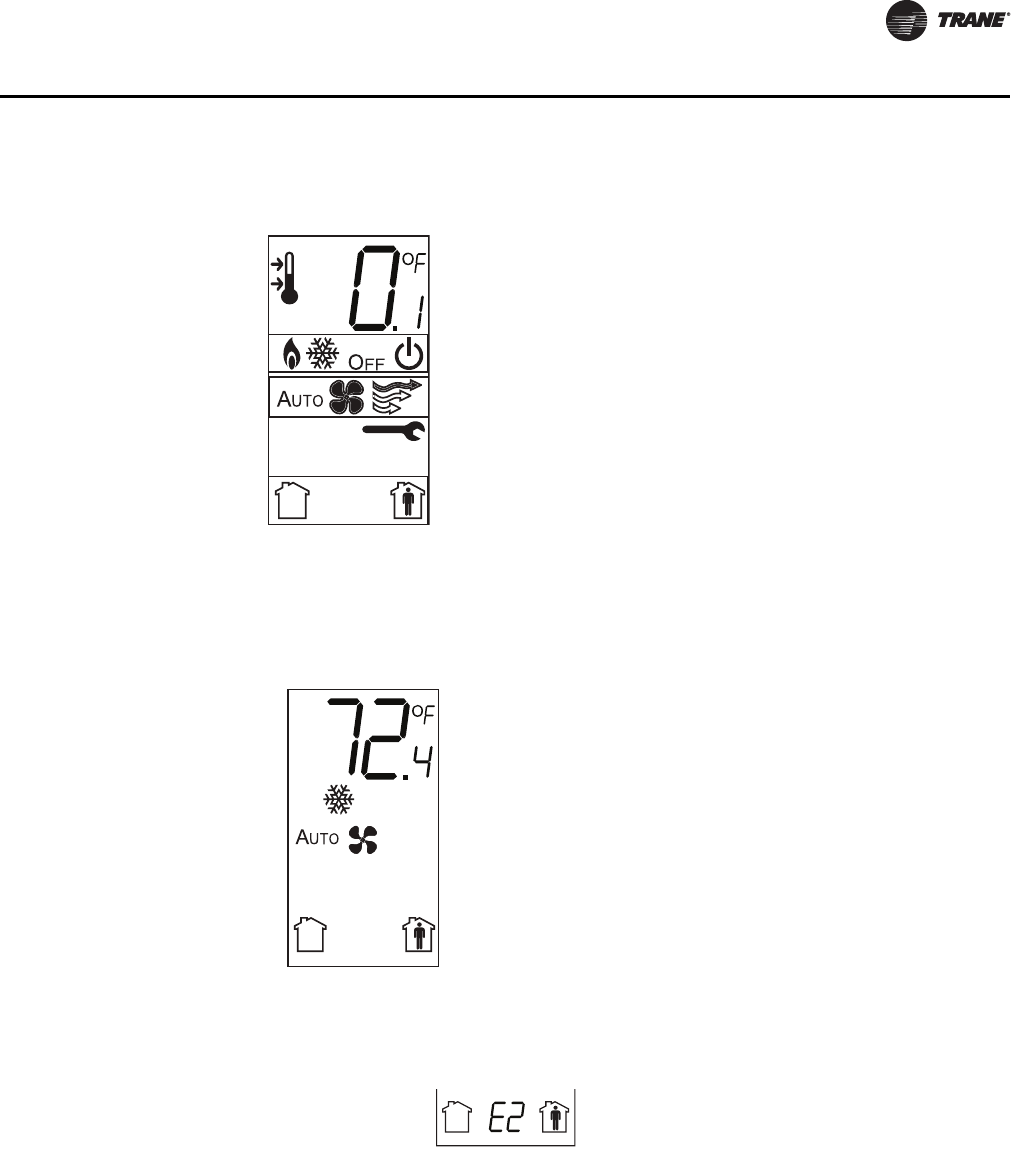
4. Review the display to ensure that you have selected the correct configuration options.
To return the display to operating mode, press the configuration button (See Step 1).
Note: The sensor will revert to operating mode if no buttons are pressed for 10 minutes.
The following example shows a configured display in operating mode.
If an error exists, it appears at the bottom of the display between the occupancy symbols, as shown
in below. SeeTable 20, p. 92 for error code definitions.
Figure 22. Configuration options
The example shows a display that has been configured for:
• Dual setpoint
• Temperature units (Fahrenheit)
• Temperature resolution to tenths of a degree
• System settings: Heat, Cool, Off
• Fan Settings: Auto and On
• Occupied/unoccupied option enabled
Figure 23. Display
Display shows the following:
• Temperature units (Fahrenheit)
• Temperature resolution to tenths of a degree
• System setting: Cooling
• Fan Setting: Auto
• Occupied/Unoccupied option enabled
Figure 24. Error message

40 VAV-SVP01A-EN
VAV Start Up/Check Out Procedure
Optional Features
Displaying Setpoint or Temperature
You can configure the sensor to display either the temperature (default) or setpoint. To select either
option:
1. Verify that the sensor is in operating mode and at the home screen.
2. Press the up and down arrows for 3 seconds. The arrow indicates setpoint display, as shown
in the illustration.
Locking and Unlocking Settings
You can lock or unlock the setpoint, system, or fan setting to prevent changes.
To lock or unlock the settings:
1. Verify that the sensor is in operating mode and at the home screen.
2. Choose a setting to lock or unlock.
•Select the setpoint by pressing the up or down arrow.
•Select the system menu by pressing the center button. Use the left or right arrow to choose
the setting.
•From the system menu, press the down arrow to select the fan menu. use the left or right
arrow to choose the setting.
Figure 25. Setpoint or temperature display
Figure 26. Setpoint
Figure 27. System menu
Arrow
indicates
setpoint is
shown on
display
Setpoint
System menu

VAV-SVP01A-EN 41
VAV Start Up/Check Out Procedure
Note: Fan on VAV units cannot be controlled from the zone sensor.
3. Press the left and right arrows for 4 seconds.
If you try to access a feature that is locked, the lock symbol will appear on the displays. If you press
a keypad button to try and change a locked setting, the locked symbol will flash.
Figure 28. Fan menu
Figure 29. Arrows
Fan menu
42 VAV-SVP01A-EN
VAV VV550 Controller Programming and Operation
Chapter Overview
This chapter contains information about the following:
• Accessing Rover/Comm5 LonTalk
• VV550 Controller Device Home Tabs: At a Glance
• Entering and Exiting the Service Mode
• Overriding VAVs
• Saving VAV Program
• VV550 Controller Device Home Tabs: Instructions
Accessing Rover/Comm5 LonTalk
Rover Overview
Rover is a service tool that allows parameters to be viewed or adjusted in the VAV VV550 Controller.
The operating and programming guide for Rover is EMTX-SVX01*-EN. Rover Comm5 is a software
application for monitoring, configuring, balancing, binding and testing VAV VV550 Controllers on
Comm 5 links.
Note: For Instructions on how to use Rover Comm5, refer to the Rover Comm5 online Help by
clicking Contents and Index on the Help menu.
Laptop Requirements and Complete Connection Instructions
For instructions on connecting a PC laptop to a Comm5 link, refer to the Installing Rover Service
Tool Version 5.0, 3270 3275.
Note: A hard copy of this document is in the Rover package and an electronic copy
(Installation.pdf) can be found on the Rover installation CD-ROM.
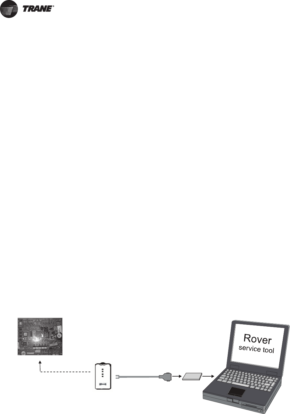
To connect to a Comm5 Link
1. Insert the Comm5 card in the PC laptop.
2. Connect the cables as shown in the appropriate figure. Refer toFigure 30, p. 42 for connecting
to a Comm5 controller through a zone sensor and Figure 31, p. 43 for Connecting to a Comm5
controller using alligator clips.
Note: Make sure to maintain polarity.
Figure 30. Connecting to a Comm5 controller through a zone sensor.
Adapter cable
RJ11
plug
Comm5
PCMCIA card
VAV-SVP01A-EN 43
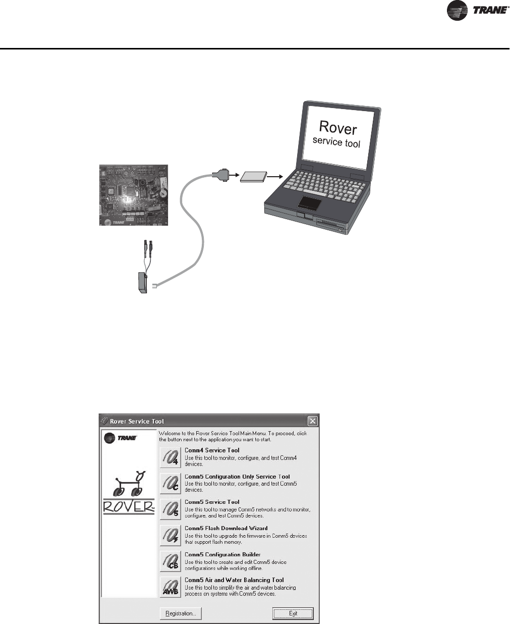
VAV VV550 Controller Programming and Operation
3. Double-click the Rover icon on the laptop PC desktop. The Rover Service Tool screen will
appear.
4. Double-click on the Comm5 Configuration Only Service Tool icon to access a Comm5
VV550. This tool allows the user to monitor, configure, and test Comm5 VV550 controller.
Note: The configuration-only Rover Comm5 software runs only in the Passive mode. This means
that you can configure setpoints and other controller parameters but cannot create bindings
or set up peer-to-peer Comm5 networks. All other Rover Comm5 features are available.
5. Rover Comm5 will launch and the Rover service tool will automatically Scan for Neron ID of
Devices.
6. Once the scan is complete, the results will populate the device tree on the left-hand side of the
Rover Comm5 screen.
7. Access the desired VAV VV550 Controller from the device tree.
Figure 31. Connecting to a Comm5 controller using alligator clips
Figure 32. Rover service tool
Comm5
PCMCIA card
Adapter
cable
RJ11 plug
Black
Red
44 VAV-SVP01A-EN
VAV VV550 Controller Programming and Operation
VV550 Controller Device Home Tabs: At a Glance
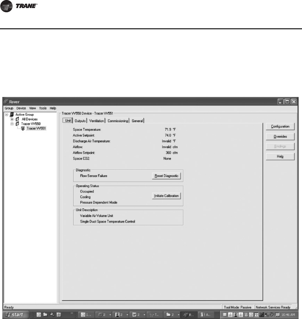
Unit Information Tab
Space Temp: The temperature, as reported by the zone sensor.
Active Setpoint: The active (or actual) setpoint currently used by the VAV VV550 Controller. Can
be either Heating or Cooling depending on operating mode.
Primary Air / Discharge Air Temperature: Shows the auxiliary temperature input.
Note: This will be defined in configuration as either Primary Air or Discharge air temperature
depending on unit control strategies. See Configuration section for more details.
Airflow: Measured in CFM. When a valid flow value is present, the controller operates under
pressure independent control. If after an airflow sensor failure, the airflow returns to the valid range
(airflow value greater than 10% of configured nominal airflow), the controller automatically
resumes pressure independent control. When the communicated airflow setpoint is invalid, the
flow sensor has failed, or calibration has failed, the controller closes the air valve if the configured
Figure 33. Unit tab

VAV-SVP01A-EN 45
VAV VV550 Controller Programming and Operation
airflow tracking offset is negative. If the configured airflow tracking offset is positive, the controller
opens the air valve to the configured maximum airflow space.Once a valid differential pressure is
established through the local hardwired input and then is no longer present, the controller
generates a flow sensor failure diagnostic.
Airflow Setpoint: The VV550 controllers support one modulating air valve for heating and
cooling operation. The controller positions the modulating air valve to deliver the desired airflow
(cooling or heating capacity). The desired airflow is called the active flow setpoint. The airflow
control algorithm compares the active airflow setpoint with the measured airflow and calculates
the necessary air valve movement to minimize error. The airflow setpoint is limited by applicable
minimum and maximum flow setpoints.
Space CO2: Communicated Value only. CO2-based demand control ventilation uses the
communicated space CO2 value. The controller cannot monitor CO2 from a local CO2 sensor. The
controller compares the space CO2 concentration to the configured band of CO2 values and
determines the demand ventilation rate of the zone. The resulting ventilation rate is called the
effective ventilation setpoint. The effective ventilation setpoint is the outdoor airflow required to
provide ventilation. It is used to calculate the ventilation ratio of the zone.
Diagnostic
This is a log that records each diagnostic independently of other diagnostics.
Note: A list of diagnostics will be located in troubleshooting section of this manual.
Use the ‘Reset Diagnostic’ button to reset the diagnostic from this point. A reset clears latching
diagnostics and enables the controller to try to run normally. If the latching condition is still present
after the reset, the controller shuts down. A reset resets a unit that is running normally. There are
five ways to reset unit diagnostics:
• Manual output test at the controller
• Cycling power to the controller
• BAS (communicated status request, clear alarm)
• Rover service tool (communicated status request, clear alarm)
• A communicating device able to access the controller diagnostic reset input (communicated
status request, clear alarm)
Operating Status
Occupancy Modes: There are four valid occupancy modes of the VAV VV550 Controller, and they
would be displayed at under operating status. The four occupancy modes are:
• Occupied mode
• Unoccupied mode
• Occupied standby mode
• Occupied bypass mode
Control Mode Field: This is were the controller will display the heating or cooling mode of the
controller. The controller can receive communicated requests for heating or cooling operation.
Field options are: Heating, Cooling, and Calibration.
Pressure Dependent (or Independent) Mode: This is were the controller will display if it has
a valid flow input to the controller from the flow ring and pressure transducer. The controller can
operate with or without a valid flow value (either hardwired or communicated). It operates under
pressure dependent control or pressure independent control.
Pressure dependent control - When a valid flow value is not present, the controller operates under
pressure dependent control (position control). Pressure dependent control substitutes the air valve
position for the flow measurement for all control actions.

46 VAV-SVP01A-EN
VAV VV550 Controller Programming and Operation
Pressure independent control - When a valid flow value is present, the controller operates under
pressure independent control. If after an airflow sensor failure, the airflow returns to the valid range
(airflow value greater than 10% of configured nominal airflow), the controller automatically
resumes pressure independent control.
Initiate Calibration button: The calibration sequence enables the controller to calibrate the air
valve position and the water valve position.
Unit Description
Describes the type of device being communicated to via Rover service tool. It also indicates the
general program that has been placed in controller.
Outputs Tab
Fan Status: The Fan will be shown as On, Off, or None.
Air Valve Position: Indicates air valve or damper position.
Reheat Capacity: Will indicate reheat capacity in Percentage.
Figure 34. Outputs tab

VAV-SVP01A-EN 47
VAV VV550 Controller Programming and Operation
Ventilation Tab
Note: For more information on this Ventilation Tab and how the VAV VV550 Controller interfaces
with Tracer Summit™, see CNT-SVX17*-EN
Ventilation Ratio: The Tracer Summit BAS uses the communicated ventilation ratio limit to tell
the controllers how much outdoor air is in the primary air. However, the air handler may not be able
to provide as much outdoor air as the system requires due, for example, to a low outdoor air
temperature. If the communicated ventilation ratio limit is not sufficient, the controller can raise its
minimum airflow setpoint as long as the space temperature remains under control.
Effective Ventilation Setpoint: The Tracer Summit BAS uses the effective ventilation setpoint
from all the VAV boxes to calculate how much outdoor air (OA) the system needs.
Active Minimum Airflow setpoint: The active minimum airflow setpoint must be less than the
active maximum airflow setpoint. The active minimum airflow setpoint and the active maximum
airflow setpoint are limited to 1.2 times the configured nominal airflow
Minimum Airflow Setpoint Source: The controller selects the active minimum flow setpoint
based on the occupancy mode, the use of reheat, and the control mode.
Figure 35. Ventilation tab
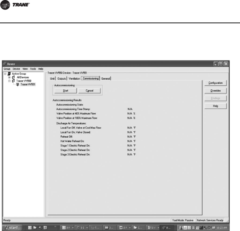
48 VAV-SVP01A-EN
VAV VV550 Controller Programming and Operation
Commissioning Tab
Auto-commissioning Test Sequence
The controller auto-commissioning test sequence (see Tab l e 9 , p. 49) validates both the proper
operation of all outputs and the capability to measure all inputs. The purpose of the test sequence
is to minimize the labor required to commission the unit in the field.
The auto-commissioning test does not require a flow sensor or an auxiliary temperature sensor.
If there is no flow sensor, the controller runs in pressure-dependent mode. An auxiliary
temperature sensor in the discharge air stream is required for testing of the fan and the reheat. The
fan and the reheat are not tested if the discharge air temperature sensor is not present. The fan is
not tested if there is no fan. Local reheat is tested, if it is present. Remote reheat is not tested.
The sequence starts on receipt of an auto-commission command from the Rover™ service tool or
the Tracer Summit™ BAS. The auto-commission command contains a time/date stamp. No third
party tool can start the auto-commissioning sequence. The user then chooses to commission all
VAV boxes or one VAV box. The results of auto-commissioning are contained in a structured
network variable called reported auto commissioning report. The controller places the time/date
stamp in the report. The structure is loaded with the default values for all of the fields when the auto
Figure 36. Commissioning tab

VAV-SVP01A-EN 49
VAV VV550 Controller Programming and Operation
commissioning test sequence starts. The fields are updated with the results as the sequence
progresses. The data is held until the next auto-commissioning test.
If an auto-commission command is received in the middle of an auto-commissioning cycle the
auto-commissioning sequence restarts. If an auto-commission command is received during
calibration, calibration aborts and restarts after auto-commissioning finishes. If an abort auto-
commission command is received during the calibration portion of the primary air valve test, it is
honored after the air valve calibration finishes.
The mode field of reported unit status reports TEST when the controller is in the auto-
commissioning sequence.
Table 9. Auto-commissioning test sequence
Item Test Action Reported Data
Primary air valve
and airflow(a)
1. Turn off fan and reheat.
2. Close air valve and modulating water valve (if present).
3. Calibrate the airflow sensor.
4. Open the air valve to 40% of the configured maximum airflow. Record the position of the air valve.
5. Open the air valve to 100% of the configured maximum airflow. Record the position of the air valve.
Primary air valve
position at 40% and
100% flow.
Fan Flow(b) 1. Record the auxiliary temperature at the configured maximum airflow.
2. Close the primary air valve.
3. Turn on the fan (if present).
4. Monitor auxiliary temperature for 3 minutes or until it changes by 10°F.
5. Record the auxiliary temperature.
Starting and ending
auxiliary
temperature.
Local Reheat
Hydronic(b)
1. If no fan is present, open the air valve to the configured minimum local heating airflow.
2. If the fan is present, close the air valve and turn on the fan.
3. Record the auxiliary temperature.
4. Open the water valve to 100% open.
5. Monitor the auxiliary temperature for 10 minutes or until it changes by 10°F.
Starting and ending
auxiliary
temperature.
Local reheat
electric(b) 1. If no fan is present, open the air valve to the configured minimum local heating airflow.
2. If the fan is present, close the air valve and turn on the fan.
3. Record the auxiliary temperature.
4. Progressively turn on each local stage 30 seconds after the previous stage until all stages are
energized.
5. Record the auxiliary temperature 30 seconds after each stage is energized.
Starting auxiliary
temperature and
the auxiliary
temperature for
each local stage of
electric heat
energized.
(a) If there is no flow sensor, the controller runs in pressure dependent mode and record 40% and 100% during this auto-commissioning step.
(b) Requires a functional auxiliary sensor in the discharge air stream. The auxiliary sensor must be configured for discharge air temperature.
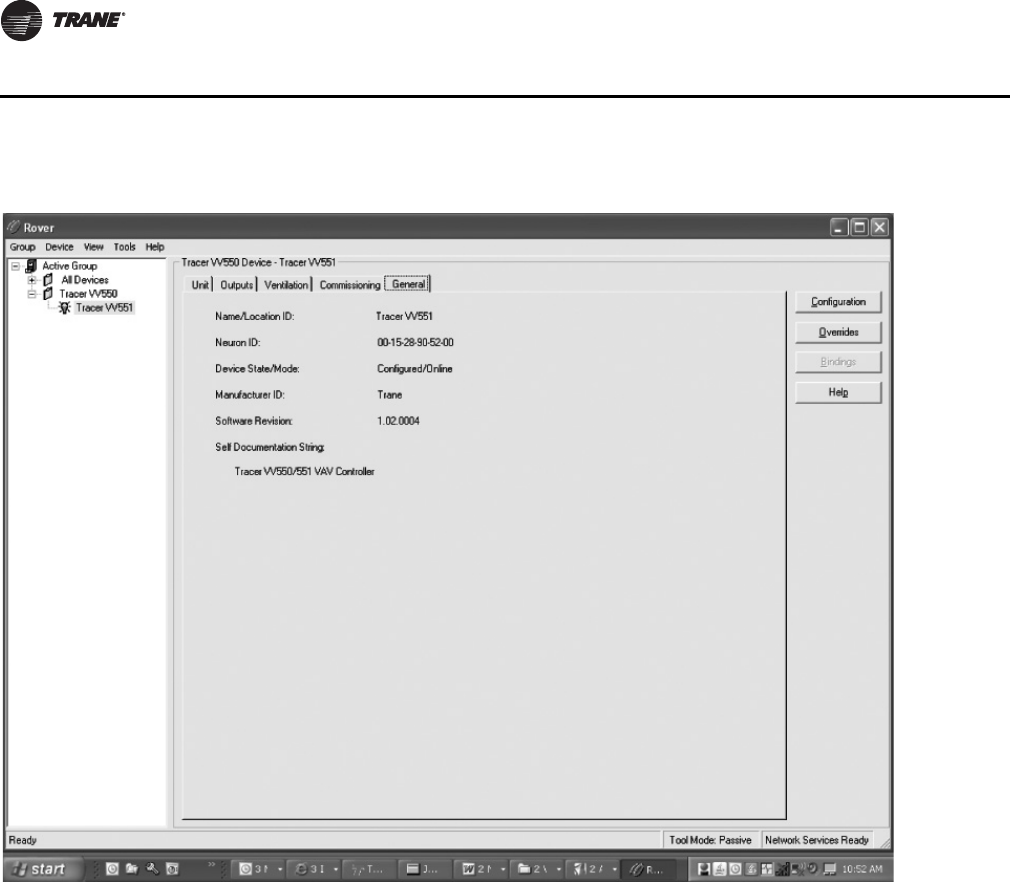
50 VAV-SVP01A-EN
VAV VV550 Controller Programming and Operation
Name Location/ID: VAV controller name
Neuron ID: Each VAV VV550 Controller will have an Echelon chip that has a distinctive
identification number called a neuron ID. This replaces the addressing that was done with dip
switches on a DDC Comm 4 VAV UCM 4.2 controller.
Device State/Mode: This point indicates if Rover is communicating with controller. The two
states are Configured On line or Not Communicating
Manufacturer ID: Trane will be the manufacture displayed for the VV550 controller
Software Revision: This is the controller revision programs that has been downloaded into this
controller
Note: If unit is not operating properly it could be a software issue and technical support will need
the revision number.
Self Documentation String: Indicates Tracer VV550/551 VAV controller.
Figure 37. General tab

VAV-SVP01A-EN 51
VAV VV550 Controller Programming and Operation
Entering and Exiting the Service Mode
Controllers must be online and in the service mode to receive an override. The service mode
disables control from VAV VV550 Controller and places Rover/Comm5 in command of the
controller. Controllers that are in the service mode appear in bold in the device tree on the left side
of your screen. More than one controller can be in the service mode at one time.
You can place a controller in the service mode manually or let Rover/Comm5 do so automatically
when you start an override. Controllers exit the service mode automatically 15 minutes after the
last override or when you manually release them.
To enter the service mode:
1. Connect to the Comm5 link and scan for devices.
2. In the device list on the left side of your screen, double-click the controller that you want to place
in the service mode.
3. Click the Enter Service Mode button. While the controller is in the service mode, it appears
in bold in the device list.
To exit the service mode, do one of the following:
• Wait for 15 minutes (Rover Comm5 does not need to be online with the controller).
• For each controller in the service mode, click the Exit Service Mode button.
Overriding VAVs
When you override a controller, Rover Comm5 automatically places the controller in the service
mode. The controller is automatically released from the service mode after 15 minutes or when you
click the Exit Service Mode button for the device. You can manually release overrides by selecting
the appropriate release command in the Override dialog box.
1. On the Tools menu, click Overrides.
2. Select override VAVs.
3. Click the units you want to override.
4. In the list of overrides, click the type of override you want to perform.
5. Click the Override button. The controller automatically enters the service mode and exits the
service mode 15 minutes after receiving an override.
Saving VAV Program
Each VAV unit with a VAV VV550 Controller has been factory commissioned with a program that
can be saved to your hard drive.
This can be used to save the original program for a backup in case unit needs to be put back to
original specifications or to download into a VAV VV550 Controller that has like parameters that has
been corrupted.
1. Select the Configure button, and the Configuration screen will appear.
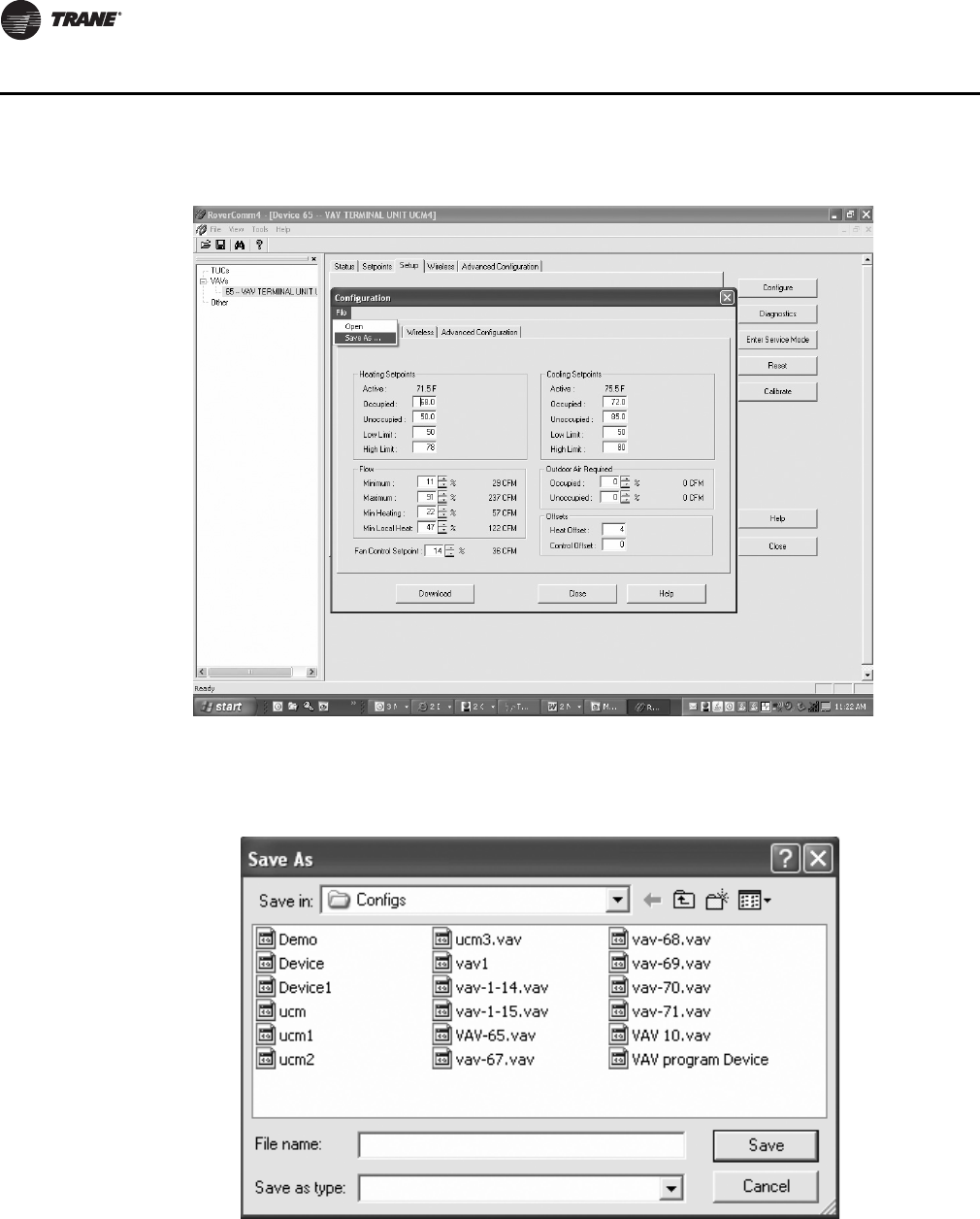
52 VAV-SVP01A-EN
VAV VV550 Controller Programming and Operation
2. Click the File menu and click Save As.
3. The Save As dialog box will appear. Name unit and click Save.
Downloading Program Files from PC to VAV VV550 Controller
1. Select the Configure button, and the Configuration screen will appear
Figure 38. Configuration screen (save as)
Figure 39. Save As prompt
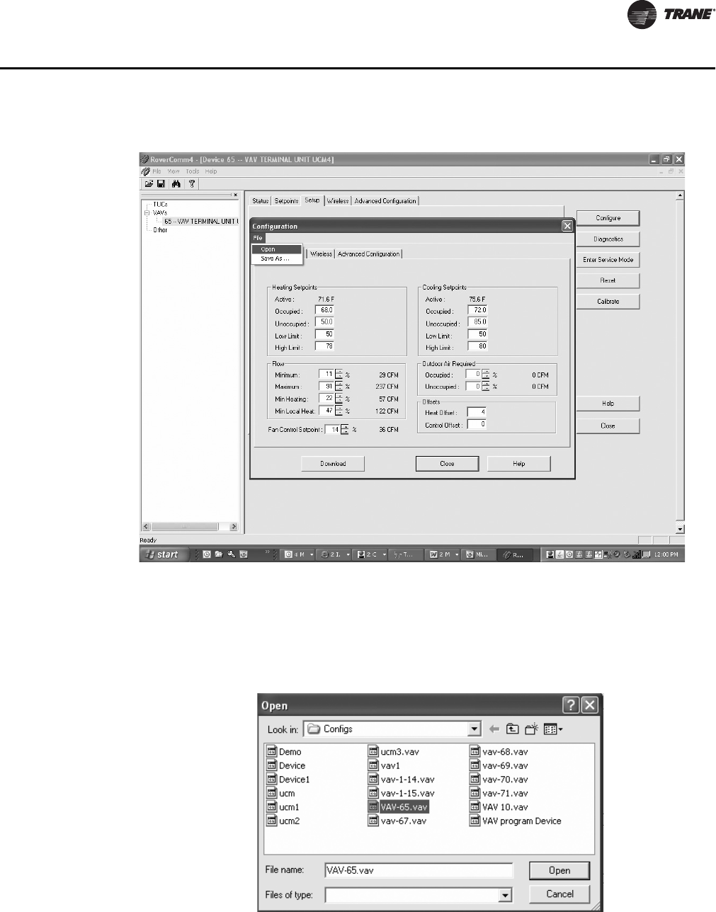
VAV-SVP01A-EN 53
VAV VV550 Controller Programming and Operation
2. Click the File menu and click Open.
3. The Open dialog box will appear. Select the file you wish to open and click the Open button.
4. Download to DDC VAV controller.
5. Program is now in controller.
Figure 40. Configuration screen (open)
Figure 41. Open dialogue box

54 VAV-SVP01A-EN
VAV VV550 Controller Device Home Tabs: Instructions
Chapter Overview
This chapter contains information about the following:
• Setpoints Tab
•Unit Tab
•Setup Tab
• Inputs Tab
•Outputs Tab
•Test Tab
•Other Tab
Configuration
To access the data fields for each tab and to make adjustments, select the Configure button. To
make adjustments, find the correct parameter, change it, and download to VV550.
Setpoints Tab
In Rover, the setpoints can be changed by selecting the Configure button. Following are
descriptions of each line on the Setpoints tab.
Default Setpoints
Unoccupied Cooling: Set points have a range of 30.0° - 100.0°F (-1.1° - 37.8°C). This cooling set
point is used when the VAV VV550 Controller is unoccupied. The unoccupied cooling set point must
be greater than or equal to the unoccupied heating set point plus 2.0°F 1.1°C).
Figure 42. Setpoints tab

VAV-SVP01A-EN 55
VAV VV550 Controller Device Home Tabs: Instructions
Occupied Standby Cooling: Based on the controller occupancy mode, the active space cooling
setpoint is the occupied stand by cooling setpoint, The controller can be placed in the occupied
standby mode when a communicated occupancy mode request (from a communicated occupancy
override, occupancy schedule, or occupancy sensor) is combined with an occupancy request from
the local (hardwired) occupancy binary input.
Note: This setpoint allows inactive spaces in the occupied mode to float to a more energy saving
setpoint until occupancy mode deems it necessary to use another setpoint as its active
setpoint.
Occupied Cooling: Set points have a range of 30.0°- 100.0°F (-1.1° - 37.8°C). If a zone sensor
thumbwheel set point is not being used, this set point will be used as the VAV VV550 Controller's
active cooling set point during occupied times. The cooling set point must be greater than or equal
to the heating set point plus 2.0°F (1.1°C).
Note: Occupied cooling and heating set points must be set within the cooling set point high limit
and the heating set point low limit in order to control to the proper setpoints.
Occupied Heating: Set points have a range of 30.0°- 100.0°F (-1.1° - 37.8°C). If a zone sensor
thumbwheel set point is not being used, this set point will be used as the VAV VV550 Controller's
active heating set point during occupied times. The cooling set point must be greater than or equal
to the heating set point plus 2.0°F (1.1°C).
Note: Occupied cooling and heating set points must be set within the cooling set point high limit
and the heating set point low limit in order to control to the proper setpoints.
Occupied Standby Heating: Based on the controller occupancy mode, the active space heating
setpoint is the occupied stand by heating setpoint, The controller can be placed in the occupied
standby mode when a communicated occupancy mode request (from a communicated occupancy
override, occupancy schedule, or occupancy sensor) is combined with an occupancy request from
the local (hardwired) occupancy binary input.
Note: This setpoint allows inactive spaces in the occupied mode to float to a more energy saving
setpoint until occupancy mode deems it necessary to use another setpoint as its active
setpoint.
Unoccupied Heating: Set points have a range of 30.0° - 100.0°F (-1.1° - 37.8°C). This heating set
point is used when the VAV VV550 Controller is unoccupied. The unoccupied cooling set point must
be greater than or equal to the unoccupied heating set point plus 2.0°F 1.1°C).
Active Setpoint
Space Temperature: The Active Space Temperature can be either from a local analog input, as
measured by the zone sensor, or as a remote communicated value. If both are present, the
controller uses the communicated value. The controller uses the network variable output space
temperature to report the space temperature value that it is using.
Active setpoint: The set point cannot be edited and reflects the set point currently being used for
Heating/Cooling temperature control. The Active Space Setpoint can be either from a local analog
input, as measured by the zone sensor, or as a remote communicated value. If both are present,
the controller uses the communicated value. The controller uses the network variable output
Effective setpoint to report the space active setpoint value that it is using.
Airflow: The airflow measured by the airflow sensor in the VAV box.
Setpoint Limits:
After the controller completes all setpoint calculations, the calculated occupied setpoint is
validated against the following configured space setpoint limits:
• Cooling Setpoint High Limit
• Cooling Setpoint Low Limit
• Heating Setpoint High Limit

56 VAV-SVP01A-EN
VAV VV550 Controller Device Home Tabs: Instructions
• Heating Setpoint Low Limit
These setpoint limits apply only to the occupied and occupied standby, heating and cooling
setpoints. They do not apply to the unoccupied heating and cooling setpoints. When the controller
is in the unoccupied mode, it always uses the unoccupied heating and cooling setpoints. Unit
configuration enables or disables the local (hardwired) setpoint. This parameter provides
additional flexibility to allow you to apply communicated, hardwired, or default setpoints without
making physical changes to the unit. Similar to hardwired setpoints, the effective setpoint value for
a communicated setpoint is determined based on the stored default setpoints, configuration
values, and the controller occupancy mode.
Freeze Avoidance
Outdoor Air Low Limit: Units with hot water coils installed are susceptible to freezing. Measures
must be taken to prevent the water coils from freezing. Freeze protection occurs only when the
controller is in the Off state or during the unoccupied period when the primary air valve is closed
and the reheat is disabled. During occupied operation, the control algorithm indirectly provides
freeze protection.
Note: On Ventilation Flow control mode with hot water only
Additional Fields
Enable Thumbwheel Setpoints: Unit configuration enables or disables the local (hardwired)
setpoint. This parameter provides additional flexibility to allow you to apply communicated,
hardwired, or default setpoints without making physical changes to the unit. If the thumbwheel is
not enabled, locally generated overrides (maximum flow or minimum flow) are not possible.
Enable Thumbwheel Star and Double Star Function: Single star and double star airflow
override capability can be disabled through configuration, while leaving the thumbwheel local
setpoint enabled. Positioning the thumbwheel at the single star (*) generates an override to cooling
minimum flow. The override is enabled when the setpoint is greater than 88°F (31.11°C) and
disabled when the setpoint is less than 87.7°F (30.94°C).
Positioning the thumbwheel at the double star (**) generates an override to cooling maximum
flow. The double star function is enabled when the setpoint is less than 48.5°F (9.17°C) and disabled
when the setpoint is greater than 50°F (10°C).
There is no effect on the fan and the reheat operation during the single star and double star
thumbwheel airflow overrides. When the single star and double star thumbwheel airflow overrides
are active, the default space setpoints are used, the reported local setpoint reports the invalid value.
Setpoint values outside of the valid setpoint range (50°F to 85°F [10.0°C to 29.44°C]) are not used.
Enable Auto calibration: Calibration takes place if this auto calibration feature is enabled and
either a power cycle or a transition from occupied to unoccupied has occurred. The building
automation system is responsible for the staggering of the calibration sequence that is needed
between units. When auto-calibration is enabled and a transition from occupied to unoccupied
occurs, the calibration sequence starts after a fixed delay of three minutes. The controller effective
occupancy mode is unoccupied, but runs like it is occupied during this three-minute period. The
mode field of reported unit status reports shows when the controller is in the calibration sequence.
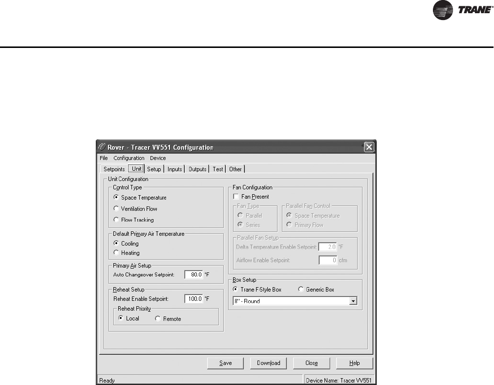
VAV-SVP01A-EN 57
VAV VV550 Controller Device Home Tabs: Instructions
Unit Tab
In Rover, the Unit Tab can be changed by selecting the Configure button. Following are
descriptions of each line on the Unit tab.
Unit Configuration
This allows for selection between three operational programs. The three programs are Space
Temperature, Ventilation Flow, and Flow Tracking
Note: See Operation chapter fore details on operational programs.
Default Primary Air Temperature
The selections are cooling or heating. The controller default operation (auto) can place the unit in
heating or cooling mode. When the controller automatically determines the heating or cooling
mode, the unit switches to the desired mode based on the primary air temperature.
Note: It can also be done with a communicated request.
Primary Air Setup
Auto Changeover Setpoint: The auto change over set point allows for switching from heating
to cooling operation with the vav) If primary air temperature greater than the configured auto
changeover setpoint, then primary air temperature is. (Primary air is hot enough for heating and
reheat can be used.) If primary air temperature < configured auto changeover setpoint - 10°F
(5.56°C), then primary air temperature is cold. (Primary air is cold enough for cooling and reheat
can be used.) No change in hysteresis region.
Reheat Setup
Reheat Enable Setpoint: When the primary air temperature is greater than the configured reheat
enable setpoint, reheat is turned OFF until the primary air temperature drops 5°F (2.78°C) below
Figure 43. Unit tab

58 VAV-SVP01A-EN
VAV VV550 Controller Device Home Tabs: Instructions
the configured reheat enable setpoint. The range for the Reheat enable setpoint for Hydronic heat
is 70°F to 200°F (21.11°C to 93.33°C) The range for the Reheat enable setpoint for Electric heat is 70°F
to 100°F [21.11°C to 37.78°C]).
Reheat Priority: Choices are Local and Remote. This area is available only if the controller is using
space temperature control.
• Local: Select this option to use local reheat before remote reheat.
•Remote: Select this option to use remote reheat before local reheat.
Fan Configuration
Fan Present: This dialog box should be checked if the unit has a fan. Rover automatically changes
the entry to 0 (None). When the value of this field is not None, the configuration of Output 3 is set
to Normally Open.
Fan Type: Select the type of fan used by the VAV VV550 Controller. If you edit the unit type field,
Valid Selections: Parallel, Series.
Parallel Fan Control: This entry will determine if a parallel fan will be controlled based on zone
temperature or on flow conditions. The entry field on this line will disappear if the unit does not
have a parallel fan.
Parallel Fan Setup: If "Parallel fan control" has been edited to "Space Temperature" the fan control
offset will be entered as a temperature offset (.3° - 8°F) which will be added to the heating set point.
If "Parallel fan control" has been edited to "Primary Flow" this line will be entered as a percent (0
to 100%)
Note: See the Sequence of Operations section of this manual for details on parallel fan operation.
Box Setup: Select the proper Setup type. The selectable item is either a "Trane F style" unit
manufactured by Trane or "Generic" if the VV550 controller is mounted on some one else's VAV
unit. The unit type information is maintained in the controller's EEPROM. When Trane F style unit
is selected it will also show the inlet size and type in inches. The entry field on this line will disappear
if the unit does not have Trane F style unit selected
Note: See CNT-PRC003-EN if retrofitting a VV550/1 controller onto someone else's VAV unit.
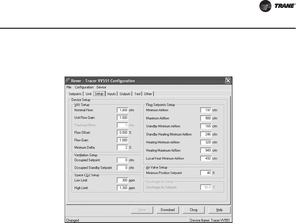
VAV-SVP01A-EN 59
VAV VV550 Controller Device Home Tabs: Instructions
Setup Tab
In Rover, the Setup Tab can be changed by selecting the Configure button. Following are
descriptions of each line on the Setup tab for the Device Setup.
VAV setu p
Nominal Flow: Nominal flow is the total airflow capacity of the VAV box. Nominal Flow becomes
an active field when "Generic" is selected in Box Setup under the Unit Tab. Select the CFM nominal
flow for the unit. This is normally used when mounting the VV551 controller on someone else's VAV
unit
Note: See CNT-PRC003-EN if retrofitting a VV550/1 controller onto someone else's VAV unit.
Unit Flow Gain: The flow gain is used to calibrate the value reported by the flow sensor so that
the reported airflow matches the actual airflow. The flow gain is determined during the air
balancing of system. A testing, adjusting, and balancing professional will use the Rover Air and
Water Balancing tool to calculate this value and balance the VAV box. Normally, you should not
need to change this value here.
Tracking Offset: This field is available only if the controller is using flow tracking control. Type
a tracking offset to create a positive or negative pressure in the controlled zone. The tracking offset
is added to the airflow setpoint, so a positive offset decreases the pressure in the zone, and a
negative offset increases the pressure in the zone. (A positive number decreases the pressure
because the flow tracking VAV box is removing air from the space.
Note: See Operation section for an explanation of flow tracking control.
If the flow sensor fails, the controller will control to the minimum flow setpoint if the flow tracking
offset is negative and to the maximum flow setpoint if the tracking offset is positive.
Flow Offset: The flow offset is used to calibrate the value reported by the flow sensor so that the
reported flow matches the actual flow. The flow offset is determined during the air balancing
process. A testing, adjusting, and balancing professional will use the Rover Air and Water
Figure 44. Setup tab

60 VAV-SVP01A-EN
VAV VV550 Controller Device Home Tabs: Instructions
Balancing tool to calculate this value and balance the VAV box. Normally, you should not need to
change this value here.
Note: The flow offset is calculated only for two-point balancing, which requires reading both the
maximum and minimum airflows during balancing. Two-point balancing ensure greater
accuracy over the entire range of air valve operation. Only controllers that support the Flow
Measurement Offset network variable, such as the VAV VV550/551 Controller, can use two-
point balancing.
Flow Gain: The flow gain is used to calibrate the value reported by the flow sensor so that the
reported airflow matches the actual airflow. The flow gain is determined during the air balancing
process. A testing, adjusting, and balancing professional will use the Rover Air and Water
Balancing tool to calculate this value and balance the VAV box. Normally, you should not need to
change this value here.
Minimum Delta: The minimum amount of change in the primary airflow required before airflow
and the airflow setpoint are communicated on the Comm5 link. The percentage of change required
is based on the nominal airflow. For example, if the nominal airflow is 1000 cfm and the minimum
delta is 2%, the primary airflow must increase or decrease by 20 cfm before the change is
communicated on the Comm5 link.
Ventilation Setup
A Tracer Summit building automation system is required for accurate ventilation control. The
Tracer Summit VAS Comm5 application calculates the ventilation setpoint and coordinates the air
handler and VAV boxes.
Occupied Setpoint: During the occupied mode, this setpoint is the active setpoint for ventilation.
Occupied Standby Setpoint: During the unoccupied mode, this setpoint is the active setpoint
for ventilation.
Space CO2 Setup (CO2 sensor communicated value only)
Low Limit: The controller adjusts the ventilation setpoint only when the CO2 concentration falls
within the high and low limits. When the CO2 concentration falls below the low limit, this indicates
that the zone is most likely unoccupied and that a minimum of ventilation air is required to ventilate
the zone.
High Limit: The controller adjusts the ventilation setpoint only when the CO2 concentration falls
within the high and low limits. When the CO2 concentration rises above the high limit, this indicates
that the zone is most likely at its maximum design occupancy and that a maximum of ventilation
air is required to ventilate the zone.
Flow Setpoints Setup
Minimum Airflow: Although the VAV VV550 Controller will read flow down to 5% of cataloged,
the range of MIN FLOW settings is 0%, or 10% to 100% of cataloged. The VAV VV550 Controller will
not drive its flow below this minimum flow value under normal operating conditions while in the
cool mode. Cool mode occurs when cool air is in the supply duct. The entry in the Cooling Minimum
field must be less than or equal to the entry in the Maximum field.
Maximum Airflow: This range is 10% to 100% of the unit's cataloged CFM size. Cooling and
heating flow can be edited to zero.The VAV VV550 Controller will not drive its flow above this
maximum flow value under normal operating conditions while in the Cool mode. Cool mode
occurs when cool air is in the supply duct. The entry for Maximum Flow must be greater than or
equal to the entry in any of the Minimum fields.
Standby Minimum Airflow: Occupied standby mode is used to reduce the heating and cooling
demands during the occupied hours when the space is unoccupied. It can be activated for a
classroom currently not in use. Standby Minimum is the minimum amount of airflow desired
during this mode.
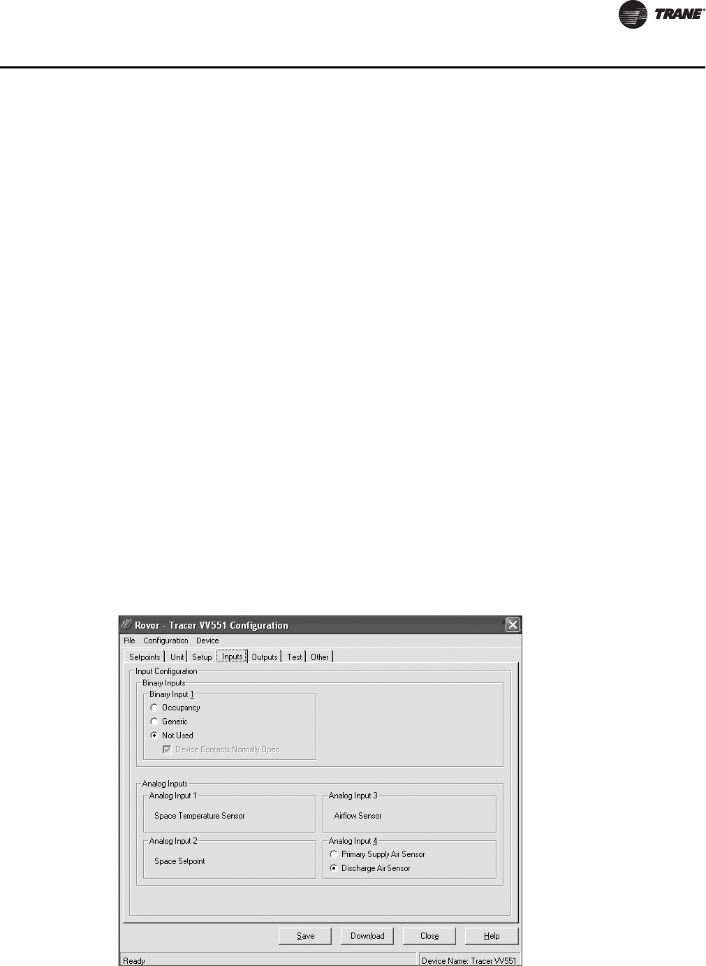
VAV-SVP01A-EN 61
VAV VV550 Controller Device Home Tabs: Instructions
Standby Heating Minimum Airflow: Occupied standby mode is used to reduce the heating and
cooling demands during the occupied hours when the space is unoccupied. It can be activated for
a classroom currently not in use. Standby Heating Minimum is the minimum amount of airflow
desired when in the heat mode during this mode.
Heating Minimum Airflow: The VV550 will not drive its position/flow below this value under
normal operating conditions while in the HEAT mode (warm air in the supply duct) or while it is
using local heat.
Heating Maximum Airflow: The controller enters maximum flow heat on receipt of a
communicated command and remains in maximum flow heat until the command changes. The
controller maintains the flow rate at the heating maximum airflow. This is normally used with a
rooftop unit with staged heat that needs a Max constant volume of air movement to keep the heat
exchanger from overheating and tripping the heat in the rooftop unit tripping on a high limit safety.
Local Heat Minimum Airflow: If the Min Local Heat flow is enabled, then the Min Local Heat flow
is used to determine the minimum position/flow instead of the Min Heating Flow when local heat
is on. The entry for Min Heating Flow must be less than or equal to the entry for the Maximum Flow.
Air Valve Setup
Minimum Position Setpoint: Type the minimum position for the air valve during the pressure
dependent mode.
Discharge Air Setup
Discharge Air Setpoint: Type the discharge-air setpoint. This field is available only if you
selected ventilation flow control on the Unit tab. When using ventilation flow control and in the
occupied mode, the VAV VV550 Controller controls to the active airflow setpoint and modulates the
heating capacity to keep the discharge-air temperature at the active discharge-air temperature
setpoint.
Inputs Tab
Figure 45. Inputs tab

62 VAV-SVP01A-EN
VAV VV550 Controller Device Home Tabs: Instructions
In Rover, the Inputs tab can be changed by selecting the Configure button. Following are
descriptions of each line on the Inputs tab. For a factory-installed VAV VV550 Controller, all inputs
and outputs are configured at the factory. For a field-installed VAV VV551 Controller, use this tab
to configure the inputs.
Binary Input 1
Select the application used with Binary input 1.
Occupancy: Select this option to use binary input 1 to detect the occupancy mode from an
occupancy sensor.
Generic: Select this option to use binary input 1 as a generic input.
Not Used: Select this option if binary input 1 is not used.
Device Contacts Normally Open: Select this check box if the device contacts are normally open.
Analog Input 1
This area displays Space Temperature Sensor when the analog input is connected to a zone
sensor. Analog input 1 can be used only to read the space temperature from a zone sensor. The
controller can receive the space temperature from either analog input 1 or as a communicated
value. If both are present, the controller uses the communicated space temperature.
Analog Input 2
This area displays Space Setpoint when the analog input is connected to a zone sensor. This input
can be used only to read the local space temperature setpoint from the zone sensor.
Analog Input 3
This area displays Airflow Sensor when the analog input is connected to an airflow sensor. The
controller can operate without a valid airflow value (either hardwired or communicated).
Analog Input 4
Select the application used with analog input 4. The sensor must be a 10 k thermistor.
Primary Supply Air Sensor: Select this option if the sensor measures the primary air
temperature. In this case, the sensor must be located upstream from the unit.
The controller can receive the primary air temperature from the analog input or as a communicated
value. If both are present, the controller uses the communicated temperature. If neither is present,
the controller uses the default primary air temperature defined on the Unit tab (either hot or cold).
Discharge Air Sensor: Select this option if the sensor measures the discharge-air temperature.
In this case, the sensor must be located downstream. The controller can operate without a valid
discharge-air temperature analog input if configured for space temperature control or flow tracking
control. If the controller is using ventilation flow control with reheat, the unit shuts down if there
is no valid discharge-air temperature. A ventilation flow control unit without reheat operates
normally without a valid discharge-air temperature.
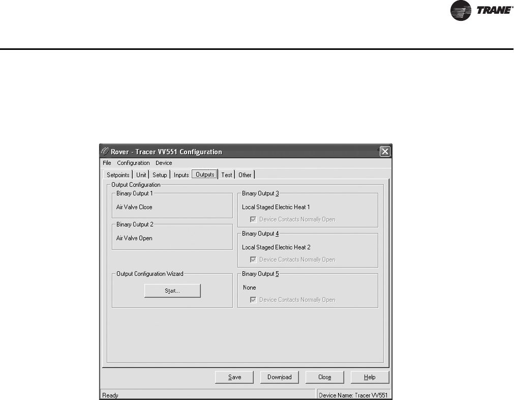
VAV-SVP01A-EN 63
VAV VV550 Controller Device Home Tabs: Instructions
Outputs Tab
In Rover, the Outputs Tab can be changed by selecting the Configure button. Following are
descriptions of each line on the Outputs tab. For the factory-installed VAV VV550 Controller, all
inputs and outputs are configured at the factory. For the field-installed VAV VV551 Controller, click
the Start button to configure the outputs.
Binary Output 1
Binary output 1 is used to drive the air valve closed. It works in conjunction with binary output 2
to modulate the air valve.
Binary Output 2
Binary output 1 is used to drive the air valve open. It works in conjunction with binary output 1 to
modulate the air valve.
Output Configuration Wizard
Click the Start button to configure the outputs.
Binary Output 3& 4
This output can be configured for:
• Hot-water on/off control
• Hot-water modulating (3-wire) valve control (requires outputs 3 and 4)
• Electric-heat staged or pulse width modulation
The output is automatically configured based on your answers in the Output Configuration Wizard.
Device Contacts Normally Open: Select this check box if the device contacts are normally open.
This check box is available only for hot-water on/off control.
Figure 46. Outputs tab
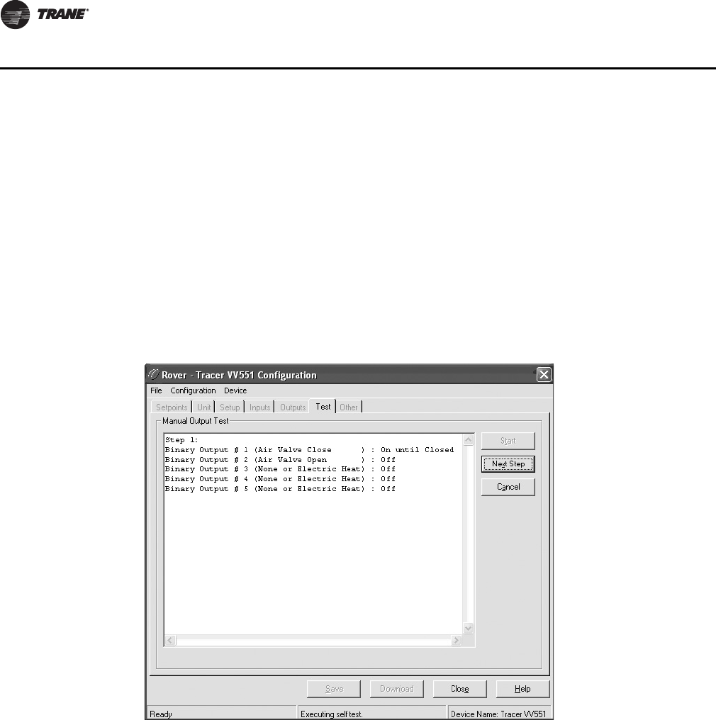
64 VAV-SVP01A-EN
VAV VV550 Controller Device Home Tabs: Instructions
Binary Output 5
This output can be configured for:
• Parallel or series fan on/off control
• Hot-water on/off control
• Electric-heat staged or pulse width modulation
The output is automatically configured based on your answers in the Output Configuration Wizard.
Device Contacts Normally Open: Select this check box if the device contacts are normally open.
This check box is available only for hot-water on/off control.
Test Tab
Use the Test tab to exercise the binary outputs and verify that they are working correctly.
To perform a manual output test:
1. Click the Start button.
2. Click the Next Step button repeatedly to step through the test.
3. Click the Cancel button to stop the test.
Figure 47. Test tab
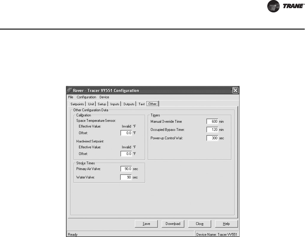
VAV-SVP01A-EN 65
VAV VV550 Controller Device Home Tabs: Instructions
Other Tab
In Rover, the Other Tab can be changed by selecting the Configure button. Following are
descriptions of each line on the Other tab. Use this tab to calibrate sensors and set up timers.
Calibration
Space Temperature Sensor: Use this area to calibrate the space temperature. The effective value
is the result of the space temperature used by the controller plus the offset value. In the Offset field,
type a negative or positive number to offset the space temperature.
Hardwired Setpoint: Use this area to calibrate the setpoint from the zone sensor. The effective
value is the result of the raw value of the hardwired setpoint plus the offset value. In the Offset field,
type a negative or positive number to add to the hardwired setpoint. After calibration, the effective
value should match the value indicated on the zone sensor thumbwheel.
Stroke Times
Primary Air Valve: Type the amount of time required to drive the air valve from fully open to fully
closed or vice versa. For field-installed VAV VV551 Controllers, this value must be changed to match
the specifications of the air valve.
Water Valve: Type the amount of time required to drive the water valve from fully open to fully
closed or vice versa. For field-installed VAV VV551 Controllers, this value must be changed to match
the specifications water valve.
Timers
Manual Override Time: Type the amount of time that the controller will remain in override. After
this time passes, air- and water-valve overrides are released automatically. Fan overrides do not
release automatically.
Figure 48. Other tab
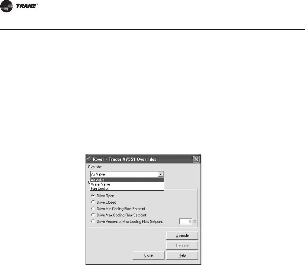
66 VAV-SVP01A-EN
VAV VV550 Controller Device Home Tabs: Instructions
Occupied Bypass Timer: Type the amount of time that the controller remains in the occupied
bypass mode. If the controller is in the unoccupied mode and an occupant presses the On button
at the zone sensor, the controller goes into occupied bypass mode for this amount of time.
Power-up Control Wait: Type the number of seconds you want the controller to wait after startup
before starting normal operation. When power-up control wait is enabled (whenever a time is
entered here), the controller remains off until one of two conditions occurs:
• Controller receives communicated information on the Comm5 link
• Power-up control wait time expires
Note: If auto calibration is enabled, the controller will calibrate during power-up control wait.
Overrides
To access the data fields for each tab and to make adjustments, select the Overrides button.
In the Override list, select the valve or fan you want to override. The types of overrides you can
perform change based on your selection.
Change/Override
In the Change/Override area, select the type of override you want to perform, then click the Override
button.
Override button: Click this button to start the override.
Release button: Click this button to release any existing overrides for the VAV VV550 Controller.
If you do not release the overrides here, the controller automatically releases them after 10 hours
by default for air valves and water valves. You can change this default in the Timers area on the
Other tab in the Configuration dialog box. The controller does not automatically release fan
overrides.
Close button: Click this button to exit the Device Overrides dialog box.
Figure 49. Overrides

VAV-SVP01A-EN 67
Sequence of Operations
Chapter Overview
This chapter contains information about the following:
• Calibration
• Occupancy Modes
• Space Temperature Control: Single Duct Units
• Space Temperature Control: Fan-Powered Units
• Ventilation Flow Control
•Flow Tracking
Normal Operation
The controller is functioning normally when it is operating in one of the three control modes (space
temperature control, ventilation control, or flow tracking control) and in one of four occupancy
modes (occupied mode, unoccupied mode, occupied standby mode, or occupied bypass mode).
Note: For More detail on control modes and units operation see CNT-SVX17*-EN.
Calibration
The calibration sequence enables the controller to calibrate the air valve position and the water
valve position. Calibration takes place if autocalibration is enabled and either a power cycle or a
transition from occupied to unoccupied has occurred.
Note: Whether or not autocalibration is enabled, the controller initiates calibration on a
communicated application mode command.
The building automation system is responsible for the staggering of the calibration sequence that
is needed between units. When autocalibration is enabled and a transition from occupied to
unoccupied occurs, the calibration sequence starts after a fixed delay of three minutes. The
controller effective occupancy mode is unoccupied, but runs like it is occupied during this three
minute period. The mode field of reported unit status reports calibration when the controller is in
the calibration sequence. If autocalibration is disabled, the air valve and water valve are not driven
closed and the flow sensor zero flow voltage reading is not recorded. Refer to Table 10, p. 67 for
calibration actions.
Table 10. Calibration actions
I/O Device Calibration Action Taken Result After Calibration
Air valve Drive the air valve closed to the stroke time plus 20 seconds initialize the air valve position as closed when
the air valve is over-driven
Flow sensor Record the flow reading when the air valve is fully closed Subtract the zero flow reading from all
subsequent readings
Modulating hot water reheat Drive the water valve closed for the stroke time plus 20 seconds initialize the water valve position as closed when
the water valve is over-driven
Fan Enabled Enabled
Electric or On/Off hot water Disabled Enabled

68 VAV-SVP01A-EN
Sequence of Operations
Occupancy Modes
VAV VV550 Controllers have four valid occupancy modes: Occupied, Unoccupied, Occupied
standby, and Occupied Bypass.
Occupied Mode
Occupied mode is the normal (default) operating mode for occupied spaces or daytime operation.
When the controller is in the occupied mode, it uses occupied setpoints and runs in:
• Occupied temperature control;
• Ventilation flow control or space temperature control;
• Flow tracking control.
Unoccupied Mode
Unoccupied mode (also known as night setback) is the normal operating mode for unoccupied
spaces or nighttime operation. Unoccupied setpoints enable or disable occupied space
temperature control.
When the controller is in the unoccupied mode and configured for space temperature control, the
controller attempts to keep the space temperature between the active unoccupied heating setpoint
and the active unoccupied cooling setpoint. When the controller is in the unoccupied mode and
configured for ventilation flow control, it will not run in unoccupied mode, the air valve is closed,
and local heat is disabled.
A flow tracking controller runs the same as when it is occupied. When the controller is in the
unoccupied mode and configured for flow tracking control, it runs the same as it does in occupied
mode.
Occupied Standby Mode
Occupied standby mode is used to reduce the heating and cooling demands during the occupied
hours when the space is unoccupied. It can be activated for a classroom currently not in use.
The controller can be placed in the occupied standby mode when a communicated occupancy
mode request (from a communicated occupancy override, occupancy schedule, or occupancy
sensor) is combined with an occupancy request from the local (hardwired) occupancy binary input.
Once in occupied standby mode, the controller uses the occupied standby cooling and heating
setpoints, which typically cover a wider range than the occupied setpoints. The wider range
reduces the demand for heating and cooling in the space.
When the communicated occupancy mode request is unoccupied, the occupancy binary input
signal (if present) does not affect the controller occupancy mode. When the communicated
occupancy mode request (communicated occupancy override not valid, communicated occupancy
schedule occupied, or communicated occupancy sensor not valid) is occupied, the controller uses
the local occupancy binary input to switch between the occupied and occupied standby modes.
When the controller is in the occupied standby mode, it uses occupied standby setpoints and runs
in:
• Occupied temperature control;
• Ventilation flow control or space temperature control;
• Flow tracking control.
Occupied Bypass Mode
Occupied bypass mode is used for timed overrides. For example, if the controller is in unoccupied
mode or occupied standby mode, pressing the zone sensor ON button places the controller in
occupied bypass mode for 120 minutes (default configured occupied bypass time) or until
someone presses the zone sensor CANCEL button. The controller can be placed in occupied bypass

VAV-SVP01A-EN 69
Sequence of Operations
mode by either communicating an occupancy mode request of bypass mode (communicated
occupancy override) to the controller or by using the zone sensor timed override ON button. The
occupied bypass mode and the occupied mode operate similarly.
When the controller is in the unoccupied mode, pressing the zone sensor ON button places the
controller in the occupied bypass mode for the duration of the configured occupied bypass time.
When the controller is in the occupied standby mode, pressing the zone sensor ON button places
the controller in the occupied bypass mode for the duration of the configured occupied bypass
time.
Space Temperature Control: Single Duct Units
Space temperature control (STC) is one of three supported control algorithms. Space temperature
control requires a valid space temperature. If there is no valid space temperature (communicated
or local), the space temperature control algorithm does not run; the unit either shuts down or goes
to construction mode.
VAV VV550 Controllers use the active space temperature to maintain the space temperature at the
active space cooling setpoint or the active space heating setpoint.
The controller heat/cool mode is determined by either a communicated request or by the controller
itself, when the heat/cool mode is auto. When the heat/cool mode is auto, the controller compares
the primary air temperature with the configured auto-changeover setpoint to determine if the
primary air is hot or cold. This is called autochangeover. This determination may differ from the
reported heat/cool mode, which matches the zone demand.
The control compares the active space setpoint and the active space temperature and calculates
the desired capacity. The control positions the modulating air valve to deliver the desired airflow
(cooling or heating capacity).
Cooling Operation
Under space temperature control during the cooling mode (communicated heat/cool mode is cool),
the controller attempts to maintain the active space temperature at the active space cooling
setpoint. Based on the controller occupancy mode, the active space cooling setpoint is either the
occupied cooling setpoint, the occupied standby cooling setpoint, or the unoccupied cooling
setpoint.
The outputs are controlled based on the unit configuration and the required cooling capacity. At
0% required cooling capacity, the air valve is closed or at the active minimum flow setpoint. As the
required cooling capacity increases, the air valve opens above the minimum position. At 100%
required cooling capacity, the air valve opens to the maximum position or to the active maximum
flow setpoint.
All units have a modulating air valve. The modulating air valve is used to control the volume of air
flowing through the diffusers and into the space. Modulating the volume of air modulates the unit
cooling capacity.
Also, units may have local or remote reheat. The reheat may be hydronic or electric. Reheat is
allowed to turn On when the space temperature is below the heating setpoint
Heating Operation
Under space temperature control, during the heating mode (communicated heat/cool mode is
heat), the controller attempts to maintain the space temperature at the active heating setpoint.
Based on the controller occupancy mode, the active space heating setpoint is either the occupied
heating setpoint, the occupied standby heating setpoint, or the unoccupied heat setpoint. All
ventilation requirements are in force during occupied heating and cooling.
The outputs are controlled based on the unit configuration and the required heating capacity. At
0% required heating capacity, the air valve is at its minimum flow setpoint. As the required heating

70 VAV-SVP01A-EN
Sequence of Operations
capacity increases, the air valve opens above its minimum position. At 100% required heating
capacity, the air valve opens to its maximum position.
All units have a modulating air valve. The modulating air valve is used to control how much air is
flowing through the diffusers and into the space. By modulating the volume of air flowing, the unit
heating capacity is modulated.
Units may also have local or remote reheat. This reheat may be hydronic or electric. Reheat is used
to maintain the space temperature at the heating setpoint.
Note: Heating operation and Reheat are to different entities.
Air Valve Control in Space Temperature Control Operation
Air delivered to the space is controlled with a three-wire floating-point actuator that modulates the
air valve. The controller positions the modulating air valve to deliver the desired airflow (cooling
or heating capacity). The desired airflow is called the active-flow setpoint. The controller positions
the modulating air valve to deliver the desired airflow (cooling and heating capacity) to within +/
-2% of nominal airflow.
The airflow control algorithm compares the active airflow setpoint with the measured airflow and
calculates the necessary air valve movement to minimize error. The airflow setpoint is limited by
applicable minimum and maximum flow setpoints.
Reheat Control
There are two types of reheat control: hydronic heat and electric heat. Reheat is allowed to turn On
if the zone temperature is below the heating setpoint. Space temperature control can use reheat
if the following conditions are all true:
• The unit is not calibrating;
• Reheat is enabled (communicated auxiliary heat enable);
• For local reheat only, the fan, if present, is not being overridden to Off (communicated fan speed
command);
• The primary air temperature is less than the configured reheat enable setpoint (5°F [2.78°C]);
• Local heat minimum airflow is used for both local and remote reheat.
Electric Heat
Pulse-Width Modulation of Electric Heat
One to three stages of pulse-width modulation of electric heat are available on single duct units and
fan powered units up to two stages are available for PWM heat control. Energizing for a portion of
a three-minute time period modulates the electric heater. This allows exact load matching for
energy efficient operation, and optimum zone temperature control. The heating minimum airflow
setpoint is enforced during reheat. The amount of reheat supplied is dependent on both the degree
that the space temperature is below the active heating setpoint and the time that the space
temperature has been below the active heating setpoint. If not already off, reheat de-energizes
when the zone temperature rises more than 0.5°F (0.28°C) above the heating setpoint.
The Stage 1 "on" time is proportional to the amount of reheat required. For example, when 50%
of stage 1 capacity is required, reheat is on for 90 seconds and off for 90 seconds. When 75% of
stage 1 capacity is required, reheat is on for 135 seconds and off for 45 seconds. When 100% of
stage 1 capacity is required, reheat is on continuously.
Stage 2 uses the same "on" time logic as stage 1 listed above, except stage 1 is always energized.
For example, when 75% of unit capacity is required, stage 1 is energized continuously, and stage
2 is on for 90 seconds and off for 90 seconds. When reheat is deenergized, the cooling minimum
airflow setpoint is activated.
Important: Leaving air temperatures (LAT) should not exceed 100°-110°F, with 95°F being the
optimal for zone temperature and comfort control. At elevated LATs, room

VAV-SVP01A-EN 71
Sequence of Operations
stratification may result in uneven air distribution and zone temperature complaints.
See Table 11, p. 72 for single duct reheat operation and Table 12, p. 72 for fan
powered reheat operation.
On/Off Electric Reheat
One, two, or three stages of staged electric reheat are available on single duct units and two sages
of electric heat are available on fan powered units. The heating minimum airflow setpoint is
enforced during reheat.
• Stage 1 is energized when the space temperature falls below the active heating setpoint and
minimum airflow requirements are met. When the zone temperature rises above the active
heating setpoint by 0.5°F (0.28°C), stage 1 is de-energized.
• Stage 2 energizes when the space temperature is 1°F (0.56°C) or more below the active heating
setpoint, and is de-energized when the space temperature is 0.5°F (0.28°C) below the active
heating setpoint.
• Stage 3 energizes when the zone temperature is 2°F (1.11°C) or more below the active heating
setpoint, and de-energizes when the space temperature is 1.5°F (0.83°C) below the active
heating setpoint.
When reheat is de-energized, the cooling minimum airflow setpoint is activated. See Tab l e 11, p . 7 2
for single duct reheat operation and Table 12, p. 72 for fan powered reheat operation.
Hot Water Heat
Two types of control of hydronic heat are supported: On/Off and modulating.
Note: Steam is not supported.
Hydronic heat is enabled if there is no valid primary air temperature. Hydronic heat is disabled if
the primary air temperature is greater than the configured reheat enable setpoint.
ON/Off Hot Water Heat
Refer to staged electric heat for operation. Difference is we are controlling a two position hot water
valve instead of contactor energizing an electric heat strip. See Table 11, p . 7 2 for single duct reheat
operation and Table 12, p. 72 for fan powered reheat operation.
Proportional Hot Water Reheat
Proportional hot water reheat uses 3- wire floating-point-actuator technology. It is the same
operation for single duct units as it is for fan powered units. The heating minimum airflow setpoint
is enforced during reheat. The water valve opens as space temperature drops below the heating
setpoint. A separate reheat proportional plus- integral control loop from that controlling airflow
into the room is enforced. Water valve position is dependent on the degree that the space
temperature is below the active heating setpoint and the time that the space temperature has been
below the active heating setpoint. If not already closed, the water valve fully closes when the zone
temperature rises above the active heating setpoint by 0.5 °F (0.28 °C). An additional on/off remote
heat output is available and energized when the proportional valve is driven 100% open and de-
energized when the proportional valve reaches 50% open. When reheat is de-energized, the cooling
minimum airflow setpoint is activated See Table 11, p. 72 for single duct reheat operation and
Ta ble 12 , p . 72 for fan powered reheat operation.
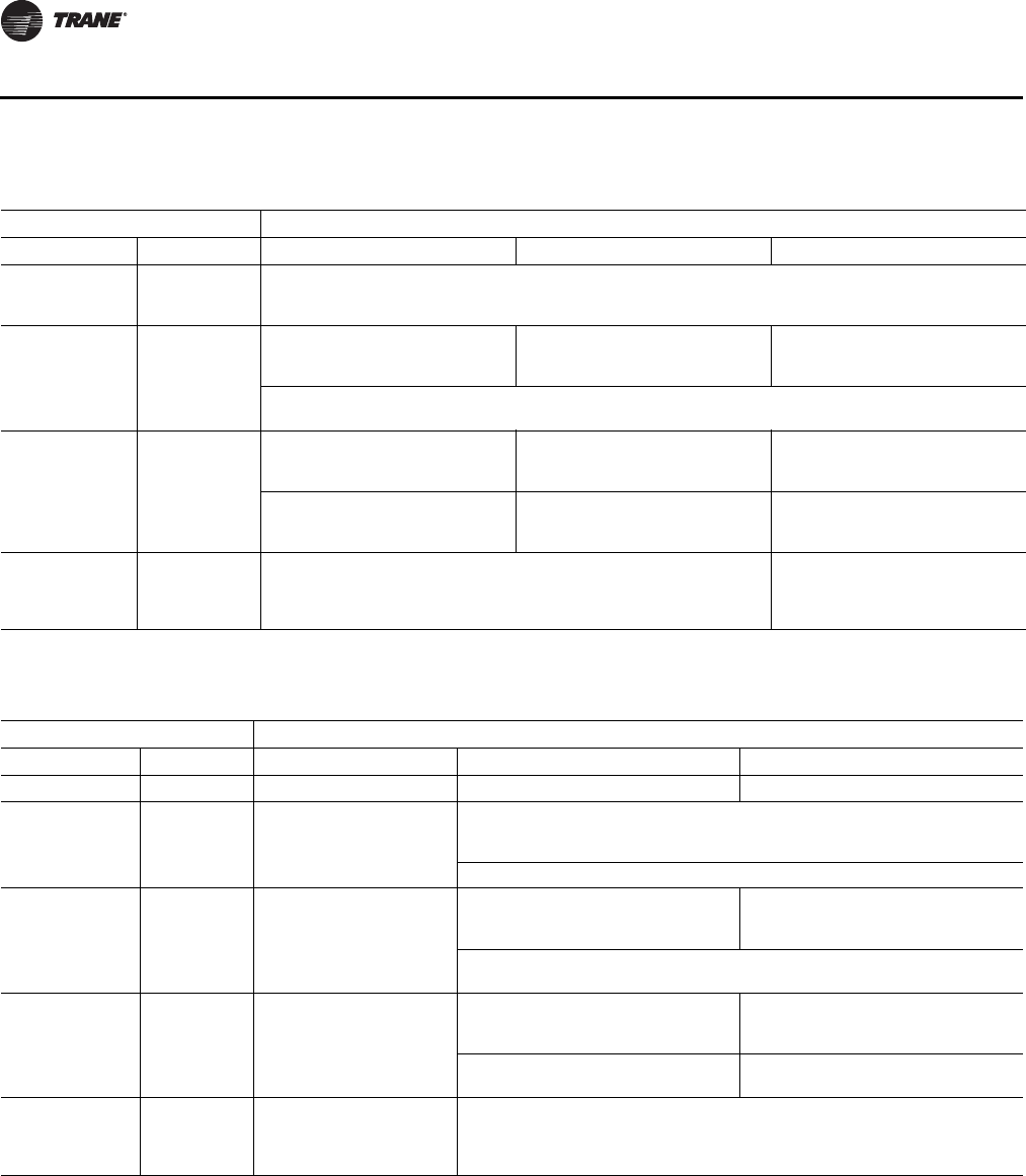
72 VAV-SVP01A-EN
Sequence of Operations
Space Temperature Control: Fan-Powered Units
VAV VV550/VV551 Controllers provide three fan options when in space temperature control mode:
• One-speed ON/OFF series fan;
• One-speed ON/OFF parallel fan;
• Fan Off Delay
Table 11. Local heat only with no fan present
Configuration Method of control
Local Remote Stage 1 Stage 2 Stage 3
PWM electric
(1 to 3 stages)
Not applicable Local PI capacity loop
Each stage represents an equal percentage of total capacity PWM Output (one stage = 100%; two stages
= 50% each; three stages = 33.33% each). Total capacity is limited by communicated auxiliary heat enable.
On/Off electric
(1 to 3 stages)
Not applicable Local thermostatic
On: Zt < HSP
Off: Zt ≥ HSP + 0.5°F (0.28°C)
Local thermostatic
On: Zt < HSP - 1°F (0.56°C)
Off: Zt ≥ HSP - 0.5°F (0.28°C)
Local thermostatic
On: Zt < HSP - 2°F
Off: Zt ≥ HSP - 1.5°F
Each stage represents an equal percentage of total capacity. Total capacity is limited by communicated
auxiliary heat enable.
On/Off hot water
(1 stage)
Not applicable Local thermostatic
On: Zt < HSP
Off: Zt ≥ HSP + 0.5°F (0.28°C)
Not applicable Not applicable
Total capacity is limited by
communicated auxiliary heat
enable.
Not applicable Not applicable
Modulating hot
water
Not applicable Local PI capacity loop
Modulating valve capacity = Total capacity
Valve drive Incrementally open/closed
Total capacity limited by communicated auxiliary heat enable
Not applicable
Note: Abbreviations: Zt = Zone temperature; HSP = Heating setpoint
Table 12. Local heat only with parallel/series fans present
Configuration Method of control
Local Remote Stage 1 Stage 2 Stage 3
Fan Not applicable Parallel/Series Fans Not applicable Not applicable
Fan +
PWM electric
(1 to 2 stages)
Not applicable Parallel/Series Fans Local PI capacity loop
Each stage represents an equal percent of total capacity (1-stage = 100%, 2
stages = 50% each) PWM output
Total capacity is limited by communicated auxiliary heat enable.
Fan +
On/Off electric
(1 to 2 stages)
Not applicable Parallel/Series Fans Local thermostatic
On: Zt < HSP - 1°F (0.56°C)
Off: Zt ≥ HSP - 0.5°F (0.28°C)
Local thermostatic
On: Zt < HSP - 2°F (1.11°C)
Off: Zt ≥ HSP - 1.5°F (0.83°C)
Each stage represents an equal percentage of total capacity. Total capacity is
limited by communicated auxiliary heat enable.
Fan +
On/Off hot water
(1 to 2 stages)
Not applicable Parallel/Series Fans Local thermostatic
On: Zt < HSP - 1°F (0.56°C)
Off: Zt ≥ HSP - 0.5°F (0.28°C)
Not applicable
Total capacity is limited by
communicated auxiliary heat enable Not applicable
Fan +
Modulating hot
water
Not applicable Parallel/Series Fans Local PI capacity loop
Modulating valve capacity = Total capacity
Valve drive incrementally open/closed
Total capacity limited by communicated auxiliary heat enable
Note: Abbreviations: Zt = Zone temperature; HSP = Heating setpoint

VAV-SVP01A-EN 73
Sequence of Operations
This Comm5 controller supports an Electronically Commutated Motor (ECM). The controller turns
the ECM fan On and Off. It does not change the ECM fan airflow. To assist with flow balancing the
fan flow rate is stored as a configuration item.
Series Fan
The series fan is always controlled as a one-speed ON/OFF fan. The fan operates continuously in
the occupied or occupied standby mode. The fan cycles ON and OFF with calls for heating or
cooling in the unoccupied mode. The series fan operates in a manner that prevents reverse
rotational operation. The series fan is turned ON whenever one of the following occurs:
• Target airflow control point is greater than zero;
• Target air valve position is not closed;
• Actual air valve position is not closed.
Series fan operation during calibration
During calibration, the series fan is OFF unless the power-up control wait timer reaches zero. When
the power-up control wait timer reaches zero, the controller uses the normal series fan control logic.
The series fan is turned OFF for 10 seconds during calibration after the air valve closes all the way.
And, it remains OFF after the 10 seconds expires if:
• Power-up control wait time is still active;
• System mode (communicated application mode or communicated heat/cool mode) is ON;
• Effective occupancy mode is unoccupied.
Otherwise the series fan is turned ON when the 10-second period expires.
Parallel Fan
The parallel fan is the first stage of heat. When the primary air temperature is cold, the parallel fan:
• Cycles ON as the first stage of heat during occupied mode or occupied standby mode;
• Cycles ON with a call for heat during unoccupied mode.
When the primary air temperature is warm or hot, the parallel fan is OFF unless the local reheat
is ON. Two methods of control are supported for energizing the parallel fan. One method is based
on space temperature; the other method is based on primary airflow. The parallel fan start points
for each method of control are able to be configured.
Parallel fan start based on space temperature
The parallel fan turns ON when the space temperature falls below the heat setpoint plus the
configured parallel fan delta temperature enable setpoint. It turns OFF when the space temperature
rises above the heat setpoint plus the configured parallel fan delta temperature enable setpoint by
0.5°F (0.28°C).
Parallel fan start based on primary airflow
The parallel fan turns ON when the primary airflow falls below the configured parallel fan airflow
enable setpoint or the primary airflow is less than the active minimum flow setpoint plus 2% of the
configured nominal airflow. The parallel fan turns OFF when the primary airflow rises above the
configured parallel fan airflow enable setpoint plus 5% of the configured nominal airflow and the
primary airflow is greater than the active minimum flow setpoint plus 5% of the configured nominal
airflow. In pressure dependent mode, the air valve position is substituted for the primary airflow.
Parallel fan operation during calibration
During calibration, the parallel fan is in the same state (ON or OFF) as it was before calibration
started. It remains in that state until one minute after calibration ends. One minute after calibration
ends, normal control of the parallel fan resumes. The one-minute period is ignored if reheat is
active or if the parallel fan is overridden.
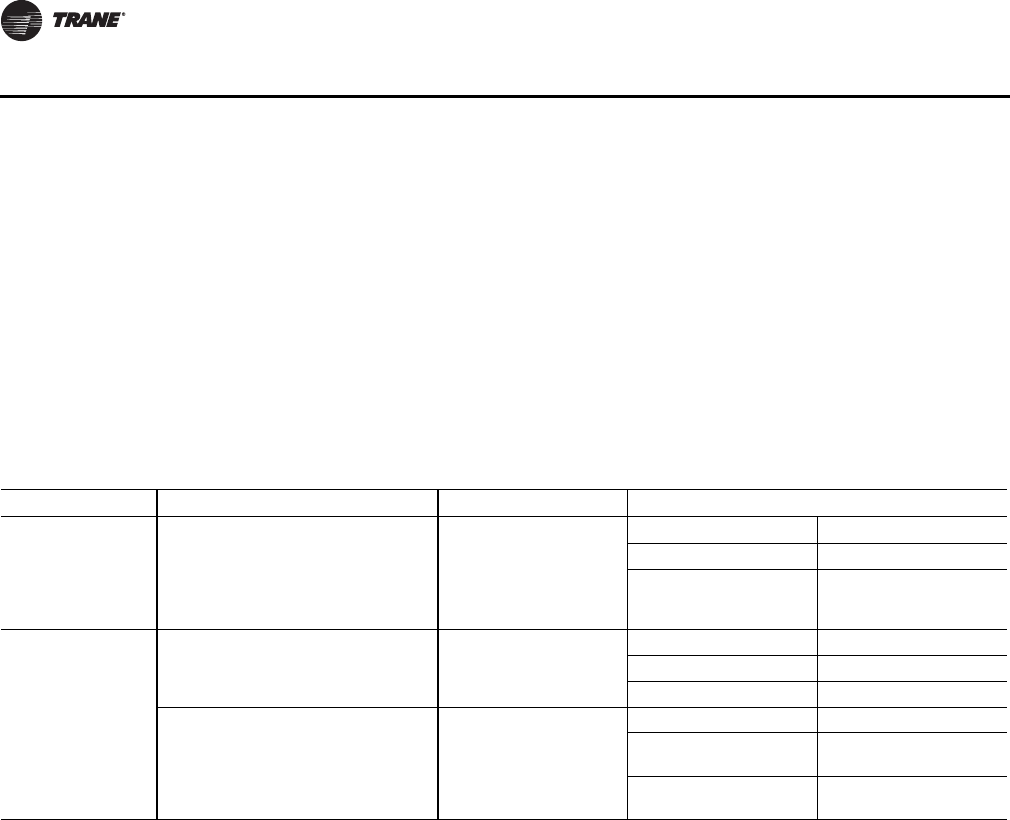
74 VAV-SVP01A-EN
Sequence of Operations
Fan Off Delay
There is a 15-second fan OFF delay. When reheat is turned OFF, the controller turns the fan OFF 15
seconds later.
Ventilation Flow Control
Ventilation flow control (VFC) is one of three supported control algorithms. It is applied to a VAV
terminal and used to temper cold outdoor air (OA) that is brought into a building for ventilation
purposes. The tempered air is intended to supply an air-handling unit (AHU), which provides
comfort control to the zones it is serving. The VAV terminal supplies the correct amount of
ventilation air and, when possible, tempers the ventilation air to reduce the load on the air handler.
See Table 13, p. 74 for ventilation flow control output control.
The ventilation flow control process is a constant volume, variable temperature process.
Single duct VAV units with either electric or hot water reheat are used. Fan-powered units are not
used for ventilation flow control.
Ventilation flow control must have an auxiliary temperature sensor that is located and configured
as a discharge air temperature (DAT) sensor. The required range of discharge air temperature
setpoints is 45°F to 70°F (7.22°C to 21.11°C).
Ventilation flow control staged reheat control (electric or hot water) achieves a 30-minute average
discharge air temperature to within ±5°F (±2.78°C) of the discharge air temperature setpoint when
the inlet temperature is within the control range. Ventilation flow control modulating reheat control
(hot water only) achieves a discharge air temperature to within ±5°F (±2.78°C) of the discharge air
temperature setpoint when the inlet temperature is within the control range.
Air Valve Control
Ventilation flow control uses the air valve as a constant volume device. The unit is given a constant
flow setpoint for air valve control (configured ventilation setpoint); the air valve only repositions
itself in response to changes in inlet static pressure. By using pressure independent control for
ventilation purposes, a constant volume of fresh air can be maintained, regardless of small
fluctuations in inlet static pressure. Ventilation flow control unit can use a Ventilation Setpoint from
a BAS system if it is valid. If unit is stand alone the ventilation flow control uses one of the following
two airflow setpoints:
• If no reheat being used, it uses the configured Ventilation Setup Occupied Setpoint;
• If reheat being used, it uses the configured Local Heat Minimum Airflow.
Table 13. Ventilation flow control outputs
Occupancy mode Source temperature Air valve control Reheat control
Occupy standby
bypass Any
Constant volume (if valid,
communicated ventilation
setpoint; if not valid,
configured ventilation
setpoint)
Electric VFC staged reheat control
Staged hot water VFC staged reheat control
Modulating hot water
VFC modulating reheat
control (same as STC
capacity control)
Unoccupied
Communicated source temperature (if
valid; if not valid, discharge air
temperature) greater than configured
OA low limit
Closed, 0%
Electric Off
Staged hot water Off
Modulating hot water Off
Communicated source temperature (if
valid; if not valid, discharge air
temperature) less than configured OA
low limit
Closed, 0%
Electric Off
Staged hot water On, 100% freeze
protection
Modulating hot water On, 100% freeze
protection
VAV-SVP01A-EN 75
Sequence of Operations
Staged Reheat Control (Electric and Hot Water)
The heat outputs of the controller are binary. Only discrete levels of discharge air temperature are
possible. Since discrete discharge air temperature levels do not always provide an instantaneous
temperature within the required band, staged reheat controls to a 30-minute average discharge air
temperature. The discharge air temperature setpoint is limited from 20°F to 70°F.
Staged Electric Reheat Control
Units that are equipped with electric reheat should be sized so that the maximum temperature rise
across the heating elements is 40°F to 48°F (22.22°C to 26.67°C); it should never exceed 50°F
(27.78°C) for safety reasons. These values were selected to allow the largest control range without
damage to the heater elements. Figure 14, p. 75 shows the achievable control range for ventilation
flow control staged electric heat.
For staged electric ventilation flow control, the number of installed stages can range from one to
three. Three stages are recommended, since finer control is available with more stages. In cases
where the outdoor air temperature is more than 48°F (26.67°C) below the discharge air temperature
setpoint, the controller cannot provide the requested control performance.
The controller provides no cooling capacity. If the outdoor air temperature (OAT) is above the
discharge air temperature setpoint, the discharge air temperature cannot be controlled and the
discharge air temperature is equal to the OAT.
Staged Hot Water Reheat Control
Units equipped with hot water coils should be sized so the maximum temperature of air leaving
the coil does not exceed 140°F (60°C F). Since only one stage of hot water reheat is available, staged
hot water does not allow tight control of the discharge air temperature. Although the controller
operates in this configuration, it is not recommended.
Staged Reheat Control Algorithm (Integral Only)
An incremental form of the integral PID algorithm computes the desired level of reheat capacity.
The algorithm is run once every 10 seconds.
Modulating Reheat Control (Hot Water Only)
Units equipped with hot water coils should be sized so the maximum temperature of air leaving
the coil does not exceed 140°F (60°C). If hot water reheat is installed, the preferred method of
control is with a modulating valve. The modulating valve enables an instantaneous discharge air
temperature within the dead band of the discharge air temperature setpoint. The reheat capacity
algorithm for modulating hot water discharge air temperature control is the same algorithm used
to control modulating hot water valves for a space temperature controller.
Modulating Reheat Control Algorithm (Proportional-Integral)
An incremental form of the proportional integral algorithm runs once every 10 seconds and
calculates the reheat capacity required to meet the discharge air temperature setpoint. The
required capacity is equal to valve position.
Table 14. Ventilation flow control staged electric heat achievable control rang
Minimum OAT for control DAT Setpoint
Some tempering is possible Achievable control range No Control possible No cooling capacity
DAT setpoint cannot be achieved Maximum ∆ T=50°F (27.78°C)
(Electric heat only) DAT = OAT
Cold OAT temperature range Hot
76 VAV-SVP01A-EN
Sequence of Operations
Freeze Protection (Hot Water Only)
Units with hot water coils installed are susceptible to freezing. It is important to prevent the water
coils from freezing. Freeze protection occurs only when the controller is in the Off state or during
the unoccupied period when the primary air valve is closed and the reheat is disabled. During
occupied operation, the control algorithm indirectly provides freeze protection.
Note: See CNT-SVX17*-EN for details on BAS system control of VV550 controller.
Stand-alone Controller Freeze Protection
Controllers operating without communications do not have the source temperature available to
them. In these cases, the discharge air temperature sensor is assumed to provide a reasonable
representation of the coil temperature at conditions with no airflow if the sensor is close to the coil.
If the discharge air temperature, at no airflow, falls below the configured outdoor air low limit, the
hot water valve is fully opened. The hot water valve remains open until the discharge air
temperature is 10°F (5.56°C) above the configured outdoor air low limit or occupied operation
begins. If the communicated source temperature is invalid and the local discharge air temperature
sensor has failed, freeze protection is active and the water valve is open.
Unoccupied Ventilation Flow Control
The controller closes the air valve. Local electric heat and hot water heat are disabled. The hot water
valves open if needed for freeze protection. The operation of freeze protection for local hot water
heat depends on whether the controller is operating as a network controller or a stand-alone
controller. Table 15, p. 76 shows unoccupied VFC control freeze protection for hot water reheat.
Flow Tracking
Flow Tracking Control Mode
Flow tracking control (FTC) is one of three supported control algorithms. Two VAV VV550
Controllers work together to provide flow tracking control. See Figure 50, p. 77 .The space
temperature controller outputs the airflow (reported airflow). The space temperature controller
airflow output (reported airflow) is bound to the flow tracking controller airflow setpoint input
(communicated airflow setpoint). The flow tracking controller adds the configured airflow tracking
offset (positive or negative) to the airflow setpoint (communicated airflow setpoint) and controls
the airflow to this setpoint. The flow tracking controller does not require a space temperature
sensor or a discharge air temperature sensor. If the calculated airflow setpoint is less than 10% of
the configured nominal airflow and the configured airflow tracking offset is less than zero, the air
valve is closed. If the calculated airflow setpoint is less than 10% of the configured nominal airflow
and the configured airflow tracking offset is greater than or equal to zero, the air valve is positioned
Table 15. Unoccupied VFC control, freeze protection for hot water reheat
Controller operation Air valve position Condition
Hot water valve
position
Networked and valid
communicated source
temperature
Closed no flow Communicated source temperature greater than configured
outdoor air low limit Closed
Communicated source temperature less than or equal to
configured outdoor air low limit, freeze protection active diagnostic
(with 10°F hysteresis)
Open to 100%
Stand-alone, coil
temperature sensed at
discharge air
temperature(a)
Closed no flow Discharge air temperature greater than configured outdoor air low
limit Closed
Discharge air temperature less than or equal to configured outdoor
air low limit, freeze protection active diagnostic (with 10°F
hysteresis)
Open to 100%
(a) Place the discharge temperature sensor in close proximity to the hot water coil discharge. The sensor effectively reports coil temperature when there
is no airflow through the coil. Therefore, the coil can be freeze-protected by the discharge air temperature sensor.

VAV-SVP01A-EN 77
Sequence of Operations
at the configured minimum airflow. The maximum airflow setpoint is limited by the configured
maximum airflow.
Air Valve Control in Flow Tracking Control Operation
The VAV VV550 Controllers support one modulating air valve for heating and cooling operation.
Air delivered to the space is controlled with a three-wire floating-point actuator that modulates the
air valve. The controller positions the modulating air valve to deliver the desired airflow (cooling
or heating capacity). The desired airflow is called the active flow setpoint.
Flow tracking control is provided by two controllers working together: space temperature
controller and flow tracking controller. The space temperature controller outputs the airflow as
reported airflow. The airflow is determined by the airflow setpoint input (communicated airflow
setpoint) of the flow tracking controller. The flow tracking controller adds a configured airflow
tracking offset (positive or negative) to the communicated airflow setpoint and controls its airflow
to this new airflow setpoint.
Reheat Control in Flow Tracking Control Operation
Reheat is not an option on a flow tracking controller.
Unoccupied Flow Tracking Control
In unoccupied control mode, the controller operates the air valve the same as it does in occupied
control mode. The controller enters this mode from a communicated command or from a local
occupancy sensor.
Figure 50. Flow tracking control

78 VAV-SVP01A-EN
Air and Water Balancing
Chapter Overview
This chapter contains information about the following:
• Air Balancing
• Rover Air and Water Balancing Tool
Air Balancing
After the unit has been mounted and all electrical and duct connections have been made, the air
distribution system should be balanced. The proper variable air volume balancing procedures
depend on the type of VAV system used and the options specified on the VariTrane unit. This section
will cover the basic balancing procedures and calibrations needed to balance an air distribution
system using VariTrane units. This section suggests only one balancing procedure. Since there are
many possible air balancing procedures, keep in mind that these procedures are only suggestions.
Note: Before performing these balancing procedures, the calibration command should be
initiated at least 15 minutes prior to the balancing procedure.
System Checkout
• Check the VAV system installation for conformity to design.
• Walk the entire system from air handling equipment to the terminal unit to determine variations
of installation from the plans.
• Check for inadvertent obstructions in the ductwork (such as closed fire dampers).
• Insure that any turning vanes, filters, and dampers (both volume and fire) are installed in the
correct position.
• There should be a 1.5 duct diameter long run of straight ducting into the VAV units inlet.
System Setup
• Set the outside air dampers to their minimum position.
• Start the supply and return air fan(s).
• Before balancing the system, ensure that there is enough CFM for all zones.
1. Drive all VAV boxes MAX.
•Starting with each individual branch duct, open all the VAV units in that branch duct to the
maximum cooling position.
Note: This can be done using Rover and its Air and Water Balance tool program by giving each
VAV VV550 Controller a "Drive Max " command or by rotating the Zone sensor set point knob
to the " * " position, and hold the TOV ON button for two seconds. The damper will remain
at its maximum set point until the zone sensor knob is moved back into the normal operating
range.
2. Read airflow at the most remote unit. In most systems, this will be the VAV unit located furthest
from the fan. This will be the unit in the system that will be critical from an air delivery set point.
If airflow is not adequate, increase the supply fan CFM to achieve adequate airflow.
• If the CFM is at or above design, the system can now be balanced. If the measured CFM is below
design, insure the VariTrane unit is in full cooling position.
• If the air delivery through this VariTrane unit is still below the design requirements, increase the
supply fan CFM to achieve adequate airflow.
Note: To increase supply fan CFM check to make sure VFD/IGV are giving max output. If not at max
output; adjust discharge static setpoint until at max output. If already at max output then

VAV-SVP01A-EN 79
Air and Water Balancing
make the required adjustments to pulley sizes, motor sizes and electrical connections to
accommodate fan speed changes. If any adjustment have been made, repeat step 2.
• If after adjusting the fan to its maximum capacity there is still a shortage of airflow, shut off part
of the system to provide enough airflow to balance the other part of the system. This can be
done using Rover or the "Override to Unoccupied" command ("**") at the zone sensor.
3. After determining that there is enough CFM for all zones, drive all the VAV boxes to MIN.
Note: If the VAV boxes have already been assigned to groups and these groups are separate
thermal zones, then the balancing can be done on a group basis.
VAV Single Duct Unit Air Balancing
Select a group to balance and give the VAV units a recalibrate command and then the group a flow
override Drive MAX command.
Note: If the VAV boxes have not been placed in a group, each individual VAV VV550 Controller can
be overridden to Drive MAX in the Override menu in Rover. However, this will be more time
consuming.
Rover Air and Water Balancing Tool
The Rover Air and Water Balancing tool assists with air and water balancing by automating
overrides, calculations, and calibration. The Air and Water Balancing tool supports VAV VV550
Controllers and other controllers that use the LonMark Space Comfort Controller (SCC) profile.
Note: For step-by-step instructions for using this tool, refer to the Air and Water Balancing Tool
Operations guide.
You must connect your computer to a Comm5 link to communicate with the equipment on the link.
You can, however, view job information and reports offline. Refer to the Rover installation sheet for
instructions on connecting to a Comm5 link.
Important: The Air and Water Balancing tool works only with controllers that support the SCC
profile. In addition, the controllers must support the network variables for airflow.
If the Start Air Balancing button is not available on the Equipment tab, the controller
is not compatible with this tool.
Welcome & Selection Screen
When Rover launches, click the Air and Water Balancing Tool button to launch the selection screen.
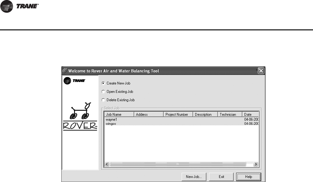
80 VAV-SVP01A-EN
Air and Water Balancing
Create New Job
Click this option, then click the Create New Job button to create a new job.
Open Existing Job
Click this option, select a job from the list, then click the Open Job button to open an existing job.
Delete Existing Job
Click this option, select a job from the list, then click the Delete Job button to delete a job.
Select Job to Open
Shows a list of existing jobs. Use this list to select an existing job to open or delete.
Create New Job / Open Job / Delete Job button
This button changes depending on the option you select at the top of the screen. After selecting
an option, click this button to perform the task.
Exit button
Click Exit to close the Air and Water Balancing tool.
Figure 51. Balancing tool screen
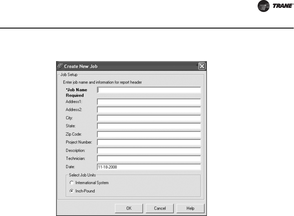
VAV-SVP01A-EN 81
Air and Water Balancing
Job tab
Use this tab to modify the open job.
Note: A "job" contains all the controllers on a single Comm5 link. You can open only one job at
a time. If you have more than one Comm5 link at a site, use different job names for each link.
Job Name
The name of the currently open job. You cannot change this name on the Job tab.
Address 1 and 2
Type the street address of the job.
City
Type the name of the city where the job is located.
State
Type the name of the state or province.
Zip Code
Type the postal zip code.
Project Number
Type the project number for the job.
Description
Type of description of the job or Comm5 link.
Figure 52. Create new job screen

82 VAV-SVP01A-EN
Air and Water Balancing
Technician
Type the name of the technician performing the air and water balancing.
Date
The default value is the date on which the job was created in the Air and Water Balancing tool. You
can change this to a different date.
Select Job Units
Click Inch-Pound to use cubic feet per minute (cfm) to measure airflow. Click International System
to use SI units, such as liters per second (L/s) to measure airflow. The units you select are used only
for reporting purposes in the Air and Water Balancing tool-they do not affect the units used in the
controller or in Rover Comm5.
Change Airflow Units button
This button appears only if you select to use SI units. Click this button to select one of the following
SI units of measurement:
• Liters per second (L/s)
• Cubic meters per second (m3/s)
• Cubic meters per minute (m3/min.)
Airflow Units
The selected SI units of measurement for airflow. This field appears only when SI units are selected.
Save button
Click this button to save any changes you have made to the job information.
Create Report button
Click this button to create a balancing report.
Open Another Job button
Click this button to open another job.
Exit button
Click this button to close the Air and Water Balancing tool.

VAV-SVP01A-EN 83
Troubleshooting
WARNING
Live Electrical Components!
During installation, testing, servicing and troubleshooting of this product, it may be necessary
to work with live electrical components. Have a qualified licensed electrician or other individual
who has been properly trained in handling live electrical components perform these tasks.
Failure to follow all electrical safety precautions when exposed to live electrical components
could result in death or serious injury.
Chapter Overview
This chapter contains information about the following:
• Diagnosing the Problem
•Diagnostic Log
•Diagnostic Table
•LED Operation
• Troubleshooting Procedures
•VV550 Failure Procedures
•VV550 Communication Loss Procedures
•Wired Zone Sensor Failure Procedures
•Wired Zone Setpoint Failure Procedures
•Wireless Zone Sensor Failure Procedures
•Airflow Failure Procedures
•Duct Temperature Sensor Failure Procedures
•VAV Damper Failure Procedures
•VAV Series Fan Failure Procedures
•VAV Parallel Fan Failure Procedures
•VAV Electric Heat Stage(s) Failure Procedures
•VAV Proportional Hot Water Failure Procedures
•Trane/Honeywell Proportional Valve Check Out Procedure
•VAV Two Position Hot Water Failure Procedures
Diagnosing the Problem
Green Status LED will give you an indication if a diagnostic is present. If diagnostic is present, use
Rover Service tool or Tracer Summit to access VV550 diagnostics. See Table 16, p. 85 for
diagnostics. After diagnostics have been assessed, find correct procedures for troubleshooting
issue.
Note: VV550 binary outputs can be exercised by Rover Service tool. See status and programming
sections for detail
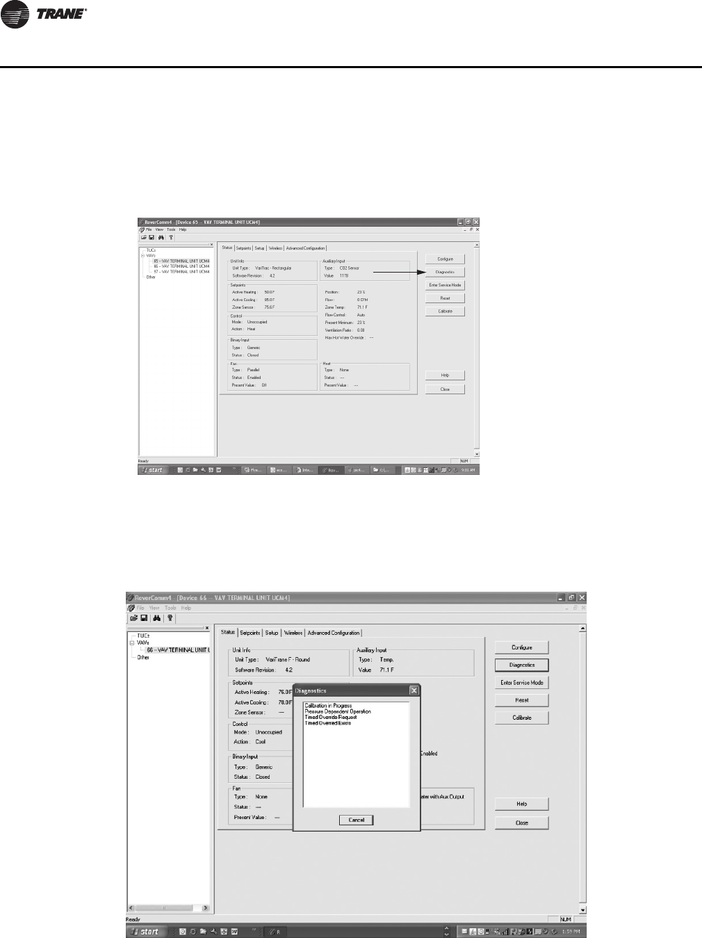
84 VAV-SVP01A-EN
Troubleshooting
Diagnostic Log
The Diagnostic Log reports diagnostic and informational modes/items that are not in the unit's
normal operation.
Some of the items reported are listed to aid in understanding current operation. Reported items are:
1) Timed Override Exists, 2) Cancel Timed Override, 3) Auxiliary Temperature Sensor Not Present,
4) Unoccupied Request from Zone Sensor ** Function, 5) Max Flow Request from Zone Sensor *
Function, 6) Calibration in Progress, and 7) Pressure Dependent Operation.
Figure 53. Diagnostic log
Figure 54. Items reported
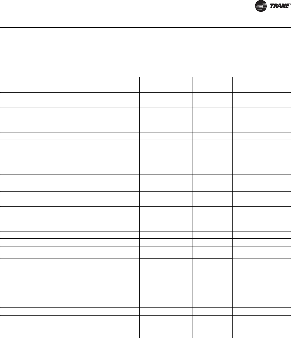
VAV-SVP01A-EN 85
Troubleshooting
Diagnostic Table
Ta ble 16 , p . 85 shows the VAV VV550/551 Controller diagnostics.
Table 16. Controller diagnostics
Diagnostic Air valve Fan Reheat
Invalid unit configuration(a) 0 VDC 0 VDC 0 VDC
Controller failure Closed Off Off
Discharge air temperature failure (space temperature control) Normal Normal Normal
Discharge air temperature failure (ventilation flow control without
reheat)
Normal Don't care Don't care
Discharge air temperature failure (ventilation flow control with
reheat)
Closed Don't care Off
Discharge air temperature failure (flow tracking control) Normal Don't care Don't care
Low airflow (space temperature control) Normal Normal Local electric heat is Off;
local hydronic and all remote
heat is normal
Low airflow (ventilation flow control) Normal Don't care Local electric heat is Off;
local hydronic is normal;
remote is Don't care
Primary air temperature failure (space temperature control) Normal Normal Local electric heat is Off(b);
local hydronic and all remote
heat is normal
Primary air temperature failure (ventilation flow control) Normal Don't care Normal
Primary air temperature failure (flow tracking control) Normal Don't care Don't care
Space temperature fail (space temperature control)(c) Occupied: cool minimum
flow setpoint Unoccupied:
closed
Series fan enabled;
parallel fan Off
Off
Space temperature fail (ventilation flow control)(c) Normal Don't care Normal
Space temperature fail (flow tracking control)(c) Normal Don't care Don't care
Local setpoint failure Normal Normal Normal
Flow sensor failure or flow sensor calibration failure (space
temperature control)
Normal pressure
dependent control
Normal Normal
Flow sensor failure or flow sensor calibration failure (ventilation flow
control)
Normal pressure
dependent control
Don't care Normal
Flow sensor failure or flow sensor calibration failure (flow tracking
control)
If the configured airflow
tracking offset is positive,
configure maximum
airflow. If the configured
airflow tracking offset is
negative, configure
minimum airflow
Don't care Don't care
Freeze protection active (ventilation flow control) Closed Off Off
Thumbwheel in */** position (single star position) Minimum airflow Normal Normal
Thumbwheel in */** position (double star position) Maximum airflow Normal Normal
Normal Normal Normal Normal
(a) When the unit configuration is invalid, all outputs are de-energized (0 VDC) so that they return to their normal state.
(b) If system mode is heat or auto with a warm or hot primary air temperature.
(c) When a temperature sensor fails after being valid, the controller generates a diagnostic to indicate the sensor loss condition. The controller automatically
clears the diagnostic once a valid sensor temperature value is present (non-latching diagnostic).
86 VAV-SVP01A-EN
Troubleshooting
Resetting Diagnostics
A reset clears latching diagnostics and enables the controller to try to run normally. If the latching
condition is still present after the reset, the controller shuts down. A reset resets a unit that is
running normally. There are five ways to reset unit diagnostics:
• Manual output test at the controller
• Cycling power to the controller
• BAS (communicated status request, clear alarm)
• Rover service tool (communicated status request, clear alarm)
• A communicating device able to access the controller diagnostic reset input (communicated
status request, clear alarm)
LED Operation
Red Service LED
Service Push Button
Important: If the Service button is held down for more than 15 seconds, the controller will
uninstall itself from the Comm5 network. The red service LED flashing
approximately once every two seconds indicates this mode (see Red service LED
above). Use the Rover service tool to restore the unit to normal operation. Refer the
Rover product literature for more information.
The Service push button can be used, as one of several methods, to install the controller in a
communication network. Refer to the Rover service tool product literature for more information.
Green Status LED
The green status LED is typically used to indicate whether or not the controller is powered On
(24VAC). This is the only LED under direct software control. The green status LED is Off when you
press the Test button. The green status LED blinks during manual output testing. Table 18, p. 87
shows and describes the green status LED activity.
Ta b l e 1 7. Red service LED activity
Red Service LED Activity Description
LED is Off continuously after power is applied to the
controller.
Normal operation
LED is On continuously, even when power is first applied to
the controller.
Someone is pressing the Service push button or the
controller failed.
LED flashes approximately once every two seconds. Uninstalled (normal controller mode). Use the Rover™
service tool to restore the unit to normal operation. Refer
to the Rover product literature for more information.
VAV-SVP01A-EN 87
Troubleshooting
Troubleshooting Procedures
VV550 Failure Procedures
WARNING
Live Electrical Components!
During installation, testing, servicing and troubleshooting of this product, it may be necessary
to work with live electrical components. Have a qualified licensed electrician or other individual
who has been properly trained in handling live electrical components perform these tasks.
Failure to follow all electrical safety precautions when exposed to live electrical components
could result in death or serious injury.
1. Incorrect supply voltage/No voltage
•Check Green Status LED.
•Shows solid green when the VV550 is powered and operating normally.
•If Green Status LED is off, check incoming power. Measure the power input to VV550 board
on TB1-1 24VAC input and ground TB1-2. The supply voltage should be between 19 and 30
VAC (24VAC cataloged). However, voltages at either extreme may result in system
instability.
•If no voltage, check up stream of controller to see were voltage has been interrupted. See
complete wiring diagrams, Figure 59, p. 107 to Figure 66, p. 114.
2. Check for short
•Remove all wires from controller except incoming power.
•Check device using Rover service tool to see if the VAV VV550 is operating properly. If VV550
does operate properly check inputs/outputs for a short.
3. For final step check program by downloading good program using Rover Service tool. See the
Saving VAV Program-portion of the VAV VV550 Controller Programming and Operation section.
Note: For Instructions on how to use Rover, refer to the Rover Help by clicking on Rover Help
in the Help menu.
4. If controller is still failed, replace controller.
Ta b l e 1 8 . Green status LED activity
Green Status LED Activity Description
On Power On, normal operation
Off One of the following:
•Power Off
• Controller failure
• Test button pressed
Blinking for 10 seconds,
0.25 seconds Off; 0.25 seconds On
Wink mode(a)
(a) The wink feature enables you to identify a controller. By sending a request from the Rover™ service tool, you can request
the controller to wink.
One blink continuously,
0.25 seconds Off; 2.25 seconds On
The controller is in the manual output test mode and no
output-override unit diagnostic(b) conditions
(b) See the diagnostic topic in this guide for a complete list of output override diagnostics.
Two blinks continuously,
0.25 seconds Off; 0.25 seconds On
0.25 seconds Off; 1.75 seconds On
The controller is in the manual output test mode and one
or more output-override unit diagnostic(b) conditions exist

88 VAV-SVP01A-EN
Troubleshooting
VV550 Communication Loss Procedures
In the event that the VV550 is not communicating properly (No activity on Communication LED's)
inspect the following:
WARNING
Live Electrical Components!
During installation, testing, servicing and troubleshooting of this product, it may be necessary
to work with live electrical components. Have a qualified licensed electrician or other individual
who has been properly trained in handling live electrical components perform these tasks.
Failure to follow all electrical safety precautions when exposed to live electrical components
could result in death or serious injury.
1. Incorrect supply voltage/No voltage
•Check Green Status LED.
•Shows solid green when the VV550 is powered and operating normally.
•If Green Status LED is off, check incoming power. Measure the power input to VV550 board
on TB1-1 24VAC input and ground TB1-2.
The supply voltage should be between 19 and 30 VAC (24VAC cataloged). However, voltages
at either extreme may result in system instability.
•If no voltage, check up stream of controller to see were voltage has been interrupted. See
complete wiring diagrams, Figure 59, p. 107 to Figure 66, p. 114.
2. Communication link signal has interference
•Communication link should not be routed near or with any voltage source.
3. Incorrect wire used
•Recommended wire is twisted shielded pair. See VAV Startup/Check out Procedure chapter
for the wiring specifications for VV550
•Check device using Rover service tool to see if VV550 is operating properly. If VV550 does
operate properly, check inputs/outputs for a short.
4. For final step check program by downloading good program using Rover Service tool. See the
Saving VAV Program-portion of the VAV VV550 Controller Programming and Operation chapter.
Note: If still not communicating to Rover service tool and communication link, replace controller.
Communication Failure
LINK
• The TX LED blinks green at the data transfer rate when the VV550 transfers data to other devices
on the link.
• The RX LED blinks yellow at the data transfer rate when the VV550 receives data from other
devices on the link.
Wiring Best Practices
Note: See start up and check out procedures for best wiring practices.

VAV-SVP01A-EN 89
Troubleshooting
Wired Zone Sensor Failure Procedures
WARNING
Hazardous Service Procedures!
The maintenance and troubleshooting procedures recommended in this section of the manual
could result in exposure to electrical, mechanical or other potential safety hazards. When
possible, disconnect all electrical power including remote disconnect and discharge all energy
storing devices such as capacitors before servicing. Follow proper lockout/tagout procedures to
ensure the power can not be inadvertently energized. When necessary to work with live
electrical components, have a qualified licensed electrician or other individual who has been
trained in handling live electrical components perform these tasks. Failure to follow all of the
recommended safety warnings provided, could result in death or serious injury.
In the event that the VV550 reports an incorrect zone temperature, properly inspect the following:
1. Actual room temperature is higher or lower than what the VV550 reads
•Check the location and installation of the zone sensor. Change the calibration factor in the
VAV VV550 Controller setup screens.
Note: If Zone sensor is off more than ± 2 degrees continue to number 2.
2. Zone sensor wired incorrectly
•Check wiring for the correct connections. See VAV Startup/Check out Procedure chapter for
the wiring specifications for VV550
3. Defective zone sensor
•Disconnect the zone sensor terminal plug from the VV550 and using an Ohmmeter, measure
the resistance across the terminals 1 and 2. Compare the resistance to temperature using
Table 19, p. 90. The resistance should shown value should be within ± 2 degrees near those
measured with an accurate temperature measuring device. If not, the zone sensor needs to
be replaced.
4. Defective wiring or VV550
•With wires still connected to VAV VV550, disconnect zone sensor wires and check voltage
(DC) from wires that were connected to terminals 1 and 2 of zone sensor. You should
measure 5VDC. If 5VDC not present then see if the VAV VV550 is outputting 5VDC. This can
be done by disconnecting the wires on the VAV VV550 on terminals TB3-1 and TB3-2 and
measure the VDC. It should be 5VDC. If you have 5VDC at the VV550 the wires going to the
zone have an open. If 5VDC is not present check incoming power to the VV550 board on TB1-
1 24VAC input and TB1-2 should measure 24VAC ± 10%. If you measure the proper voltage
at on TB1-1 24VAC input and TB1-2 and no voltage at TB3-1 and TB3-2 replace VV550.
5. Zone sensors shorted out
•Check the resistance across the wires. Disconnect wires from VV550 and zone sensor making
sure the ends are not touching each other and measure resistance. It should be infinity or
no conductivity. If lower resistance is shown wires are shorted together and needs to be
replaced.
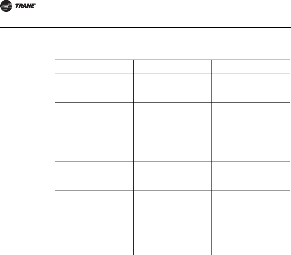
90 VAV-SVP01A-EN
Troubleshooting
Wired Zone Setpoint Failure Procedures
WARNING
Hazardous Service Procedures!
The maintenance and troubleshooting procedures recommended in this section of the manual
could result in exposure to electrical, mechanical or other potential safety hazards. When
possible, disconnect all electrical power including remote disconnect and discharge all energy
storing devices such as capacitors before servicing. Follow proper lockout/tagout procedures to
ensure the power can not be inadvertently energized. When necessary to work with live
electrical components, have a qualified licensed electrician or other individual who has been
trained in handling live electrical components perform these tasks. Failure to follow all of the
recommended safety warnings provided, could result in death or serious injury.
In the event that the VV550 reports an incorrect zone setpoint, properly inspect the following:
1. Zone sensor setpoint wired incorrectly
•Check wiring for the correct connections.
2. Defective zone sensor setpoint dial
Table 19. Zone sensor temperature resistance
Temp (oF) Thermostat Thumbwheel
Resistance (Ohms)
Sensor Resistance (k Ohms)
55
56
57
58
59
792
772
753
733
714
17.0
16.5
16.1
15.7
15.4
60
61
62
63
64
694
675
656
636
617
15.0
14.6
14.3
14.0
13.6
65
66
67
68
69
597
578
558
539
519
13.3
13.0
12.6
12.3
12.1
70
71
72
73
74
500
481
461
442
422
11.8
11.5
11.2
11.0
10.7
75
76
77
78
79
403
383
364
344
325
10.4
10.2
10.0
9.7
9.5
80
81
82
83
84
85
306
286
267
247
228
208
9.3
9.0
8.8
8.6
8.4
8.2
Note: Thumbwheel resistance checks are made at terminal 2 and 3 on the zone sensor. Temperature sensor resistance is
measured at terminal 1 and 2 of the zone sensor.

VAV-SVP01A-EN 91
Troubleshooting
•Disconnect the zone sensor terminal plug from the VV550 and using an Ohmmeter, measure
the resistance across the terminals 2 (common) and 3 (setpoint). Compare the resistance to
specified set point on sensor using Tab l e 19, p. 9 0. The resistance shown should correlate
within ± 2 degrees of setpoint shown on Table 19, p. 90 If not, the zone sensor needs to be
replaced.
3. Defective wiring or VV550
•With wires still connected to VAV VV550, disconnect zone sensor setpoint wires and check
voltage (DC) from wires that were connected to terminals 2 and 3 of zone sensor. You should
measure 5VDC. If you do not have 5VDC then see if the VAV VV550 is outputting 5VDC. This
can be done by disconnecting the wires on the VAV VV50 on terminals TB3-2 and TB3-3 and
measure the VDC. It should be 5VDC. If you have 5VDC at the VV550 the wires going to the
zone have an open. If 5VDC is not present check incoming power to the VV550 board on TB1-
1 24VAC input and TB1-2. Voltage should measure 24VAC ± 10%. If you measure the proper
voltage at on TB1-1 24VAC input and TB1-2 and no voltage at TB3-2 and TB3-3 replace VV550.
4. Zone sensor setpoint is shorted out
•Check the resistance across the wires. Disconnect wires from VV550 and zone sensor making
sure the ends are not touching each other and measure resistance. It should be infinity or
no conductivity. If lower resistance is shown wires are shorted together and needs to be
replaced.
Wireless Zone Sensor Failure Procedures
In the event that the VV550 reports an incorrect zone Temperature/setpoint, properly inspect the
following:
Note: No special tools or software are necessary to service and test the wireless zone sensor
system. The system can be testing by using the following: 1) LEDs 1, 2, 3, and 5 on the sensor
and on the receiver; 2) The Test button (S5) on the sensor; 3) The address test mode on the
receiver; and 4) A common volt-ohm meter.
Diagnostics
Note: Reading diagnostics can show if the sensor has an issue or it has not been setup properly.
Use this information as a starting point
• LED1, LED2, and LED3 will respond to diagnostics by exhibiting specific blinking patterns. They
will occur on the sensor as a result of pressing the Test button (S5) (Table 23, p. 93). They will
occur on the receiver independently of any user action (Table 23, p. 93).
Figure 55. Wireless sensor set components with base plates removed
LED 1
LED 2
LED 3
LED 5
LED 1
LED 2
LED 3
LED 5
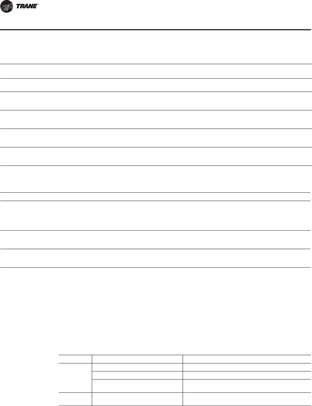
92 VAV-SVP01A-EN
Troubleshooting
1. wireless zone sensor system failure.
•Observe LED5 on the receiver. LED5 will be On solid green whenever the receiver is
powered.
•Make sure the receiver is properly grounded. Both the black wire (GND SIGNAL) and the
yellow wire (GND-POWER) must be grounded.
•Press the Test button (S5) on the sensor. Models WTS, WZS LED5 should turn On solid green,
indicating proper battery strength. LED1, LED2, and LED3 will indicate signal strength (See
Table 23, p. 93).
Table 20. Diagnostics on the sensor
LED state when Test button is pressed
(WTS, WZS sensors)
Error code (WDS
sensor display) Indicates…
N/A E0, E5, E7 Sensor failure
- Replace sensor
LED1: Off
LED2: Off
LED3(a): 1-blink pattern repeated 3 times
E1 Disassociated
- Sensor is not associated with a receiver
LED1: Off
LED2: Off
LED3(a): 2-blink pattern repeated 3 times
E2 Address set to 000
- Address not set to between 001-999
LED1: Off
LED2: Off
LED3(a): 3-blink pattern repeated 3 times
E3 Software error
- Replace sensor
LED1: Off
LED2: Off
LED3(a): 4-blink pattern repeated 3 times
E4
Input voltage too high
- No RF transmission is permitted with an input battery voltage
greater than 3.9V
(a) Blink pattern is On for 1/4s, Off for 1/4s, with 2s OPff between repetitions.
Table 21. Diagnostics on the receiver
LED state Indicates…
LED1: Off
LED2: Off
LED3: 1-blink pattern repeated continuously(a)
Disassociated
* Receiver is not associated, waiting for a sensor
* Receiver lost communication with sensor
* Receiver has no devices on its wireless personal area network
* Association with a device has been manually removed
LED1: Off
LED2: Off
LED3: 2-blink pattern repeated continuously(a)
Address set to 000
* Address not set to between 001-999
LED1: Off
LED2: Off
LED3: 3-blink pattern repeated continuously(a)
Not configured
* Receiver configuration properties bot properly set (defective
receiver)
(a) Blink pattern is On for 1/4 s, Off for 1/4 s, with 2 s Off between repetitions.
Table 22. Battery status: LED5 on the sensor
User Action LED Display Indicates…
Press Test
Button (SS)
Solid green for 5 seconds Battery condition is adequate for proper operation.
Solid red for 5 seconds Battery condition is low. Batteries should be replaced.
No light Batteries are totally dead or not installed properly, or sensor
is defective.
None Blinking red: 1-blink pattern1 repeated 5
times. Cycle repeats every 15 minutes.
Battery condition is low. Approximately 14 days of operation
remain before the battery is too weak to power the sensor.
Note: 1 Blink pattern is On for ¼ s, Off for 3/4 s, with 2 s Off between repetitions.
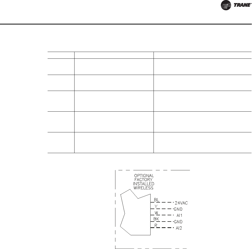
VAV-SVP01A-EN 93
Troubleshooting
Note: When checking signal strength, both LED1 and LED3 on the receiver and sensor should
illuminate in unison if the sensor and receiver are associated. Use this feature to confirm
association. If not associated, see setup procedures in Wireless chapter. If unit still does not
work proceed in checking Receiver and sensor with testing procedures below.
2. Procedure for Testing the Receiver
•Make sure the receiver is powered.
•Set the receiver address to 000 to force the zone temperature output and zone temperature
setpoint output to their test mode values (see Table 24, p. 94).
Table 23. Signal quality: LED1, LED2, LED3 on the sensor
User Action LED Display Indicates…
None
LED1:Off
LED2:Off
LED3:Off
Normal state
* No Test button press
Press Test
Button (SS)
LED1:Off
LED2:Off
LED3:Off
Associated; no communication with receiver
* Associated, but no signal from the receiver after
pressing Test button
Press Test
Button (SS)
LED1:On
LED2:On
LED3:On
Displays for 5 seconds, then constantly off
Excellence signal quality
* Adequate signal margin for reliable communication.
Press Test
Button (SS)
LED1:Off
LED2:On
LED3:On
Displays for 5 seconds, then constantly off
Marginal signal quality
* Reduced battery life likely.
* Consider moving the sensor or receiver to a better
location.
Press Test
Button (SS)
LED1:Off
LED2:Off
LED3:On
Displays for 5 seconds, then constantly off
Poor signal quality
* Unreliable communication.
* Strongly recommend moving the sensor or receiver to
a better location.
Figure 56. Receiver wiring connections
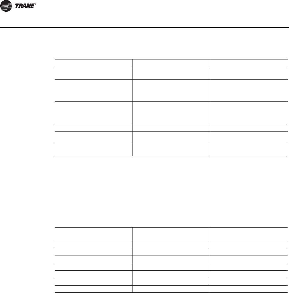
94 VAV-SVP01A-EN
Troubleshooting
3. Measure the receiver output resistance by following the procedures
•Make sure the black wire (GNS-SIGNAL) and the yellow wire (GND-POWER) are grounded
(see above for wiring diagrams).
•Make sure the receiver is powered up.
•Disconnect the SETPOINT wire (red) and the ZONE wire (white) from the host unit controller.
•Measure resistance between the grounded GND-SIGNAL wire and either the SETPOINT or
ZONE wire. Compare resistance measurements to those presented in Table 25, p. 94.
•When the test is complete, reset the receiver address to its previous setting.
•Press the Test button (S5) on the sensor to force re-association.
Confirm association and communication by noting LED1, LED2, and LED3 as described in "Signal
Quality Test"
•Pressing the Test button (S5) on the sensor initiates a signal quality test. LED1, LED2, and
LED3 respond by indicating excellent, marginal, or poor signal quality. The LEDs can be
observed on both the sensor (Table 26, p. 95) and the receiver (Ta b l e 2 7, p . 9 5 ).
Table 24. Output failure modes of operation
Situation Zone Temperature Output Zone Setpoint Output
Receiver address = 000 11.17 kΩ, 72.5 oF (22.5 oC),
indefinitely 451 Ω, 72.5 oF (22.5 oC), indefinitely
Receiver address = 001 to 999
Receiver has powered up, but has not
received a communication from
sensor.
11.17 kΩ, 72.5 oF (22.5 oC) 451 Ω, 72.5 oF (22.5 oC)
Receiver address = 001 to 999
Receiver does not receive a
communication within 35 minutes
from the sensor it is associated with
Open Open
Receiver has no power Open Open
Thermistor in sensor has failed to
either open or close Open Normal value
Setpoint potentiometer has failed to
either open or close Normal value Open
Table 25. Receiver resistance
Zone or Setpoint Temperature
Nominal Zone Temperature
Output Resistance
Nominal Space Temperature
Setpoint Output Resistance
55 oF (12.8 oC) 17.47 k Ω812 Ω
60 oF (15.6 oC) 15.3 k Ω695 Ω
65 oF (18.3 oC) 13.49 k Ω597 Ω
70 oF (21.1 oC) 11.9 k Ω500 Ω
75 oF (23.9 oC) 10.5 k Ω403 Ω
80 oF (26.7 oC) 9.3 k Ω305 Ω
85 oF (29.4 oC) 8.25 k Ω208 Ω
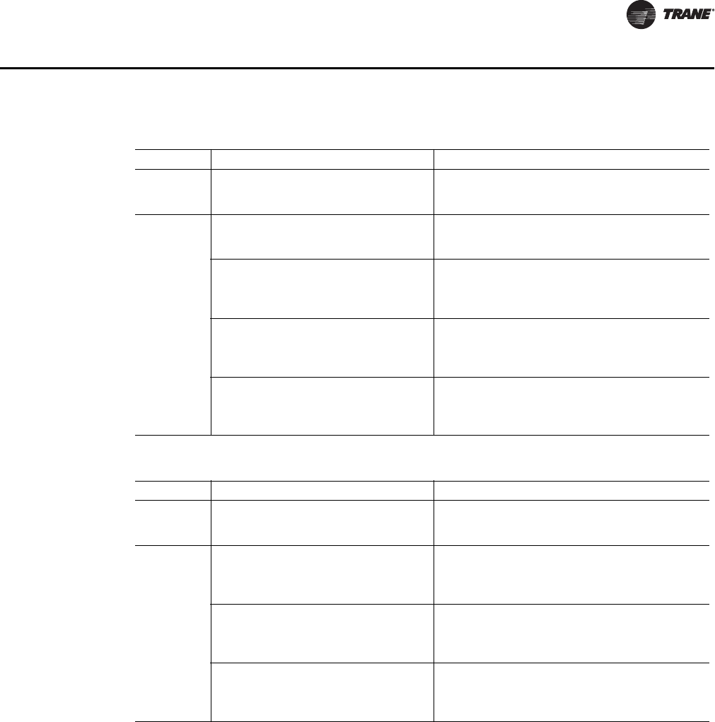
VAV-SVP01A-EN 95
Troubleshooting
•If sensor and receiver still do not operate properly, replace bad components. If unit passes
tests, check VV550 operation.
4. Defective VAV VV550
•Disconnect the receiver sensor wires on the VAV VV550 on terminals TB3-1 and TB3-2 and
measure the VDC. It should be 5VDC. If 5VDC is not present check incoming power to the VAV
VV550 Controller board on TB1-1 and TB1-2. Should measure 24VAC ± 10%. If you measure
the proper voltage at TB1-1 and TB1-2 and no voltage at TB3-1and TB3-2 replace VV550.
Note: If no voltage at TB1-1 and TB1-2, see VV550 failure procedures
•Disconnect the receiver sepoint wires on the VAV VV550 on terminals TB3-2 and TB3-3 and
measure the VDC. It should be 5VDC. If 5VDC is not present check incoming power to the VAV
VV550 Controller board on TB1-1 and TB1-2. Should measure 24VAC ± 10%. If you measure
the proper voltage at TB1-1 and TB1-2 and no voltage at TB3-2and TB3-3 replace VV550.
Table 26. Signal quality: LED1, LED2, LED3 on the sensor
User Action LED Display Indicates…
None LED1:Off
LED2:Off
LED3:Off
Normal state
* No Test button press
Press Test
Button (SS)
LED1:Off
LED2:Off
LED3:Off
Associated; no communication with receiver
* Associated, but no signal from the receiver after
pressing Test button
LED1:On
LED2:On
LED3:On
Displays for 5 seconds, then constantly off
Excellence signal quality
* Adequate signal margin for reliable communication.
LED1:Off
LED2:On
LED3:On
Displays for 5 seconds, then constantly off
Marginal signal quality
* Reduced battery life is likely.
* Consider moving the sensor or receiver to a better
location.
LED1:Off
LED2:Off
LED3:On
Displays for 5 seconds, then constantly off
Poor signal quality
* Unreliable communication.
* Strongly recommend moving the sensor or receiver to
a better location.
Table 27. Signal quality: LED1, LED2, LED3 on the receiver
User Action LED Display Indicates…
None LED1:Off
LED2:Off
LED3:Off
Normal state
* No Test button press
Press Test
Button (SS)
LED1:On
LED2:On
LED3:On
Displays for 5 seconds, then constantly off
Excellence signal quality
* Adequate signal margin for reliable communication.
LED1:Off
LED2:On
LED3:On
Displays for 5 seconds, then constantly off
Marginal signal quality
* Reduced battery life is likely.
* Consider moving the sensor or receiver to a better
location.
LED1:Off
LED2:Off
LED3:On
Displays for 5 seconds, then constantly off
Poor signal quality
* Unreliable communication.
* Strongly recommend moving the sensor or receiver to
a better location.

96 VAV-SVP01A-EN
Troubleshooting
Airflow Failure Procedures
WARNING
Hazardous Service Procedures!
The maintenance and troubleshooting procedures recommended in this section of the manual
could result in exposure to electrical, mechanical or other potential safety hazards. When
possible, disconnect all electrical power including remote disconnect and discharge all energy
storing devices such as capacitors before servicing. Follow proper lockout/tagout procedures to
ensure the power can not be inadvertently energized. When necessary to work with live
electrical components, have a qualified licensed electrician or other individual who has been
trained in handling live electrical components perform these tasks. Failure to follow all of the
recommended safety warnings provided, could result in death or serious injury.
In the event that the air valve is reading position instead of flow or in the event that the measured
flow reads incorrectly, i.e. different from the balance report, properly inspect the following:
• Recalibrate VAV unit by cycling power to unit. This can also be accomplished with Rover service
tool or Tracer Summit. To Calibrate:
Note: Cycling power to the VAV board will automatically cause the unit to calibrate, however,
following the procedure outlined below will provide a more accurate calibration. It is
only necessary to perform this procedure in instances where you are experiencing
incorrect flow readings or if the unit reverts to pressure dependent mode despite being
above 5% and below 110% of cataloged flow and performing a "normal calibration") and
does not correct the problem.
1. Steps for Calibration
•Log on to the VAV VV550 Controller with Rover software.
•Turn the central air handler "off." If this is not possible, Trane recommends pulling the
transducer tubes off during the calibration process to simulate this.
•Select the "calibrate unit" option button.
•Rover software will indicate that calibration is taking place in the diagnostic log.
•When calibration is complete, the box will release to auto. Drive the box open to make sure
that the box is not below 5% of its cataloged CFM. The controller is accurate in reading flow
from 5% to 110% of cataloged CFM.
•Release the box to auto and perform any necessary balancing work. See Rover Help for
balancing details.
•Check to see if flow has been established, If flow not established or inaccurate proceed
to Step 2.
2. The tubing or flow ring is off, reversed, plugged, or has a leak.
•Check with a magnehelic gauge and compare with the delta pressure (DP) chart located on
the VAV box.
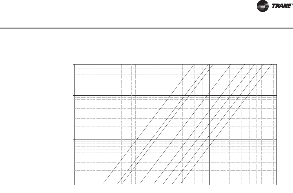
VAV-SVP01A-EN 97
Troubleshooting
•Check the tubing for reversal and/or leaks.
•Check the flow ring for plugged holes. Blow out with compressed air if necessary.
3. Wrong unit size downloaded into the VAV VV550 Controller setup menu
•Verify that the actual unit size matches the unit's nameplate.
4. Poor inlet configuration
•Trane recommends 1½-duct diameters of straight duct before the inlet of the box (a 12-inch
box should have 18 inches of straight run duct before the inlet).
5. To determine whether or not the transducer has failed, perform the following steps:
•Check the 24 volts AC supply at TB1-1 24VAC input and TB1-2 on the VAV VV550 Controller
board. Voltage should be between 20 volts AC and 28 volts AC.
•Read the input voltage to the transducer from the VAV VV550 Controller between the green
and red wires on P1 of the VAV VV550 Controller board. The voltage should be between 4.50
volts DC and 5.50 volts DC (5 volts DC cataloged). If no voltage indicated, replace the VAV
VV550 Controller.
•Remove the high and low tubes from the transducer (to simulate no flow). Read the
transducer output voltage on P1 of the VAV VV550 Controller board between the green and
the black wires with a voltmeter. The voltage should be between 0.20 volts DC and 0.30 volts
DC (0.25 volts DC is the null voltage output of the transducer indicating zero flow). If voltage
not available replace transducer
Note: The formula for the Transducer output voltage is 0.25 + 0.75 * <delta P>, where delta P
is the pressure in inches of water column. Delta P can range from 0 to 5 inches of W.C.
•With flow going across the flow ring measure the differential pressure with a magnahelic
and use Transducer output voltage formula to check accuracy of reported value. Read the
transducer output voltage between the green and the black wires. The measured value
should correspond to the value given in the transducer output formula. If transducer is off
by ± 5%, replace transducer.
Figure 57. Sensor signal vs. airflow delivery
0.01
0.1
1
5
10 100 1,000 10,000
Cfm
Flow Sensor DP (In . w g )
4" 12"10"8"6"
5" 14"16"

98 VAV-SVP01A-EN
Troubleshooting
Duct Temperature Sensor Failure Procedures
In the event that the VV550 reports an incorrect or failed Discharge or Primary air temperature,
properly inspect the following:
1. Make sure VAV VV550 has been configured for the input
2. Discharge or Primary air temperature is higher or lower than what the VV550 reads
•Check the location and installation of the sensor. Change the calibration factor in the VV550
setup screens.
Note: If sensor is off more than ± 2 degrees continue to number 3.
3. Auxiliary sensor wired incorrectly
•Check wiring for the correct connections. See Chapter 2 for further details on Discharge or
Primary air sensor wiring.
4. Defective sensor
•Disconnect the sensor terminal plug from the VV550 and using an Ohmmeter, measure the
resistance across the auxiliary sensor wires. Compare the resistance to temperature using
Table 11, p. 72. The resistance measured should correspond to a temperature within ± 2
degrees near those measured with an accurate temperature measuring device. If not, the
sensor needs to be replaced.
5. Defective wiring or VV550
•See if the VAV VV550 Controller is outputting 5VDC. This can be done by disconnecting the
wires on the VAV VV550 Controller on terminals TB3-5 and TB3-6 for Discharge air
temperature sensor or for supply air temperature sensor and measure the VDC. It should be
5VDC. If you have 5VDC at the VV550 the wires going to the auxiliary sensor have an open.
If 5VDC is not present check incoming power to the VV550 board on TB1-1 24VAC input and
TB1-2. Voltage should measure 24VAC ± 10%. If you measure the proper voltage at TB1-1
24VAC input and TB1-2 and no voltage at TB3-5 and TB3-6 for Discharge air temperature
sensor or TB3-5 and TB3-6 for Supply air temperature sensor. Replace the VV550.
VAV Damper Failure Procedures
WARNING
Hazardous Service Procedures!
The maintenance and troubleshooting procedures recommended in this section of the manual
could result in exposure to electrical, mechanical or other potential safety hazards. When
possible, disconnect all electrical power including remote disconnect and discharge all energy
storing devices such as capacitors before servicing. Follow proper lockout/tagout procedures to
ensure the power can not be inadvertently energized. When necessary to work with live
electrical components, have a qualified licensed electrician or other individual who has been
trained in handling live electrical components perform these tasks. Failure to follow all of the
recommended safety warnings provided, could result in death or serious injury.
In the event that the air valve is not modulating, properly inspect the following:
1. Tracer Summit or Rover service tool has enabled an override function in VAV VV550
•The overrides are Open, Closed, Min, or Max. Disable all overrides.
Note: See VV550 programming and operation chapter to be able to release override with Rover
service tool
•VV550 is going through a recalibrate (reset) command. This is shown in the diagnostic log
in Rover service tool
•Wait for calibration to finish.
2. Zone temperature is greater than the heat set point or less than the cool set point

VAV-SVP01A-EN 99
Troubleshooting
•Change the heat and/or cool set points.
3. Actuator not driving full drive time
•Drive time in advanced configuration not set at 90 seconds on current Varitrane units
•Adjust to correct damper travel time using Rover service tool. See Operation and
programming chapter.
•Damper actuator loose on shaft
•Tighten damper actuator set screw to damper shaft
•Measure the power input to TB1-1 24VAC input and TB1-2 on the VAV VV550 Controller
board. The supply voltage should be between 20 and 28 VAC (24VAC cataloged). However,
voltages at either extreme may result in system instability and cause damper to not be
driven its full range.
•If no voltage, check up stream of controller to see were voltage has been interrupted. See
Figure 59, p. 107 to Figure 66, p. 114 for correct unit diagrams.
4. Actuator motor has failed
•Check Voltage at J1-6 to TB1-2, you should have 24VAC. If 24VAC is not present check
incoming power to the VAV VV550 Controller board on TB1-1 and TB1-2. Should measure
24VAC ± 10%. If you measure the proper voltage at TB1-1 and TB1-2 and no voltage at J1-6
and TB1-2, replace the VAV VV550 Controller.
•Check motor by applying 24VAC directly to common (blue) and jumper open (black) wire to
a ground to drive damper open.
•Damper should drive open.
•Check motor by applying 24VAC directly to common (blue) and jumper closed (red) wire to
a ground to drive damper closed
•Damper should drive closed
Note: VV550 Outputs are switched to ground. Do not jumper 24VAC to J1-3 of J1-4 because
damage will occur.
•If damper actuator does not open or close replace actuator
VAV Series Fan Failure Procedures
WARNING
Hazardous Service Procedures!
The maintenance and troubleshooting procedures recommended in this section of the manual
could result in exposure to electrical, mechanical or other potential safety hazards. When
possible, disconnect all electrical power including remote disconnect and discharge all energy
storing devices such as capacitors before servicing. Follow proper lockout/tagout procedures to
ensure the power can not be inadvertently energized. When necessary to work with live
electrical components, have a qualified licensed electrician or other individual who has been
trained in handling live electrical components perform these tasks. Failure to follow all of the
recommended safety warnings provided, could result in death or serious injury.
In the event that the fan output is not energizing, properly inspect the following:
1. Verify the output configuration in the VV550 setup menu.
•Unit needs to be configured as Series fan
2. Outputs on the VV550 are configured as normally closed
•Verify the output configuration in the VV550 setup menu.
Note: Series fan powered units in the occupied mode has the fan continuously energized. See
operation Chapter for details

100 VAV-SVP01A-EN
Troubleshooting
3. Tracer Summit has the fan output disabled
•Check group, global, and/or Tracer overrides to make sure they are not inhibiting fan
operation.
4. A flow override exists locking out the fan output
•Check to make sure Tracer or Rover service tool has released fan disable override.
5. If the VAV VV550 Controller is calling in the status menu for the Fan to be on and it is not then
check VV550 Triac output wiring; and Relay output.
•Override damper open
•See if fan cycles on
•Check J8 to TB1-2. Should have 24VAC; if it does not, measure the power input to TB1-
1 24VAC input and TB1-2 (ground) of the VV550 board. The supply voltage should be
between 20 and 28 VAC (24VAC cataloged). However, voltages at either extreme may
result in system instability.
•Triac can be checked with purchasing a 24VAC light bulb and see if it lights up on call for
fan, and if the light bulb does not light up replace VV550 controller.
•Move fan relay wires from VV550 and apply 24VAC directly.
•Fan relay should energize. If it does not energize check wiring. If wiring is OK replace fan
relay.
Notice:
Equipment Damage!
VAV VV550 Controller outputs are switched to ground. Do not jumper 24VAC to J9, J10, or J11
because damage will occur.
6. After all checks have been completed, check motor fan winding integrity and bearing failure.
VAV Parallel Fan Failure Procedures
WARNING
Hazardous Service Procedures!
The maintenance and troubleshooting procedures recommended in this section of the manual
could result in exposure to electrical, mechanical or other potential safety hazards. When
possible, disconnect all electrical power including remote disconnect and discharge all energy
storing devices such as capacitors before servicing. Follow proper lockout/tagout procedures to
ensure the power can not be inadvertently energized. When necessary to work with live
electrical components, have a qualified licensed electrician or other individual who has been
trained in handling live electrical components perform these tasks. Failure to follow all of the
recommended safety warnings provided, could result in death or serious injury.
In the event that the fan output is not energizing, properly inspect the following:
1. Verify the output configuration in the VV550 setup menu.
•Unit needs to be configured as parallel fan
2. Outputs on the VV550 are configured as normally closed
•Verify the output configuration in the VV550 setup menu.
Note: Parallel fan can be enabled by either a differential temperature above the heating
setpoint or CFM flow. See Operation chapter for details
3. Tracer Summit has the fan output disabled

VAV-SVP01A-EN 101
Troubleshooting
•Check group, global, and/or Tracer overrides to make sure they are not inhibiting fan
operation.
4. A flow override exists locking out the fan output
•Check to make sure Tracer or Rover has released fan disable override.
Note: If fan cycling is based on temperature go to step 5 and if it is based on air flow go to step
6.
5. If fan control is based on temperature and Zone temperature is at or above the heating set point
plus heating offset on units configured as temperature control. A factory set differential of 0.5°F
exists to prevent short cycling.
• Increase the VV550 heating set point causing fan to be cycled on.
• Lower the Heating setpoint by.6 degrees and the fan should cycle off.
6. If the fan control is based on flow, the unit fan will be energized whenever primary airflow is
below this set point. For this parallel fan configuration, the fan control point, if specified in a
percentage of unit airflow, must be set between 15% and 30% of the units cataloged airflow to
assure proper operation. A differential of 5% exists to avoid excessive fan cycling.
•Override damper closed until CFM is below enabled flow setpoint
•See if fan cycles on
•Override damper open until CFM is above enabled flow setpoint fan should cycle off
7. If VAV VV550 Controller is calling in the status menu for the Fan to be on and it is not then check
the VAV VV550 Controller Triac output, wiring, and Relay output.
•Check J8 to common TB1-2. Should have 24VAC; if it does not, measure the power input to
on TB1-1 24VAC input and TB1-2 of the VV550 board. The supply voltage should be between
20 and 28 VAC (24VAC cataloged). However, voltages at either extreme may result in system
instability.
•Triac can be checked with purchasing a 24VAC light bulb and see if it lights up on call for fan
VAV VV550 Controller if light bulb does not light up replace VV550
•Remove fan wires from VV550 and apply 24VAC directly to fan relay wires.
•Fan relay should energize. If it does not energize check wiring. If wiring is OK replace fan
relay.
Notice:
Equipment Damage!
VAV VV550 Controller outputs are switched to ground. Do not jumper 24VAC to Binary output
Triacs because damage will occur.
8. After all checks have been completed, check motor fan winding integrity and bearing failure.
PSC Variable Speed Motor Check Out
WARNING
Live Electrical Components!
During installation, testing, servicing and troubleshooting of this product, it may be necessary
to work with live electrical components. Have a qualified licensed electrician or other individual
who has been properly trained in handling live electrical components perform these tasks.
Failure to follow all electrical safety precautions when exposed to live electrical components
could result in death or serious injury.
If PSC Variable speed motor control is not changing speed of the motor inspect the following:
• Wires connected improperly

102 VAV-SVP01A-EN
Troubleshooting
•Check wiring to make sure speed control is wired correctly. See Figure 63, p. 111 to Figure 64,
p. 112 for wiring schematic.
•Check voltage selection switch on side of Variable speed motor control.
•Should be set for motor voltage.
•To check speed control
•Turn voltage selection switch fully CCW
•Turn Motor speed control potentiometer fully CCW
•Motor should remain off
•Turn voltage selection switch fully CW
•Motor speed control potentiometer still fully CCW
•Measure motor voltage. Should be no more than 8VAC lower than line voltage
•With voltage selection switch still fully CW
•Turn Motor speed control potentiometer slowly fully CW (HI)
•Should go to full speed smoothly
If it fails any of these tests replace PSC motor speed controller.
Testing ECM-DCU and ECM-VCU Fan Control
WARNING
Live Electrical Components!
During installation, testing, servicing and troubleshooting of this product, it may be necessary
to work with live electrical components. Have a qualified licensed electrician or other individual
who has been properly trained in handling live electrical components perform these tasks.
Failure to follow all electrical safety precautions when exposed to live electrical components
could result in death or serious injury.
If ECM is not controlling Fan Motor properly inspect the following:
Note: The ECM controller has 4 wire pin connector that has an enable binary output and a
Variable speed analog output.
1. Incorrect supply voltage/No voltage
•Measure the power input to 24VAC terminal and Common/ground terminal of the ECM
board. The supply voltage should be between 19.2 and 28.2 VAC (24VAC cataloged).
However, voltages at either extreme may result in system instability.
•If low or no voltage, check up stream of controller to see how voltage has been interrupted.
See complete wiring diagrams (Figure 59, p. 107 to Figure 66, p. 114).
2. Testing Binary Output on ECM Board
•Measure Voltage from White to Green wire on connector
•Should be between 9 to 30VDC. If not replace ECM
3. Testing Analog variable speed output
•On ECM-DCU change board selector switches to 0 on each one of the switches to give you
a 100% output signal. On ECM-VCU adjust potentiometer until Led's read a 100% output.
•Measure voltage from green to red wires on 4 pin connector and document. See Figure 65,
p. 113 to Figure 66, p. 114 for correct unit wiring diagram.
•Should measure above 9VDC
•Change ECM-DCU board selector switches to 9 on tens digit and 9 on units digit to give you
a 99% output signal. On ECM-VCU adjust potentiometer until Led's read a 99% output.

VAV-SVP01A-EN 103
Troubleshooting
•Measure voltage from green to red wires on 4 pin connector and document. See Figure 59,
p. 107 to Figure 66, p. 114 for correct unit wiring diagram.
•Should measure less than previous reading
•Continue process until all selector switch positions have been checked to find any dead spots
in selector switches
•If unit ECM board fails any of these tests replace board. If ECM is found to be good but motor
still does note operate, change out motor.
VAV Electric Heat Stage(s) Failure Procedures
WARNING
Live Electrical Components!
During installation, testing, servicing and troubleshooting of this product, it may be necessary
to work with live electrical components. Have a qualified licensed electrician or other individual
who has been properly trained in handling live electrical components perform these tasks.
Failure to follow all electrical safety precautions when exposed to live electrical components
could result in death or serious injury.
In the event that the heat outputs are not energizing, properly inspect the following:
1. Zone temperature is at or above the heating set point
•Increase the VV550 heating set point.
2. Verify the output configuration in the VV550 setup menu.
•Unit needs to be configured as 3 stage Electric heat.
3. Tracer Summit has the electric heat output disabled
•Check group, global, and/or Tracer overrides to make sure they are not inhibiting heat
operation.
4. Minimum heating CFM is not being met, airflow is too low
•Increase the airflow or lower the minimum heating flow.
5. Heat relays have failed
•If VAV VV550 is calling in the status menu for the electric heat and the light bulb is on for
correct Binary output(s) for stage(s) of heat to be on and it is not on then check VV550 Triac
output; wiring; and Relay output.
Figure 58. ECM controller

104 VAV-SVP01A-EN
Troubleshooting
•Check power output for correct binary output. Should have 24VAC; if it does not measure the
power input to on TB1-1 24VAC input and TB1-2 of the VV550 board. The supply voltage
should be between 20 and 28 VAC (24VAC cataloged). However, voltages at either extreme
may result in system instability.
•Heat Triac(s) can be checked with purchasing a 24VAC light bulb and see if it lights up on call
for Heat stage VV550. If light bulb does not light up replace VV550.
Notice:
Equipment Damage!
VAV VV550 Controller outputs are switched to ground. Do not jumper 24VAC to Binary output
Triacs because damage will occur.
•Move electric heat relay wires from VV550 and apply 24VAC directly.
Note: Make sure air is flowing across the elements.
•Electric heat stage should energize. If it does not; check wiring, safeties and electric heat
contactor. Replace components as necessary.
VAV Proportional Hot Water Failure Procedures
Check binary outputs
WARNING
Live Electrical Components!
During installation, testing, servicing and troubleshooting of this product, it may be necessary
to work with live electrical components. Have a qualified licensed electrician or other individual
who has been properly trained in handling live electrical components perform these tasks.
Failure to follow all electrical safety precautions when exposed to live electrical components
could result in death or serious injury.
In the event that the heat outputs are not energizing, properly inspect the following:
1. Zone temperature is at or above the heating set point.
•Increase the VV550 heating set point.
2. Verify the output configuration in the VV550 setup menu.
•Unit needs to be configured as proportional hot water
3. Tracer Summit has the heat output disabled
•Check group, global, and/or Tracer overrides to make sure they are not inhibiting heat
operation.
4. Heat relays have failed.
•If VAV VV550 is calling in the status menu and light bulb is on for Binary output to open the
valve and Triac is not closed then check VV550 Triac output; wiring; and Relay output.
•Check Binary outputs. See Figure 59, p. 107 and Figure 60, p. 108 for correct outputs. Should
have 24VAC; if it does not measure the power input to TB1-1 24VAC input and ground( )
of the VV550 board. The supply voltage should be between 20 and 28 VAC (24VAC
cataloged). However, voltages at either extreme may result in system instability.
•Heat Triac(s) can be checked with purchasing a 24VAC light bulb and see if it lights up on call
for Heat output to be open or closed by VV550. If light bulb does not light up replace VV550

VAV-SVP01A-EN 105
Troubleshooting
Notice:
Equipment Damage!
VAV VV550 Controller outputs are switched to ground. Do not jumper 24VAC to Binary output
Triacs because damage will occur.
Trane/Honeywell Proportional Valve Check Out Procedures
Two problems can occur with the cartridge/ actuator or both that can result in over conditioning the
space.
Cartridge Failure:
• If the actuator is driven closed but there is 1/8" or more play in the indicator (move with your
finger), or the piston has not returned up past the A port or has "frozen". In either case, the
cartridge is not closed off completely. This will result in over heating (or over cooling) in the
space.
Actuator Failure:
• If the actuator has stopped moving to the closed position when commanded to, and there is no
play in the lever, the actuator has failed.
• Remove the actuator and work the cartridge stem manually. If the stem moves freely, then only
the actuator has failed. If the stem is sluggish or stuck, the actuator and the cartridge have failed.
Note: The actuator fault is intermittent and the actuator may operate again when removed from
the valve, or if tapped with a tool while still on the valve.
Note: Actuator indicator on the side of the actuator should be positioned at the top of the actuator
when valve is closed.
VAV Two Position Hot Water Failure Procedures
Check binary outputs
WARNING
Live Electrical Components!
During installation, testing, servicing and troubleshooting of this product, it may be necessary
to work with live electrical components. Have a qualified licensed electrician or other individual
who has been properly trained in handling live electrical components perform these tasks.
Failure to follow all electrical safety precautions when exposed to live electrical components
could result in death or serious injury.
In the event that the heat outputs are not energizing, properly inspect the following:
1. Zone temperature is at or above the heating set point
•Increase the VV550 heating set point.
2. Verify the output configuration in the VV550 setup menu.
•Unit needs to be configured as two position hot water
3. Tracer Summit has the heat output disabled
•Check group, global, and/or Tracer overrides to make sure they are not inhibiting heat
operation.
4. Heat relays have failed
• If VAV VV550 is calling in the status menu for the valve to be open and it is not then check VV550
Triac output, wiring, and Relay output.

106 VAV-SVP01A-EN
Troubleshooting
• If VAV VV550 is calling in the status menu and binary output to open the valve and Triac is not
energized then check VV550 Triac output; wiring; and Relay output.
• Check Binary outputs. See Figure 59, p. 107 and Figure 60, p. 108 for correct outputs. Should
have 24VAC; if it does not measure the power input to TB1-1 24VAC input and TB1-2 of the VV550
board. The supply voltage should be between 20 and 28 VAC (24VAC cataloged). However,
voltages at either extreme may result in system instability.
Notice:
Equipment Damage!
VAV VV550 Controller outputs are switched to ground. Do not jumper 24VAC to binary output
Triacs because damage will occur.
•Heat Triac(s) can be checked with purchasing a 24VAC light bulb and see if it lights up on call
for heat output to be open by VV550. If light bulb does not light up replace VV550.
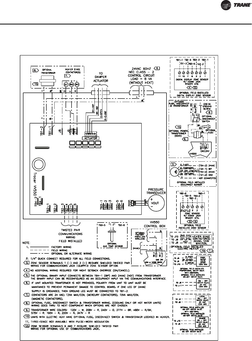
VAV-SVP01A-EN 107
Troubleshooting
Figure 59. VV550 single duct control diagram
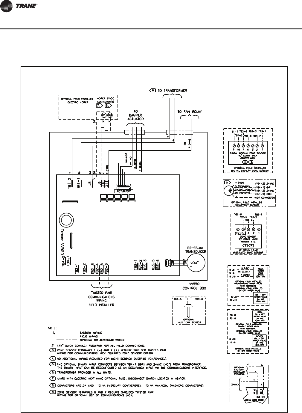
108 VAV-SVP01A-EN
Troubleshooting
Figure 60. VV550 fan-powered control diagram

VAV-SVP01A-EN 109
Troubleshooting
Figure 61. Single duct with single phase voltage electric heat
WIRING
FIELD INSTALLED
TWISTED PAIR
COMMUNICATIONS
1ST STAGE
3RD STAGE
CONTACTOR
2ND STAGE
CONTACTOR
CONTACTOR
Tracer VV550
TB4_2
TB4_1
TB2_2
TB2_1
TB2_4
TB2_3
TB1_2
TB1_1
J8
J9
Y
BL
BR
O
MAGNETIC CONTACTORS (MAGN)
MERCURY CONTACTORS (MERC)
SINGLE PHASE
LINE VOLTAGES
1
CONTACTORS
HEAT
3
2
347
480
208
240
277
STAGES
TB2_5
TB2_6
TB3_1
TB3_2
TB3_5
TB3_3
BK
TB3_6
FLOW
R
G
VOUT
TRANSDUCER
-
+
ACTUATOR
J10
J11
ACTUATOR
V
R
HOT
HOT
OPEN
CLOSE
WIRING
DAMPER
PRESSURE
24V
HEATER TERMINAL BOX
OPTIONAL
TRANSFORMER
(208, 240 & 480)
FUSE
OPTIONAL
(SEE NAMEPLATE)
LINE VOLTAGE
V
O
AIR FLOW
SWITCH
BL
Y
OPTIONAL
THERMAL
BR
CUTOUT
R
Y
BL
Y
AUTO RESET
CUTOUT
MANUAL
OPTIONAL
FUSE
OPTIONAL
DISCONNECT
SWITCH
L1 L2
T
G
L1 L2 - 208, 240
L1 L2 N - 480
L1 N - 277, 347
L1 N
L1 N
G
WIRELESS
INSTALLED
24VAC
OPTIONAL FIELD INSTALLED
DIGITAL DISPLAY ZONE SENSOR
DIGITAL DISPLAY ZONE SENSOR
BL
VV550 BOARD
BL
24V
GND
TB1-1
TB1-2
Y
Y
TB3-3
7
TB1-1
TB1-2
W/ COMM. JACK
REMOTE MTD.
FACTORY
OPTIONAL
11 10 236 1
W/ COMM. JACK
ZONE SENSOR
OPTIONAL FIELD
TB2-6
INSTALLED ZONE SENSOR
TB3-3
TB2-5
TB3-1
TB3-2
1(-)
REMOTE MTD.
3
2(+) 2 1
TB2-6
TB2-5
TB3-1
TB3-2
HEATER TERMINALS - TYPICAL OF SINGLE PHASE VOLTAGES
SINGLE DUCT UNITS - VV550
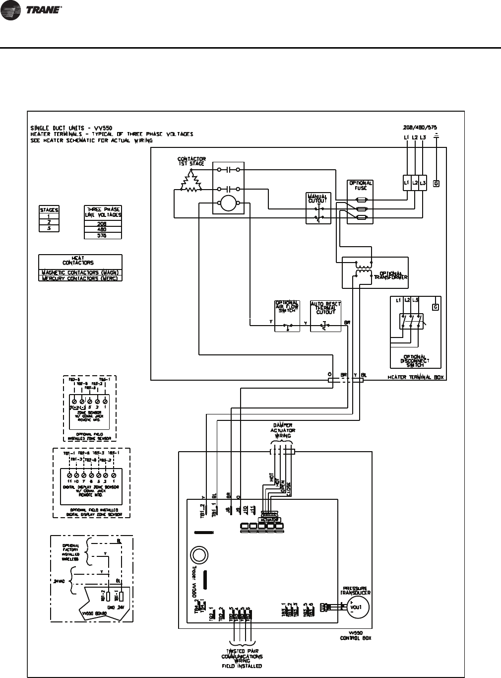
110 VAV-SVP01A-EN
Troubleshooting
Figure 62. Single duct with three phase voltage electric heat
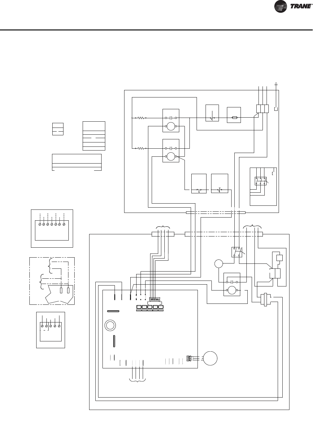
VAV-SVP01A-EN 111
Troubleshooting
Figure 63. SCR/PSC fan-powered with single phase voltage electric heat
TB3_3
1ST STAGE
2ND STAGE
CONTACTOR
CONTACTOR
TB3_2
TB4_1
TB4_2
COMMUNICATIONS
FIELD INSTALLED
TB2_1
TB2_2
TWISTED PAIR
WIRING
TB2_5
TB2_3
TB2_4
TB2_6
TB3_1
TB1_1
TB1_2
Tracer VV550
Y
BL
ACTUATOR
J10
J8
BR
J9
O
R
J11
V
HOT
HOT
CLOSE
OPEN
CONTACTORS
MAGNETIC CONTACTORS (MAGN)
MERCURY CONTACTORS (MERC)
2
HEAT
STAGES
1
208
240
277
480
347
DAMPER
WIRING
ACTUATOR
SINGLE PHASE
LINE VOLTAGES
TRANSFORMER
SPEED
BLOCK
TERMINAL
CONTROL
R
TB3_6
TB3_5
CONTROL BOX
FLOW
VV550
G
BK VOUT
-
PRESSURE
TRANSDUCER
BK
DISCONNECT
+
OPTIONAL
FUSE
BK
R
1
2
3
4
SWITCH
RELAY
MOTOR
BK
BK
BR
BK
W
W
CONTROL BOX
VV550
BL
24V
Y
BR W
MOTOR
W W
L1 L2 N - 208, 240, 480
L1 N - 277, 347
OPTIONAL
DISCONNECT
SWITCH
HEATER TERMINAL BOX
AUTO RESET
CUTOUT
THERMAL
Y
Y
V
O
OPTIONAL
AIR FLOW
SWITCH
BR
BK
TO FAN
MOTOR
W
L1 L2
CUTOUT
MANUAL
OPTIONAL
(SEE NAMEPLATE)
LINE VOLTAGE
FUSE
L1
L1
N
G
N
L2 G
NL2
OPTIONAL FIELD
INSTALLED ZONE SENSOR
ZONE SENSOR
REMOTE MTD.
W/ COMM. JACK
2 1
TB2-5
TB2-6
1(-)2(+) 3
TB3-2
TB3-3
TB3-1
VV550 BOARD
INSTALLED
WIRELESS
24VAC
TB1-1
TB1-2
GND 24V
BL
Y
Y
BL
OPTIONAL
FACTORY
TB2-5
TB3-3
W/ COMM. JACK
DIGITAL DISPLAY ZONE SENSOR
REMOT E MTD .
OPTIONAL FIELD INST ALLED
DIGITAL DISPLAY ZONE SENSOR
7 136 2
TB3-2
TB3-1
TB1-1
TB1-2
11 10
TB2-6
HEATER TERMINALS - TYPICAL OF SINGLE PHASE VOLTAGES
FAN-POWERED UNITS - VV550

112 VAV-SVP01A-EN
Troubleshooting
Figure 64. SCR/PSC fan-powered with three phase voltage electric heat
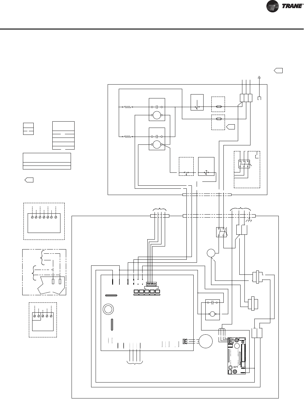
VAV-SVP01A-EN 11 3
Troubleshooting
Figure 65. ECM fan-powered with single phase voltage electric heat
ACTUATOR
TB3-3
TB3-2
OPTIONAL FIELD
INSTALLED ZONE SENSOR
ZONE SENSOR
W/ COMM. JACK
REMOTE MTD.
TB2-6
2(+) 1(-) 3
TB2-5
2 1
TB3-1
VV550 BOARD
24VAC
FACTORY
OPTIONAL
WIRELESS
INSTALLED
GND
TB1-2
TB1-1
24V
BL
Y
Y
BL
TWISTED PAIR
COMMUNICATIONS
FIELD INSTALLED
WIRING
TB4_2
Tracer VV550
TB2_3
TB4_1
TB2_1
TB2_2
TB2_6
TB2_4
TB2_5
BL
TB1_1
TB1_2Y
J8BR
J10
J9O
V
J11R
FUSE IS INSTALLED IF FUSE IS SELECTED.
FOR VOLTAGES 208, 240, & 480 A SECOND
480
MAGNETIC CONTACTORS (MAGN)
MERCURY CONTACTORS (MERC)
SINGLE PHASE
LINE VOLTAGES
208
2
TB2-5
DIGITAL DISPLAY ZONE SENSOR
REMOT E MTD.
OPTIONAL FIELD INSTALLED
DIGITAL DISPLAY ZONE SENSOR
W/ COMM. JACK
11 10 7 6
TB1-2
TB1-1 TB2-6
3 2 1
TB3-1TB3-3
TB3-2
CONTACTORS
HEAT
1.
277
347
240
STAGES
1
CLOSE
BOARD
ECM
TRANSDUCER
TB3_1
TB3_2
TB3_3
TB3_5
TB3_6
FLOW
BK BL
24V
RELAY
MOTOR
+
PRESSURE
-
VOUT
R
BK
G
BL
1
2
W
BK
G
R
3
R
4
FUSE
OPTIONAL
BK
NEUT.
24V
CONTROL BOX
VV550
POWER FACTOR
CORRECTION CHOKE
Y
BK
TERMINAL
BL
BLOCK
TRANSFORMER
BK
Y
BL
24V
ECM MOTOR
1.
HEATER TERMINAL BOX
OPTIONAL
AIR FLOW
O
OPEN
HOT
HOT
ACTUATOR
WIRING
DAMPER
Y
V
SWITCH
BR
DISCONNECT
SWITCH
BK
BK
W
W
BK
W
AUTO RESET
HOT
THERMAL
Y
CUTOUT
2ND STAGE
CONTACTOR
1ST STAGE
CONTACTOR
CUTOUT
MANUAL
OPTIONAL
FUSE
OPTIONAL
FUSE
(SEE NAMEPLATE)
LINE VOLTAGE
TERMINAL
BLOCK
BR
W
W
BK
G
TO
DISCONNECT
OPTIONAL
SWITCH
L1 L2 N
G
L2 NL1
L1 L2 NG
L1 L2 N - 208, 240, 480
L1 N - 277, 347
1.
FAN-POWERED UNITS - VV550 - ECM MOTOR
HEATER TERMINALS - TYPICAL OF SINGLE PHASE VOLTAGES
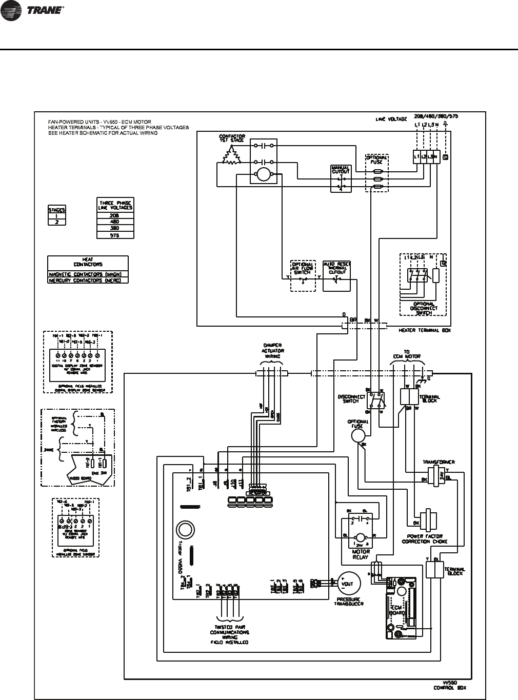
114 VAV-SVP01A-EN
Troubleshooting
Figure 66. ECM fan-powered with three phase voltage electric heat

www.trane.com
For more information, contact your local Trane
office or e-mail us at comfort@trane.com
Literature Order Number VAV-SVP01A-EN
Date May 2010
Supersedes VAV-SVP01A-EN February 2010
Trane has a policy of continuous product and product data improvement and reserves the right to
change design and specifications without notice.
