Trane Voyager 12 5 To 25 Tons Installation Instructions Human Interface Upgrade Voyager™ Tons, Precedent™ 3 10 RSP SVN001A EN February 2015
2015-04-02
: Trane Trane-Voyager-12-5-To-25-Tons-Installation-Instructions-684209 trane-voyager-12-5-to-25-tons-installation-instructions-684209 trane pdf
Open the PDF directly: View PDF ![]() .
.
Page Count: 16

SAFETY WARNING
Only qualified personnel should install and service the equipment. The installation, starting up, and servicing
of heating, ventilating, and air-conditioning equipment can be hazardous and requires specific knowledge and
training. Improperly installed, adjusted or altered equipment by an unqualified person could result in death or
serious injury. When working on the equipment, observe all precautions in the literature and on the tags,
stickers, and labels that are attached to the equipment.
Human Interface Upgrade
Voyager™ 12½ to 25 Tons, Precedent™ 3 to 10 Tons
Installation
Instructions
RSP-SVN001A-EN
February 2015
© 2015Trane All rights reserved RSP-SVN001A-EN
Introduction
Read this manual thoroughly before operating or servicing
this unit.
Warnings, Cautions, and Notices
Safety advisories appear throughout this manual as
required.Your personal safety and the proper operation of
this machine depend upon the strict observance of these
precautions.
Important Environmental Concerns
Scientific research has shown that certain man-made
chemicals can affect the earth’s naturally occurring
stratospheric ozone layer when released to the
atmosphere. In particular, several of the identified
chemicals that may affect the ozone layer are refrigerants
that contain Chlorine, Fluorine and Carbon (CFCs) and
those containing Hydrogen, Chlorine, Fluorine and
Carbon (HCFCs). Not all refrigerants containing these
compounds have the same potential impact to the
environment.Trane advocates the responsible handling of
all refrigerants-including industry replacements for CFCs
such as HCFCs and HFCs.
Important Responsible Refrigerant
Practices
Trane believes that responsible refrigerant practices are
important to the environment, our customers, and the air
conditioning industry. All technicians who handle
refrigerants must be certified.The Federal Clean Air Act
(Section 608) sets forth the requirements for handling,
reclaiming, recovering and recycling of certain
refrigerants and the equipment that is used in these
service procedures. In addition, some states or
municipalities may have additional requirements that
must also be adhered to for responsible management of
refrigerants. Know the applicable laws and follow them.
The three types of advisories are defined as follows:
WARNING Indicates a potentially hazardous
situation which, if not avoided, could
result in death or serious injury.
CAUTIONsIndicates a potentially hazardous
situation which, if not avoided, could
result in minor or moderate injury. It
could also be used to alert against
unsafe practices.
NOTICE Indicates a situation that could result in
equipment or property-damage only
accidents.
WARNING
Proper Field Wiring and Grounding
Required!
Failure to follow code could result in death or serious
injury. All field wiring MUST be performed by qualified
personnel. Improperly installed and grounded field
wiring poses FIRE and ELECTROCUTION hazards.To
avoid these hazards, you MUST follow requirements for
field wiring installation and grounding as described in
NEC and your local/state electrical codes.
WARNING
Personal Protective Equipment (PPE)
Required!
Installing/servicing this unit could result in exposure to
electrical, mechanical and chemical hazards.
• Before installing/servicing this unit, technicians
MUST put on all PPE required for the work being
undertaken (Examples; cut resistant gloves/sleeves,
butyl gloves, safety glasses, hard hat/bump cap, fall
protection, electrical PPE and arc flash clothing).
ALWAYS refer to appropriate Material Safety Data
Sheets (MSDS)/Safety Data Sheets (SDS) and OSHA
guidelines for proper PPE.
• When working with or around hazardous chemicals,
ALWAYS refer to the appropriate MSDS/SDS and
OSHA/GHS (Global Harmonized System of
Classification and Labelling of Chemicals) guidelines
for information on allowable personal exposure
levels, proper respiratory protection and handling
instructions.
• If there is a risk of energized electrical contact, arc, or
flash, technicians MUST put on all PPE in accordance
with OSHA, NFPA 70E, or other country-specific
requirements for arc flash protection, PRIOR to
servicing the unit. NEVER PERFORM ANY
SWITCHING, DISCONNECTING, OR VOLTAGE
TESTING WITHOUT PROPER ELECTRICAL PPE AND
ARC FLASH CLOTHING. ENSURE ELECTRICAL
METERS AND EQUIPMENT ARE PROPERLY RATED
FOR INTENDED VOLTAGE.
Failure to follow instructions could result in death or
serious injury.

Introduction
RSP-SVN001A-EN 3
Copyright
This document and the information in it are the property of
Trane, and may not be used or reproduced in whole or in
part without written permission.Trane reserves the right
to revise this publication at any time, and to make changes
to its content without obligation to notify any person of
such revision or change.
Trademarks
All trademarks referenced in this document are the
trademarks of their respective owners.
4 RSP-SVN001A-EN
Table of Contents
Introduction ............................. 2
Warnings, Cautions, and Notices ........ 2
Important Environmental Concerns ..... 2
Important Responsible Refrigerant Practices
2
Copyright ............................. 3
Table of Contents ........................ 4
Models Supported ...................... 5
Voyager™ 12½ to 25 Tons ............. 5
Precedent™ 3 to 10 Tons .............. 5
General Information ..................... 6
Part Identification .................... 6
Tools List ........................... 7
Voyager™ Light Commercial Installation In-
structions ............................... 8
Precedent™ Unit Installation Instructions .11
RSP-SVN001A-EN 5
Models Supported
Voyager™ 12½ to 25 Tons
All models that have ReliaTel™ controls installed. To
identify if ReliaTel™ controls are installed, validate digit 9
of the model number is an “R.”
Precedent™ 3 to 10 Tons
All models that have ReliaTel™ controls installed (where
digit 9 of the model number is an “R’”) except
Precedent™ A cabinets, which include the following:
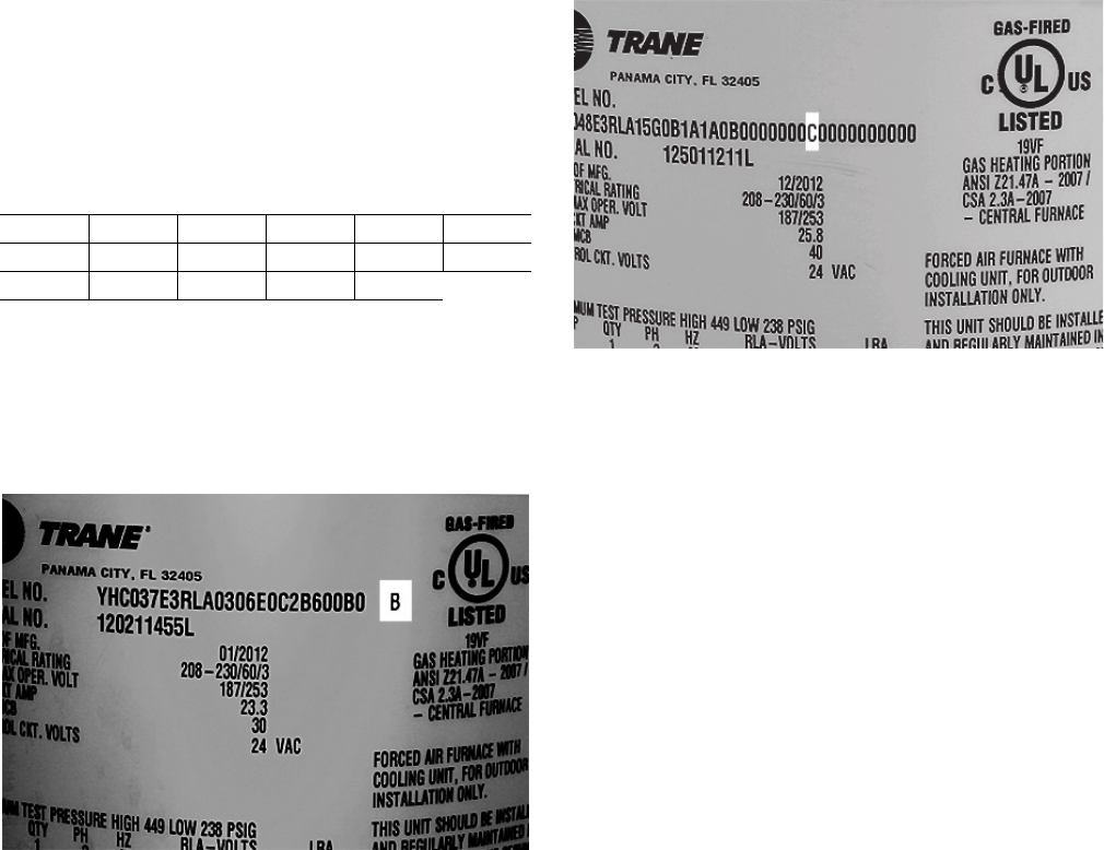
To identify the type of Precedent™ cabinet for older
models, view the letter after the model number on the
nameplate. For newer models, it is the 30th digit of the
model number.
Table 1. Precedent™ A cabinet models
TSC036A YHC036A THC048A WSC048A WSC060A THC043A
THC036A WSC036A YSC048A TSC060A THC033A YHC043A
YSC036A TSC048A YHC048A YSC060A YHC033A
Figure 1. Cabinet identification on nameplate, older
models
Figure 2. Cabinet identification on nameplate, newer
models
6 RSP-SVN001A-EN
General Information
The information provided in this manual is intended for
use when adding human interface support to a Precedent
or Voyager™ Light Commercial unit that has ReliaTel™
controls.The work involved in this upgrade consists of the
following:
• Updating to the latest ReliaTel™ Refrigeration Module
(RTRM) to MOD02617
• Installing theTD-5 human interface mounting bracket
• Mounting aTD-5 display to the human interface
mounting bracket
• Connecting theTD-5 human interface cable to the
RTRM
TheTD-5 human interface allows you to view historic
alarms, reports, graph specific data, create setpoints, and
save graph data to a USB device for further diagnosis.
Detailed information on the capabilities of theTD-5 can be
found in theTracer™TD-5 Display for ReliaTel™ Controller
Installation, Operation and Maintenance Guide (RT-
SVX49*-EN).
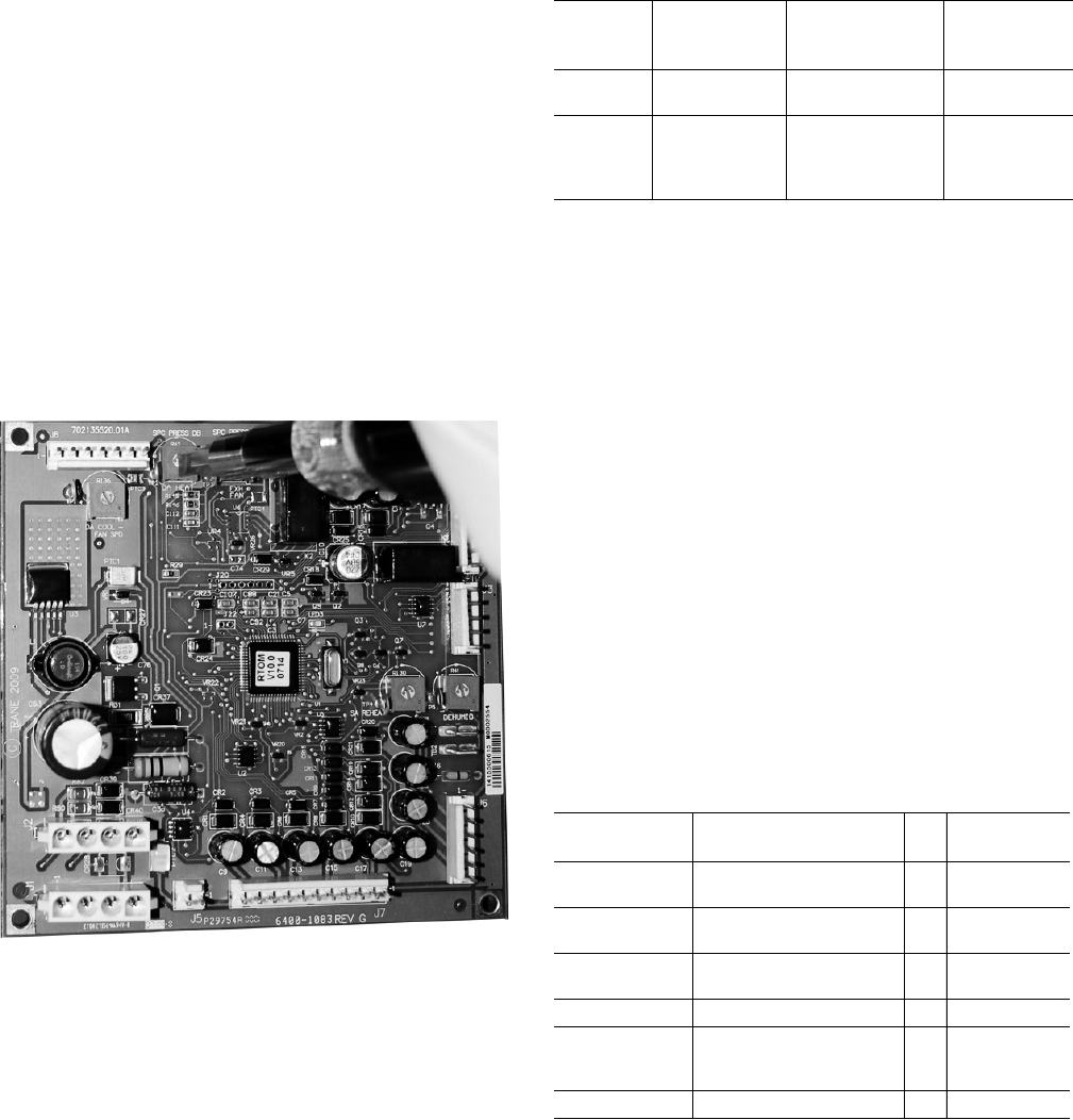
A number of setpoints can be changed by using the
different potentiometers on each control board.To change
the setpoint, use a screw driver to turn the potentiometers
to a specific value.
To view all potentiometer setpoint values, put theTD-5
human interface in Read mode by going to Settings >
Setup > Display Read Only Mode.
In Writer mode, theTD-5 can override the setpoint values
created from the potentiometers, making setpoint
configuration easier.
If theTD-5 human interface is disconnected from the
ReliaTel™ Refrigeration Module, the local setpoints from
the potentiometer are used. Note that setpoints created
from a building automation system (BAS) take precedence
over setpoints created by theTD-5.
Additional modules are available as options that have the
capability to create setpoints. Table 2 defines these
optional modules:
Note: This does not mean that older RTOM and RTEM
modules are unusable.TheTD-5 human interface
can still gather data from older RTOM and RTEM
boards in addition to having the ability to create
setpoints.The latest revisions of the RTOM and
RTEM boards require an upgrade to receive the
setpoint functionality described in Table 2.The
revision list of all ReliaTel™ boards is located in the
ReliaTel™ Controller Installation, Operation, and
Maintenance Guide (RT-SVX49*-EN)
This manual refers to other pieces of literature at various
points.The referenced literature is not included in the
upgrade package unless noted. It is available for download
from through the online literature repository.
If you need technical assistance during installation,
contact Light CommercialTechnical Service in Clarksville,
TN. Ensure installation is performed by a qualified service
technician.
Part Identification
The following tables provides part identification
information.
Figure 3. Example of changing potentiometer value on
the RTOM
Table 2. Optional setpoints
Option Model No.
Identification Setpoint
Supported
Control
Module
17 SEER Digit 6 = 7 Supply fan
adjustment RTOM
MOD02554
Economizer Digit 14 = C, D, E,
F, G, or H
Economizer
reference enthalpy
Economizer dry bulb
enabled
RTEM
MOD02618
Table 3. Voyager™ Light Commercial (KIT17429)
Aftermarket
Part # Description Qty Factory
Part #
MOD02617 Module, ReliaTel™ refrig
dual circuit cool/hp 1 X13605867160
CNT07131 TD-5 display with Modbus,
USB host support 1 X13760344010
BRK04416 Bracket, human interface
mounting 1 438577210100
BRK04519 Bracket, mounting bracket 1 438577220100
SCR00909 Screw, Phillips panhead
0.75" thread rolling zinc
plate 6-32 2 X25330033130
SCR01623 Screw, 10-16 UNC x 1/2 3 X25240209010

General Information
RSP-SVN001A-EN 7
Tools List
• Cordless drill
•1/8" drill bit
•Phillips driver bit (#2/standard)
•5/16" hex nut driver bit
• Phillips screwdriver
• Sharpie magic marker
• Zip tie
SCR02375 Screw, brass Phillips
panhead 8 mm machine,
M4-8 4 X25020715010
IRT00017 Stop bumper,
.486 OD x .81 LG 3 X20070029010
Installation documentation 1
Optional Parts
MOD02554 Module, ReliaTel™ options,
RTOM (to create supply fan
adjustment setpoint) 1 X13650868090
MOD02618
Module, ReliaTel™
economizer logic, RTEM,
ReliaTel™ (to create
economizer ref enthalpy
and economizer dry bulb
enabled setpoints)
1 X13651513030
Table 4. Precedent™ (KIT17430)
Aftermarket
Part # Description Qty Factory
Part #
MOD02617 Module, ReliaTel™ refrig
dual circuit cool/hp 1 X13650867160
CNT07131 TD-5 display with Modbus,
USB host support 1 X13750344010
BRK04546 TD-5 mounting bracket 1 507115960001
SCR02375 Screw, brass Phillips
panhead 8 mm machine,
M4-8 4 X25020715010
SCR01623 Screw, 10-16 UNC x 1/2 3 X25240209010
IRT00017 Stop bumper,
.486 OD x .81 LG 3 X20070029010
Installation documentation 1
Optional Parts
MOD02554 Module, ReliaTel™ options,
RTOM (to create supply fan
adjustment setpoint) 1 X13650868090
MOD02618
Module, ReliaTel™
Economizer Logic, RTEM,
ReliaTel™ (to create
economizer ref enthalpy
and economizer dry bulb
enabled setpoints)
1 X13651513040
Table 3. Voyager™ Light Commercial (KIT17429)
Aftermarket
Part # Description Qty Factory
Part #

8 RSP-SVN001A-EN
Voyager™ Light Commercial Installation Instructions
1. Turn off the main power disconnect to the unit and then
follow the correct lockout/tagout safety procedures to
ensure that main power to the machine cannot be
inadvertently restored.
2. Open the control cabinet door panel to locate the
RTRM board.
•For standard panels, remove the two screws at the
bottom of the control door panel.
•Depending on the model, you may need to remove
the high voltage sheet metal that is attached by
recessed screws.
3. Replace the RTRM as follows:
a. Detach the cables from the RTRM board that go to
a thermostat and sensors.
b. Once all cables/wires are detached, remove the
existing RTRM board from the back of the cabinet
and attach the newer RTRM board.
c. Reconnect all cables/wires that were removed from
the existing module to the new module.
To view detailed information on each connection of the
RTRM board, refer to the ReliaTel™ Microprocessor
Controls Service Diagnostics Manual (RT-SVD03*-EN).
4. Mount the TD-5 human interface bracket as follows:
a. Pre-drill holes for the TD-5 human interface
mounting bracket (BRK04519). Voyager™ Light
Commercial models manufactured after January
2014 already have pre-drilled holes for the TD-5
human interface mounting bracket. If the model
was manufactured before January 2014, pre-drilled
holes are required.
b. Place theTD-5 human interface mounting bracket
BRK04519 directly below the control compartment
against the inside of the unit. Use theTD-5
mounting bracket BRK04519 as a template to mark
the holes of the bracket.
c. Before drilling the holes, ensure that nothing will be
damaged on the other side of the sheet metal.Then
pre-drill the marked holes, using a 1/8" drill bit.
d. Fasten theTD-5 mounting bracket, using a 5/16" nut
driver and the 10-16 UNC x ½" screws.
e. Fasten the stop bumpers (IRT00017) around the
bottom screw thread.
5. Mount theTD-5 human interface(CNT07131) to bracket
BRK04416, as follows:
a. The notches on bracket BRK04416 must be located
at the top and bottom of theTD-5.
b. Use a Phillips screw driver and 4 of the 4M 8 mm
screws to fasten theTD-5 human interface onto
BRK04416.
WARNING
Hazardous Voltage w/Capacitors!
Failure to disconnect power and discharge capacitors
before servicing could result in death or serious injury.
Disconnect all electric power, including remote
disconnects and discharge all motor start/run
capacitors before servicing. Follow proper lockout/
tagout procedures to ensure the power cannot be
inadvertently energized. For variable frequency drives or
other energy storing components provided by Trane or
others, refer to the appropriate manufacturer’s literature
for allowable waiting periods for discharge of
capacitors. Verify with an appropriate voltmeter that all
capacitors have discharged.
For additional information regarding the safe discharge
of capacitors, see PROD-SVB06A-EN
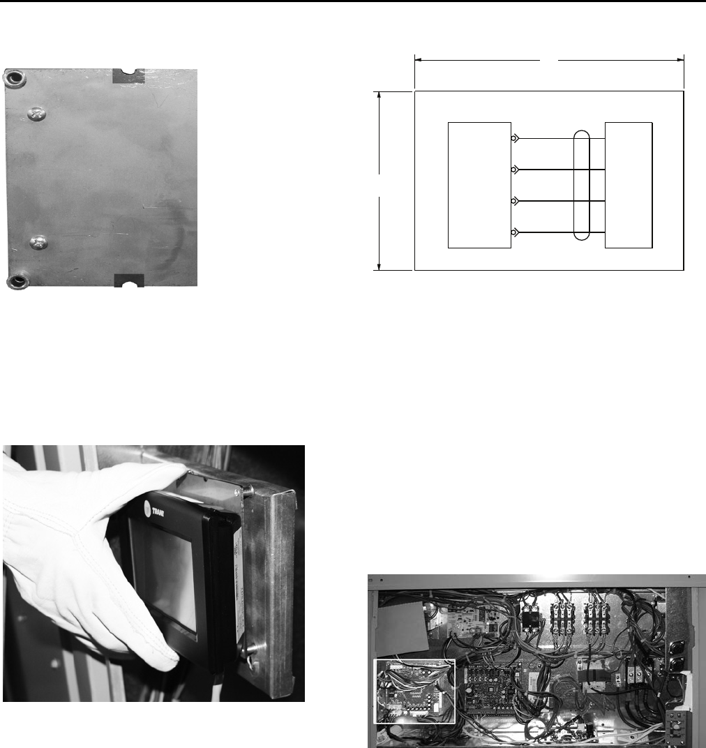
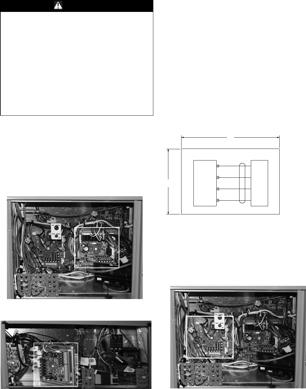
Figure 4. Voyager™ Light Commercial - RTRM board
Figure 5. Installing the TD-5 human interface
mounting bracket (BRK04519)
Voyager™ Light Commercial Installation Instructions
RSP-SVN001A-EN 9
6. Place theTD-5 human interface and BRK04416 onto the
TD-5 mounting bracket BRK04519, using the TD-5
mounting bracket eyelets. At any time, theTD-5 human
interface can be held for navigational purposes.Two
optional screws are included to fasten the two
mounting brackets.
7. Run theTD-5 cord through the control compartment
base floor hole.
8. Insert theTD-5 cord into the J10 connection on the
RTRM board, ensuring that the cord is not pulled tight
against any sheet metal edges that could cause
damage to the cord.
9. Optional: If the RTOM board was purchased, which
allows the ability to create the Supply Fan Adjustment
setpoint, remove the older RTOM board and replace it
with the newer RTOM board as follows:
a. Ensure that the newer RTOM board’s local
potentiometer values are identical to the replaced
RTOM board.
b. Once all cables/wires are detached, remove the
existing RTOM board from the back of the cabinet
and attach the newer RTOM board.
c. Reconnect all cables/wires that were removed from
the existing module to the new module.
To view detailed information on each connection of the
RTOM board, refer to the ReliaTel™ Microprocessor
Controls Service Diagnostics Manual (RT-SVD03*-EN).
10. Optional: If the RTEM board was purchased, which
allows the ability to create the economizer reference
enthalpy and economizer dry bulb enabled setpoint,
remove the RTEM board and replace it with the newer
RTEM board as follows:
a. Ensure the newer RTEM board’s local
potentiometer values are identical to the replaced
RTEM board.
Figure 6. Mounting the TD-5 human interface on
bracket (BRK04416)
Figure 7. Mount the TD-5 human interface on the
eyelet bracket (BRK04519
Figure 8. TD-5 Human Interface Schematic (2313-1548)
Figure 9. RTOM Board
SCHEMATIC - HUMAN INTERFACE
J10-1
J10-2
J10-3
J10-4
RTRM HI
3.0
TRIM
2.0
TRIM
CBLHI
RED
BLACK
GRAY
BLUE
1
2
3
4
RTRM-P10
RTRM-P10
RTRM-P10
RTRM-P10
2313-1548-0100

Voyager™ Light Commercial Installation Instructions
10 RSP-SVN001A-EN
b. Once all cables are detached, remove the existing
RTEM from the unit and attach the newer RTEM
board.
c. Reconnect all cables/wires that were removed from
the existing module to the new module.
To view detailed information on each connection of the
RTEM board, refer to the ReliaTel™ Microprocessor
Controls Service Diagnostics Manual (RT-SVD03*-EN).
11. Turn on the unit by turning the disconnect to the on
position.
12.To start the unit, press the Auto button in the upper
right hand corner of theTD-5 human interface.
RSP-SVN001A-EN 11
Precedent™ Unit Installation Instructions
1. Turn off the main power disconnect to the unit and then
follow the correct lockout/tagout safety procedures to
ensure that main power to the machine cannot be
inadvertently restored.
2. Open the control cabinet door panel to locate the
RTRM board.
•For standard panels, remove the two screws at the
bottom of the control door panel.
3. Replace the RTRM as follows:
a. Detach the cables from the RTRM board that go to
a thermostat and sensors.
b. Once all cables are detached, remove the existing
RTRM board from the back of the cabinet and attach
the new RTRM board.
c. Reconnect all cables/wires that were removed from
the existing module to the new module.
To view detailed information on each connection of the
RTRM board can be viewed in the ReliaTel™
Microprocessor Controls Service Diagnostics Manual
(RT-SVD03*-EN).
d. Insert theTD-5 cord into the J10 connection on the
RTRM board.
e. Place theTD-5 on top of the unit while mounting the
bracket.
4. Optional: If the RTOM board was purchased, which
allows the ability to create the supply fan adjustment
setpoint, remove the older RTOM board and replace it
with the newer RTOM board as follows:
The RTOM board will be located in either the indoor fan
section or the control panel compartment depending
on the Precedent™ model.
WARNING
Hazardous Voltage w/Capacitors!
Failure to disconnect power and discharge capacitors
before servicing could result in death or serious injury.
Disconnect all electric power, including remote
disconnects and discharge all motor start/run
capacitors before servicing. Follow proper lockout/
tagout procedures to ensure the power cannot be
inadvertently energized. For variable frequency drives or
other energy storing components provided by Trane or
others, refer to the appropriate manufacturer’s literature
for allowable waiting periods for discharge of
capacitors. Verify with an appropriate voltmeter that all
capacitors have discharged.
For additional information regarding the safe discharge
of capacitors, see PROD-SVB06A-EN
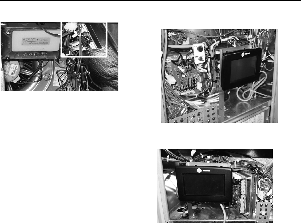
Figure 10. Precedent™ E Cabinet - RTRM board
Figure 11. Precedent™ B Cabinet - RTRM board
Figure 12. TD-5 Human Interface Schematic (2313-1548)
Figure 13. Precedent™ E Cabinet - RTOM board
SCHEMATIC - HUMAN INTERFACE
J10-1
J10-2
J10-3
J10-4
RTRM HI
3.0
TRIM
2.0
TRIM
CBLHI
RED
BLACK
GRAY
BLUE
1
2
3
4
RTRM-P10
RTRM-P10
RTRM-P10
RTRM-P10
2313-1548-0100
Precedent™ Unit Installation Instructions
12 RSP-SVN001A-EN
a. Ensure the newer RTOM board's local
potentiometer values are identical to the replaced
RTOM board.
b. Once all cables/wires are detached, remove the
existing RTOM board from the back of the cabinet
and attach the newer RTOM board.
c. Reconnect all cables/wires that were removed from
the existing module to the new module.
To view detailed information on each connection of the
RTOM board can be viewed in the ReliaTel
Microprocessor Controls Service Diagnostics Manual
(RT-SVD03*-EN).
5. Mount the TD-5 human interface bracket as follows:
a. Place theTD-5 human interface mounting bracket in
the front of the control compartment. Use theTD-5
human interface mounting bracket as a template to
mark the holes. For units that have the gas/heat
option and a voltage of either 450/60/3 or 575/60/3
an additional sensor and transformer may be
attached in this area.
b. Before drilling the holes, ensure that nothing will be
damaged on the other side of the sheet metal.Then
pre-drill the marked holes with a 1/8" drill bit.
c. Fasten theTD-5 mounting bracket, using a 5/16" nut
driver and the 10-16 UNC x ½” screws.
d. Fasten the stop bumpers (IRT00017) around the
bottom screw thread.
6. Mount theTD-5 display (CNT07131) to theTD-5 human
interface mounting bracket.
This bracket gives the user the ability to hold theTD-5
human interface in their hand while diagnosing issues.
a. Fasten 3 of the 4M 8 mm screws into the top two
holes and bottom left hand hole of theTD-5 human
interface making sure 1 mm is left to place the
TD-5 human interface into the recessed screw
holes. Loctite can be optionally used when
fastening the screws.
b. TheTD-5 can be permanently fastened by installing
the 4th screw in the bottom right hand hole once the
TD-5 human interface is mounted.
c. Using the plastic zip tie, (fastened to the hole in the
right hand leg of theTD-5 bracket) bundle theTD-5
cord to ensure it is isolated from the other controls.
Do not pull the cord tight against any sheet metal
edges.This could cause damage to the cord.
7. Optional: If the RTEM board was purchased, which
allows the ability to create the economizer reference
enthalpy and economizer dry bulb enabled setpoint,
remove the RTEM board and replace it with the newer
RTEM board as follows:
a. Ensure the newer RTEM board's local
potentiometer values are identical to the replaced
RTEM board.
b. Once all cables are attached remove the existing
RTEM from the unit and attach the newer RTEM
board.
c. Reconnect all cables/wires that were removed from
the existing module to the new module.
To view detailed information on each connection of the
RTEM board, refer to the ReliaTel™ Microprocessor
Controls Service Diagnostics Manual (RT-SVD03*-EN).
Figure 14. Precedent™ B Cabinet - RTOM board Figure 15. Precedent™ E Cabinet - TD-5 Human
Interface
Figure 16. Precedent™ B Cabinet - TD-5 Human
Interface
Precedent™ Unit Installation Instructions
RSP-SVN001A-EN 13
8. Turn on the unit by turning the disconnect to the on
position.
9. To start the unit, press the Auto button in the upper
right hand corner of theTD-5 human interface.
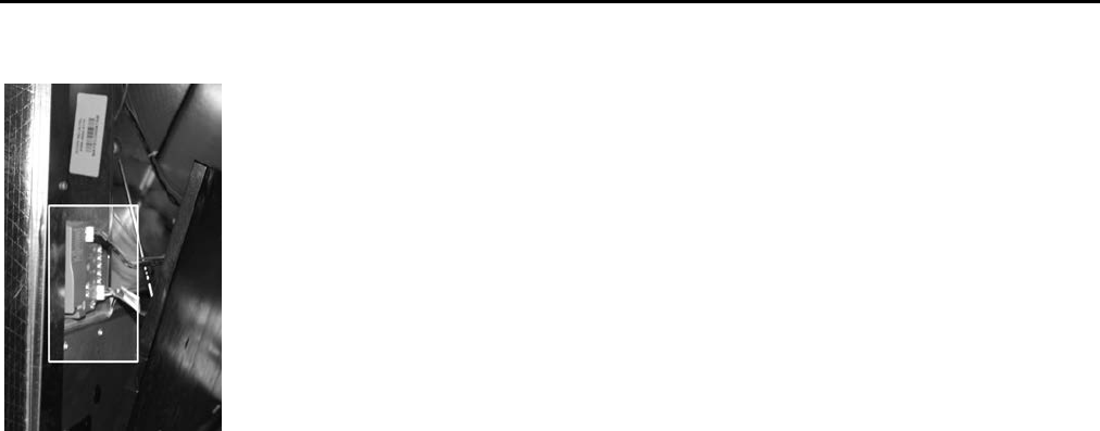
Figure 17. Precedent™ E Cabinet - RTEM Location

The manufacturer optimizes the performance of homes and buildings around the world. A business of Ingersoll Rand,
the leader in creating and sustaining safe, comfortable and energy efficient environments,the manufacturer offers a
broad portfolio of advanced controls and HVAC systems, comprehensive building services, and parts. For more
information, visit www.IRCO.com.
The manufacturer has a policy of continuous product and product data improvement and reserves the right to change design and specifications without notice.
We are committed to using environmentally
conscious print practices that reduce waste.
© 2015Trane All rights reserved
RSP-SVN001A-EN 10 Feb 2015
(NEW)
