Trane Vuve Vertical Classroom Catalogue UV PRC003 EN (04 Jun 2013)
2015-04-02
: Trane Trane-Vuve-Vertical-Classroom-Catalogue-684296 trane-vuve-vertical-classroom-catalogue-684296 trane pdf
Open the PDF directly: View PDF ![]() .
.
Page Count: 91
Vertical Classroom Unit Ventilator
750 cfm to 1500 cfm
June 2013 UV-PRC003-EN
Product Catalog
UV-PRC003-EN.book Page 1 Tuesday, June 4, 2013 8:59 PM
© 2013 Trane All rights reserved UV-PRC003-EN
Introduction
The Trane Classroom Unit Ventilator
Academic performance of U.S. students depends, in part, on the ability to create a comfortable
learn-friendly surrounding. Being too hot or too cold could hinder a students ability to achieve
academic excellence.
Seasonal changes, mechanical/building disrepair, and even class attendance provide real
challenges to HVAC mechanical systems. The only thing consistent about today’s classroom is its
ability to constantly change. With this in mind, Trane introduces a NEW classroom unit ventilator
design to support today’s changing environment.
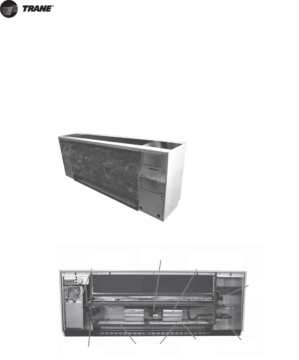
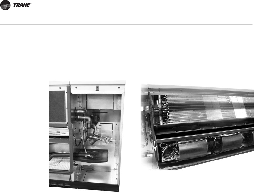
Figure 1. Back view of unit ventilator
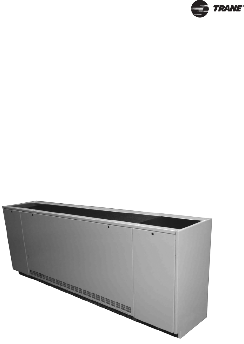
Figure 2. Vertical classroom unit ventilator
Roomy end-pockets for
install-ability and
system customization
Maintenance-free
EC motor with
direct-drive fans Blow-through design provides
freeze protection, sound
attenuation, and safety
Hassle-free
piping
Auxiliary drain
pan option
Sealed coil, but quickly
accessed for cleaning
and visual inspection
Larger fans for
lower sound levels
Off-the-shelf
filter sizing
Linkage-free
outside air damper
UV-PRC003-EN.book Page 2 Tuesday, June 4, 2013 8:59 PM
UV-PRC003-EN 3
Introduction
Trademarks
EarthWise, Integrated Comfort, Rover, Trane, the Trane logo, TOPSS, Tracer, and Tracer Summit are
trademarks or registered trademarks of Trane in the United States and other countries. All
trademarks referenced in this document are the trademarks of their respective owners.
BACnet is a registered trademark of American Society of Heating, Refrigerating and Air-
Conditioning Engineers (ASHRAE); Echelon, LONMARK, LonTalk, and LONWORKS are registered
trademarks of Echelon Corporation.
UV-PRC003-EN.book Page 3 Tuesday, June 4, 2013 8:59 PM

4 UV-PRC003-EN
Table of Contents
Features and Benefits . . . . . . . . . . . . . . . . . . . . . . . . . . . . . . . . . . . . . . . . . . . . . . . . . . . 5
Fit and Finish . . . . . . . . . . . . . . . . . . . . . . . . . . . . . . . . . . . . . . . . . . . . . . . . . . . . . . 5
Install-ability, Service-ability and Maintain-ability . . . . . . . . . . . . . . . . . . . . . . 5
IAQ Features . . . . . . . . . . . . . . . . . . . . . . . . . . . . . . . . . . . . . . . . . . . . . . . . . . . . . . 7
Acoustics . . . . . . . . . . . . . . . . . . . . . . . . . . . . . . . . . . . . . . . . . . . . . . . . . . . . . . . . . 8
Application Considerations . . . . . . . . . . . . . . . . . . . . . . . . . . . . . . . . . . . . . . . . . . . . . 10
A Choice in System Design . . . . . . . . . . . . . . . . . . . . . . . . . . . . . . . . . . . . . . . . . 10
Selection Procedure . . . . . . . . . . . . . . . . . . . . . . . . . . . . . . . . . . . . . . . . . . . . . . . . . . . 21
Model Number Descriptions . . . . . . . . . . . . . . . . . . . . . . . . . . . . . . . . . . . . . . . . . . . . 23
General Data . . . . . . . . . . . . . . . . . . . . . . . . . . . . . . . . . . . . . . . . . . . . . . . . . . . . . . . . . . 25
Performance Data . . . . . . . . . . . . . . . . . . . . . . . . . . . . . . . . . . . . . . . . . . . . . . . . . . . . . 28
Controls . . . . . . . . . . . . . . . . . . . . . . . . . . . . . . . . . . . . . . . . . . . . . . . . . . . . . . . . . . . . . . 64
Fan Speed Switch . . . . . . . . . . . . . . . . . . . . . . . . . . . . . . . . . . . . . . . . . . . . . . . . . 66
Customer Supplied Terminal Interface (CSTI) . . . . . . . . . . . . . . . . . . . . . . . . . 68
Tracer ZN520 Zone Controller . . . . . . . . . . . . . . . . . . . . . . . . . . . . . . . . . . . . . . 69
Tracer UC400 . . . . . . . . . . . . . . . . . . . . . . . . . . . . . . . . . . . . . . . . . . . . . . . . . . . . . 72
Zone Sensors . . . . . . . . . . . . . . . . . . . . . . . . . . . . . . . . . . . . . . . . . . . . . . . . . . . . 74
Valves/Piping Package . . . . . . . . . . . . . . . . . . . . . . . . . . . . . . . . . . . . . . . . . . . . . 76
Jobsite Connections . . . . . . . . . . . . . . . . . . . . . . . . . . . . . . . . . . . . . . . . . . . . . . . . . . . 81
Dimensional Data . . . . . . . . . . . . . . . . . . . . . . . . . . . . . . . . . . . . . . . . . . . . . . . . . . . . . . 82
Mechanical Specifications . . . . . . . . . . . . . . . . . . . . . . . . . . . . . . . . . . . . . . . . . . . . . . 87
UV-PRC003-EN.book Page 4 Tuesday, June 4, 2013 8:59 PM
UV-PRC003-EN 5
Features and Benefits
Fit and Finish
Equipment Size
The vertical unit ventilator delivers from 750 cfm to 1500 cfm. It is physically sized to fit the
replacement or new construction application.
Cabinet Finish
The unit cabinetry is made of a durable industrial grade metal to withstand even the most rigorous
classrooms. A smooth/glossy, appliance grade paint treatment increases the aesthetics of the
equipment while making it durable and easy to maintain.
Access
A three panel front access of the unit ventilator is ergonomically safe for lifting/removal, and allows
speedy set up during field commissioning. This design allows for the end pocket of the unit
ventilator to be open while the fan (airside) section stays closed. The panel design supports a clean
fit and finish while providing effortless access for filter change-out.
Top access to the unit mounted fan speed/sensor option was developed with the teacher or
administrative staff in mind. Access to the sensor may be made through a lock/key, or through an
easy open door.
Install-ability, Service-ability and Maintain-ability
Spacious End Pockets
Easy access to piping and controls is made through the roomy equipment end pocket design. The
coil headers and drain connections are made within the unit chassis, freeing-up valuable space in
the end pockets for piping or field add-ins. This also grants a tighter seal to prevent air leakage.
The roomy end pocket design Figure 4, p. 6 allows for application requirements such as an optional
auxiliary drain pan. The auxiliary pan may be placed under the factory or field piping package.
Figure 3. Fit and finish
UV-PRC003-EN.book Page 5 Tuesday, June 4, 2013 8:59 PM
6 UV-PRC003-EN
Features and Benefits
Sliding Fan Deck
Convenient access to the fan motor and fan wheels for maintenance and serviceability is made in
part of the easy-slide design of the unit ventilator fan board, Figure 5. The fan board assembly
offers hassle free access to the contractor or maintenance technician. As an added benefit, Trane’s
unit ventilator includes Electronically Commutated Motors (ECM) as standard.
Energy Efficiency
Trane has a commitment to providing premium quality products that has led to the exclusive use
of Electronically Commutated Motors (ECM) in all unit ventilator models. These brushless DC
motors incorporate the latest technology for optimized energy efficiency, acoustical abatement,
maintenance free and extended motor life. Each motor has a built-in microprocessor that allows
for programmability, soft ramp-up, better airflow control, and serial communication.
• Trane units equipped with ECMs are significantly more efficient than a Permanent Split
Capacitor (PSC) motor.
• Lower operating costs on average of 50 percent (versus a PSC motor).
• The Reduced FLA option allows units to ship with a nameplate FLA rating much lower than a
typical ECM unit.
Filters
Trane unit ventilators utilize an off-the-shelf filter design to reduce or eliminate local stocking of
filters in the school. See “General Data,” p. 25 for standard filter sizes.
Note: High efficiency options, MERV 8 and MERV 13, are available. These filters provide greater
resistance and dust holding capabilities.
Hinged Control Box
The hinged control box design maintains easy access to the electrical for connection while
supporting less potential for damage on the job site from the different construction trades.
Figure 4. Spacious end pockets Figure 5. Sliding fan board
UV-PRC003-EN.book Page 6 Tuesday, June 4, 2013 8:59 PM
UV-PRC003-EN 7
Features and Benefits
Piping
Hydronic piping for the unit ventilator may be factory installed or field provided. It fits freely inside
the unit end pockets, supplying quick hook-up during the installing phase. The motorized valves
include a trouble-free, pop-top allowing the maintenance or service technician access to the motor
without removing the valve body from the piping package.
IAQ Features
Indoor air quality (IAQ) has become a top priority in classroom design. Giving students a healthy
place to learn and develop is crucial in every school district. It is also crucial to maintaining the
building’s overall construction and furnishings. Several features of Trane’s unit ventilator attribute
to improved IAQ.
Removable Drain Pan
The unit ventilator drain pan is dual sloped for effective condensate removal. This non-corrosive
pan eliminates the problems associated with leaking or standing water and is removable for
cleaning.
Ease of Maintenance
Internal components such as the fan and coils are accessible for visual inspection and cleaning.
Maintaining a clean system increases the efficiency of the unit and is important to good,
sustainable indoor air quality.
This design also places the coils farther away from the outside air opening, virtually eliminating the
potential for coil freezing and the added hassles of nuisance freeze-trips.
OA/RA Damper Design
The outside/return air damper is a one-piece design which is linkage free resulting in a superior air
seal (see Figure 4, p. 6). This results in lower infiltration of outside air during off cycles thus
lowering the risk of freezing equipment in the winter or the intrusion of humid air into the building
during the summer.
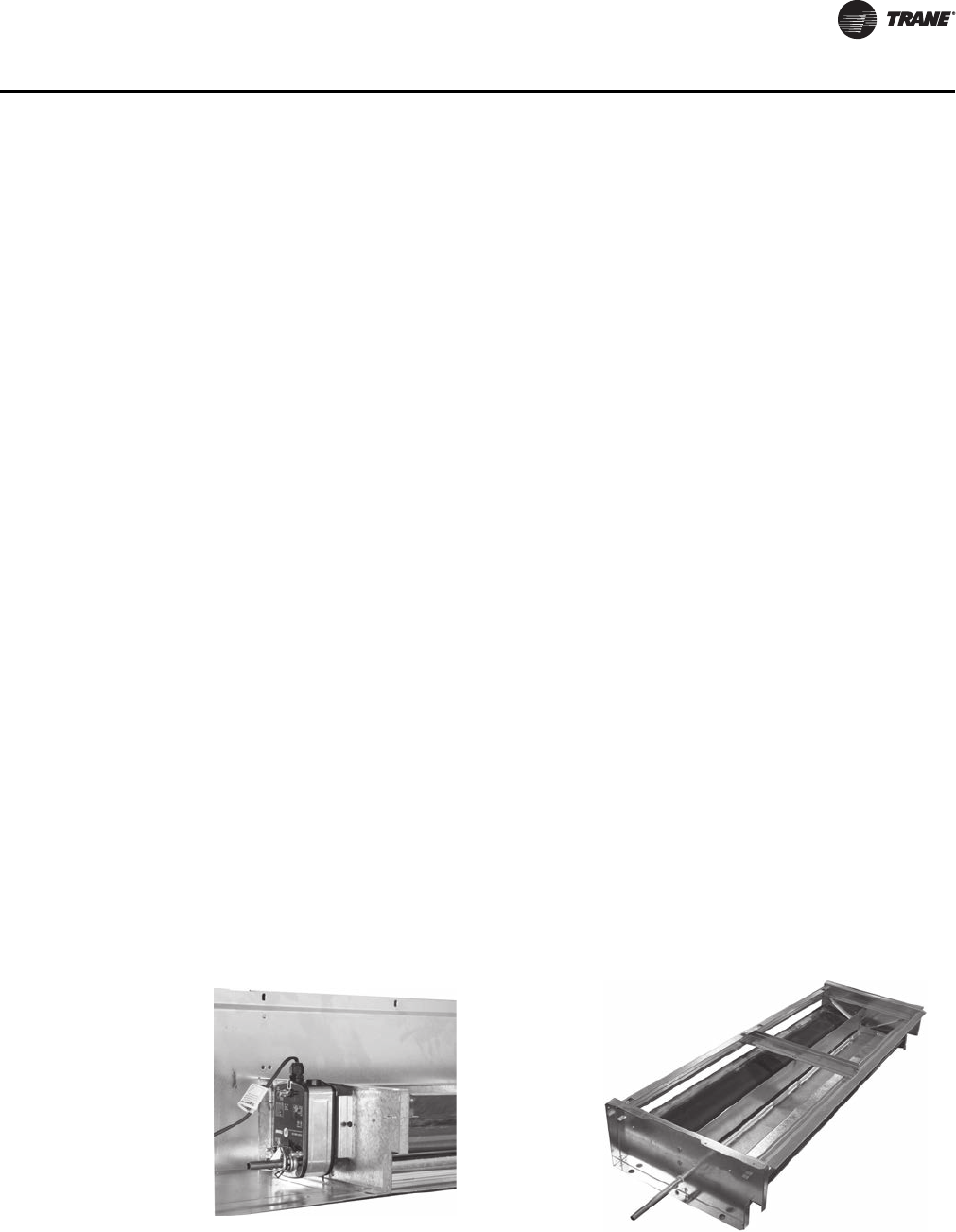
OA/RA Actuator
The OA/RA actuator provides true spring return operation for positive close-off of the OA/RA
damper. The spring return system of the actuator closes the outside damper if power is lost to the
building. When ordered with factory controls, the actuator is a 3-point floating design. A 2 to 10-Vdc
actuator is available when other than Trane controls are specified.
Figure 6. OA/RA Actuator and OA insulated damper
OA insulated damper
OA/RA actuator
UV-PRC003-EN.book Page 7 Tuesday, June 4, 2013 8:59 PM

8 UV-PRC003-EN
Features and Benefits
Unit Filter
Each classroom unit ventilator comes equipped with a standard-size throwaway filter to support
job site installation and start-up. However, the Trane unit ventilator is designed to accommodate
the use of a MERV 8 or MERV 13 high capacity filter to provide greater filtration of airborne
contaminants.
Dehumidification
Trane unit ventilators provide a broad range of dehumidification solutions. Active humidity control
involves monitoring and managing both the dry bulb temperature and the humidity in the
classroom. With this strategy, a reheat coil is placed downstream of the cooling coil to temper
(reheat) the cold, dehumidified air leaving the cooling coil to avoid over-cooling the space. Reheat
configurations are available in a variety of coil combinations.
Alternately, the Tracer™ UC400 or Tracer ZN520 controller can be configured to automatically
reduce the fan speed at part-load conditions. This helps improve the coincidental dehumidification
performance of the unit at part-load, and also lowers sound levels. To help ensure proper
ventilation in the classroom at lower fan speeds, the controller adjusts the outside air being
supplied to the classroom.
Economizer
One big advantage of a Unit Ventilator system is the ability to provide energy savings through an
economizer cycle. During mild seasons outside air is used to provide “free” cooling, thereby,
minimize or eliminate the need to run mechanical cooling equipment. To truly have an effective
economizer a Unit Ventilator must be able to bring in up to 100 percent of the design airflow
through the outside air damper opening. Trane Unit Ventilators are tested and certified to exceed
the industry standard, as defined by AHRI 840, for economizer effectiveness. This ensures the
school will realize the energy savings available through the economizer strategy.
Face and Bypass Actuator
The face and bypass damper actuator incorporates a direct couple design. It provides electronic
protection against overload. A limit switch is not included, nor required as part of the design. When
reaching the damper end position, the actuator automatically stops. The gears can be manually
disengaged with a button on the housing.
Acoustics
Quiet systems are extremely important in today’s classrooms. Trane offers many different system
solutions to balance the requirements of sound, cost, IAQ and efficiency. The Trane vertical unit
ventilator takes a comprehensive approach to delivering one of the quietest units available.
Fan and Blower Motor Assembly
Several innovative ideas have gone into the quiet design of the Trane vertical unit ventilator. The
fans diameters have been maximized to reduce the motor rpm and thus lower the noise, while still
maintaining the cfm requirements to support ventilation and capacity requirements. The unique
direct-drive fan and blower design diminishes vibration from occurring further ensuring quiet
operation.
Fan Speed Control
Trane provides the capability to vary airflow for suitable applications either with three speeds or
with a 0–10 Vdc input. This lowers the sound in the space and improves the dehumidification in the
cooling season at part-load. With field installed controls, this is accomplished with a unit-mounted
manual fan speed switch (allowing either 2- or 3-speed control) or variable speed control with a
0–10 Vdc input. ECM controls provide a soft ramp between speed changes—a significant
contributor to overall quiet operation.
UV-PRC003-EN.book Page 8 Tuesday, June 4, 2013 8:59 PM

UV-PRC003-EN 9
Features and Benefits
With the inclusion of the Tracer UC400 unit controller, the speed of the fan is infinitely varied
automatically in response to the load condition in the space. The controller also will adjust the
outside air being provided to properly ventilate the classroom at the lower airflow conditions.
Quiet Blow-Through Design
The Trane blow-through unit design enables additional sound attenuation by eliminating the fan
noise from entering the space directly. The position of the internal components is optimized to
enhance The performance and casing construction of Trane vertical unit ventilators further adds
to this acoustically superior design.
Certification/Standards
Comfort, energy and IAQ are all major issues that need to be woven into today’s school designs.
Therefore, it is important that designers of these systems have accurate information to make
system decisions. That is why the industry has developed performance standards and certification
programs which ensure that the equipment information provided to the design community is
correct and comparable across different manufacturers. The following list of certifications
identifies the commitment by Trane to providing the highest quality equipment and information to
our customers:
• AHRI-840
• ETL
• Tested in accordance to AHRI 350 (acoustics)
•L
ONMARK®
UV-PRC003-EN.book Page 9 Tuesday, June 4, 2013 8:59 PM

10 UV-PRC003-EN
Application Considerations
A Choice in System Design
The beauty of the classroom unit ventilator goes beyond its ability to heat and cool. The unit
ventilator design provides an opportunity to create a comfortable atmosphere for living, learning
and playing, while supporting energy efficiency savings. Some of the featured benefits of a unit
ventilator are:
• Individual room control.
• Fresh air ventilation and filtration.
• Individual dehumidification sequences per zone.
• Energy savings solutions through economizing functions and Electronically Commutated
Motors.
• A choice in heating/cooling applied systems.
• And, because the equipment is mounted directly in the living space, expense associated to
installed mechanical ductwork may be avoided.
Wide Variety of Heating/Cooling Coils
Trane’s unit ventilator offers a wide variety of coil configurations to be used in many design
considerations.
In environments where cooling needs are of main interest, a two-pipe coil coupled with a chiller,
or a direct expansion coil joined with a condensing unit may be used.
For heat specific applications, Trane offers a two-pipe hot water only unit to be combined with a
boiler. Electric heat and steam options are also available for heating selections.
When there is seasonal heating and cooling, a two-pipe chilled water/hot water changeover system
may be applicable to the mechanical design. This system requires a chiller and a boiler to support
the changeover necessity. However, where space constraints may present a concern, the Trane unit
ventilator may be equipped with a direct expansion coil for cooling, with an auxiliary electric heat
coil, hot water coil, or steam coil for heating.
Four-pipe chilled water/hot water systems are also available. This system is typically applied when
both heating and cooling may be simultaneously called for in the school.
Building Automation
As part of the building automation system, the mechanical HVAC system equipment may be
optimized to lower energy consumption. By running only the mechanical devices that are required
to support the building load at a given time of day or night, true energy consumption savings may
be achieved.
Maintenance and service information through the unit sensing devices are easily defined and
cured with an automated system.
With factory shipped direct digital controls, installation and start-up of the system are more simple.
Condensate
Proper condensate trapping is required for the classroom unit ventilator’s with hydronic and direct
expansion coils (steam coils do not require a trapped condensate setup). In a properly trapped
system, when condensate forms during normal operation, the water level in the trap rises until
there is a constant flow of water through the pipe. It is imperative to maintain water in the trap, and
not allow the trap to dry out during heating season.
Equipment should be installed level to avoid condensate build-up around the coil.
Performance
Application of this product should be within the catalogs airflow and unit performance. The Trane
Official Product Selection System (TOPSS™) will aid in the selection process for a set of given
UV-PRC003-EN.book Page 10 Tuesday, June 4, 2013 8:59 PM
UV-PRC003-EN 11
Application Considerations
conditions. If this program has not been made available, ask a local Trane account manager to
supply the desired selections or provide a copy of the program.
The Importance of Air Quality
Indoor air quality (IAQ) should be considered a top priority in the school environment. School
institutes contain a diverse day of activities that have a potential for air impurity sources including
cafeterias, art and science classrooms, vocational education areas, pools and locker rooms. Proper
ventilation and filtration of these spaces can pose some challenges.
Occupant density in classrooms is much higher than that found in office or retail spaces. The
amount of outdoor air required to ventilate a classroom is based predominantly on the number of
students expected to occupy the space. Students also move in large groups, frequently throughout
the building, resulting in widely varied thermal loads within the zones. To compound the situation,
a classroom mechanical system is typically run for 9 months of the year, and vacated for 3 months
(either by turning up or off the HVAC system). To increase the IAQ challenge even more, building
construction techniques that help reduce energy costs, also tightly seal the school. This can lead
to uncirculated/unfiltered air.
Ventilation
Ventilation is an important factor in the maintenance of healthy air. In a poor ventilated school
building, fumes and vapors are not properly exhausted allowing particles to develop. A healthier
building is a building where the air is exchanged more frequently and properly filtered. Through
ventilation, stale indoor air is exhausted and fresh treated outdoor air is drawn into the building.
The amount of ventilation air required is established by building codes and industry standards.
Most building codes reference ASHRAE Standard 62–Ventilation for Acceptable Indoor Air
Quality–as the minimum requirement for ventilation system design. Architects, engineers and
contractors utilize this standard when determining and calculating the type of load the building
environment will place on the mechanical system.
Trane Unit Ventilators Support Indoor Air Quality
The Trane unit ventilator is tested and designed to exceed ASHRAE Standard 62. This includes the
use of a higher efficiency filtration to help introduce proper levels of “fresh” diluted air for
contaminant removal.
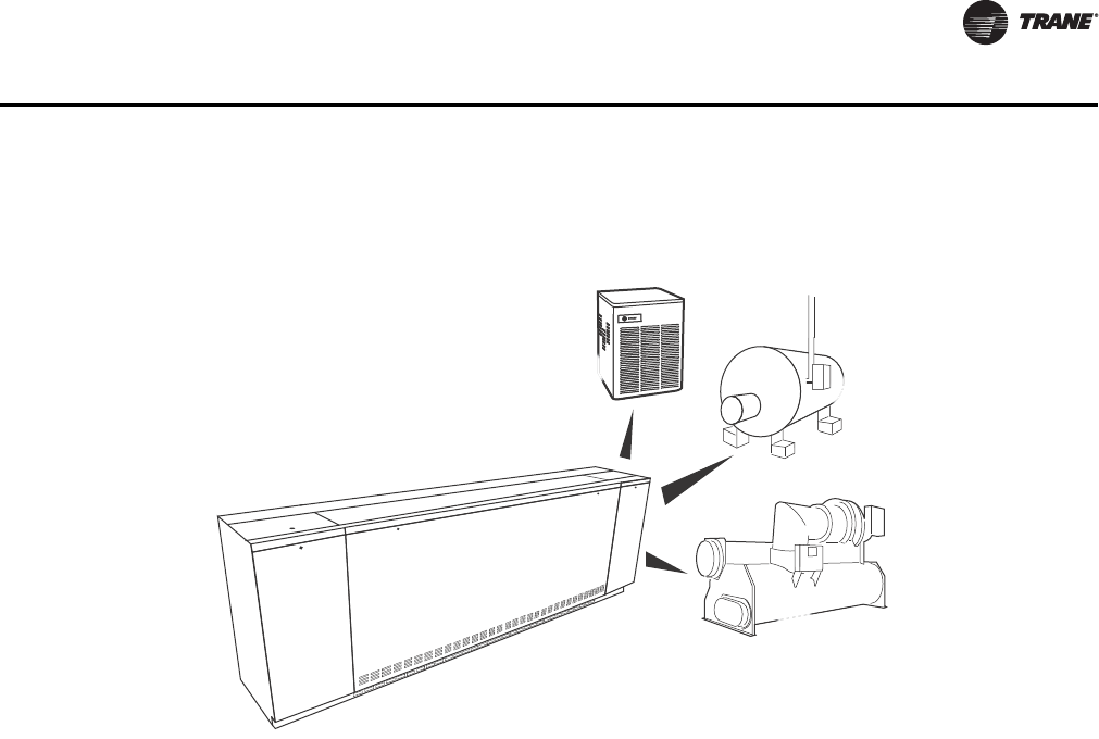
Figure 7. System choice for the classroom unit ventilator
AND/OR
AND/OR
CHILLER FOR
COOLING
BOILER
FOR HEAT ADD
CONDENSER
FOR COOLING
CLASSROOM UNIT VENTILATOR
Indoor Air Quality
UV-PRC003-EN.book Page 11 Tuesday, June 4, 2013 8:59 PM

12 UV-PRC003-EN
Application Considerations
Beyond the ventilation and filtration performance of the classroom unit ventilator, maintenance of
the HVAC system is a must. Several enhancements placed on the Trane unit ventilator to support
superior IAQ performance include:
• Coil presentation allows for ease of maintenance and cleaning.
• A dual sloped non-corrosive drain pan (removable) helps keep moisture in the system to a
minimum.
• Ultra low leak damper that results in a fixed air seal of the damper assembly.
• Air exchange performance that goes beyond code while maintaining the AHRI-840 certification
for economizing requirements.
• An upgrade-able MERV rated filters help reduce contaminants and increase filtration.
• Side-wall power exhaust support system to help remove the stale air from the classroom and
better support the air exchange.
• Energy recovery unit ventilator to further pretreat and dehumidify the fresh air before it enters
the classroom unit ventilator.
• Options for improved dehumidification at part-load, including automatic fan-speed control,
face and bypass dampers, and active humidity control through reheat.
A Choice in Energy Optimization
The energy consumption of a unit ventilator system can be significantly reduced through the use
of an economizer cycle. To better understand the basic function of how an outside air economizer
works, it is important to fully understand how it operates.
The economizer functions by opening an outside air damper, and bringing cooler outside air into
the space. The economizer cycle is controlled with a modulating damper motor, which opens at
specified increments dependent upon readings from outside air sensors.
Economizers also utilize a return-air damper that closes as the outside air damper opens.
Depending on the room requirements, the modulating damper motor may mix the return air with
the outside air to provide the maximum energy cost efficiencies without sacrificing comfort.
When the room thermostat calls for cooling, the economizer control provides the right mix of
outside and return air to cool the classroom. The equipment’s airflow is generated from both fan
energy and the economizing dampers. This design supports optimum ventilation and provides the
greatest energy savings. As the outside air temperature rises (typically above 55°F), the outside
damper closes to the minimum position, activating the second cooling stage on the room
thermostat—the cooling-generating device (compressor, water pump, chiller, cooling tower). The
return-air and outside air dampers modulate to support the discharged air temperature.
Dampers working together with the cooling coil is called integrated economizing, which allows a
unit ventilator to mix outside air with return air, delivering an energy-efficient, cost-savings
solution to a school.
Industry Standards
The Air-Conditioning, Heating, and Refrigeration Institute (AHRI) created the AHRI-840 standard for
classroom unit ventilators to provide a consistent method of rating the unit ventilators design
performance. To achieve AHRI-840 certification, the unit ventilator must be capable of providing a
minimum of 80 percent of its ventilation (airflow) through the outside air economizer function (see
Figure 8). This measurement ensures that the expected energy savings by the economizer is
realized in actual operation.
Only AHRI-840 certified equipment has been independently tested for compliance to the minimum
requirement. Trane was the first, and continues to be one of the few manufacturers that meet this
certification. By meeting this certification, the designer can be assured that the Trane unit ventilator
will perform with energy conservation in mind.
Energy Efficiency
UV-PRC003-EN.book Page 12 Tuesday, June 4, 2013 8:59 PM
UV-PRC003-EN 13
Application Considerations
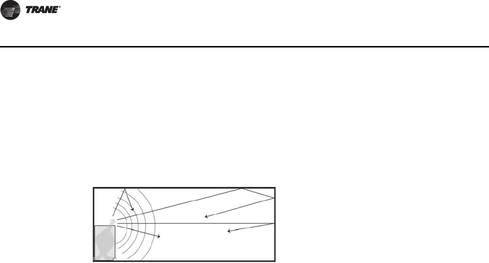
Acoustics
A growing population, and an increase in economic pressure to maximize building footprints have
resulted in higher building occupancies and less space to place the HVAC equipment. Often times
the close proximity of the equipment—such as a floor mounted unit ventilator—may cause noise
related complaints. Reducing the likelihood of these complaints requires careful planning:
• In the equipment sizing (under sizing and over sizing could increase noise level).
• And equipment placement (absorption and number of sound sources in the room greatly affect
noise).
Room NC is the sum of all sounds entering the room. Its value is based on assumptions about the
room’s characteristics. Given the complexity of various building systems, it is extremely important
to assure that the design goals (commissioning) for classroom acoustics, IAQ, and moisture control
are met through all aspects of the space.
For example, it is not uncommon for a school to install unit ventilators that are manufacturer-rated
for a specified airflow (cfm), but which are not AHRI-840 certified. These units may ship with a fan-
speed setting that delivers a lower than specified airflow, perhaps to reduce sound levels. Without
an overall building design goal, these units will be installed without delivering the specified airflow
needed to support the fresh air circulation, and possibly compromise IAQ.
Note: Unless the equipment is tested at the specified airflow, it is extremely difficult to determine
whether the unit meets the specified sound level.
Trane’s unit ventilator will not compromise air quality to support a minor reduction in airflow noise.
We encourage our engineers to specify their airflow needs at full building load requirements. Fine-
tuning of the speed setting may be interchanged through the unit’s 3-speed fan sensor quickly and
easily. This mechanical feature ensures that the equipment supplies proper cfm to support IAQ in
the classroom, while giving complete control of equipment noise to the administrative staff.
Technology that Supports Acoustic Enhancements
Another solution to airflow noise is through Trane direct digital controls (Tracer UC400). With the
Tracer UC400 controller, an infinitely variable speed fan control for the unit ventilator delivers the
airflow output customized to support the cfm space needs. When less cfm is necessary to meet the
Figure 8. Unit ventilator economizer
Acoustics
UV-PRC003-EN.book Page 13 Tuesday, June 4, 2013 8:59 PM
14 UV-PRC003-EN
Application Considerations
load of the classroom, the equipment operates at an optimum speed, keeping sound levels to a
minimum. Another solution for acoustically sensitive application is the option for “Low Acoustics,”
which uses the ECM technology to manage the fan speeds. However, if the room temperature rises
above the setpoint, the controller will switch to high speed for sustaining the space needs. As part
of this strategy, ventilation must also be considered. The Tracer UC400 controller will reposition
the outside air damper to confirm the minimum outside air cfm is met at both operating conditions.
This setup allows the unit ventilator to meet the space comfort condition, while providing a lower
sound level and proper ventilation.
Ventilation for Acceptable IAQ
Supplying proper ventilation to a classroom is challenging. The various rooms that make up a
school are forever changing in their proper ventilation needs. Building occupants and their
activities generate pollutants that heighten the ventilation requirements. And because of this
intermittent occupancy, the ventilation frequency of a classroom is constantly on the move.
Ventilation systems dilute and remove indoor contaminants, while mechanical heating and cooling
systems control the indoor temperature and humidity. Supplying an adequate amount of fresh air
to an occupied classroom is necessary for good indoor air quality. IAQ should be considered a top
priority in the school environment because children are still developing physically and are more
likely to suffer the consequences of indoor pollutants. For this reason, air quality in schools is of
particular concern. Proper conditioning of the indoor air is more than a quality issue; it
encompasses the safety and stewardship of our investment in the students, staff and facility.The
beauty of a classroom unit ventilator is its ability to provide heating, cooling, ventilation and
dehumidification as a single-zone system.
ASHRAE Control Cycles
There is a variety of control systems available today in unit ventilators. The exact method of
controlling the amount of outside air and heating capacity can vary. However, all systems provide
a sequence of operation designed to provide rapid classroom warm-up and increasing amount of
ventilation air to offset classroom load.
To help supply proper ventilation to these fluctuating heat gains, the Trane unit ventilator is
designed to provide rapid classroom warm-up and increasing amounts of ventilation air to offset
classroom overheating.
Figure 9. Equipment placement
Ventilation
UV-PRC003-EN.book Page 14 Tuesday, June 4, 2013 8:59 PM
UV-PRC003-EN 15
Application Considerations
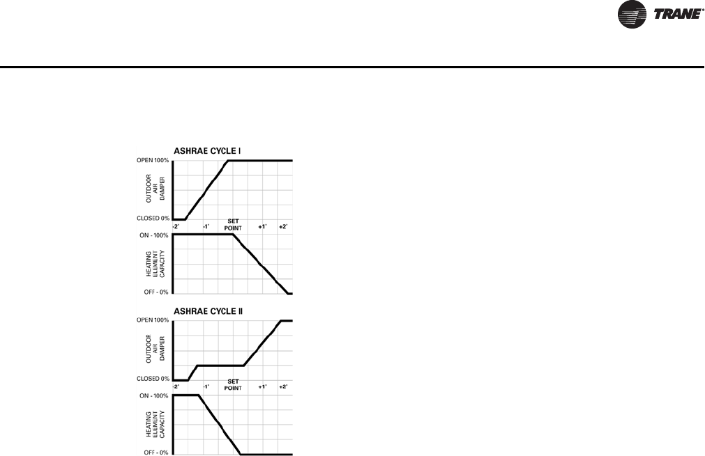
ASHRAE Cycle I
All standard unit ventilator cycles automatically close the outside air damper whenever maximum
heating capacity is required. As room temperature approaches the comfort setpoint, the outside
air damper opens fully, and the unit handles 100 percent outside air. Unit capacity is then controlled
by modulating the heating element capacity.
ASHRAE Cycle I is typically used in areas where a large quantity of outdoor air is required to offset
the air being exhausted to relieve the room of unpleasant odors and particles.
ASHRAE Cycle II
ASHRAE Cycle II is the most widely used ventilation control. Similar to Cycle I, the outside air
damper is closed during warm-up. But with Cycle II, the unit handles recirculated air through the
return air system. As temperature approaches the comfort setting, the outside air damper opens
to admit a predetermined minimum amount of outside air. This minimum has been established by
local code requirements and good engineering practices. Unit capacity is controlled by varying the
heating output. If room temperature rises above the comfort setting, the heating is turned off and
an increasing amount of outside air is admitted until only outside air is being delivered.
ASHRAE Cycle II is a very economical control sequence often referred to as integrated
economizing. This design supports optimum ventilation and provides the greatest energy savings.
This is further proof of why AHRI-840 certification is important in minimizing energy consumption
through economizer performance.
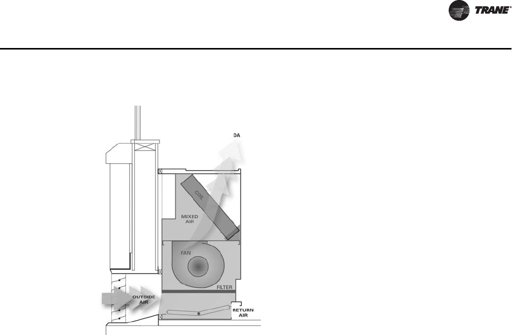
Freeze Protection
The most important advantage the Trane blow-through design provides is additional protection
against coil freeze-up. In contrast, draw-through configurations allow little mixing of the return and
outside air stream while locating the coil very close to the outside air inlet. This process creates
“cold spots” on the coil which could lead to coil freeze-up.
With a blow-through design, face and bypass with isolation valve control is not necessary to
provide proper freeze protection to the unit vent. The placement of the coil above the fan allows
enough space for the coil to avoid “cold spots” that could cause freezing.
Figure 10. ASHRAE Cycle graph
Ventilation
UV-PRC003-EN.book Page 15 Tuesday, June 4, 2013 8:59 PM
16 UV-PRC003-EN
Application Considerations
Constant Volume System
A typical unit ventilator is a constant-volume, variable-temperature device. It uses a constant fan
speed and modulates water flow through a chilled water coil to maintain the dry bulb temperature
in the space based off of a setpoint. Outdoor air is introduced at the back of the unit ventilator, and
distributed with the supply air. At design cooling load conditions, a system controlled in this
manner typically has a leaving air temperature that is cold enough (and, therefore dry enough) to
sufficiently dehumidify the space, but its ability to dehumidify can decrease significantly at part-
load conditions.
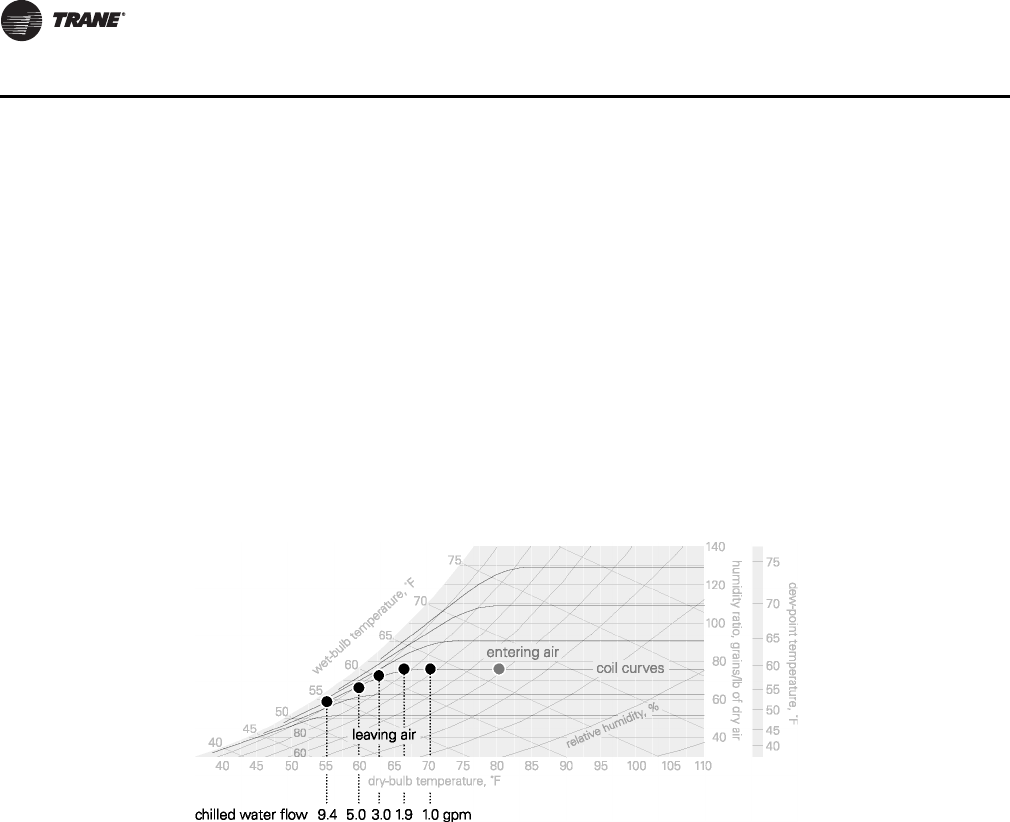
When the sensible load in the space decreases (part-load), the constant-volume system responds
by raising the dry-bulb temperature of the supply air. In a chilled water unit ventilator, this is
accomplished by modulating a valve to reduce the rate at which water flows through the coil.
Figure 11 shows how this affects the supply air leaving the coil—the warmer coil surface that results
from less water flow provides less sensible cooling (raising the supply air temperature) and
removes less moisture from the passing air stream.
The sensible cooling capacity of a constant volume system decreases to match the smaller sensible
cooling load. Any latent cooling (dehumidification) capacity is purely coincidental, whether the
cooling-coil medium is chilled water or refrigerant. As the load diminishes, the system delivers
even warmer supply air. Some dehumidification can occur in this situation, but only if the sensible
load is high enough.
Some designers attack this problem by oversizing the unit ventilators. This does not solve the
problem; in fact, it can make the situation worse. Increasing the capacity of the unit ventilator may
also require increasing the supply airflow. A higher-than-necessary supply airflow results in
warmer supply air and, in non arid climates, less dehumidification. It’s important to understand,
this is not just a unit, coil, or fan-sizing challenge. Rather, it’s an issue of properly controlling the
system in a manner provides sufficient dehumidification at all operating conditions. Proper
dehumidification with terminal units is a matter of proper control.
Active Humidity Control
A common method used to address this part-load humidity control challenge in a constant-volume
system is active humidity control through supply air tempering (reheat). Active humidity control
involves monitoring and controlling both the dry bulb temperature and humidity in the occupied
space. Whenever the space humidity is below the preset upper limit (typically 60 percent relative
humidity), the system operates just like a normal constant-volume system. However, if the space
humidity reaches or exceeds the upper limit, the cooling coil control valve is driven open regardless
of the need for sensible cooling in the space. The coil over-cools the air, increasing the
dehumidification capacity of the system.
With this control sequence, a reheat coil is placed downstream of the cooling coil to temper (reheat)
the cold, dry air leaving the cooling coil in order to avoid over-cooling the space. The key to cost-
Figure 11. Part-load dehumidification with modulated chilled water
Dehumidification
UV-PRC003-EN.book Page 16 Tuesday, June 4, 2013 8:59 PM

UV-PRC003-EN 17
Application Considerations
effectively applying an active humidity control system is to use reheat only when it is needed. This
requires the sensing of both the humidity and temperature in the occupied space.
When the space humidity falls below the upper limit, the system returns to the standard cooling
mode and again operates as a traditional constant-volume system.
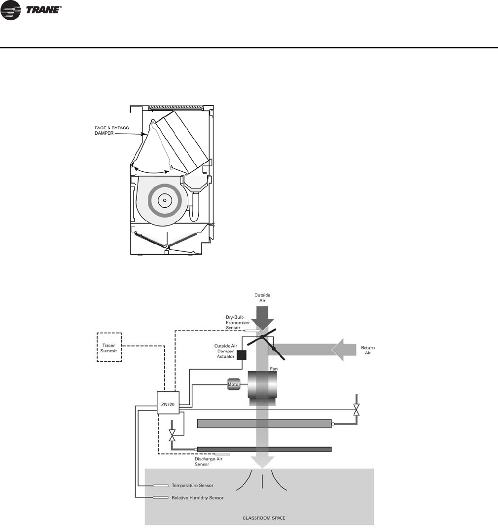
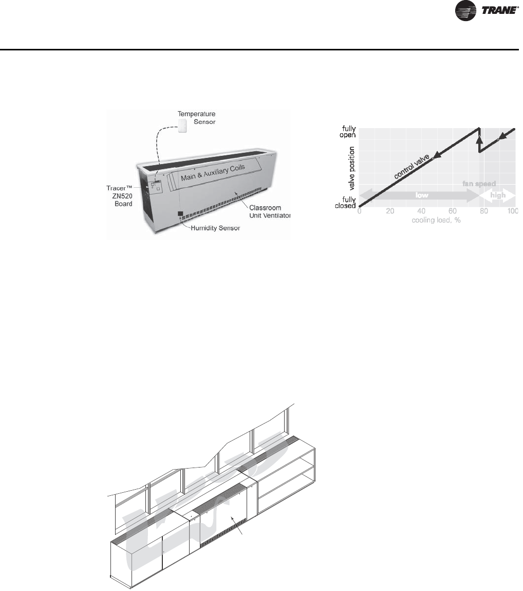
Basic components of Trane’s reheat system, include a (1) classroom unit ventilator with a main
coil and an auxiliary coil downstream, (2) the Tracer ZN520 digital controller, and (3) two
sensors, one for the temperature and one for relative humidity. Sensors may be located in the
zone, or in the return air stream.
If after hours operation is required, the addition of a building automation system (BAS) such as
Tracer Summit™ is recommended to coordinate the chillers, pumps, boiler and unit ventilators. It
also assures proper operation of the exhaust fans.
Reheat may come from new energy (electric resistance heat or boilers fueled by gas or oil) or
recovered energy.
Recovered energy reheat refers to the process of salvaging or transferring energy from another
process within the facility. In this case, the recovered energy is the by-product of a cooling process
which would normally be rejected or wasted. A common example may include a plate and frame
heat exchanger in the condenser water loop of a water-cooled chiller system.
Automatic Fan-Speed Adjustment
Reducing the fan speed (supply airflow) at part-load conditions is a way to improve the coincidental
dehumidification performance of a unit ventilator. The Tracer ZN520 digital controller can be
configured to automatically reduce fan speed when the sensible load is decreased, Figure 12, p. 18.
At full load, the fan operates at high speed and the control valve’s flow is wide open. As the cooling
load decreases, the controller modulates the valve to throttle the rate of chilled water flow through
the coil. At some point, based on valve position, the unit controller switches the fan to low speed.
Less airflow means that colder supply air is needed to maintain the target space temperature. The
control valve opens allowing the coil to remove more moisture from the passing air stream.
The controller will also adjust the outside air damper to help properly ventilate the classroom at
the lower fan speed condition.
Face and Bypass Dampers
Face and bypass control is a common and accepted method of capacity control.
The face and bypass damper, consists of a single blade installed immediately upstream of the
cooling coil. The bypass is sized to have the same pressure drop as the cooling coil so that a
constant air quantity can be maintained at all times during system operation.
Bypass control maintains the dry bulb temperature in the space by modulating the amount of air
flowing through the cooling coil, thus varying the supply air temperature to the space. As the face
and bypass damper begins to close some of the outside/return air mix is diverted around the coil
and mixed with air coming off the coil to obtain a supply air temperature that is proportional to the
reduction in space load. Because the chilled water valve remains wide open, the portion of the air
passing through the coil is dehumidified further, improving part-load dehumidification.
However, face and pass control does not actively control space humidity. It still allows the space
humidity level to rise at part-load, often higher than desired.
For more information on various methods for improving dehumidification performance of unit
ventilator systems, refer to Trane “Dehumidification in HVAC Systems” application manual
SYS-APM004-EN.
Dehumidification
UV-PRC003-EN.book Page 17 Tuesday, June 4, 2013 8:59 PM
18 UV-PRC003-EN
Application Considerations
Figure 12. Face and bypass damper
Figure 13. Basic components of active dehumidification control
Dehumidification
UV-PRC003-EN.book Page 18 Tuesday, June 4, 2013 8:59 PM
UV-PRC003-EN 19
Application Considerations
Dynamic Air Barrier
In areas that contend with colder climates for a significant period of time, a school may wish to
employ a dynamic air barrier package. With this dynamic (draft) barrier system, the cold air is
captured off of the window, and drawn into the classroom unit ventilator’s normal airflow cycle.
The unit ventilator treats/warms the air as if it were part of a return-air makeup system. This
captured air is then discharged into the space providing comfort to the classroom’s occupants.
This draft barrier shield should be utilized when:
• Almost 50 percent of the wall includes windows.
• Outside air temperatures fall below 35°F for a significant period of time
• Or, in retrofit applications where the windows are of a single pane thickness.
Outdoor Air Preconditioning
Conditioning the large amounts of outdoor air required for proper classroom ventilation can
significantly increase building cooling and heating loads. It also raises the system’s first cost and
operating cost. One way to reduce the impact of the outdoor air load on the unit ventilator is to use
energy recovered from the exhaust air stream to precondition the outdoor air as it’s brought into
the building.
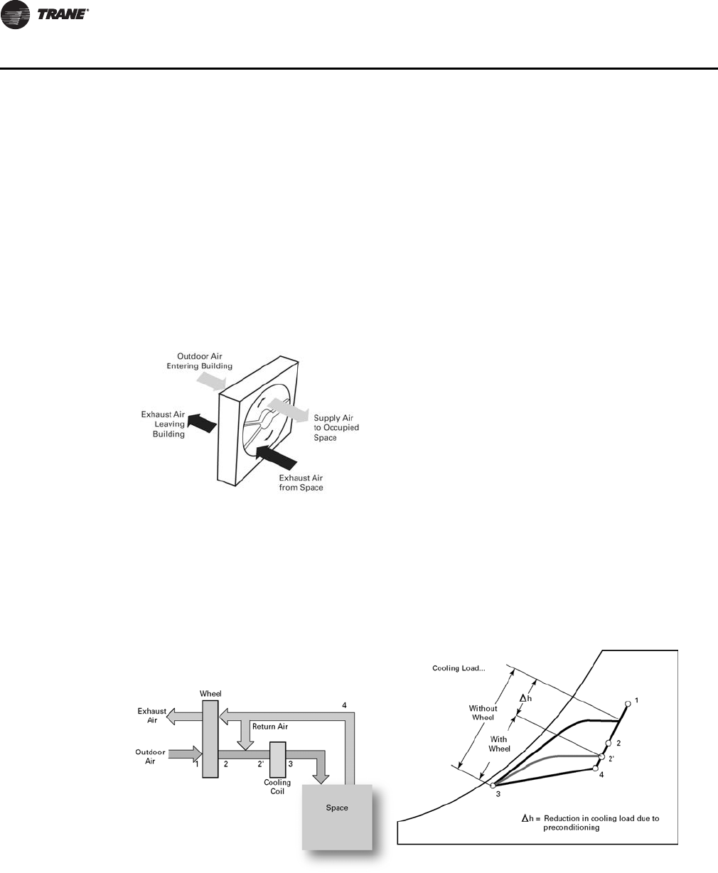
A total-energy recovery (enthalpy) wheel consists of a revolving cylinder filled with a desiccant-
coated medium suitable for sensible and latent (moisture) heat transfer, Figure 16, p. 20. The
Figure 14. Reheat system and auto fan speed adjustment
Auto Fan Speed Adjustment with Tracer ZN520
Reheat System
Figure 15. Dynamic air barrier
Unit Ventilator
Captured
Cold Air
Draft Barrier and OA Preconditioning
UV-PRC003-EN.book Page 19 Tuesday, June 4, 2013 8:59 PM
20 UV-PRC003-EN
Application Considerations
adjacent outdoor and exhaust air streams pass through the wheel in a counterflow arrangement
that transfers energy from one air stream to the other.
During the cooling season, the drier, sensible heat and moisture transfer from the outdoor air to
the cooler, drier exhaust air. Conversely, during the heating season, sensible heat and moisture
transfers from the exhaust air to preheat and humidify the entering outdoor air stream. Figure 16
psychrometric ally depicts the impact of a preconditioning total-energy wheel on a unit ventilator.
This approach can’t directly control humidity in the space, but it can significantly reduce the
capacity (and operating cost) of the cooling and heating equipment required to condition the
outdoor air. Capable of recovering 65 to 75 percent of the energy in the exhaust air stream, total-
energy wheels used in conjunction with unit ventilators can be an attractive alternative when
upgrading existing classroom to meet ASHRAE’s ventilation requirements; they reduce, perhaps
even eliminate, the extra capacity needed at the chiller plant or boiler.
The Trane ERS energy recovery unit ventilator is one example of a “cold coil” unit with outdoor
air preconditioning.
Note: Both preconditioning (energy recovery) and post conditioning (reheat) may be applied in
the same system.
For more information on outdoor-air preconditioning and energy recovery, refer to the Trane
application engineering manual, Air-to-Air Energy Recovery in HVAC Systems (SYS-APM003-EN).
Figure 16. Energy recover wheel
Figure 17. Cold coil with outdoor air preconditioning
Draft Barrier and OA Preconditioning
UV-PRC003-EN.book Page 20 Tuesday, June 4, 2013 8:59 PM

UV-PRC003-EN 21
Selection Procedure
Trane vertical classroom unit ventilators provide air delivery and capacities necessary to meet the
requirements of modern school classrooms. They are available with the industry’s widest selection
of coils to precisely satisfy heating, ventilating and air conditioning loads with the best individual
type of system. Unit ventilator selection involves three basic steps.
• Determine the classroom/space unit cooling and/or heating loads
• Determine the unit size
• Select the coil
Capacity Required
The first step in unit ventilator selection is to determine room heating and air conditioning loads.
The calculation of this load is essential if the equipment is to be economical in first cost and
operating cost.
Adequate ventilation is mandatory in classroom air conditioning design. The amount is often
specified by local or state codes and, in air conditioned schools, may be either the same or less than
that specified for heating systems. The usual requirement is between 15 and 25 cfm of outside air
per occupant, based on the intended use of the room. For instance, a chemistry laboratory normally
requires more ventilation for odor control than a low occupancy speech clinic.
Ventilation is an important concern and should be accurately determined to assure good indoor air
quality. Purposely oversizing units should be avoided, since it can cause comfort and control
issues.
Unit Size
Unit ventilator size is determined by three factors:
• Total air circulation
• Ventilation cooling economizer capacity required
• Total cooling or heating capacity required
Total air circulation, if not specified by code, should be sufficient to ensure comfort conditions
throughout the room. This is usually from six to nine air changes per hour, but can vary with room
design and exposure. Often rooms with large sun exposure require additional circulation to avoid
hot spots.
Ventilation cooling capacity is determined by the amount of outside air delivered with the outside
air damper fully open, and the temperature difference between the outside air and the classroom.
In air conditioning applications, ventilation cooling capacities should maintain the comfort setting
in the classroom whenever the outside air temperature is below the unit or system changeover
temperature.
UV-PRC003-EN.book Page 21 Tuesday, June 4, 2013 8:59 PM
22 UV-PRC003-EN
Selection Procedure
Example:
Ventilation cooling capacity = 1.085 x cfmt x (T1 - T2)
cfmt = Total air capacity of unit with outside air damper open 100 percent.
T1 = Room temperature.
T2 = Outside air temperature.
In classrooms with exceptionally heavy air conditioning loads, unit size may be determined by the
total cooling requirement. Good practice dictates 375 to 425 cfm per ton of hydronic cooling
capacity. Normally, however, Trane classroom air conditioner coils have sufficient capacities.
Example:
Given: Air circulation specified = 8 air changes per hour.
Classroom size = 35 ft long x 25 ft wide x 10 ft high
Inside design air temperature = 75 degrees F
Ventilation cooling required at 58 degrees F = 29,000 BTU
Checking ventilation cooling capacity:
29,800 BTU = 1.085 x CFM x (80-58)
CFM = 1250
This indicates that a 1250 cfm unit would have satisfactory ventilation cooling capacity at the
design changeover point of 58°F. Coil capacity will become confirmed when the coil is selected.
Coil Selection
Selecting the correct coil is done through Trane’s Official Product Selection System (TOPSS) For
your convenience, TOPSS has a mixed air calculator built into the program.
CFM required =
8 changes/hr x (35 x 25 x 10)ft3
= 1170 cfm
60 Minutes/hr
UV-PRC003-EN.book Page 22 Tuesday, June 4, 2013 8:59 PM

UV-PRC003-EN 23
Vertical Unit Ventilator
Model Number
Digits 1, 2, 3 — Unit
Configuration
VUV= Vertical Unit Ventilator
Digit 4 — Development
Sequence
E
Digits 5, 6, 7 — Nominal Airflow
075 = 750 cfm
100 = 1000 cfm
125 = 1250 cfm
150 = 1500 cfm
Digit 8 — Voltage (Volts/Hz/
Phase)
0 = 115/60/1
1 = 208/60/1
2 = 230/60/1
3 = 208/60/3
4 = 460/60/3
7 = 277/60/1
8 = 230/60/3
Digit 9 — Open Digit
Digits 10, 11 — Current Design
Sequence
Digit 12 — Face & Bypass
Y = Yes, Include Damper
N= No Damper
Digit 13 — Unit Arrangement
1 = Return Air Front / Fresh Air Back
2 = 100% Return Air Front
3 = 100% Fresh Air Back
4 = Dynamic Air Barrier
5 = ERS-Compatible w/RH
Connection
6 = ERS-Compatible w/LH Connection
Digit 14 — Preheat / Reheat /
Changeover
A = 4-Pipe Preheat (RH Clg/LH Htg)
B = 4-Pipe Preheat (LH Clg/RH Htg)
C = 4-Pipe Reheat (RH Clg/LH Htg)
D = 4-Pipe Reheat (LH Clg/RH Htg)
E = 2-Pipe (RH Connections)
F = 2-Pipe (LH Connections)
Digit 15 — Cooling / 2-Pipe Coil
0=None
B = 2-Row, 12 F.P.I.
C = 2-Row, 16 F.P.I.
D = 3-Row, 12 F.P.I.
E = 3-Row, 16 F.P.I.
F = 4-Row, 12 F.P.I.
G = 4-Row, 14 F.P.I.
H = 3-Row, 16 F.P.I, EarthWise™ Coil
J = 3-Row, DX (R-410A) Cooling Coil
Digit 16 — Heating Coil
0=None
A = 1-Row, 12 F.P.I.
B = 2-Row, 12 F.P.I.
C = 2-Row, 16 F.P.I.
D = 3-Row, 12 F.P.I.
E = 3-Row, 16 F.P.I.
F = 4-Row, 12 F.P.I.
G = 4-Row, 14 F.P.I.
H = 3-Row, 16 F.P.I, EarthWise Coil
K=Steam Low
L=Steam High
M = Electric Heat - Low
N = Electric Heat - Med
P = Electric Heat - High
Digit 17 — Motor
0 = Electronically Commutated Motor
(ECM)
1 = ECM & Low Acoustic Option
2 = ECM & Low FLA Option
3 = ECM & Low Acoustic & Low FLA
Option
Digit 18 — Other Motor Items
A= None
B = Toggle
C = Circuit Breaker
Digit 19 — 2- or 3-Way Valve -
Cooling Changeover Coil
0=None
2 = 2-Way; 3-Point Floating
3 = 3-Way; 3-Point Floating
4 = 2-Way; 2–10 Volt
5 = 3-Way; 2–10 Volt
6 = Isolation Valve; 2-Way
7 = Isolation Valve; 3-Way
Digit 20 — CV - Cooling or
Changeover Coil
0=None
L=Low Cv
M= Medium Cv
H= High Cv
Digit 21 — 2- or 3-Way Valve -
Preheat or Reheat Heating Coil
0=None
2 = 2-Way; 3-Point Floating
3 = 3-Way; 3-Point Floating
4 = 2-Way; 2–10 Volt
5 = 3-Way; 2–10 Volt
6 = Isolation Valve; 2-Way
7 = Isolation Valve; 3-Way
Digit 22 — CV - Preheat or
Reheat Heating Coil
0=None
L=Low Cv
M= Medium Cv
H= High Cv
Digit 23 — Discharge
Arrangement
0 = Opening Only, No Grille
A = Discharge Grille
B = Double Deflection Discharge
Grille
C = Grille Discharge with Wire Mesh
Digit 24 — Outside Air Damper
Control
0=None
A = 3-Wire Actuator
B = 2–10 Volt Actuator
Digit 25 — Face and Bypass
Damper Control
0=None
A = 3-Wire Actuator
B = 2–10 Volt Actuator
Digit 26 — Controls
0 = None, Unit-Mounted Speed
Switch
2 = Customer Supplied Terminal
Interface (CSTI)
3 = CSTI w/Low Temp Detection
4 = Tracer ZN520
5 = Tracer ZN520 w/Time Clock
6 = Tracer ZN520 with w/Fan Status
7 = Tracer UC400
8 = Tracer UC400 w/Time Clock
Digit 27 — Unit- or Wall-Mounted
Controls
0=None
1 = Unit-Mounted
2 = Wall-Mounted
3 = Unit-Mounted Fan Speed
Switch & Wall-Mounted
Temperature Sensor
4 = Wireless Zone Sensor
Note: The wall-mounted room sensor is
ordered as separate line item.
Digit 28 — Internal or External
Set Point
0=None
2=External
3 = Digital Display
Digit 29 — Timed Override
0=No
1=Yes
Digit 30 — Exhaust Control
A = No Exhaust Control with 3-Speed
Supply Fan
B = Exhaust Control with 2-Speed
Supply Fan
Digit 31 — Control Programming
(Sensor Included)
0=None
1 = Humidity Sensor Programming
2=CO
2 Sensor Programming
Model Number Descriptions
UV-PRC003-EN.book Page 23 Tuesday, June 4, 2013 8:59 PM

24 UV-PRC003-EN
Model Number Descriptions
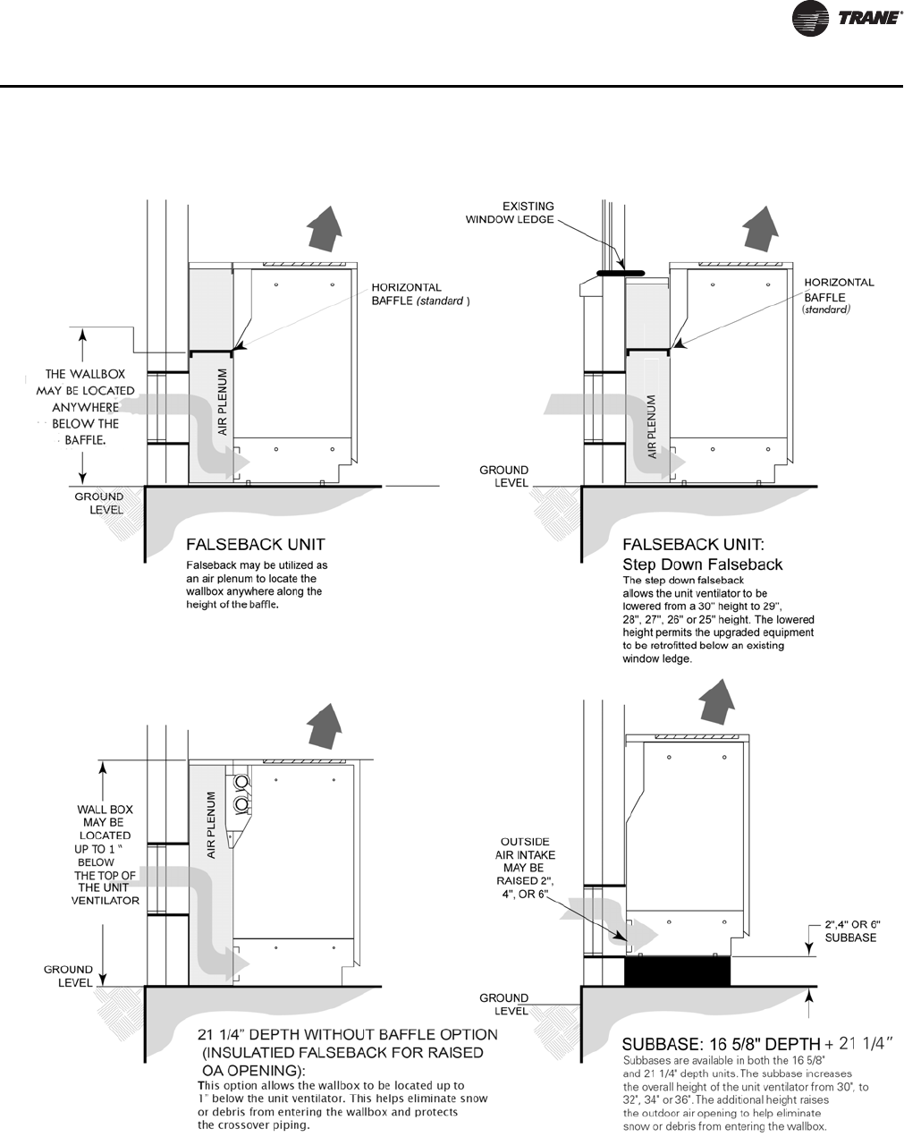
Digit 32 — Unit Depth
A = Standard (16-5/8 in.)
B = 21-1/4 in. Depth with Baffle
C = 21-1/4 in. Depth with Full Sheet
Metal Back and Baffle
D = 21-1/4 in. Depth with 25 in. High
Falseback
E = 21-1/4 in. Depth with 26 in. High
Falseback
F = 21-1/4 in. Depth with 27 in. High
Falseback
G = 21-1/4 in. Depth with 28 in. High
Falseback
H = 21-1/4 in. Depth with 29 in. High
Falseback
J = 21-1/4 in. Depth without Baffle
Note: Selection “J” should be applied if
OA opening is raised above
standard baffle location.
Digit 33 — End Covers
0=None
1 = 16-5/8 in. Depth without Cutouts
2 = 16-5/8 in. Depth with 3 x 7-1/4 in.
Cutout
4 = 21-1/4 in. Depth without Cutouts
5 = 21-1/4 in. Depth with 3 x 7-1/4 in.
Cutout
6 = 21-1/4 in. Depth with 3-1/4 in. x
16-7/8 in. Cutout
Digit 34 — Front Panel
1 = Standard Front Panel
2 = Heavy Gauge Front Panel
Digit 35 — Subbase
0=No Subbase
2 = 2 in. Subbase
4 = 4 in. Subbase
6 = 6 in. Subbase
Digit 36 — Piping Package
0=None
1 = Ball Valves & P/T Ports
2 = Ball Valve & Circuit-Setter with
P/T Ports
3 = Ball Valve, Circuit-Setter with
P/T Ports & Strainer
Digit 37 — Flow Control -
Cooling/Changeover Coil
0=None
Digit 38 — Flow Controls -
Heating Coil
0=None
Digit 39 — Auxiliary Drain Pan -
Piping
Y = Yes, Auxiliary Drain Pan
N = No Auxiliary Drain Pan
Digit 40 — Crossover Piping
0=None
1=Internal
2 = External 1-3/8 in. Crossover
Piping
3 = External 2-1/8 in. Crossover
Piping
Digit 41 — Filter
1 = Standard Throwaway Filter
2 = MERV 8 Filter
3 = MERV 13 Filter
Digit 42 — Color
1 = Deluxe Beige
2 = Cameo White
3=Soft Dove
4 = Stone Gray
5 = Driftwood Gray
UV-PRC003-EN.book Page 24 Tuesday, June 4, 2013 8:59 PM
UV-PRC003-EN 25
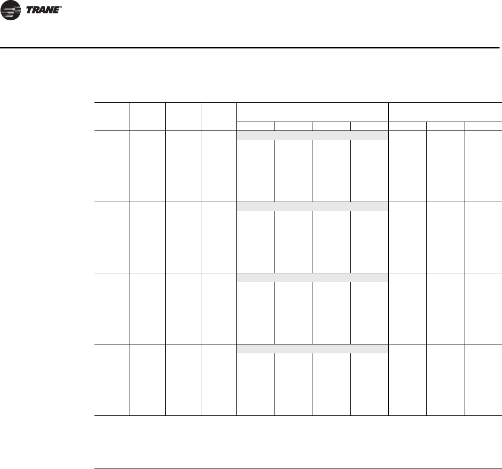
General Data
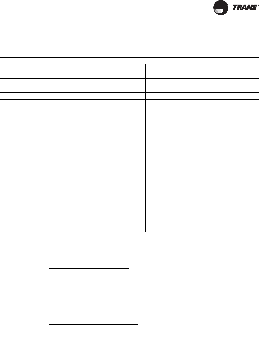
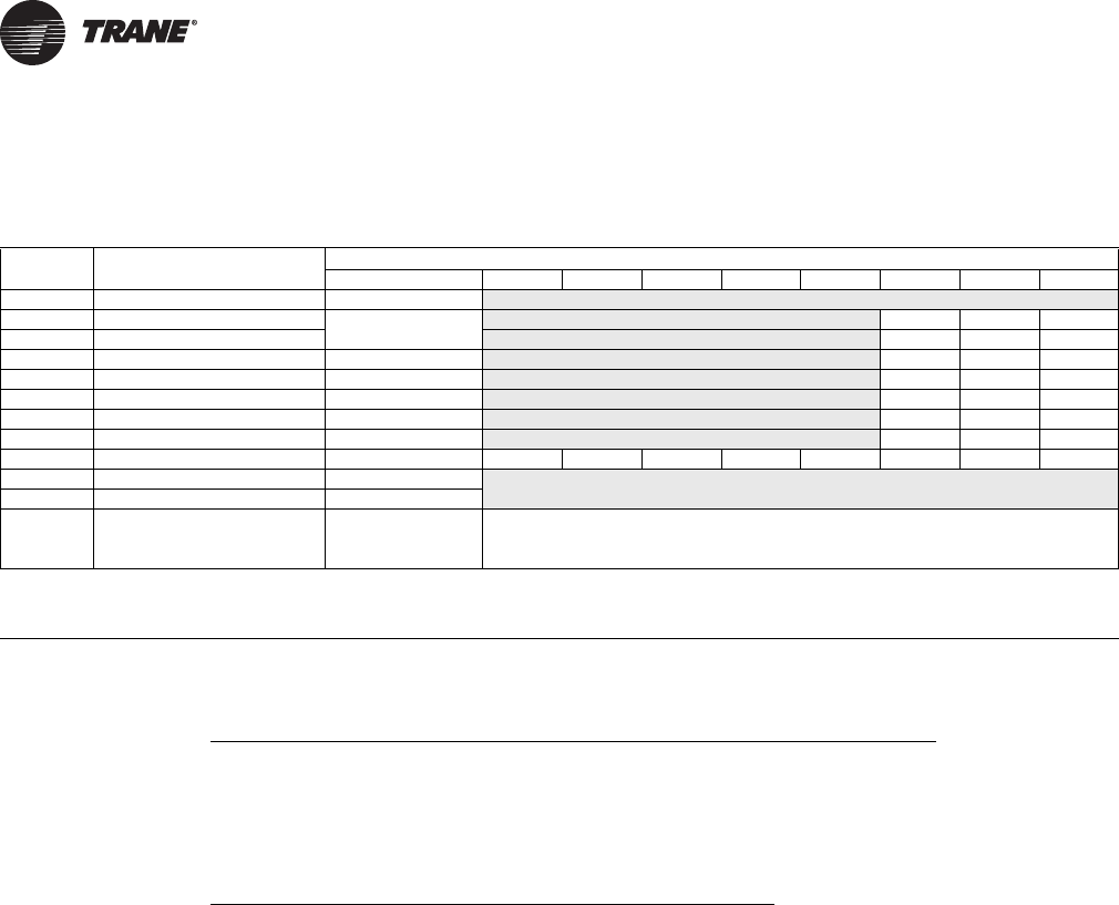
Table 1. General data
Description
Unit size
0750 1000 1250 1500
Unit length without end covers (in.) 69 81 93 105
Unit depth—standard (in.) 16-5/8 16-5/8 16-5/8 16-5/8
Unit depth—with false back (in.) 21-1/4 21-1/4 21-1/4 21-1/4
Unit height—standard (in.) 30 30 30 30
Shipping weight (lb) 320 405 450 470
Nominal filter size (in.) and 14 x 20 x 1 (2) 14 x 24 x 1 (1) 14 x 20 x 1 (2) 14 x 24 x 1 (2)
quantity 14 x 30 x 1 (1) 14 x 24 x 1 (1) 14 x 30 x 1 (1)
Dynamic air filter nominal 7 x 42 x 1 (1) 7 x 54 x 1 (1) 7 x 66 x 1 (1) 7 x 78 x 1 (1)
size (in.) and quantity
Drain connection size (in.) 7/8 ID Hose 7/8 ID Hose 7/8 ID Hose 7/8 ID Hose
Fan type / quantity FC / 2 FC / 2 FC / 4 FC / 4
Motor data
Quantity 1122
Horsepower (ea.) 1/4 1/4 1/4 1/4
Coil volume (gal) by coil type
A0.178 0.228 0.277 0.327
B0.311 0.410 0.510 0.610
C0.311 0.410 0.510 0.610
D0.444 0.571 0.704 0.931
E0.444 0.571 0.704 0.931
F0.610 0.809 1.014 1.213
G0.610 0.809 1.014 1.213
H0.395 0.593 0.742 0.837
Table 2. Control methodology
Fan Speed
FSS 3 or infinite(a)
(a)With a field-supplied 2–10 Vdc controller.
CSTI 3 or infinite(a)
Tracer ZN520 3
Tracer UC400 Infinite
Table 3. Control sequences
Fan Speeds
DX operation(a)
(a)Fan speed during sequence operation.
1
Electric heat operation(a) 1
Sidewall Exhaust(b)
(b)Unit Ventilator when operating with option.
2
ERSA(b) 2
UV-PRC003-EN.book Page 25 Tuesday, June 4, 2013 8:59 PM
26 UV-PRC003-EN
General Data
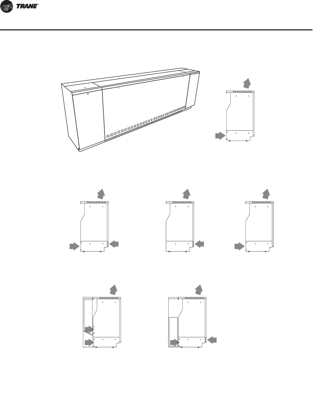
Figure 18. Discharge and inlet arrangements
Available in:
16 5/8" Depth
21 1/4" Depth
Digit 13 = 1
RA Front with FA Back
Available in:
21 1/4" Depth
ONLY
Digit 13 = 5, 6
(5) RH Energy Recovery System
ERS Compatible
(6) LH Energy Recovery System
ERS Compatible
Available in:
16 5/8" Depth
21 1/4" Depth
Digit 13 = 2
100% Return Air Front
Available in:
16 5/8" Depth
21 1/4" Depth
Digit 13 = 3
100% Fresh Air Back
Available in:
16 5/8" Depth
21 1/4" Depth
Digit 23 = 0, A, B, C
0 = Opening Only
A = Grille Discharge
B = Double Deflection Discharge Grille
C = Discharge Grille with Wire Mesh
Available in:
21 1/4" Depth
ONLY
Digit 13 = 4
Dynamic Air Barrier
Inlet Arrangement
Discharge Arrangement
Discharge and Inlet Arrangements
UV-PRC003-EN.book Page 26 Tuesday, June 4, 2013 8:59 PM
UV-PRC003-EN 27
General Data
Figure 19. Falseback and subbase
Coil Combinations
UV-PRC003-EN.book Page 27 Tuesday, June 4, 2013 8:59 PM
28 UV-PRC003-EN
Performance Data
Example 1:
Example 2:
Notes:
•Supply and return coil connections are on the same side.
•In 4-pipe systems, the cooling coil connections are on the opposite end from the heating coil
connections.
•DX coils are always left-hand connections.
•Electric heat coils are always right-hand connections.
•Heating coils (hot water or steam) are right-hand when in the reheat position with DX cooling
coils.
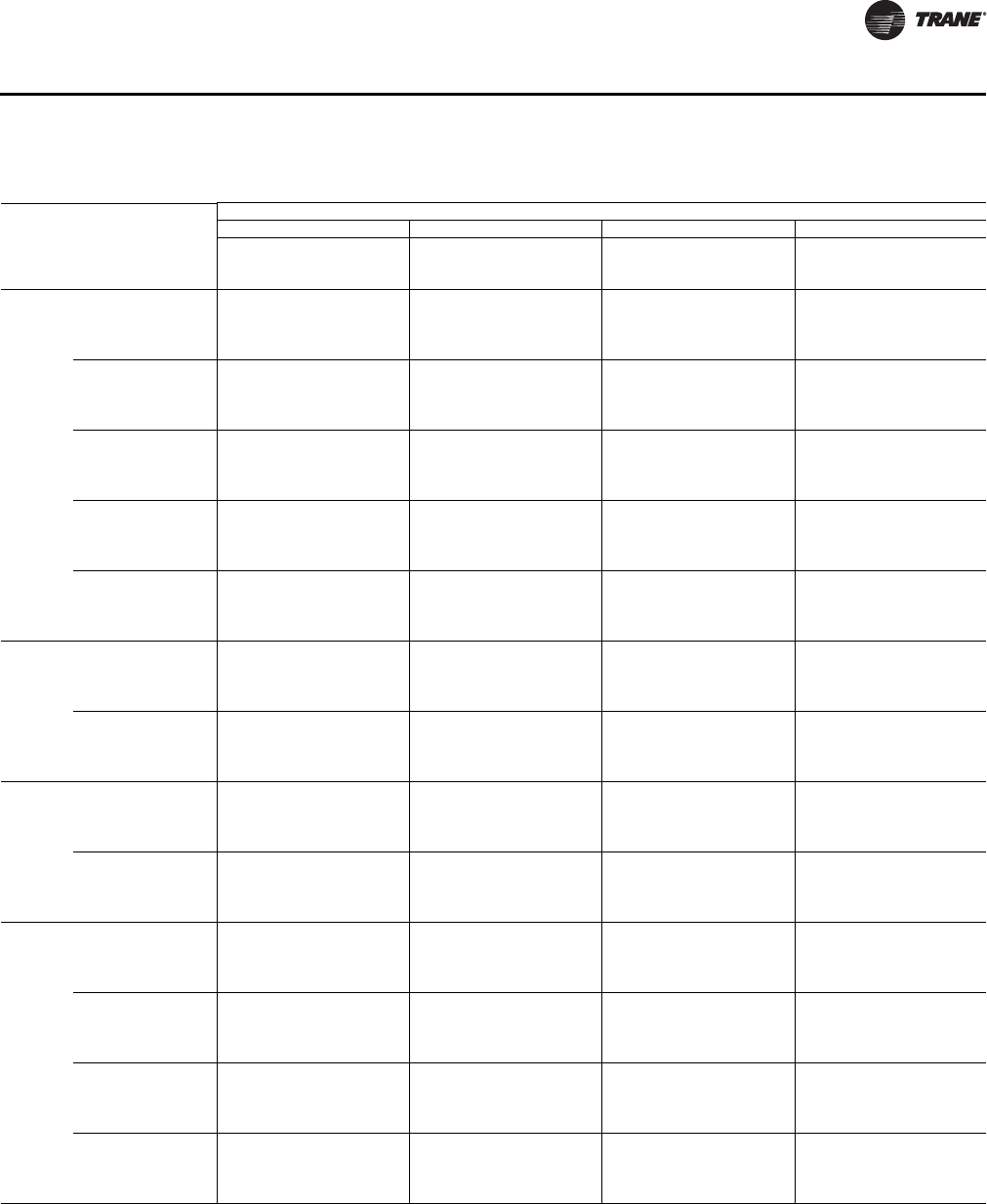
Table 4. Coil combination selection chart (cooling, 2-pipe changeover or heating-only coils)
Coil type Coil description
Preheat or reheat coils
ABCKLMNP
A1-row, 12 fpi Heating only
B2-row, 12 fpi B and C cooling data
available in TOPSS
xxxxxxxx
C2-row, 16 fpi xxxxxxxx
D3-row, 12 fpi x x x xxx
E3-row, 16 fpi x x x xxx
F4-row, 12 fpi x
G4-row, 16 fpi x
H3-row, 16 fpi (EarthWise) x x x
J3-row, DX (R-410A) xxxxxxxx
KSteam, low capacity Heating only
LSteam, high capacity
MElectric heat – 3-element Heating onlyNElectric heat – 4-element
PElectric heat – 6-element
Notes:
1. All coil types on the left side of the grid are available in single-coil, heating only, or 2-pipe changeover with exception of coil type A.
2. For 2-coil or 4-pipe systems, select the cooling coil on the left side of the grid. An X corresponds to a valid heating coil combination.
3. Shaded areas signify valid selections with face and bypass dampers.
4-pipe, chilled water / hot water
Type E, 3-row (16 fpi) cooling coil, may be selected with
Type B, 2-Row (12 fpi) preheat or reheat coil
4-pipe, DX cooling / steam heating
Type J, 3-row DX cooling coil, may be selected with
Type L, high-capacity steam heating coil
UV-PRC003-EN.book Page 28 Tuesday, June 4, 2013 8:59 PM
UV-PRC003-EN 29
Performance Data
Table 5. Airflow through coil combination
Coil combination
Unit size
0750 1000 1250 1500
A833 1072 1406 1669
B788 1032 1293 1578
C759 1011 1315 1515
D748 989 1253 1495
E717 934 1243 1437
F684 1005 1233 1437
G627 983 1215 1524
H717 934 1243 1437
J748 989 1253 1495
K825 1052 1377 1623
L816 1042 1350 1600
B & A 738 1057 1178 1638
B & B 684 1016 1301 1564
B & C 650 994 1320 1504
B & D 639 971 1263 1484
B & E 808 911 1253 1421
B & H 808 911 1253 1421
B & J 669 971 1263 1484
C & A 706 1037 1196 1583
C & C 818 971 1339 1442
C & D 808 947 1282 1421
C & E 779 885 1272 1356
C & H 779 885 1272 1356
C & J 808 947 1282 1421
D & A 695 1016 1143 1564
E & A 662 959 1134 1504
F & A 627 947 1126 1504
G & A 779 923 1320 1421
H & A 662 959 1134 1504
J & A 707 1016 1357 1564
B & K 728 1037 1157 1602
C & K 695 1016 1174 1544
D & K 684 994 1122 1524
E & K 650 935 1114 1463
H & K 650 935 1114 1463
J & K 699 994 1335 1524
B & L 717 1027 1136 1583
C & L 684 1005 1153 1524
D & L 673 983 1102 1504
E & L 639 923 1094 1442
H & L 639 923 1094 1442
J & L 692 983 1102 1504
B & M 767 1093 1182 1362
C & M 744 1075 1195 1324
D & M 736 1057 1156 1311
E & M 714 1005 1149 1266
H & M 714 1005 1149 1266
J & M 736 1057 1156 1475
B & N 759 1084 1169 1350
C & N 736 1066 1182 1311
D & N 729 1047 1142 1296
E & N 707 994 1135 1251
H & N 707 994 1135 1251
J & N 729 1047 1142 1456
B & P 751 1075 1156 1338
C & P 729 1057 1169 1296
D & P 721 1037 1128 1282
E & P 699 983 1121 1544
H & P 699 983 1121 1544
J & P 721 1037 1128 1437
Airflow by Coil Combination
UV-PRC003-EN.book Page 29 Tuesday, June 4, 2013 8:59 PM
30 UV-PRC003-EN
Performance Data
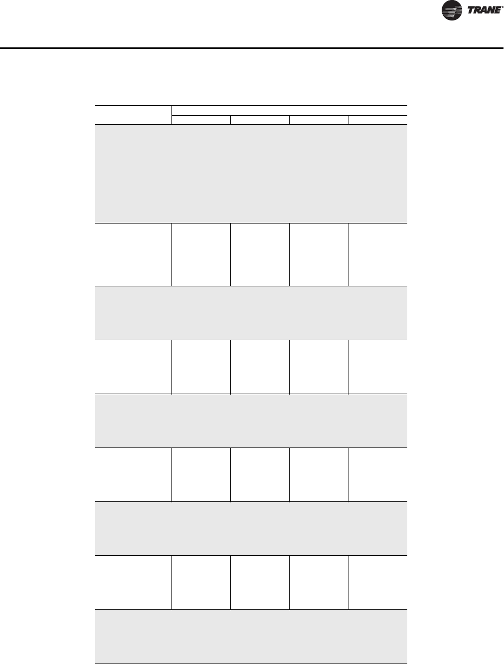
Table 6. Hydronic coil performance summary
Size Coil Rows CFM
Cooling Performance
80/67°F EAT, 45–55°F
Heating Performance
60°F EAT, 160°F EWT
GPM QT QS DP GPM QT DP
0750 A 1 833 Not available 4.0 36.9 5.4
B 2 788 3.2 15.4 12.7 1.6 3.0 51.6 1.4
C 2 759 3.6 17.3 13.7 1.9 3.3 55.6 1.6
D 3 748 4.8 23.4 16.2 3.4 3.5 57.4 1.9
E 3 717 5.2 25.2 16.7 3.9 3.4 57.2 1.8
F 4 684 4.7 22.8 15.1 2.2 3.5 53.5 1.4
G 4 627 4.8 23.2 15.0 2.3 3.8 53.5 1.6
H 3 717 5.7 27.9 17.3 10.3 3.4 61.5 4.1
1000 A 1 1071 Not available 4.0 45.6 6.4
B 2 1035 5.1 24.7 20.1 3.7 4.2 70.8 2.5
C 2 1013 5.8 28.0 21.7 4.8 4.5 76.0 2.9
D 3 990 5.9 28.7 20.7 2.9 4.7 74.6 1.9
E 3 933 6.3 30.7 20.7 3.3 4.6 73.9 1.8
F 4 1007 7.8 38.2 25.8 6.7 4.7 76.2 2.5
G 4 984 8.3 40.7 26.7 7.5 5.1 79.4 2.9
H 3 933 7.4 36.0 24.2 8.8 4.7 79.7 4.0
1250 A 1 1406 Not available 6.0 63.2 15.5
B 2 1293 6.5 31.5 24.6 6.0 5.5 81.0 4.4
C 2 1315 7.3 35.4 26.5 7.4 5.8 90.3 4.9
D 3 1253 8.0 38.9 27.3 6.2 6.0 95.1 3.8
E 3 1243 8.4 41.1 27.5 6.7 5.8 94.8 3.6
F 4 1233 7.7 37.4 27.0 4.0 5.8 92.0 2.3
G 4 1215 8.3 40.3 28.1 4.6 6.4 95.6 2.8
H 3 1243 9.0 43.8 29.2 15.0 5.8 101.8 7.0
1500 A 1 1669 Not available 6.0 77.7 17.4
B 2 1578 8.3 40.5 27.6 11.2 6.4 103.9 6.9
C 2 1515 9.1 44.2 29.0 13.3 7.1 110.3 8.4
D 3 1495 10.4 50.8 34.4 9.1 7.1 117.4 4.6
E 3 1437 10.9 53.4 35.0 10.0 7.0 117.2 4.5
F 4 1437 11.9 58.3 36.6 8.8 7.2 118.5 3.6
G 4 1524 12.6 61.6 38.1 9.8 7.7 126.9 4.1
H 3 1437 12.2 59.7 35.8 14.5 7.2 125.1 5.7
EAT = entering air temperature (°F)
EWT = entering water temperature (°F)
CFM = tate of airflow (ft3/min)
GPM = water flow (gal/min)
QT = total capacity (MBh)
QS = sensible cooling capacity (MBh)
DP = waterside pressure drop (ft H2O)
Hydronic Coil Performance
UV-PRC003-EN.book Page 30 Tuesday, June 4, 2013 8:59 PM
UV-PRC003-EN 31
Performance Data
Table 7. VUV 075, cooling coil cell D, 3-row / 12 fpi
Entering
Wet Bulb
Temp
(°F)
Entering
Dry Bulb
Temp
(°F)
Entering
Water
Temp
(°F)
Flow Rate (gpm)
24610
Total
Capacity
(MBh)
Sensible
Capacity
(MBh)
ΔT
(°F)
Total
Capacity
(MBh)
Sensible
Capacity
(MBh)
ΔT
(°F)
Total
Capacity
(MBh)
Sensible
Capacity
(MBh)
ΔT
(°F)
Total
Capacity
(MBh)
Sensible
Capacity
(MBh)
ΔT
(°F)
61 70 40 11.6 9.5 12.3 17.3 12.0 9.0 21.3 13.5 7.3 25.7 15.2 5.3
42 11.0 9.2 11.7 16.4 11.7 8.5 20.1 13.0 6.9 24.0 14.5 4.9
45 10.1 8.7 10.8 14.9 11.1 7.8 18.2 12.3 6.3 21.5 13.6 4.4
48 9.2 8.2 9.8 13.4 10.4 7.0 16.2 11.6 5.6 18.9 12.7 3.9
75 40 12.7 12.3 13.4 18.9 15.6 9.8 23.3 17.5 8.0 28.0 19.7 5.7
42 12.0 11.9 12.7 17.8 15.1 9.3 21.9 16.9 7.5 26.2 18.8 5.4
45 11.0 11.0 11.7 16.2 14.3 8.5 19.8 15.9 6.8 23.4 17.6 4.8
48 10.0 10.0 10.7 14.6 13.5 7.7 17.7 15.0 6.1 20.6 16.4 4.3
80 40 14.1 14.1 14.8 21.0 18.9 10.8 25.8 21.2 8.8 31.1 23.8 6.4
42 13.3 13.3 14.0 19.8 18.3 10.2 24.3 20.4 8.3 29.1 22.8 5.9
45 12.2 12.2 12.9 18.0 17.3 9.3 22.0 19.3 7.5 26.0 21.3 5.3
48 11.1 11.1 11.8 16.2 16.2 8.5 19.6 18.2 6.8 22.8 19.8 4.7
85 40 15.7 15.7 16.4 23.4 22.0 12.0 28.8 24.7 9.8 34.7 27.7 7.1
42 14.9 14.9 15.6 22.1 21.3 11.4 27.1 23.8 9.3 32.4 26.5 6.6
45 13.6 13.6 14.3 20.1 20.1 10.4 24.5 22.5 8.4 29.0 24.8 5.9
48 12.4 12.4 13.1 18.1 18.1 9.4 21.9 21.1 7.5 25.5 23.1 5.2
90 40 17.5 17.5 18.2 26.1 24.9 13.4 32.1 28.0 10.9 38.7 31.4 7.9
42 16.6 16.6 17.3 24.6 24.1 12.7 30.2 26.9 10.3 36.1 30.1 7.4
45 15.2 15.2 15.9 22.4 22.4 11.5 27.3 25.4 9.3 32.3 28.1 6.6
48 13.8 13.8 14.5 20.2 20.2 10.4 24.4 23.9 8.4 28.4 26.2 5.8
67 75 40 15.9 10.2 16.6 23.7 13.0 12.2 29.1 14.5 9.9 35.1 16.3 7.1
42 15.0 9.9 15.7 22.3 12.5 11.5 27.4 14.0 9.4 32.8 15.6 6.7
45 13.8 9.4 14.5 20.3 11.9 10.5 24.8 13.2 8.5 29.3 14.6 6.0
48 12.5 8.8 13.2 18.3 11.2 9.5 22.1 12.5 7.6 25.8 13.6 5.3
80 40 16.7 13.2 17.4 24.8 16.8 12.8 30.6 18.8 10.4 36.8 21.2 7.5
42 15.8 12.8 16.5 23.4 16.2 12.1 28.7 18.2 9.8 34.4 20.3 7.0
45 14.4 12.1 15.1 21.3 15.4 11.0 26.0 17.1 8.9 30.7 18.9 6.3
48 13.1 11.4 13.8 19.2 14.5 9.9 23.2 16.1 8.0 27.0 17.6 5.5
85 40 17.7 16.1 18.4 26.4 20.5 13.6 32.5 23.0 11.1 39.2 25.8 8.0
42 16.8 15.6 17.5 24.9 19.8 12.8 30.6 22.2 10.4 36.6 24.7 7.5
45 15.4 14.8 16.1 22.7 18.8 11.7 27.7 20.9 9.4 32.7 23.1 6.7
48 14.0 13.9 14.7 20.4 17.8 10.6 24.7 19.7 8.5 28.8 21.5 5.9
90 40 19.0 18.9 19.7 28.3 24.1 14.5 34.9 27.0 11.9 42.0 30.4 8.5
42 18.0 18.0 18.7 26.8 23.3 13.7 32.8 26.0 11.2 39.3 29.1 8.0
45 16.5 16.5 17.2 24.3 22.1 12.5 29.7 24.6 10.1 35.1 27.1 7.2
48 15.0 15.0 15.7 21.9 20.9 11.3 26.5 23.1 9.1 30.9 25.3 6.3
70 75 40 18.1 8.9 18.8 26.9 11.3 13.8 33.1 12.7 11.3 39.9 14.3 8.1
42 17.1 8.6 17.8 25.4 11.0 13.0 31.2 12.3 10.6 37.3 13.7 7.6
45 15.7 8.2 16.4 23.1 10.4 11.9 28.2 11.6 9.6 33.3 12.8 6.8
48 14.2 7.7 14.9 20.8 9.8 10.8 25.2 10.9 8.6 29.3 11.9 6.0
80 40 18.6 12.0 19.3 27.7 15.2 14.2 34.0 17.1 11.6 41.0 19.2 8.3
42 17.6 11.6 18.3 26.1 14.7 13.4 32.0 16.5 10.9 38.3 18.4 7.8
45 16.1 11.0 16.8 23.8 14.0 12.2 29.0 15.6 9.9 34.2 17.2 7.0
48 14.6 10.4 15.3 21.4 13.2 11.0 25.9 14.6 8.8 30.1 16.0 6.2
85 40 19.4 15.0 20.1 28.9 19.1 14.8 35.5 21.4 12.1 42.8 24.1 8.7
42 18.4 14.5 19.0 27.2 18.5 14.0 33.4 20.7 11.4 40.0 23.0 8.1
45 16.8 13.8 17.5 24.8 17.5 12.7 30.2 19.5 10.3 35.7 21.5 7.3
48 15.3 13.0 15.9 22.3 16.5 11.5 27.0 18.3 9.2 31.4 20.0 6.4
90 40 20.4 18.0 21.1 30.4 22.9 15.6 37.5 25.7 12.7 45.1 28.8 9.2
42 19.3 17.4 20.0 28.7 22.1 14.7 35.2 24.7 12.0 42.2 27.6 8.6
45 17.7 16.5 18.4 26.1 21.0 13.4 31.9 23.4 10.8 37.7 25.8 7.7
48 16.1 15.5 16.8 23.5 19.8 12.1 28.4 22.0 9.7 33.1 24.0 6.8
Cooling - 075 - Coil D
UV-PRC003-EN.book Page 31 Tuesday, June 4, 2013 8:59 PM

32 UV-PRC003-EN
Performance Data
Table 8. VUV 075, cooling coil E, 3-row / 16 fpi
Entering
Wet Bulb
Temp
(°F)
Entering
Dry Bulb
Temp
(°F)
Entering
Water
Temp
(°F)
Flow Rate (gpm)
24610
Total
Capacity
(MBh)
Sensible
Capacity
(MBh)
ΔT
(°F)
Total
Capacity
(MBh)
Sensible
Capacity
(MBh)
ΔT
(°F)
Total
Capacity
(MBh)
Sensible
Capacity
(MBh)
ΔT
(°F)
Total
Capacity
(MBh)
Sensible
Capacity
(MBh)
ΔT
(°F)
61 70 40 12.0 9.5 12.6 17.9 12.1 9.3 22.0 13.6 7.6 26.4 15.3 5.4
42 11.3 9.2 12.0 16.9 11.7 8.8 20.8 13.1 7.1 24.8 14.7 5.1
45 10.4 8.8 11.1 15.4 11.1 8.0 18.8 12.4 6.5 22.2 13.7 4.6
48 9.4 8.3 10.1 13.9 10.5 7.3 16.8 11.6 5.8 19.5 12.7 4.0
75 40 13.0 12.4 13.7 19.5 15.7 10.1 24.0 17.7 8.2 28.8 19.9 5.9
42 12.3 12.0 13.0 18.4 15.2 9.6 22.6 17.0 7.8 27.0 19.0 5.5
45 11.3 11.3 12.0 16.8 14.4 8.7 20.5 16.0 7.1 24.2 17.7 5.0
48 10.3 10.3 11.0 15.1 13.6 7.9 18.3 15.1 6.3 21.3 16.5 4.4
80 40 14.5 14.5 15.1 21.6 19.0 11.2 26.7 21.4 9.1 32.0 24.1 6.5
42 13.7 13.7 14.4 20.4 18.4 10.6 25.1 20.6 8.6 29.9 23.0 6.1
45 12.5 12.5 13.2 18.6 17.5 9.7 22.7 19.4 7.8 26.8 21.5 5.5
48 11.4 11.4 12.1 16.8 16.5 8.7 20.3 18.3 7.0 23.6 19.9 4.9
85 40 16.1 16.1 16.8 24.2 22.1 12.4 29.8 24.9 10.1 35.7 28.0 7.3
42 15.3 15.3 16.0 22.8 21.4 11.8 28.0 24.0 9.6 33.4 26.8 6.8
45 14.0 14.0 14.7 20.8 20.3 10.7 25.4 22.6 8.7 29.9 25.0 6.1
48 12.7 12.7 13.4 18.7 18.7 9.7 22.7 21.2 7.8 26.3 23.2 5.4
90 40 18.0 18.0 18.7 26.9 25.1 13.8 33.2 28.2 11.3 39.8 31.7 8.1
42 17.0 17.0 17.7 25.4 24.3 13.1 31.2 27.1 10.6 37.2 30.3 7.6
45 15.6 15.6 16.3 23.2 23.0 11.9 28.3 25.6 9.7 33.3 28.3 6.8
48 14.2 14.2 14.9 20.9 20.9 10.8 25.3 24.1 8.7 29.4 26.3 6.0
67 75 40 16.3 10.3 17.0 24.4 13.1 12.5 30.1 14.7 10.3 36.1 16.5 7.4
42 15.4 9.9 16.1 23.1 12.6 11.9 28.3 14.1 9.7 33.8 15.8 6.9
45 14.2 9.4 14.8 21.0 12.0 10.8 25.6 13.3 8.8 30.2 14.7 6.2
48 12.9 8.9 13.5 18.9 11.3 9.8 22.9 12.5 7.9 26.6 13.7 5.5
80 40 17.1 13.3 17.8 25.6 16.9 13.2 31.6 19.0 10.7 37.9 21.4 7.7
42 16.2 12.9 16.9 24.2 16.3 12.4 29.7 18.3 10.1 35.4 20.4 7.2
45 14.8 12.2 15.5 22.0 15.5 11.4 26.9 17.2 9.2 31.7 19.1 6.5
48 13.5 11.5 14.2 19.9 14.6 10.3 24.1 16.2 8.2 27.9 17.7 5.7
85 40 18.2 16.2 18.9 27.3 20.6 14.0 33.6 23.2 11.4 40.3 26.1 8.2
42 17.3 15.7 17.9 25.8 19.9 13.2 31.6 22.3 10.8 37.7 24.9 7.7
45 15.8 14.9 16.5 23.5 18.9 12.1 28.6 21.1 9.8 33.8 23.3 6.9
48 14.4 14.1 15.0 21.2 17.9 10.9 25.6 19.8 8.8 29.7 21.6 6.1
90 40 19.5 19.1 20.2 29.3 24.2 15.0 36.0 27.2 12.2 43.2 30.6 8.8
42 18.5 18.5 19.2 27.6 23.4 14.2 33.9 26.2 11.5 40.5 29.3 8.2
45 17.0 17.0 17.6 25.2 22.2 12.9 30.7 24.7 10.5 36.2 27.3 7.4
48 15.4 15.4 16.1 22.7 21.0 11.727.5 23.3 9.4 31.9 25.4 6.5
70 75 40 18.6 9.0 19.2 27.8 11.4 14.2 34.2 12.8 11.6 41.1 14.4 8.4
42 17.6 8.7 18.3 26.3 11.0 13.5 32.2 12.4 11.0 38.4 13.8 7.8
45 16.1 8.3 16.8 23.9 10.5 12.3 29.2 11.7 10.0 34.4 12.9 7.0
48 14.6 7.8 15.3 21.6 9.9 11.1 26.1 11.0 8.9 30.3 12.0 6.2
80 40 19.1 12.1 19.8 28.5 15.3 14.6 35.2 17.2 11.9 42.2 19.4 8.6
42 18.1 11.7 18.7 27.0 14.8 13.8 33.1 16.6 11.3 39.5 18.6 8.0
45 16.5 11.1 17.2 24.6 14.1 12.6 30.0 15.7 10.2 35.3 17.3 7.2
48 15.0 10.5 15.7 22.2 13.3 11.4 26.8 14.7 9.2 31.1 16.1 6.4
85 40 19.9 15.1 20.6 29.8 19.2 15.2 36.7 21.6 12.5 44.0 24.3 8.9
42 18.8 14.7 19.5 28.1 18.6 14.4 34.5 20.8 11.7 41.2 23.2 8.4
45 17.3 13.9 17.9 25.6 17.6 13.2 31.3 19.6 10.7 36.9 21.7 7.5
48 15.7 13.1 16.4 23.1 16.7 11.9 28.0 18.4 9.6 32.5 20.1 6.6
90 40 21.0 18.1 21.7 31.4 23.0 16.0 38.7 25.9 13.1 46.4 29.1 9.4
42 19.9 17.5 20.6 29.7 22.3 15.2 36.4 24.9 12.4 43.4 27.8 8.8
45 18.2 16.7 18.9 27.0 21.1 13.9 33.0 23.5 11.2 38.9 26.0 7.9
48 16.5 15.7 17.2 24.4 20.0 12.5 29.5 22.1 10.1 34.2 24.1 7.0
Cooling - 075 - Coil E
UV-PRC003-EN.book Page 32 Tuesday, June 4, 2013 8:59 PM

UV-PRC003-EN 33
Performance Data
Table 9. VUV 075, cooling coil F, 4-row / 12 fpi
Entering
Wet Bulb
Temp
(°F)
Entering
Dry Bulb
Temp
(°F)
Entering
Water
Temp
(°F)
Flow Rate (gpm)
24610
Total
Capacity
(MBh)
Sensible
Capacity
(MBh)
ΔT
(°F)
Total
Capacity
(MBh)
Sensible
Capacity
(MBh)
ΔT
(°F)
Total
Capacity
(MBh)
Sensible
Capacity
(MBh)
ΔT
(°F)
Total
Capacity
(MBh)
Sensible
Capacity
(MBh)
ΔT
(°F)
61 70 40 11.9 9.1 12.6 17.1 11.4 8.9 20.9 12.7 7.2 25.1 14.3 5.2
42 11.2 8.8 11.9 16.1 11.0 8.4 19.6 12.3 6.8 23.5 13.7 4.8
45 10.2 8.4 10.9 14.7 10.4 7.7 17.8 11.5 6.2 21.1 12.8 4.4
48 9.2 7.9 9.9 13.2 9.8 6.9 15.9 10.8 5.5 18.6 11.8 3.9
75 40 13.0 11.8 13.6 18.7 14.7 9.7 22.8 16.5 7.8 27.4 18.6 5.6
42 12.3 11.4 12.9 17.6 14.2 9.1 21.4 15.9 7.4 25.7 17.8 5.3
45 11.2 10.8 11.9 16.0 13.5 8.3 19.4 14.9 6.7 23.0 16.5 4.7
48 10.1 10.1 10.8 14.4 12.7 7.5 17.3 14.0 6.0 20.3 15.3 4.2
80 40 14.4 14.3 15.1 20.7 17.8 10.7 25.2 20.0 8.6 30.4 22.5 6.2
42 13.6 13.6 14.3 19.5 17.2 10.1 23.8 19.2 8.1 28.5 21.5 5.8
45 12.4 12.4 13.1 17.7 16.3 9.2 21.5 18.1 7.4 25.5 20.0 5.2
48 11.2 11.2 11.9 15.9 15.3 8.3 19.2 17.0 6.6 22.5 18.6 4.6
85 40 16.0 16.0 16.7 23.1 20.7 11.9 28.2 23.2 9.6 33.9 26.2 6.9
42 15.2 15.2 15.8 21.8 20.0 11.2 26.5 22.4 9.1 31.8 25.0 6.5
45 13.8 13.8 14.5 19.8 18.9 10.2 24.0 21.0 8.2 28.5 23.3 5.8
48 12.5 12.5 13.1 17.8 17.8 9.2 21.4 19.7 7.4 25.1 21.6 5.2
90 40 17.9 17.9 18.6 25.7 23.5 13.2 31.4 26.3 10.7 37.8 29.7 7.7
42 16.9 16.9 17.6 24.3 22.7 12.5 29.6 25.3 10.1 35.4 28.3 7.2
45 15.4 15.4 16.1 22.1 21.5 11.4 26.7 23.8 9.1 31.8 26.4 6.5
48 13.9 13.9 14.6 19.8 19.8 10.2 23.9 22.3 8.2 28.0 24.5 5.7
67 75 40 16.2 9.8 16.9 23.3 12.2 12.0 28.5 13.7 9.7 34.3 15.4 7.0
42 15.3 9.5 16.0 22.0 11.8 11.4 26.8 13.2 9.2 32.1 14.8 6.6
45 14.0 9.0 14.7 20.0 11.2 10.3 24.2 12.4 8.3 28.8 13.7 5.9
48 12.6 8.5 13.3 18.0 10.5 9.3 21.6 11.6 7.4 25.4 12.7 5.2
80 40 17.0 12.7 17.7 24.5 15.8 12.6 29.9 17.7 10.2 35.9 20.0 7.3
42 16.1 12.3 16.8 23.1 15.3 11.928.1 17.1 9.6 33.7 19.1 6.9
45 14.7 11.7 15.3 21.0 14.5 10.8 25.4 16.1 8.7 30.2 17.8 6.2
48 13.2 11.0 13.9 18.8 13.6 9.8 22.7 15.1 7.8 26.7 16.5 5.5
85 40 18.1 15.5 18.8 26.1 19.3 13.4 31.8 21.7 10.8 38.3 24.4 7.8
42 17.1 15.0 17.8 24.6 18.7 12.6 29.9 20.8 10.2 35.9 23.3 7.3
45 15.6 14.2 16.3 22.4 17.7 11.5 27.1 19.6 9.3 32.2 21.7 6.6
48 14.1 13.4 14.8 20.1 16.6 10.4 24.2 18.4 8.3 28.4 20.1 5.8
90 40 19.4 18.2 20.1 28.0 22.7 14.3 34.1 25.4 11.6 41.0 28.7 8.3
42 18.4 17.6 19.1 26.4 21.9 13.5 32.1 24.5 10.9 38.5 27.4 7.8
45 16.7 16.7 17.4 24.0 20.7 12.3 29.1 23.0 9.9 34.5 25.5 7.0
48 15.1 15.1 15.8 21.5 19.5 11.1 25.9 21.6 8.9 30.4 23.7 6.2
70 75 40 18.5 8.6 19.1 26.6 10.7 13.6 32.4 12.0 11.0 39.0 13.5 7.9
42 17.4 8.3 18.1 25.1 10.3 12.9 30.5 11.5 10.4 36.5 12.9 7.4
45 15.9 7.9 16.6 22.8 9.8 11.7 27.6 10.9 9.4 32.8 12.0 6.7
48 14.3 7.4 15.0 20.4 9.2 10.6 24.6 10.2 8.4 28.9 11.2 5.9
80 40 19.0 11.5 19.6 27.3 14.4 14.0 33.3 16.1 11.3 40.0 18.2 8.1
42 17.9 11.2 18.6 25.7 13.9 13.2 31.3 15.5 10.7 37.5 17.3 7.6
45 16.3 10.6 17.0 23.4 13.1 12.0 28.3 14.6 9.7 33.7 16.2 6.9
48 14.7 10.0 15.4 21.0 12.4 10.8 25.3 13.7 8.7 29.7 15.0 6.1
85 40 19.8 14.4 20.5 28.5 18.0 14.6 34.7 20.2 11.8 41.8 22.7 8.5
42 18.7 14.0 19.4 26.9 17.4 13.8 32.7 19.4 11.1 39.2 21.7 8.0
45 17.0 13.3 17.7 24.4 16.5 12.6 29.6 18.3 10.1 35.1 20.2 7.2
48 15.4 12.5 16.1 21.9 15.5 11.3 26.4 17.1 9.0 31.0 18.8 6.3
90 40 20.9 17.3 21.5 30.0 21.6 15.4 36.6 24.2 12.4 44.1 27.2 8.9
42 19.7 16.7 20.4 28.3 20.8 14.5 34.5 23.3 11.7 41.3 26.0 8.4
45 18.0 15.9 18.7 25.7 19.7 13.2 31.2 21.9 10.6 37.0 24.2 7.5
48 16.2 14.9 16.9 23.1 18.6 11.9 27.8 20.5 9.5 32.7 22.5 6.7
Cooling - 075 - Coil F
UV-PRC003-EN.book Page 33 Tuesday, June 4, 2013 8:59 PM
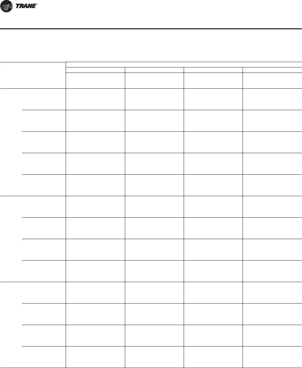
34 UV-PRC003-EN
Performance Data
Table 10. VUV 075, coil G, 4-row / 16 fpi
Entering
Wet Bulb
Temp
(°F)
Entering
Dry Bulb
Temp
(°F)
Entering
Water
Temp
(°F)
Flow Rate (gpm)
24610
Total
Capacity
(MBh)
Sensible
Capacity
(MBh)
ΔT
(°F)
Total
Capacity
(MBh)
Sensible
Capacity
(MBh)
ΔT
(°F)
Total
Capacity
(MBh)
Sensible
Capacity
(MBh)
ΔT
(°F)
Total
Capacity
(MBh)
Sensible
Capacity
(MBh)
ΔT
(°F)
61 70 40 12.0 9.0 12.7 17.3 11.2 9.0 21.0 12.6 7.2 25.1 14.1 5.2
42 11.4 8.7 12.0 16.3 10.8 8.5 19.8 12.1 6.8 23.5 13.5 4.8
45 10.4 8.2 11.0 14.8 10.2 7.8 17.9 11.3 6.2 21.1 12.6 4.4
48 9.3 7.7 10.0 13.3 9.6 7.0 16.0 10.6 5.6 18.6 11.6 3.9
75 40 13.1 11.6 13.8 18.9 14.5 9.8 22.9 16.3 7.9 27.3 18.3 5.6
42 12.4 11.2 13.1 17.8 14.0 9.2 21.6 15.7 7.4 25.6 17.5 5.3
45 11.3 10.7 12.0 16.2 13.2 8.4 19.6 14.7 6.7 23.0 16.3 4.7
48 10.2 10.0 10.9 14.5 12.4 7.6 17.5 13.8 6.0 20.3 15.0 4.2
80 40 14.6 14.1 15.2 20.9 17.6 10.8 25.4 19.7 8.7 30.3 22.2 6.2
42 13.7 13.6 14.4 19.8 17.0 10.2 24.0 19.0 8.2 28.4 21.2 5.8
45 12.5 12.5 13.2 18.0 16.0 9.3 21.7 17.8 7.5 25.5 19.7 5.2
48 11.3 11.3 12.0 16.1 15.1 8.4 19.4 16.7 6.7 22.5 18.2 4.6
85 40 16.2 16.2 16.9 23.4 20.5 12.0 28.4 22.9 9.7 33.8 25.8 6.9
42 15.3 15.3 16.0 22.0 19.7 11.4 26.7 22.0 9.1 31.7 24.6 6.5
45 14.0 14.0 14.7 20.0 18.6 10.4 24.2 20.7 8.3 28.5 22.9 5.8
48 12.6 12.6 13.3 18.0 17.5 9.3 21.6 19.4 7.4 25.2 21.2 5.2
90 40 18.1 18.1 18.8 26.0 23.2 13.4 31.6 26.0 10.8 37.7 29.2 7.7
42 17.1 17.1 17.8 24.6 22.4 12.6 29.8 25.0 10.2 35.4 27.9 7.2
45 15.6 15.6 16.3 22.3 21.1 11.5 27.0 23.5 9.2 31.8 26.0 6.5
48 14.0 14.0 14.7 20.1 19.9 10.4 24.1 21.9 8.3 28.0 24.0 5.7
67 75 40 16.4 9.6 17.1 23.6 12.1 12.1 28.7 13.5 9.8 34.2 15.2 7.0
42 15.5 9.3 16.2 22.3 11.6 11.5 27.0 13.0 9.2 32.1 14.5 6.6
45 14.1 8.9 14.8 20.3 11.0 10.5 24.5 12.2 8.4 28.8 13.5 5.9
48 12.7 8.3 13.4 18.2 10.3 9.4 21.8 11.4 7.5 25.4 12.5 5.2
80 40 17.2 12.5 17.9 24.8 15.6 12.7 30.1 17.5 10.3 35.9 19.7 7.3
42 16.3 12.1 17.0 23.4 15.1 12.028.4 16.8 9.7 33.7 18.8 6.9
45 14.8 11.5 15.5 21.3 14.2 11.0 25.7 15.8 8.8 30.2 17.5 6.2
48 13.3 10.8 14.0 19.1 13.4 9.9 22.9 14.8 7.9 26.7 16.2 5.5
85 40 18.3 15.2 19.0 26.4 19.1 13.5 32.1 21.4 10.9 38.2 24.1 7.8
42 17.3 14.8 18.0 24.9 18.4 12.8 30.2 20.5 10.3 35.8 23.0 7.3
45 15.8 14.0 16.5 22.6 17.4 11.7 27.3 19.3 9.3 32.2 21.3 6.6
48 14.2 13.2 14.9 20.3 16.3 10.5 24.4 18.0 8.4 28.4 19.7 5.8
90 40 19.7 17.9 20.4 28.3 22.4 14.5 34.4 25.1 11.7 41.0 28.3 8.3
42 18.6 17.3 19.3 26.7 21.6 13.7 32.4 24.1 11.0 38.4 27.0 7.8
45 16.9 16.4 17.6 24.3 20.4 12.5 29.3 22.7 10.0 34.5 25.1 7.0
48 15.2 15.2 15.9 21.8 19.2 11.2 26.2 21.2 9.0 30.5 23.2 6.2
70 75 40 18.7 8.4 19.4 26.9 10.6 13.8 32.7 11.8 11.1 38.9 13.3 7.9
42 17.6 8.2 18.3 25.4 10.2 13.0 30.8 11.4 10.5 36.5 12.7 7.4
45 16.1 7.7 16.8 23.1 9.6 11.9 27.9 10.7 9.5 32.8 11.8 6.7
48 14.5 7.3 15.2 20.7 9.0 10.7 24.9 10.0 8.5 28.9 10.9 5.9
80 40 19.2 11.3 19.9 27.6 14.2 14.1 33.5 15.9 11.4 40.0 17.9 8.1
42 18.1 11.0 18.8 26.0 13.7 13.4 31.6 15.3 10.8 37.5 17.1 7.6
45 16.5 10.4 17.2 23.7 12.9 12.2 28.6 14.4 9.8 33.7 15.9 6.9
48 14.9 9.8 15.6 21.3 12.1 11.0 25.5 13.4 8.7 29.7 14.7 6.1
85 40 20.0 14.2 20.7 28.8 17.8 14.7 35.0 19.9 11.9 41.7 22.4 8.5
42 18.9 13.7 19.6 27.2 17.1 13.9 33.0 19.1 11.2 39.1 21.4 8.0
45 17.2 13.0 17.9 24.7 16.2 12.7 29.9 18.0 10.2 35.1 19.9 7.2
48 15.5 12.3 16.2 22.2 15.2 11.4 26.7 16.8 9.1 31.0 18.4 6.3
90 40 21.1 17.0 21.8 30.4 21.3 15.5 36.9 23.9 12.5 44.0 26.8 8.9
42 19.9 16.5 20.6 28.7 20.5 14.7 34.8 22.9 11.8 41.3 25.6 8.4
45 18.2 15.6 18.9 26.1 19.4 13.4 31.5 21.5 10.7 37.0 23.8 7.5
48 16.4 14.7 17.0 23.4 18.2 12.0 28.1 20.1 9.6 32.7 22.0 6.7
Cooling - 075 - Coil G
UV-PRC003-EN.book Page 34 Tuesday, June 4, 2013 8:59 PM

UV-PRC003-EN 35
Performance Data
Table 11. VUV 075, cooling coil H, 3-row / 16 fpi
Entering
Wet Bulb
Temp
(°F)
Entering
Dry Bulb
Temp
(°F)
Entering
Water
Temp
(°F)
Flow Rate (gpm)
24610
Total
Capacity
(MBh)
Sensible
Capacity
(MBh)
ΔT
(°F)
Total
Capacity
(MBh)
Sensible
Capacity
(MBh)
ΔT
(°F)
Total
Capacity
(MBh)
Sensible
Capacity
(MBh)
ΔT
(°F)
Total
Capacity
(MBh)
Sensible
Capacity
(MBh)
ΔT
(°F)
61 70 40 13.8 10.5 14.5 20.1 12.7 10.4 23.2 13.8 8.0 26.1 14.9 5.4
42 13.2 10.3 13.8 19.0 12.3 9.8 21.8 13.3 7.5 24.6 14.2 5.0
45 12.1 9.9 12.8 17.2 11.7 8.9 19.8 12.5 6.8 22.2 13.3 4.6
48 11.0 9.5 11.7 15.4 11.1 8.0 17.6 11.8 6.1 19.7 12.4 4.1
75 40 15.0 13.6 15.7 21.9 16.5 11.3 25.3 17.9 8.7 28.5 19.2 5.8
42 14.3 13.3 15.0 20.7 15.9 10.7 23.8 17.2 8.2 26.8 18.4 5.5
45 13.2 12.8 13.9 18.8 15.1 9.7 21.5 16.2 7.4 24.2 17.2 5.0
48 12.0 12.0 12.7 16.8 14.3 8.7 19.2 15.2 6.6 21.5 16.1 4.4
80 40 16.7 16.4 17.4 24.3 19.9 12.5 28.1 21.7 9.6 31.6 23.3 6.5
42 15.9 15.9 16.6 22.9 19.3 11.8 26.4 20.8 9.0 29.7 22.3 6.1
45 14.7 14.7 15.4 20.8 18.3 10.8 23.9 19.6 8.2 26.8 20.9 5.5
48 13.3 13.3 14.0 18.6 17.4 9.6 21.3 18.5 7.3 23.8 19.5 4.9
85 40 18.6 18.6 19.3 27.1 23.2 13.9 31.3 25.2 10.7 35.3 27.1 7.2
42 17.8 17.8 18.4 25.6 22.4 13.1 29.5 24.2 10.1 33.1 25.9 6.8
45 16.4 16.4 17.1 23.2 21.3 12.0 26.7 22.8 9.1 29.9 24.3 6.1
48 14.9 14.9 15.6 20.8 20.2 10.7 23.7 21.5 8.1 26.6 22.7 5.5
90 40 20.8 20.8 21.4 30.3 26.3 15.5 34.9 28.6 11.9 39.3 30.7 8.0
42 19.8 19.8 20.5 28.5 25.4 14.6 32.9 27.5 11.2 37.0 29.4 7.5
45 18.3 18.3 18.9 25.9 24.1 13.3 29.7 25.8 10.1 33.3 27.5 6.8
48 16.6 16.6 17.3 23.2 22.9 11.9 26.5 24.3 9.1 29.6 25.7 6.1
67 75 40 18.8 11.3 19.5 27.4 13.7 14.1 31.7 14.9 10.8 35.6 16.0 7.3
42 17.9 11.0 18.6 25.9 13.2 13.3 29.8 14.3 10.2 33.5 15.3 6.8
45 16.5 10.7 17.2 23.5 12.6 12.1 27.0 13.5 9.2 30.2 14.3 6.2
48 15.0 10.2 15.7 21.0 11.9 10.8 24.0 12.7 8.2 26.9 13.4 5.5
80 40 19.8 14.6 20.4 28.8 17.7 14.7 33.2 19.2 11.3 37.4 20.7 7.6
42 18.8 14.3 19.5 27.2 17.1 13.931.3 18.5 10.7 35.2 19.8 7.2
45 17.4 13.8 18.0 24.6 16.2 12.7 28.3 17.4 9.7 31.7 18.5 6.5
48 15.8 13.3 16.5 22.0 15.4 11.4 25.2 16.4 8.6 28.2 17.3 5.8
85 40 21.0 17.8 21.7 30.6 21.6 15.7 35.4 23.5 12.0 39.8 25.3 8.1
42 20.0 17.4 20.7 28.9 20.9 14.8 33.3 22.6 11.3 37.4 24.2 7.6
45 18.5 16.8 19.2 26.2 19.8 13.5 30.1 21.3 10.3 33.8 22.6 6.9
48 16.8 16.2 17.5 23.5 18.8 12.1 26.8 20.0 9.2 30.0 21.1 6.1
90 40 22.6 20.9 23.2 32.9 25.4 16.8 38.0 27.6 12.9 42.7 29.7 8.7
42 21.5 20.5 22.2 31.0 24.6 15.9 35.7 26.5 12.1 40.2 28.4 8.2
45 19.8 19.8 20.5 28.2 23.3 14.4 32.3 25.0 11.0 36.2 26.6 7.4
48 18.0 18.0 18.7 25.2 22.1 12.9 28.8 23.5 9.8 32.2 24.8 6.6
70 75 40 21.4 9.9 22.1 31.2 12.0 16.0 36.0 13.0 12.2 40.6 14.0 8.3
42 20.4 9.7 21.1 29.5 11.6 15.1 33.9 12.5 11.5 38.1 13.4 7.8
45 18.8 9.3 19.5 26.7 11.0 13.7 30.7 11.8 10.5 34.4 12.5 7.0
48 17.1 9.0 17.8 23.9 10.4 12.3 27.3 11.1 9.3 30.6 11.7 6.3
80 40 22.0 13.3 22.7 32.1 16.1 16.4 37.0 17.5 12.6 41.7 18.8 8.5
42 21.0 13.0 21.7 30.3 15.6 15.5 34.8 16.8 11.8 39.2 18.0 8.0
45 19.3 12.5 20.0 27.5 14.8 14.1 31.5 15.8 10.7 35.3 16.8 7.2
48 17.6 12.0 18.3 24.6 14.0 12.6 28.1 14.9 9.6 31.4 15.7 6.4
85 40 23.0 16.6 23.7 33.5 20.1 17.1 38.6 21.9 13.1 43.5 23.5 8.8
42 21.9 16.3 22.6 31.6 19.5 16.1 36.4 21.0 12.4 40.9 22.5 8.3
45 20.2 15.7 20.9 28.7 18.5 14.7 32.9 19.8 11.2 36.9 21.1 7.5
48 18.4 15.1 19.0 25.6 17.5 13.2 29.3 18.6 10.0 32.8 19.7 6.7
90 40 24.2 19.9 24.9 35.3 24.1 18.0 40.7 26.2 13.8 45.8 28.2 9.3
42 23.1 19.5 23.8 33.3 23.3 17.0 38.3 25.2 13.0 43.1 27.0 8.8
45 21.3 18.8 22.0 30.2 22.1 15.4 34.7 23.7 11.8 38.9 25.2 7.9
48 19.4 18.1 20.0 27.0 21.0 13.8 30.9 22.3 10.5 34.5 23.6 7.0
Cooling - 075 - Coil H
UV-PRC003-EN.book Page 35 Tuesday, June 4, 2013 8:59 PM
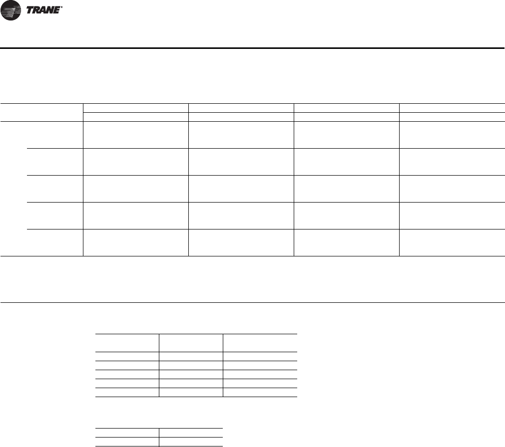
36 UV-PRC003-EN
Performance Data
Table 12. VUV 075, cooling coil J (DX)
Size EWB
Suct
Temp
EDB = 70°F EDB = 75°F EDB = 80°F EDB = 85°F
TC SC LDBLWBTC SC LDBLWBTC SC LDBLWBTC SC LDBLWB
750 61 40 22.8 15.0 51.4 50.0 25.0 19.9 50.4 48.8 27.7 24.3 49.9 47.2 30.9 28.5 49.7 45.4
45 19.1 13.7 53.0 52.0 20.9 18.1 52.6 51.0 23.2 22.1 52.6 49.7 25.9 25.9 52.9 48.2
50 15.4 12.3 54.8 53.8 16.9 16.2 54.9 53.1 18.7 18.7 56.9 52.1 20.9 20.9 59.1 50.9
64 40 27.1 13.0 53.9 51.6 28.6 18.3 52.3 50.8 30.4 23.2 51.3 49.8 32.7 27.9 50.5 48.5
45 22.7 11.8 55.4 53.9 23.9 16.6 54.5 53.2 25.5 21.1 53.9 52.3 27.4 25.3 53.7 51.3
50 18.3 10.6 56.9 56.0 19.3 14.9 56.6 55.5 20.6 19.0 56.5 54.8 22.1 22.1 57.6 54.0
67 40 32.1 10.4 57.1 53.1 33.1 16.0 55.2 52.5 34.3 21.3 53.6 51.8 35.9 26.3 52.4 50.9
45 26.9 9.4 58.4 55.7 27.8 14.5 57.1 55.1 28.8 19.3 56.1 54.6 30.1 23.9 55.4 53.9
50 21.7 8.5 59.5 58.1 22.4 13.1 58.8 57.7 23.2 17.4 58.5 57.2 24.3 21.5 58.4 56.7
70 40 38.4 13.2 58.7 54.1 39.2 18.7 56.9 53.6 40.3 24.0 55.3 53.0
45 32.2 12.0 60.1 57.0 32.9 17.0 59.0 56.6 33.7 21.9 57.9 56.2
50 26.0 10.8 61.6 59.8 26.5 15.3 61.1 59.5 27.2 19.7 60.6 59.2
73 40 44.8 15.6 60.7 55.3 45.6 21.1 58.9 54.8
45 37.6 14.2 62.4 58.6 38.2 19.2 61.2 58.3
50 30.3 12.8 64.2 61.8 30.8 17.3 63.6 61.5
EDB = Entering Air Temperature, Dry Bulb (°F)
EWB = Entering Air Temperature, Wet Bulb (°F)
TC = Total Capacity (MBh)
SC = Sensible Capacity (MBh)
LDB = Leaving Air Temperature, Dry Bulb (°F)
LWB = Leaving Air Temperature, Wet Bulb (°F)
Table 13. Airflow correction (% of design airflow)
%
Total Capacity
(MBh)
Sensible Capacity
(MBh)
120 1.025 1.105
110 1.012 1.051
100 1.000 0.998
90 0.987 0.945
80 0.974 0.892
Table 14. Airflow through coil J
Unit Model 0750
Rated cfm 748
Cooling - 075 - Coil (DX)
UV-PRC003-EN.book Page 36 Tuesday, June 4, 2013 8:59 PM
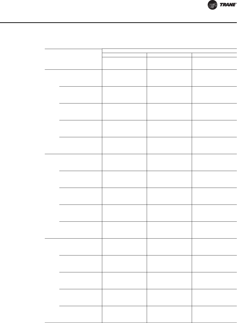
UV-PRC003-EN 37
Performance Data
Table 15. VUV 075, hydronic heating coils A (1-row / 12 fpi), B (2-row / 12 fpi), C (2-row / 16 fpi)
Coil
Entering
Air Temp,
Dry Bulb
(°F)
Entering
Water
Temp (°F)
Flow Rate (gpm)
246
Total
Capacity
(MBh)
Waterside
Temp Drop
(°F)
Total
Capacity
(MBh)
Waterside
Temp Drop
(°F)
Total
Capacity
(MBh)
Waterside
Temp Drop
(°F)
A50 120 19.7 19.0 22.9 11.1 24.3 7.9
140 27.5 26.8 32.1 15.7 34.1 11.1
160 35.5 34.8 41.4 20.4 43.9 14.4
180 43.5 42.8 50.8 25.1 53.7 17.7
55 120 18.6 17.9 21.7 10.5 23.0 7.4
140 26.0 25.3 30.4 14.9 32.2 10.5
160 33.5 32.8 39.2 19.3 41.5 13.6
180 41.2 40.5 48.0 23.7 50.8 16.7
60 120 17.5 16.8 20.4 9.9 21.7 7.0
140 24.6 23.9 28.7 14.0 30.4 9.9
160 31.6 30.9 36.9 18.1 39.2 12.8
180 38.8 38.1 45.3 22.3 47.9 15.7
65 120 16.5 15.8 19.2 9.3 20.4 6.6
140 23.1 22.4 26.9 13.1 28.6 9.3
160 29.7 29.0 34.7 17.0 36.8 12.0
180 36.5 35.8 42.6 21.0 45.1 14.8
70 120 15.4 14.7 18.0 8.7 19.1 6.1
140 21.6 20.9 25.2 12.3 26.7 8.7
160 27.8 27.1 32.5 15.9 34.4 11.2
180 34.2 33.5 39.8 19.6 42.2 13.8
B50 120 27.3 26.6 34.4 16.9 37.6 12.3
140 38.4 37.7 48.5 23.9 52.9 17.4
160 49.7 49.0 62.7 31.0 68.2 22.5
180 61.2 60.5 77.0 38.2 83.7 27.7
55 120 25.9 25.2 32.5 15.9 35.5 11.6
140 36.3 35.6 45.9 22.6 50.0 16.4
160 47.0 46.3 59.3 29.3 64.6 21.3
180 57.9 57.2 72.8 36.1 79.2 26.2
60 120 24.4 23.7 30.7 15.0 33.5 10.9
140 34.3 33.6 43.3 21.3 47.2 15.5
160 44.4 43.7 55.9 27.6 60.9 20.1
180 54.6 53.9 68.7 34.0 74.7 24.7
65 120 22.9 22.2 28.9 14.1 31.5 10.3
140 32.2 31.5 40.7 20.0 44.4 14.6
160 41.7 41.0 52.6 26.0 57.3 18.9
180 51.4 50.7 64.6 32.0 70.2 23.2
70 120 21.5 20.8 27.0 13.2 29.5 9.6
140 30.1 29.4 38.1 18.7 41.5 13.6
160 39.0 38.3 49.2 24.3 53.6 17.6
180 48.1 47.4 60.4 29.9 65.7 21.7
C50 120 28.3 27.6 36.1 17.7 39.5 12.9
140 39.9 39.2 50.9 25.1 55.5 18.3
160 51.7 51.0 65.7 32.5 71.6 23.6
180 63.6 62.9 80.7 40.0 87.8 29.0
55 120 26.8 26.1 34.2 16.8 37.3 12.2
140 37.7 37.0 48.1 23.7 52.5 17.3
160 48.9 48.2 62.2 30.8 67.8 22.4
180 60.2 59.5 76.3 37.8 83.1 27.5
60 120 25.3 24.6 32.2 15.8 35.2 11.5
140 35.6 34.9 45.4 22.4 49.5 16.3
160 46.1 45.4 58.7 29.0 63.9 21.1
180 56.8 56.1 72.0 35.7 78.4 25.9
65 120 23.8 23.1 30.3 14.8 33.1 10.8
140 33.5 32.8 42.7 21.0 46.6 15.3
160 43.3 42.6 55.1 27.2 60.1 19.8
180 53.4 52.7 67.7 33.5 73.7 24.3
70 120 22.2 21.5 28.3 13.8 31.0 10.1
140 31.3 30.6 39.9 19.6 43.6 14.3
160 40.6 39.9 51.6 25.5 56.2 18.5
180 50.0 49.3 63.4 31.4 68.9 22.7
Heating - 075 - Coil A, B, C
UV-PRC003-EN.book Page 37 Tuesday, June 4, 2013 8:59 PM
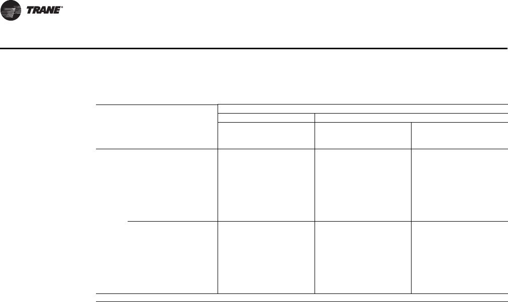
38 UV-PRC003-EN
Performance Data
Table 16. VUV 075, steam heating coil K (low-capacity), L (high-capacity)
Size Coil
Entering
Air Temp,
Dry Bulb
(°F)
Steam Pressure (psig)
51015
Total
Capacity
(MBh)
Airside
Temp Rise
(°F)
Total
Capacity
(MBh)
Airside
Temp Rise
(°F)
Total
Capacity
(MBh)
Airside
Temp Rise
(°F)
750 K 0 68.7 84.8 72.3 89.2 75.3 93.0
10 65.7 81.1 69.3 85.5 72.3 89.2
20 62.7 77.4 66.2 81.8 69.3 85.5
30 59.7 73.6 63.2 78.0 66.3 81.8
40 56.6 69.9 60.2 74.3 63.2 78.1
50 53.6 66.2 57.1 70.6 60.2 74.3
60 50.6 62.4 54.1 66.8 57.2 70.6
70 47.5 58.7 51.1 63.1 54.2 66.9
L 0 81.2 100.2 85.4 105.4 89.0 109.9
10 77.6 95.8 81.8 101.0 85.4 105.4
20 74.0 91.4 78.2 96.6 81.8 101.0
30 70.4 87.0 74.7 92.2 78.3 96.6
40 66.9 82.6 71.1 87.8 74.7 92.2
50 63.3 78.2 67.5 83.4 71.1 87.8
60 59.7 73.7 63.9 78.9 67.5 83.4
70 56.2 69.4 60.4 74.6 64.0 79.0
psig = Steam Pressure (lb/in.2 gage)
Heating - 075 - Coil K, L
UV-PRC003-EN.book Page 38 Tuesday, June 4, 2013 8:59 PM

UV-PRC003-EN 39
Performance Data
Table 17. VUV 100, cooling coil E, 3-row / 16 fpi
Entering
Wet Bulb
Temp
(°F)
Entering
Dry Bulb
Temp
(°F)
Entering
Water
Temp
(°F)
Flow Rate (gpm)
24610
Total
Capacity
(MBh)
Sensible
Capacity
(MBh)
ΔT
(°F)
Total
Capacity
(MBh)
Sensible
Capacity
(MBh)
ΔT
(°F)
Total
Capacity
(MBh)
Sensible
Capacity
(MBh)
ΔT
(°F)
Total
Capacity
(MBh)
Sensible
Capacity
(MBh)
ΔT
(°F)
61 70 40 12.6 11.3 13.5 18.6 14.3 9.7 23.2 16.1 8.0 29.2 18.1 6.0
42 12.0 11.0 12.9 17.7 13.9 9.3 22.0 15.6 7.6 27.6 17.5 5.7
45 11.0 10.4 11.9 16.2 13.4 8.6 20.2 14.9 7.0 25.1 16.6 5.2
48 9.9 9.7 10.9 14.7 12.7 7.8 18.3 14.2 6.4 22.5 15.6 4.7
75 40 13.7 13.7 14.7 20.3 18.5 10.6 25.3 20.8 8.7 31.9 23.5 6.6
42 13.1 13.1 14.0 19.3 18.1 10.1 24.0 20.2 8.3 30.1 22.7 6.2
45 12.0 12.0 12.9 17.7 17.3 9.3 22.0 19.3 7.6 27.4 21.5 5.7
48 10.9 10.9 11.8 16.1 16.1 8.5 19.9 18.4 6.9 24.6 20.3 5.1
80 40 15.2 15.2 16.2 22.5 22.4 11.7 28.1 25.2 9.7 35.4 28.5 7.3
42 14.5 14.5 15.4 21.4 21.4 11.1 26.7 24.5 9.2 33.4 27.5 6.9
45 13.4 13.4 14.3 19.7 19.7 10.3 24.4 23.4 8.4 30.4 26.0 6.3
48 12.0 12.0 12.9 17.8 17.8 9.4 22.1 22.1 7.7 27.3 24.5 5.6
85 40 17.0 17.0 17.9 25.1 25.1 13.0 31.4 29.3 10.8 39.5 33.1 8.1
42 16.2 16.2 17.1 23.9 23.9 12.4 29.8 28.5 10.2 37.3 31.9 7.6
45 14.9 14.9 15.8 21.9 21.9 11.4 27.3 27.2 9.4 33.9 30.2 7.0
48 13.4 13.4 14.3 19.9 19.9 10.4 24.7 24.7 8.5 30.4 28.5 6.3
90 40 19.0 19.0 19.9 28.0 28.0 14.4 35.0 33.2 12.0 44.0 37.5 9.0
42 18.1 18.1 19.0 26.6 26.6 13.8 33.2 32.3 11.4 41.5 36.2 8.5
45 16.6 16.6 17.5 24.4 24.4 12.7 30.4 30.4 10.4 37.8 34.3 7.7
48 15.0 15.0 15.9 22.2 22.2 11.5 27.5 27.5 9.5 33.9 32.3 7.0
67 75 40 17.2 12.2 18.1 25.4 15.4 13.1 31.7 17.3 10.9 39.9 19.5 8.2
42 16.4 11.8 17.3 24.1 15.0 12.5 30.1 16.8 10.3 37.7 18.8 7.7
45 15.1 11.2 16.0 22.2 14.4 11.5 27.6 16.1 9.5 34.2 17.8 7.0
48 13.6 10.5 14.5 20.1 13.7 10.5 24.9 15.3 8.6 30.8 16.8 6.3
80 40 18.0 15.8 18.9 26.6 19.9 13.8 33.3 22.4 11.4 41.9 25.3 8.6
42 17.2 15.3 18.1 25.3 19.4 13.1 31.5 21.8 10.8 39.5 24.4 8.1
45 15.8 14.5 16.7 23.3 18.6 12.1 28.9 20.8 9.9 35.9 23.1 7.4
48 14.2 13.6 15.1 21.1 17.7 11.0 26.2 19.8 9.0 32.3 21.8 6.6
85 40 19.2 19.2 20.1 28.3 24.3 14.6 35.4 27.3 12.1 44.6 30.8 9.1
42 18.3 18.3 19.2 26.9 23.7 13.9 33.6 26.6 11.5 42.1 29.8 8.6
45 16.8 16.8 17.7 24.8 22.7 12.8 30.8 25.4 10.6 38.2 28.2 7.8
48 15.2 15.2 16.1 22.4 21.6 11.7 27.9 24.1 9.6 34.4 26.6 7.1
90 40 20.6 20.6 21.5 30.4 28.6 15.7 38.0 32.1 13.0 47.8 36.3 9.7
42 19.6 19.6 20.5 28.9 27.9 14.9 36.0 31.2 12.3 45.1 35.0 9.2
45 18.1 18.1 19.0 26.6 26.6 13.7 33.0 29.8 11.3 41.0 33.1 8.4
48 16.3 16.3 17.2 24.1 24.1 12.5 29.9 28.4 10.3 36.9 31.2 7.6
70 75 40 19.6 10.7 20.5 28.9 13.5 14.9 36.1 15.1 12.3 45.4 17.1 9.3
42 18.7 10.4 19.6 27.5 13.1 14.2 34.2 14.7 11.7 42.9 16.5 8.8
45 17.1 9.8 18.0 25.2 12.6 13.1 31.4 14.1 10.8 39.0 15.6 8.0
48 15.4 9.2 16.4 22.9 12.0 11.9 28.4 13.4 9.8 35.0 14.7 7.2
80 40 20.1 14.3 21.0 29.7 18.1 15.3 37.1 20.3 12.7 46.6 23.0 9.5
42 19.2 13.9 20.1 28.2 17.6 14.6 35.2 19.8 12.0 44.0 22.1 9.0
45 17.6 13.2 18.5 25.9 16.9 13.4 32.2 18.9 11.0 40.0 21.0 8.2
48 15.9 12.3 16.8 23.5 16.1 12.2 29.2 18.0 10.0 36.0 19.8 7.4
85 40 21.0 17.9 21.9 31.0 22.7 15.9 38.7 25.5 13.2 48.7 28.7 9.9
42 20.0 17.4 20.9 29.4 22.1 15.2 36.7 24.8 12.5 45.9 27.7 9.4
45 18.4 16.5 19.3 27.0 21.2 14.0 33.6 23.7 11.5 41.8 26.3 8.5
48 16.6 15.4 17.5 24.5 20.1 12.7 30.4 22.5 10.4 37.5 24.8 7.7
90 40 22.1 21.5 23.0 32.6 27.1 16.8 40.8 30.5 13.9 51.3 34.4 10.4
42 21.1 20.9 22.0 31.0 26.5 16.0 38.7 29.6 13.2 48.4 33.2 9.9
45 19.4 19.4 20.3 28.5 25.4 14.7 35.4 28.3 12.1 44.0 31.4 9.0
48 17.5 17.5 18.4 25.8 24.1 13.4 32.1 26.9 11.0 39.6 29.7 8.1
Heating - 100 - Coil E
UV-PRC003-EN.book Page 39 Tuesday, June 4, 2013 8:59 PM

40 UV-PRC003-EN
Performance Data
Table 18. VUV 100, cooling coil F, 4-row / 12 fpi
Entering
Wet Bulb
Temp
(°F)
Entering
Dry Bulb
Temp
(°F)
Entering
Water
Temp
(°F)
Flow Rate (gpm)
24610
Total
Capacity
(MBh)
Sensible
Capacity
(MBh)
ΔT
(°F)
Total
Capacity
(MBh)
Sensible
Capacity
(MBh)
ΔT
(°F)
Total
Capacity
(MBh)
Sensible
Capacity
(MBh)
ΔT
(°F)
Total
Capacity
(MBh)
Sensible
Capacity
(MBh)
ΔT
(°F)
61 70 40 12.4 11.3 13.3 19.3 14.1 10.1 24.1 15.8 8.3 29.7 17.9 6.1
42 11.8 11.0 12.7 18.4 13.8 9.6 22.8 15.4 7.9 28.0 17.3 5.8
45 10.8 10.4 11.7 16.9 13.2 8.9 20.9 14.7 7.3 25.5 16.3 5.3
48 9.7 9.7 10.6 15.3 12.6 8.1 19.0 14.0 6.6 23.0 15.3 4.8
75 40 13.6 13.6 14.5 21.1 18.3 11.0 26.2 20.5 9.0 32.3 23.2 6.7
42 12.9 12.9 13.8 20.0 17.8 10.5 24.9 19.9 8.6 30.6 22.4 6.3
45 11.7 11.7 12.7 18.4 17.1 9.7 22.8 19.0 7.9 27.9 21.1 5.8
48 10.6 10.6 11.5 16.7 16.3 8.8 20.7 18.1 7.2 25.1 19.9 5.2
80 40 15.0 15.0 15.9 23.4 22.2 12.1 29.1 24.8 10.0 35.9 28.1 7.4
42 14.3 14.3 15.2 22.2 21.6 11.6 27.6 24.1 9.5 33.9 27.1 7.0
45 13.0 13.0 13.9 20.4 20.4 10.7 25.3 23.0 8.7 30.9 25.5 6.4
48 11.7 11.7 12.6 18.5 18.5 9.7 23.0 21.9 8.0 27.8 24.0 5.7
85 40 16.8 16.8 17.7 26.1 25.8 13.5 32.5 28.9 11.1 40.0 32.7 8.2
42 15.9 15.9 16.8 24.8 24.8 12.8 30.8 28.0 10.6 37.8 31.5 7.7
45 14.5 14.5 15.4 22.8 22.8 11.8 28.3 26.8 9.7 34.5 29.7 7.1
48 13.1 13.1 14.0 20.7 20.7 10.8 25.7 25.5 8.9 31.0 28.0 6.4
90 40 18.7 18.7 19.6 29.1 29.1 15.0 36.2 32.8 12.4 44.6 37.1 9.1
42 17.7 17.7 18.6 27.6 27.6 14.3 34.4 31.8 11.8 42.2 35.7 8.6
45 16.2 16.2 17.1 25.4 25.4 13.1 31.5 30.3 10.8 38.4 33.7 7.9
48 14.6 14.6 15.5 23.0 23.0 12.0 28.6 28.6 9.8 34.6 31.7 7.1
67 75 40 17.0 12.2 17.9 26.4 15.2 13.6 32.8 17.0 11.2 40.5 19.3 8.3
42 16.1 11.8 17.0 25.1 14.8 13.0 31.1 16.5 10.7 38.2 18.6 7.8
45 14.7 11.2 15.6 23.0 14.2 12.0 28.6 15.8 9.8 34.8 17.5 7.1
48 13.2 10.6 14.1 20.9 13.5 10.9 25.9 15.0 8.9 31.4 16.5 6.5
80 40 17.8 15.7 18.7 27.7 19.7 14.3 34.4 22.1 11.8 42.5 25.0 8.7
42 16.9 15.3 17.8 26.3 19.2 13.6 32.7 21.4 11.2 40.1 24.1 8.2
45 15.4 14.6 16.3 24.1 18.4 12.5 30.0 20.4 10.3 36.6 22.7 7.5
48 13.9 13.7 14.8 21.9 17.5 11.4 27.2 19.4 9.4 32.9 21.3 6.8
85 40 18.9 18.9 19.8 29.5 24.0 15.2 36.7 26.9 12.5 45.2 30.5 9.2
42 18.0 18.0 18.9 28.0 23.4 14.4 34.8 26.1 11.9 42.7 29.4 8.7
45 16.4 16.4 17.3 25.7 22.4 13.3 31.9 24.9 10.9 38.9 27.7 8.0
48 14.8 14.8 15.7 23.3 21.4 12.1 29.0 23.7 10.0 35.0 26.1 7.2
90 40 20.3 20.3 21.2 31.6 28.2 16.3 39.3 31.7 13.4 48.5 35.8 9.9
42 19.3 19.3 20.2 30.0 27.5 15.5 37.3 30.7 12.7 45.8 34.5 9.3
45 17.6 17.6 18.5 27.6 26.3 14.2 34.3 29.3 11.7 41.8 32.5 8.5
48 15.9 15.9 16.8 25.0 25.0 13.0 31.1 27.9 10.7 37.6 30.6 7.7
70 75 40 19.3 10.6 20.2 30.0 13.3 15.5 37.4 14.9 12.8 46.1 16.9 9.4
42 18.3 10.3 19.2 28.5 13.0 14.7 35.5 14.5 12.1 43.5 16.3 8.9
45 16.7 9.8 17.6 26.2 12.4 13.6 32.5 13.8 11.1 39.7 15.3 8.1
48 15.1 9.3 16.0 23.8 11.8 12.3 29.5 13.1 10.1 35.7 14.4 7.3
80 40 19.8 14.3 20.7 30.8 17.9 15.9 38.4 20.0 13.1 47.3 22.7 9.6
42 18.8 13.9 19.7 29.3 17.4 15.1 36.4 19.4 12.4 44.7 21.8 9.1
45 17.2 13.2 18.1 26.9 16.7 13.9 33.4 18.6 11.4 40.7 20.6 8.3
48 15.5 12.5 16.4 24.4 15.9 12.7 30.3 17.7 10.4 36.7 19.4 7.5
85 40 20.7 17.9 21.6 32.2 22.4 16.5 40.0 25.1 13.7 49.4 28.4 10.1
42 19.6 17.4 20.5 30.6 21.8 15.7 38.0 24.4 13.0 46.7 27.4 9.5
45 17.9 16.6 18.8 28.1 20.9 14.5 34.9 23.2 11.9 42.5 25.8 8.7
48 16.1 15.6 17.0 25.5 19.9 13.2 31.6 22.1 10.8 38.3 24.3 7.8
90 40 21.8 21.4 22.7 33.9 26.8 17.4 42.2 30.1 14.4 52.0 34.0 10.6
42 20.7 20.7 21.6 32.2 26.1 16.6 40.1 29.2 13.7 49.2 32.8 10.0
45 18.9 18.9 19.8 29.6 25.0 15.3 36.8 27.8 12.6 44.8 30.9 9.1
48 17.0 17.0 17.9 26.9 23.9 13.9 33.4 26.5 11.4 40.3 29.1 8.2
Cooling - 100 - Coil F
UV-PRC003-EN.book Page 40 Tuesday, June 4, 2013 8:59 PM

UV-PRC003-EN 41
Performance Data
Table 19. VUV 100, cooling coil G, 4-row / 16 fpi
Entering
Wet Bulb
Temp
(°F)
Entering
Dry Bulb
Temp
(°F)
Entering
Water
Temp
(°F)
Flow Rate (gpm)
24610
Total
Capacity
(MBh)
Sensible
Capacity
(MBh)
ΔT
(°F)
Total
Capacity
(MBh)
Sensible
Capacity
(MBh)
ΔT
(°F)
Total
Capacity
(MBh)
Sensible
Capacity
(MBh)
ΔT
(°F)
Total
Capacity
(MBh)
Sensible
Capacity
(MBh)
ΔT
(°F)
61 70 40 15.0 13.1 15.9 22.9 17.1 11.9 28.8 19.4 9.9 35.9 22.3 7.4
42 14.2 12.7 15.1 21.7 16.5 11.3 27.2 18.7 9.4 33.7 21.3 6.9
45 13.0 12.0 13.9 19.7 15.7 10.3 24.6 17.7 8.5 30.3 19.9 6.2
48 11.7 11.3 12.6 17.8 14.8 9.3 22.1 16.6 7.7 26.8 18.5 5.5
75 40 16.3 16.3 17.2 25.0 22.1 13.0 31.4 25.2 10.8 39.1 28.9 8.0
42 15.5 15.5 16.4 23.6 21.4 12.3 29.6 24.3 10.2 36.7 27.6 7.5
45 14.1 14.1 15.0 21.5 20.3 11.2 26.9 22.9 9.3 33.0 25.8 6.8
48 12.8 12.8 13.7 19.4 19.2 10.1 24.1 21.6 8.3 29.2 24.0 6.0
80 40 18.1 18.1 19.0 27.7 26.8 14.3 34.9 30.5 11.9 43.4 34.9 8.9
42 17.2 17.2 18.1 26.2 25.9 13.6 32.9 29.4 11.3 40.7 33.4 8.3
45 15.7 15.7 16.6 23.9 23.9 12.4 29.8 27.8 10.2 36.6 31.2 7.5
48 14.2 14.2 15.1 21.5 21.5 11.2 26.7 26.1 9.2 32.4 29.0 6.7
85 40 20.2 20.2 21.1 31.0 31.0 15.9 38.9 35.5 13.3 48.4 40.7 9.9
42 19.1 19.1 20.0 29.2 29.2 15.1 36.7 34.2 12.5 45.4 38.9 9.3
45 17.5 17.5 18.4 26.6 26.6 13.8 33.3 32.3 11.4 40.9 36.3 8.4
48 15.8 15.8 16.7 24.0 24.0 12.4 29.8 29.8 10.2 36.2 33.8 7.4
90 40 22.6 22.6 23.5 34.5 34.5 17.7 43.4 40.2 14.8 54.0 46.1 11.0
42 21.3 21.3 22.2 32.6 32.6 16.8 40.9 38.8 13.9 50.7 44.1 10.3
45 19.5 19.5 20.4 29.7 29.7 15.3 37.1 36.6 12.7 45.6 41.1 9.3
48 17.6 17.6 18.5 26.7 26.7 13.8 33.2 33.2 11.4 40.3 38.2 8.2
67 75 40 20.4 14.1 21.4 31.3 18.4 16.1 39.3 20.9 13.4 48.9 24.0 10.0
42 19.3 13.7 20.3 29.6 17.8 15.2 37.1 20.2 12.7 45.9 22.9 9.4
45 17.7 12.9 18.6 26.9 16.9 13.9 33.6 19.0 11.5 41.3 21.4 8.4
48 16.0 12.2 16.9 24.2 16.0 12.6 30.1 17.9 10.3 36.6 19.9 7.5
80 40 21.5 18.3 22.4 32.8 23.8 16.9 41.3 27.1 14.1 51.4 31.0 10.5
42 20.3 17.7 21.2 31.0 23.0 16.0 38.9 26.1 13.3 48.2 29.7 9.8
45 18.5 16.8 19.4 28.3 21.9 14.6 35.3 24.7 12.1 43.3 27.7 8.8
48 16.8 15.8 17.7 25.4 20.7 13.2 31.6 23.2 10.8 38.4 25.8 7.9
85 40 22.8 22.3 23.7 35.0 29.1 17.9 43.9 33.1 14.9 54.7 37.9 11.1
42 21.6 21.6 22.5 33.0 28.1 17.0 41.4 31.9 14.1 51.3 36.2 10.4
45 19.7 19.7 20.6 30.1 26.7 15.5 37.6 30.1 12.8 46.1 33.8 9.4
48 17.8 17.8 18.8 27.1 25.2 14.0 33.6 28.3 11.5 40.9 31.5 8.4
90 40 24.5 24.5 25.4 37.5 34.1 19.2 47.1 38.9 16.0 58.7 44.5 11.9
42 23.2 23.2 24.1 35.4 33.0 18.2 44.4 37.5 15.1 55.0 42.6 11.2
45 21.2 21.2 22.1 32.3 31.4 16.6 40.3 35.4 13.7 49.5 39.8 10.1
48 19.1 19.1 20.1 29.1 29.1 15.0 36.1 33.3 12.3 43.8 37.0 8.9
70 75 40 23.3 12.3 24.2 35.6 16.1 18.3 44.8 18.3 15.2 55.7 21.0 11.3
42 22.0 12.0 22.9 33.6 15.6 17.3 42.2 17.7 14.4 52.3 20.1 10.6
45 20.1 11.3 21.0 30.7 14.8 15.8 38.3 16.7 13.1 47.0 18.7 9.6
48 18.2 10.7 19.1 27.6 14.0 14.3 34.3 15.7 11.7 41.6 17.4 8.5
80 40 23.9 16.6 24.8 36.6 21.6 18.7 46.0 24.6 15.6 57.2 28.2 11.6
42 22.6 16.1 23.5 34.6 20.9 17.7 43.3 23.7 14.7 53.7 27.0 10.9
45 20.7 15.2 21.6 31.5 19.9 16.2 39.3 22.4 13.4 48.3 25.2 9.8
48 18.7 14.3 19.6 28.3 18.8 14.6 35.2 21.1 12.0 42.8 23.4 8.7
85 40 24.9 20.8 25.9 38.2 27.1 19.5 48.0 30.8 16.3 59.7 35.3 12.1
42 23.6 20.1 24.5 36.1 26.2 18.5 45.2 29.7 15.4 56.0 33.8 11.4
45 21.6 19.1 22.5 32.9 24.9 16.9 41.0 28.0 14.0 50.4 31.5 10.3
48 19.5 17.9 20.4 29.6 23.5 15.2 36.7 26.4 12.5 44.6 29.3 9.1
90 40 26.3 24.9 27.2 40.2 32.4 20.6 50.6 36.9 17.2 63.0 42.3 12.8
42 24.9 24.1 25.8 38.0 31.4 19.5 47.7 35.6 16.2 59.1 40.5 12.0
45 22.7 22.7 23.6 34.6 29.8 17.8 43.2 33.6 14.7 53.1 37.8 10.8
48 20.5 20.5 21.5 31.2 28.1 16.0 38.7 31.6 13.2 47.0 35.1 9.6
Cooling - 100 - Coil G
UV-PRC003-EN.book Page 41 Tuesday, June 4, 2013 8:59 PM

42 UV-PRC003-EN
Performance Data
Table 20. VUV 100, cooling coil H, 3-row / 16 fpi
Entering
Wet Bulb
Temp
(°F)
Entering
Dry Bulb
Temp
(°F)
Entering
Water
Temp
(°F)
Flow Rate (gpm)
24610
Total
Capacity
(MBh)
Sensible
Capacity
(MBh)
ΔT
(°F)
Total
Capacity
(MBh)
Sensible
Capacity
(MBh)
ΔT
(°F)
Total
Capacity
(MBh)
Sensible
Capacity
(MBh)
ΔT
(°F)
Total
Capacity
(MBh)
Sensible
Capacity
(MBh)
ΔT
(°F)
61 70 40 14.0 12.3 14.9 21.6 16.1 11.3 27.0 18.2 9.3 32.8 20.6 6.7
42 13.2 11.9 14.1 20.4 15.5 10.7 25.4 17.5 8.8 30.7 19.7 6.3
45 12.1 11.3 13.1 18.6 14.7 9.8 23.0 16.5 8.0 27.5 18.4 5.7
48 11.0 10.7 11.9 16.8 13.9 8.9 20.6 15.6 7.2 24.2 17.1 5.0
75 40 15.2 15.2 16.1 23.6 20.8 12.3 29.5 23.6 10.1 35.8 26.7 7.3
42 14.4 14.4 15.3 22.3 20.1 11.6 27.7 22.7 9.6 33.5 25.5 6.9
45 13.2 13.2 14.2 20.3 19.1 10.6 25.1 21.4 8.7 30.0 23.8 6.2
48 12.0 12.0 12.9 18.3 18.1 9.6 22.5 20.2 7.8 26.4 22.1 5.5
80 40 16.9 16.9 17.8 26.2 25.2 13.5 32.7 28.5 11.2 39.7 32.3 8.1
42 16.0 16.0 16.9 24.7 24.4 12.8 30.8 27.5 10.6 37.1 30.9 7.6
45 14.7 14.7 15.6 22.6 22.6 11.7 27.9 25.9 9.6 33.3 28.8 6.8
48 13.4 13.4 14.3 20.3 20.3 10.6 24.9 24.4 8.6 29.3 26.8 6.0
85 40 18.9 18.9 19.8 29.2 29.2 15.1 36.5 33.2 12.5 44.3 37.6 9.0
42 17.9 17.9 18.8 27.6 27.6 14.3 34.3 32.0 11.7 41.4 36.0 8.5
45 16.4 16.4 17.3 25.2 25.2 13.0 31.1 30.2 10.7 37.1 33.6 7.6
48 14.9 14.9 15.8 22.7 22.7 11.8 27.8 27.8 9.6 32.7 31.2 6.7
90 40 21.0 21.0 21.9 32.6 32.6 16.7 40.6 37.6 13.9 49.4 42.6 10.1
42 19.9 19.9 20.8 30.8 30.8 15.8 38.3 36.2 13.1 46.2 40.8 9.4
45 18.3 18.3 19.2 28.1 28.1 14.5 34.7 34.2 11.9 41.4 38.0 8.5
48 16.6 16.6 17.5 25.3 25.3 13.1 31.0 31.0 10.6 36.4 35.3 7.5
67 75 40 19.1 13.3 20.0 29.5 17.3 15.2 36.9 19.6 12.6 44.8 22.2 9.1
42 18.1 12.8 19.0 27.9 16.7 14.4 34.7 18.9 11.9 41.9 21.2 8.6
45 16.6 12.2 17.5 25.4 15.9 13.2 31.4 17.8 10.8 37.5 19.8 7.7
48 15.1 11.5 16.0 22.9 15.0 11.9 28.1 16.7 9.7 33.0 18.4 6.8
80 40 20.0 17.2 20.9 31.0 22.4 15.9 38.7 25.3 13.2 47.0 28.7 9.6
42 19.0 16.6 19.9 29.3 21.6 15.1 36.4 24.4 12.4 43.9 27.5 9.0
45 17.4 15.8 18.3 26.7 20.5 13.8 33.0 23.0 11.3 39.4 25.6 8.1
48 15.8 14.8 16.7 24.1 19.4 12.5 29.5 21.7 10.1 34.7 23.8 7.1
85 40 21.3 20.9 22.2 33.0 27.3 16.9 41.2 30.9 14.0 50.0 35.0 10.2
42 20.2 20.2 21.1 31.2 26.4 16.0 38.8 29.8 13.2 46.8 33.5 9.5
45 18.5 18.5 19.4 28.4 25.1 14.7 35.1 28.1 12.0 41.9 31.3 8.6
48 16.8 16.8 17.7 25.6 23.7 13.3 31.4 26.4 10.8 36.9 29.1 7.6
90 40 22.8 22.8 23.7 35.4 32.1 18.1 44.2 36.3 15.0 53.6 41.2 10.9
42 21.7 21.7 22.6 33.4 31.0 17.2 41.6 35.0 14.2 50.2 39.4 10.2
45 19.9 19.9 20.8 30.5 29.5 15.7 37.7 33.1 12.9 45.0 36.7 9.2
48 18.1 18.1 19.0 27.5 27.5 14.2 33.7 31.1 11.5 39.6 34.2 8.1
70 75 40 21.7 11.6 22.6 33.6 15.1 17.3 42.0 17.1 14.3 50.9 19.4 10.4
42 20.6 11.2 21.5 31.8 14.6 16.3 39.5 16.5 13.5 47.7 18.6 9.7
45 18.9 10.7 19.8 29.0 13.9 14.9 35.8 15.6 12.2 42.7 17.3 8.7
48 17.1 10.0 18.1 26.1 13.1 13.5 32.0 14.7 11.0 37.6 16.1 7.7
80 40 22.3 15.6 23.2 34.5 20.3 17.7 43.1 23.0 14.7 52.3 26.1 10.6
42 21.1 15.1 22.0 32.6 19.7 16.8 40.6 22.2 13.8 49.0 24.9 10.0
45 19.4 14.3 20.3 29.7 18.7 15.3 36.8 20.9 12.6 43.9 23.3 9.0
48 17.6 13.5 18.5 26.8 17.6 13.9 32.9 19.7 11.3 38.6 21.6 7.9
85 40 23.3 19.5 24.2 36.0 25.5 18.5 45.0 28.8 15.3 54.6 32.7 11.1
42 22.0 18.9 23.0 34.0 24.6 17.5 42.4 27.8 14.4 51.1 31.2 10.4
45 20.2 17.9 21.1 31.0 23.4 16.0 38.4 26.2 13.1 45.8 29.1 9.3
48 18.4 16.9 19.3 28.0 22.1 14.4 34.3 24.6 11.7 40.3 27.1 8.2
90 40 24.5 23.4 25.4 38.0 30.5 19.4 47.4 34.5 16.1 57.6 39.1 11.7
42 23.2 22.6 24.1 35.9 29.5 18.4 44.6 33.3 15.2 53.9 37.4 11.0
45 21.3 21.3 22.2 32.7 28.0 16.8 40.4 31.4 13.8 48.2 34.9 9.8
48 19.4 19.4 20.3 29.5 26.4 15.2 36.2 29.5 12.4 42.5 32.4 8.7
Cooling - 100 - Coil H
UV-PRC003-EN.book Page 42 Tuesday, June 4, 2013 8:59 PM

UV-PRC003-EN 43
Performance Data
Table 21. VUV 100, cooling coil J (DX)
Size EWB
Suct
Temp
EDB = 70°F EDB = 75°F EDB = 80°F EDB = 85°F
TC SC LDB LWB TC SC LDB LWB TC SC LDB LWB TC SC LDB LWB
1000 61 40 29.1 19.1 52.1 50.5 31.8 25.3 51.3 49.3 35.2 31.0 51.0 47.9 39.4 36.3 51.0 46.0
45 24.4 17.4 53.7 52.3 26.7 23.0 53.5 51.4 29.5 28.1 53.7 50.2 33.0 33.0 54.1 48.7
50 19.7 15.6 55.4 54.1 21.5 20.7 55.6 53.4 23.8 23.8 57.7 52.5 26.6 26.6 60.1 51.3
64 40 34.6 16.5 54.6 52.1 36.4 23.2 53.3 51.4 38.7 29.5 52.4 50.4 41.6 35.5 51.8 49.1
45 29.0 15.0 56.0 54.2 30.5 21.1 55.2 53.6 32.5 26.8 54.9 52.8 34.9 32.2 54.9 51.8
50 23.4 13.5 57.4 56.3 24.6 19.0 57.2 55.8 26.2 24.1 57.4 55.2 28.2 28.2 58.6 54.4
67 40 40.9 13.2 57.6 53.7 42.2 20.3 56.0 53.1 43.7 27.1 54.6 52.5 45.7 33.5 53.6 51.6
45 34.3 12.0 58.8 56.1 35.4 18.5 57.7 55.6 36.7 24.6 57.0 55.1 38.3 30.5 56.4 54.4
50 27.7 10.8 59.9 58.4 28.5 16.6 59.5 58.1 29.6 22.2 59.2 57.6 30.9 27.4 59.3 57.1
70 40 48.9 16.8 59.3 54.8 50.0 23.8 57.7 54.3 51.3 30.6 56.4 53.7
45 41.0 15.2 60.8 57.6 41.9 21.6 59.8 57.2 43.0 27.8 59.0 56.7
50 33.1 13.7 62.2 60.2 33.8 19.5 61.7 60.0 34.7 25.0 61.6 59.6
73 40 57.2 19.9 61.4 56.0 58.1 26.9 59.8 55.6
45 47.9 18.1 63.1 59.2 48.7 24.4 62.2 58.9
50 38.7 16.2 64.8 62.2 39.3 22.0 64.4 61.9
EDB = Entering Air Temperature, Dry Bulb (°F)
EWB = Entering Air Temperature, Wet Bulb (°F)
TC = Total Capacity (MBh)
SC = Sensible Capacity (MBh)
LDB = Leaving Air Temperature, Dry Bulb (°F)
LWB = Leaving Air Temperature, Wet Bulb (°F)
Table 22. Airflow correction (% of design airflow)
%
Total Capacity
(MBh)
Sensible Capacity
(MBh)
120 1.025 1.105
110 1.012 1.051
100 1.000 0.998
90 0.987 0.945
80 0.974 0.892
Table 23. Airflow through coil J
Unit Model 1000
Rated cfm 989
Cooling - 100 - Coil (DX)
UV-PRC003-EN.book Page 43 Tuesday, June 4, 2013 8:59 PM
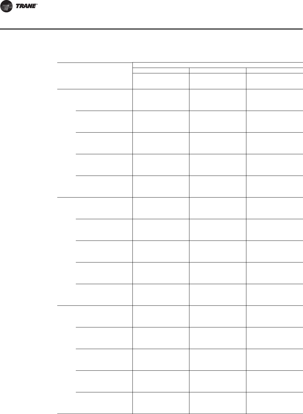
44 UV-PRC003-EN
Performance Data
Table 24. VUV 100, hydronic heating coils A (1-row / 12 fpi), B (2-row / 12 fpi), C (2-row / 16 fpi)
Coil
Entering Air
Temp, Dry
Bulb (°F)
Entering
Water
Temp (°F)
Flow Rate (gpm)
246
Total
Capacity
(MBh)
Waterside
Temp Drop
(°F)
Total
Capacity
(MBh)
Waterside
Temp Drop
(°F)
Total
Capacity
(MBh)
Waterside
Temp Drop
(°F)
A50 120 23.8 22.9 28.4 13.7 30.4 9.8
140 33.3 32.4 39.7 19.4 42.5 13.9
160 42.9 42.0 51.2 25.1 54.7 17.9
180 52.6 51.7 62.6 30.8 66.9 22.0
55 120 22.5 21.6 26.8 12.9 28.7 9.3
140 31.5 30.6 37.6 18.3 40.2 13.1
160 40.6 39.7 48.4 23.7 51.7 16.9
180 49.7 48.8 59.2 29.1 63.3 20.8
60 120 21.2 20.3 25.3 12.2 27.1 8.7
140 29.7 28.8 35.5 17.3 37.9 12.3
160 38.3 37.4 45.6 22.3 48.8 16.0
180 46.9 46.0 55.9 27.5 59.7 19.6
65 120 20.0 19.1 23.8 11.4 25.5 8.2
140 27.9 27.0 33.3 16.2 35.6 11.6
160 36.0 35.1 42.9 21.0 45.9 15.0
180 44.1 43.2 52.5 25.8 56.1 18.4
70 120 18.7 17.8 22.3 10.7 23.8 7.6
140 26.1 25.2 31.2 15.1 33.4 10.8
160 33.7 32.8 40.2 19.6 42.9 14.0
180 41.3 40.4 49.2 24.1 52.5 17.2
B50 120 32.6 31.7 43.1 21.1 47.6 15.6
140 46.2 45.3 60.7 29.9 66.9 22.0
160 59.8 58.9 78.3 38.7 86.4 28.5
180 73.3 72.4 96.0 47.5 105.9 35.0
55 120 30.8 29.9 40.8 19.9 45.1 14.7
140 43.7 42.8 57.4 28.2 63.3 20.8
160 56.6 55.7 74.1 36.6 81.7 26.9
180 69.3 68.4 90.8 44.9 100.1 33.1
60 120 29.1 28.2 38.5 18.8 42.5 13.9
140 41.3 40.4 54.2 26.6 59.7 19.6
160 53.4 52.5 69.9 34.5 77.1 25.4
180 65.4 64.5 85.6 42.3 94.5 31.2
65 120 27.3 26.4 36.2 17.6 40.0 13.0
140 38.8 37.9 50.9 25.0 56.2 18.4
160 50.2 49.3 65.7 32.4 72.5 23.9
180 61.5 60.6 80.5 39.8 88.8 29.3
70 120 25.6 24.7 33.9 16.5 37.4 12.2
140 36.3 35.4 47.6 23.3 52.6 17.2
160 47.0 46.1 61.5 30.3 67.8 22.3
180 57.5 56.6 75.3 37.2 83.1 27.4
C50 120 33.7 32.8 45.4 22.2 50.2 16.4
140 47.9 47.0 63.8 31.4 70.6 23.2
160 62.0 61.1 82.4 40.7 91.0 30.0
180 75.9 75.0 100.9 50.0 111.6 36.9
55 120 31.9 31.0 42.9 21.0 47.5 15.5
140 45.3 44.4 60.4 29.7 66.8 22.0
160 58.6 57.7 77.9 38.5 86.1 28.4
180 71.8 70.9 95.4 47.2 105.5 34.9
60 120 30.1 29.2 40.5 19.8 44.8 14.6
140 42.7 41.8 57.0 28.0 63.0 20.7
160 55.3 54.4 73.5 36.3 81.2 26.8
180 67.8 66.9 90.0 44.5 99.5 32.9
65 120 28.3 27.4 38.1 18.6 42.1 13.7
140 40.1 39.2 53.5 26.3 59.2 19.4
160 52.0 51.1 69.1 34.1 76.4 25.2
180 63.7 62.8 84.6 41.8 93.6 30.9
70 120 26.5 25.6 35.6 17.3 39.4 12.8
140 37.6 36.7 50.1 24.6 55.4 18.2
160 48.6 47.7 64.7 31.9 71.5 23.5
180 59.6 58.7 79.2 39.1 87.6 28.9
Heating - 100 - Coil A, B, C
UV-PRC003-EN.book Page 44 Tuesday, June 4, 2013 8:59 PM

UV-PRC003-EN 45
Performance Data
Table 25. VUV 100, steam heating coils K (low-capacity), L (high-capacity)
Size Coil
Entering
Air Temp,
Dry Bulb
(°F)
Steam Pressure (psig)
51015
Total
Capacity
(MBh)
Airside
Temp Rise
(°F)
Total
Capacity
(MBh)
Airside
Temp Rise
(°F)
Total
Capacity
(MBh)
Airside
Temp Rise
(°F)
1000 K 0 92.9 86.0 97.7 90.5 101.8 94.3
10 88.8 82.2 93.6 86.7 97.7 90.5
20 84.7 78.4 89.5 82.9 93.6 86.7
30 80.6 74.6 85.4 79.1 89.5 82.9
40 76.5 70.8 81.3 75.3 85.4 79.1
50 72.4 67.0 77.2 71.5 81.3 75.3
60 68.3 63.3 73.1 67.7 77.3 71.5
70 64.3 59.5 69.1 64.0 73.2 67.8
L 0 131.0 121.3 137.8 127.6 143.6 132.9
10 125.3 116.0 132.0 122.3 137.8 127.6
20 119.5 110.6 126.3 116.9 132.0 122.3
30 113.7 105.3 120.5 111.6 126.3 116.9
40 107.9 99.9 114.7 106.2 120.5 111.6
50 102.2 94.6 108.9 100.9 114.7 106.2
60 96.4 89.3 103.2 95.6 109.0 100.9
70 90.7 84.0 97.4 90.2 103.2 95.6
psig = steam pressure (lb/in.2 gage)
Heating - 100 - Coil K, L
UV-PRC003-EN.book Page 45 Tuesday, June 4, 2013 8:59 PM

46 UV-PRC003-EN
Performance Data
Table 26. VUV 125, cooling coil D, 3-row / 12 fpi
Entering
Wet Bulb
Temp
(°F)
Entering
Dry Bulb
Temp
(°F)
Entering
Water
Temp
(°F)
Flow Rate (gpm)
6 8 10 14
Total
Capacity
(MBh)
Sensible
Capacity
(MBh)
ΔT
(°F)
Total
Capacity
(MBh)
Sensible
Capacity
(MBh)
ΔT
(°F)
Total
Capacity
(MBh)
Sensible
Capacity
(MBh)
ΔT
(°F)
Total
Capacity
(MBh)
Sensible
Capacity
(MBh)
ΔT
(°F)
61 70 40 27.5 19.8 9.5 31.6 21.2 8.2 34.4 22.3 7.1 38.0 23.8 5.6
42 26.0 19.2 9.1 29.8 20.6 7.7 32.4 21.5 6.7 35.8 22.9 5.3
45 23.8 18.4 8.3 27.1 19.6 7.1 29.4 20.4 6.1 32.4 21.5 4.8
48 21.5 17.6 7.5 24.4 18.7 6.4 26.4 19.3 5.5 28.9 20.1 4.3
75 40 30.0 25.6 10.4 34.5 27.5 8.9 37.5 28.9 7.7 41.4 30.9 6.1
42 28.4 24.9 9.8 32.5 26.7 8.4 35.4 27.9 7.3 39.0 29.6 5.7
45 26.0 23.9 9.0 29.6 25.4 7.7 32.1 26.5 6.6 35.3 27.8 5.2
48 23.5 22.8 8.2 26.6 24.2 6.9 28.8 25.1 6.0 31.5 26.0 4.7
80 40 33.3 31.0 11.5 38.2 33.3 9.8 41.6 34.9 8.5 45.9 37.4 6.7
42 31.5 30.2 10.9 36.1 32.3 9.3 39.3 33.8 8.1 43.3 35.9 6.3
45 28.8 28.8 10.0 32.8 30.8 8.5 35.6 32.0 7.3 39.2 33.7 5.8
48 26.0 26.0 9.0 29.5 29.3 7.7 31.9 30.3 6.6 35.0 31.5 5.2
85 40 37.1 36.1 12.7 42.7 38.7 10.9 46.5 40.7 9.5 51.3 43.5 7.5
42 35.2 35.1 12.1 40.3 37.5 10.3 43.8 39.3 9.0 48.3 41.7 7.1
45 32.1 32.1 11.1 36.6 35.8 9.4 39.8 37.3 8.2 43.7 39.2 6.4
48 29.0 29.0 10.1 32.9 32.9 8.5 35.6 35.3 7.3 39.0 36.7 5.7
90 40 41.4 40.9 14.2 47.6 43.9 12.2 51.8 46.1 10.6 57.2 49.3 8.3
42 39.2 39.2 13.4 44.9 42.5 11.5 48.8 44.5 10.0 53.8 47.3 7.8
45 35.8 35.8 12.3 40.9 40.6 10.5 44.3 42.2 9.1 48.7 44.4 7.1
48 32.4 32.4 11.2 36.7 36.7 9.5 39.7 39.7 8.2 43.5 41.6 6.4
67 75 40 37.5 21.3 12.9 43.1 22.8 11.1 47.0 24.0 9.6 51.8 25.6 7.6
42 35.5 20.7 12.2 40.7 22.1 10.5 44.3 23.2 9.1 48.8 24.6 7.1
45 32.5 19.8 11.2 37.0 21.1 9.5 40.2 22.0 8.3 44.2 23.1 6.5
48 29.4 18.9 10.2 33.3 20.1 8.6 36.0 20.8 7.4 39.5 21.6 5.8
80 40 39.4 27.5 13.5 45.2 29.6 11.6 49.3 31.0 10.1 54.4 33.2 7.9
42 37.3 26.8 12.8 42.7 28.7 11.0 46.5 30.0 9.5 51.2 31.8 7.5
45 34.1 25.7 11.7 38.9 27.3 10.0 42.2 28.5 8.7 46.3 29.9 6.8
48 30.8 24.5 10.6 34.9 26.0 9.0 37.8 27.0 7.8 41.4 28.0 6.1
85 40 41.9 33.6 14.3 48.2 36.1 12.3 52.5 37.9 10.7 57.9 40.5 8.4
42 39.7 32.7 13.6 45.5 35.0 11.6 49.5 36.6 10.1 54.5 38.9 7.9
45 36.3 31.3 12.5 41.4 33.4 10.6 44.9 34.7 9.2 49.3 36.5 7.2
48 32.8 29.9 11.3 37.2 31.8 9.6 40.2 32.9 8.3 44.1 34.2 6.5
90 40 45.0 39.5 15.4 51.7 42.4 13.2 56.3 44.5 11.5 62.1 47.6 9.0
42 42.6 38.4 14.6 48.8 41.1 12.5 53.1 43.0 10.8 58.5 45.7 8.5
45 38.9 36.8 13.3 44.4 39.2 11.4 48.2 40.8 9.9 52.9 42.9 7.7
48 35.2 35.2 12.1 39.9 37.3 10.2 43.1 38.7 8.8 47.3 40.2 6.9
70 75 40 42.7 18.6 14.6 49.1 20.0 12.5 53.5 21.0 10.9 59.0 22.4 8.6
42 40.5 18.1 13.9 46.3 19.4 11.9 50.4 20.3 10.3 55.5 21.5 8.1
45 37.0 17.4 12.7 42.2 18.5 10.8 45.7 19.2 9.4 50.3 20.2 7.3
48 33.4 16.6 11.5 37.9 17.6 9.7 41.0 18.2 8.4 44.9 18.9 6.6
80 40 43.9 25.0 15.0 50.4 26.8 12.9 54.9 28.2 11.2 60.6 30.1 8.8
42 41.6 24.3 14.2 47.6 26.0 12.2 51.8 27.2 10.6 57.0 28.9 8.3
45 38.0 23.3 13.0 43.3 24.8 11.1 47.0 25.8 9.6 51.6 27.1 7.5
48 34.3 22.3 11.8 38.9 23.6 10.0 42.1 24.5 8.6 46.1 25.4 6.7
85 40 45.8 31.3 15.6 52.6 33.6 13.4 57.3 35.3 11.7 63.2 37.8 9.2
42 43.4 30.5 14.8 49.7 32.6 12.7 54.0 34.1 11.0 59.5 36.2 8.7
45 39.6 29.2 13.6 45.2 31.1 11.6 49.0 32.4 10.0 53.9 34.0 7.9
48 35.8 27.9 12.3 40.6 29.6 10.4 43.9 30.7 9.0 48.1 31.8 7.0
90 40 48.3 37.5 16.5 55.5 40.3 14.1 60.4 42.3 12.3 66.7 45.2 9.7
42 45.7 36.5 15.6 52.4 39.0 13.4 56.9 40.9 11.6 62.8 43.4 9.1
45 41.8 35.0 14.3 47.6 37.2 12.2 51.7 38.8 10.6 56.8 40.7 8.3
48 37.8 33.4 13.0 42.8 35.5 11.0 46.3 36.7 9.5 50.7 38.1 7.4
Cooling - 125 - Coil D
UV-PRC003-EN.book Page 46 Tuesday, June 4, 2013 8:59 PM
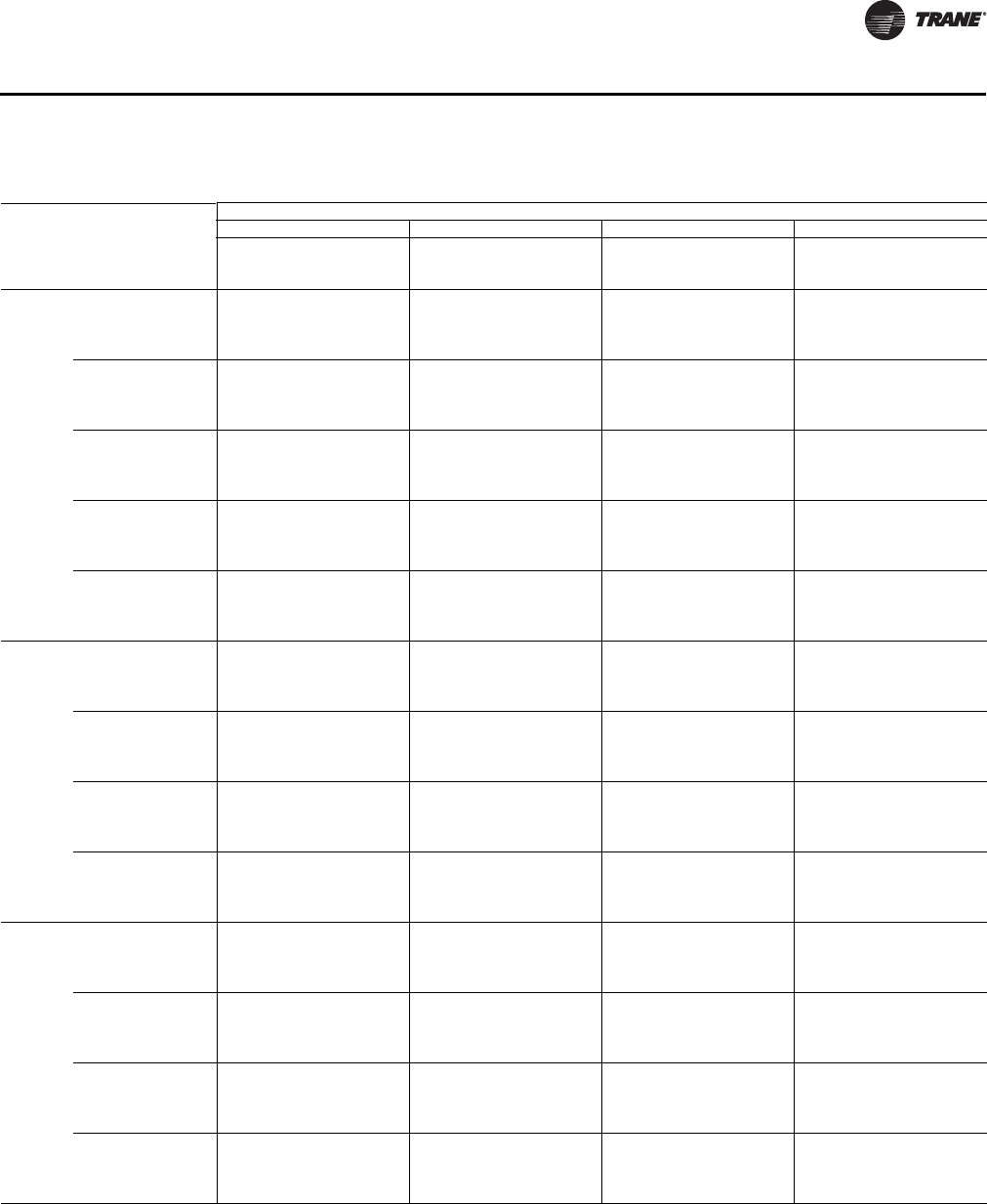
UV-PRC003-EN 47
Performance Data
Table 27. VUV 125, cooling coil E, 3-row / 16 fpi
Entering
Wet Bulb
Temp
(°F)
Entering
Dry Bulb
Temp
(°F)
Entering
Water
Temp
(°F)
Flow Rate (gpm)
6 8 10 14
Total
Capacity
(MBh)
Sensible
Capacity
(MBh)
ΔT
(°F)
Total
Capacity
(MBh)
Sensible
Capacity
(MBh)
ΔT
(°F)
Total
Capacity
(MBh)
Sensible
Capacity
(MBh)
ΔT
(°F)
Total
Capacity
(MBh)
Sensible
Capacity
(MBh)
ΔT
(°F)
61 70 40 28.5 19.6 9.9 32.7 21.3 8.4 35.5 22.4 7.3 39.0 23.9 5.7
42 27.0 19.1 9.4 30.9 20.6 8.0 33.5 21.6 6.9 36.8 23.0 5.4
45 24.8 18.3 8.6 28.2 19.5 7.3 30.5 20.4 6.3 33.4 21.5 4.9
48 22.4 17.4 7.8 25.4 18.4 6.6 27.4 19.2 5.7 29.9 20.1 4.4
75 40 31.1 25.5 10.7 35.6 27.6 9.2 38.7 29.1 8.0 42.6 31.0 6.2
42 29.5 24.7 10.2 33.7 26.7 8.7 36.5 28.0 7.5 40.1 29.8 5.9
45 27.0 23.6 9.4 30.7 25.3 8.0 33.2 26.4 6.9 36.4 27.9 5.4
48 24.5 22.5 8.5 27.7 23.9 7.2 29.8 24.8 6.2 32.6 26.1 4.8
80 40 34.5 30.8 11.9 39.5 33.4 10.2 42.9 35.2 8.8 47.2 37.5 6.9
42 32.7 29.9 11.3 37.4 32.3 9.6 40.5 33.9 8.3 44.5 36.0 6.5
45 30.0 28.6 10.4 34.1 30.6 8.8 36.9 32.0 7.6 40.4 33.8 5.9
48 27.1 27.1 9.4 30.7 28.9 7.9 33.1 30.1 6.8 36.1 31.6 5.3
85 40 38.5 35.9 13.2 44.1 38.8 11.3 47.9 40.9 9.8 52.7 43.7 7.7
42 36.5 34.8 12.5 41.7 37.5 10.7 45.2 39.4 9.3 49.7 41.9 7.3
45 33.4 33.3 11.5 38.0 35.6 9.8 41.1 37.2 8.4 45.0 39.3 6.6
48 30.3 30.3 10.5 34.2 33.6 8.8 36.9 35.0 7.6 40.3 36.7 5.9
90 40 42.9 40.6 14.7 49.2 44.0 12.6 53.4 46.4 10.9 58.7 49.5 8.5
42 40.7 39.5 13.9 46.5 42.5 11.9 50.4 44.7 10.3 55.3 47.5 8.1
45 37.3 37.3 12.8 42.4 40.3 10.9 45.8 42.2 9.4 50.2 44.5 7.3
48 33.7 33.7 11.6 38.2 38.1 9.8 41.2 39.6 8.5 45.0 41.6 6.6
67 75 40 38.9 21.1 13.3 44.6 22.9 11.4 48.4 24.1 9.9 53.2 25.8 7.8
42 36.9 20.5 12.7 42.1 22.1 10.8 45.7 23.3 9.4 50.2 24.7 7.3
45 33.8 19.6 11.6 38.4 21.0 9.9 41.6 22.0 8.5 45.5 23.2 6.7
48 30.6 18.7 10.6 34.6 19.8 8.9 37.3 20.6 7.7 40.8 21.7 6.0
80 40 40.8 27.4 14.0 46.8 29.7 12.0 50.8 31.3 10.4 55.9 33.3 8.1
42 38.7 26.6 13.3 44.2 28.7 11.3 48.0 30.1 9.8 52.7 32.0 7.7
45 35.5 25.4 12.2 40.3 27.2 10.4 43.6 28.4 8.9 47.8 30.0 7.0
48 32.1 24.2 11.1 36.3 25.7 9.4 39.2 26.7 8.1 42.8 28.0 6.3
85 40 43.5 33.4 14.9 49.8 36.2 12.7 54.1 38.2 11.0 59.5 40.7 8.7
42 41.2 32.5 14.1 47.1 35.0 12.0 51.1 36.8 10.4 56.1 39.1 8.2
45 37.8 31.0 13.0 42.9 33.2 11.0 46.4 34.7 9.5 50.9 36.6 7.4
48 34.2 29.5 11.8 38.7 31.3 9.9 41.7 32.6 8.6 45.5 34.2 6.7
90 40 46.7 39.3 15.9 53.4 42.5 13.6 58.0 44.8 11.8 63.8 47.8 9.3
42 44.2 38.2 15.1 50.5 41.1 12.9 54.8 43.2 11.2 60.1 45.9 8.8
45 40.5 36.5 13.9 46.1 39.0 11.8 49.8 40.8 10.2 54.6 43.1 8.0
48 36.7 34.7 12.6 41.5 36.8 10.6 44.7 38.3 9.2 48.8 40.2 7.1
70 75 40 44.3 18.5 15.1 50.7 20.1 13.0 55.1 21.1 11.2 60.6 22.5 8.8
42 42.0 18.0 14.4 48.0 19.4 12.3 52.0 20.4 10.6 57.1 21.6 8.3
45 38.5 17.2 13.2 43.7 18.4 11.2 47.3 19.2 9.7 51.8 20.3 7.6
48 34.8 16.4 12.0 39.4 17.4 10.1 42.5 18.1 8.7 46.4 19.0 6.8
80 40 45.5 24.9 15.5 52.1 26.9 13.3 56.6 28.4 11.5 62.3 30.3 9.1
42 43.1 24.2 14.8 49.3 26.0 12.6 53.4 27.3 10.9 58.7 29.1 8.5
45 39.5 23.1 13.5 44.9 24.7 11.5 48.6 25.8 9.9 53.2 27.3 7.8
48 35.8 22.0 12.3 40.5 23.3 10.4 43.6 24.2 8.9 47.7 25.5 7.0
85 40 47.5 31.1 16.2 54.4 33.7 13.9 59.1 35.6 12.0 65.0 37.9 9.4
42 45.0 30.3 15.4 51.4 32.6 13.1 55.8 34.3 11.4 61.2 36.4 8.9
45 41.2 28.9 14.1 46.9 30.9 12.0 50.7 32.3 10.4 55.5 34.1 8.1
48 37.3 27.5 12.8 42.2 29.2 10.8 45.5 30.4 9.3 49.7 31.9 7.3
90 40 50.1 37.3 17.1 57.3 40.4 14.6 62.3 42.6 12.7 68.5 45.4 9.9
42 47.5 36.2 16.2 54.2 39.0 13.8 58.8 41.0 12.0 64.5 43.6 9.4
45 43.5 34.6 14.9 49.4 37.0 12.6 53.5 38.7 10.9 58.5 40.9 8.5
48 39.4 33.0 13.5 44.5 35.0 11.4 48.0 36.4 9.8 52.4 38.2 7.6
Cooling - 125 - Coil E
UV-PRC003-EN.book Page 47 Tuesday, June 4, 2013 8:59 PM

48 UV-PRC003-EN
Performance Data
Table 28. VUV 125, cooling coil F, 4-row / 12 fpi
Entering
Wet Bulb
Temp
(°F)
Entering
Dry Bulb
Temp
(°F)
Entering
Water
Temp
(°F)
Flow Rate (gpm)
6 8 10 14
Total
Capacity
(MBh)
Sensible
Capacity
(MBh)
ΔT
(°F)
Total
Capacity
(MBh)
Sensible
Capacity
(MBh)
ΔT
(°F)
Total
Capacity
(MBh)
Sensible
Capacity
(MBh)
ΔT
(°F)
Total
Capacity
(MBh)
Sensible
Capacity
(MBh)
ΔT
(°F)
61 70 40 26.4 19.5 9.2 31.3 21.4 8.1 34.9 22.9 7.2 39.7 25.1 5.8
42 24.9 18.9 8.7 29.4 20.7 7.6 32.8 22.1 6.8 37.4 24.1 5.5
45 22.6 18.0 7.9 26.6 19.6 6.9 29.7 20.8 6.2 33.8 22.5 5.0
48 20.3 17.0 7.1 23.8 18.5 6.2 26.4 19.6 5.5 30.1 20.9 4.5
75 40 28.7 25.2 10.0 34.1 27.7 8.8 38.1 29.7 7.8 43.3 32.6 6.4
42 27.1 24.4 9.4 32.1 26.8 8.3 35.8 28.6 7.4 40.8 31.2 6.0
45 24.6 23.3 8.6 29.0 25.4 7.5 32.4 27.0 6.7 36.8 29.1 5.4
48 22.1 22.1 7.7 25.9 24.0 6.8 28.8 25.3 6.0 32.8 27.1 4.8
80 40 31.9 30.5 11.0 37.8 33.6 9.7 42.2 35.9 8.7 48.1 39.4 7.0
42 30.1 29.6 10.4 35.6 32.4 9.2 39.7 34.6 8.2 45.2 37.8 6.6
45 27.3 27.3 9.5 32.2 30.8 8.3 35.9 32.7 7.4 40.8 35.3 6.0
48 24.5 24.5 8.5 28.7 28.7 7.5 32.0 30.7 6.6 36.4 32.8 5.4
85 40 35.6 35.5 12.2 42.2 39.0 10.8 47.1 41.8 9.6 53.6 45.9 7.8
42 33.6 33.6 11.6 39.7 37.7 10.2 44.3 40.3 9.1 50.4 43.9 7.4
45 30.5 30.5 10.5 35.9 35.8 9.3 40.0 38.0 8.2 45.6 41.0 6.7
48 27.3 27.3 9.5 32.1 32.1 8.3 35.7 35.7 7.4 40.6 38.2 6.0
90 40 39.7 39.7 13.6 47.0 44.2 12.0 52.5 47.4 10.7 59.8 52.0 8.7
42 37.4 37.4 12.8 44.3 42.7 11.3 49.4 45.6 10.1 56.2 49.8 8.2
45 34.0 34.0 11.7 40.1 40.1 10.3 44.6 43.0 9.1 50.8 46.5 7.4
48 30.5 30.5 10.5 35.7 35.7 9.2 39.8 39.8 8.2 45.3 43.2 6.6
67 75 40 36.0 20.9 12.4 42.7 23.0 10.9 47.6 24.7 9.7 54.2 27.1 7.9
42 33.9 20.3 11.7 40.2 22.3 10.3 44.8 23.8 9.2 51.0 25.9 7.4
45 30.8 19.3 10.6 36.3 21.1 9.4 40.5 22.4 8.3 46.1 24.2 6.7
48 27.6 18.3 9.6 32.4 19.9 8.4 36.1 21.1 7.4 41.0 22.5 6.0
80 40 37.7 27.1 12.9 44.8 29.8 11.5 50.0 31.9 10.2 56.9 35.0 8.3
42 35.6 26.3 12.2 42.1 28.8 10.8 47.0 30.7 9.6 53.5 33.5 7.8
45 32.3 25.0 11.2 38.1 27.3 9.8 42.5 29.0 8.7 48.3 31.3 7.1
48 29.0 23.7 10.0 34.0 25.8 8.8 37.8 27.3 7.8 43.0 29.1 6.3
85 40 40.2 33.1 13.8 47.7 36.4 12.2 53.2 39.0 10.9 60.6 42.8 8.8
42 37.9 32.1 13.0 44.9 35.2 11.5 50.0 37.5 10.2 57.0 40.9 8.3
45 34.4 30.5 11.8 40.6 33.3 10.4 45.2 35.4 9.3 51.5 38.2 7.5
48 30.9 29.0 10.7 36.2 31.5 9.3 40.3 33.3 8.3 45.8 35.6 6.7
90 40 43.1 38.9 14.7 51.1 42.7 13.1 57.1 45.8 11.6 65.0 50.3 9.4
42 40.7 37.7 13.9 48.1 41.3 12.3 53.7 44.1 11.0 61.1 48.1 8.9
45 36.9 35.9 12.7 43.5 39.2 11.2 48.5 41.6 9.9 55.2 44.9 8.0
48 33.1 33.1 11.4 38.8 37.0 10.0 43.2 39.1 8.9 49.2 41.8 7.2
70 75 40 40.9 18.3 14.0 48.6 20.1 12.4 54.2 21.6 11.1 61.7 23.7 9.0
42 38.6 17.8 13.2 45.7 19.5 11.7 51.0 20.8 10.4 58.0 22.7 8.4
45 35.1 16.9 12.1 41.4 18.5 10.6 46.1 19.6 9.4 52.4 21.2 7.6
48 31.5 16.0 10.9 36.9 17.4 9.5 41.0 18.4 8.4 46.7 19.7 6.8
80 40 42.0 24.6 14.4 49.9 27.1 12.7 55.7 29.0 11.4 63.4 31.8 9.2
42 39.7 23.9 13.6 46.9 26.2 12.0 52.4 27.9 10.7 59.6 30.5 8.7
45 36.0 22.7 12.4 42.5 24.8 10.9 47.3 26.3 9.7 53.9 28.4 7.9
48 32.3 21.5 11.1 37.9 23.4 9.8 42.2 24.8 8.7 48.0 26.5 7.0
85 40 43.9 30.8 15.0 52.0 33.9 13.3 58.1 36.3 11.8 66.2 39.9 9.6
42 41.4 29.9 14.2 49.0 32.8 12.5 54.6 35.0 11.2 62.2 38.1 9.0
45 37.6 28.5 12.9 44.3 31.1 11.4 49.4 33.0 10.1 56.2 35.6 8.2
48 33.7 27.0 11.6 39.5 29.3 10.2 44.0 31.0 9.0 50.1 33.1 7.3
90 40 46.3 36.9 15.8 54.9 40.6 14.0 61.2 43.5 12.5 69.7 47.7 10.1
42 43.6 35.8 14.9 51.6 39.2 13.2 57.6 41.9 11.7 65.6 45.7 9.5
45 39.6 34.1 13.6 46.7 37.2 12.0 52.1 39.5 10.6 59.2 42.7 8.6
48 35.5 32.3 12.2 41.7 35.1 10.7 46.4 37.1 9.5 52.8 39.7 7.7
Cooling - 125 - Coil F
UV-PRC003-EN.book Page 48 Tuesday, June 4, 2013 8:59 PM

UV-PRC003-EN 49
Performance Data
Table 29. VUV 125, cooling coil G, 4-row / 16 fpi
Entering
Wet Bulb
Temp
(°F)
Entering
Dry Bulb
Temp
(°F)
Entering
Water
Temp
(°F)
Flow Rate (gpm)
6 8 10 14
Total
Capacity
(MBh)
Sensible
Capacity
(MBh)
ΔT
(°F)
Total
Capacity
(MBh)
Sensible
Capacity
(MBh)
ΔT
(°F)
Total
Capacity
(MBh)
Sensible
Capacity
(MBh)
ΔT
(°F)
Total
Capacity
(MBh)
Sensible
Capacity
(MBh)
ΔT
(°F)
61 70 40 27.2 19.8 9.4 32.3 21.8 8.4 36.1 23.4 7.4 41.1 25.7 6.0
42 25.7 19.2 8.9 30.5 21.1 7.9 34.0 22.5 7.0 38.7 24.6 5.7
45 23.4 18.3 8.2 27.6 20.0 7.2 30.7 21.2 6.4 35.0 22.9 5.2
48 21.0 17.3 7.4 24.6 18.8 6.4 27.4 19.9 5.7 31.2 21.3 4.6
75 40 29.7 25.6 10.3 35.3 28.2 9.1 39.4 30.3 8.1 44.8 33.3 6.6
42 28.0 24.9 9.7 33.2 27.3 8.6 37.1 29.2 7.6 42.2 31.9 6.2
45 25.5 23.7 8.9 30.1 25.9 7.8 33.5 27.5 6.9 38.2 29.7 5.6
48 22.9 22.4 8.0 26.9 24.4 7.0 29.9 25.8 6.2 34.0 27.6 5.0
80 40 32.9 31.0 11.4 39.1 34.2 10.1 43.7 36.7 9.0 49.7 40.3 7.3
42 31.1 30.1 10.7 36.8 33.0 9.5 41.1 35.3 8.4 46.8 38.6 6.8
45 28.3 28.3 9.8 33.4 31.3 8.6 37.2 33.3 7.7 42.3 36.0 6.2
48 25.4 25.4 8.8 29.8 29.6 7.7 33.2 31.2 6.9 37.7 33.4 5.5
85 40 36.8 36.1 12.6 43.7 39.8 11.2 48.7 42.7 10.0 55.5 46.9 8.1
42 34.7 34.7 11.9 41.1 38.4 10.6 45.9 41.1 9.4 52.2 44.9 7.6
45 31.6 31.6 10.9 37.2 36.4 9.6 41.5 38.7 8.5 47.2 41.8 6.9
48 28.3 28.3 9.8 33.3 33.3 8.6 37.0 36.3 7.6 42.1 38.9 6.2
90 40 41.0 40.9 14.0 48.7 45.1 12.4 54.3 48.3 11.1 61.9 53.2 9.0
42 38.7 38.7 13.3 45.8 43.5 11.7 51.1 46.5 10.4 58.2 50.8 8.5
45 35.2 35.2 12.1 41.5 41.3 10.7 46.3 43.9 9.5 52.6 47.4 7.7
48 31.6 31.6 10.9 37.1 37.1 9.5 41.2 41.2 8.5 46.9 44.0 6.9
67 75 40 37.2 21.3 12.8 44.1 23.5 11.3 49.3 25.2 10.1 56.1 27.7 8.2
42 35.1 20.7 12.1 41.6 22.7 10.7 46.4 24.2 9.5 52.8 26.5 7.7
45 31.9 19.7 11.0 37.6 21.5 9.7 41.9 22.8 8.6 47.7 24.7 7.0
48 28.6 18.6 9.9 33.6 20.3 8.7 37.4 21.4 7.7 42.5 22.9 6.2
80 40 39.0 27.6 13.4 46.3 30.4 11.9 51.7 32.6 10.6 58.9 35.8 8.6
42 36.8 26.7 12.6 43.6 29.3 11.2 48.6 31.4 10.0 55.4 34.2 8.1
45 33.5 25.5 11.5 39.5 27.8 10.2 44.0 29.5 9.0 50.1 31.9 7.3
48 30.0 24.1 10.4 35.3 26.2 9.1 39.2 27.7 8.1 44.6 29.7 6.5
85 40 41.5 33.7 14.2 49.3 37.1 12.6 55.0 39.8 11.2 62.7 43.7 9.1
42 39.2 32.6 13.4 46.4 35.8 11.9 51.8 38.3 10.6 59.0 41.8 8.6
45 35.6 31.1 12.2 42.0 33.9 10.8 46.8 36.1 9.6 53.3 39.0 7.8
48 32.0 29.5 11.0 37.5 32.0 9.7 41.8 33.9 8.6 47.5 36.2 6.9
90 40 44.5 39.5 15.2 52.9 43.6 13.5 59.0 46.7 12.0 67.2 51.4 9.8
42 42.0 38.4 14.4 49.8 42.1 12.7 55.6 45.0 11.3 63.3 49.1 9.2
45 38.2 36.5 13.1 45.1 39.9 11.6 50.3 42.4 10.3 57.2 45.8 8.3
48 34.3 34.3 11.8 40.3 37.6 10.3 44.8 39.8 9.2 51.0 42.6 7.4
70 75 40 42.3 18.6 14.5 50.2 20.5 12.8 56.1 22.0 11.4 63.8 24.2 9.3
42 39.9 18.1 13.7 47.3 19.8 12.1 52.8 21.2 10.8 60.1 23.2 8.7
45 36.3 17.2 12.5 42.8 18.8 11.0 47.7 20.0 9.8 54.3 21.6 7.9
48 32.6 16.3 11.2 38.3 17.7 9.8 42.6 18.8 8.7 48.4 20.1 7.1
80 40 43.4 25.0 14.9 51.6 27.6 13.2 57.6 29.6 11.7 65.6 32.5 9.5
42 41.0 24.3 14.0 48.6 26.7 12.4 54.2 28.5 11.1 61.7 31.1 9.0
45 37.3 23.1 12.8 44.0 25.3 11.3 49.0 26.8 10.0 55.8 29.0 8.1
48 33.5 21.9 11.5 39.3 23.8 10.1 43.7 25.2 9.0 49.7 26.9 7.3
85 40 45.3 31.4 15.5 53.8 34.5 13.7 60.1 37.0 12.2 68.4 40.7 9.9
42 42.8 30.4 14.6 50.7 33.4 13.0 56.6 35.7 11.5 64.4 39.0 9.4
45 38.9 29.0 13.3 45.9 31.6 11.8 51.2 33.6 10.5 58.2 36.3 8.5
48 34.9 27.4 12.0 41.0 29.9 10.5 45.6 31.6 9.3 51.9 33.7 7.6
90 40 47.8 37.6 16.3 56.7 41.4 14.5 63.3 44.4 12.9 72.1 48.8 10.5
42 45.1 36.4 15.4 53.5 40.0 13.6 59.6 42.7 12.1 67.9 46.7 9.9
45 41.0 34.7 14.0 48.4 37.9 12.4 53.9 40.3 11.0 61.4 43.5 8.9
48 36.8 32.9 12.6 43.2 35.8 11.1 48.1 37.8 9.8 54.7 40.4 8.0
Cooling - 125 - Coil G
UV-PRC003-EN.book Page 49 Tuesday, June 4, 2013 8:59 PM

50 UV-PRC003-EN
Performance Data
Table 30. VUV 125, cooling coil H, 3-row / 16 fpi
Entering
Wet Bulb
Temp
(°F)
Entering
Dry Bulb
Temp
(°F)
Entering
Water
Temp
(°F)
Flow Rate (gpm)
6 8 10 14
Total
Capacity
(MBh)
Sensible
Capacity
(MBh)
ΔT
(°F)
Total
Capacity
(MBh)
Sensible
Capacity
(MBh)
ΔT
(°F)
Total
Capacity
(MBh)
Sensible
Capacity
(MBh)
ΔT
(°F)
Total
Capacity
(MBh)
Sensible
Capacity
(MBh)
ΔT
(°F)
61 70 40 30.5 21.0 10.5 34.7 22.8 9.0 37.6 24.0 7.7 41.2 25.6 6.0
42 28.7 20.2 9.9 32.6 21.8 8.4 35.2 23.0 7.3 38.6 24.4 5.7
45 26.0 19.1 9.0 29.3 20.5 7.6 31.6 21.4 6.5 34.6 22.7 5.1
48 23.2 17.9 8.1 26.0 19.1 6.8 27.9 19.9 5.8 30.5 20.9 4.5
75 40 33.3 27.2 11.5 37.9 29.5 9.7 41.0 31.1 8.4 45.0 33.2 6.6
42 31.3 26.2 10.8 35.5 28.3 9.2 38.4 29.8 7.9 42.1 31.6 6.2
45 28.3 24.7 9.8 32.0 26.5 8.3 34.5 27.8 7.1 37.7 29.4 5.5
48 25.2 23.2 8.8 28.3 24.7 7.4 30.5 25.8 6.3 33.2 27.1 4.9
80 40 36.9 32.9 12.7 42.0 35.7 10.8 45.5 37.7 9.3 49.9 40.2 7.3
42 34.7 31.7 12.0 39.4 34.3 10.1 42.6 36.0 8.7 46.7 38.3 6.8
45 31.4 29.9 10.8 35.5 32.1 9.1 38.2 33.6 7.9 41.8 35.5 6.1
48 28.0 28.0 9.7 31.4 29.9 8.1 33.8 31.2 7.0 36.9 32.8 5.4
85 40 41.2 38.3 14.1 46.9 41.6 12.0 50.7 43.8 10.4 55.6 46.7 8.1
42 38.8 36.9 13.3 44.0 39.9 11.3 47.5 41.9 9.7 52.1 44.5 7.6
45 35.1 34.8 12.1 39.6 37.3 10.2 42.7 39.1 8.8 46.6 41.3 6.8
48 31.3 31.3 10.8 35.1 34.8 9.0 37.7 36.3 7.8 41.1 38.2 6.0
90 40 45.9 43.4 15.7 52.2 47.1 13.3 56.6 49.7 11.5 62.0 52.9 9.0
42 43.2 41.8 14.8 49.0 45.2 12.5 53.0 47.5 10.8 58.0 50.5 8.5
45 39.1 39.1 13.4 44.1 42.3 11.3 47.6 44.3 9.7 52.0 46.8 7.6
48 34.8 34.8 12.0 39.1 39.1 10.0 42.0 41.1 8.6 45.8 43.3 6.7
67 75 40 41.7 22.6 14.3 47.4 24.5 12.1 51.3 25.8 10.5 56.2 27.6 8.2
42 39.2 21.8 13.4 44.4 23.5 11.4 48.1 24.7 9.8 52.6 26.3 7.7
45 35.4 20.5 12.2 40.0 22.0 10.3 43.1 23.1 8.8 47.1 24.4 6.9
48 31.6 19.3 10.9 35.4 20.5 9.1 38.1 21.4 7.8 41.6 22.5 6.1
80 40 43.7 29.2 14.9 49.7 31.7 12.7 53.8 33.5 11.0 59.0 35.7 8.6
42 41.1 28.2 14.1 46.6 30.4 11.9 50.4 32.0 10.3 55.2 34.0 8.0
45 37.2 26.6 12.8 42.0 28.5 10.8 45.3 29.8 9.3 49.5 31.6 7.2
48 33.1 25.0 11.4 37.2 26.6 9.6 40.0 27.7 8.2 43.6 29.2 6.4
85 40 46.5 35.7 15.9 52.9 38.7 13.5 57.3 40.8 11.7 62.8 43.5 9.1
42 43.8 34.4 15.0 49.6 37.1 12.7 53.7 39.1 11.0 58.8 41.5 8.6
45 39.6 32.4 13.6 44.7 34.8 11.4 48.2 36.4 9.9 52.7 38.5 7.7
48 35.3 30.5 12.1 39.6 32.5 10.2 42.6 33.8 8.7 46.4 35.6 6.8
90 40 49.9 41.9 17.0 56.8 45.5 14.5 61.5 48.0 12.5 67.4 51.2 9.8
42 47.0 40.4 16.0 53.3 43.6 13.6 57.6 45.9 11.7 63.1 48.8 9.2
45 42.5 38.1 14.5 47.9 40.9 12.3 51.7 42.8 10.6 56.5 45.3 8.2
48 37.9 35.8 13.0 42.5 38.1 10.9 45.7 39.8 9.4 49.8 41.8 7.3
70 75 40 47.4 19.8 16.2 53.9 21.5 13.8 58.4 22.6 11.9 64.0 24.1 9.3
42 44.6 19.0 15.2 50.6 20.6 12.9 54.7 21.6 11.2 59.9 23.0 8.7
45 40.3 18.0 13.8 45.5 19.3 11.7 49.1 20.2 10.0 53.7 21.3 7.8
48 36.0 16.9 12.4 40.3 18.0 10.4 43.4 18.7 8.9 47.3 19.7 6.9
80 40 48.7 26.5 16.6 55.4 28.8 14.1 60.0 30.4 12.2 65.8 32.4 9.6
42 45.8 25.6 15.6 52.0 27.6 13.3 56.2 29.1 11.5 61.5 30.9 8.9
45 41.4 24.1 14.2 46.8 25.9 12.0 50.4 27.1 10.3 55.1 28.7 8.0
48 36.9 22.7 12.7 41.4 24.2 10.6 44.6 25.2 9.1 48.6 26.5 7.1
85 40 50.8 33.2 17.3 57.8 36.1 14.7 62.6 38.1 12.7 68.6 40.6 10.0
42 47.8 32.0 16.3 54.2 34.6 13.8 58.6 36.4 11.9 64.2 38.7 9.3
45 43.2 30.2 14.8 48.8 32.4 12.5 52.6 33.9 10.7 57.5 35.9 8.4
48 38.5 28.4 13.2 43.2 30.2 11.1 46.5 31.5 9.5 50.7 33.2 7.4
90 40 53.6 39.8 18.2 60.9 43.2 15.5 66.0 45.6 13.4 72.3 48.6 10.5
42 50.4 38.4 17.2 57.2 41.5 14.6 61.8 43.6 12.6 67.7 46.3 9.8
45 45.6 36.2 15.6 51.4 38.8 13.1 55.5 40.7 11.3 60.6 43.0 8.8
48 40.6 34.0 13.9 45.6 36.2 11.7 49.0 37.8 10.0 53.5 39.7 7.8
Cooling - 125 - Coil H
UV-PRC003-EN.book Page 50 Tuesday, June 4, 2013 8:59 PM
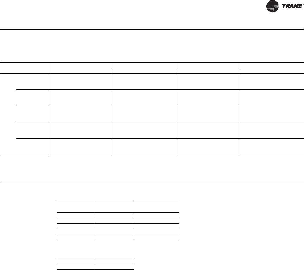
UV-PRC003-EN 51
Performance Data
Table 31. VUV 125, cooling coil J (DX)
Size EWB
Suct
Temp
EDB = 70°F EDB = 75°F EDB = 80°F EDB = 85°F
TC SC LDB LWB TC SC LDB LWB TC SC LDB LWB TC SC LDB LWB
1250 61 40 35.1 23.4 52.7 51.0 38.4 30.9 52.2 49.9 42.5 37.8 52.1 48.5 47.5 44.3 52.3 46.8
45 29.4 21.2 54.3 52.8 32.2 28.1 54.2 51.9 35.6 34.4 54.6 50.8 39.8 39.8 55.6 49.4
50 23.7 19.1 55.9 54.5 25.9 25.3 56.3 53.8 28.7 28.7 58.8 52.9 32.1 32.1 61.3 51.8
64 40 41.7 20.2 55.1 52.8 43.9 28.4 54.0 52.0 46.7 36.1 53.3 51.1 50.2 43.4 52.9 49.9
45 34.9 18.3 56.5 54.8 36.8 25.8 55.9 54.2 39.1 32.8 55.8 53.4 42.1 39.4 55.9 52.5
50 28.2 16.5 57.8 56.7 29.7 23.2 57.9 56.2 31.6 29.5 58.2 55.6 34.0 34.0 59.9 54.9
67 40 49.3 16.2 58.0 54.4 50.9 24.9 56.6 53.9 52.8 33.1 55.5 53.3 55.1 41.0 54.7 52.5
45 41.3 14.7 59.1 56.7 42.7 22.6 58.3 56.2 44.2 30.1 57.8 55.8 46.2 37.2 57.5 55.1
50 33.3 13.2 60.2 58.9 34.4 20.3 60.0 58.5 35.7 27.1 60.0 58.1 37.3 33.5 60.2 57.6
70 40 59.0 20.5 59.9 55.6 60.3 29.1 58.5 55.2 61.9 37.4 57.4 54.6
45 49.4 18.6 61.3 58.3 50.5 26.4 60.5 57.9 51.9 34.0 59.9 57.5
50 39.9 16.8 62.6 60.8 40.8 23.8 62.4 60.5 41.9 30.6 62.4 60.1
73 40 68.9 24.3 62.0 57.0 70.1 32.8 60.8 56.6
45 57.8 22.1 63.7 60.0 58.7 29.8 63.0 59.7
50 46.6 19.9 65.3 62.8 47.4 26.9 65.1 62.5
EDB = Entering Air Temperature, Dry Bulb (°F)
EWB = Entering Air Temperature, Wet Bulb (°F)
TC = Total Capacity (MBh)
SC = Sensible Capacity (MBh)
LDB = Leaving Air Temperature, Dry Bulb (°F)
LWB = Leaving Air Temperature, Wet Bulb (°F)
Table 32. Airflow correction (% of design airflow)
%
Total Capacity
(MBh)
Sensible Capacity
(MBh)
120 1.025 1.105
110 1.012 1.051
100 1.000 0.998
90 0.987 0.945
80 0.974 0.892
Table 33. Airflow through coil J
Unit Model 1250
Rated CFM 1253
Cooling - 125 - Coil (DX)
UV-PRC003-EN.book Page 51 Tuesday, June 4, 2013 8:59 PM
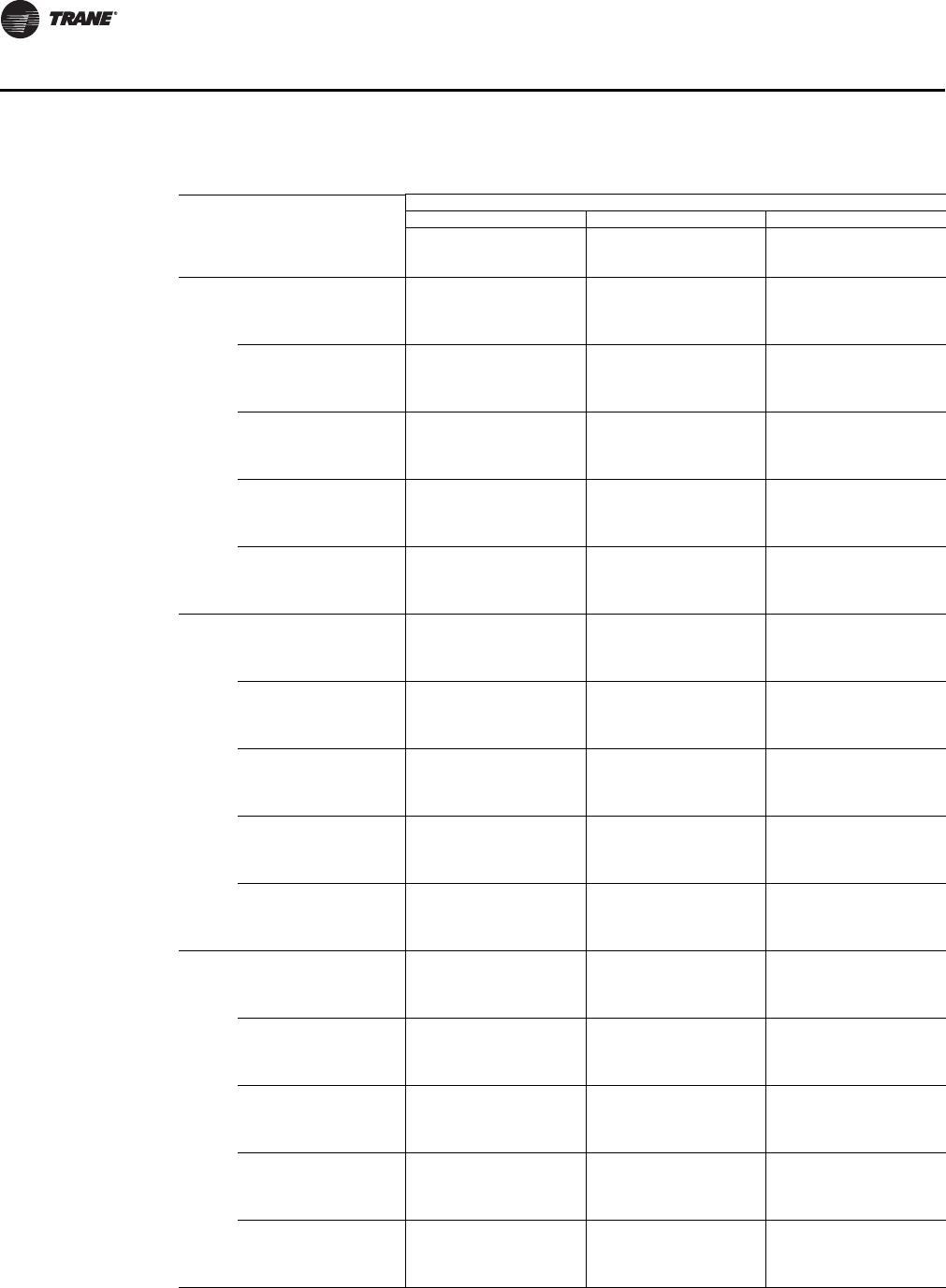
52 UV-PRC003-EN
Performance Data
Table 34. VUV 125, hydronic heating coils A (1-row / 12 fpi), B (2-row / 12 fpi), C (2-row/ 16 fpi)
Coil
Entering
Air Temp,
Dry Bulb
(°F)
Entering
Water
Temp (°F)
Flow Rate (gpm)
246
Total
Capacity
(MBh)
Waterside
Temp Drop
(°F)
Total
Capacity
(MBh)
Waterside
Temp Drop
(°F)
Total
Capacity
(MBh)
Waterside
Temp Drop
(°F)
A50 120 29.4 28.3 36.3 17.6 39.4 12.8
140 41.1 40.0 50.8 24.8 55.1 18.0
160 52.8 51.7 65.3 32.1 70.9 23.3
180 64.7 63.6 80.0 39.4 86.7 28.5
55 120 27.8 26.7 34.3 16.6 37.2 12.0
140 38.8 37.7 48.0 23.4 52.1 17.0
160 50.0 48.9 61.8 30.3 67.0 22.0
180 61.2 60.1 75.7 37.3 82.0 27.0
60 120 26.2 25.1 32.4 15.6 35.1 11.3
140 36.6 35.5 45.3 22.1 49.1 16.0
160 47.2 46.1 58.3 28.6 63.2 20.7
180 57.7 56.6 71.4 35.1 77.4 25.4
65 120 24.6 23.5 30.4 14.6 33.0 10.6
140 34.4 33.3 42.6 20.7 46.2 15.0
160 44.3 43.2 54.8 26.8 59.4 19.4
180 54.3 53.2 67.1 33.0 72.7 23.9
70 120 23.1 22.0 28.5 13.7 30.9 9.9
140 32.2 31.1 39.9 19.4 43.2 14.0
160 41.5 40.4 51.3 25.1 55.6 18.2
180 50.8 49.7 62.8 30.8 68.1 22.3
B50 120 34.8 33.7 46.1 22.5 51.1 16.7
140 49.2 48.1 64.8 31.8 71.8 23.6
160 63.4 62.3 83.5 41.2 92.5 30.5
180 77.6 76.5 102.2 50.5 113.3 37.4
55 120 33.0 31.9 43.6 21.2 48.4 15.8
140 46.5 45.4 61.3 30.1 67.9 22.3
160 60.0 58.9 79.0 38.9 87.5 28.8
180 73.4 72.3 96.7 47.8 107.2 35.4
60 120 31.1 30.0 41.1 20.0 45.6 14.8
140 43.9 42.8 57.8 28.3 64.0 21.0
160 56.6 55.5 74.5 36.7 82.5 27.1
180 69.2 68.1 91.2 45.0 101.1 33.3
65 120 29.2 28.1 38.7 18.8 42.9 13.9
140 41.3 40.2 54.3 26.6 60.2 19.7
160 53.2 52.1 70.0 34.4 77.6 25.5
180 65.1 64.0 85.8 42.3 95.0 31.3
70 120 27.4 26.3 36.2 17.5 40.1 13.0
140 38.6 37.5 50.8 24.8 56.3 18.4
160 49.8 48.7 65.6 32.2 72.6 23.8
180 60.9 59.8 80.3 39.6 88.9 29.3
C50 120 36.9 35.8 50.3 24.6 56.3 18.4
140 52.1 51.0 70.7 34.8 79.1 26.0
160 67.2 66.1 91.1 45.0 102.0 33.6
180 82.2 81.1 111.6 55.2 124.9 41.3
55 120 34.9 33.8 47.6 23.2 53.3 17.4
140 49.2 48.1 66.9 32.9 74.8 24.6
160 63.6 62.5 86.2 42.5 96.5 31.8
180 77.7 76.6 105.6 52.2 118.2 39.0
60 120 32.9 31.8 44.9 21.9 50.2 16.4
140 46.5 45.4 63.1 31.0 70.6 23.2
160 60.0 58.9 81.3 40.1 91.0 30.0
180 73.3 72.2 99.6 49.2 111.5 36.8
65 120 30.9 29.8 42.2 20.5 47.2 15.4
140 43.7 42.6 59.3 29.1 66.3 21.7
160 56.4 55.3 76.5 37.7 85.6 28.2
180 69.0 67.9 93.6 46.2 104.8 34.6
70 120 28.9 27.8 39.5 19.2 44.2 14.4
140 40.9 39.8 55.5 27.2 62.1 20.3
160 52.7 51.6 71.5 35.2 80.1 26.3
180 64.5 63.4 87.6 43.2 98.1 32.3
Heating - 125 - Coil A, B, C
UV-PRC003-EN.book Page 52 Tuesday, June 4, 2013 8:59 PM
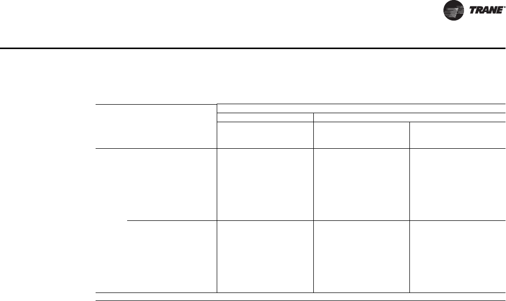
UV-PRC003-EN 53
Performance Data
Table 35. VUV 125, steam heating coils K (low-capacity), L (high-capacity)
Size Coil
Entering
Air Temp,
Dry Bulb
(°F)
Steam Pressure (psig)
51015
Total
Capacity
(MBh)
Airside
Temp Rise
(°F)
Total
Capacity
(MBh)
Airside
Temp Rise
(°F)
Total
Capacity
(MBh)
Airside
Temp Rise
(°F)
1250 K 0 116.9 86.6 123.0 91.1 128.1 94.9
10 111.8 82.7 117.8 87.2 122.9 91.1
20 106.6 79.0 112.7 83.5 117.8 87.3
30 101.6 75.2 107.6 79.7 112.8 83.6
40 96.5 71.5 102.5 76.0 107.7 79.8
50 91.3 67.6 97.4 72.1 102.5 76.0
60 86.1 63.7 92.1 68.2 97.3 72.1
70 81.0 60.0 87.0 64.5 92.2 68.3
L 0 138.1 102.3 145.3 107.6 151.4 112.1
10 132.1 97.8 139.2 103.1 145.3 107.6
20 126.0 93.3 133.1 98.6 139.2 103.1
30 119.9 88.8 127.0 94.1 133.2 98.6
40 113.8 84.3 121.0 89.6 127.1 94.1
50 107.7 79.8 114.9 85.1 121.0 89.7
60 101.7 75.3 108.8 80.6 115.0 85.2
70 95.6 70.8 102.8 76.1 108.9 80.7
psig = steam pressure (lb/in.2 gage)
Heating - 125 - Coil K, L
UV-PRC003-EN.book Page 53 Tuesday, June 4, 2013 8:59 PM

54 UV-PRC003-EN
Performance Data
Table 36. VUV 150, cooling coil D, 3-row / 12 fpi
Entering
Wet Bulb
Temp
(°F)
Entering
Dry Bulb
Temp
(°F)
Entering
Water
Temp
(°F)
Flow Rate (gpm)
6 8 10 14
Total
Capacity
(MBh)
Sensible
Capacity
(MBh)
ΔT
(°F)
Total
Capacity
(MBh)
Sensible
Capacity
(MBh)
ΔT
(°F)
Total
Capacity
(MBh)
Sensible
Capacity
(MBh)
ΔT
(°F)
Total
Capacity
(MBh)
Sensible
Capacity
(MBh)
ΔT
(°F)
61 70 40 30.9 23.0 10.7 36.5 25.3 9.4 41.0 27.0 8.4 46.9 29.3 6.9
42 29.2 22.2 10.1 34.5 24.4 8.9 38.5 26.0 7.9 43.9 28.1 6.4
45 26.6 21.1 9.3 31.3 23.1 8.1 34.9 24.5 7.2 39.4 26.3 5.8
48 24.1 19.9 8.4 28.1 21.7 7.3 31.2 23.0 6.5 34.9 24.5 5.2
75 40 33.7 29.8 11.6 39.9 32.7 10.3 44.7 34.9 9.2 51.1 38.0 7.5
42 31.8 28.8 11.0 37.6 31.6 9.7 42.0 33.6 8.6 47.9 36.4 7.0
45 29.0 27.3 10.1 34.1 29.9 8.8 38.0 31.7 7.8 43.0 34.0 6.3
48 26.2 25.8 9.1 30.7 28.2 8.0 34.0 29.8 7.0 38.0 31.8 5.6
80 40 37.3 36.0 12.8 44.2 39.6 11.3 49.5 42.3 10.1 56.7 46.0 8.3
42 35.3 34.9 12.2 41.7 38.2 10.7 46.6 40.7 9.6 53.1 44.0 7.8
45 32.2 32.2 11.1 37.9 36.2 9.8 42.2 38.4 8.7 47.7 41.2 7.0
48 29.1 29.1 10.1 34.0 34.0 8.8 37.7 36.0 7.8 42.2 38.5 6.2
85 40 41.7 41.7 14.3 49.3 46.1 12.6 55.3 49.2 11.3 63.3 53.5 9.2
42 39.4 39.4 13.5 46.5 44.5 11.9 52.0 47.4 10.6 59.3 51.2 8.6
45 35.9 35.9 12.4 42.3 42.1 10.9 47.1 44.6 9.7 53.2 48.0 7.8
48 32.5 32.5 11.2 38.0 38.0 9.8 42.1 41.9 8.7 47.1 44.8 6.9
90 40 46.5 46.5 15.9 55.0 52.2 14.0 61.6 55.7 12.6 70.5 60.6 10.2
42 43.9 43.9 15.0 51.8 50.4 13.3 58.0 53.7 11.8 66.1 58.0 9.6
45 40.1 40.1 13.8 47.1 47.1 12.1 52.5 50.6 10.7 59.3 54.3 8.6
48 36.2 36.2 12.5 42.3 42.3 10.9 46.9 46.9 9.6 52.5 50.7 7.7
67 75 40 42.1 24.7 14.4 49.9 27.2 12.8 55.9 29.0 11.4 63.9 31.5 9.3
42 39.8 23.9 13.7 47.0 26.2 12.0 52.6 27.9 10.8 59.9 30.2 8.7
45 36.3 22.7 12.5 42.7 24.8 11.0 47.6 26.3 9.8 53.8 28.3 7.9
48 32.8 21.5 11.3 38.4 23.4 9.9 42.5 24.7 8.7 47.6 26.4 7.0
80 40 44.2 32.0 15.1 52.3 35.2 13.4 58.6 37.5 12.0 67.1 40.8 9.8
42 41.8 31.0 14.3 49.3 34.0 12.6 55.2 36.1 11.3 62.9 39.1 9.2
45 38.1 29.4 13.1 44.8 32.1 11.5 49.9 34.1 10.2 56.5 36.6 8.2
48 34.5 27.8 11.9 40.3 30.3 10.4 44.6 32.0 9.2 49.9 34.2 7.3
85 40 47.1 39.1 16.1 55.7 42.9 14.2 62.4 45.8 12.7 71.4 49.8 10.4
42 44.5 37.8 15.2 52.5 41.5 13.4 58.7 44.1 12.0 66.9 47.7 9.7
45 40.6 35.8 13.9 47.7 39.2 12.2 53.1 41.6 10.9 60.1 44.7 8.8
48 36.7 33.9 12.6 42.9 37.0 11.0 47.5 39.1 9.7 53.2 41.7 7.8
90 40 50.5 45.9 17.2 59.7 50.5 15.2 67.0 53.9 13.6 76.6 58.5 11.1
42 47.7 44.4 16.3 56.3 48.7 14.4 63.0 51.9 12.8 71.8 56.1 10.4
45 43.5 42.1 14.9 51.2 46.1 13.1 57.0 48.9 11.6 64.5 52.5 9.4
48 39.4 39.4 13.5 46.0 43.4 11.8 51.0 45.9 10.4 57.0 49.0 8.3
70 75 40 48.0 21.6 16.4 56.7 23.8 14.5 63.6 25.4 13.0 72.8 27.6 10.6
42 45.3 20.9 15.5 53.5 23.0 13.7 59.8 24.4 12.2 68.2 26.4 9.9
45 41.3 19.9 14.2 48.6 21.7 12.5 54.1 23.0 11.1 61.2 24.8 8.9
48 37.4 18.8 12.9 43.7 20.5 11.2 48.4 21.6 9.9 54.2 23.1 7.9
80 40 49.3 29.1 16.8 58.3 32.0 14.9 65.3 34.1 13.3 74.8 37.1 10.9
42 46.5 28.1 15.9 55.0 30.8 14.0 61.5 32.8 12.5 70.1 35.5 10.2
45 42.5 26.7 14.6 49.9 29.2 12.8 55.6 30.9 11.4 62.9 33.2 9.2
48 38.4 25.2 13.2 44.9 27.5 11.5 49.7 29.1 10.2 55.7 31.0 8.1
85 40 51.4 36.4 17.5 60.8 40.0 15.5 68.2 42.7 13.9 78.0 46.4 11.3
42 48.6 35.2 16.6 57.4 38.6 14.6 64.2 41.1 13.1 73.1 44.5 10.6
45 44.3 33.4 15.2 52.1 36.5 13.3 58.0 38.7 11.8 65.7 41.6 9.5
48 40.1 31.6 13.8 46.8 34.4 12.0 51.9 36.4 10.6 58.1 38.9 8.5
90 40 54.2 43.6 18.5 64.1 47.9 16.3 71.9 51.2 14.6 82.2 55.6 11.9
42 51.2 42.2 17.5 60.5 46.3 15.4 67.6 49.3 13.8 77.1 53.3 11.2
45 46.7 40.0 16.0 54.9 43.8 14.0 61.2 46.4 12.5 69.2 49.9 10.1
48 42.2 37.8 14.5 49.4 41.3 12.6 54.7 43.6 11.2 61.2 46.5 8.9
Cooling - 150 - Coil D
UV-PRC003-EN.book Page 54 Tuesday, June 4, 2013 8:59 PM

UV-PRC003-EN 55
Performance Data
Table 37. VUV 150, cooling coil E, 3-row / 16 fpi
Entering
Wet Bulb
Temp
(°F)
Entering
Dry Bulb
Temp
(°F)
Entering
Water
Temp
(°F)
Flow Rate (gpm)
6 8 10 14
Total
Capacity
(MBh)
Sensible
Capacity
(MBh)
ΔT
(°F)
Total
Capacity
(MBh)
Sensible
Capacity
(MBh)
ΔT
(°F)
Total
Capacity
(MBh)
Sensible
Capacity
(MBh)
ΔT
(°F)
Total
Capacity
(MBh)
Sensible
Capacity
(MBh)
ΔT
(°F)
61 70 40 31.8 23.1 11.0 37.7 25.4 9.7 42.2 27.2 8.7 48.2 29.5 7.1
42 30.1 22.4 10.4 35.5 24.6 9.2 39.7 26.1 8.2 45.2 28.3 6.6
45 27.4 21.2 9.5 32.3 23.2 8.4 36.0 24.6 7.4 40.6 26.4 6.0
48 24.8 20.1 8.7 29.0 21.9 7.6 32.2 23.1 6.7 36.0 24.6 5.3
75 40 34.7 30.0 12.0 41.1 33.0 10.6 46.0 35.2 9.4 52.6 38.3 7.7
42 32.8 29.0 11.3 38.7 31.8 10.0 43.3 33.9 8.9 49.3 36.7 7.2
45 29.9 27.5 10.4 35.2 30.1 9.1 39.2 31.9 8.1 44.3 34.3 6.5
48 27.0 26.0 9.4 31.6 28.3 8.2 35.1 29.9 7.3 39.2 31.9 5.8
80 40 38.5 36.3 13.2 45.5 39.9 11.7 51.0 42.6 10.4 58.3 46.4 8.5
42 36.4 35.1 12.5 43.0 38.5 11.0 48.1 41.0 9.8 54.7 44.4 8.0
45 33.2 33.2 11.5 39.1 36.4 10.1 43.5 38.6 8.9 49.2 41.5 7.2
48 30.0 30.0 10.4 35.1 34.3 9.1 38.9 36.2 8.0 43.5 38.6 6.4
85 40 42.9 42.2 14.7 50.8 46.4 13.0 57.0 49.6 11.6 65.1 53.9 9.5
42 40.6 40.6 13.9 48.0 44.8 12.3 53.6 47.7 11.0 61.0 51.6 8.9
45 37.0 37.0 12.7 43.6 42.4 11.2 48.6 44.9 9.9 54.9 48.3 8.0
48 33.5 33.5 11.6 39.2 39.2 10.1 43.4 42.1 8.9 48.6 44.9 7.1
90 40 47.9 47.8 16.3 56.7 52.6 14.5 63.5 56.1 12.9 72.6 61.1 10.5
42 45.2 45.2 15.5 53.5 50.8 13.7 59.8 54.0 12.2 68.0 58.5 9.9
45 41.3 41.3 14.2 48.6 48.0 12.4 54.1 50.9 11.1 61.2 54.7 8.9
48 37.3 37.3 12.8 43.7 43.7 11.2 48.4 47.7 9.9 54.1 50.9 7.9
67 75 40 43.4 24.9 14.9 51.4 27.4 13.1 57.6 29.2 11.8 65.8 31.8 9.6
42 41.0 24.1 14.1 48.5 26.4 12.4 54.2 28.1 11.1 61.7 30.5 9.0
45 37.4 22.9 12.9 44.1 25.0 11.3 49.1 26.5 10.1 55.5 28.5 8.1
48 33.8 21.6 11.7 39.6 23.5 10.2 43.9 24.8 9.0 49.1 26.5 7.2
80 40 45.5 32.2 15.6 53.9 35.4 13.8 60.4 37.8 12.3 69.0 41.2 10.0
42 43.0 31.2 14.7 50.8 34.2 13.0 56.9 36.4 11.6 64.7 39.4 9.4
45 39.3 29.6 13.5 46.2 32.3 11.9 51.5 34.3 10.5 58.2 36.8 8.5
48 35.5 28.0 12.2 41.5 30.4 10.7 46.0 32.2 9.4 51.5 34.3 7.5
85 40 48.5 39.3 16.6 57.4 43.3 14.6 64.3 46.2 13.1 73.5 50.2 10.7
42 45.8 38.1 15.7 54.1 41.7 13.8 60.5 44.4 12.3 68.9 48.1 10.0
45 41.8 36.1 14.3 49.2 39.5 12.6 54.8 41.8 11.2 61.9 45.0 9.0
48 37.8 34.1 13.0 44.2 37.2 11.4 49.0 39.3 10.0 54.8 41.9 8.0
90 40 52.0 46.2 17.7 61.6 50.8 15.7 69.0 54.3 14.0 78.8 59.0 11.4
42 49.2 44.7 16.8 58.1 49.1 14.8 65.0 52.2 13.2 73.9 56.6 10.7
45 44.9 42.4 15.4 52.8 46.4 13.5 58.8 49.2 12.0 66.5 52.8 9.7
48 40.5 40.1 13.9 47.5 43.7 12.2 52.6 46.1 10.8 58.8 49.2 8.6
70 75 40 49.4 21.8 16.9 58.5 24.0 14.9 65.5 25.6 13.3 74.9 27.8 10.9
42 46.7 21.1 16.0 55.2 23.1 14.1 61.7 24.6 12.6 70.2 26.7 10.2
45 42.6 20.0 14.6 50.1 21.9 12.8 55.9 23.2 11.4 63.1 24.9 9.2
48 38.5 18.9 13.2 45.1 20.6 11.6 49.9 21.7 10.2 55.9 23.2 8.2
80 40 50.7 29.3 17.3 60.1 32.2 15.3 67.3 34.4 13.7 76.9 37.4 11.2
42 48.0 28.3 16.4 56.7 31.1 14.5 63.4 33.1 12.9 72.1 35.8 10.5
45 43.8 26.9 15.0 51.5 29.4 13.2 57.4 31.1 11.7 64.8 33.5 9.4
48 39.5 25.4 13.6 46.3 27.6 11.9 51.3 29.2 10.5 57.4 31.2 8.4
85 40 52.9 36.6 18.0 62.7 40.3 16.0 70.2 43.0 14.3 80.3 46.8 11.6
42 50.0 35.5 17.1 59.1 38.9 15.1 66.1 41.4 13.5 75.3 44.8 10.9
45 45.7 33.6 15.6 53.8 36.8 13.7 59.9 39.0 12.2 67.7 41.9 9.8
48 41.3 31.8 14.2 48.3 34.6 12.4 53.5 36.6 10.9 59.9 39.0 8.7
90 40 55.8 43.9 19.0 66.1 48.3 16.8 74.0 51.5 15.0 84.6 56.1 12.3
42 52.8 42.5 18.0 62.3 46.6 15.9 69.7 49.6 14.2 79.4 53.7 11.5
45 48.1 40.3 16.4 56.7 44.0 14.5 63.1 46.7 12.9 71.3 50.2 10.4
48 43.5 38.1 14.9 50.9 41.5 13.0 56.4 43.8 11.5 63.1 46.7 9.2
Cooling - 150 - Coil E
UV-PRC003-EN.book Page 55 Tuesday, June 4, 2013 8:59 PM

56 UV-PRC003-EN
Performance Data
Table 38. VUV 150, cooling coil F, 4-row / 12 fpi
Entering
Wet Bulb
Temp
(°F)
Entering
Dry Bulb
Temp
(°F)
Entering
Water
Temp
(°F)
Flow Rate (gpm)
6 8 10 14
Total
Capacity
(MBh)
Sensible
Capacity
(MBh)
ΔT
(°F)
Total
Capacity
(MBh)
Sensible
Capacity
(MBh)
ΔT
(°F)
Total
Capacity
(MBh)
Sensible
Capacity
(MBh)
ΔT
(°F)
Total
Capacity
(MBh)
Sensible
Capacity
(MBh)
ΔT
(°F)
61 70 40 32.8 23.5 11.3 39.0 25.9 10.0 44.0 27.7 9.0 51.2 30.4 7.5
42 31.0 22.7 10.7 36.8 25.0 9.5 41.5 26.7 8.5 48.1 29.2 7.0
45 28.3 21.6 9.8 33.5 23.6 8.7 37.6 25.2 7.8 43.4 27.3 6.4
48 25.6 20.4 8.9 30.1 22.3 7.8 33.7 23.6 7.0 38.5 25.4 5.7
75 40 35.8 30.4 12.3 42.5 33.5 10.9 48.0 35.9 9.8 55.9 39.4 8.2
42 33.8 29.4 11.7 40.1 32.4 10.3 45.3 34.6 9.3 52.5 37.8 7.7
45 30.9 28.0 10.7 36.5 30.6 9.4 41.0 32.6 8.4 47.3 35.4 6.9
48 27.9 26.5 9.7 32.8 28.9 8.5 36.7 30.6 7.6 42.0 33.0 6.2
80 40 39.7 36.8 13.6 47.2 40.6 12.1 53.2 43.4 10.9 62.0 47.7 9.0
42 37.5 35.6 12.9 44.5 39.2 11.4 50.2 41.9 10.3 58.2 45.7 8.5
45 34.3 33.9 11.8 40.5 37.1 10.4 45.5 39.5 9.3 52.5 42.8 7.7
48 30.9 30.9 10.7 36.4 35.0 9.4 40.7 37.1 8.4 46.6 39.9 6.8
85 40 44.3 42.8 15.2 52.6 47.2 13.5 59.4 50.5 12.1 69.2 55.5 10.1
42 41.9 41.5 14.4 49.7 45.6 12.7 56.0 48.7 11.4 65.0 53.2 9.5
45 38.2 38.2 13.1 45.2 43.1 11.6 50.8 45.9 10.4 58.6 49.8 8.5
48 34.5 34.5 11.9 40.6 40.6 10.5 45.5 43.1 9.3 52.0 46.4 7.6
90 40 49.4 48.5 16.9 58.7 53.4 15.0 66.2 57.3 13.5 77.1 62.9 11.2
42 46.7 46.7 16.0 55.4 51.6 14.1 62.4 55.2 12.7 72.4 60.3 10.5
45 42.6 42.6 14.6 50.4 48.9 12.9 56.6 52.0 11.6 65.3 56.4 9.5
48 38.5 38.5 13.2 45.3 45.3 11.6 50.7 48.9 10.4 58.0 52.6 8.5
67 75 40 44.8 25.2 15.3 53.2 27.8 13.6 60.1 29.8 12.2 69.9 32.7 10.2
42 42.3 24.4 14.5 50.2 26.9 12.9 56.6 28.7 11.6 65.7 31.4 9.6
45 38.6 23.2 13.3 45.7 25.4 11.7 51.3 27.1 10.5 59.2 29.4 8.6
48 34.9 22.0 12.0 41.1 24.0 10.6 46.0 25.4 9.4 52.6 27.4 7.7
80 40 47.0 32.7 16.1 55.8 36.0 14.3 63.0 38.6 12.8 73.4 42.4 10.6
42 44.4 31.6 15.2 52.7 34.8 13.5 59.4 37.2 12.1 68.9 40.6 10.0
45 40.5 30.1 13.9 47.9 32.9 12.3 53.9 35.0 11.0 62.1 38.0 9.0
48 36.6 28.5 12.6 43.1 31.1 11.1 48.2 32.9 9.9 55.2 35.4 8.1
85 40 50.0 39.9 17.1 59.4 44.0 15.2 67.1 47.1 13.7 78.1 51.7 11.3
42 47.3 38.6 16.2 56.1 42.5 14.3 63.2 45.4 12.9 73.4 49.6 10.7
45 43.2 36.7 14.8 51.0 40.2 13.1 57.3 42.8 11.7 66.1 46.4 9.6
48 38.9 34.8 13.4 45.9 37.9 11.8 51.3 40.2 10.5 58.7 43.3 8.6
90 40 53.7 46.9 18.3 63.7 51.7 16.2 72.0 55.3 14.6 83.8 60.8 12.1
42 50.7 45.4 17.3 60.2 49.9 15.3 67.8 53.3 13.8 78.7 58.3 11.4
45 46.3 43.2 15.8 54.8 47.2 14.0 61.5 50.3 12.5 71.0 54.5 10.3
48 41.8 40.9 14.3 49.2 44.6 12.6 55.1 47.2 11.3 63.0 50.8 9.2
70 75 40 51.0 22.1 17.4 60.5 24.4 15.4 68.4 26.1 13.9 79.6 28.6 11.5
42 48.2 21.4 16.5 57.2 23.5 14.6 64.4 25.1 13.1 74.8 27.5 10.9
45 44.0 20.3 15.1 52.0 22.3 13.3 58.4 23.7 11.9 67.4 25.7 9.8
48 39.7 19.3 13.6 46.7 21.0 12.0 52.3 22.3 10.7 59.9 24.0 8.7
80 40 52.3 29.7 17.8 62.2 32.7 15.8 70.2 35.0 14.3 81.7 38.5 11.8
42 49.5 28.7 16.9 58.7 31.6 15.0 66.2 33.8 13.5 76.8 36.9 11.1
45 45.2 27.3 15.5 53.4 29.9 13.7 60.0 31.8 12.2 69.2 34.5 10.1
48 40.8 25.9 14.0 48.0 28.2 12.3 53.7 29.9 11.0 61.5 32.2 9.0
85 40 54.6 37.2 18.6 64.9 41.0 16.5 73.3 43.9 14.9 85.3 48.2 12.4
42 51.7 36.0 17.6 61.3 39.6 15.6 69.1 42.3 14.1 80.1 46.2 11.6
45 47.1 34.2 16.1 55.7 37.5 14.2 62.6 39.9 12.8 72.3 43.2 10.5
48 42.5 32.4 14.6 50.1 35.3 12.8 56.1 37.5 11.5 64.2 40.3 9.3
90 40 57.6 44.5 19.6 68.4 49.1 17.4 77.2 52.6 15.7 89.9 57.7 13.0
42 54.5 43.1 18.5 64.6 47.4 16.4 72.8 50.6 14.8 84.5 55.3 12.2
45 49.7 41.0 17.0 58.8 44.9 15.0 66.0 47.8 13.4 76.2 51.8 11.1
48 44.8 38.8 15.3 52.8 42.3 13.5 59.1 44.9 12.1 67.6 48.3 9.8
Cooling - 150 - Coil F
UV-PRC003-EN.book Page 56 Tuesday, June 4, 2013 8:59 PM

UV-PRC003-EN 57
Performance Data
Table 39. VUV 150, cooling coil G, 4-row / 16 fpi
Entering
Wet Bulb
Temp
(°F)
Entering
Dry Bulb
Temp
(°F)
Entering
Water
Temp
(°F)
Flow Rate (gpm)
6 8 10 14
Total
Capacity
(MBh)
Sensible
Capacity
(MBh)
ΔT
(°F)
Total
Capacity
(MBh)
Sensible
Capacity
(MBh)
ΔT
(°F)
Total
Capacity
(MBh)
Sensible
Capacity
(MBh)
ΔT
(°F)
Total
Capacity
(MBh)
Sensible
Capacity
(MBh)
ΔT
(°F)
61 70 40 33.6 24.0 11.6 40.1 26.5 10.3 45.5 28.5 9.3 53.1 31.4 7.8
42 31.8 23.2 11.0 37.8 25.6 9.8 42.7 27.4 8.8 49.7 29.9 7.3
45 29.2 22.2 10.1 34.5 24.3 8.9 38.8 25.8 8.0 44.8 28.0 6.6
48 26.4 21.0 9.2 31.1 22.9 8.1 34.8 24.3 7.2 39.9 26.2 5.9
75 40 36.7 31.1 12.6 43.8 34.4 11.2 49.6 36.9 10.2 58.0 40.6 8.4
42 34.7 30.1 12.0 41.3 33.1 10.6 46.6 35.4 9.6 54.2 38.8 7.9
45 31.9 28.7 11.0 37.7 31.5 9.7 42.3 33.5 8.7 48.8 36.3 7.1
48 28.8 27.2 10.0 33.9 29.7 8.8 38.0 31.5 7.8 43.5 33.9 6.4
80 40 40.7 37.6 14.0 48.6 41.6 12.4 55.0 44.7 11.2 64.3 49.2 9.4
42 38.5 36.5 13.2 45.8 40.1 11.7 51.7 42.9 10.6 60.1 47.0 8.8
45 35.3 34.8 12.2 41.8 38.1 10.7 47.0 40.5 9.6 54.2 44.0 7.9
48 31.9 31.9 11.0 37.6 36.0 9.7 42.1 38.1 8.7 48.3 41.0 7.1
85 40 45.4 43.8 15.5 54.2 48.4 13.8 61.4 52.0 12.5 71.7 57.2 10.4
42 43.0 42.4 14.7 51.1 46.7 13.1 57.7 49.9 11.8 67.0 54.6 9.7
45 39.4 39.4 13.5 46.6 44.3 12.0 52.4 47.2 10.7 60.5 51.1 8.8
48 35.6 35.6 12.3 42.0 41.8 10.8 47.0 44.3 9.6 53.9 47.8 7.9
90 40 50.6 49.6 17.3 60.4 54.8 15.4 68.4 58.9 13.9 80.0 64.8 11.6
42 47.9 47.9 16.4 56.9 52.9 14.5 64.3 56.6 13.1 74.7 61.9 10.8
45 44.0 44.0 15.1 52.0 50.2 13.3 58.4 53.4 11.9 67.4 57.9 9.8
48 39.7 39.7 13.6 46.8 46.8 12.0 52.4 50.2 10.7 60.1 54.1 8.7
67 75 40 45.9 25.8 15.7 54.8 28.5 14.0 62.0 30.6 12.6 72.5 33.7 10.5
42 43.4 25.0 14.9 51.6 27.5 13.2 58.3 29.4 11.9 67.8 32.2 9.8
45 39.9 23.9 13.7 47.1 26.1 12.1 53.0 27.8 10.8 61.1 30.2 8.9
48 36.0 22.6 12.4 42.4 24.7 10.9 47.5 26.2 9.7 54.4 28.2 7.9
80 40 48.2 33.4 16.5 57.5 36.9 14.7 65.1 39.7 13.3 76.1 43.7 11.0
42 45.6 32.4 15.6 54.2 35.6 13.8 61.1 38.1 12.5 71.1 41.7 10.3
45 41.8 30.9 14.3 49.4 33.8 12.7 55.6 36.0 11.4 64.1 39.0 9.3
48 37.7 29.3 13.0 44.5 31.9 11.4 49.9 33.9 10.2 57.1 36.5 8.3
85 40 51.3 40.8 17.5 61.2 45.1 15.6 69.3 48.4 14.1 81.0 53.3 11.7
42 48.5 39.5 16.6 57.7 43.5 14.7 65.1 46.5 13.3 75.7 50.9 11.0
45 44.5 37.7 15.2 52.6 41.3 13.5 59.2 43.9 12.1 68.2 47.7 9.9
48 40.2 35.7 13.8 47.4 39.0 12.1 53.1 41.3 10.9 60.8 44.5 8.9
90 40 55.0 47.9 18.7 65.6 53.0 16.7 74.3 56.9 15.1 86.9 62.7 12.6
42 52.0 46.5 17.7 61.9 51.1 15.8 69.8 54.7 14.2 81.2 59.8 11.8
45 47.8 44.3 16.3 56.5 48.5 14.4 63.5 51.6 12.9 73.2 56.0 10.6
48 43.1 42.0 14.8 50.8 45.8 13.0 56.9 48.6 11.6 65.3 52.3 9.5
70 75 40 52.2 22.6 17.8 62.3 25.0 15.9 70.6 26.8 14.4 82.5 29.5 12.0
42 49.4 21.9 16.9 58.8 24.1 15.0 66.3 25.8 13.5 77.1 28.2 11.2
45 45.4 20.9 15.5 53.6 22.9 13.7 60.3 24.3 12.3 69.5 26.4 10.1
48 40.9 19.8 14.0 48.3 21.6 12.4 54.1 22.9 11.1 62.0 24.6 9.0
80 40 53.7 30.4 18.3 64.0 33.6 16.3 72.5 36.0 14.7 84.8 39.7 12.3
42 50.8 29.4 17.3 60.3 32.4 15.4 68.1 34.6 13.9 79.2 37.9 11.5
45 46.6 28.1 15.9 55.1 30.7 14.1 61.9 32.7 12.6 71.4 35.5 10.4
48 42.1 26.6 14.4 49.6 29.0 12.7 55.6 30.7 11.3 63.7 33.1 9.3
85 40 56.0 38.0 19.1 66.8 42.0 17.0 75.7 45.1 15.4 88.5 49.7 12.8
42 53.0 36.8 18.1 63.0 40.5 16.0 71.1 43.4 14.5 82.7 47.4 12.0
45 48.6 35.1 16.6 57.5 38.5 14.7 64.6 40.9 13.2 74.5 44.4 10.8
48 43.9 33.3 15.0 51.8 36.3 13.2 58.0 38.5 11.8 66.4 41.5 9.7
90 40 59.0 45.5 20.1 70.5 50.3 17.9 79.8 54.0 16.2 93.2 59.5 13.5
42 55.8 44.1 19.0 66.4 48.6 16.9 74.9 51.9 15.2 87.1 56.8 12.6
45 51.3 42.1 17.5 60.6 46.1 15.5 68.1 49.0 13.9 78.6 53.2 11.4
48 46.3 39.9 15.8 54.6 43.5 13.9 61.1 46.1 12.5 70.0 49.7 10.2
Cooling - 150 - Coil G
UV-PRC003-EN.book Page 57 Tuesday, June 4, 2013 8:59 PM

58 UV-PRC003-EN
Performance Data
Table 40. VUV 150, cooling coil H, 3-row / 16 fpi, EarthWise
Entering
Wet Bulb
Temp
(°F)
Entering
Dry Bulb
Temp
(°F)
Entering
Water
Temp
(°F)
Flow Rate (gpm)
6 8 10 14
Total
Capacity
(MBh)
Sensible
Capacity
(MBh)
ΔT
(°F)
Total
Capacity
(MBh)
Sensible
Capacity
(MBh)
ΔT
(°F)
Total
Capacity
(MBh)
Sensible
Capacity
(MBh)
ΔT
(°F)
Total
Capacity
(MBh)
Sensible
Capacity
(MBh)
ΔT
(°F)
61 70 40 35.4 23.7 12.2 41.3 25.7 10.6 45.5 27.2 9.3 50.5 29.2 7.4
42 33.6 23.0 11.6 39.1 24.9 10.1 43.0 26.2 8.8 47.5 28.0 7.0
45 30.9 21.9 10.7 35.8 23.6 9.2 39.2 24.8 8.1 43.0 26.2 6.3
48 28.1 20.7 9.7 32.4 22.3 8.4 35.4 23.3 7.3 38.4 24.5 5.7
75 40 38.7 30.8 13.3 45.0 33.4 11.5 49.6 35.2 10.2 55.1 37.8 8.0
42 36.7 29.8 12.6 42.6 32.3 11.0 46.9 34.0 9.6 51.9 36.2 7.6
45 33.7 28.4 11.6 39.0 30.6 10.1 42.8 32.1 8.8 46.9 34.0 6.9
48 30.6 26.9 10.6 35.3 28.9 9.1 38.6 30.2 8.0 41.9 31.8 6.2
80 40 42.9 37.3 14.7 49.9 40.4 12.8 55.0 42.7 11.2 61.1 45.7 8.9
42 40.7 36.1 14.0 47.3 39.1 12.1 52.0 41.1 10.6 57.5 43.9 8.4
45 37.4 34.4 12.9 43.3 37.0 11.1 47.4 38.9 9.7 52.0 41.2 7.6
48 33.9 32.5 11.7 39.2 35.0 10.1 42.8 36.6 8.8 46.5 38.5 6.8
85 40 47.8 43.3 16.3 55.7 47.0 14.2 61.4 49.6 12.5 68.2 53.2 9.9
42 45.4 42.0 15.5 52.8 45.4 13.5 58.1 47.9 11.8 64.2 51.1 9.3
45 41.7 40.0 14.3 48.3 43.1 12.4 52.9 45.2 10.8 58.1 47.9 8.5
48 37.9 37.8 13.0 43.7 40.7 11.2 47.7 42.6 9.8 51.9 44.8 7.6
90 40 53.3 49.1 18.2 62.1 53.2 15.8 68.5 56.2 13.9 76.0 60.3 11.0
42 50.6 47.6 17.3 58.8 51.5 15.0 64.7 54.2 13.2 71.6 57.8 10.4
45 46.5 45.3 15.9 53.8 48.8 13.8 59.0 51.2 12.0 64.7 54.2 9.4
48 42.2 42.2 14.5 48.7 46.1 12.5 53.2 48.2 10.9 57.8 50.7 8.4
67 75 40 48.3 25.6 16.5 56.3 27.7 14.4 62.1 29.3 12.7 69.0 31.4 10.0
42 45.9 24.8 15.7 53.3 26.8 13.6 58.7 28.2 12.0 64.9 30.1 9.4
45 42.1 23.6 14.4 48.8 25.4 12.5 53.5 26.7 10.9 58.7 28.2 8.6
48 38.3 22.3 13.2 44.2 24.0 11.3 48.2 25.1 9.9 52.4 26.4 7.7
80 40 50.7 33.1 17.3 59.1 35.9 15.1 65.1 37.9 13.3 72.3 40.6 10.5
42 48.2 32.1 16.4 55.9 34.7 14.3 61.6 36.5 12.6 68.1 39.0 9.9
45 44.2 30.5 15.1 51.2 32.9 13.1 56.1 34.5 11.5 61.6 36.5 9.0
48 40.2 28.9 13.8 46.4 31.1 11.9 50.6 32.5 10.4 55.0 34.2 8.0
85 40 54.0 40.4 18.4 62.9 43.8 16.0 69.3 46.2 14.1 77.0 49.6 11.2
42 51.3 39.2 17.5 59.6 42.3 15.2 65.5 44.6 13.3 72.5 47.6 10.5
45 47.1 37.3 16.1 54.5 40.1 13.9 59.8 42.1 12.2 65.6 44.6 9.5
48 42.8 35.3 14.7 49.4 37.9 12.6 53.9 39.7 11.0 58.6 41.7 8.5
90 40 57.9 47.5 19.7 67.5 51.4 17.2 74.4 54.3 15.1 82.6 58.3 12.0
42 55.0 46.0 18.7 63.9 49.8 16.3 70.3 52.4 14.3 77.8 55.9 11.3
45 50.5 43.8 17.2 58.5 47.2 14.9 64.1 49.5 13.1 70.3 52.4 10.2
48 45.9 41.4 15.7 53.0 44.6 13.5 57.8 46.6 11.8 62.8 49.0 9.1
70 75 40 55.0 22.4 18.7 64.1 24.3 16.3 70.7 25.6 14.4 78.5 27.5 11.4
42 52.2 21.7 17.8 60.7 23.5 15.5 66.8 24.7 13.6 73.8 26.4 10.7
45 48.0 20.6 16.4 55.5 22.2 14.2 60.9 23.3 12.4 66.8 24.7 9.7
48 43.6 19.5 14.9 50.3 21.0 12.9 54.9 22.0 11.2 59.7 23.1 8.7
80 40 56.5 30.0 19.2 65.8 32.6 16.7 72.6 34.4 14.8 80.6 36.9 11.7
42 53.7 29.1 18.3 62.3 31.5 15.9 68.6 33.2 14.0 75.9 35.4 11.0
45 49.3 27.7 16.8 57.1 29.9 14.6 62.6 31.3 12.7 68.6 33.2 10.0
48 44.8 26.2 15.3 51.7 28.2 13.2 56.4 29.5 11.5 61.3 31.0 8.9
85 40 59.0 37.6 20.1 68.7 40.8 17.5 75.7 43.1 15.4 84.1 46.2 12.2
42 56.0 36.5 19.1 65.1 39.5 16.6 71.6 41.6 14.6 79.2 44.3 11.5
45 51.4 34.7 17.5 59.5 37.4 15.2 65.3 39.3 13.3 71.6 41.6 10.4
48 46.7 32.9 16.0 53.9 35.3 13.8 58.9 37.0 12.0 64.0 38.9 9.3
90 40 62.2 45.1 21.1 72.4 48.9 18.4 79.8 51.6 16.2 88.7 55.3 12.8
42 59.0 43.7 20.1 68.6 47.3 17.4 75.5 49.8 15.3 83.4 53.1 12.1
45 54.2 41.6 18.5 62.8 44.8 16.0 68.8 47.0 14.0 75.5 49.8 11.0
48 49.2 39.4 16.8 56.8 42.3 14.5 62.1 44.3 12.6 67.4 46.6 9.8
Cooling - 150 - Coil H
UV-PRC003-EN.book Page 58 Tuesday, June 4, 2013 8:59 PM

UV-PRC003-EN 59
Performance Data
Table 41. VUV 150, cooling coil J (DX)
Size EWB
Suct
Temp
EDB = 70°F EDB = 75°F EDB = 80°F EDB = 85°F
TC SC LDB LWB TC SC LDB LWB TC SC LDB LWB TC SC LDB LWB
1500 61 40 41.7 27.5 53.0 51.1 45.6 36.3 52.5 50.0 50.5 44.5 52.4 48.6 56.5 52.2 52.7 46.9
45 34.9 25.0 54.5 52.8 38.2 33.0 54.6 51.9 42.4 40.5 54.9 50.8 47.3 47.3 55.7 49.4
50 28.2 22.5 56.1 54.5 30.9 29.7 56.6 53.8 34.2 34.2 58.8 52.9 38.2 38.2 61.3 51.9
64 40 49.5 23.7 55.3 52.8 52.2 33.4 54.3 52.1 55.5 42.4 53.7 51.2 59.7 51.0 53.4 50.0
45 41.5 21.6 56.6 54.8 43.7 30.4 56.2 54.2 46.5 38.6 56.1 53.5 50.1 46.4 56.3 52.5
50 33.5 19.4 58.0 56.7 35.3 27.3 58.1 56.2 37.6 34.7 58.5 55.6 40.4 40.4 60.0 54.9
67 40 58.6 19.0 58.2 54.5 60.5 29.2 56.9 53.9 62.7 38.9 55.9 53.3 65.6 48.2 55.1 52.5
45 49.1 17.3 59.3 56.8 50.7 26.6 58.5 56.3 52.6 35.4 58.1 55.8 55.0 43.8 57.9 55.2
50 39.7 15.5 60.4 58.9 40.9 23.9 60.2 58.6 42.4 31.8 60.3 58.2 44.4 39.4 60.6 57.7
70 40 70.1 24.1 60.1 55.7 71.7 34.2 58.8 55.2 73.6 44.0 57.7 54.7
45 58.8 21.9 61.4 58.3 60.1 31.1 60.7 58.0 61.7 40.0 60.2 57.5
50 47.4 19.7 62.8 60.8 48.5 28.0 62.7 60.5 49.8 36.0 62.7 60.2
73 40 82.0 28.6 62.3 57.1 83.3 38.6 61.1 56.7
45 68.7 26.0 63.9 60.0 69.8 35.1 63.3 59.7
50 55.4 23.4 65.5 62.8 56.4 31.6 65.4 62.6
EDB = Entering Air Temperature, Dry Bulb (°F)
EWB = Entering Air Temperature, Wet Bulb (°F)
TC = Total Capacity (MBh)
SC = Sensible Capacity (MBh)
LDB = Leaving Air Temperature, Dry Bulb (°F)
LWB = Leaving Air Temperature, Wet Bulb (°F)
Table 42. Airflow correction (% of design airflow)
%
Total Capacity
(MBh)
Sensible Capacity
(MBh)
120 1.025 1.105
110 1.012 1.051
100 1.000 0.998
90 0.987 0.945
80 0.974 0.892
Table 43. Airflow through coil J
Unit Model 1500
Rated cfm 1495+
Cooling - 150 - Coil (DX)
UV-PRC003-EN.book Page 59 Tuesday, June 4, 2013 8:59 PM

60 UV-PRC003-EN
Performance Data
Table 44. VUV 150, hydronic heating coils A (1-row / 12 fpi), B (2-row / 12 fpi), C (2-row / 16 fpi)
Coil
Entering
Air Temp,
Dry Bulb
(°F)
Entering
Water
Temp (°F)
Flow Rate (gpm)
246
Total
Capacity
(MBh)
Waterside
Temp Drop
(°F)
Total
Capacity
(MBh)
Waterside
Temp Drop
(°F)
Total
Capacity
(MBh)
Waterside
Temp Drop
(°F)
A50 120 35.1 33.9 44.1 21.5 48.3 15.7
140 48.9 47.7 61.8 30.3 67.7 22.2
160 62.7 61.5 79.6 39.2 87.1 28.6
180 76.5 75.3 97.5 48.2 106.6 35.1
55 120 33.2 32.0 41.7 20.3 45.7 14.8
140 46.3 45.1 58.5 28.7 64.0 20.9
160 59.3 58.1 75.3 37.1 82.4 27.1
180 72.4 71.2 92.2 45.5 100.8 33.2
60 120 31.3 30.1 39.3 19.1 43.1 14.0
140 43.6 42.4 55.2 27.0 60.4 19.7
160 55.9 54.7 71.0 34.9 77.7 25.5
180 68.3 67.1 87.0 42.9 95.1 31.3
65 120 29.5 28.3 37.0 17.9 40.5 13.1
140 41.0 39.8 51.9 25.4 56.8 18.5
160 52.6 51.4 66.8 32.8 73.1 24.0
180 64.2 63.0 81.8 40.3 89.4 29.4
70 120 27.6 26.4 34.6 16.7 37.9 12.2
140 38.4 37.2 48.5 23.7 53.1 17.3
160 49.2 48.0 62.5 30.7 68.4 22.4
180 60.0 58.8 76.5 37.7 83.7 27.5
B50 120 39.0 37.8 54.5 26.7 63.0 20.6
140 53.9 52.7 76.9 37.9 88.7 29.2
160 68.9 67.7 99.4 49.1 114.4 37.7
180 84.0 82.8 122.0 60.4 140.2 46.3
55 120 36.9 35.7 51.5 25.2 59.6 19.5
140 51.0 49.8 72.7 35.8 83.9 27.6
160 65.2 64.0 94.0 46.4 108.2 35.7
180 79.5 78.3 115.4 57.1 132.6 43.8
60 120 34.8 33.6 48.6 23.7 56.2 18.3
140 48.1 46.9 68.6 33.7 79.1 26.0
160 61.5 60.3 88.7 43.8 102.1 33.6
180 75.0 73.8 108.8 53.8 125.1 41.3
65 120 32.7 31.5 45.7 22.3 52.8 17.2
140 45.2 44.0 64.5 31.7 74.4 24.4
160 57.8 56.6 83.4 41.1 96.0 31.6
180 70.5 69.3 102.3 50.6 117.6 38.8
70 120 30.6 29.4 42.7 20.8 49.4 16.1
140 42.3 41.1 60.3 29.6 69.6 22.8
160 54.1 52.9 78.0 38.4 89.8 29.5
180 65.9 64.7 95.7 47.3 110.0 36.3
C50 120 39.5 38.3 56.0 27.4 65.0 21.3
140 54.5 53.3 79.1 39.0 91.5 30.1
160 69.7 68.5 102.2 50.5 118.1 39.0
180 84.9 83.7 125.3 62.1 144.6 47.8
55 120 37.3 36.1 53.0 25.9 61.5 20.1
140 51.6 50.4 74.8 36.8 86.6 28.5
160 65.9 64.7 96.7 47.8 111.7 36.8
180 80.3 79.1 118.6 58.7 136.8 45.2
60 120 35.2 34.0 50.0 24.4 58.0 18.9
140 48.6 47.4 70.6 34.7 81.7 26.8
160 62.2 61.0 91.2 45.0 105.3 34.7
180 75.8 74.6 111.8 55.3 129.1 42.6
65 120 33.1 31.9 47.0 22.9 54.6 17.8
140 45.7 44.5 66.3 32.6 76.8 25.2
160 58.4 57.2 85.7 42.3 99.0 32.6
180 71.2 70.0 105.1 52.0 121.3 40.0
70 120 31.0 29.8 44.0 21.4 51.1 16.6
140 42.8 41.6 62.1 30.5 71.8 23.5
160 54.7 53.5 80.2 39.5 92.7 30.5
180 66.7 65.5 98.4 48.6 113.5 37.4
Heating - 150 - Coil A, B, C
UV-PRC003-EN.book Page 60 Tuesday, June 4, 2013 8:59 PM

UV-PRC003-EN 61
Performance Data
Table 45. VUV 150, steam heating coils K (low-capacity), L (high-capacity)
Size Coil
Entering
Air Temp,
Dry Bulb
(°F)
Steam Pressure (psig)
51015
Total
Capacity
(MBh)
Airside
Temp Rise
(°F)
Total
Capacity
(MBh)
Airside
Temp Rise
(°F)
Total
Capacity
(MBh)
Airside
Temp Rise
(°F)
1500 K 0 141.1 87.1 148.4 91.6 154.7 95.5
10 134.8 83.2 142.1 87.7 148.4 91.6
20 128.6 79.4 135.9 83.9 142.2 87.8
30 122.4 75.6 129.7 80.1 136.0 83.9
40 116.2 71.7 123.5 76.2 129.8 80.1
50 110.0 67.9 117.3 72.4 123.6 76.3
60 103.8 64.1 111.1 68.6 117.4 72.5
70 97.6 60.2 104.9 64.8 111.2 68.6
L 0 208.2 128.5 219.0 135.2 228.2 140.9
10 199.0 122.9 209.9 129.5 219.1 135.2
20 189.9 117.2 200.7 123.9 209.9 129.6
30 180.8 111.6 191.6 118.2 200.8 123.9
40 171.6 105.9 182.4 112.6 191.6 118.3
50 162.5 100.3 173.2 106.9 182.5 112.6
60 153.3 94.6 164.1 101.3 173.3 107.0
70 144.1 89.0 154.9 95.6 164.1 101.3
psig = steam pressure (lb/in.2 gage)
Heating - 150 - Coil K, L
UV-PRC003-EN.book Page 61 Tuesday, June 4, 2013 8:59 PM
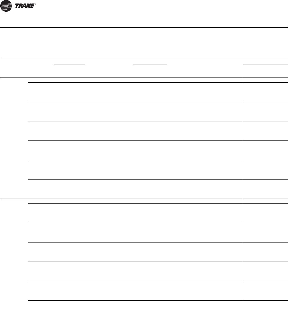
62 UV-PRC003-EN
Performance Data
Table 46. VUV 075–150, electrical performance
Model #
Unit
Voltage
Blower Motor
# Fan
Motors
# Heating
Elements
Electric Heat
Total
FLA
Minimum
Circuit
Ampacity
Overcurrent
Protection
Device
Low FLA Option
FLA
(ea.) HP kW Amp
Total
FLA
Minimum
Circuit
Ampacity
VUVE075 115/60/1 3.5 0.25 1 0 0 0 3.5 4.375 15 2.8 3.5
208/60/1 2.1 0.25 1 0 0 0 2.1 2.625 15 1.68 2.1
208/60/1 2.1 0.25 1 3 4.39 21.1 23.2 29 30 22.78 28.475
208/60/1 2.1 0.25 1 4 5.86 28.2 30.3 37.875 40 29.88 37.35
208/60/1 2.1 0.25 1 6 8.79 42.3 44.4 55.5 60 43.98 54.975
208/60/3 2.1 0.25 1 0 0 0 2.1 2.625 15 1.68 2.1
208/60/3 2.1 0.25 1 3 4.39 12.2 14.3 17.875 20 13.88 17.35
208/60/3 2.1 0.25 1 4 5.86 18.69 20.8 25.9875 30 20.37 25.4625
208/60/3 2.1 0.25 1 6 8.79 24.4 26.5 33.125 40 26.08 32.6
230/60/1 2.1 0.25 1 0 0 0 2.1 2.625 15 1.68 2.1
230/60/1 2.1 0.25 1 3 5.85 24.4 26.5 33.125 40 26.08 32.6
230/60/1 2.1 0.25 1 4 7.8 32.5 34.6 43.25 50 34.18 42.725
230/60/1 2.1 0.25 1 6 11.7 48.8 50.9 63.625 70 50.48 63.1
230/60/3 2.1 0.25 1 0 0 0 2.1 2.625 15 1.68 2.1
230/60/3 2.1 0.25 1 3 5.85 14.1 16.2 20.25 20 15.78 19.725
230/60/3 2.1 0.25 1 4 7.8 21.49 23.6 29.4875 30 23.17 28.9625
230/60/3 2.1 0.25 1 6 11.7 28.1 30.2 37.75 40 29.78 37.225
277/60/1 1.6 0.25 1 0 0 0 1.6 2 15 1.28 1.6
277/60/1 1.6 0.25 1 3 5.82 21 22.6 28.25 30 22.28 27.85
277/60/1 1.6 0.25 1 4 7.8 28.2 29.8 37.25 40 29.48 36.85
277/60/1 1.6 0.25 1 6 11.7 42.2 43.8 54.75 60 43.48 54.35
460/60/3 1.6 0.25 1 0 0 0 1.6 2 15 1.28 1.6
460/60/3 1.6 0.25 1 3 5.85 7 8.6 10.75 15 8.28 10.35
460/60/3 1.6 0.25 1 4 7.8 14.1 15.7 19.625 20 15.38 19.225
460/60/3 1.6 0.25 1 6 11.7 14.1 15.7 19.625 20 15.38 19.225
VUVE100 115/60/1 3.5 0.25 1 0 0 0 3.5 4.375 15 2.8 3.5
208/60/1 2.1 0.25 1 0 0 0 2.1 2.625 15 1.68 2.1
208/60/1 2.1 0.25 1 3 5.86 28.2 30.3 37.875 40 29.88 37.35
208/60/1 2.1 0.25 1 4 7.81 37.5 39.6 49.5 50 39.18 48.975
208/60/1 2.1 0.25 1 6 11.72 56.3 58.4 73 80 57.98 72.475
208/60/3 2.1 0.25 1 0 0 0 2.1 2.625 15 1.68 2.1
208/60/3 2.1 0.25 1 3 5.86 16.3 18.4 23 25 17.98 22.475
208/60/3 2.1 0.25 1 4 7.81 24.79 26.9 33.6125 40 26.47 33.0875
208/60/3 2.1 0.25 1 6 11.72 32.5 34.6 43.25 50 34.18 42.725
230/60/1 2.1 0.25 1 0 0 0 2.1 2.625 15 1.68 2.1
230/60/1 2.1 0.25 1 3 7.8 32.5 34.6 43.25 50 34.18 42.725
230/60/1 2.1 0.25 1 4 10.4 43.3 45.4 56.75 60 44.98 56.225
230/60/1 2.1 0.25 1 6 15.6 65 67.1 83.875 90 66.68 83.35
230/60/3 2.1 0.25 1 0 0 0 2.1 2.625 15 1.68 2.1
230/60/3 2.1 0.25 1 3 7.8 18.8 20.9 26.125 30 20.48 25.6
230/60/3 2.1 0.25 1 4 10.4 28.66 30.8 38.45 40 30.34 37.925
230/60/3 2.1 0.25 1 6 15.6 37.5 39.6 49.5 50 39.18 48.975
277/60/1 1.6 0.25 1 0 0 0 1.6 2 15 1.28 1.6
277/60/1 1.6 0.25 1 3 7.8 28.2 29.8 37.25 40 29.48 36.85
277/60/1 1.6 0.25 1 4 10.4 37.5 39.1 48.875 50 38.78 48.475
277/60/1 1.6 0.25 1 6 15.6 56.3 57.9 72.375 80 57.58 71.975
460/60/3 1.6 0.25 1 0 0 0 1.6 2 15 1.28 1.6
460/60/3 1.6 0.25 1 3 7.8 9.4 11.0 13.75 15 10.68 13.35
460/60/3 1.6 0.25 1 4 10.4 18.8 20.4 25.5 30 20.08 25.1
460/60/3 1.6 0.25 1 6 15.6 18.8 20.4 25.5 30 20.08 25.1
Electrical
UV-PRC003-EN.book Page 62 Tuesday, June 4, 2013 8:59 PM
UV-PRC003-EN 63
Performance Data
VUVE125 115/60/1 7.0 0.25 2 0 0 0 7.0 8.75 15 3.5 4.375
208/60/1 4.2 0.25 2 0 0 0 4.2 5.25 15 3.36 4.2
208/60/1 4.2 0.25 2 3 7.32 35.2 39.4 49.25 50 38.56 48.2
208/60/1 4.2 0.25 2 4 9.76 46.9 51.1 63.875 70 50.26 62.825
208/60/1 4.2 0.25 2 6 14.65 70.4 74.6 93.25 100 73.76 92.2
208/60/3 4.2 0.25 2 0 0 0 4.2 5.25 15 3.36 4.2
208/60/3 4.2 0.25 2 3 7.32 20.3 24.5 30.625 30 23.66 29.575
208/60/3 4.2 0.25 2 4 9.76 31.03 35.2 44.0375 50 34.39 42.9875
208/60/3 4.2 0.25 2 6 14.65 40.7 44.9 56.125 60 44.06 55.075
230/60/1 4.2 0.25 2 0 0 0 4.2 5.25 15 3.36 4.2
230/60/1 4.2 0.25 2 3 9.75 40.6 44.8 56 60 43.96 54.95
230/60/1 4.2 0.25 2 4 13 54.2 58.4 73 80 57.56 71.95
230/60/1 4.2 0.25 2 6 19.5 81.3 85.5 106.875 125 84.66 105.825
230/60/3 4.2 0.25 2 0 0 0 4.2 5.25 15 3.36 4.2
230/60/3 4.2 0.25 2 3 9.75 23.5 27.7 34.625 40 26.86 33.575
230/60/3 4.2 0.25 2 4 13 35.82 40.0 50.025 50 39.18 48.975
230/60/3 4.2 0.25 2 6 19.5 46.9 51.1 63.875 70 50.26 62.825
277/60/1 3.2 0.25 2 0 0 0 3.2 4 15 2.56 3.2
277/60/1 3.2 0.25 2 3 9.75 35.2 38.4 48 50 37.76 47.2
277/60/1 3.2 0.25 2 4 13 46.9 50.1 62.625 70 49.46 61.825
277/60/1 3.2 0.25 2 6 19.5 70.4 73.6 92 100 72.96 91.2
460/60/3 3.2 0.25 2 0 0 0 3.2 4 15 2.56 3.2
460/60/3 3.2 0.25 2 3 9.75 11.7 14.9 18.625 20 14.26 17.825
460/60/3 3.2 0.25 2 4 13 23.5 26.7 33.375 40 26.06 32.575
460/60/3 3.2 0.25 2 6 19.5 23.5 26.7 33.375 40 26.06 32.575
VUVE150 115/60/1 7.0 0.25 2 0 0 0 7.0 8.75 15 3.5 4.375
208/60/1 4.2 0.25 2 0 0 0 4.2 5.25 15 3.36 4.2
208/60/1 4.2 0.25 2 3 8.56 41.2 45.4 56.75 60 44.56 55.7
208/60/1 4.2 0.25 2 4 11.42 54.9 59.1 73.875 80 58.26 72.825
208/60/1 4.2 0.25 2 6 17.13 82.4 86.6 108.25 125 85.76 107.2
208/60/3 4.2 0.25 2 0 0 0 4.2 5.25 15 3.36 4.2
208/60/3 4.2 0.25 2 3 8.56 23.8 28.0 35 40 27.16 33.95
208/60/3 4.2 0.25 2 4 11.42 36.36 40.6 50.7 50 39.72 49.65
208/60/3 4.2 0.25 2 6 17.13 47.5 51.7 64.625 70 50.86 63.575
230/60/1 4.2 0.25 2 0 0 0 4.2 5.25 15 3.36 4.2
230/60/1 4.2 0.25 2 3 11.4 47.5 51.7 64.625 70 50.86 63.575
230/60/1 4.2 0.25 2 4 15.2 63.3 67.5 84.375 90 66.66 83.325
230/60/1 4.2 0.25 2 6 22.8 95 99.2 124 125 98.36 122.95
230/60/3 4.2 0.25 2 0 0 0 4.2 5.25 15 3.36 4.2
230/60/3 4.2 0.25 2 3 11.4 27.4 31.6 39.5 40 30.76 38.45
230/60/3 4.2 0.25 2 4 15.2 41.87 46.1 57.5875 60 45.23 56.5375
230/60/3 4.2 0.25 2 6 22.8 54.8 59.0 73.75 80 58.16 72.7
277/60/1 3.2 0.25 2 0 0 0 3.2 4 15 2.56 3.2
277/60/1 3.2 0.25 2 3 11.4 41.2 44.4 55.5 60 43.76 54.7
277/60/1 3.2 0.25 2 4 15.2 54.9 58.1 72.625 80 57.46 71.825
277/60/1 3.2 0.25 2 6 22.8 82.3 85.5 106.875 125 84.86 106.075
460/60/3 3.2 0.25 2 0 0 0 3.2 4 15 2.56 3.2
460/60/3 3.2 0.25 2 3 11.4 13.7 16.9 21.125 20 16.26 20.325
460/60/3 3.2 0.25 2 4 15.2 27.4 30.6 38.25 40 29.96 37.45
460/60/3 3.2 0.25 2 6 22.8 27.4 30.6 38.25 40 29.96 37.45
Table 46. VUV 075–150, electrical performance (continued)
Model #
Unit
Voltage
Blower Motor
# Fan
Motors
# Heating
Elements
Electric Heat
Total
FLA
Minimum
Circuit
Ampacity
Overcurrent
Protection
Device
Low FLA Option
FLA
(ea.) HP kW Amp
Total
FLA
Minimum
Circuit
Ampacity
Electrical
UV-PRC003-EN.book Page 63 Tuesday, June 4, 2013 8:59 PM
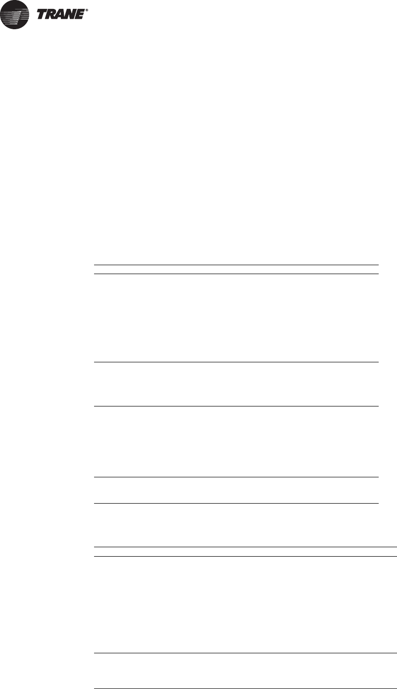
64 UV-PRC003-EN
Controls
Why Trane Controls?
Whether involved in a retrofit or in new construction applications, Trane has the control design to
fit the systems requirements. The broad range of control packages offer a range from a field
convertible end-device package, to a complete building automation system solution with LonTalk®
controls.
The good news is Trane® controls are factory-mounted, -wired, -tested and configured or
programmed with Trane® application expertise to provide comfort, efficiency, and reliability, as
well as, single-source warranty and service. With Trane’s integrated controls, the installed costs are
lower because the equipment has turn-key factory controls and every component of the system is
optimized to fit with the controller. Trane installs not only the controller, but also the hardware that
works intimately with the controller to allow the system to function properly (i.e., piping package,
valves, dampers, actuators, etc.). When a classroom unit ventilator with Trane® controls arrives to
the jobsite, it is completely ready for quick installation.
Table 47. Controller input/output summary
ZN520 UC400
Binary Outputs X
3-Speed Fan X X
2-Position Hydronic Valve X X
2-Position Fresh Air Damper X
1-Stage Electric Heat X X
3-Wire Economizer Damper X X
3-Wire Hydronic Valve X X
2-Stage Electric Heat X X
Reheat (hydronic or electric) X X
Generic X (a)
(a)The generic input and output are for use with a Tracer Summit system only.
Binary Inputs
Condensate Overflow Detection X X
Low Temperature Detection X X
Occupancy X X
Generic Input X (a)
Analog Inputs
Zone Temperature X X
Setpoint X X
Fan Mode: Auto, High, Medium, Low X X
Entering Water X X
Discharge Air X X
Outside Air X X
Generic X (a)
Analog Outputs
Variable speed fan X
Field supplied analog valves X
Table 48. Controller function summary
ZN520 UC400
Control Functions
Entering Water Temp. Sampling (Purge) X X
Auto Changeover X X
Fan Cycling
Warm-Up X
Pre-Cool X
Data Sharing (Master/Slave) X
Random Start X X
Dehumidification X X
Single Zone VAV X
Staged Capacity (2-Stage Electric Supplementary) X X
Other Functions
Manual Test X in TU
Maintenance Timer X X
Setpoint Limits X X
UV-PRC003-EN.book Page 64 Tuesday, June 4, 2013 8:59 PM
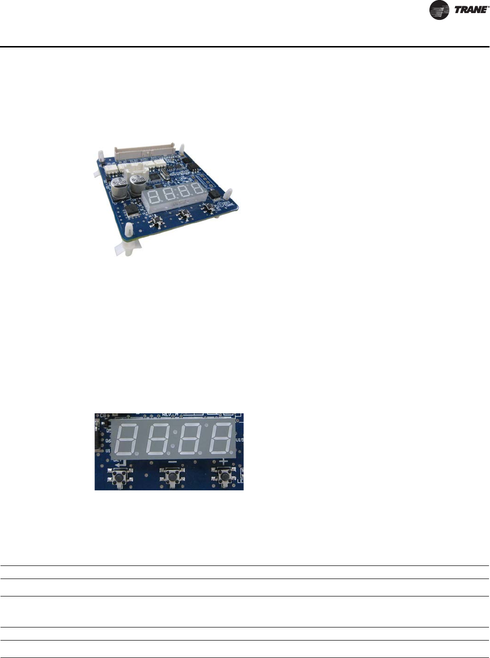
UV-PRC003-EN 65
Controls
ECM Engine Controller
The Electronically Commutated Motor (ECM) engine controls and reports the performance of up
to two Trane Brushless DC (BLDC) motors.
• The engine also coordinates the operation of the fan in response to electric heat behavior and
electric behavior in response to hydronic heat behavior.
• The engine incorporates a user interface that allows adjustment of certain unit parameters and
provides constant feedback on motor operation.
• The engine integrates service and troubleshooting tools.
• The engine integrates a versatile configurable auxiliary temperature sensor.
• The engine incorporates various safety and lockout features, such as maintaining proper fan
speeds if electric heat is called for.
Status Display
The ECM engine board contains a four-digit, seven-segment display that is used to present
information in a format close to real-world language, while having a small-form factor. Most
characters are immediately recognizable; however, please consult Table 49 and Table 50 for the
graphical representation of each alphanumeric character.
Figure 20. ECM engine controller
Figure 21. Status display
Table 49. Screen representation of alphabetical characters
ABCDEFGHI JKLMNOPQRSTUVWXYZ
Table 50. Screen representation of numeric characters
1234567890
ECM Engine Controller
UV-PRC003-EN.book Page 65 Tuesday, June 4, 2013 8:59 PM
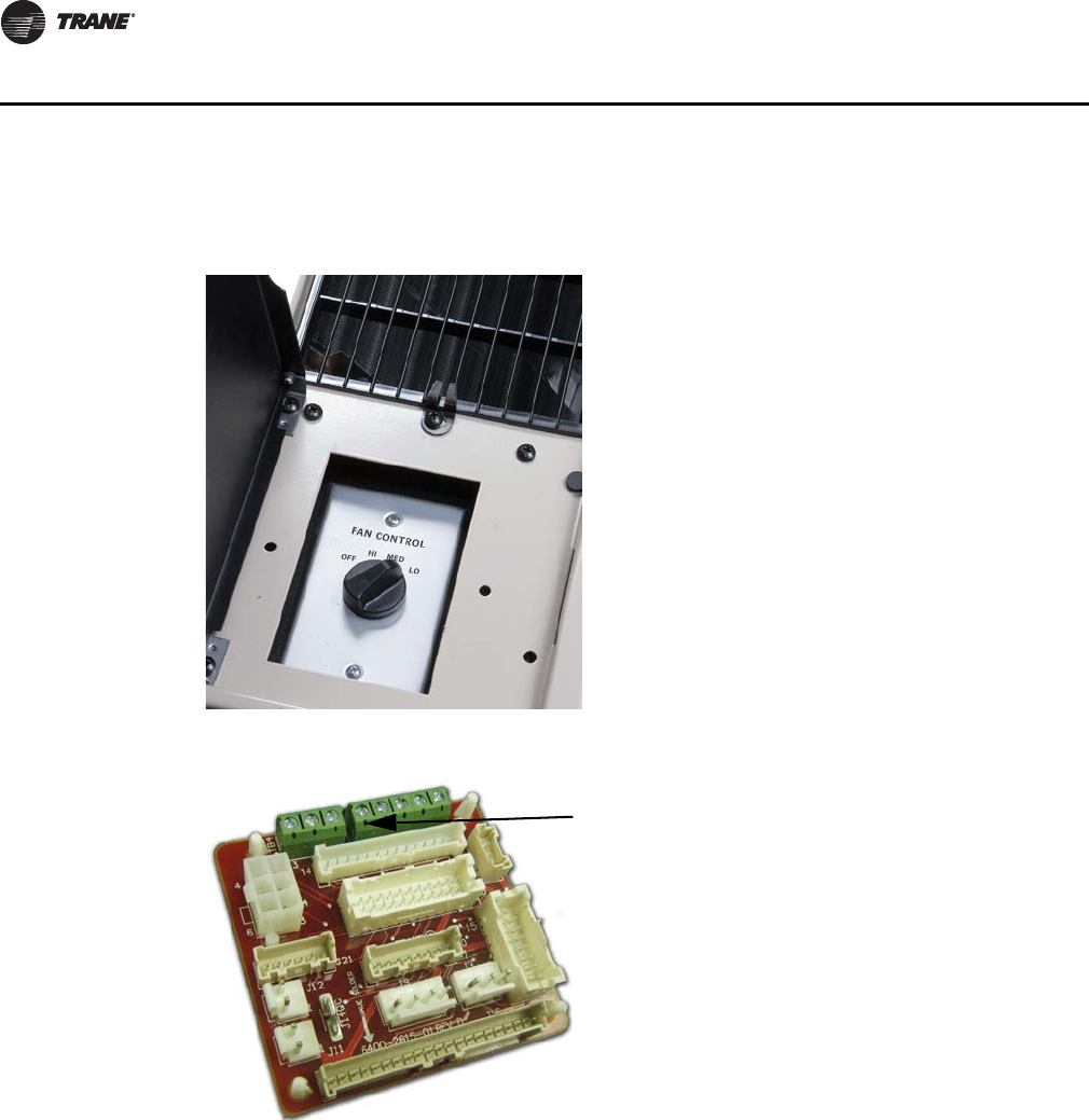
66 UV-PRC003-EN
Controls
Fan Speed Switch
Figure 22. Fan speed switch
Figure 23. Adapter board
Note: Customer Low-Voltage Interface for
Fan Speeds, Variable Fan Speed, and
24 Vac Supply
End Device Controls
UV-PRC003-EN.book Page 66 Tuesday, June 4, 2013 8:59 PM

UV-PRC003-EN 67
Controls
The adapter allows direct customer interfacing through the use of terminal strips. Standard
interfacing includes:
• Fan Speeds (H, M, L) (for wall mounted fan speed switches)
• Variable speed (0–10V) inputs
The standard adapter board eliminates many separate wiring harnesses in the panel and allows
simple, mistake-proofed single-plug interfacing of:
• The ECM engine controller
•Transformers
•Motors
• Valves
•Dampers
• Electric heat control
• Fan speed switches
• Main power (except electric heat)
The manual fan mode switch is available for fan-coil units that do not have Trane factory-mounted
control packages. This four-position switch (off, high, medium, low) allows manual fan mode
selection and is available unit or wall mounted. The unit-mounted option operates on line voltage.
The wall-mounted option is low-voltage and has three 24-volt relays using a factory-wired
transformer and relays to control the fan motor.
End Device Controls
UV-PRC003-EN.book Page 67 Tuesday, June 4, 2013 8:59 PM
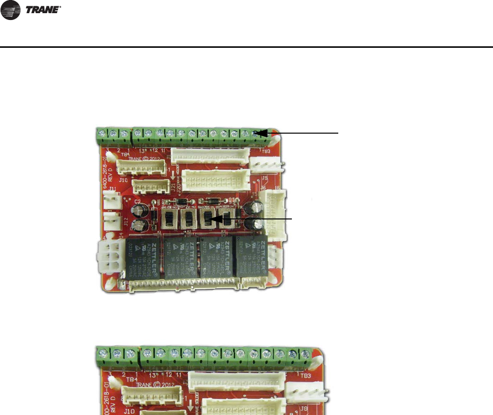
68 UV-PRC003-EN
Controls
Customer Supplied Terminal Interface (CSTI)
The control interface is intended to be used with a field-supplied, low-voltage thermostat or
controller. The control box contains a relay board which includes a line voltage to 24-volt
transformer, quiet contactors (for electric heat units), and an optional disconnect switch. All end
devices are wired to a low-voltage terminal block and are run-tested, so the only a power
connection and thermostat connection is needed to commission the unit. Changeover sensors and
controls are provided whenever a change-over coil is selected. When N.O. valves are selected,
inverting relays are provided for use with standard thermostats.
The CSTI adapter board provides all the hookups of the standard adapter board, but in addition,
provides hookups for valve control (main and auxiliary coils), electric heat control, and damper
control. Screw terminal blocks provide convenient access to fan controls and to end device control.
In addition, a courtesy 10-Vdc supply is provided for use with an external potentiometer or rheostat.
The 10-Vdc supply supports up to 10 mA draw.
Figure 24. CSTI adapter board
Figure 25. CSTI adapter board field connections
1. VSP 10V
2. VSP 0–10V
3. VSP DC COM
1. 24 Vac Y (hot)
2. 24 Vac Y (gnd)
3. High
4. Medium
5. Low
6. V1Op/Cooling
7. V1C1 (not std)
8. Not used
9. Not used
10. V2Op/EH1St/Heating
11. V2C1/EH2St (not std)
12. Damper Open
13. Dmp Cl (not std)
Customer Low-Voltage Interface for
Valves, Electric Heat, Dampers, Fan
Speeds, Variable Fan Speed, and
24 Vac Supply
Valve(s), Electric Heat, and Changeover
Configuration Switches (Factory-Set)
321 1098 765432 1
11
12
13
CSTI
UV-PRC003-EN.book Page 68 Tuesday, June 4, 2013 8:59 PM
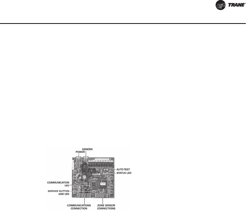
UV-PRC003-EN 69
Controls
Tracer ZN520 Zone Controller
Features Include
• Automatic fan-speed reset
• Automatic ventilation reset
• Active dehumidification
• Manual output test
• Filter maintenance
• Master slave
• Water valve override
• Freeze avoidance
• Interoperability
• Three generic I/O ports
The Tracer ZN520 is a factory-installed, -tested and -commissioned LonTalk® control board
designed to provide control of the classroom unit ventilator and the fan-coil products (see
Figure 26).
The Tracer ZN520 controller is designed to be used in the following applications:
• As part of the Trane Tracer Summit building automation system, the Tracer ZN520 becomes an
important part of the Trane Integrated Comfort system (ICS).
• The Tracer ZN520 can function as a completely standalone controller in situations where a
building automation system (BAS) is not present.
• For situations when a non-Trane BAS is present, the Tracer ZN520 can be where ever a LonTalk
front-end system is present.
Through building management of the HVAC system, optimizing energy consumption becomes
possible at a classroom level. Each unit is capable of functioning independently of one another
during occupied and unoccupied hours of the day. This allows the temperature setpoint and
ventilation setting to be changed automatically based on classroom usage (see Figure 27, p. 70).
Figure 26. Tracer ZN520 control board
Tracer ZN520 (LonTalk)
UV-PRC003-EN.book Page 69 Tuesday, June 4, 2013 8:59 PM
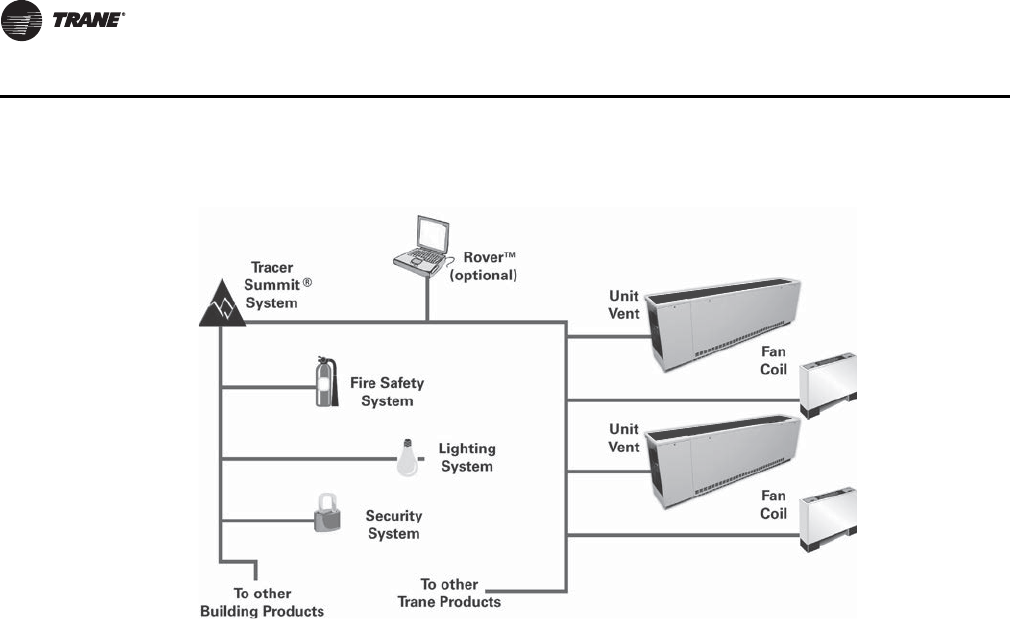
70 UV-PRC003-EN
Controls
Two Systems in One
In an ICS environment, the Tracer ZN520 is pre-designed to install quickly and easily into the
system. Since the controller and the unit are factory tested and commissioned, the start-up time
for the entire system is minimized. Trane becomes the single source of responsibility for the
equipment, unit controls, and building automation system.
As a standalone controller, the Tracer ZN520 is ideally suited for fix-on-fail replacement of units
with old pneumatic controllers, or in situations where a BAS will be added at a later date. Once
power is applied to the controller, it will automatically start up and run based upon the setpoint on
the local zone sensor. An individual time clock can be added to the unit for local scheduling.
The Tracer ZN520 is certified to the interoperable LONMARK® Space Comfort Controller profile. This
allows the controller to be used with another vendor’s BAS and thereby still provide the high quality
of factory installation and testing. In addition, the Tracer ZN520 provides one of the most extensive
interoperable data lists of any controller of its type in the industry.
Tracer ZN520 Features Include
Automatic Fan and Ventilation Reset. With the Tracer ZN520 controller, a multi-speed fan
control for the unit ventilator delivers the airflow output customized to support the cfm space
needs. When less cfm is necessary to meet the load of the classroom (typically 75 to 80 percent of
the time), the equipment operates on low speed. However, if the room temperature rises, the
controller will switch to high speed, and the outside air damper will adjust to satisfy the space
needs. This helps maintain the proper amount of ventilation air to the occupants independent of
the fan speed. As part of the ventilation strategy, the controller will reposition the outside air
damper to confirm the minimum outside air cfm is met at both operating conditions.
Manual Output Test . The Tracer ZN520 controller includes a manual output test function. This
function may be initiated from the blue test push button on the controller or through the Rover™
service tool. This feature is used to manually exercise the outputs in a defined sequence.
The purpose of this test sequence is to verify output and end device operation. The manual output
test function may also be used in the following situations:
• Reset latching diagnostics
• Verify output wiring and operation
Figure 27. Tracer ZN520 system
Tracer ZN520 (LonTalk)
UV-PRC003-EN.book Page 70 Tuesday, June 4, 2013 8:59 PM

UV-PRC003-EN 71
Controls
• Force the water valve(s) open to balance the hydronic system during installation set-up or
service.
Filter Maintenance. Filter status for the controller is based on the cumulative run hours of the
unit fan. The controller compares the amount of fan run time against an adjustable fan run hour
(stored in the controller) to determine when maintenance is recommended for the unit. The run-
hours value may be user edited as required (through Rover). The valid range for the fan run hours
limit is 0 to 5000 hours with a default of 600 hours. Once the run hours limit has been exceeded,
the controller generates a maintenance required diagnostic (unit will not shut-down). The user will
be notified of this diagnostic through the building automation system or when a Trane Service Tool
is communicating with the controller.
Active Dehumidification. On unit ventilators with reheat coils, the Tracer ZN520 can provide
active dehumidification to the classroom. This means that the classroom relative humidity can be
kept below an adjustable setpoint independent outdoor weather conditions. Indoor humidity levels
are recommended by ASHRAE to be kept below 60 percent in order to minimize microbial growth
and the life span of airborne illness causing germs.
Master Slave (Data Sharing). Because the Tracer ZN520 controller utilizes LONWORKS®
technology, the controller can send or receive data (setpoint, heat/cool mode, fan request, space
temperature, etc.) to and from other controllers on the communication link with or without the
existence of a building automation system. This applies to applications where multiple units might
share one zone sensor for both stand-alone (with communication wiring between units) and a
building automation system.
Water Valve Override. The Tracer ZN520 can be commanded via the Rover service tool to open
all hydronic valves 100 percent. This allows for the faster water balancing of each unit and the entire
system when the command is sent globally to all controllers. A properly balanced system is
essential for proper and efficient operation.
Hydronic Coil Freeze Protection (Freeze Avoidance). Unit ventilator systems in cold
climates need to take precautions to avoid hydronic coil freeze-up. The Tracer ZN520 does this from
three different aspects. Any of these methods of protections will result in the unit fan being
disabled, the outside air damper being shut, and the hydronic valves being opened 100 percent.
The three methods of freeze avoidance include:
1. A binary freeze protection thermostat is mounted on the coil and will cause a latching diagnostic
if the coil temperature falls below 35°F.
2. An analog discharge air sensor monitors the temperature of the air coming off of the coil and
if the temperature falls below 40°F the outside air damper is closed, the fan is turned off and
the valves are fully opened.
3. When in the unoccupied mode the Tracer ZN520 has an adjustable freeze avoidance setpoint.
If the outside air temperature is below the setpoint the unit will open the valves to allow water
to flow through the coils.
Interoperability. Interoperability allows the owner freedom to select multiple vendors, and
multiple products. With this advantage, the owner can choose the best products, the best
application, and the best service from a variety of suppliers to meet their evolving building control
needs in a cost effective manner.
Generic Binary Input/Output. The three generic binary inputs/outputs are not part of the
normal control, but are actually controlled through the Tracer Summit system (when present) to
issue commands to the Tracer ZN520 control to turn the generic inputs/outputs of add-on
equipment (such as baseboard heating, exhaust fans, occupancy sensor, lighting, etc.) on and off.
This binary port is not affected when other binary diagnostics interrupt unit operation.
Tracer ZN520 (LonTalk)
UV-PRC003-EN.book Page 71 Tuesday, June 4, 2013 8:59 PM
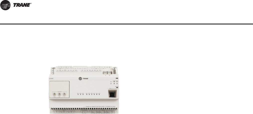
72 UV-PRC003-EN
Controls
Tracer UC400
The Tracer UC400 controller delivers single zone VAV control and can be used in a stand-alone
application or as part of a Trane Integrated Comfort System (ICS).
In the stand-alone configuration, Tracer UC400 receives operation commands from the zone sensor
and/or the auto changeover sensor (on auto changeover units). The entering water temperature is
read from the auto changeover sensor and determines if the unit is capable of cooling or heating.
The zone sensor module is capable of transmitting the following information to the controller:
• Timed override on/cancel request
• Zone setpoint
• Current zone temperature
• Fan mode selection (off-auto-high-med-low)
For optimal system performance, unit ventilators can operate as part of an Integrated Comfort
System (ICS) building automation system controlled by Tracer Summit. The controller is linked
directly to the Summit control panel via a twisted pair communication wire, requiring no additional
interface device (i.e., a command unit). The Trane ICS system can monitor or override Tracer UC400
control points. This includes such points as temperature and output positions.
Tracer UC400 Zone Controller Features Include
• Single Zone VAV
• Automatic ventilation reset
• Active dehumidification
• Filter maintenance
• Water valve override
• Freeze avoidance
• Interoperability
• Unused I/O can be as generic I/O
The Tracer UC400 is a factory-installed, -tested, and -commissioned BACnet® MS/TP control
designed to provide control of the classroom unit ventilator (see Figure 28). The Tracer UC400
controller is designed to be used in the following applications: as stand-alone operation, part of the
Trane Tracer SC building automation system, or part of another BACnet MS/TP Building
Automation System. The Tracer UC400 can function as a completely standalone controller in
situations where a building automation system (BAS) is not present.
The Tracer UC400 is designed to install quickly and easily into the system. Since the controller and
the unit are factory-tested and -commissioned, the start-up time for the entire system is minimized.
Trane becomes the single source of responsibility for the equipment, unit controls, and building
automation system. As a standalone controller, the Tracer UC400 is ideally suited for fix-on-fail
Figure 28.
Tracer UC400
UV-PRC003-EN.book Page 72 Tuesday, June 4, 2013 8:59 PM
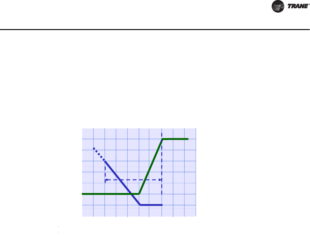
UV-PRC003-EN 73
Controls
replacement of units with old pneumatic controllers, or in situations where a BAS will be added at
a later date. Once power is applied to the controller, it will automatically start up and run based
upon the setpoint on the local zone sensor. An individual time clock can be added to the unit for
local scheduling. The Tracer UC400 is BTL listed as B-ASC profile. This ensures the controller to be
used with other BACnet® building automation systems.
Tracer UC400 Features Include
Single Zone VAV with Fully Modulating Fan Speed. The Tracer UC400 will minimize fan
speed, and in turn energy usage, by only delivering the air flow needed.
Ventilation Reset. With the Tracer UC400 the unit ventilator delivers the airflow the space needs.
When the air flow adjusts the outside air damper will also adjust to satisfy the space needs. This
helps maintain the proper amount of ventilation air to the occupants independent of the fan speed.
As part of the ventilation strategy, the controller will reposition the outside air damper to confirm
the minimum outside airflow is met at both operating conditions.
Filter Maintenance. Filter status for the controller is based on the cumulative run hours of the
unit fan. The controller compares the amount of fan run time against an adjustable fan run hour
(stored in the controller) to determine when maintenance is recommended for the unit. The run-
hours value may be user edited as required. The valid range for the fan run hours limit is 0 to
5000 hours with a default of 600 hours. Once the run hours limit has been exceeded, the controller
generates a maintenance required diagnostic (unit will not shut-down). The user will be notified
of this diagnostic through the building automation system or when a Trane® service tool is
communicating with the controller.
Active Dehumidification. On unit ventilators with reheat coils, the controller can provide active
dehumidification to the classroom. This means that the classroom relative humidity can be kept
below an adjustable setpoint independent outdoor weather conditions. Indoor humidity levels are
recommended by ASHRAE to be kept below 60 percent in order to minimize microbial growth and
the life span of airborne illness causing germs.
Hydronic Coil Freeze Protection (Freeze Avoidance). Unit ventilator systems in cold
climates need to take precautions to avoid hydronic coil freeze-up. The controller does this from
three different aspects. Any of these methods of protections will result in the unit fan being
disabled, the outside air damper being shut, and the hydronic valves being opened 100 percent.
The three methods of freeze avoidance include:
1. A binary freeze protection thermostat is mounted on the coil and will cause a latching diagnostic
if the coil temperature falls below 35°F.
Figure 29. Cool mode nominal hydronic cooling control
t
(°F)
80
Fa
n
Max. Flow = 100% 100
s
etpoin
t
70
80
60
n
speed
0
100
%
Cooling
e
temp
s
60
40
comma
n
0
100
%
Cooling
20
ischarg
e
50
n
d (%)
Min. discharge
setpoint = 50°F
Min. Flow = 0% 0
D
45 Csp
Siblld
No cooling load Design cooling
load (demand)
S
pace sens
ibl
e
l
oa
d
load
(demand)
Tracer UC400
UV-PRC003-EN.book Page 73 Tuesday, June 4, 2013 8:59 PM
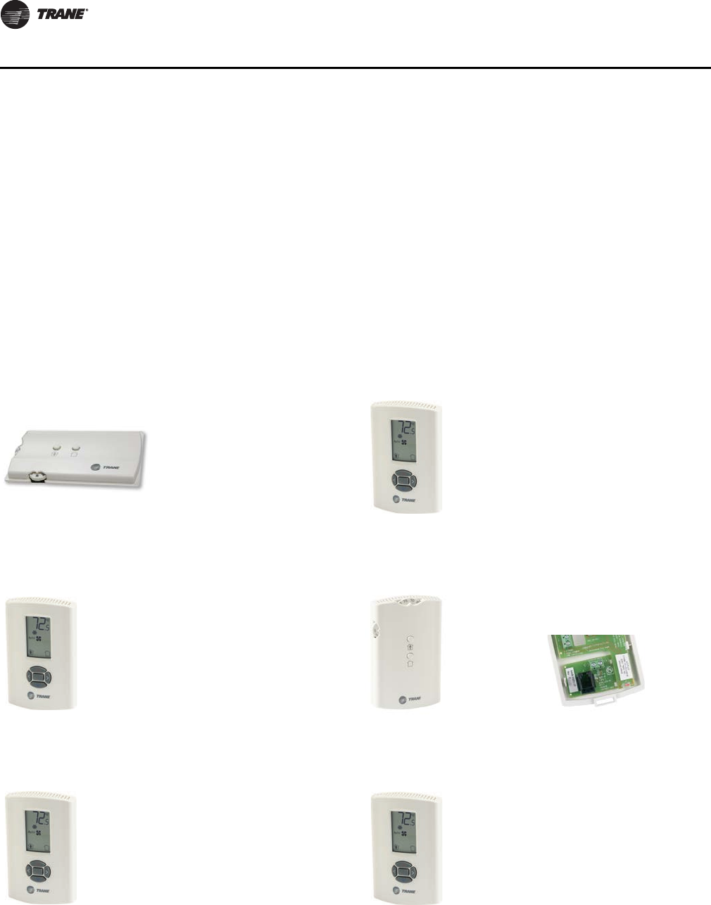
74 UV-PRC003-EN
Controls
2. An analog discharge air sensor monitors the temperature of the air coming off of the coil and
if the temperature falls below 40°F the outside air damper is closed, the fan is turned off and
the valves are fully opened.
3. When in the unoccupied mode, the controller has an adjustable freeze avoidance setpoint. If the
outside air temperature is below the setpoint, the unit will open the valves to allow water to flow
through the coils.
Zone Sensors
Zone sensors are available as either unit, wall, or split-mounted options for design flexibility. Unit
ventilators with the unit-mounted zone sensor option include a thermistor in the unit’s return air
path. Wall-mounted zone sensor options have an internal thermistor. Zone sensors operate on
24 Vac.
Figure 30. Unit mtd temp sensor
(SP, OCC/UNOCC, OALMH)
(Electric heat with auto and off speeds)
Figure 31. Unit mtd display sensor
(SP, OCC/UNOCC, COMM)
Figure 32. Unit mtd display sensor
(SP, OCC/UNOCC, COMM)
Figure 33. Wall mtd temp sensor
(SP, OCC/UNOCC, OALMH, COMM)
Figure 34. Wall mtd display sensor
(SP, OCC/UNOCC, COMM)
Figure 35. Wall mtd display sensor
(SP, OCC/UNOCC, COMM)
X13790844-01 (unit)
X13790886-04 (unit; 3-speed)
X13790886-03 (unit; 2-speed)
X13790842-02 (wall)
X13651467-01 (comm)
X13790886-04 (wall; 3-speed)
X13790886-03 (wall; 2-speed)
Zone Sensors
UV-PRC003-EN.book Page 74 Tuesday, June 4, 2013 8:59 PM
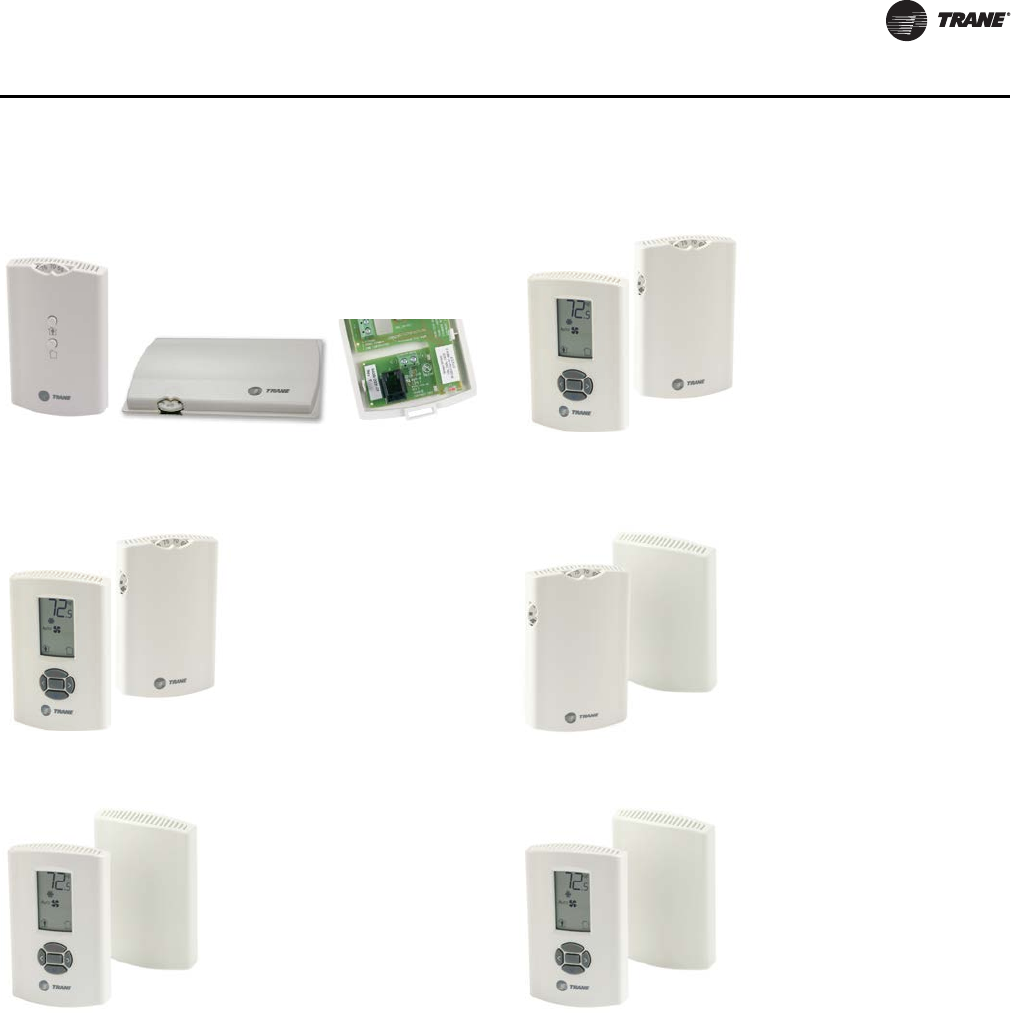
UV-PRC003-EN 75
Controls
Figure 36. Unit mtd FSS (OALMH),
wall mtd temp sensor
(SP, OCC/UNOCC, COMM)
Figure 37. Unit mtd FSS (OALMH),
wall mtd display temp sensor
(SP, OCC/UNOCC, COMM)
Figure 38. Unit mtd FSS (OLH),
wall mtd display temp sensor
(SP, OCC/UNOCC, COMM)
Figure 39. Wireless temp sensor
(SP, OCC/UNOCC, OALMH, COMM)
Figure 40. Wireless temp sensor with display
(SP, OCC/UNOCC, COMM)
Figure 41. Wireless temp sensor with display
(SP, OCC/UNOCC, COMM)
X13511527-01 (wall)
X13790849-01 (unit)
X13651467-01 (comm)
X13790886-04 (wall)
X13790841-02 (unit)
X13790886-03 (wall)
X13790475-01 (unit)
X13790492-01 (wall)
X13790855-01 (unit)
X13790822-04 (wall)
X13790855-01 (unit; 3-speed)
X13790822-01 (wall)
X13790855-01 (unit; 2-speed)
Zone Sensors
UV-PRC003-EN.book Page 75 Tuesday, June 4, 2013 8:59 PM
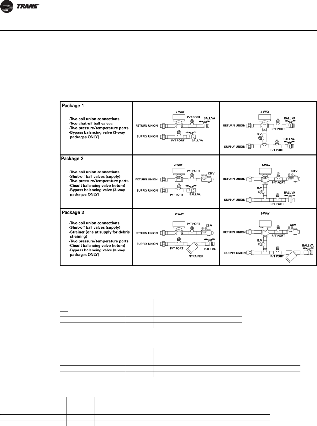
76 UV-PRC003-EN
Controls
Valves/Piping Package
Control valves are mounted in a factory piping package to include unions at the coil, p/t ports on
the supply and return lines, and shut-off ball valve on the supply and return.
Cooling and heating coil valves are only available as 3-point modulating, non-spring return type
valves. The ambient temperature range is -32°F to 150°F.
Water Pressure Drops in feet for Unit Vent 2- and 3-way Piping Packages
Table 51. 1.9 Cv-rated valves in 1/2-in. piping packages
Piping package Cv rating
Gallons per minute
234567
1Basic package 1.9 3.2 7.1 12.6 19.5 28.0 38.1
2with CBV 1.9 5.2 11.7 20.7 32.3 46.4 63.1
3with strainer and CBV 1.9 5.5 12.4 22.0 34.2 49.2 66.8
Table 52. 4.7 Cv-rated valves in 1/2-in. piping packages
Piping package Cv rating
Gallons per minute
567891011121314
1Basic package 4.7 4.5 6.3 8.5 11.013.716.820.223.927.932.1
2with CBV 4.7 17.2 24.7 33.5 43.6 55.1 67.9 – – – –
3with strainer and CBV 4.7 19.1 27.4 37.2 48.5 61.3 75.5 – – – –
Table 53. 6.6 Cv-rated valves in 3/4-in. piping packages
Piping package Cv rating
Gallons per minute
9 1011121314151617181920
1Basic package 6.6 4.8 5.9 7.1 8.4 9.8 11.413.014.816.718.720.823.0
2with CBV 6.6 16.820.725.129.834.940.546.5– – – – –
3with strainer and CBV 6.6 21.226.231.737.744.251.258.8– – – – –
Piping Valve Options
UV-PRC003-EN.book Page 76 Tuesday, June 4, 2013 8:59 PM
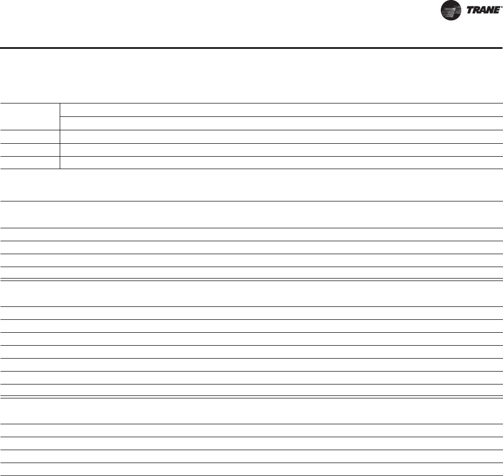
UV-PRC003-EN 77
Controls
Table 54. Control valve pressure drop (feet)
2- or 3-way
water valves
Gallons per minute
2 3 4 5 6 7 8 9 10 11 12 13 14 15 16 17 18 19 20
1/2-in. - 1.9 Cv 2.85 6.42 11.41 17.82 25.67 34.94 – – – – – – – – – – – – –
1/2-in. - 4.7 Cv – – – 2.73 3.93 5.35 6.99 8.84 10.92 13.21 15.72 18.45 21.4 24.56 27.95 – – – –
3/4-in. - 6.6 Cv – – – – – – – 3.51 4.33 5.25 6.24 7.33 8.50 9.75 11.10 12.53 14.04 15.65 17.34
Table 55. Vertical unit ventilator valve offering
2-position
2-way 3-way
1/2-in. 2-way, 1.9 Cv Hydronic - Normally Open - Close off 30 psi 1/2-in. 3-way, 1.9 Cv Hydronic - Close off 28 psi
3/4-in. 2-way, 3.5 Cv Hydronic - Normally Closed - Close off 20 psi 3/4-in. 3-way, 7.0 Cv Hydronic - Close off 10 psi
3/4-in. 2-way, 3.5 Cv Hydronic - Normally Open - Close off 20 psi
1.0-in. 2-way, 8.0 Cv Steam Normally Open - close off 15 psi; 1.0 NPTI
3-wire modulating
2-way 3-way
1/2-in. 2-way, 1.9 Cv Hydronic - Low Cv - heat 1/2-in. 3-way, 1.5 Cv Hydronic - Low Cv - cooling
1/2-in. 2-way, 3.3 Cv Hydronic - Low Cv - cooling 1/2-in. 3-way, 3.8 Cv Hydronic - Med Cv - cool/heat
3/4-in. 2-way, 4.7 Cv Hydronic - Med Cv - cool/heat 3/4-in. 3-way, 6.6 Cv Hydronic - High Cv - cool/heat
1.0-in. 2-way, 6.6 Cv Hydronic - High Cv - cool/heat
1/2-in. 2-way, 1.8 Cv Steam Only 1/2 NPTI
1/2-in. 2-way, 4.6 Cv Steam Only 1/2 NPTI
3/4-in. 2-way, 7.3 Cv Steam Only 3/4 NPTI
2–10 Vdc modulating
2-way 3-way
1/2-in. 2-way, 1.9 Cv Hydronic - Low Cv - heat 1/2-in. 3-way, 1.5 Cv Hydronic - Low Cv - cooling
1/2-in. 2-way, 3.3 Cv Hydronic - Low Cv - cooling 1/2-in. 3-way, 3.8 Cv Hydronic - Med Cv - cool/heat
3/4-in. 2-way, 4.7 Cv Hydronic - Med Cv - cool/heat 3/4-in. 3-way, 6.6 Cv Hydronic - High Cv - cool/heat
1.0-in. 2-way, 6.6 Cv Hydronic - High Cv - cool/heat
Piping Valve Options
UV-PRC003-EN.book Page 77 Tuesday, June 4, 2013 8:59 PM
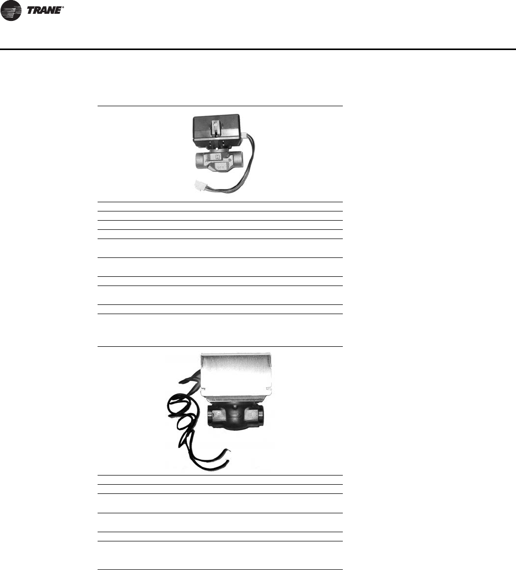
78 UV-PRC003-EN
Controls
Table 56. 3-Wire modulating water valve specifications
Power supply 24 Vac - 50/60 Hz
Power consumption 4 W
Maximum duty cycle 15%
Nominal timing 120 sec
Operating ambient temperature 0°C to 65°C
32°F to 150°F
Min/Max fluid temperature 1°C to 95°C
34°F to 203°F
Operating pressure differential Maximum - 4 bar (60 psi)
Pressure rating Static - 20 bar (300 psi)
Burst - 100 bar (1500 psi)
Flow characteristic Linear
Table 57. Isolation valve specifications
Power supply 24 Vac - 50/60 Hz
Power consumption 5 W
Maximum fluid temperature 94°C
200°F
Minimum fluid temperature 1°C
34°F
Maximum operating pressure 300 psi
Maximum close-off pressure
1/2 in. = 30 psi
3/4 in.= 20 psi
1 in.= 15 psi
Piping Valve Options
UV-PRC003-EN.book Page 78 Tuesday, June 4, 2013 8:59 PM
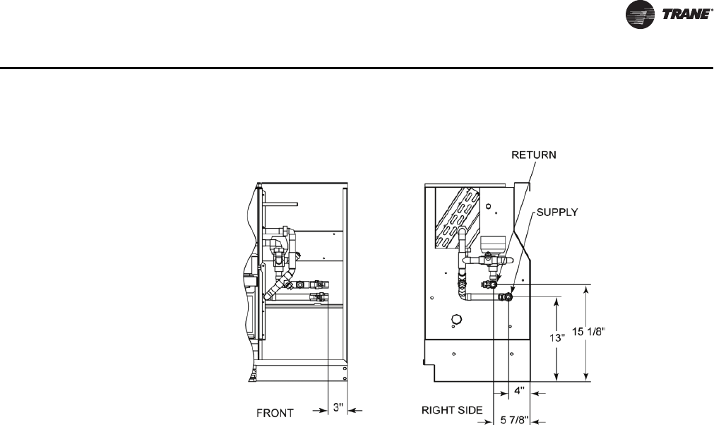
UV-PRC003-EN 79
Controls
Figure 42. Dimensional data for right hand piping with 3-way valve (typical)
Piping Valve Options
UV-PRC003-EN.book Page 79 Tuesday, June 4, 2013 8:59 PM
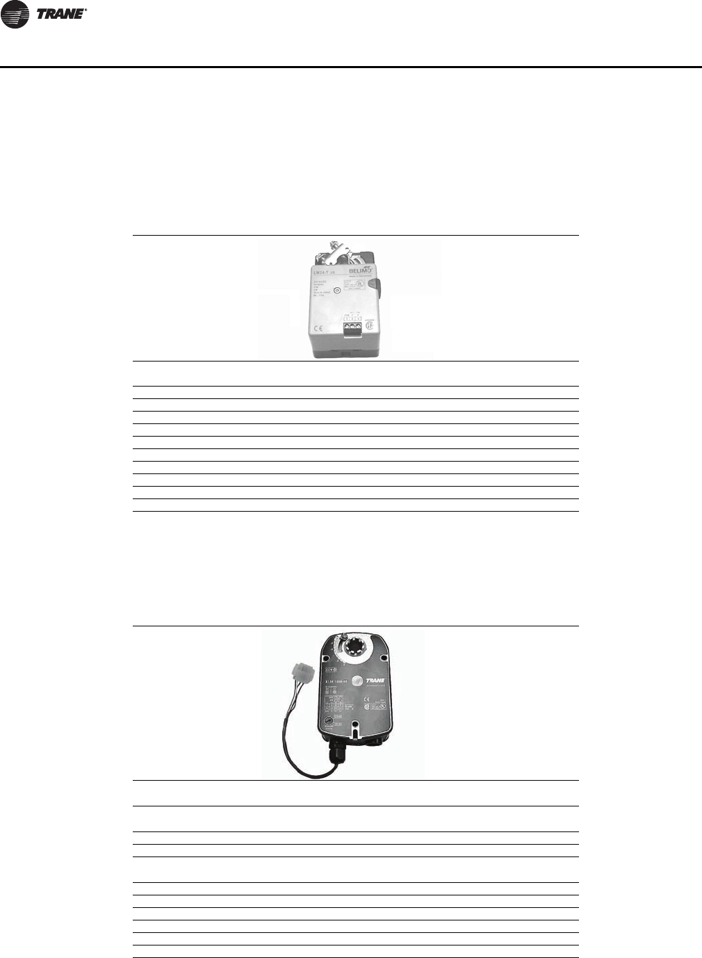
80 UV-PRC003-EN
Controls
Face and Bypass Damper Actuator
An optional face and bypass actuator is 24 volt, 3-point modulating, non-spring return. In-coming
power is 24 Vac with a consumption of 2 watts. Maximum torque of 35 in·lb.
Note: Face and bypass is available with all units ventilator coils, with exception of DX and electric
heat.
Outside/Return-Air Damper Actuator
Optional outside-air/return-air actuator is spring return and takes a 3-point floating signal.
A 2–10 Vdc option is also available. It provides 25 in·lb of torque. The power consumption is 7 VA
with temperature limits of -25°F to 125°F.
Table 58. Face and bypass actuator specification
Power supply 24 Vac ±20% - 50/60 Hz
24 Vac ±10%
Power consumption 2 W
Transformer sizing 3 VA (class 2-power source)
Angle of rotation Maximum 95°, adjustable with mechanical stop
Torque 35 in·lb
Direction of rotation Reversible with switch L/R
Position indication Clip-on indicator
Run time (nominal) 90-second constant
Manual override External push button
Noise level Less than 35 dB
Control signal 3-point floating
Table 59. Outside air actuator specifications
Power supply 24 Vac ±20% - 50/60 Hz
24 Vac ±10%
Power consumption Running: 2.5 W
Holding: 1 W
Transformer sizing 5 VA (class 2-power source)
Overload protection Electronic throughout 0 to 95° rotation
Control signal 2 to 10 Vdc
3-point floating with Trane® controls
Angle of rotation Maximum 95°, adjustable with mechanical stop
Torque 35 in·lb
Direction of rotation Spring return reversible with CW/CCW mounting
Position indication Visual indicator, 0 to 95°
Run time (nominal) 90-second constant (independent of load)
Noise level Running: 30 dB
Actuators
UV-PRC003-EN.book Page 80 Tuesday, June 4, 2013 8:59 PM
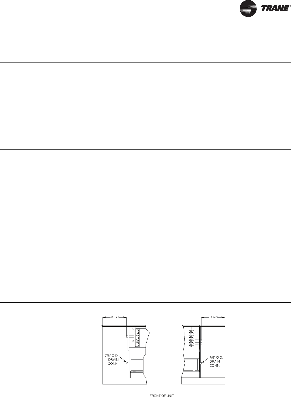
UV-PRC003-EN 81
Jobsite Connections
Coil Type/Specification Header Sizes
Hydronic Main/Auxiliary Reheat Coils
(Cooling Coil or Heating/Cooling Changeover Coil)
• Wavy plate finned.
• Hydrostatically tested at 350 psig.
• All piping packages for the main coil and auxiliary reheat coil assemblies are always
supplied as a 3/4 in. package.
• 3/4 in. Nominal
• 7/8 in. ID
Hydronic Auxiliary Preheat Coils
(Heating Coil)
• Wavy plate finned.
• Hydrostatically tested at 350 psig.
• All piping packages for the auxiliary preheat coil assemblies are always supplied as
a 1/2 in. package.
• 1/2 in. Nominal
• 5/8 in. I.D.
Steam Heating Coils
• 1-row, tube-in-tube distributing coil.
• Piping packages for steam coils are field provided.
• Equipment specified with Trane controls will benefit from an optional 2-position
isolation valve (Main Coil) to be used for close-off of the steam coil when the damper
is in full bypass position.
• The modulating piping valve (option) is shipped loose and field installed.
• 1 in. FNPT
Electric Heat Coils
• Electric preheat coils consist of special finned element for maximum life, heat transfer
and safety.
• Units include a high temperature cut-out with a continuous sensing element. This
device interrupts electrical power whenever excessive temperatures are sensed along
the leaving air side of the coil.
• Power connection is made in the right-hand end pocket.
• A circuit breaker option is available through the equipment model number.
Direct Expansion (DX) Coils
(Refrigerant Cooling Coil)
• The DX refrigerant coil includes a factory mounted thermal expansion valve (TXV) and
equalizing tube, 24 Vac transformer, time delay relay, frost detection, outside air
sensor.
• TXV is sized for R-410A refrigerant. The type of coil is order specific through the unit
model number selection.
• 3/8 in. OD liquid line
• 7/8 in. OD suction line
Figure 43. Coil header location
UV-PRC003-EN.book Page 81 Tuesday, June 4, 2013 8:59 PM
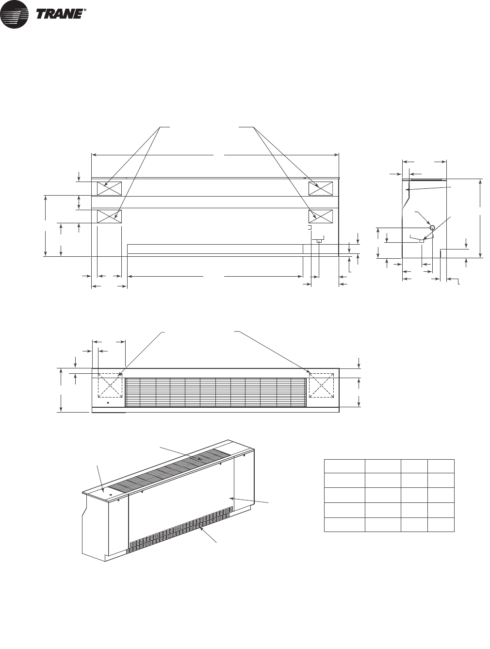
82 UV-PRC003-EN
Dimensional Data
Standard Depth Unit
UNIT SIZE
075
100
125
150
NO. FANS
2
2
4
4
A
69"
81"
93"
105"
B
42"
54"
66"
78"
NOTE:
1. THE UNIT LENGTH DOES NOT INCLUDE 5/8" END PANELS.
2. THE POWER CONNECTION IS MADE IN THE LEFT HAND
END POCKET FOR ALL OPTIONS BUT ELECTRIC HEAT.
3. THE POWER CONNECTION FOR ELECTRIC HEAT OPTION
IS MADE IN THE RIGHT HAND END POCKET.
8 1/8"
B
A
(4)K.O. FOR PIPING
OR ELECTRICAL
FRESH AIR OPENING (OPTIONAL)
5 3/4"
5"
21/4"
13 1/2"
9"
12 1/2"
22 5/8"
3/4"
3 3/4"
BACK VIEW
12 1/4"
FRONT OF UNIT
GRILLE
RETURN AIR
(OPTIONAL)
UNIT MOUNTED
FAN SWITCH
(OPTIONAL)
2"
21/4"
16 5/8"
(2)9" x 9"[229mm x 229mm]
KNOCKOUTS IN BOTTOM
10 7/8"
3 3/4"
TOP VIEW
13"
5 1/4"
9 1/4"
14 3/8"
7"
21/4"
21/2"
23/8"
30"
SIDE VIEW
7/8" O.D.
AUX.
DRAIN CONN.
(optional)
PIPE
CHASE
11"
9 1
/
4
"
7/8" O.D.
DRAIN CONN.
16 5/8"
UV-PRC003-EN.book Page 82 Tuesday, June 4, 2013 8:59 PM
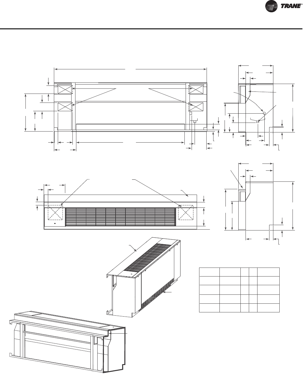
UV-PRC003-EN 83
Dimensional Data
UNIT SIZE
075
100
125
150
NO. FANS
2
2
4
4
A
69"
81"
93"
105"
B
42"
54"
66"
78"
C
25" to 29"
25" to 29"
25" to 29"
25" to 29"
NOTE:
1. THE UNIT LENGTH DOES NOT INCLUDE 5/8" END PANELS.
2. THE POWER CONNECTION IS MADE IN THE LEFT HAND
END POCKET FOR ALL OPTIONS BUT ELECTRIC HEAT.
3. THE POWER CONNECTION FOR ELECTRIC HEAT OPTION
IS MADE IN THE RIGHT HAND END POCKET.
14 3/8"
21/4"
21/2"
16 5/8"
23/8"
30"
21 1/4"
SIDE VIEW
Depicting Step-down
Falseback
18"
C
STEP-DOWN
IS IN 1"
INCREMENTS
21/4"
21/2"
16 5/8"
23/8"
30"
21 1/4"
SIDE VIEW
18"
5 1/4"
7"
PIPE
CHASE
14 3/8"
11"
9 1/4"
8
"
2
1
1
1
/
2
"
3
3
0
0
"
PIPE
C
HA
S
E
7/8" O.D.
DRAIN CONN.
7/8" O.D.
AUX.
DRAIN CONN.
(optional)
FRONTOFUNIT
RETURN AIR
(OPTIONAL)
FALSEBACK
A
(4)K.O. FOR PIPING
OR ELECTRICAL
5 3/4"
5"
9"
12 1/2"
22 5/8"
21/4"
BACK VIEW
8 1/8"
12 1/4"
B
FRESH AIR OPENING (OPTIONAL)
13 1/2"
3/4"
3 3/4"
STEP-DOWN
FALSEBACK
FOR RETROFIT
APPLICATIONS
WHERE WINDOW
SEAL MAY INTERFERE
WITH UNIT INSTALLATION
(OPTIONAL)
STEP-DOWN
FALSEBACK
4. THE UNIT SHOWN INCLUDES THE INSULATED HORIZONTAL
BAFFLE OPTION.
2"
21/4"
(2)9" x 9"[229mm x 229mm]
KNOCKOUTS IN BOTTOM
10 7/8"
3 3/4"
TOP VIEW
13"
FALSEBACK
Falseback Unit
UV-PRC003-EN.book Page 83 Tuesday, June 4, 2013 8:59 PM
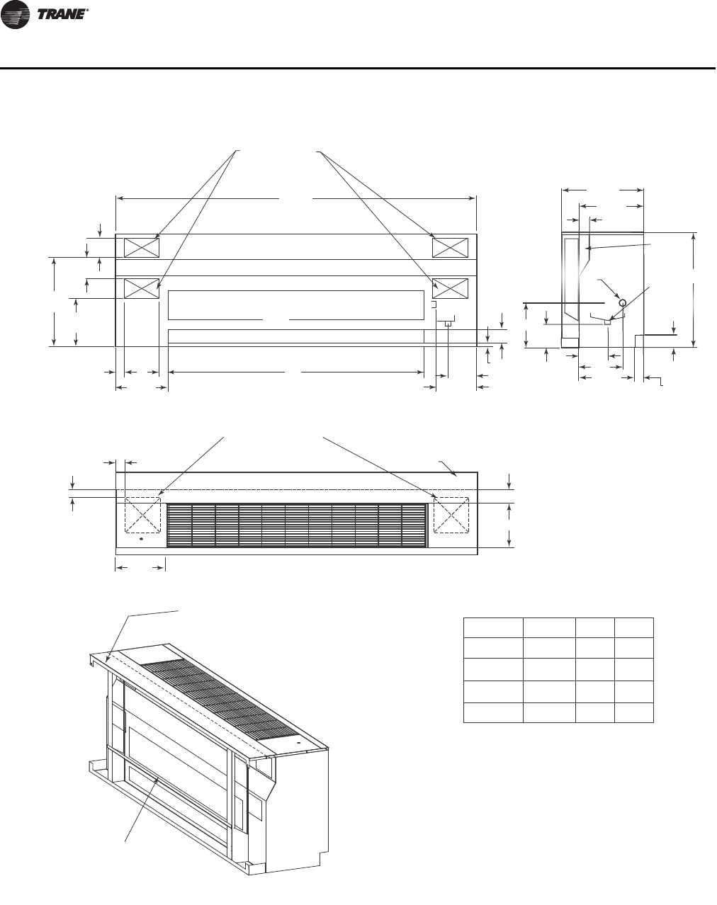
84 UV-PRC003-EN
Dimensional Data
UNIT SIZE
075
100
125
150
NO. FANS
2
2
4
4
A
69"
81"
93"
105"
B
42"
54"
66"
78"
NOTE:
1. THE UNIT LENGTH DOES NOT INCLUDE 5/8" END PANELS.
2. THE POWER CONNECTION IS MADE IN THE LEFT HAND
END POCKET FOR ALL OPTIONS BUT ELECTRIC HEAT.
3. THE POWER CONNECTION FOR ELECTRIC HEAT OPTION
IS MADE IN THE RIGHT HAND END POCKET.
21/2"
16 5/8"
23/8"
30"
21 1/4"
SIDE VIEW
7"
PIPE
CHASE
14 3/8"
21/4"
5 1/4"
11"
9 1/4"
2
3
/
8
"
9
1
/
4"
2
1
/
2
"
3
0
"
CHASE
7/8" O.D.
DRAIN CONN. 7/8" O.D.
AUX.
DRAIN CONN.
(optional)
B
A
(4)K.O. FOR PIPING
OR ELECTRICAL
FRESH AIR OPENING
5 3/4"
5"
21/4"
13 1/2"
9"
12 1/2"
22 5/8"
3/4"
3 3/4"
RETURN AIR OPENING
BACK VIEW
8 1/8"
12 1/4"
FALSEBACK
BARRIER
2" 21/4"
13"
(2)9" x 9"[229mm x 229mm]
KNOCKOUTS IN BOTTOM
10 7/8"
3 3/4"
TOP VIEW
FALSEBACK
Dynamic Air Barrier Unit
UV-PRC003-EN.book Page 84 Tuesday, June 4, 2013 8:59 PM
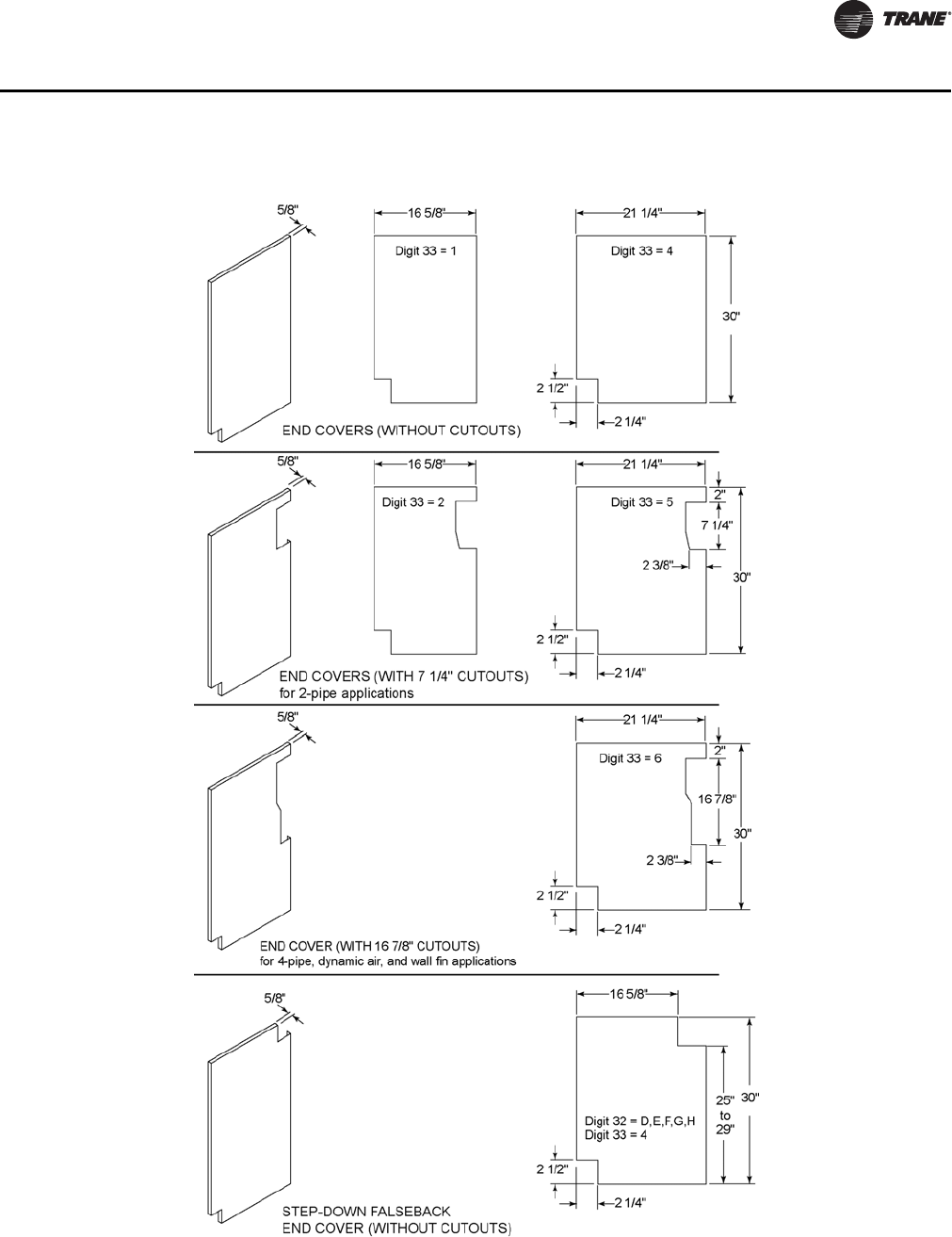
UV-PRC003-EN 85
Dimensional Data
End Covers
UV-PRC003-EN.book Page 85 Tuesday, June 4, 2013 8:59 PM
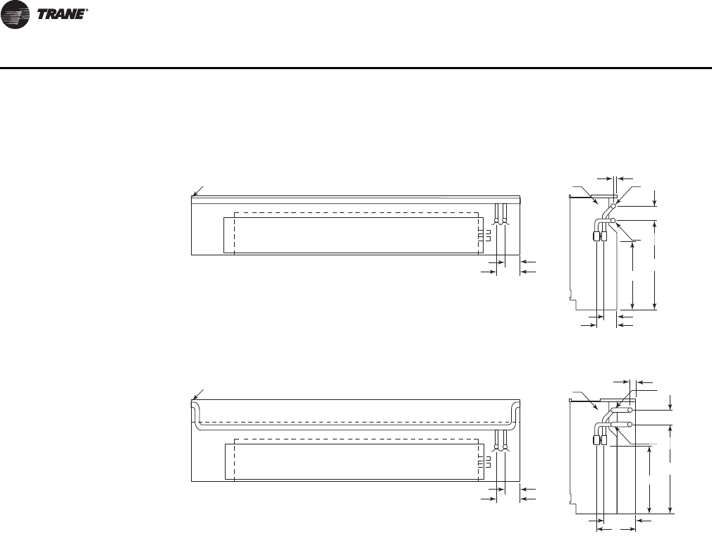
86 UV-PRC003-EN
Dimensional Data
Note: 1-3/8 in. OD and 2-1/8 in. OD crossover piping
•Crossover piping is available for all 2- or 4-pipe coils selections. Trane provides the crossover
for the hot water only. The crossover pipe is factory-insulated with 3/8 in.-thick insulation.
•Expansion compensation between the factory piping package and the crossover piping is
achieved using a flex hose rated at 250 psi working pressure. Flex hose is only available with
factory-mounted piping packages.
•Expansion compensation for the crossover piping must be handled external to the unit
ventilator.
•Crossover connections terminate in the same end pocket as the heating coil on all 2- and 4-pipe
coils.
FLUSH
FLUSH
1 1/2"
1 1/4"
3"
24"
19 3/8"
3 5/8"
5 3/8"
RETURN
7/8" I.D. FIELD
CONN. W/ SHUT
OFF VALVE
7/8" I.D. FIELD
CONN. W/ SHUT
OFF VALVE RETURN
TOP VIEW
SIDE VIEW
TOP VIEW
SIDE VIEW
16 5/8" DEPTH UNIT
21 1/4" DEPTH UNIT
SUPPLY
3"
24"
19 3/8"
3 1/2"
4 1/2"
8 1/4"
10"
SUPPLY
RS
3 1/2"
4 1/2"
RS
Crossover Piping
UV-PRC003-EN.book Page 86 Tuesday, June 4, 2013 8:59 PM

UV-PRC003-EN 87
Mechanical Specifications
General
Deliver and install a complete unit ventilator certified for ventilation at AHRI-840, or tested by an
independent testing and balancing lab witnessed by owner’s representative.
Safety
All standard units are UL-listed in the United States and Canada and comply with NFPA 90A
requirements.
The unit ventilator is certified or rated in accordance to the following listings for performance proof
and safety: ETL, AHRI-840, AHRI-350, LONMARK®, BACnet®
Equipment Construction
Exterior cabinetry is constructed of heavy-gauge metal for strength and durability. All exposed
edges shall be rounded to safeguard against injury. All interior sheet metal shall be of galvanized
steel to restrain against deterioration.
The front plane of the unit consists of a three panel design. The control compartment is accessible
without removing the entire front panel. The discharge air grille contains rounded edged steel bars,
and are placed at a 15° slope to provide proper airflow deflection.
Access for inspection and cleaning of the unit drain pan, coils, and fan section is provided. The unit
shall be installed for proper access. Procedures for proper maintenance of the unit shall is included
in the installing, operation manual.
Cabinet insulation is closed cell to maximize thermal performance. It is suitable for use in air
streams up to 4500 feet per minute (fpm). Insulation will meet the Underwriters Laboratories Fire
Hazard Classification and long term thermal resistance (LTTR) classification per CAN/ULC S770
standard.
Piping and control end pockets are a minimum of 12 inches wide to facilitate piping, auxiliary drain
pan, and service access.
Final finish of the cabinet is cleaned, phosphatized and painted with an electrostatic powder spray
system, with a minimum thickness of 1.5 mil to avoid visible runs and resist abrasion.
Unit Fans
The unit fan board assembly shall ship from the factory wired to the commission schedule for
engineered cfm expectancy. A motor speed switch is on the unit or wall for motor speed
adjustment.
The fan board is a single, rigid construction, made from corrosion resistive material. It is a trouble-
free slide design to provide cleaning and serviceability ease to maintenance personnel.
The fans contain a double width/double inlet, forward curved centrifugal design to sustain
appropriate air throw into the space. The wheels are galvanized metal to resist corrosion. The
dynamically balanced fan and motor are of direct drive style.
The fan and coil arrangement are of a blow-thru configuration to supply unvarying coil face velocity
avoiding cold spots on the coil.
Motors
All motors are brushless DC (BLDC)/electronically commutated motors (ECM) factory-
programmed and run-tested in assembled units. The motor controller is mounted in a touch-safe
control box with a built-in integrated user interface and LED tachometer. If adjustments are needed,
motor parameters can be adjusted through momentary contact switches accessible without
factory service personnel on the motor control board. Motors will soft-ramp between speeds to
lessen the acoustics due to sudden speed changes. Motors can be operated at three speeds or with
a field-supplied variable speed controller. The motor will choose the highest speed if there are
simultaneous/conflicting speed requests. All motors have integral thermal overload protection
UV-PRC003-EN.book Page 87 Tuesday, June 4, 2013 8:59 PM

88 UV-PRC003-EN
Mechanical Specifications
with a maximum ambient operating temperature of 104°F and are permanently lubricated. Motors
are capable of starting at 50 percent of rated voltage and operating at 90 percent of rated voltage
on all speed settings. Motors can operate up to 10 percent over voltage.
Drain Pan(s)
The unit drain pan consists of a corrosion resistant, environmentally friendly, dual sloped design
to facilitate condensate removal quickly. The pan is removable for cleaning. Hook-up to the drain
pan for condensate removal is made on the cooling coil union side. The drain side connection shall
be easily field-inverted by removing and rotating the pan 180°.
An auxiliary drain pan (optional accessory) is factory-provided, and field-installed under the main,
cooling piping package. It is constructed of the same corrosion resistance material found in the
main unit drain pan. The auxiliary pan will effortlessly fit into the end pocket for condensate
disposal of the piping package.
Hydronic Coils (option)
All hydronic coils are a plate-fin type, mechanically bonded to tubes. The coils are hydrostatically
tested to 350 psig and burst tested to 450 psig. The coils are rated in accordance with AHRI-840.
A threaded drain plug is provided at the header’s lowest point, and a manual air vent provided at
its highest point.
The standard 4-pipe heating coil is placed in the preheat location. Optional 4-pipe heating coils are
available in the reheat position for dehumidification control.
Refrigerant Coils (option)
Direct expansion coils contain copper tubes mechanically expanded into evenly spaced aluminum
fins. All coils are proof and leak tested before leaving the manufacturer. The proof test is performed
at 1.5 times the maximum operating pressure, and leak tested at the maximum operating pressure.
In addition, the tubes are completely evacuated of air to check for leaks in the vacuum.
The refrigerant coil distributor assemblies is Venturi or orifice style with round copper distributor
tubes.
Distributors are sized consistently with capacity of coil. Suction headers are fabricated from round
copper pipe.
A thermostatic expansion valve (TXV) is factory selected and installed for a wide-range of control
to maintain optimum control of superheat. All coils are shipped with a dry nitrogen holding charge.
Electric Coil (option)
Units equipped for electric heat contain a special resistance, heating element design inserted in an
extended surface fin-tube bundle for maximum element life and safety. Units specifying electric
heat include (as standard) a high temperature cut out with a continuous sensing element. This
device interrupts electrical power whenever excessive temperatures are sensed anywhere along
the leaving side of the coil. A contactor (also provided) ensure positive disconnect of electrical
power whenever the fan motor power is interrupted. All electric heat units have a power wiring
console in the right hand end-pocket to better facilitate field wiring of the unit.
Steam Coil (option)
Units including a steam coil are of a 5/8-inch, sigma-flow, tube-in-tube, distributing coil design.
Steam coil tubing is mechanically expanded into evenly spaced aluminum fins. The supply and
return connections are on the same side, and include a 1-inch female pipe thread (FPT) termination.
The coil is pitched by the manufacturer to provide condensate drainage for freeze protection.
Outside Air/Return Air Damper
Each unit ventilator is equipped with a linkage free, air-tight damper design. This linkage free
design results in a fixed air seal of the damper assembly.
UV-PRC003-EN.book Page 88 Tuesday, June 4, 2013 8:59 PM

UV-PRC003-EN 89
Mechanical Specifications
Face and Bypass Damper (option)
The face and bypass damper control is utilized for economizing and dehumidification of the
equipment during seasonal or morning warm-up. The damper is constructed of aluminum grade
metal. The damper is tightly sealed and designed to minimize heat pickup in the bypass position.
Controls
Controls options are: unit-mounted fan speed switch, customer supplied terminal interface (CSTI),
Tracer ZN520, and Tracer UC400. A variety of inputs and outputs are available for the CSTI and
Tracer controller options. A disconnect switch (for non-electric heat units), fused transformer,
contactor(s), and terminal strip are provided with the CSTI and Tracer controller options.
Customer Supplied Terminal Interface (CSTI)
The control interface is intended to be used with a field-supplied, low-voltage thermostat or
controller. The control box contains a relay board which includes a line voltage to 24-volt
transformer, and an optional disconnect switch. All end devices are wired to a low-voltage terminal
block and are run-tested, so the only a power connection and thermostat/controller connection is
needed to commission the unit. Changeover sensors and controls are provided whenever a
change-over coil is selected. When N.O. valves are selected, inverting relays are provided for use
with standard thermostats.
Unit-mounted Fan Speed Switch (FSS)
The fan speed switch is available with or without the control interface option. The unit-mounted
FSS will employ a low-voltage fan switch. The low-voltage fan speed option will provide an
interface to factory wiring, including variable speed/high-medium-low (HML) control. The control
box contains a line voltage to 24-volt transformer, EC motor controller, and an optional disconnect
switch.
Tracer ZN520
The Tracer ZN520 discrete speed controller can be used in a stand-alone application or used as part
of a Trane Integrated Comfort System (ICS) with LonTalk® communication. The Tracer ZN520 offers
the combined advantages of simple and dependable operation. Standard control features include
options normally available on more elaborate control systems. All control options are available
factory-mounted, -wired, and -configured and can also be field-configured using a service tool.
Tracer UC400
The Tracer UC400 controller delivers single zone VAV control in a stand-alone application or as part
of a Trane Integrated Comfort system with BACnet® communication. The Trace UC400 offers the
combined advantages of a factory-mounted, -wired, and -programmed controller for dependable
out-of-the box operation. Standard control features include options normally available on more
elaborate control systems. All control options are available factory-programmed with additional
configuration and programming in the field using a service tool.
Zone Sensors (option)
Trane offers a full line of wired and wireless temperature sensors. Wired temperature sensors are
the suitable alternative for locations that cannot accommodate wireless sensors or that require a
service tool connection. Wireless temperature sensors, which provide easy and flexible
installation, are a cost-effective alternative to wired sensors.
Some additional options available with the sensors include:
• Easy-to-use display interface for clear and simple monitoring and control.
• Temperature setpoint control to allow the tenant to choose a temperature setpoint that satisfies
their personal preference.
• Fan speed switch to allow the tenant to locally control the fan speed to better satisfy their
preference.
UV-PRC003-EN.book Page 89 Tuesday, June 4, 2013 8:59 PM

90 UV-PRC003-EN
Mechanical Specifications
• Occupancy override to allow the tenant to request temporary timed override system operation
that keeps the building conditions in occupied comfort conditions.
• COMM module that is compatible with all Trane® wired temperature sensors. This accessory
provides a local RJ22 connection to Trane® service tools for easy, low-cost maintenance.
Filter
Units equipped with a standard throwaway filter have an average resistance of 76 percent and dust
holding capacity of 26 grams per square foot.
Units equipped with 1-in. MERV 8 filters have a rating based on ASHRAE Standard 52.2. The
average dust spot efficiency is no less than 35 to 40 percent when tested in accordance with
ASHRAE Standard 52.1 atmospheric dust spot method.
Units equipped with 1-in. MERV 13 filters have a rating based on ASHRAE Standard 52.2. The
average dust spot efficiency is no less than 90 percent efficiency on 1–3 micron particles and
greater than 90 percent efficiency on 3–10 micron particles when tested in accordance with
ASHRAE Test Standard 52.2.
UV-PRC003-EN.book Page 90 Tuesday, June 4, 2013 8:59 PM

Trane optimizes the performance of homes and buildings around the world. A business of Ingersoll Rand, the
leader in creating and sustaining safe, comfortable and energy efficient environments, Trane offers a broad
portfolio of advanced controls and HVAC systems, comprehensive building services, and parts.
For more information, visit www.Trane.com.
Trane has a policy of continuous product and product data improvement and reserves the right to change design and specifications without notice.
We are committed to using environmentally
conscious print practices that reduce waste.
© 2013 Trane All rights reserved
UV-PRC003-EN 04 Jun 2013
Supersedes UV-PRC003-EN (20 Dec 2012)
UV-PRC003-EN.book Page 91 Tuesday, June 4, 2013 8:59 PM
