Trane Wphf Users Manual WSHP SVX04A EN
WPHF to the manual 58b3a16f-08d9-4dc2-8a27-3297c531fdac
2015-01-29
: Trane Trane-Wphf-Users-Manual-236215 trane-wphf-users-manual-236215 trane pdf
Open the PDF directly: View PDF ![]() .
.
Page Count: 39
WSHP-SVX04A-EN
Models
“A” and later Design Sequence
Installation
Owner
Diagnostics
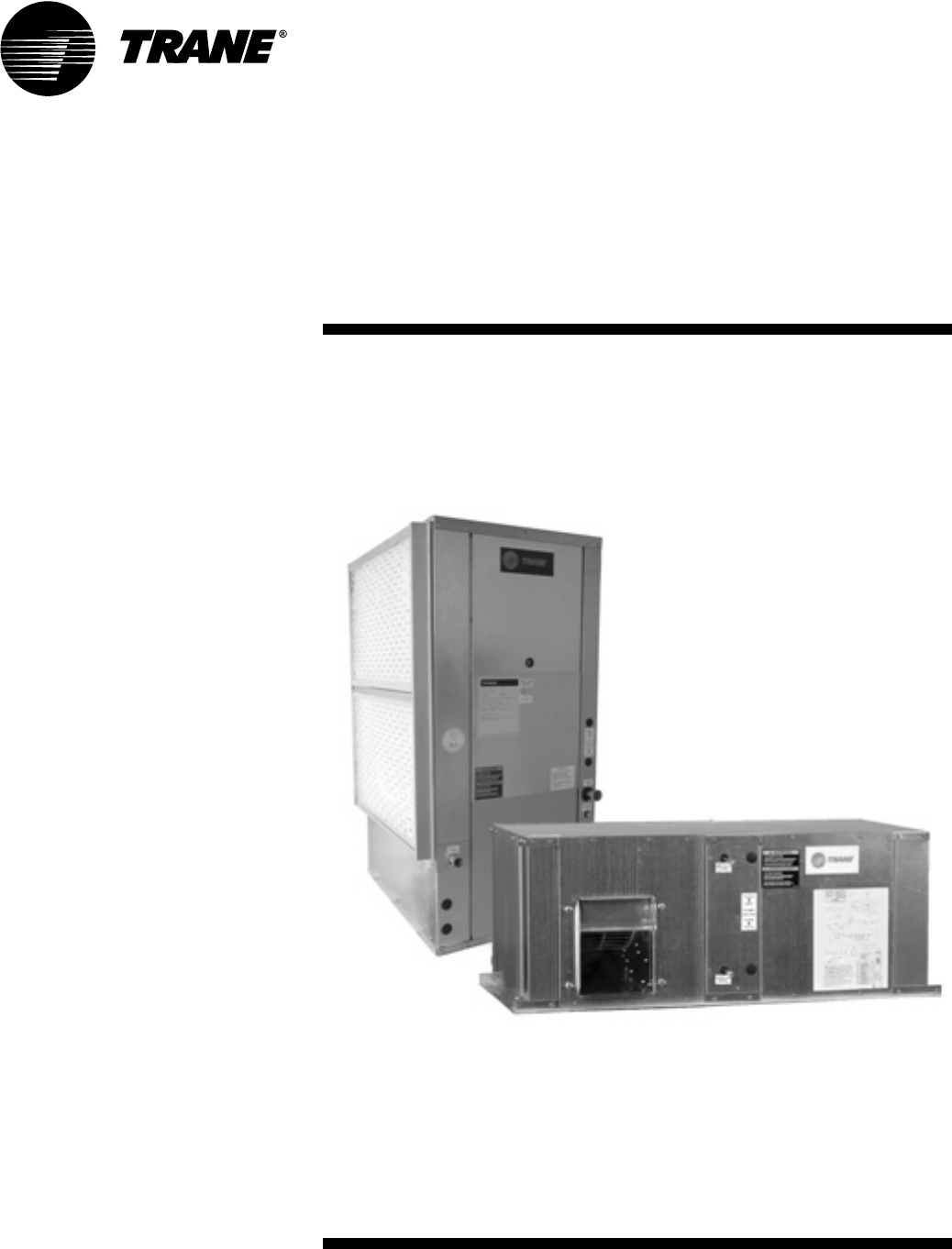
Extra High Efficiency
Water-Source Heat Pump
Models WPVJ and WPHF
WPVJ
018-072 – 60 HZ
WPHF
021-057 – 60 HZ
© 2003 American Standard Inc. All rights reserved. WSHP-SVX04A-EN
Notice
NOTICE:
Warnings and Cautions appear at appropriate sections throughout this manual.
Read these carefully.
WARNING -Indicates a potentially hazardous situation which, if
not avoided, could result in death or serious injury.
CAUTION -Indicates a potentially hazardous situation which, if not
avoided, may result in minor or moderate injury. It
may also be used to alert against unsafe practices.
CAUTION -Indicates a situation that may result in equipment or
property-damage-only accidents.
NOTICE:
Unit contains HCFC (R-22) Refrigerant
Instructions!
Section 608, Paragraph C of the 1990 Clean Air Act states:
Effective July 1, 1992, it shall be unlawful for any person, in course of
maintaining, servicing, repairing, or disposing of an air conditioning system, to
knowingly vent or release any CFC or HCFC refrigerant. Minimal releases (air
purges or refrigerant hoses) associated with good faith attempts to recapture or
recycle are exempt from the ban on venting.
Responsible Refrigerant Practices!
Trane believes that responsible refrigerant practices are important to the
environment, our customers, and the air conditioning industry. All technicians
who handle refrigerants must be certified. The Federal Clean Air Act (Section 608)
sets forth the requirements for handling, reclaiming, recovering and recycling of
certain refrigerants and the equipment that is used in these service procedures.
In addition, some states or municipalities may have additional requirements that
must also be adhered to for responsible management of refrigerants. Know the
applicable laws and follow them.
Important!
Equipment is shipped FOB (Free on
Board) at the manufacturer. Therefore,
freight claims for damages against the
carrier must be initiated by the receiver.
WSHP-SVX04A-EN 3
Contents
Installation/Startup/Commissioning
4
Pre-installation Checklist 4
General Information 5
Dimensions/Weights 6
Installation Instructions 14
Electrical Requirements 20
Pre-Startup Checklist 25
Startup/Commissioning
26
Sequence of Operation 26
Operating Pressures 27
30
Startup Checklist & Log 30
Maintenance
31
Warranty Information
32
Troubleshooting Checklist
33
Unit Wiring
35
4WSHP-SVX04A-EN
WARNING
Fiberglass Wool!
Product contains fiberglass wool. Disturbing the insulation in this
product during installation, maintenance or repair will expose you to
airborne particles of glass wool fibers and ceramic fibers known to the
state of California to cause cancer through inhalation. Glass wool fibers
may also cause respiratory, skin or eye irritation.
Jobsite Inspection
Always perform the following checks before accepting a unit:
1. Verify that the nameplate data matches the data on the sales order and bill of
lading (including electrical data).
2. Verify that the power supply complies with the unit nameplate specifications.
3. Visually inspect the exterior of the unit, for signs of shipping damage. Do not
sign the bill of lading accepting the unit(s) until inspection has been com-
pleted. Check for damage promptly after the unit(s) are unloaded. Once the
bill of lading is signed at the jobsite, the unit(s) are now the property of the
SOLD TO party and future freight claims MAY NOT be accepted by the freight
company.
4. Verify that the refrigerant charge has been retained during shipment by use
of gauges. Schrader taps are located external to the cabinet on the 1 1/2-ton
through 6-ton equipment.
5. After assuring that charge has been retained, reinstall the schrader caps to
assure that refrigerant leakage does not occur.
WARNING
Microbial Growth!
Wet interior unit insulation can become an amplification site for
microbial growth (mold), which may cause odors and damage to the
equipment and building materials. If there is evidence of microbial
growth (mold) on the interior insulation, the insulation should be
removed and replaced prior to operating the system.
Jobsite Storage
This unit is intended for indoor use only. To protect the unit from damage due to
the elements, and to prevent possible IAQ contaminant sources from growing,
the unit should be stored indoors. If indoor storage is not possible, the following
provisions for outdoor storage must be met:
1. Place the unit(s) on a dry surface or raise above the ground to assure ade-
quate air circulation beneath the unit.
2. Cover the unit(s) with a water proof tarp to protect them from the elements.
3. Make provisions for continuous venting of the covered units to prevent
moisture from standing on the unit(s) surfaces. Wet interior unit insulation
can become an amplification site for microbial growth (mold) which has
been determined to be a cause of odors and serious health related indoor air
quality problems.
4. Store refrigeration units units in the normal UP orientation to maintain oil in
the compressor.
5. Model WPHF units should not be stacked more than three high. Do not stack
WPVJ units.
Pre-installation
Checklist
WSHP-SVX04A-EN 5
General
Information
Unit Nameplate
The unit nameplate is located at the
front of the unit. It includes the unit
model number, serial number, electri-
cal characteristics, refrigerant charge,
and other pertinent unit data.
Compressor Nameplate
The nameplate for the compressors
are located on the compressor shell.
Unit Description
Before shipment, each unit is leak test-
ed, dehydrated, charged with refriger-
ant and run tested for proper control
operation.
Water-to-Refrigerant Coils
The co-axial water-to-refrigerant heat
exchanger for the 1 1/2-ton through 6-
ton equipment is constructed of cop-
per or cupro-nickel (option) for the wa-
ter section and stainless steel for the
refrigeration section.
The heat exchanger is leak tested to
assure there is no cross leakage be-
tween the water and refrigerant gas.
Water Connections
Water connections are located at the
unit front for both the WPVJ and
WPHF units. They are clearly labled for
supply/return connection. Sizes are as
follows.
Blower/Motor
The blower and motor is located inside
the unit cabinet. The motor may be
easily removed for service through the
equipment blower access panel.
Controls
The control system offered to control
the unit is a Basic 24 volt control, Basic
24 volt control, or TracerTM ZN510
control. A 50 VA transformer is factory
supplied on the Basic 24V control con-
figurations. A 75 VA transformer is fac-
Dia. Type
3/4" WPHF 021-027 - Water in/out
1" WPHF 030-072 - Water in/out
1" WPVJ - Water in/out
3/4" Drain
1/2" Desuperheater
tory supplied on the ZN510 (digital)
control configurations.
ZN510 Controls
(WPVJ and WPHF option)
Units incorporating the ZN510 control
option design will include a digital
LonTalkTM certified control board. The
control board will support such op-
tions as: random start delay, heating/
cooling status, occupied/unoccupied
mode and fan/filter status.
Power wiring is made at the contactor.
See manual WSHP-IOP-2 for diagnos-
tic information.
Schrader Connections
Connections for the low and high side
of the refrigeration system are located
conveniently at the equipments front
panel. Sheet metal removal is not re-
quired for positive connection to the
high and low schrader connections.
6WSHP-SVX04A-EN
Table 1: Unit weights
Size
Shipping
Weight
with pallet (lb)
Shipping
Weight
w/o pallet (lb)
WPVJ
018 249 239
024 250 240
030 298 288
036 315 305
042 324 314
048 398 388
060 439 429
072 440 430
WPHF
021, 027 279 267
035. 040 367 356
047, 057 433 403
WARNING
Improper Unit Lift!
Test lift unit approximately 24 inches to verify proper
center of gravity lift point. To avoid dropping of unit,
reposition lifting point if unit is not level. Failure to
properly lift unit could result in death or serious injury
or possible equipment or property-only damage.
Dimensions/Weights/
Clearance
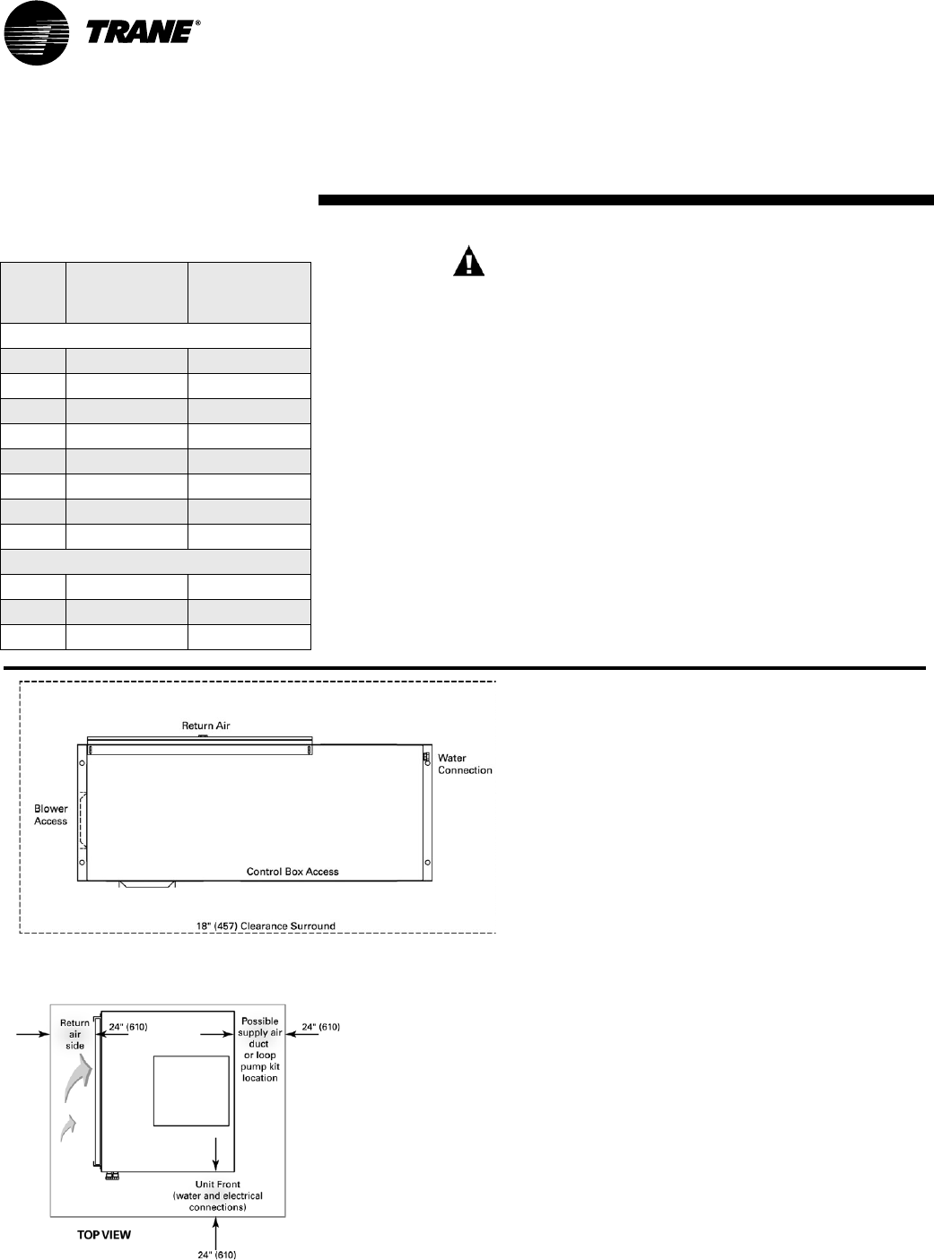
Figure 2: Mechanical clearances - WPVJ
Unit Location and Clearances
Locate the unit in an indoor area. The
ambient temperature surrounding the
unit must not be less than 45°F. Do not
locate the unit in areas subject to
freezing.
Attention should be given to service
clearance and technician safety. The
unit should be easily maintained or
serviced in all applications. There
must be enough space for service per-
sonnel to perform maintenance or re-
pair. Provide sufficient room to make
water, and electrical connection(s). Lo-
cal and national codes should be fol-
lowed in providing electrical power
connections. See Figure 1 and 2 for
mechanical clearances.
Figure 1: Mechanical clearances - WPHF
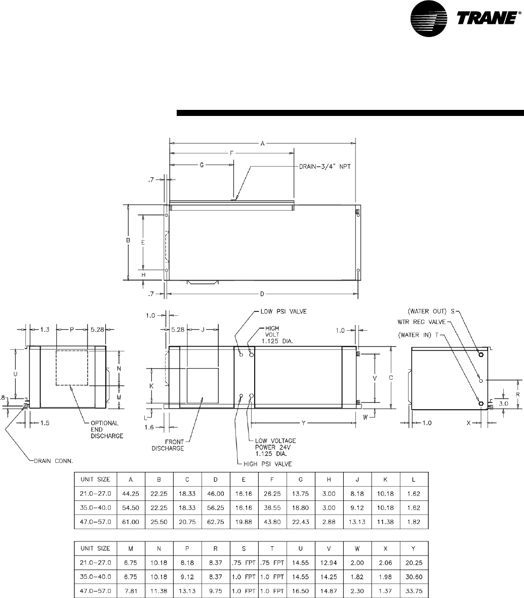
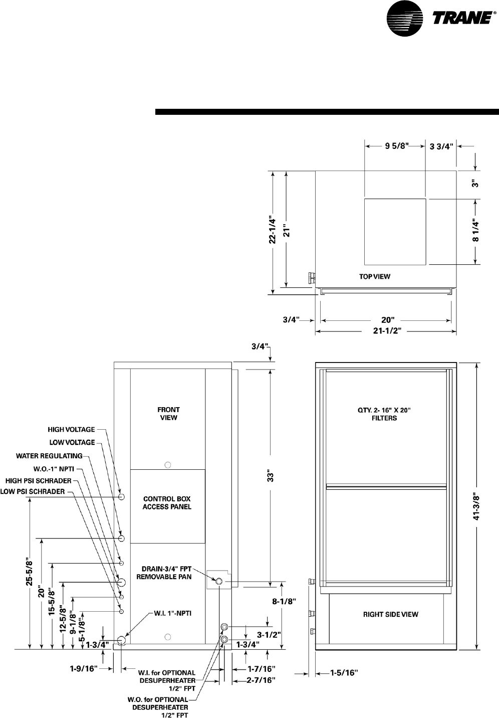
WSHP-SVX04A-EN 7
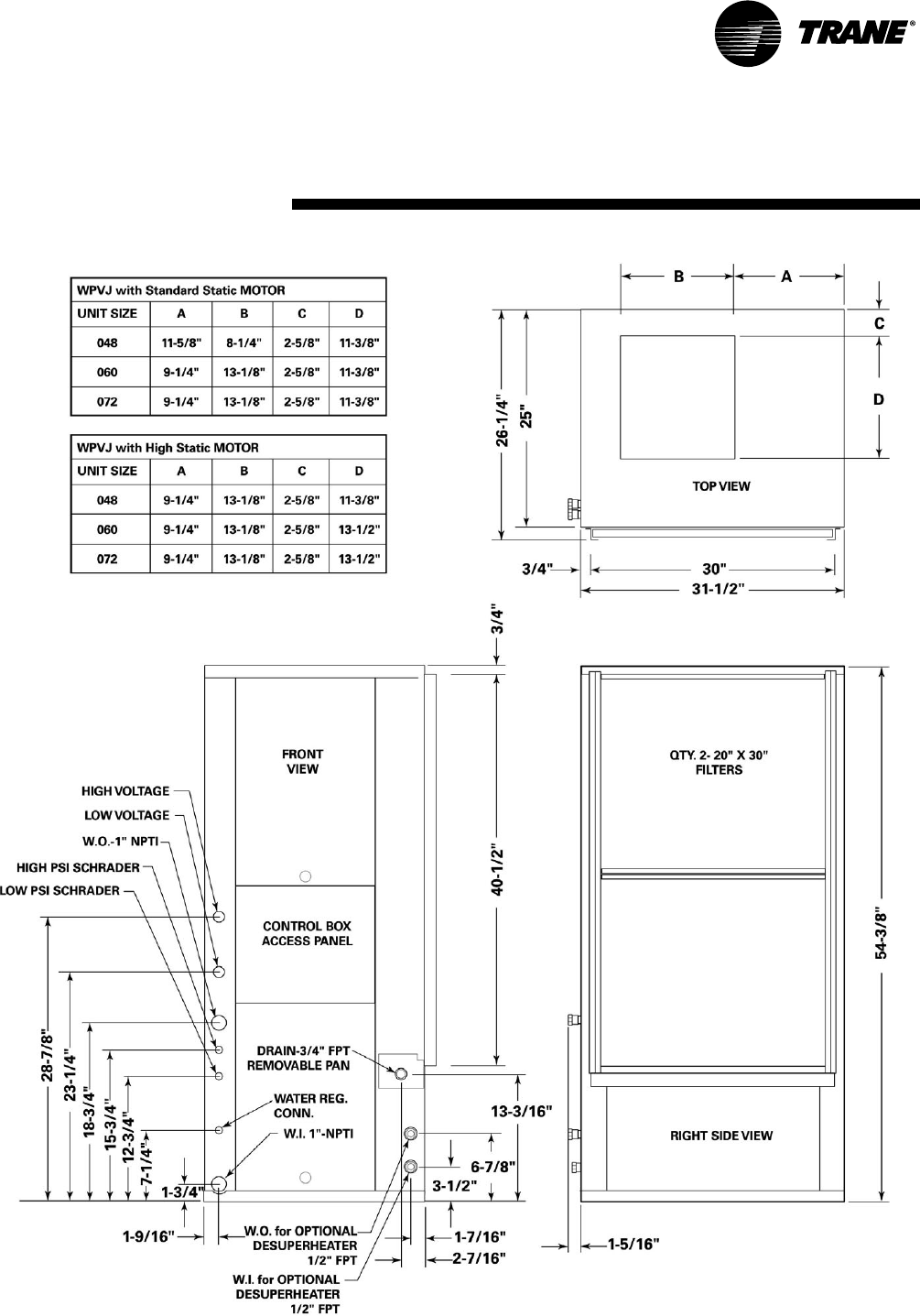
Dimensions
WPHF 021-057
8WSHP-SVX04A-EN
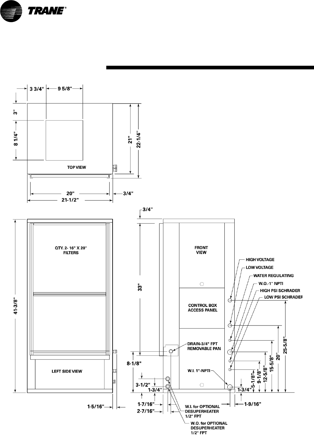
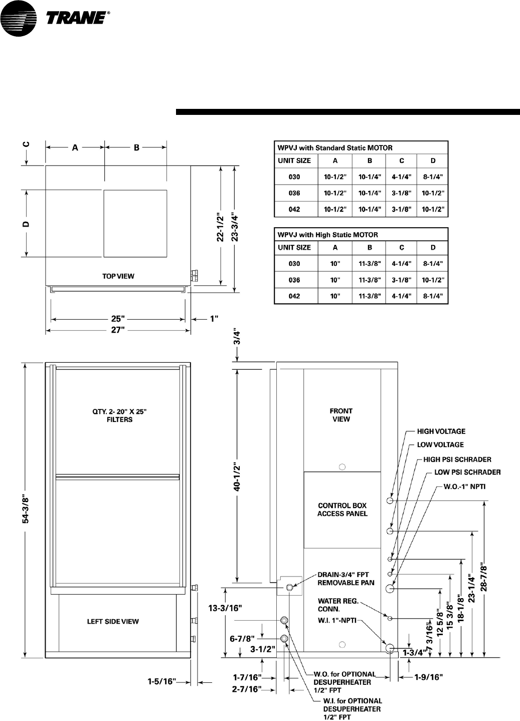
Dimensions
WPVJ 018-024 LH
WSHP-SVX04A-EN 9
Dimensions
WPVJ 018-024 RH
10 WSHP-SVX04A-EN
Dimensions
WPVJ 030-042 LH
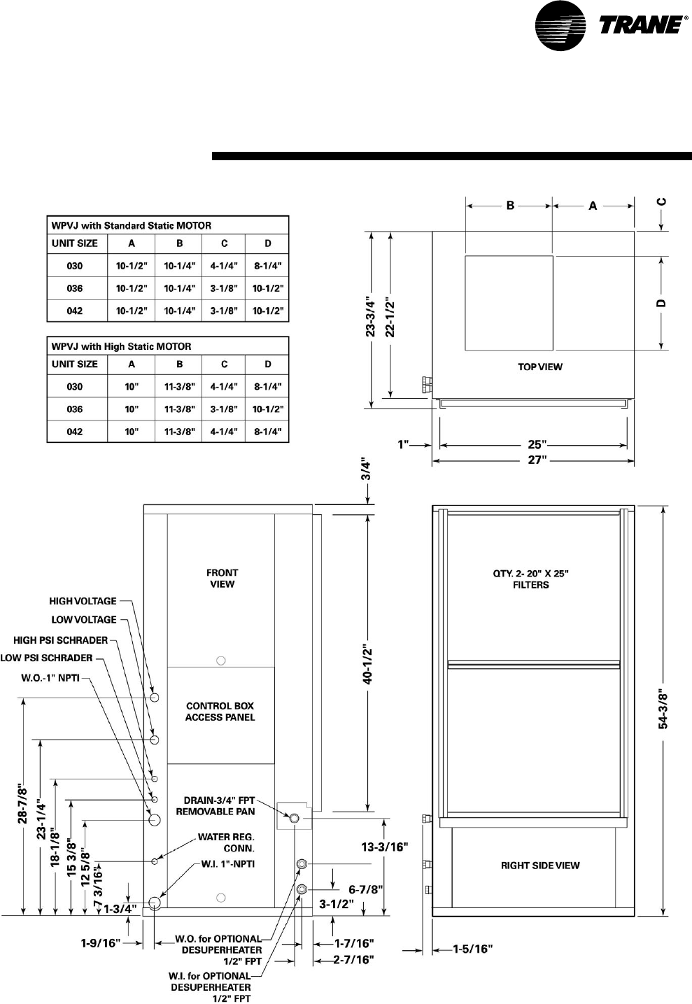
WSHP-SVX04A-EN 11
Dimensions
WPVJ 030-042 RH
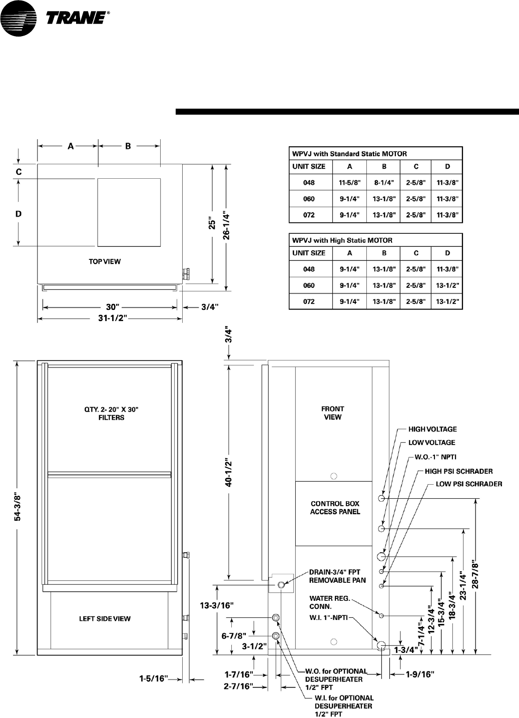
12 WSHP-SVX04A-EN
Dimensions
WPVJ 048-072 LH
WSHP-SVX04A-EN 13
Dimensions
WPVJ 048-072 RH

14 WSHP-SVX04A-EN
General Installation Checks
The checklist below is a summary of
the steps required to successfully in-
stall a unit. This checklist is intended to
acquaint the installing personnel with
procedures required in the installation
process. It does not replace the de-
tailed instructions called out in the ap-
plicable sections of this manual.
1 Remove packaging and inspect the
unit. Check the unit for shipping
damage and material shortage; file
a freight claim and notify appropri-
ate sales representation.
Note: The vertical units have been
tied to the skid by (8) shipping
brackets with (16) 5/16" screws.
Remove the (8) screws attached on
the unit side, and (2) screws at-
tached at the L bracket side. The
unit may now be slid off of the
skid. Re-attach (8) of the screws
into the unit base pan.
2 Verify the correct model, options
and voltage from the unit name-
plate.
3 Verify the installation location of
the unit will provide the required
clearance for proper operation.
4 Remove refrigeration access panel
and inspect the unit. Be certain the
refrigerant tubing has clearance
from adjacent parts.
WARNING
Hazardous
Voltage!
Disconnect all electric power,
including remote disconnects
before servicing. Follow proper
lockout/tagout procedures to
ensure the power can not be
inadvertently energized. Failure to
disconnect power before
servicing could result in death or
serious injury.
Main Electrical
5 Verify the power supply complies
with the unit nameplate specifica-
tions.
6 Inspect all control panel compo-
nents; tighten any loose connec-
tions.
7 Connect properly sized and pro-
tected power supply wiring to a
field-supplied/installed disconnect
switch and to the unit contactor
(1K1) in the unit’s cabinet control
box for equipment.
8 Install proper grounding wires to
an earth ground.
Note: All field-installed wiring must
comply with NEC and applicable local
codes.
Low Voltage Wiring (AC & DC)
Requirements
9 Connect properly sized control wir-
ing to the proper termination
points between the thermostat/
sensor and the terminal board in
the unit’s control box.
Filter Installation
10 Each unit ships with 1" filters. Do
not operate the unit without fil-
ters.
Installation
WSHP-SVX04A-EN 15
Unit Installation; WPVJ
Duct collars are provided for the WPVJ
equipment. The duct system and dif-
fusers should be sized inaccordance
with ASHRAE or ACCA Manual D.
1 Install a flexible connector (field
provided) for supply/return air duct
connections on all metal duct sys-
tems.
Note: If the unit is connected to ex-
isting ductwork, an initial check of
the mechanical system should be
made to insure the duct has the ca-
pacity to handle the air required for
the unit application. If ducting is too
small, as in the replacement of heat-
ing only systems, larger ductwork
should be installed. All existing
ductwork should be checked for
leaks, and repairs should be made.
2 Insulate the field ductwork with a
minimum of 1" duct insulation.
Note: Installing the unit to an unin-
sulated ductwork in an uncondi-
tioned space may adversely affect
the unit’s performance, as well as in-
crease noise emissions into the
space.
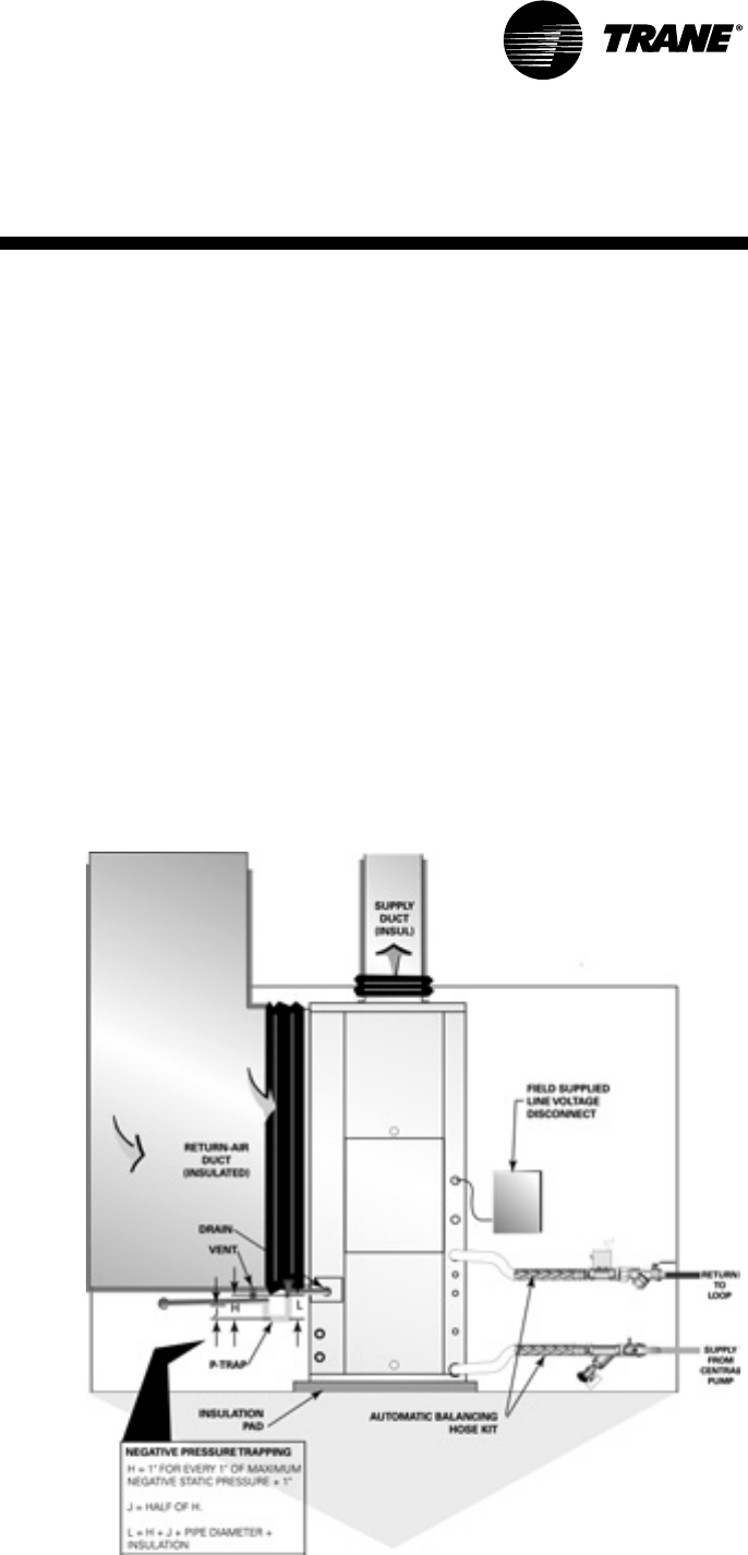
3 Install proper condensate trapping
to the equipment. The unit drain
connection is 3/4" (19mm). When de-
signing the condensate trap, it is im-
portant to consider the unit’s draw-
thru design requiring negative pres-
sure trapping.
In a properly trapping system, when
condensate forms during normal
operation, the water level in the trap
rises until there is a constant flow
(Figure 3). It is imperative to main-
tain water in the trap and not allow
the trap to dry out during heating
season. Keeping the trap primed at
all times will enable the water to
flow properly.
Condensate piping must be installed
to allow the cleanable condensate
pan to be removed for cleaning.
Minimum clearances for drain pan
removal are 22" (sizes 018 and 024),
25" (sizes 030 and 042), and 27" (siz-
es 048 through 072).
4 Flush System. See page 17 for sys-
tem flushing.
Water Connection
For vibration isolation, it is recom-
mended that flexible steel braided
hoses be installed instead of hard pip-
ing between the supply/return risers
and the equipment.
Trane offers 4-types of hose kit varia-
tions:
• Stainless steel braided flexible
hose with manual shut-off (ball)
valves
• Stainless steel braided flexible
hose with manual deluxe shut-off
(ball) valves
• Stainless steel braided flexible
hose with manual circuit-setter
valve
• Stainless steel braided flexible
hose with automatic balancing
valve
Additional accessories, such as a
strainer are recommended for use to
eliminate contaminants from entering
the co-axial water-to-refrigerant heat
exchangers.
Installation
Figure 3: Negative pressure trap
16 WSHP-SVX04A-EN
Unit Installation; WPHF
Duct collars are provided for the WPHF
equipment. The duct system and dif-
fusers should be sized inaccordance
with ASHRAE or ACCA Manual D.
1 Install a flexible connector (field
provided) for supply/return air duct
connections on all metal duct sys-
tems.
Note: If the unit is connected to ex-
isting ductwork, an initial check of
the mechanical system should be
made to insure the duct has the ca-
pacity to handle the air required for
the unit application. If ducting is too
small, as in the replacement of heat-
ing only systems, larger ductwork
should be installed. All existing
ductwork should be checked for
leaks, and repairs should be made.
2 Insulate the field ductwork with a
minimum of 1" duct insulation.
Note: Installing the unit to an unin-
sulated ductwork in an uncondi-
tioned space may adversely affect
the unit’s performance, as well as in-
crease noise emissions into the
space.
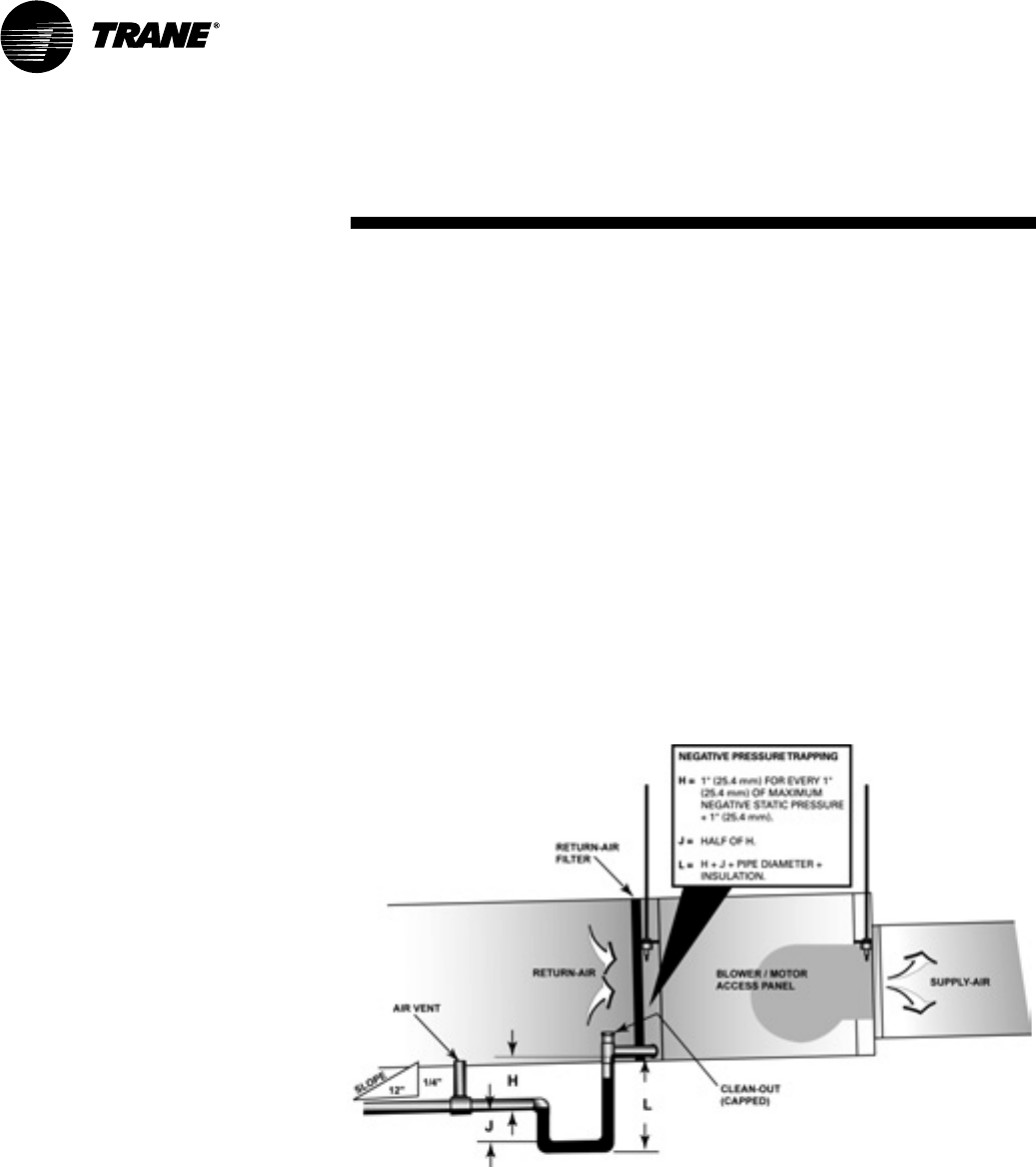
3 Install proper condensate trapping
to the equipment. The unit drain
connection is 3/4" (19mm). When de-
signing the condensate trap, it is im-
portant to consider the unit’s draw-
thru design requiring negative pres-
sure trapping.
In a properly trapping system, when
condensate forms during normal
operation, the water level in the trap
rises until there is a constant flow
(Figure 4). It is imperative to main-
tain water in the trap and not allow
the trap to dry out during heating
season. Keeping the trap primed at
all times will enable the water to
flow properly.
Condensate piping must be installed
to allow the cleanable condensate
pan to be removed for cleaning.
4 Flush System. See page 17 for sys-
tem flushing.
Water Connection
For vibration isolation, it is recom-
mended that flexible steel braided
hoses be installed instead of hard pip-
ing between the supply/return risers
and the equipment.
Trane offers 4-types of hose kit varia-
tions:
• Stainless steel braided flexible
hose with manual shut-off (ball)
valves
• Stainless steel braided flexible
hose with manual deluxe shut-off
(ball) valves
• Stainless steel braided flexible
hose with manual circuit-setter
valve
• Stainless steel braided flexible
hose with automatic balancing
valve
Additional accessories, such as a
strainer are recommended for use to
eliminate contaminants from entering
the co-axial water-to-refrigerant heat
exchangers.
Installation
Figure 4: Negative pressure trap
WSHP-SVX04A-EN 17
Connecting a Distributed Pump
Kit to a Closed Loop System
All piping external to the unit is the re-
sponsibility of the installer. The water
pipe installation must be done in ac-
cordance with local codes. If no local
code applies, national codes should be
followed. It is the contractor’s respon-
sibility to know and adhere to all appli-
cable codes.
Water inlet and outlet to the unit’s wa-
ter-to-refrigerant heat exchanger are
clearly marked on the submittal draw-
ings found on pages 7 through 13. The
supply and return piping must be in-
stalled correctly to the unit to ensure
the safety devices will work properly.
Units that are not piped accordingly
will not obtain the manufacturers war-
ranty.
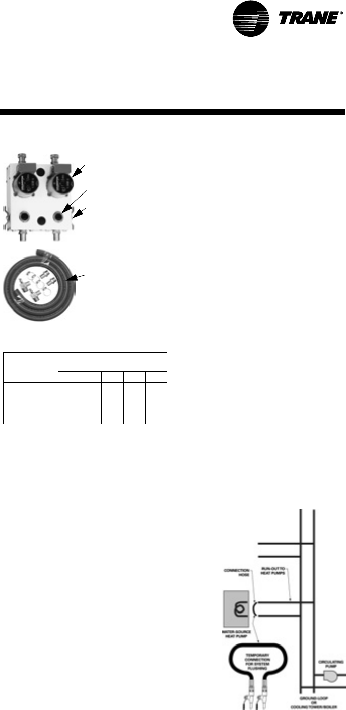
A pump module and hose kit (Figure 5)
may be used to connect the unit to
closed loop piping.
Using Antifreeze
In areas of the country where entering
water temperatures drop below 45°F
or where piping is being run through
areas subject to freezing, the loop
must be freeze protected by using an
approved antifreeze solution to pre-
vent the earth loop water from freez-
ing inside the heat exchanger.
Methanol, Ethylene, and Propylene
Glycol are the most commonly used
antifreeze solutions. Consult your geo-
thermal unit supplier for the best solu-
tions in your area.
Propylene glycol is not recommended
in installations where the water tem-
perature are expected to fall below
30°F. At extreme temperatures, the vis-
cosity increases to the point where
normal loop circulating pumps cannot
maintain proper flow.
Calculate the approximate volume of
water in the system by using the re-
quirements detailed in Table 2. Add
three gallons to this total to allow for
the water contained in the hose kit and
geothermal unit.
Table 2: Required Antifreeze by volume
Cleaning and Flushing
the Water Loop
After the piping system is complete,
cleaning and flushing the water loop
should be done to avoid trash settle-
out in the condenser (Figure 6). An ex-
tra pipe may be necessary to connect
the hose kits.
1 Electrical power to the unit should
be disconnected.
2 Double back the supply hose and
connect directly to the return riser
valve.
3 Fill the water system with clean wa-
ter using the water make up connec-
tions. Note: Air vents should be
opened during filling.
4 With the air vents closed, start the
circulating pump and then crack the air
vents to bleed off the trapped air, as-
suring circulation through all compo-
nents of the system. Note: Make up
water must be available to the system
to replace the volume formerly occu-
pied by the air that is bled off.
Type of
Antifreeze
Minimum Temperature for
Freeze Protection
10°F 15°F 20°F 25°F 30°F
Methanol 25% 21% 16% 10% 3%
Propylene
Glycol 23% 21% 19% 9% 6%
Ethylene Glycol 20% 19% 16% 14% 12%
5 With the air vented and the water
circulating, the entire system should
be checked for leaks with repairs made
as required.
6 Check and adjust the water/air level
in the expansion tank.
7 Operate the boiler (if used) by rais-
ing the loop temperature to approxi-
mately 85°F. Make checks per
manufacturer’s instructions. During
this operation, visual checks should be
made for leaks that may have occurred
due to increased heat. Repair as re-
quired.
8 Open the system at the lowest point
for the initial blow down (making sure
the make up water is equal to the wa-
ter being dumped). Continue blow
down until the water leaving the drain
runs clear, but not less than 2 hours.
9 Shut down pumps and boiler (if
used). Reconnect the hoses to the
proper supply/return for each unit,
placing the water-to-refrigerant heat
exchanger in the water circulating sys-
tem. Note: Vents should be open when
the pumps and boiler are shut down.
10 Refill the system and bleed off any
air. Add antifreeze to the system in cli-
mates where ambient temperature
falls below freezing, using the propor-
tion of antifreeze shown in Table 2.
Installation
From Units
W.O.
To Units
W.I.
Bronze or Cast Iron Pump
Purging Cap (2)
Shut-off 3-way Valve (2)
1" MPT x barb fittings
1" MPT x barb elbows with
pressure temperature ports
and 10’ of rubber hose with
4 hose clamps
Figure 5: Pump module and hose kit
Figure 6: System flushing
18 WSHP-SVX04A-EN
Field Installed Power Wiring
Power wiring to the equipment must
conform to National and Local Electric
Codes (NEC) by a professional electri-
cian.
WARNING
Live Electrical
Components!
During installation, testing, ser-
vicing and troubleshooting of this
product, it may be necessary to
work with live electrical compo-
nents. Have a qualified licensed
electrician or other individual
who has been properly trained in
handling live electrical compo-
nents perform these tasks. Failure
to follow all electrical safety pre-
cautions when exposed to live
electrical components could re-
sult in death or serious injury.
Verify that the power supply available
is compatible with the unit’s name-
plate. Use only copper conductors to
connect the power supply to the unit.
CAUTION
Use Copper
Conductors Only!
Unit terminals are not designed
to accept other types of conduc-
tors. Failure to use copper con-
ductors may result in equipment
damage.
Main Unit Power Wiring
A field supplied disconnect switch
must be installed at or near the unit in
accordance with the National Electric
Code (NEC latest edition).
Location of the applicable electric ser-
vice entrance for HIGH (line voltage)
may be found on the unit submittals
(pages 7 to 13).
1 The high voltage connection is
made at the 1K1 contactor inside of
the unit control box. Refer to the
connection diagram that is shipped
with the unit for specific termina-
tion points.
2 Provide proper grounding for the
unit in accordance with the local
and national codes.
Control Power Transformer
The 24-volt control power transform-
ers are to be used only with the acces-
sories called out in this manual.
Transformers rated greater than 50 VA
are equipped with internal circuit
breakers. If a circuit breaker trips, turn
OFF all power to the unit before at-
tempting to reset it.
WARNING
Hazardous Voltage!
Disconnect all electric power, in-
cluding remote disconnects be-
fore servicing. Follow proper
lockout/tagout procedures to en-
sure the power can not be inad-
vertently energized. Failure to
disconnect power before servic-
ing could result in death or seri-
ous injury.
The transformer is located in the
unit’s control box.
Installation
WSHP-SVX04A-EN 19
Low Voltage Wiring for Field
Provided Thermostats/Zone
Sensors
Ensure that the AC control wiring be-
tween the controls and the unit’s ter-
mination point does not exceed three
(3) ohms/conductor for the length of
the run.
Note: Resistance in excess of 3-ohms
per conductor may cause component
failure due to insufficient AC voltage
supply.
Check all loads and conductors for
grounds, shorts, and mis-wiring.
Use copper conductors unless other-
wise specified.
Do not run the AC low voltage wiring
in the same conduit with the high volt-
age power wiring.
Table 3: 24V AC conductors
Distance
from unit to Control
Recommended
Wire Size
000-460 feet 18 gauge
461-732 feet 16 gauge
733-1000 feet 14 gauge
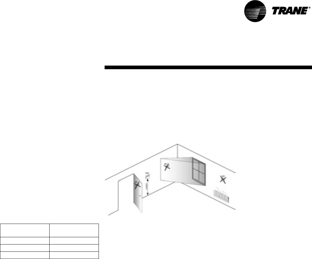
Thermostat Location
Location of the room thermostat/zone sensor cis an important element of effec-
tive room control.
Areas where the thermostat or zone sensor should not be located include : be-
hind doors, or corners; Near hot or cold air ducts; Near radiant heat (heat emitted
from appliances or the sun); Near concealed pipes or chimneys; On outside walls
or other non conditioned surfaces; In airflows from adjacent zones or other units
(Figure 7).
Installation
Low Voltage Wiring
Figure 7: Thermostat/sensor location
20 WSHP-SVX04A-EN
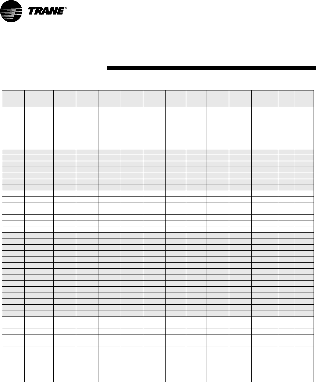
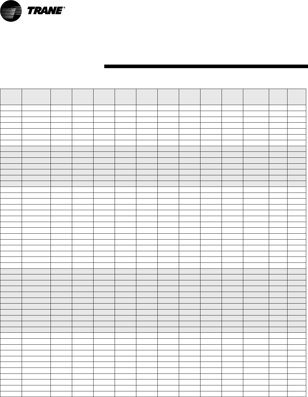
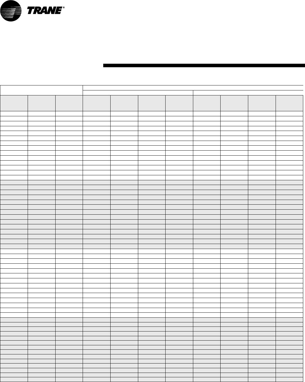
Table E1: WPVJ Electrical Performance (Standard Static Blower Option)
Model
No.
Volts/Hz/Ph Total
FLA
Comp.
RLA (ea)
Comp.
LRA (ea)
No. of
Compres.
Cmp
MCC
Blower
Motor
FLA
Blower
Motor
HP
Fan Motor
Num
Minimum
Circuit
Ampacity
Overcurrent
Protective
Device
Desup Desup
RLA
WPVJ018 208/60/1 10.1 9.30 47.0 1 13.0 0.80 1/8 1 12.4 20 No 0
WPVJ018 208/60/1 10.31 9.30 47.0 1 13.0 0.80 1/8 1 12.6 20 Yes 0.21
WPVJ018 220-240/50/1 9.81 8.60 39.0 1 12.0 1.00 1/5 1 12.0 20 No 0.21
WPVJ018 230/60/1 10.1 9.30 47.0 1 13.0 0.80 1/8 1 12.4 20 No 0
WPVJ018 230/60/1 10.31 9.30 47.0 1 13.0 0.80 1/8 1 12.6 20 Yes 0.21
WPVJ018 265/60/1 9.6 8.60 39.0 1 12.0 1.00 1/5 1 11.8 20 No 0
WPVJ018 265/60/1 9.81 8.60 39.0 1 12.0 1.00 1/5 1 12.0 20 Yes 0.21
WPVJ024 208/60/1 12.6 11.40 56.0 116.0 1.20 1/5 115.5 25 No 0
WPVJ024 208/60/1 12.81 11.40 56.0 116.0 1.20 1/5 115.7 25 Yes 0.21
WPVJ024 220-240/50/1 10.6 9.60 47.0 113.5 1.00 1/5 113.0 20 No 0
WPVJ024 230/60/1 12.6 11.40 56.0 116.0 1.20 1/5 115.5 25 No 0
WPVJ024 230/60/1 12.81 11.40 56.0 116.0 1.20 1/5 115.7 25 Yes 0.21
WPVJ024 265/60/1 10.81 9.60 47.0 113.5 1.00 1/5 113.2 20 Yes 0.21
WPVJ024 265/60/1 10.6 9.60 47.0 113.5 1.00 1/5 113.0 20 No 0
WPVJ030 208/60/1 15.1 13.60 67.0 1 19.0 1.50 1/4 1 18.5 30 No 0
WPVJ030 208/60/1 15.31 13.60 67.0 1 19.0 1.50 1/4 1 18.7 30 Yes 0.21
WPVJ030 220-240/50/1 13.4 12.10 58.0 1 17.0 1.30 1/4 1 16.4 25 No 0
WPVJ030 230/60/1 15.1 13.60 67.0 1 19.0 1.50 1/4 1 18.5 30 No 0
WPVJ030 230/60/1 15.31 13.60 67.0 1 19.0 1.50 1/4 1 18.7 30 Yes 0.21
WPVJ030 265/60/1 13.4 12.10 58.0 1 17.0 1.30 1/4 1 16.4 25 No 0
WPVJ030 265/60/1 13.61 12.10 58.0 1 17.0 1.30 1/4 1 16.6 25 Yes 0.21
WPVJ036 208/60/1 17.8 15.00 73.0 121.0 2.80 1/3 121.6 35 No 0
WPVJ036 208/60/1 18.01 15.00 73.0 121.0 2.80 1/3 121.8 35 Yes 0.21
WPVJ036 208/60/3 13.5 10.70 63.0 115.0 2.80 1/3 116.2 25 No 0
WPVJ036 208/60/3 13.71 10.70 63.0 115.0 2.80 1/3 116.4 25 Yes 0.21
WPVJ036 220-240/50/1 16.6 14.30 71.0 120.0 2.30 1/3 120.2 30 No 0
WPVJ036 230/60/1 17.8 15.00 73.0 121.0 2.80 1/3 121.6 35 No 0
WPVJ036 230/60/1 18.01 15.00 73.0 121.0 2.80 1/3 121.8 35 Yes 0.21
WPVJ036 230/60/3 13.5 10.70 63.0 115.0 2.80 1/3 116.2 25 No 0
WPVJ036 230/60/3 13.71 10.70 63.0 115.0 2.80 1/3 116.4 25 Yes 0.21
WPVJ036 265/60/1 16.6 14.30 71.0 120.0 2.30 1/3 120.2 30 No 0
WPVJ036 265/60/1 16.81 14.30 71.0 120.0 2.30 1/3 120.4 30 Yes 0.21
WPVJ036 380-415/50/3 6.1 5.00 31.0 17.0 1.10 1/3 17.4 15 No 0
WPVJ036 460/60/3 6.1 5.00 31.0 17.0 1.10 1/3 17.4 15 No 0
WPVJ036 460/60/3 6.31 5.00 31.0 17.0 1.10 1/3 17.6 15 Yes 0.21
WPVJ042 208/60/1 21.3 18.40 95.0 1 25.8 2.90 1/2 1 25.9 40 No 0
WPVJ042 208/60/1 21.51 18.40 95.0 1 25.8 2.90 1/2 1 26.1 40 Yes 0.21
WPVJ042 208/60/3 14.3 11.40 77.0 1 16.0 2.90 1/2 1 17.2 25 No 0
WPVJ042 208/60/3 14.51 11.40 77.0 1 16.0 2.90 1/2 1 17.4 25 Yes 0.21
WPVJ042 230/60/1 21.3 18.40 95.0 1 25.8 2.90 1/2 1 25.9 40 No 0
WPVJ042 230/60/1 21.51 18.40 95.0 1 25.8 2.90 1/2 1 26.1 40 Yes 0.21
WPVJ042 230/60/3 14.3 11.40 77.0 1 16.0 2.90 1/2 1 17.2 25 No 0
WPVJ042 230/60/3 14.51 11.40 77.0 1 16.0 2.90 1/2 1 17.4 25 Yes 0.21
WPVJ042 380-415/50/3 7.1 5.70 39.0 1 8.0 1.40 1/2 1 8.5 15 No 0
WPVJ042 460/60/3 7.1 5.70 39.0 1 8.0 1.40 1/2 1 8.5 15 No 0
WPVJ042 460/60/3 7.31 5.70 39.0 1 8.0 1.40 1/2 1 8.7 15 Yes 0.21
Electrical
Requirements
WSHP-SVX04A-EN 21
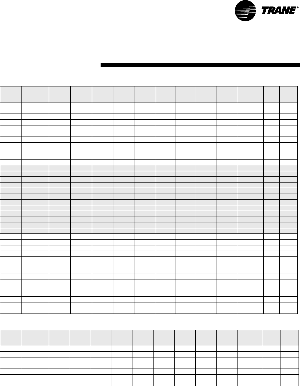
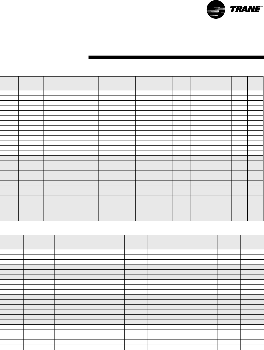
Table E1: WPVJ Electrical Performance (Standard Static Blower Option-continued)
Table E2: WPVJ Electrical Performance (High Static Blower Option)
Model
No.
Volts/Hz/Ph Total
FLA
Comp.
RLA (ea)
Comp.
LRA (ea)
No. of
Compres.
Cmp
MCC
Blower
Motor
FLA
Blower
Motor
HP
Fan Motor
Num
Minimum
Circuit
Ampacity
Overcurrent
Protective
Device
Desup Desup
RLA
WPVJ048 208/60/1 23.3 20.40 109.0 1 28.6 2.90 1/2 1 28.4 45 No 0
WPVJ048 208/60/1 23.51 20.40 109.0 1 28.6 2.90 1/2 1 28.6 45 Yes 0.21
WPVJ048 208/60/3 16.8 13.90 88.0 1 19.4 2.90 1/2 1 20.3 30 No 0
WPVJ048 208/60/3 17.01 13.90 88.0 1 19.4 2.90 1/2 1 20.5 30 Yes 0.21
WPVJ048 230/60/1 23.3 20.40 109.0 1 28.6 2.90 1/2 1 28.4 45 No 0
WPVJ048 230/60/1 23.51 20.40 109.0 1 28.6 2.90 1/2 1 28.6 45 Yes 0.21
WPVJ048 230/60/3 16.8 13.90 88.0 1 19.4 2.90 1/2 1 20.3 30 No 0
WPVJ048 230/60/3 17.01 13.90 88.0 1 19.4 2.90 1/2 1 20.5 30 Yes 0.21
WPVJ048 380-415/50/3 8.5 7.10 44.0 1 10.0 1.40 1/2 1 10.3 15 No 0
WPVJ048 460/60/3 8.5 7.10 44.0 1 10.0 1.40 1/2 1 10.3 15 No 0
WPVJ048 460/60/3 8.71 7.10 44.0 1 10.0 1.40 1/2 1 10.5 15 Yes 0.21
WPVJ060 208/60/1 32.2 28.00 169.0 139.0 4.20 3/4 139.2 60 No 0
WPVJ060 208/60/1 32.41 28.00 169.0 139.0 4.20 3/4 139.4 60 Yes 0.21
WPVJ060 208/60/3 23.5 19.30 123.0 127.0 4.20 3/4 128.3 45 No 0
WPVJ060 208/60/3 23.71 19.30 123.0 127.0 4.20 3/4 128.5 45 Yes 0.21
WPVJ060 230/60/1 32.2 28.00 169.0 139.0 4.20 3/4 139.2 60 No 0
WPVJ060 230/60/1 32.41 28.00 169.0 139.0 4.20 3/4 139.4 60 Yes 0.21
WPVJ060 230/60/3 23.5 19.30 123.0 127.0 4.20 3/4 128.3 45 No 0
WPVJ060 230/60/3 23.71 19.30 123.0 127.0 4.20 3/4 128.5 45 Yes 0.21
WPVJ060 380-415/50/3 9.6 7.50 49.5 110.5 2.10 3/4 111.5 15 No 0
WPVJ060 460/60/3 9.6 7.50 49.5 110.5 2.10 3/4 111.5 15 No 0
WPVJ060 460/60/3 9.81 7.50 49.5 110.5 2.10 3/4 111.7 15 Yes 0.21
WPVJ060 575/60/3 8.1 6.40 40.0 19.0 1.70 3/4 19.7 15 No 0
WPVJ060 575/60/3 8.31 6.40 40.0 1 9.0 1.70 3/4 1 9.9 15 Yes 0.21
WPVJ072 208/60/1 36.3 32.10 169.0 1 45.0 4.20 3/4 1 44.3 70 No 0
WPVJ072 208/60/1 36.51 32.10 169.0 1 45.0 4.20 3/4 1 44.5 70 Yes 0.21
WPVJ072 208/60/3 23.5 19.30 137.0 1 27.0 4.20 3/4 1 28.3 45 No 0
WPVJ072 208/60/3 23.71 19.30 137.0 1 27.0 4.20 3/4 1 28.5 45 Yes 0.21
WPVJ072 230/60/1 36.3 32.10 169.0 1 45.0 4.20 3/4 1 44.3 70 No 0
WPVJ072 230/60/1 36.51 32.10 169.0 1 45.0 4.20 3/4 1 44.5 70 Yes 0.21
WPVJ072 230/60/3 23.5 19.30 137.0 1 27.0 4.20 3/4 1 28.3 45 No 0
WPVJ072 230/60/3 23.71 19.30 137.0 1 27.0 4.20 3/4 1 28.5 45 Yes 0.21
WPVJ072 380-415/50/3 12.1 10.00 62.0 1 14.0 2.10 3/4 1 14.6 25 No 0
WPVJ072 460/60/3 12.1 10.00 62.0 1 14.0 2.10 3/4 1 14.6 25 No 0
WPVJ072 460/60/3 12.31 10.00 62.0 1 14.0 2.10 3/4 1 14.8 25 Yes 0.21
WPVJ072 575/60/3 9.6 7.90 50.0 1 11.0 1.70 3/4 1 11.6 15 No 0
WPVJ072 575/60/3 9.81 7.90 50.0 1 11.0 1.70 3/4 1 11.8 15 Yes 0.21
Model No.
Volts/Hz/Ph
Total
FLA
Comp.
RLA (ea)
Comp.
LRA (ea)
No. of
Compres.
Cmp
MCC
Blower
Motor
FLA
Blower
Motor
HP
Fan Motor
Num
Minimum
Circuit
Ampacity
Overcurrent
Protective
Device
Desup Desup
RLA
WPVJ018 208/60/1 10.5 9.30 47.0 1 13.0 1.20 1/5 1 12.8 20 No 0
WPVJ018 208/60/1 10.71 9.30 47.0 1 13.0 1.20 1/5 1 13.0 20 Yes 0.21
WPVJ018 220-240/50/1 9.6 8.60 39.0 1 12.0 1.00 1/5 1 11.8 20 No 0
WPVJ018 230/60/1 10.5 9.30 47.0 1 13.0 1.20 1/5 1 12.8 20 No 0
WPVJ018 230/60/1 10.71 9.30 47.0 1 13.0 1.20 1/5 1 13.0 20 Yes 0.21
WPVJ018 265/60/1 9.6 8.60 39.0 1 12.0 1.00 1/5 1 11.8 20 No 0
WPVJ018 265/60/1 9.81 8.60 39.0 1 12.0 1.00 1/5 1 12.0 20 Yes 0.21
Electrical
Requirements
22 WSHP-SVX04A-EN
Table E2: WPVJ Electrical Performance (High Static Blower Option-continued)
Model No.
Volts/Hz/Ph
Tota l
FLA
Comp.
RLA (ea)
Comp.
LRA (ea)
No. of
Compres.
Cmp
MCC
Blower
Motor
FLA
Blower
Motor
HP
Fan Motor
Num
Minimum
Circuit
Ampacity
Overcurrent
Protective
Device
Desup Desup
RLA
WPVJ024 208/60/1 12.9 11.40 56.0 1 16.0 1.50 1/4 1 15.8 25 No 0
WPVJ024 208/60/1 13.11 11.40 56.0 1 16.0 1.50 1/4 1 16.0 25 Yes 0.21
WPVJ024 220-240/50/1 10.9 9.60 47.0 1 13.5 1.30 1/4 1 13.3 20 No 0
WPVJ024 230/60/1 12.9 11.40 56.0 1 16.0 1.50 1/4 1 15.8 25 No 0
WPVJ024 230/60/1 13.11 11.40 56.0 1 16.0 1.50 1/4 1 16.0 25 Yes 0.21
WPVJ024 265/60/1 10.9 9.60 47.0 1 13.5 1.30 1/4 1 13.3 20 No 0
WPVJ024 265/60/1 11.11 9.60 47.0 1 13.5 1.30 1/4 1 13.5 20 Yes 0.21
WPVJ030 208/60/1 15.1 13.60 67.0 119.0 1.50 1/4 118.5 30 No 0
WPVJ030 208/60/1 15.31 13.60 67.0 119.0 1.50 1/4 118.7 30 Yes 0.21
WPVJ030 220-240/50/1 14.4 12.10 58.0 117.0 2.30 1/3 117.4 25 No 0
WPVJ030 230/60/1 15.1 13.60 67.0 119.0 1.50 1/4 118.5 30 No 0
WPVJ030 230/60/1 15.31 13.60 67.0 119.0 1.50 1/4 118.7 30 Yes 0.21
WPVJ030 265/60/1 14.4 12.10 58.0 117.0 2.30 1/3 117.4 25 No 0
WPVJ030 265/60/1 14.61 12.10 58.0 117.0 2.30 1/3 117.6 25 Yes 0.21
WPVJ036 208/60/1 17.8 15.00 73.0 1 21.0 2.80 1/3 1 21.6 35 No 0
WPVJ036 208/60/1 18.01 15.00 73.0 1 21.0 2.80 1/3 1 21.8 35 Yes 0.21
WPVJ036 208/60/3 13.5 10.70 63.0 1 15.0 2.80 1/3 1 16.2 25 No 0
WPVJ036 208/60/3 13.71 10.70 63.0 1 15.0 2.80 1/3 1 16.4 25 Yes 0.21
WPVJ036 220-240/50/1 16.6 14.30 71.0 1 20.0 2.30 1/3 1 20.2 30 No 0
WPVJ036 230/60/1 17.8 15.00 73.0 1 21.0 2.80 1/3 1 21.6 35 No 0
WPVJ036 230/60/1 18.01 15.00 73.0 1 21.0 2.80 1/3 1 21.8 35 Yes 0.21
WPVJ036 230/60/3 13.5 10.70 63.0 1 15.0 2.80 1/3 1 16.2 25 No 0
WPVJ036 230/60/3 13.71 10.70 63.0 1 15.0 2.80 1/3 1 16.4 25 Yes 0.21
WPVJ036 265/60/1 16.6 14.30 71.0 1 20.0 2.30 1/3 1 20.2 30 No 0
WPVJ036 265/60/1 16.81 14.30 71.0 1 20.0 2.30 1/3 1 20.4 30 Yes 0.21
WPVJ036 380-415/50/3 6.4 5.00 31.0 1 7.0 1.40 1/2 1 7.7 15 No 0
WPVJ036 460/60/3 6.4 5.00 31.0 1 7.0 1.40 1/2 1 7.7 15 No 0
WPVJ036 460/60/3 6.61 5.00 31.0 1 7.0 1.40 1/2 1 7.9 15 Yes 0.21
WPVJ042 208/60/1 21.3 18.40 95.0 125.8 2.90 1/2 125.9 40 No 0
WPVJ042 208/60/1 21.51 18.40 95.0 125.8 2.90 1/2 126.1 40 Yes 0.21
WPVJ042 208/60/3 14.3 11.40 77.0 116.0 2.90 1/2 117.2 25 No 0
WPVJ042 208/60/3 14.51 11.40 77.0 116.0 2.90 1/2 117.4 25 Ye s 0.21
WPVJ042 230/60/1 21.3 18.40 95.0 125.8 2.90 1/2 125.9 40 No 0
WPVJ042 230/60/1 21.51 18.40 95.0 125.8 2.90 1/2 126.1 40 Yes 0.21
WPVJ042 230/60/3 14.3 11.40 77.0 116.0 2.90 1/2 117.2 25 No 0
WPVJ042 230/60/3 14.51 11.40 77.0 116.0 2.90 1/2 117.4 25 Ye s 0.21
WPVJ042 380-415/50/3 7.1 5.70 39.0 18.0 1.40 1/2 18.5 15 No 0
WPVJ042 460/60/3 7.1 5.70 39.0 18.0 1.40 1/2 18.5 15 No 0
WPVJ042 460/60/3 7.31 5.70 39.0 18.0 1.40 1/2 18.7 15 Yes 0.21
WPVJ048 208/60/1 23.3 20.40 109.0 1 28.6 2.90 1/2 1 28.4 45 No 0
WPVJ048 208/60/1 23.51 20.40 109.0 1 28.6 2.90 1/2 1 28.6 45 Yes 0.21
WPVJ048 208/60/3 16.8 13.90 88.0 1 19.4 2.90 1/2 1 20.3 30 No 0
WPVJ048 208/60/3 17.01 13.90 88.0 1 19.4 2.90 1/2 1 20.5 30 Yes 0.21
WPVJ048 230/60/1 23.3 20.40 109.0 1 28.6 2.90 1/2 1 28.4 45 No 0
WPVJ048 230/60/1 23.51 20.40 109.0 1 28.6 2.90 1/2 1 28.6 45 Yes 0.21
WPVJ048 230/60/3 16.8 13.90 88.0 1 19.4 2.90 1/2 1 20.3 30 No 0
WPVJ048 230/60/3 17.01 13.90 88.0 1 19.4 2.90 1/2 1 20.5 30 Yes 0.21
WPVJ048 380-415/50/3 8.5 7.10 44.0 1 10.0 1.40 1/2 1 10.3 15 No 0
WPVJ048 460/60/3 8.5 7.10 44.0 1 10.0 1.40 1/2 1 10.3 15 No 0
WPVJ048 460/60/3 8.71 7.10 44.0 1 10.0 1.40 1/2 1 10.5 15 Yes 0.21
Electrical
Requirements
WSHP-SVX04A-EN 23
Table E2: WPVJ Electrical Performance (High Static Blower Option-continued)
Table E3: WPHF Electrical Performance (Standard Static Blower Option)
Model No.
Volts/Hz/Ph
Tota l
FLA
Comp.
RLA (ea)
Comp.
LRA (ea)
No. of
Compres.
Cmp
MCC
Blower
Motor
FLA
Blower
Motor
HP
Fan Motor
Num
Minimum
Circuit
Ampacity
Overcurrent
Protective
Device
Desup Desup
RLA
WPVJ060 208/60/1 33.5 28.00 169.0 1 39.0 5.50 3/4 1 40.5 60 No 0
WPVJ060 208/60/1 33.71 28.00 169.0 1 39.0 5.50 3/4 1 40.7 60 Yes 0.21
WPVJ060 208/60/3 24.8 19.30 123.0 1 27.0 5.50 3/4 1 29.6 45 No 0
WPVJ060 208/60/3 25.01 19.30 123.0 1 27.0 5.50 3/4 1 29.8 45 Yes 0.21
WPVJ060 230/60/1 33.5 28.00 169.0 1 39.0 5.50 3/4 1 40.5 60 No 0
WPVJ060 230/60/1 33.71 28.00 169.0 1 39.0 5.50 3/4 1 40.7 60 Yes 0.21
WPVJ060 230/60/3 24.8 19.30 123.0 1 27.0 5.50 3/4 1 29.6 45 No 0
WPVJ060 230/60/3 25.01 19.30 123.0 1 27.0 5.50 3/4 1 29.8 45 Yes 0.21
WPVJ060 380-415/50/3 10.8 7.50 49.5 1 10.5 3.30 3/4 1 12.7 20 No 0
WPVJ060 460/60/3 10.8 7.50 49.5 1 10.5 3.30 3/4 1 12.7 20 No 0
WPVJ060 460/60/3 11.01 7.50 49.5 1 10.5 3.30 3/4 1 12.9 20 Yes 0.21
WPVJ060 575/60/3 8.9 6.40 40.0 1 9.0 2.50 3/4 1 10.5 15 No 0
WPVJ060 575/60/3 9.11 6.40 40.0 1 9.0 2.50 3/4 1 10.7 15 Yes 0.21
WPVJ072 208/60/1 37.6 32.10 169.0 145.0 5.50 3/4 145.6 70 No 0
WPVJ072 208/60/1 37.81 32.10 169.0 145.0 5.50 3/4 145.8 70 Yes 0.21
WPVJ072 208/60/3 24.8 19.30 137.0 127.0 5.50 3/4 129.6 45 No 0
WPVJ072 208/60/3 25.01 19.30 137.0 127.0 5.50 3/4 129.8 45 Yes 0.21
WPVJ072 230/60/1 37.6 32.10 169.0 145.0 5.50 3/4 145.6 70 No 0
WPVJ072 230/60/1 37.81 32.10 169.0 145.0 5.50 3/4 145.8 70 Yes 0.21
WPVJ072 230/60/3 24.8 19.30 137.0 127.0 5.50 3/4 129.6 45 No 0
WPVJ072 230/60/3 25.01 19.30 137.0 127.0 5.50 3/4 129.8 45 Yes 0.21
WPVJ072 380-415/50/3 13.3 10.00 62.0 114.0 3.30 3/4 115.8 25 No 0
WPVJ072 460/60/3 13.3 10.00 62.0 114.0 3.30 3/4 115.8 25 No 0
WPVJ072 460/60/3 13.51 10.00 62.0 114.0 3.30 3/4 116.0 25 Yes 0.21
WPVJ072 575/60/3 10.4 7.90 50.0 111.0 2.50 3/4 112.4 20 No 0
WPVJ072 575/60/3 10.61 7.90 50.0 111.0 2.50 3/4 112.6 20 Yes 0.21
Model No.
Volts/Hz/Ph
Blower Motor
HP
Blower Motor
FLA
Compr.
RLA
Compr.
MCC
Compr.
LRA
Minimum Cir-
cuit Amps
UL Max Fuse
or HACR
CSA
Max. Fuse
Size
CASE
Max.
Circuit Brkr
WPHF021 208/60/1 1/8 1.3 8.0 12.5 45 11.3 15 20 15
WPHF021 230/60/1 1/8 1.3 8.0 12.5 45 11.3 15 20 15
WPHF021 265/60/1 1/8 1.1 7.0 10.9 39 9.9 15 20 15
WPHF027 208/60/1 1/5 1.2 11.0 17.2 60 15.0 25 30 25
WPHF027 230/60/1 1/5 1.2 11.0 17.2 60 15.0 25 30 25
WPHF027 265/60/1 1/5 2.4 9.6 15.0 52 14.4 20 25 20
WPHF035 208/60/1 1/5 2.0 12.4 19.4 65 17.5 30 35 25
WPHF035 230/60/1 1/5 2.0 12.4 19.4 65 17.5 30 35 25
WPHF035 265/60/1 1/5 2.4 10.8 16.9 57 15.9 25 30 25
WPHF040 208/60/1 1/3 2.8 15.1 23.5 85 21.7 35 45 35
WPHF040 230/60/1 1/3 2.8 15.1 23.5 85 21.7 35 45 35
WPHF040 265/60/1 1/3 2.0 13.2 20.5 74 18.5 30 40 30
WPHF040 208/60/3 1/3 2.8 10.6 16.5 101 16.1 25 50 40
WPHF040 230/60/3 1/3 2.8 10.6 16.5 101 13.1 25 50 40
WPHF040 265/60/3 1/3 2.0 4.2 6.6 51 7.3 15 25 20
WPHF047 208/60/1 1/3 2.8 14.6 22.8 92 21.1 35 50 40
WPHF047 230/60/1 1/3 2.8 14.6 22.8 92 21.1 35 50 40
WPHF047 208/60/3 1/3 2.8 10.6 16.5 101 16.1 25 50 40
WPHF047 230/60/3 1/3 2.8 10.6 16.5 101 16.1 25 50 40
WPHF047 460/60/3 1/3 1.1 4.2 6.6 51 6.4 15 25 20
Electrical
Requirements
24 WSHP-SVX04A-EN
Table E3: WPHF Electrical Performance (Standard Static Blower Option-continued)
Table E4: WPHF Electrical Performance (High Static Blower Option)
Model No.
Volts/Hz/Ph
Blower Motor
HP
Blower Motor
FLA
Compr.
RLA
Compr.
MCC
Compr.
LRA
Minimum Cir-
cuit Amps
UL Max Fuse
or HACR
CSA
Max. Fuse
Size
CASE
Max.
Circuit Brkr
WPHF057 208/60/1 1/2 4.1 22.3 34.8 122 32.0 50 60 50
WPHF057 230/60/1 1/2 4.1 22.3 34.8 122 32.0 50 60 50
WPHF057 208/60/3 1/2 4.1 14.4 25.5 101 22.1 35 50 45
WPHF057 230/60/3 1/2 4.1 14.4 25.5 101 22.1 35 50 45
WPHF057 460/60/3 1/2 1.8 7.1 11.1 51 10.7 15 20 20
Model No.
Volts/Hz/Ph
Blower Motor
HP
Blower Motor
FLA
Compr.
RLA
Compr.
MCC
Compr.
LRA
Minimum Cir-
cuit Amps
UL Max Fuse
or HACR
CSA
Max. Fuse
Size
CASE
Max.
Circuit Brkr
WPHF047 208/60/1 1/2 4.6 14.6 22.8 92 22.9 35 50 40
WPHF047 230/60/1 1/2 4.6 14.6 22.8 92 22.9 35 50 40
WPHF047 208/60/3 1/2 4.6 10.6 16.5 101 17.9 25 50 45
WPHF047 230/60/3 1/2 4.6 10.6 16.5 101 17.9 25 50 45
WPHF047 460/60/3 1/2 2.2 4.2 6.6 51 7.5 15 25 20
WPHF057 208/60/1 1/2 4.6 22.3 34.8 122 32.5 50 60 50
WPHF057 230/60/1 1/2 4.6 22.3 34.8 122 32.5 50 60 50
WPHF057 208/60/3 1/2 4.6 14.4 22.5 101 22.6 35 50 45
WPHF057 230/60/3 1/2 4.6 14.4 22.5 101 22.6 35 50 45
WPHF057 460/60/3 1/2 2.2 7.1 11.1 51 11.1 15 25 20
Electrical
Requirements

WSHP-SVX04A-EN 25
Pre-Start
Checklist
Pre-Start-up Checklist
Before energizing the unit, the following system devices must be checked:
____ Is the high voltage power supply correct and in accordance with the nameplate ratings?
____ Is the field wiring and circuit protection the correct size?
____ Is the low voltage control circuit wiring correct per the unit wiring diagram?
____ Is the piping system clean/complete and correct? (A recommendation of all system flushing of debris from
the water-to-refrigerant heat exchanger, along with air purging from the water-to-refrigerant heat exchanger
be done in accordance with the Closed-Loop/Ground Source Heat Pump Systems Installation Guide).
____ Is vibration isolation provided? (i.e. unit isolation pad, hosekits)
____ Is unit serviceable? (See clearance specifications on page 6).
____ Are the low/high-side pressure temperature caps secure and in place?
____ Are all the unit access panels secure and in place?
____ Is the thermostat in the OFF position?
____ Is the water flow established and circulating through all the units?
____ Is the duct work (if required) correctly sized, run, taped, insulated and weather proofed with proper unit
arrangement?
____ Is the condensate line properly sized, run, trapped and pitched?
____ Does the indoor blower turn freely without rubbing?
____ Has all work been done in accordance with applicable local and national codes?
____ Has heat transfer fluid been added in the proper mix to prevent freezing in closed system application?

26 WSHP-SVX04A-EN
Initial Unit Start-up
Start-up for 24V (basic) controls is included below:
Note: Start-up for the TracerTM ZN510 controller may be found in WSHP-IOP-2.
1.Set the thermostat to the highest position.
2.Set the thermostat system switch to COOL with the fan control to AUTO. The compressor should NOT run.
3.Reduce the temperature control setting until the compressor, reversing valve, solenoid valve, and loop pump
are energized. Adjust water flow utilizing pressure/temperature plugs and comparing to tables contained in
specification sheet data. Water leaving the heat exchanger should be warmer than the entering water temper-
ature (approximately 9°F-12°F); blower operation should be smooth; compressor and blower amps should be
within data plate ratings; the suction line should be cool with no frost observed in the refrigerant circuit.
4.Check the cooling refrigerant pressures against values in Table OP1. (Page 27).
5.Turn the thermostat switch to the OFF position. Unit should stop running and the reversing valve should de-
energize.
6.Leave unit off for approximately FIVE minutes to allow for pressure equalization.
7.Turn the thermostat to the lowest setting.
8.Set the thermostat system switch to the HEAT position.
9.Adjust the temperature setting upward until the unit is energized. Warm air should blow from the register. A
water temperature decrease of approximately 5°F-9°F leaving the heat exchanger should be noted. The
blower and compressor operation should be smooth with no frost observed in the refrigeration circuit.
10.Check the heating refrigerant pressures against values in Table OP1. (Page 27)
11.Set the thermostat to maintain the desired space temperature.
12.Instruct the owner on system operation.
Sequence
of Operation
WSHP-SVX04A-EN 27
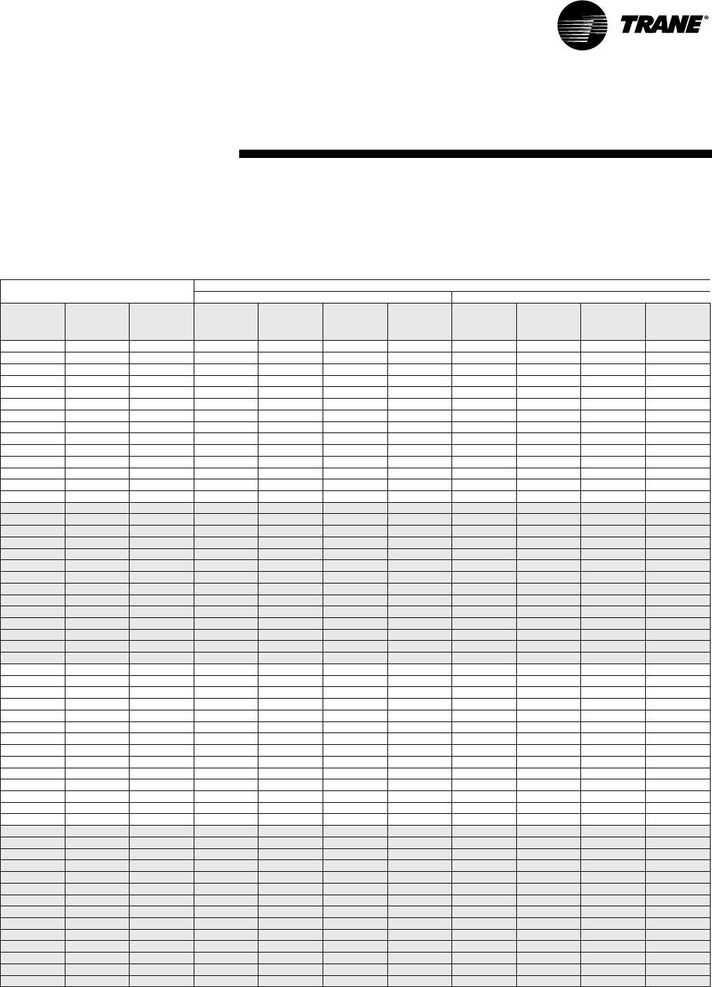
Operating Pressures
GENERAL: There are many variables (airflow, air temperatures) in an air conditioning system that will affect operating refrigerant pressures and
temperatures. The charts below shows approximate conditions and is based on air flow at the rated SCFM, entering air at 80.6 °F(DB), 66.2 °F(WB)
in cooling, 68 °F(DB) in heating. (+)Heating data with 35 °F EWT is based on the use of an anti-freeze solution having a freezing point 20 °F lower
than the minimum expected entering temperature.
Table OP-1: Operating pressures and temperature for PSC motor
Units with PSC motors Operating Data
Cooling Heating
Model Entering
Water Temp,
°F
Water
Flow
GPM
Suction Pres-
sure,
PSIG
Discharge
Pressure,
PSIG
Water
Tem p
Rise, °F
Air Temp
Drop, °FDB
Suction Pres-
sure,
PSIG
Discharge
Pressure,
PSIG
Water Temp
Drop, °F
Air Temp
Rise,
°FDB
WPVJ 018 35 4 42 - 49 176 - 224 2 - 2 21 - 27
WPVJ 018 35 5 43 - 50 177 - 226 2 - 2 22 - 28
WPVJ 018 45 4 66 - 76 101 - 129 11 - 14 20 - 25 51 - 58 188 - 239 3 - 3 25 - 31
WPVJ 018 45 5 66 - 76 98 - 125 9 - 11 20 - 26 52 - 60 189 - 241 2 - 3 25 - 32
WPVJ 018 55 4 69 - 79 119 - 152 11 - 14 20 - 25 59 - 68 199 - 253 3 - 4 28 - 35
WPVJ 018 55 5 68 - 78 116 - 147 9 - 11 20 - 25 60 - 70 200 - 255 3 - 3 29 - 36
WPVJ 018 68 4 71 - 82 146 - 186 11 - 13 19 - 24 70 - 81 212 - 270 4 - 5 32 - 40
WPVJ 018 68 5 71 - 81 142 - 181 8 - 11 19 - 24 72 - 82 214 - 273 3 - 4 33 - 42
WPVJ 018 75 4 72 - 83 162 - 207 10 - 13 18 - 24 76 - 88 220 - 280 4 - 5 34 - 43
WPVJ 018 75 5 72 - 82 158 - 201 8 - 11 19 - 24 78 - 90 222 - 282 4 - 5 35 - 44
WPVJ 018 86 4 73 - 84 191 - 243 10 - 13 18 - 23 86 - 99 232 - 295 5 - 6 37 - 47
WPVJ 018 86 5 73 - 84 186 - 237 8 - 11 18 - 23 88 - 101 234 - 298 4 - 5 38 - 49
WPVJ 018 95 4 74 - 85 217 - 277 10 - 13 17 - 22
WPVJ 018 95 5 74 - 85 212 - 270 8 - 10 17 - 22
WPVJ 024 35 4.88 42 - 49 177 - 225 3 - 4 21 - 27
WPVJ 024 35 6.1 43 - 49 178 - 227 3 - 3 22 - 27
WPVJ 024 45 4.88 64 - 74 103 - 132 11 - 1 3 19 - 24 51 - 58 187 - 238 4 - 5 24 - 30
WPVJ 024 45 6.1 64 - 73 100 - 128 9 - 11 19 - 25 51 - 59 189 - 240 3 - 4 25 - 31
WPVJ 024 55 4.88 68 - 78 120 - 153 11 - 1 3 19 - 24 60 - 68 197 - 251 4 - 6 27 - 34
WPVJ 024 55 6.1 67 - 77 11 7 - 14 9 8 - 11 19 - 24 60 - 69 199 - 253 4 - 5 27 - 35
WPVJ 024 68 4.88 71 - 82 147 - 187 10 - 13 18 - 23 71 - 82 210 - 268 5 - 7 30 - 39
WPVJ 024 68 6.1 71 - 81 143 - 182 8 - 11 18 - 23 72 - 83 212 - 270 4 - 5 31 - 40
WPVJ 024 75 4.88 72 - 83 164 - 208 10 - 13 18 - 22 77 - 89 218 - 277 6 - 7 32 - 41
WPVJ 024 75 6.1 72 - 83 159 - 202 8 - 11 18 - 23 78 - 90 220 - 280 5 - 6 33 - 42
WPVJ 024 86 4.88 74 - 85 193 - 245 10 - 13 17 - 22 86 - 99 229 - 292 6 - 8 35 - 45
WPVJ 024 86 6.1 74 - 85 187 - 238 8 - 11 17 - 22 87 - 100 232 - 295 5 - 7 36 - 46
WPVJ 024 95 4.88 75 - 87 219 - 279 10 - 13 17 - 21
WPVJ 024 95 6.1 75 - 87 213 - 271 8 - 11 17 - 22
WPVJ 030 35 5.76 43 - 50 163 - 207 4 - 5 21 - 26
WPVJ 030 35 7.2 43 - 50 164 - 209 3 - 4 21 - 27
WPVJ 030 45 5.76 63 - 72 103 - 131 11 - 14 19 - 24 51 - 59 172 - 219 4 - 5 23 - 29
WPVJ 030 45 7.2 61 - 71 98 - 125 9 - 11 19 - 24 52 - 59 173 - 221 4 - 5 24 - 30
WPVJ 030 55 5.76 68 - 79 121 - 154 11 - 14 18 - 23 59 - 68 179 - 228 5 - 6 26 - 32
WPVJ 030 55 7.2 67 - 77 116 - 148 9 - 11 18 - 24 60 - 68 181 - 230 4 - 5 26 - 33
WPVJ 030 68 5.76 72 - 83 148 - 188 11 - 14 18 - 23 68 - 78 188 - 239 6 - 7 28 - 36
WPVJ 030 68 7.2 72 - 83 142 - 181 9 - 11 18 - 23 69 - 79 189 - 241 5 - 6 29 - 37
WPVJ 030 75 5.76 74 - 85 164 - 209 11 - 14 17 - 22 73 - 83 193 - 246 6 - 8 30 - 38
WPVJ 030 75 7.2 73 - 85 158 - 201 9 - 11 18 - 22 73 - 84 195 - 248 5 - 6 30 - 39
WPVJ 030 86 5.76 76 - 87 192 - 244 11 - 14 17 - 22 78 - 90 199 - 253 7 - 8 32 - 40
WPVJ 030 86 7.2 76 - 87 185 - 235 9 - 11 17 - 22 78 - 90 200 - 254 5 - 7 32 - 41
WPVJ 030 95 5.76 77 - 89 217 - 276 11 - 14 17 - 21
WPVJ 030 95 7.2 77 - 89 209 - 266 9 - 11 17 - 21
WPVJ 036 35 6.88 41 - 47 162 - 206 4 - 5 20 - 25
WPVJ 036 35 8.6 42 - 48 162 - 206 3 - 4 21 - 26
WPVJ 036 45 6.88 66 - 76 109 - 138 11 - 14 19 - 25 50 - 57 170 - 217 5 - 6 22 - 29
WPVJ 036 45 8.6 66 - 75 105 - 134 9 - 12 19 - 25 51 - 58 170 - 217 4 - 5 23 - 29
WPVJ 036 55 6.88 71 - 81 126 - 161 11 - 14 19 - 24 59 - 68 180 - 229 6 - 7 25 - 32
WPVJ 036 55 8.6 70 - 81 122 - 155 9 - 12 19 - 24 60 - 69 180 - 229 5 - 6 26 - 33
WPVJ 036 68 6.88 74 - 85 154 - 195 11 - 14 18 - 24 71 - 82 192 - 244 7 - 8 29 - 37
WPVJ 036 68 8.6 73 - 84 148 - 188 9 - 11 19 - 24 72 - 83 192 - 244 5 - 7 30 - 38
WPVJ 036 75 6.88 75 - 86 170 - 217 11 - 14 18 - 23 77 - 89 198 - 251 7 - 9 31 - 39
WPVJ 036 75 8.6 74 - 86 164 - 209 9 - 11 18 - 23 78 - 90 198 - 252 6 - 7 31 - 40
WPVJ 036 86 6.88 77 - 88 200 - 255 11 - 1 4 18 - 22 85 - 97 206 - 262 8 - 10 33 - 42
WPVJ 036 86 8.6 76 - 88 193 - 246 9 - 11 18 - 23 86 - 99 206 - 263 6 - 8 33 - 43
WPVJ 036 95 6.88 78 - 90 228 - 290 11 - 1 4 17 - 22
WPVJ 036 95 8.6 78 - 89 220 - 280 9 - 11 17 - 22
Operating Pressures
WPVJ
28 WSHP-SVX04A-EN
Table OP-1: Operating pressures and temperature for PSC motor
Units with PSC motors Operating Data
Cooling Heating
Model Entering
Water Temp,
°F
Water
Flow
GPM
Suction Pres-
sure,
PSIG
Discharge
Pressure,
PSIG
Water
Tem p
Rise, °F
Air Temp
Drop, °FDB
Suction Pres-
sure,
PSIG
Discharge
Pressure,
PSIG
Water Temp
Drop, °F
Air Temp
Rise,
°FDB
WPVJ 042 35 8.08 42 - 48 164 - 209 5 - 6 19 - 25
WPVJ 042 35 10.1 43 - 49 165 - 210 4 - 5 20 - 25
WPVJ 042 45 8.08 63 - 72 108 - 137 12 - 16 24 - 30 50 - 57 171 - 218 5 - 7 22 - 28
WPVJ 042 45 10.1 60 - 69 105 - 134 10 - 12 24 - 30 51 - 58 172 - 219 4 - 6 22 - 28
WPVJ 042 55 8.08 69 - 79 124 - 158 12 - 15 22 - 28 58 - 67 181 - 230 6 - 8 25 - 32
WPVJ 042 55 10.1 67 - 77 121 - 154 10 - 12 22 - 28 60 - 69 182 - 231 5 - 6 25 - 32
WPVJ 042 68 8.08 75 - 86 150 - 191 12 - 15 21 - 26 69 - 80 192 - 245 7 - 9 28 - 36
WPVJ 042 68 10.1 73 - 84 145 - 185 9 - 12 21 - 26 70 - 81 193 - 246 6 - 7 28 - 36
WPVJ 042 75 8.08 77 - 88 165 - 211 11 - 15 20 - 26 73 - 84 196 - 249 7 - 10 29 - 37
WPVJ 042 75 10.1 75 - 86 160 - 204 9 - 12 20 - 26 74 - 85 197 - 250 6 - 8 29 - 38
WPVJ 042 86 8.08 79 - 91 193 - 246 11 - 14 19 - 25 76 - 87 199 - 253 8 - 10 30 - 38
WPVJ 042 86 10.1 77 - 89 187 - 238 9 - 12 20 - 25 77 - 88 200 - 254 6 - 8 30 - 39
WPVJ 042 95 8.08 80 - 92 218 - 278 11 - 14 19 - 24
WPVJ 042 95 10.1 79 - 91 212 - 270 9 - 11 19 - 24
WPVJ 048 35 9.2 44 - 51 170 - 216 5 - 7 23 - 29
WPVJ 048 35 11. 5 44 - 50 171 - 218 4 - 6 23 - 29
WPVJ 048 45 9.2 58 - 67 109 - 139 11 - 14 20 - 26 53 - 62 180 - 230 6 - 8 26 - 33
WPVJ 048 45 11. 5 56 - 64 103 - 131 9 - 12 20 - 26 53 - 61 182 - 231 5 - 7 26 - 34
WPVJ 048 55 9.2 65 - 75 129 - 164 11 - 1 4 19 - 25 63 - 72 192 - 244 7 - 9 29 - 37
WPVJ 048 55 11. 5 64 - 73 123 - 156 9 - 11 19 - 25 62 - 71 193 - 246 6 - 8 29 - 38
WPVJ 048 68 9.2 71 - 81 156 - 199 11 - 1 4 19 - 24 72 - 82 204 - 260 8 - 10 32 - 41
WPVJ 048 68 11. 5 70 - 80 149 - 190 9 - 11 19 - 24 71 - 82 205 - 261 7 - 9 33 - 41
WPVJ 048 75 9.2 73 - 83 172 - 219 11 - 14 18 - 23 75 - 86 208 - 265 9 - 11 33 - 42
WPVJ 048 75 11. 5 72 - 83 165 - 210 9 - 11 18 - 23 74 - 85 210 - 267 7 - 9 34 - 43
WPVJ 048 86 9.2 75 - 86 200 - 255 11 - 14 18 - 22 78 - 90 214 - 272 9 - 11 34 - 44
WPVJ 048 86 11. 5 74 - 85 192 - 245 9 - 11 18 - 23 77 - 89 215 - 274 7 - 9 35 - 44
WPVJ 048 95 9.2 76 - 87 226 - 288 11 - 14 17 - 22
WPVJ 048 95 11. 5 76 - 87 218 - 277 9 - 11 17 - 22
WPVJ 060 35 11.92 41 - 47 160 - 204 6 - 7 20 - 26
WPVJ 060 35 14.9 41 - 47 162 - 206 4 - 6 21 - 26
WPVJ 060 45 11.92 66 - 75 110 - 140 13 - 16 23 - 30 51 - 58 169 - 215 6 - 8 23 - 29
WPVJ 060 45 14.9 64 - 73 106 - 135 10 - 13 23 - 30 51 - 59 171 - 217 5 - 7 24 - 30
WPVJ 060 55 11.92 72 - 82 128 - 163 12 - 16 23 - 29 61 - 70 179 - 228 7 - 9 26 - 33
WPVJ 060 55 14.9 71 - 82 123 - 157 10 - 13 23 - 29 61 - 70 180 - 230 6 - 8 27 - 34
WPVJ 060 68 11.92 74 - 85 155 - 197 12 - 15 21 - 27 73 - 84 194 - 247 9 - 11 30 - 38
WPVJ 060 68 14.9 74 - 85 149 - 190 10 - 12 22 - 27 74 - 85 195 - 249 7 - 9 31 - 39
WPVJ 060 75 11.92 74 - 85 171 - 218 12 - 15 21 - 27 80 - 92 202 - 257 9 - 12 32 - 41
WPVJ 060 75 14.9 74 - 85 165 - 210 9 - 12 21 - 27 81 - 93 203 - 258 7 - 10 33 - 41
WPVJ 060 86 11.92 75 - 86 199 - 254 11 - 14 20 - 25 88 - 101 207 - 264 10 - 13 35 - 44
WPVJ 060 86 14.9 75 - 86 193 - 246 9 - 12 20 - 25 89 - 102 209 - 266 8 - 10 35 - 45
WPVJ 060 95 11.92 76 - 87 225 - 286 11 - 14 19 - 24
WPVJ 060 95 14.9 76 - 87 218 - 278 9 - 11 19 - 24
WPVJ 072 35 13.2 37 - 43 163 - 207 6 - 7 20 - 26
WPVJ 072 35 16.5 40 - 47 164 - 209 5 - 6 21 - 27
WPVJ 072 45 13.2 64 - 74 119 - 152 12 - 16 23 - 29 46 - 53 173 - 220 7 - 8 23 - 29
WPVJ 072 45 16.5 62 - 72 113 - 144 10 - 13 23 - 29 50 - 58 174 - 222 5 - 7 24 - 30
WPVJ 072 55 13.2 69 - 80 137 - 175 12 - 15 22 - 28 57 - 65 185 - 236 8 - 10 27 - 34
WPVJ 072 55 16.5 68 - 78 131 - 167 10 - 12 22 - 28 61 - 70 187 - 238 6 - 8 27 - 34
WPVJ 072 68 13.2 71 - 82 162 - 207 12 - 15 21 - 27 70 - 80 201 - 256 9 - 12 31 - 40
WPVJ 072 68 16.5 71 - 82 155 - 197 9 - 12 21 - 27 74 - 85 203 - 258 7 - 9 32 - 40
WPVJ 072 75 13.2 72 - 83 178 - 226 12 - 15 21 - 26 75 - 87 207 - 264 10 - 12 33 - 42
WPVJ 072 75 16.5 72 - 82 170 - 216 9 - 12 21 - 26 79 - 91 209 - 266 8 - 10 33 - 42
WPVJ 072 86 13.2 73 - 84 205 - 261 11 - 14 20 - 25 81 - 94 216 - 274 10 - 13 34 - 44
WPVJ 072 86 16.5 72 - 83 197 - 250 9 - 11 20 - 25 85 - 98 217 - 276 8 - 11 35 - 44
WPVJ 072 95 13.2 74 - 85 230 - 292 11 - 14 19 - 24
WPVJ 072 95 16.5 73 - 84 221 - 281 9 - 11 19 - 24
Operating Pressure
WSHP-SVX04A-EN 29
Operating Pressures
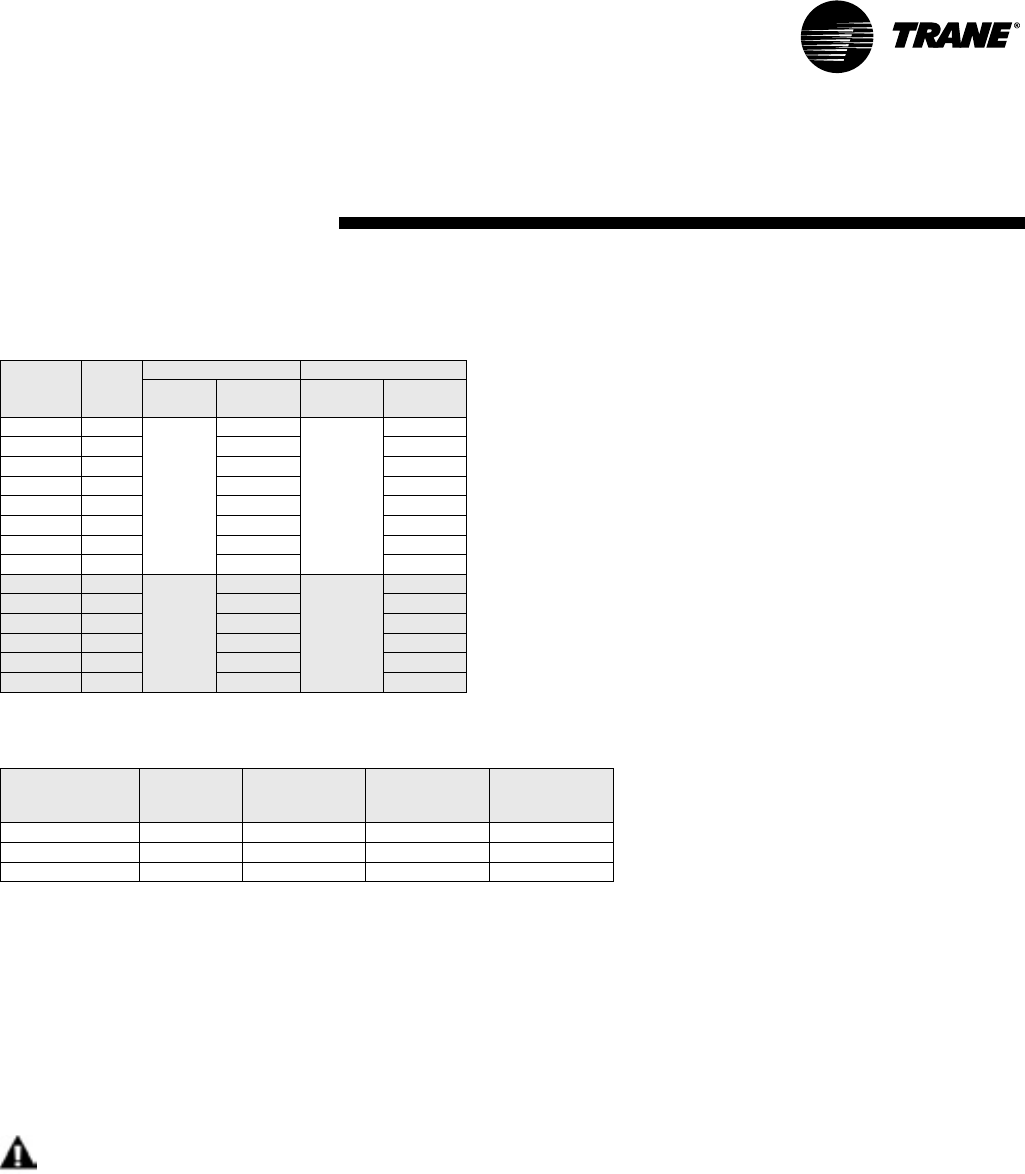
Water Pressure Drop
Table 4 should be used to define feet of head/pressure drop. Note: To calculate feet of head, when using gauges that read
in PSIG, multiply PSI by 2.31.
Water Volume
Table 5 is provided for use in calculating glycol requirements for the WPVJ unit.
Flow Checks
For the operating temperature drop (heating) and rise (cooling), refer to Table OP1 and OP2 for the proper water tempera-
ture change. Depending on the unit size, entering water temperature and water flow rate, the cooling temperature rise is
from 8°F-16°F. Based on the same criteria for heating, the temperature drop is from 2°F-13°F.
Pressure
Using the P/T ports and one 0-60 psi pressure gauge with the P/T port adapter, measure the pressure difference between
the water-in and water-out connections.
Start-up Checklist and Log
Use the form on page 30 to log system and unit temperatures during start-up.
WARNING
Live Electrical Components!
During installation, testing, servicing and troubleshooting of this product, it may be necessary to work with
live electrical components. Have a qualified licensed electrician or other individual who has been properly
trained in handling live electrical components perform these tasks. Failure to follow all electrical safety pre-
cautions when exposed to live electrical components could result in death or serious injury.
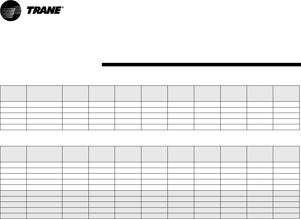
Table 4: Water pressure drops (WPD) in feet of head
Unit Size GPM
Cooling Heating
EWT
F
Ft. Head
Pressure
EWT
F
Ft. Head
Pressure
WPVJ 018 5.0
77
7. 5
55
9.0
WPVJ 024 6.1 10.2 12.1
WPVJ 030 7. 2 4 . 9 6 . 0
WPVJ 036 8.6 6.7 7.9
WPVJ 042 10.1 8.8 10.0
WPVJ 048 11.5 7.8 9.0
WPVJ 060 14.9 12.4 14.1
WPVJ 072 16.5 14.8 14.1
WPHF 021 5.3
77
6.9
55
7. 6
WPHF 027 6.8 11. 1 12.3
WPHF 035 8.7 17.9 19.8
WPHF 040 9.9 23.1 25.6
WPHF 047 11. 6 15.0 16.6
WPHF 057 14.1 22.0 24.4
Unit
Model
Unit
Size
Water Side
Volume
Cubic In.
Water Side
Volume
Cubic In.
Water Side
Volume
Gallons.
WPVJ 018-024 55 0.032 0.238
WPVJ 030-042 105 0.061 0.455
WPVJ 048-072 259 0.150 1.121
30 WSHP-SVX04A-EN
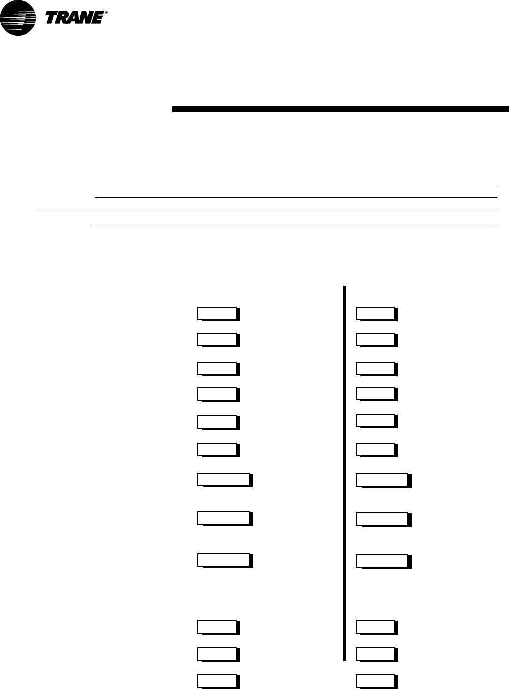
Start-up Checklist
and Log
Installing Contractor: Use this form to thoroughly check-out the system and units before and during
start-up. (This form need not be returned to the factory unless requested during technical service support).
Job Name:
Model Number:
Date:
Serial Number:
In order to minimize troubleshooting and costly system failures, complete the following checks and data
entries before the system is put into full operation.
MODE
Entering fluid temperature
Leaving fluid temperature
Temperature differential
Return-air temperature DB/WB
Supply-air temperature DB/WB
Temperature differential
Water coil heat exchanger
(Water Pressure IN)
Water coil heat exchanger
(Water Pressure OUT)
Pressure Differential
HEAT
F
COOL
F
F F
F F
PSIG PSIG
PSIG PSIG
PSIG PSIG
COMPRESSOR
Amps
Volts
Discharge line temperature
(after 10 minutes)
F F
F
F
F
F
F
F
WSHP-SVX04A-EN 31
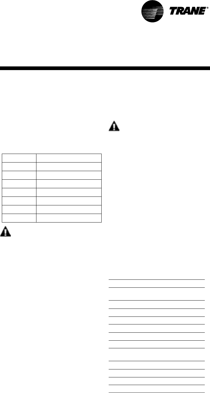
Preventive Maintenance
Maintenance on the unit is simplified
with the following preventive sugges-
tions:
Filter maintenance must be performed
to assure proper operation of the
equipment. Filters should be inspect-
ed at least every three months, and re-
placed when it is evident they are
dirty. Filter sizing includes:
WARNING
Hazardous
Voltage!
Disconnect all electric power, in-
cluding remote disconnects be-
fore servicing. Follow proper
lockout/tagout procedures to en-
sure the power can not be inad-
vertently energized. Failure to
disconnect power before servic-
ing could result in death or seri-
ous injury.
Check the contactors and relays within
the control panel at least once a year.
It is good practice to check the tight-
ness of the various wiring connections
within the control panel.
A strainer (60 mesh or greater) must
be used on an open loop system to
keep debris from entering the unit heat
exchanger and to ensure a clean sys-
tem.
For units on well water, it is important
to check the cleanliness of the water-
to-refrigerant heat exchanger. Should
it become contaminated with dirt and
scaling as a result of bad water, the
Model WPVJ Filter Size (nominal)
018, 024 16 x 20
030-042 20 x 25
048-072 20 x 30
Model WPHF Filter Size (nominal)
021-027 16 x 24
035-040 (1) 16 x 16 (1) 16 x 20
047-057 18 x 20
Maintenance
heat exchanger will have to be back
flushed and cleaned with a chemical
that will remove the scale. This service
should be performed by an experi-
enced service person.
WARNING
Hazardous
Chemicals!
Coil cleaning agents can be either
acidic or highly alkaline. Handle
chemical carefully. Proper han-
dling should include goggles or
face shield, chemical resistant
gloves, boots, apron or suit as re-
quired. For personal safety, refer
to the cleaning agent manufactur-
ers Materials Safety Data Sheet
and follow all recommended safe
handling practices. Failure to fol-
low all safety instructions could
result in death or serious injury.
It should be noted that the water qual-
ity should be checked periodically. See
Table 6.
Table 6: Water Quality Table
Scaling
Calcium and magnesium
(total hardness) Less than 350 ppm
Corrosion
pH 7-9.5
Hydrogen Sulfide Less than 1 ppm
Sulfates Less than 25 ppm
Chlorides Less than 125 ppm
Carbon Dioxide Less than 75 ppm
Total dissolved solids
(TDS) Less than 1000 ppm
Biological Growth
Iron Bacteria Low
Erosion
Suspended Solids Low

32 WSHP-SVX04A-EN
Warranty Information
Standard Warranty
The standard water-source heat pump warranty is Trane’s parts-only warranty, running 12-months from star-
tup, not to exceed 18-months from shipment.
Extended Warranty
The optional extended warranty is a second through fifth year warranty. The time starts at the end of standard
1-year coverage through the fifth year.
These extended warranties apply only to new equipment installed in domestic Trane Commercial Systems
Group sales territories and must be ordered prior to start-up.
Warranty
Information

WSHP-SVX04A-EN 33
WARNING
Hazardous Service
Procedures!
The maintenance and trouble
shooting procedures recommend-
ed in this section of the manual
could result in exposure to electri-
cal, mechanical or other potential
safety hazards. Always refer to
the safety warnings provided
throughout this manual concern-
ing these procedures. When possi-
ble, disconnect all electrical
power including remote discon-
nects before servicing. Follow
proper lockout/tagout procedures
to ensure the power can not be in-
advertently energized. When nec-
essary to work with live electrical
components, have a qualified li-
censed electrician or other indi-
vidual who has been trained in
handling live electrical compo-
nents per these tasks. Failure to
follow all of the recommended
safety warnings provided, could
result in death or serious injury.
Preliminary Trouble Inspection
If operational difficulties are encoun-
tered, be sure to perform the prelimi-
nary checks before referring to the
troubleshooting chart on page 34.
• Verify that the unit is receiving elec-
tric supply power.
• Ensure that the fuses in the fused
disconnect are intact.
After completing the preliminary
checks, inspect the unit for other obvi-
ous problems such as leaking connec-
tion, broken or disconnected wires,
etc. If everything appears to be in or-
der, but the unit still fails to operate
properly, refer to the troubleshooting
chart on page 34.
General Operation
The standard model is designed for in-
door installation. When the unit is in-
stalled in an unconditioned space, the
unit may not start in cool weather (ap-
proximately 45°F). It may then be nec-
essary to start the unit in the cooling
mode for three to five minutes. The
unit may then be shut-off (there will be
a two minute time-out of the unit), and
restarted in the heating mode.
Like any other type of mechanical
equipment, the unit performs best
when it is well maintained.
Operation with a Conventional
Thermostat
The unit is equipped with safety con-
trols, including high pressure control
and low pressure control to shut off
the compressor under abnormal pres-
sure conditions. If the safeties shut off
the compressor, a lockout relay pre-
vents short cycling from the abnormal
condition. When conditions are cor-
rected, the lockout control can be reset
by setting the thermostat system
switch to OFF wait a few minutes for
the system pressure to equalize, and
then return to HEAT or COOL. If the
condition continues, an authorized
service person should check out the
unit.
Troubleshooting
34 WSHP-SVX04A-EN
Troubleshooting
Checklist
Problem Heating Cooling Cause Correction
No response to any
thermostat setting
X X Main power off Check fuses
X X Defective control transformer Replace
X X Broken or loose connection Repair
X X Defective thermostat Replace
X X Transformer Reset Transformer
Unit short cycles X X Thermostat or sensor improperly located Relocate
Blower runs, but compressor does not
X X Defective compressor overload Replace (if external)
X X Defective compressor contactor Replace
X X Supply Voltage too low Correct
X X Defective compressor capacitor Replace
X X Defective windings Replace
X X Limit switches open Check cause/Replace or repair
Insufficient capacity
X X Dirty filter Replace/clean
X X Blower RPM too low Correct
XX
Loss of conditioned air due to leaks in
ductwork Repair leaks
X Introduction of excessively hot return-air Correct
X Introduction of excessively cold return-air Correct
X X Low on refrigerant charge Locate leak, repair and recharge by
weight (not by superheat)
X X Restricted thermal expansion valve Replace
X X Defective reversing valve Replace
X X Thermostat improperly located Relocate
X X Unit undersized Recalculate heat gains/losses
X X Inadequate water flow Increase GPM
X X Scaling in heat exchanger Clean or replace
X Water too hot Decrease temperature
X Water too cold Increase temperature
High pressure switch open
X Inadequate GPM Increase water flow to unit
X Water too hot Decrease temperature
X Inadequate air flow Check, clean blower and coil
X Dirty filter Clean/replace
X X Overcharged with refrigerant Decrease charge
X X Defective pressure switch Check or replace
High head pressure
X Trash in heat exchanger Backflush
X Low water flow Increase GPM
X X Overcharge of refrigerant Decrease charge
X X Non-condensable in system Evacuate and recharge by weight
X X Water too hot Decrease temperature
X Dirty filter Clean / replace
X Inadequate air flow Check, clean blower and coil
Low suction pressure
X X Undercharged Locate leak, repair and recharge
X X Restricted thermal expansion valve Repair / replace
X Inadequate air flow Check, clean blower and coil
X Dirty filter Clean/replace
X Inadequate GPM Increase GPM
Low Pressure switch open
X Inadequate GPM Increase GPM
X Water too cold Increase temperature
X Inadequate air flow Increase CFM
X Dirty filter Clean/replace
X X Undercharged with refrigerant Increase charge
X X Defective pressure switch Replace
X X Heat transfer fluid too cold Raise water temperature
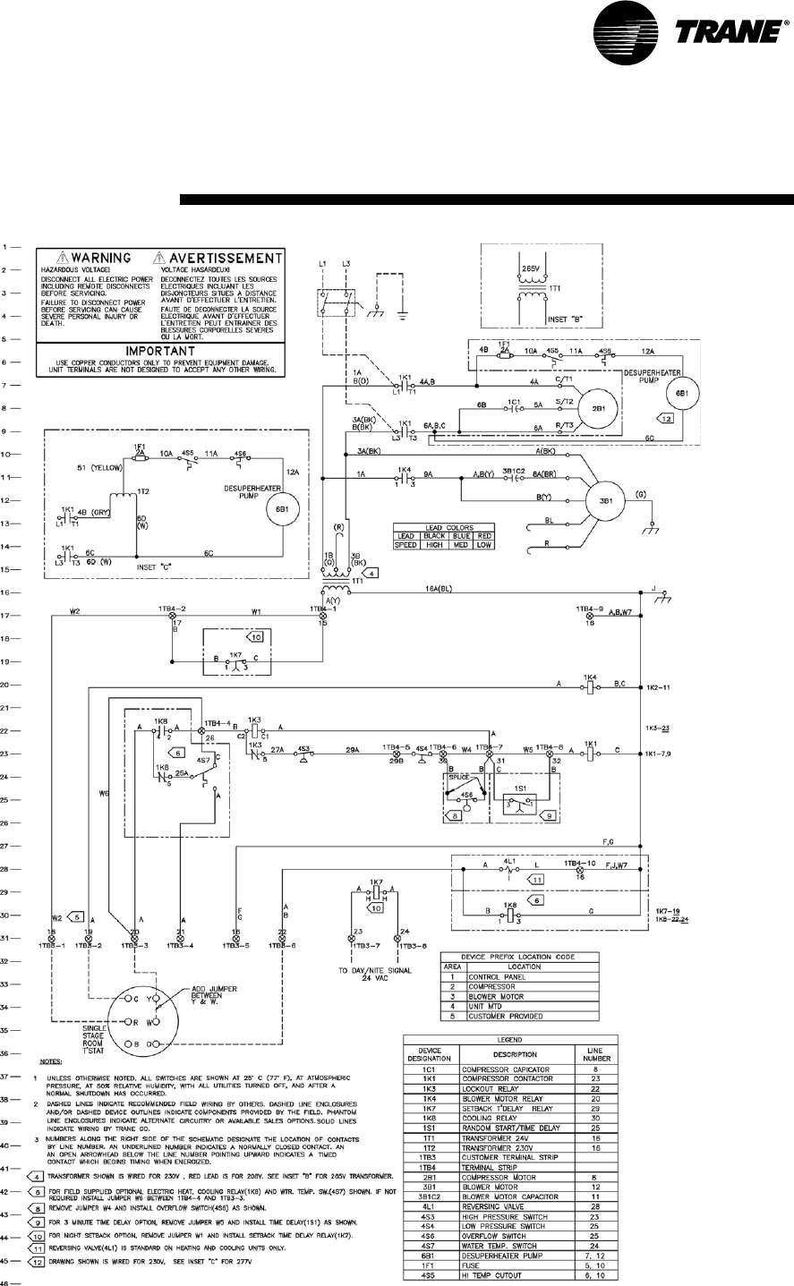
WSHP-SVX04A-EN 35
Unit Wiring
WPVJ Basic 24V Diagram
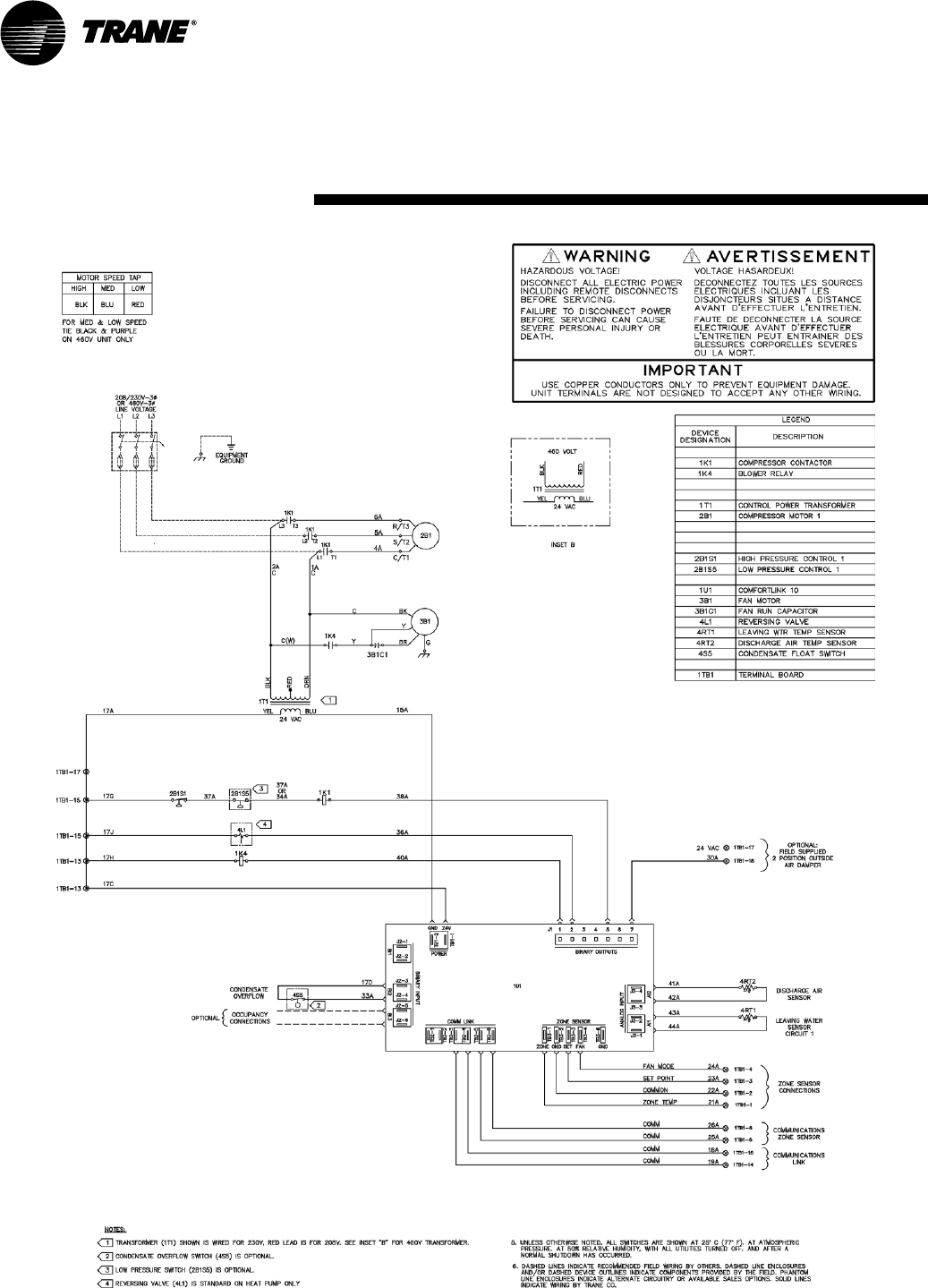
36 WSHP-SVX04A-EN
Unit Wiring
WPVJ Tracer ZN510 Diagram
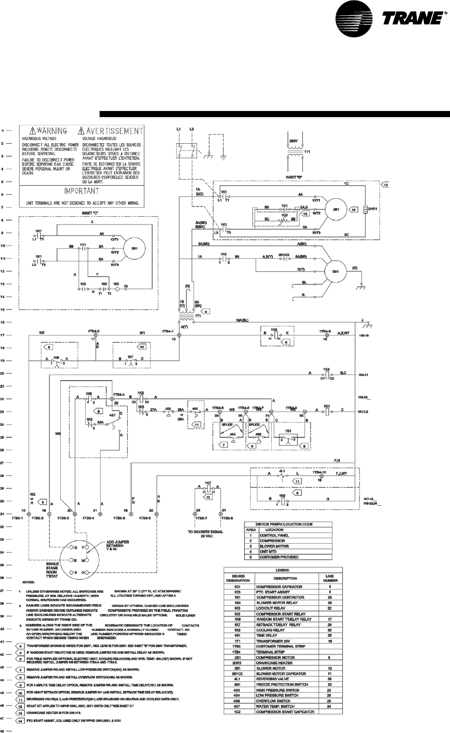
WSHP-SVX04A-EN 37
Unit Wiring
WPHF Basic 24V Diagram
38 WSHP-SVX04A-EN
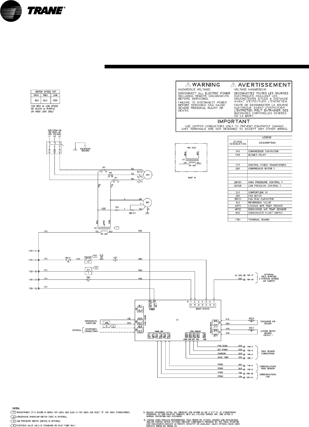
Unit Wiring
WPHF Tracer ZN510 Diagram

Trane has a policy of continuous product and data improvement and reserves the right to change
design and specifications without notice.
Literature Order Number WSHP-SVX04A-EN
File Number SV-UN-WSHP-SVX04A-0803
Supersedes WSHP-IOM-1, WPVF-IOM-1
Stocking Location Inland
Trane
A business of American Standard Companies
www.trane.com
For more information, contact your local district
office or e-mail us at comfort@trane.com
