Trane WSHP PRC001 EN User Manual To The 2cccaa90 Fb9c 41dc 99ed 196791b734c2
User Manual: Trane WSHP-PRC001-EN to the manual
Open the PDF directly: View PDF ![]() .
.
Page Count: 94
WSHP-PRC001-EN
March 2005
High Efficiency
Horizontal and Vertical
Water-Source Comfort System
AxiomTM
1/2 - 5 Tons — 60 HZ— Model GEH/GEV
©2005 American Standard Inc. All rights reserved. WSHP-PRC001-EN
Imagine a full range of comfort utiliz-
ing efficiency, sound attenuation, inte-
grated controls, and superior
maintenance accessibility... Trane
imagined it, and designed an ad-
vanced mechanical system.
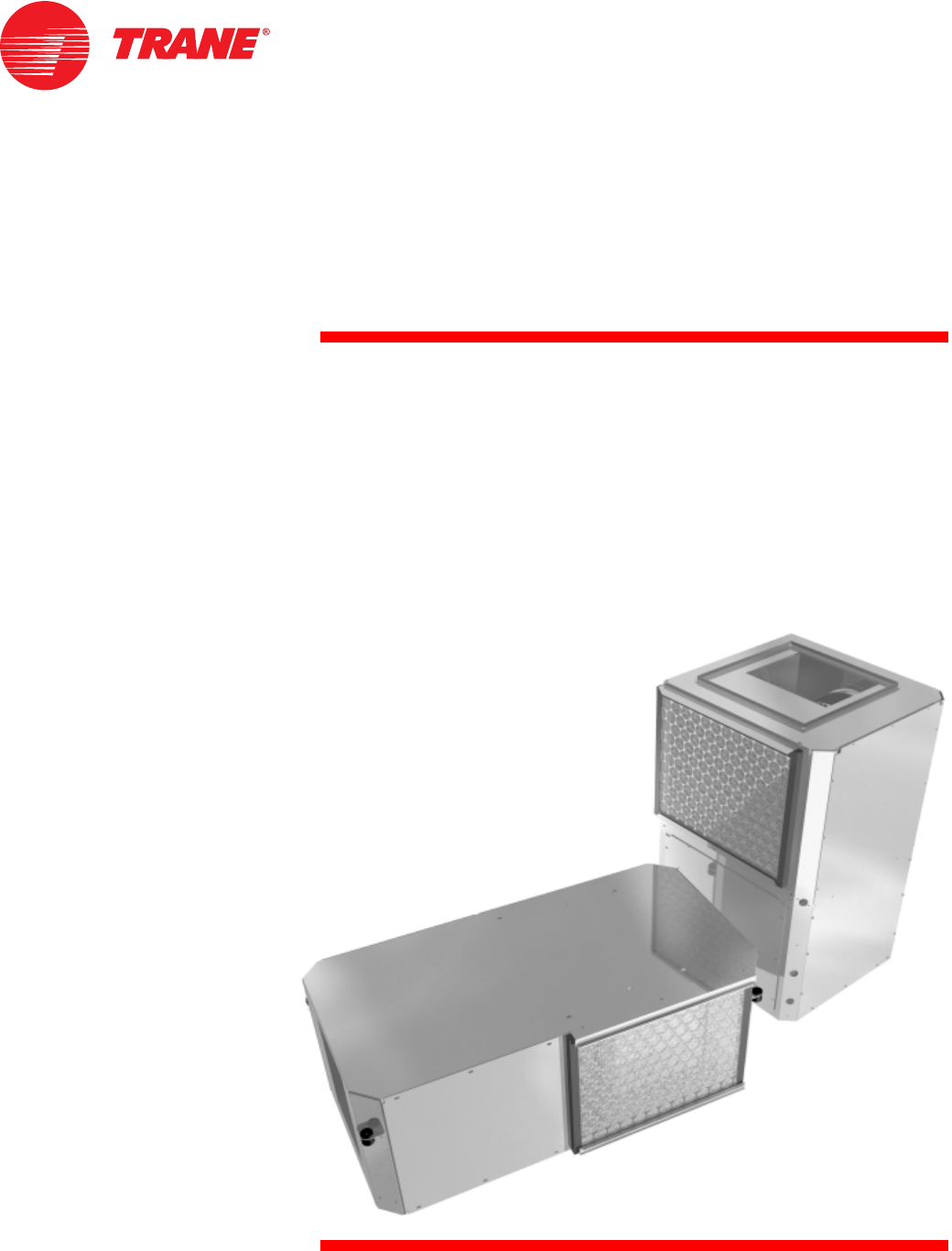
Introducing models GEH and GEV wa-
ter source comfort solutions.
Model GEH (pictured below) is a ceil-
ing hung product that provides a sleek,
innovative shape, along with convert-
ibility of the supply-air and the re-
turn-air arrangement; serviceability to
maintenance components; indoor air
quality standards; sound attenuation;
and best of all, higher efficiencies with
certified ARI-ISO 13256-1 perfor-
mance and ASHRAE 90.1 standards.
Trane’s new design incorporates sys-
tem advantages such as:
Maximum return-air and
supply-air flexibility
Superior maintenance
accessibility
Dual-sloped, plastic drain pan
Multi-speed motor
Insulated enclosure for quiet
unit design
Integrated controls
Orifice ring motor mounting
device as standard for ease of
motor service
High and low pressure
safeties as standard
Internal air-to-refrigerant coil
(horizontal design)
Introduction
1
2
3
4
5
6
7
8
9
WSHP-PRC001-EN 3
Table of Contents
Introduction 2
Features and Benefits 4
Options 4
Controls 14
Application Considerations 22
Selection Procedures 31
How to Select by Computer 31
Model Number Description 32
General Data 34
Performance Data 37
Cool and Heat Performance 38
Correction Factors 62
Electrical Performance 63
Fan Performance 66
Waterside Economizer Performance 68
Anti-Freeze Correction Factors 69
Controls 70
Wiring 70
Dimensional Data 74
Accessories 86
Thermostats 86
Options 88
Mechanical Specifications 90
4WSHP-PRC001-EN
Design Advantages
The horizontal and vertical configura-
tios range in capacities from 1/2 to 5
tons.
The innovative designs offers superior
field flexibility at the jobsite along with
service accessibility.
Model GEH Cabinet
The GEH cabinet design includes a
modular platform that utilizes similar
parts and assemblies throughout the
product line. It is constructed of heavy
gauge (non-painted) galvanized metal
for maximum durability and corrosive
resistive exterior.
The cabinet front allows service ac-
cess for the controls and refrigeration
circuitry. Water-in/out connection and
high/low voltage hook-up is accom-
plished at the 45-degree corners on
the front-side of the equipment.
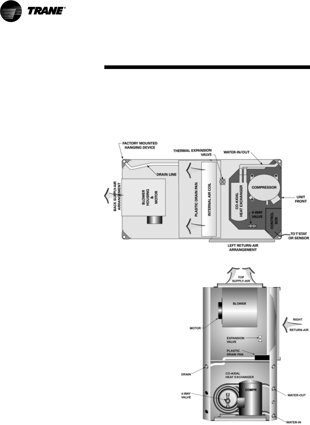
The unit offers six product variations
of return-air and supply-air combina-
tions which may be order-specific or
job-site modified. See Figure 1 compo-
nent platform location.
Model GEV Cabinet
The vertical design, model GEV
includes a 3 1/3-ton configuration
physically sized for condominium
installations.
The cabinet design contains a modular
platform utilizing similar parts and
assemblies to the horizontal to provide
a repetitious look and feel for
installation and maintenance
personnel. It is constructed of heavy
gauge (non-painted) galvanized metal
for maximum durability and corrosive
resistive exterior.
The cabinet front allows service access
for the controls and refrigeration
circuitry. Water-in/out connection,
drain connection, and high/low
voltage hook-up is accomplished at
the 45-degree chamfered corners on
the front-side of the equipment. The
vertical design offers four product
variations of return-air and supply-air
combinations.
The GEV model’s supply air
arrangement may be field converted
through a service kit to aid in stocking
of a single unit variation. See
Figure 2 for component platform
location.
Features and
Benefits
Figure 1: Component platform location
Figure 2: Component platform location
WSHP-PRC001-EN 5
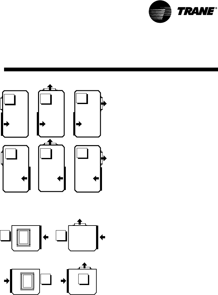
Supply/Return Air Combinations
The GEH model configuration may be
built to order or modified on-site to
meet unique installation require-
ments. The six combinations include:
1 Left return-air with left supply-air
combination
2 Left return-air with rear supply-air
combination
3 Left return-air with right supply-air
combination
4 Right return-air with left supply-air
combination
5 Right return-air with rear
supply-air combination
6 Right return-air with right
supply-air combination
See Figure 3 for the six field convert-
ible combinations.
GEV Flexibility
The GEV model is also capable of
on-site modifications. With the vertical
configuration, the supply-air is easily
converted from a top supply-air to a
back supply-air with a service retrofit
kit. The return-air option is order spe-
cific. The four combinations include:
1 Right return-air with top supply-air
combination
2 Right return-air with back supply-air
combination
3 Left return-air with top supply -air
combination
4 Left return-air with back supply-air
combination
See Figure 4 for the four supply-air/re-
turn-air combinations.
Features and
Benefits
Figure 3: Airflow combinations of
GEH 1/2 through 5-tons
UNIT
FRONT
1
UNIT
FRONT
2
UNIT
FRONT
3
UNIT
FRONT
4
Figure 4: Airflow combinations of
GEV 1/2 through 5-ton
123
456
UNIT
FRONT UNIT
FRONT
UNIT
FRONT
UNIT
FRONT
UNIT
FRONT
UNIT
FRONT
6WSHP-PRC001-EN
Hanging Device
The hanging bracket resides in the
chamfered corner of the horizontal 1/2
to 5 ton equipment. This partially-con-
cealed bracket design eliminates add-
ed height, width, or length to the
product. The brackets are factory
mounted to shorten job installation re-
quirements.
The structural integrity of the design
helps assure no bracket deflection or
unit bowing from the unit’s weight.
Field return-air hook-up and filter
maintenance are more simplistic. Iso-
lation for the hanging bracket is pro-
vided with a neoprene rubber
grommet design. This isolation device
helps prevent sound vibration from
reaching the structural support mem-
bers of the building during compres-
sor start and stop. See Figure 5 for
isolation device.
Drain Pan
The unit drain pan is composed of
plastic, corrosive resistive material.
The pan is positively sloped to comply
with ASHRAE 62 for (IAQ) indoor air
quality conformity.
Access to the drain pan is provided
through two access panels for clean-
ing purposes. See Figure 6 for plastic
drain pan.
Cabinet Insulation
The cabinet insulation design meets
UL 181 requirements. The air stream
surface of the insulation is fabricated
of a non-biodegradable source.
Refrigeration Piping
The unit’s copper tubing is created
from a 99% pure copper formation that
conforms to the American Society of
Testing (ASTM) B743 for seamless,
light-annealed processing.
The unit’s copper refrigeration system
is designed to be free from contami-
nants and conditions such as drilling
fragments, dirt, or oil. This excludes
the possibility of these contaminants
from damaging the compressor mo-
tor.
Compressor
The unit’s design includes a wide vari-
ety of compressor motors to accom-
modate dedicated voltages and
tonnage sizes. The 1/2 ton through
1 1/2 ton products embody a rotary
compressor design, where as unit siz-
es ranging from 2 ton through 4 ton in-
clude a reciprocating compressor
style, while the 5 ton unit contains a
scroll compressor. These different
styles allow Trane to provide the volt-
age variations along with noise reduc-
tion required in today’s applications.
See Figure 7 for reciprocating com-
pressor.
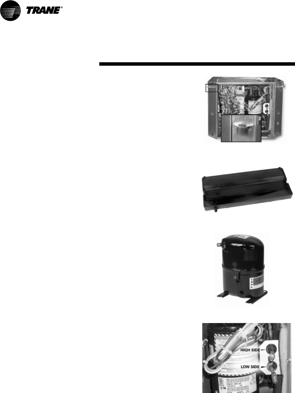
Schrader Connections
The connections for the low and high
side of the refrigeration system are lo-
cated directly beside the control box at
the front, service access panel. See
Figure 8 for schrader connection lo-
tion.
Features and
Benefits
Figure 5: Hanging bracket design
Figure 6: Plastic drain pan
Figure 7: Reciprocating compressor
Figure 8: Schrader connections
WSHP-PRC001-EN 7
Figure 9: Coaxial water coil
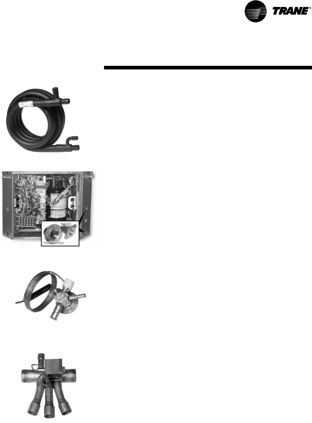
Figure 10: Water connection device
Figure 11: Thermal expansion valve
Figure 12: Reversing valve
Co-axial Water-to-Refrigerant Coil
The unit’s internal heat exchanging
water coil is engineered for maximum
heat transfer.
The copper or cupro-nickel seamless
tubing is a tube within a tube design.
The inner-water tube contains a deep
fluted curve to enhance heat transfer
and minimize fouling and scaling. It is
available in either copper or cu-
pro-nickel (selectable option) coil.The
outer refrigerant gas tube is made
from steel material. The coil is leak
tested to assure there is no cross leak-
age between the water tube and the
refrigerant gas (steel tube) coil. Co-ax-
ial heat exchangers are more tolerant
to freeze rupture. See Figure 9 for
co-axial water coil.
Compressor and Co-axial Coil
Isolation
Vibration isolation of the compressor
and co-axial water coil is accom-
plished by increasing the rigidity and
stiffness at the base. The platform pro-
vides double isolation to the compres-
sor and single isolation to the co-axial
water coil for additional attenuation
during compressor start and stop.
Water Connections
The water-in/water-out connections to
the co-axial water coil are located on
the right-hand chamfered corner of
the unit. The fittings are mounted flush
to the chamfered wall to help limit
shipping damage.
The water connection devices are con-
structed of copper or bronze material
and include a National Female Pipe
Thread (NFPT) junction. The connec-
tions are attached to the unit’s cham-
fer corner to alleviate the need for a
back-up wrench during installation.
See Figure 10 for water connection de-
vice.
Expansion Valve
All Trane water-source systems in-
clude an expansion valve flow meter-
ing device.
This thermal expansion valve (TXV) al-
lows the unit to operate with an enter-
ing fluid temperature from 25 F to 110
F, and entering air temperatures from
40 F to 90 F. The valve is designed to
meter refrigerant flow through the cir-
cuitry to achieve desired heating or
cooling.
The expansion valve device allows the
exact amount of refrigerant required
to meet the coil load demands. This
precise metering by the TXV increases
the efficiency of the unit. See Figure 11
for thermal expansion valve.
Reversing Valve
A system reversing valve (4-way
valve) is included with all heating/
cooling units. This valve is piped to be
energized in the cooling mode to allow
the system to provide heat if valve fail-
ure were to occur. Once the valve is
energized for cooling, it will remain
energized until the control system is
turned to the OFF position, or a heat-
ing cycle is initiated.
Units with the cooling only option will
not receive a reversing valve. See Fig-
ure 12 for reversing valve.
Features and
Benefits
8WSHP-PRC001-EN
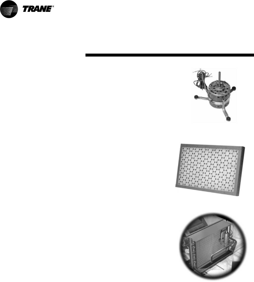
Blower Motor
The supply-air (blower) motor is a
multi-speed motor with internal ther-
mal overload protection. The motor
bearings are permanently lubricated
and sealed. Standard motors are rated
from .20 ESP. Optional high static mo-
tors are rated from .40 to 1.40 ESP. All
motors are factory wired to the option
selected. A high, medium, and low
speed tap is provided for field custom-
ization on most voltages. The speed
tap modification can be made in the
control box of the unit. See Figure 13
for blower motor.
Note: The 380, 415, 460 and 575 volt
designs are provided in a dual or
three-speed version only. See fan per-
formance section for factory ratings
(Page 66).
Serviceability to the motor is made
through either of the two air-side ac-
cess doors for the horizontal configu-
ration, and through one air-side
access door on vertical configuration.
The motor and blower wheel are re-
movable by an orifice ring mounted to
the fan housing.
Blower Housing
The blower housing is constructed of
non-corrosive galvanized steel. A fac-
tory-mounted orifice ring is provided
for ease of motor serviceability on the
1/2 through 5-ton direct drive units.
All air-side panels are interchangeable
with one another for ease of field con-
vertibility of the supply-air on the GEH
model.
Air-Side Filter
The air-side filter incorporates a 1-inch
thick (nominal) or 2-inch thick (nomi-
nal) disposable fiberglass option.
These filters include an average syn-
thetic dust weight arrestance of ap-
proximately 75%. This dust holding
capability includes a colorless, odor-
less adhesive to retain dirt particles
within the filter media after fiber con-
tact. See Figure 14 for filter media.
Air-to-Refrigerant Coil
The air-to-refrigerant heat exchanger
is constructed of staggered copper
tubes with die-formed corrugated
lanced aluminum fins. The fins are
then mechanically bonded to the
tubes through expansion.
The coil is placed internal of the unit
design for the GEH model to provides
an optional dual filtration application.
With dual filtration to the GEH unit,
maintenance to the filter is significant-
ly less than with a single filtration sys-
tem. This design also offers maximum
flexiblity of the supply and return air
configurations.
The maximum working pressure for
both the GEH and GEV coils is 450
psig. It is designed for maximum ca-
pacity with an additional benefit of
physical unit size reduction.
Coil specifications for both GEH and
GEV models may be found on in the
General Data section on page 36 of
this catalog. See Figure 15 for internal
air to refrigerant coil placement.
Features and
Benefits
Figure 13: Blower motor (direct drive)
Figure 14: Filter media
Figure 15: Internal air-to-refrigerant
coil placement (model GEH)
WSHP-PRC001-EN 9
Sound Attenuation Package
Testing of conventional units has iden-
tified that the sound radiated by the
casing of the unit is an important com-
ponent of the sound that reaches occu-
pants, especially when the unit is
located directly over the occupied
space.
This sound reduction package reduces
radiated noise from the cabinet. Trane
double-isolates the compressor and
single-isolates the co-axial coil in the
unit. This design absorbs the vibration
that contributes to radiated sound
For sound critical spaces, an
enhanced sound package as described
in Table 1 provides additional attenua-
tion.
Complete sound data taken in accor-
dance with ARI 260 is available for all
units. The test data reflects
multi-speed fan motor along a single
system curve.
Dual Filtration
Flexibility of the GEH allows for dual
filtration in a free return application.
With the field installed dual filtration
accessory, filter maintenance of the
unit is significantly less.
The accessory package includes both
the bottom and top filter rack, and
one, 1-inch or 2-inch filter. Table 2
provides dual filtration accessory
numbers appropriate to unit size.
Table 2: Dual filter accessory kit
numbers
Unit Size
1-inch
Filter
1-inch
Filter Kit Part
No.
2-inch
Filter Kit Part
No.
006-015 4474 0630 0100 4474 0634 0100
018-030 4474 0631 0100 4474 0635 0100
036, 042 4474 0632 0100 4474 0636 0100
048, 060 4474 0633 0100 4474 0637 0100
Features and
Benefits
The sound package for the horizontal unit includes:
Table 1: Sound Package (GEH units ONLY)
Enhanced Sound Attenuation
Package (Standard)
Deluxe Sound Attenuation
Package (Option)
18-gauge compressor enclosure 16-gauge compressor enclosure
18-gauge single wall front panel 16-gauge single wall front panel
lined compressor enclosure with
1/2-inch cabinet insulation
lined compressor enclosure with
1/2-inch cabinet insulation
compressor discharge muffler compressor discharge muffler
12-gauge compressor/water-to-refrig-
erant heat exchanger pan with second
stage of vibration isolation
12-gauge compressor/water-to-refrig-
erant heat exchanger pan with second
stage of vibration isolation
compressor vibration isolation compressor vibration isolation
water-to-refrigerant heat exchanger
vibration isolation
water-to-refrigerant heat exchanger
vibration isolation
lengthwise unit base stiffeners lengthwise unit base stiffeners
3/32-inch foam gasket sealant placed
around the compressor and end panel
perimeter
Figure 16: Dual filtration accessory
10 WSHP-PRC001-EN
Boilerless Control/Electric Heat
(option)
In cooling dominant regions where
heat may be used 15 to 30 days out of
the winter season, eliminating the
boiler may be an economical advan-
tage to the building owner. Eliminat-
ing a boiler from the system reduces
costs associated with the mechanical
system installation, as well as the
maintenance and service of the boiler.
How can heat be provided for the few
days of the year when heat is neces-
sary? Through the water-source heat
pump of course. The advantage of the
water-source heat pump is it’s ability
to provide heat recovery within the
closed water-loop. While some
WSHPs may be extracting heat from
the closed water loop, other WSHPs
may be adding heat to the closed
water loop. This creates a perfect sys-
tem balance for heat sharing or move-
ment from one space to another.
But when water temperatures fall in a
boilerless system, and no further heat
recovery may be made via the closed
loop, heat may be added to the space
through a boilerless control electric
heat option. See Figure 17 for the boil-
erless control, electric heat system
diagram.
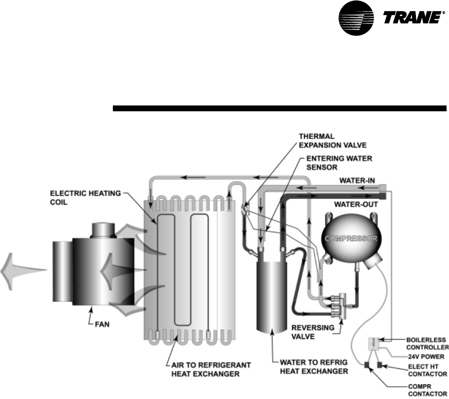
With the boilerless electric heat
option, the heat pump encompasses
an internal nichrome open wire heat-
ing element (factory mounted and
wired). It is comprised of a single
stage of electric heat designed to
invoice an electric heater in place of
the compressor in the event entering
water temperature falls below 55 F or
a field adjusted temperature setting
between 25 F to 60 F.
Features and
Benefits
Figure 17: Boilerless control, electric heat system
What is NOT available with the boilerless electric heat option?
1 Hot gas reheat
2 Basic 24 volt controls
3 TracerTM ZN510 controls
4 115 and 575 volt ratings
5 Supplemental or emergency heat applications
WSHP-PRC001-EN 11
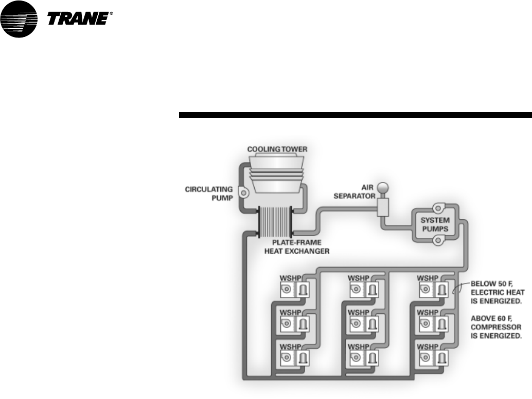
Boilerless Control/Electric Heat
Heating/Cooling Mode
In heating mode, when the water tem-
perature falls below 55 F (factory set-
ting), the electric heater
is energized, locking
out the compressor.
The systems electric
heat source will continue to be
utilized for primary
heating until
the loop
tempera-
ture rises
above 60 F.
Once the
entering water tempera-
ture rises above 60 F, the boiler-
less controller returns the unit to
normal compressor heating opera-
tion and locks out the electric heater.
This maximizes efficiency from the
unit during the few days requiring
heat from the mechanical system. See
Figure 18 for the factory mounted and
wired boilerless control electric heat
water-source heat pump. Available as
a single point power connection.
If the unit employs a cooling only unit
design, the electric heat contactor is
wired directly to the thermostat for
primary heating, and the compressor
contactor for cooling.
Note: For geothermal applications,
the boilerless controller has an adjust-
able setting of 25, 35, 45, 55 and 60
degrees.
Features and
Benefits
Figure 18: Boilerless control, electric heat water-source heat pump
12 WSHP-PRC001-EN
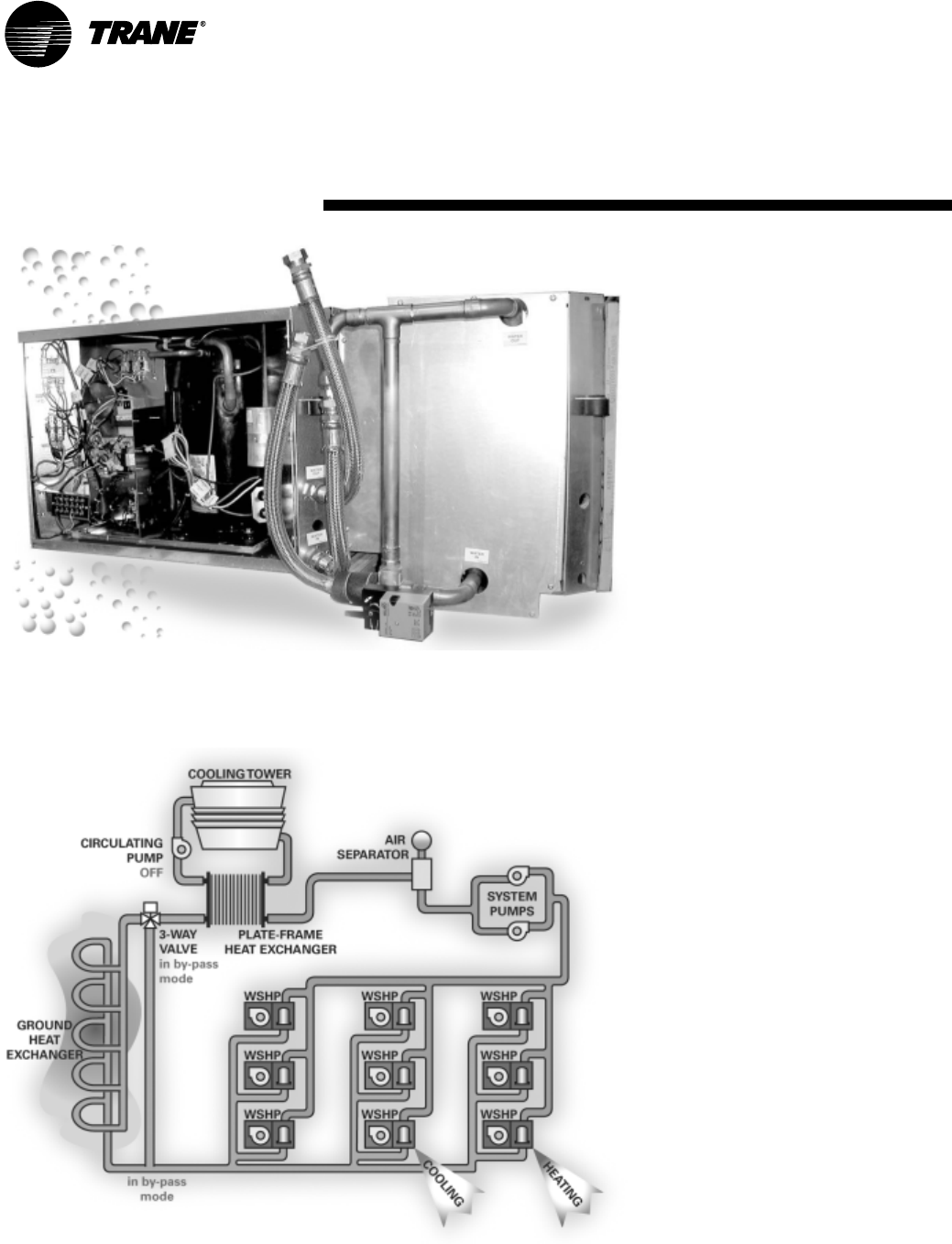
Waterside Economizer (option)
The beauty of the waterside economiz-
er is it’s ability to take advantage of
any loop condition that results in cool
water temperatures. A prime example
would be during fall, winter and spring
when cooling towers have more ca-
pacity than required and could be con-
trolled to lower temperatures for
economizer support.
Another more common inexpensive
means of free comfort cooling in-
cludes buildings systems where pe-
rimeter heating and core cooling are
needed. In this system, the perimeter
units extract heat from the building
loop while in the heating mode, forc-
ing the building loop temperature to
drop. Where as, the core are of a build-
ing may require cooling in summer or
in winter based upon lighting, people
and equipment.
If the water-source system design con-
tained an economizing coil option, the
moderate temperature loop water cir-
culated through a core water-source
system can provide an inexpensive
means to satisfy room comfort with-
out operating the water-source heat
pump’s compressor.
During economizer mode, fluid enters
the unit, and passes by a water tem-
perature sensing bulb. This tempera-
ture sensing bulb determines whether
the two position, three-way valve will
direct the water through the waterside
economizing coil, and to the heat
pump condenser, or through the con-
denser only. If the water temperature
is 55 F or less, fluid will flow into the
economizing coil, while simultaneous-
ly halting mechanical operation of the
compressor. Mechanical cooling will
continue on a call for second stage
from the thermostat.
The factory built waterside economiz-
er is available on all 1/2 to 5 ton GEH
models.The 1/2 through 5-ton GEV
may be ordered to accept a field pro-
vided waterside economizing pack-
age.
Features and
Benefits
Figure 19: Model GEH with waterside economizer package
Figure 20: Waterside economizer system
Note: Condensate overflow is not available with
the waterside economizer option.
WSHP-PRC001-EN 13
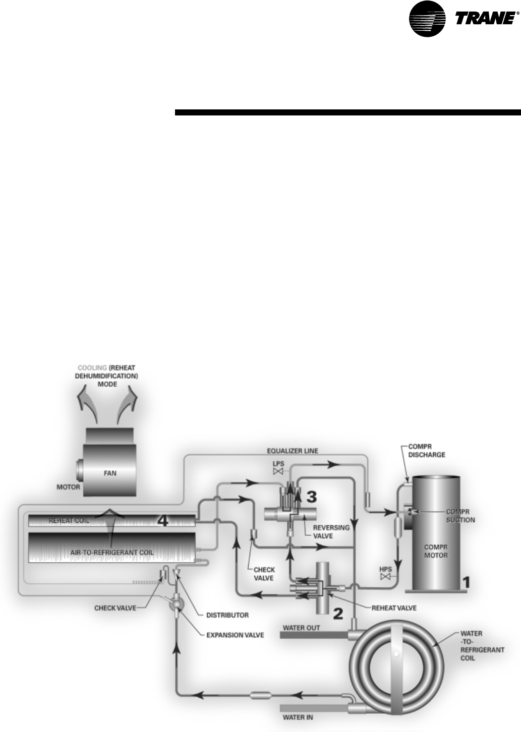
Hot Gas Reheat (option)
For space conditioning and climate
control, Trane provides an accurate
and cost effective dehumidification
control through a hot gas reheat op-
tion. This option is designed to accom-
modate unit sizes 012, 036, 048, and
060
With this reheat option, the return air
from the space is conditioned by the
air-to-refrigerant coil, then reheated
by the reheat coil to control not only
the space temperature, but to also re-
duce the relative humidity of the
space. The moisture removal capabili-
ty of a specific heat pump is deter-
mined by the units latent capacity
rating.
When operating in the reheat mode
(meaning the sensible temperature
has been met in the space), the humi-
distat signals the reheat relay coil to
energize, allowing the high pressure
refrigerant gas to flow from the (1)
compressor, through the (2) reheat
valve, into the (3) reversing valve, or
through the (4) reheat coil for dehu-
midification. A switching relay has
been provided for the reheat applica-
tion to adjust the blower motor from
normal operation to low speed when
hot gas reheat is energized.
Note: Trane places an air separation
space between the air-to-refrigerant
coil, and the reheat coil to allow for
maximum moisture removal.
Common Reheat Applications
The hot gas reheat option is designed
to support building applications re-
quiring fresh-air ventilation units de-
livering unconditioned-air directly to
the space. It also provides dehumidifi-
cation to large latent load spaces such
as auditoriums, theaters and class-
rooms, or anywhere humidity control
is a problem.
Do’s and Don’ts in Design
The factory installed hot gas reheat
option is only available with Deluxe or
ZN524 controls packages.
A high static blower motor option will
be required to support the hot gas re-
heat option for the 1/2 through 5 ton
equipment.
Water regulating valves should not be
used with the hot gas reheat option.
Trane places a thermal expansion
valve on all water-source heat pumps,
as well as ground-source heat pumps,
to regulate refrigerant flow vs. water
flow, making the heat pump more effi-
cient to run.
Water-source heat pumps with hot gas
reheat should not be used as a
make-up air unit.
Features and
Benefits
Figure 21: Hot gas reheat heat pump
14 WSHP-PRC001-EN
Features and Benefits
Controls
Controls by Trane
Whether involved in a retrofit or new construction application, Trane has the control design to fit your system requirement.
Our control options provide a broad range of packages from the most cost efficient 24 volt standalone to a complete build-
ing automation solution, Trane is the right choice in comfort gratification. The following chart provides a brief overview in
the different control combinations.
HGR = Hot Gas Reheat
WSE = Waterside Economizer
BEH = Boilerless Electric Heat
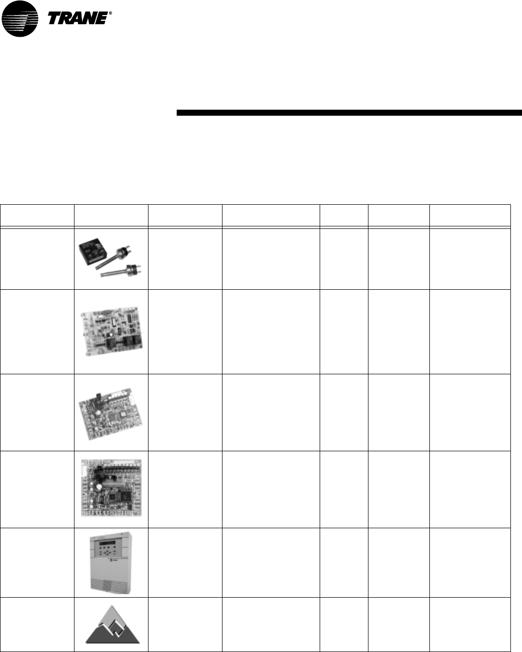
Graphic Description Application ICS Protocol Where to find
Basic 24V Compressor lock-
out relay, low and
high pressure
switches.
Retrofit market where sin-
gle and multiple unit
replacement occurs.
New building design where
field provided controls are
specified.
No Non Applicable Page 15
Deluxe 24V 24 volt micropro-
cessor designed to
provide control of
the entire unit, as
well as multiple
relay offerings to
maximize system
performance. Can
connect to a 24V
thermostat.
Retrofit market where sin-
gle and multiple unit
replacement occurs.
Multi-unit installation
where units may be daisy-
chained directly to the
Trane TracerTM Loop Con-
troller.
No Non Applicable Page 16
Tracer ZN510TM Direct Digital Con-
trol board designed
to provide control
of the entire unit as
well as outputs for
unit status and fault
detection.
Retrofit market where over-
all system upgrade is speci-
fied.
Multi-unit (100+) installa-
tion where units are linked
by a common twisted pair
of wire for a communica-
tion link.
Yes SCC LonTalk®
open protocol
(Comm5)
Page 18
Tracer ZN524TM
Used in
single circuited
WSHPs with HGR,
WSE, or BEH.
Direct Digital Con-
trol board designed
to provide control
of the entire unit as
well as outputs for
unit status and fault
detection.
Retrofit market where over-
all system upgrade is speci-
fied.
Multi-unit (100+) installa-
tion where units are linked
by a common twisted pair
of wire for a communica-
tion link.
Yes SCC LonTalk
open protocol
(Comm5)
Page 18
TracerTM Loop
Controller
Microproces-
sor-based control-
ler that coordinates
the water side
(boiler, pumps,
cooling tower, etc.)
of a water-source
heat pump system.
Wherever the Tracer ZN510
controls or 24 volt elec-
tro-mechanical
controls are specified for
complete control of the
water loop and pumps.
Yes LonTalk
compatible
(Comm5)
WSHP-MG-3
Tracer Summit®Microprocessor
based controller
that coordinates full
building automa-
tion from HVAC to
lighting.
Where any controller is
specified.
Yes BAC net
(Comm 2,3,4,5)
EMTW-SVN01B-EN
EMTW-SVP01B-EN
EMTW-SVU01B-EN
WSHP-PRC001-EN 15
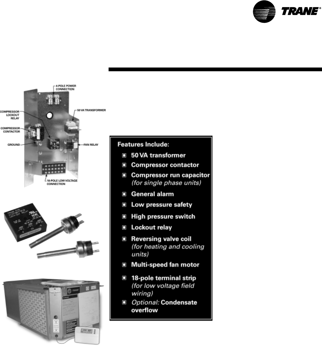
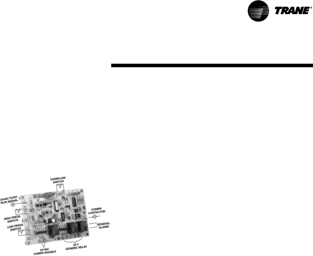
Basic 24 Volt Controls
The basic 24 V electro-
mechanical unit control provides com-
ponent protection devices for maxi-
mum system reliability. Each device is
factory mounted, wired and tested.
See Figure 22 for the unit control box.
Safety Devices
System safety devices are provided
through the use of low/high pressure
switches in the refrigeration circuit to
help prevent compressor damage.
The switch and sensor are set to acti-
vate at refrigerant pressures of 20 psig
to fit most applications.
In cases where a low charge, or exces-
sive loss of charge occurs, each com-
pressor comes equipped with an
external overload device to halt the
compressor operation.
The high pressure switch prevents
compressor operation during high or
excessive discharge pressures that ex-
ceed 395 psig.
A lockout relay provides the mechani-
cal communication of the low and high
pressure switches to prevent com-
pressor operation if the unit is under
low or high refrigerant circuit pres-
sure, or during a condensate overflow
condition. The lockout relay may be re-
set at the thermostat, or by cycling
power to the unit.
General alarm is accomplished
through the lockout relay and is used
in driving light emitting diodes. This
feature will drive dry contacts only,
and cannot be used to drive field in-
stalled control inputs.
See Figure 23 for unit safety devices
on the basic 24V control unit.
Stand-alone System
The 24 volt electro-mechanical design
may be applied as a stand-alone
control system. The stand-alone
design provides accurate temperature
control directly through a
wall-mounted mercury bulb or
electronic thermostat. This system
set-up may be utilized in a
replacement design where a single
unit retrofit is needed. It may be easily
interfaced with a field provided control
system by way of the factory installed
18-pole terminal strip.
This stand-alone control is frequently
utilized on small jobs where a building
controller may not be necessary, or
where field installed direct digital
controls are specified. This type of
control design does require a constant
flow of water to the water source heat
pump. With a positive way to sense
flow to the unit, the units safety
devices will trigger the unit off.
The stand-alone system design
provides a low cost option of
installation while still allowing room
control for each unit. See Figure 24 for
24 volt stand-alone system controls.
Features and Benefits
Basic Controls
Figure 22: Basic 24 volt control box
Figure 23: Safety devices
Figure 24: 24 volt stand-alone system
16 WSHP-PRC001-EN
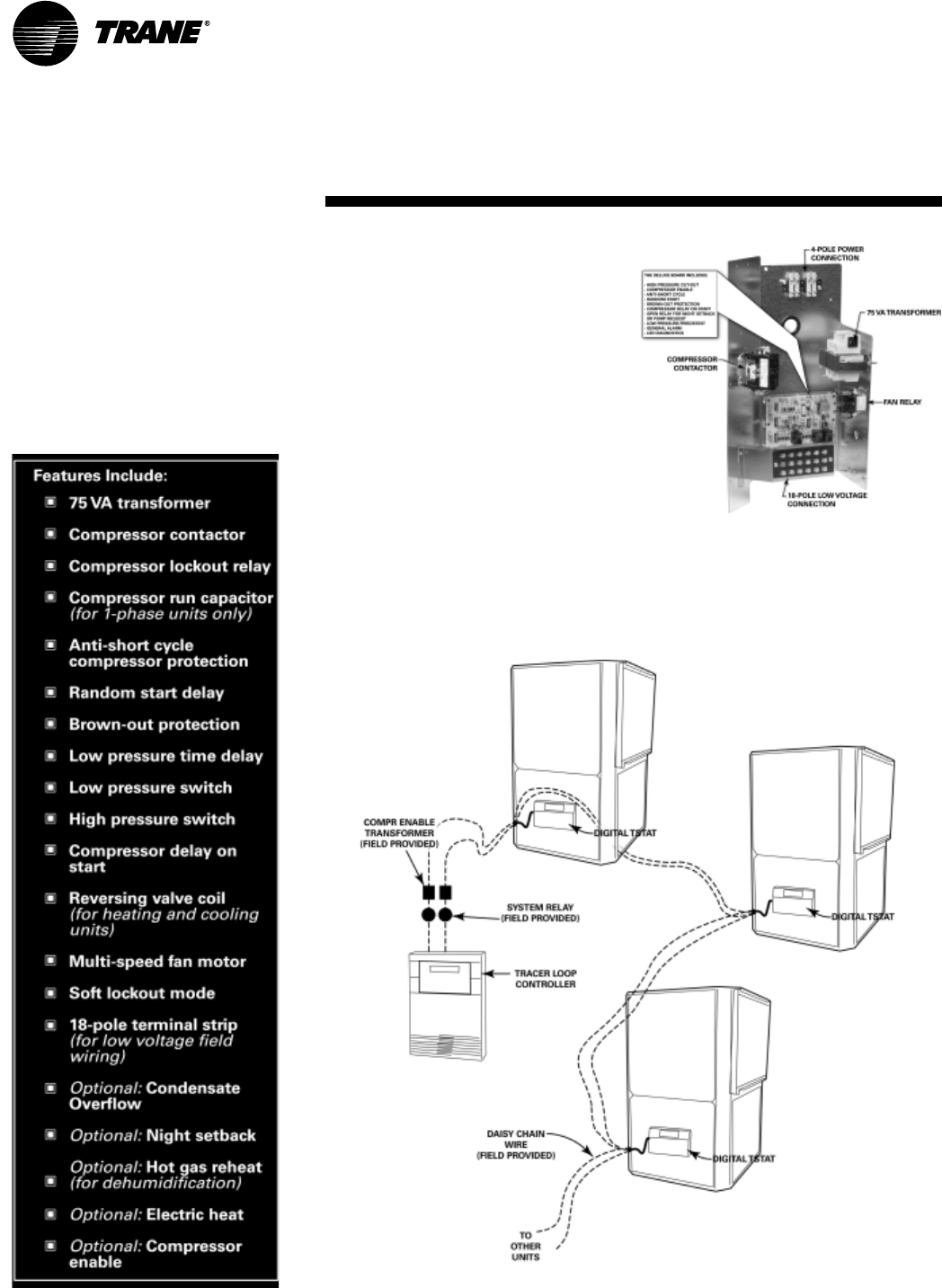
Deluxe 24V Electronic Controls
The deluxe 24V electronic unit control
provides component protection
devices similar to the basic design, but
contains upgraded features to
maximize system performance to
extend the system life. Each device, is
factory mounted, wired, and tested in
the unit. See Figure 25 for unit control
box.
Small Building Control
The deluxe 24V electro-mechanical
design may be applied as a
stand-alone control system or as a
multi-unit installation system. With a
stand-alone design, units run
independently of one another with a
mercury bulb or electronic digital
thermostat.
With a multiple unit installation, the
units may be daisy-chained directly to
the Trane Tracer loop controller (TLC),
pump(s), boiler, and tower for a
complete networked water-source
system. The TLC provides a night
setback output, and a pump request
input for system optimization.See
Figure 26 for 24 volt deluxe control
system.
Features and Benefits
Deluxe Controls
Figure 25: Deluxe 24 volt control box
Figure 26: 24 volt deluxe control system
WSHP-PRC001-EN 17
Microprocessor Design
The 24 volt deluxe design is a
microprocessor-based control board
conveniently located in the control
box. The board is unique to Trane
water-source products and is
designed to control the unit as well as
provide outputs for unit status and
fault detection.
The Trane microprocessor board is
factory wired to a terminal strip to
provide all necessary terminals for
field connections. See Figure 27 for
the deluxe 24V control board.
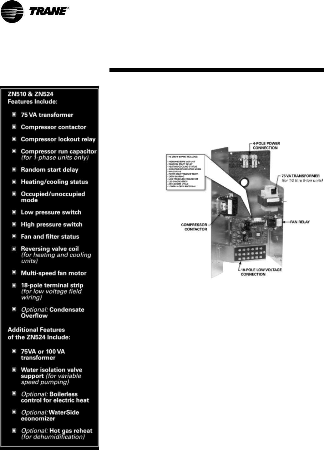
Deluxe 24V features include:
Random Start
The random start relay provides a time
delay start-up of the compressor when
cycling in the occupied mode. A new
start delay time between 3 and 10
seconds is applied each time power is
enabled to the unit.
Anti-short Cycle Timer
The anti-short cycle timer provides a
three minute time delay between
compressor stop and compressor
restart.
Brown-out Protection
The brown-out protection function
measures the input voltage to the
controller and halts the compressor
operation. Once a brown-out situation
has occurred, the anti-short cycle
timer will become energized. The
general fault contact will not be
affected by this condition. The voltage
will continue to be monitored until the
voltage increases. The compressors
will be enabled at this time if all
start-up time delays have expired, and
all safeties have been satisfied.
Compressor Disable
The compressor disable relay pro-
vides a temporary disable in compres-
sor operation. The signal would be
provided from a water loop controller
in the system. It would disable the
compressor because of low water
flow, peak limiting or if the unit goes
into an unoccupied state. Once the
compressor has been disabled, the an-
ti-short cycle time period will begin.
Once the compressor disable signal is
no longer present, and all safeties are
satisfied, the control will allow the
compressor to restart.
Generic Relay
The generic relay is provided for field
use. Night setback or pump restart are
two options that may be wired to the
available relay. (Note: Night setback is
available as factory wired). An exter-
nal Class II 24VAC signal will energize
the relay coil on terminals R1 and R2.
Terminals C (common), NO (normally
open), and NC (normally closed) will
be provided for the relay contacts.
Safety Control
The deluxe microprocessor receives
separate input signals from the refrig-
erant high pressure switch, low suc-
tion pressure switch and condensate
overflow.
In a high pressure situation, the com-
pressor contactor is de-energized,
which suspends compressor opera-
tion. The control will go into soft lock-
out mode initializing a three minute
time delay and a random start of 3 to
10 second time delays. Once these de-
lays have expired, the unit will be al-
lowed to run. If a high pressure
situation occurs within one hour of the
first situation, the control will be
placed into a manual lockout mode,
halting compressor operation, and ini-
tiating the general alarm.
In a low temperature situation, the low
pressure switch will transition open
after the compressor starts. If the
switch is open for 45 seconds during
compressor start, the unit will go into
soft lockout mode initializing a three
minute time delay and a random start
of 3 to 10 second time delays. Once
these delays have expired, the unit will
be allowed to run. If the low pressure
situation occurs again within 30 min-
utes, and the device is open for more
than 45 seconds, the control will be
placed into a manual lockout mode,
halting compressor operation, and ini-
tiating the general alarm.
In a condensate overflow
situation, the control will go into man-
ual lockout mode, halting compressor
operation, and initiating the general
alarm.
The general alarm is initiated when the
control goes into a manual lockout
mode for either high pressure, low
pressure or condensate overflow con-
ditions.
Diagnostics
Component device connections to the
microprocessor board are referenced
in Figure 27. Three LEDs (light emitting
diodes) are provided for indicating the
operating mode of the controller. See
the unit IOM for diagnostics or trouble-
shooting through the use of the LEDs.
Features and Benefits
Deluxe Controls
Figure 27: Deluxe 24V control board
18 WSHP-PRC001-EN
Tracer ZN510 & ZN524 Controls
The Tracer ZN510 and ZN524 are di-
rect digital control (DDC) systems spe-
cifically designed for single and dual
circuited water-source equipment to
provide control of the entire unit, as
well as outputs for unit status and fault
detection. Each de-
vice is factory in-
stalled,
commissioned,
and tested to en-
sure the highest
level of quality in
unit design.
Each of the con-
troller’s features
and options were
selected to coordi-
nate with the unit
hardware to pro-
vide greater ener-
gy efficiency and
equipment safety
to prolong the
equipment life.
In addition to be-
ing factory config-
ured for control of
the unit fan, compressor and reversing
valve, the ZN510 and ZN524 control-
lers are designed to coordinate the wa-
terside of the water-source system
through the Tracer Loop Controller
(TLC). If applied in a peer-to-peer com-
munication environment, data be-
tween similar controllers may be
exchanged without requiring a build-
ing automation system.
By teaming the ZN510 and ZN524 with
the TLC, a low first-cost for the me-
chanical equipment, water loop, and
water pump optimization is provided
to the owner.
For owners who require a full building
integrated "open protocol" system,
The ZN510/ZN524/TLC application is
upgradable to support complete build-
ing control through Tracer Summit.
Because the ZN510 and ZN524 is Lon-
Talk certified, it is capable of working
with, and talking to other LonTalk cer-
tified controllers providing the build-
ing owner more choices, and the
design engineers more flexibility to
meet the challenges of building auto-
mation. See Figure 28 for ZN510 con-
trol box.
Features and Benefits
ZN510 & ZN524 Controls
Figure 28: ZN510 control box
WSHP-PRC001-EN 19
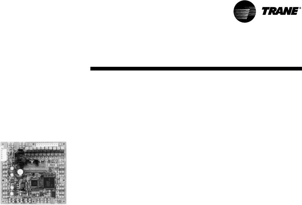
Direct Digital Controls
When the ZN510 or ZN524 controller is
linked directly to the Tracer Summit,
each Tracer Summit building
automation system can connect a
maximum of 120 Tracer ZN510 or
ZN524 controllers. See Figure 29 for
the Tracer ZN524 board.
Figure 29: Tracer ZN524 controller
Tracer ZN510 and ZN524
functions include:
Compressor Operation
The compressor is cycled on and off to
meet heating or cooling zone de-
mands. Single and dual compressor
units use the unit capacity and pulse
width modulation (PWM) logic along
with minimum on/off timers to deter-
mine the compressor’s operation. The
compressor is controlled ON for long-
er periods as capacity increases and
shorter periods as capacity decreases.
Random Start
To prevent all of the units in a building
from energizing major loads at the
same time, the controller observes a
random start from 0 to 25 seconds.
This timer halts the controller until the
random start time expires.
Reversing Valve Operation
For cooling, the reversing valve output
is energized simultaneously with the
compressor. It will remain energized
until the controller turns on the
compressor for heating. At this time,
the reversing valve moves to a
de-energized state. In the event of a
power failure or controller OFF
situation, the reversing valve output
will default to the heating
(de-energized) state.
Fan Operation
The supply air fan operates at the fac-
tory wired speed in the occupied or oc-
cupied standby mode. When switch is
set to AUTO, the fan is configured for
cycling ON with heating or cooling. In
heat mode, the fan will run for 30 sec-
onds beyond compressor shutdown in
both occupied and unoccupied mode.
Fan Run Timer
The controller’s filter status is based
on the unit fan’s cumulative run hours.
The controller compares the fan run
time against an adjustable fan run
hours limit and recommends unit
maintenance as required.
Data Sharing
The Tracer ZN510/ZN524 controller is
capable of sending or receiving data
(setpoints, fan request, or space tem-
perature) to and from other controllers
on the communication link. This al-
lows multiple units to share a common
space temperature sensor in both
stand-alone and building automation
applications.
Night Setback
The four operations of the Tracer
ZN510/ZN524 controller include occu-
pied, occupied standby, occupied by-
pass and unoccupied.
In an occupied situation, the con-
troller uses occupied heating and cool-
ing setpoints to provide heating and
cooling to the building. This occupied
operation is normally used during the
daytime hours when the building is at
the highest occupancy level.
In an occupied standby situation,
the controllers heating and cooling
setpoints are usually wider than the
occupied setpoints. This occupied
standby operation is used during day-
time hours when people are not
present in the space (such as lunch-
time or recess). To determine the
space occupancy, an occupancy sen-
sor is applied.
In an unoccupied situation, the con-
troller assumes the building is vacant,
which normally falls in evening hours
when a space may be empty. In the un-
occupied mode, the controller uses
the default unoccupied heating and
cooling setpoints stored in the control-
ler. When the building is in unoccupied
mode, individual units may be manu-
ally placed into timed override of the
unoccupied mode at the units wall
sensor. During timed override, the
controller interprets the request and
initiates the occupied setpoint opera-
tion, then reports the effective occu-
pancy mode as occupied bypass.
In the occupied bypass mode, the con-
troller applies the occupied heating
and cooling setpoint for a 120 minute
time limit.
High and Low Pressure
Safety Controls
The Tracer ZN510/ZN524 controller
detects the state of the high pressure
or low pressure switches. When a fault
is sensed by one of these switches, the
corresponding message is sent to the
controller to be logged into the fault
log. When the circuit returns to nor-
mal, the high pressure control and low
pressure control automatically reset. If
a second fault is detected within a thir-
ty-minute time span, the unit must be
manually reset.
Condensate Overflow
When condensate reaches the trip
point, a condensate overflow signal
generates a diagnostic which disables
the fan, unit water valves (if present),
and compressor. The unit will remain
in a halted state until the condensation
returns to a normal level. At this time,
the switch in the drain pan will auto-
matically reset. However, the control-
ler’s condensate overflow diagnostic
must be manually reset to clear the di-
agnostic and restart the unit.
Features and Benefits
ZN510 & ZN524 Controls

20 WSHP-PRC001-EN
Additional Functions of the
ZN524 Controller
When the building owners choice is
Trane Tracer controls, the ZN524 con-
troller is required when any of the fol-
lowing applications are selected on a
single and dual circuited equipment.
• Waterside Economizer
• Hot Gas Reheat
(for Dehumidification)
• Boilerless Control for Electric Heat
• Water Isolation Valve Control
(for Variable Speed Pumping)
Entering Water Temperature
Sampling
The ZN524 controller will sample the
entering water temperature to deter-
mine proper control action for units
equipped with boilerless electric heat
or waterside economizer.
Waterside Economizer: Entering
water temperature (EWT) sampling
will automatically occur at power up
when the unit is equipped with a wa-
terside economizer (WSE). The EWT is
used to determine if economizing is
feasible. When the conditions are met,
the isolation valve(s) are driven open
for three minutes and the EWT reading
is taken. The determination as to
whether or not the economizer can be
enabled will be made and the control-
ler will take appropriate action. The
isolation valve will remain open re-
gardless if the WSE or the DX cooling
is enabled.
The unit’s waterside economizer will
contain a 2-position water valve wired
to the ZN524. The economizing water
coil will be optimized to provide 100%
of the unit capacity at 80.6 F/66.2 F re-
turn air temperature with 45 F entering
water. The flow rate is established at
86 F entering water temperature and
96 F leaving water temperature.
Low leaving air protection will be fur-
nished to protect the unit against de-
livering air that is cold enough to
sweat discharge air grilles. Coil icing
protection will also be provided.
Waterside economizer cooling will be
active during occupied, unoccupied
and standby cooling modes.
Boilerless Control Electric Heat
and Supplemental Electric Heat:
The ZN524 supports a single stage of
boilerless electric heat operation or
concurrent heating.
When the unit is configured for boiler-
less control, the EWT will be used to
determine whether DX heating should
be disabled and the electric heater en-
abled. When these conditions are met,
the isolation valve(s) are driven open
for three minutes and the entering wa-
ter temperature reading is taken. The
determination as to whether or not to
utilize electric heat will be made and
the controller will take appropriate ac-
tion. If boilerless electric heat is en-
abled, then the isolation valve will be
closed, shutting down the water flow
to the unit.
When the unit is configured for con-
current operation of DX heating (com-
pressor in heat pump mode) and
electric heat, the electric heat will act
as a second stage of heat for single
compressor units, and a third stage of
heat for dual compressor units. Note:
With concurrent (or supplemental)
electric heat, the electric heater is field
provided.
Water Isolation Valves
Variable speed pumping systems are
supported by the ZN524 controller
when water isolation valves are
present. Up to two isolation valves are
supported by the controller (one for
each compressor circuit).
The valves are normally closed unless
DX heating, DX cooling, waterside
economizer or dehumidification is re-
quested. When the isolation valves are
driven open for operation, the outputs
will be driven for 20 seconds to ensure
adequate water flow before the com-
pressor outputs are energized. Once
an isolation valve has been opened, it
will remain open for a 10 minute mini-
mum to reduce excessive cycling of
the valve.
Dehumidification
Dehumidification for the single and
dual circuited water-source heat pump
is applicable with the ZN524 control-
ler. The controller is capable of direct-
ing one stage of DX cooling in
conjunction with one stage of reheat
(hot gas reheat).
Dehumidification can only occur when
the controller is in the cooling mode. A
humidity transmitter is used to mea-
sure the zone’s relative humidity (RH),
then compares the zone relative hu-
midity to the relative humidity enable/
disable setpoint parameters. The de-
fault values for dehumidification en-
able is 60% RH with the disable point
at 52% RH. These values are config-
urable.
Features and Benefits
ZN510 & ZN524 Controls
WSHP-PRC001-EN 21
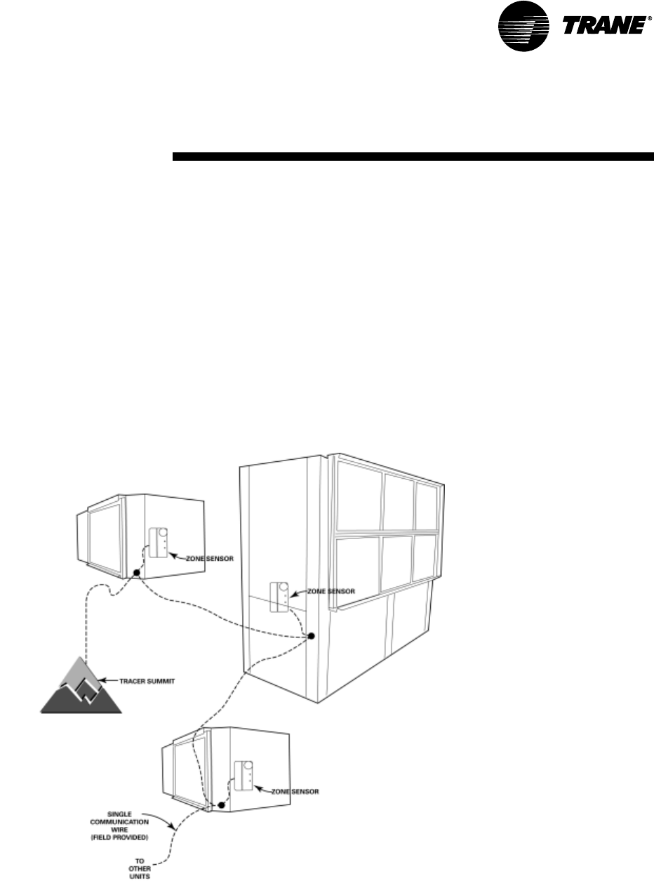
Building Control Advantages
The Tracer ZN510/ZN524 controller has the ability to share information with one
or several units on the same communication link. This sharing of information is
made possibe via a twisted pair of wire and a building automation system or
through Trane’s RoverTM service tool .
An advantage of installing a ZN510/ZN524 is its capability to work with other Lon-
Talk certified controllers. This provides greater flexibility to the building owner,
as well as greater flexibility in design.
Integrating the ZN510/ZN524 on water-source equipment, and tying it to a Tracer
Summit system provides a complete building management system. Each Tracer
Summit can connect to a maximum of 120 controllers. With the ICS system, the
Tracer can initiate an alarm on a loss of performance on equipment malfunctions;
allowing problems to be handled in a timely manner before compromising com-
fort.
This type of application would most commonly be used for a large space(s) that
may require more than one unit. In addition to
this application design, the Tracer
ZN510/ZN524 controller provides
a way for units located within the
same space to share the same
zone sensor to prevent units from
simultaneously heating and
cooling in the same space.See
Figure 30 for Tracer ZN510/ZN524
controller system.
Features and Benefits
ZN510 & ZN524 Controls
Figure 30: Tracer ZN510/ZN524 controller system
22 WSHP-PRC001-EN
Flexibility
The high efficiency vertical and hori-
zontal water-source heat pump sys-
tem is versatile for installation in
boiler/cooling tower applications, as
well as ground-source (geothermal)
applications. The system design may
employ either a central pumping de-
sign, or a distributed pumping design.
A central pumping design involves a
single pump design, usually located
within a basement or mechanical
room to fulfill pumping requirements
for the entire building system. An aux-
iliary pump is typically applied to less-
en the likelihood of system downtime
if the main pump malfunctions.
A distributed pumping system con-
tains a single pump module connected
directly to the units supply and return.
This module is field installed and
piped to the unit. This design requires
individual pump modules specifically
sized for each water-source heat
pump.
Advantages of Geothermal
The advantages of a geothermal heat
pump system could literally cut a busi-
ness’ heating and cooling costs by 30
to 40-percent. The units are durable,
and typically last longer than conven-
tional systems because they are pro-
tected from harsh outdoor weather
conditions, and because the unit is in-
stalled indoors and the loop under-
ground. (According to ASHRAE, the
estimated service life for a commercial
water-to-air heat pump is 19-years.)
Geothermal heat pumps have fewer
mechanical components, making
them more reliable and less prone to
failure. Manufacturers of the loop ma-
terials guarantee their products for up
to 25-years, with no maintenance re-
quired.
Geothermal heat pumps work toward
the preservation of the
environment by reducing the environ-
mental impacts of electric power gen-
eration.
A ground source (geothermal)
system consist of a:
• A ground water heat pump
• A closed loop ground heat ex-
changer made of high density
polyethylene pipe (guaranteed
25- years or more by many man-
ufacturers); and
• A low wattage circulating pump(s)
The fluctuating temperatures of fluid
from the earth are more stable than
air, allowing the equipment to operate
at a lower discharge pressure and use
fewer kilowatts. The constant earth
temperature will heat or cool the fluid
running through buried high density
polyethylene pipe to provide heating
and cooling to a building.
A geothermal loop can be installed ei-
ther horizontally or vertically. Vertical
loops require less overall land area to
reject (i.e., sink) the excess heat from
the building. Horizontal loops require
trenches in the ground spanning a
larger overall land area.
Although external piping is the re-
sponsibility of the installer and/or pip-
ing manufacturer, many electric
utilities and rural electric cooperatives
are offering monetary incentives to in-
stall geothermal systems. Utility com-
panies offer the incentives because of
reduced peak loads that flatten out
their demand curve over time, and
save them money. These savings are
ultimately transferred to the consum-
er. See Figure 31 for geothermal ener-
gy recovery loop.
Application
Considerations
Figure 31: Geothermal energy recovery loop
WSHP-PRC001-EN 23
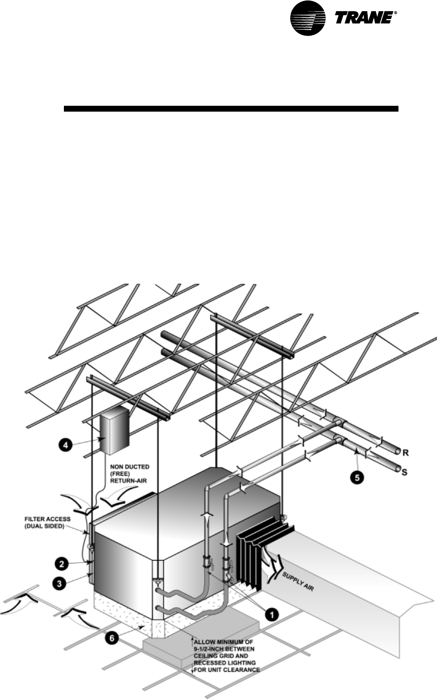
Central Pumping System
Units that employ a central pumping
system contain single or dual pumps
to fulfill pumping requirements for the
entire building system.
The central system’s supply and re-
turn lines should be sized to handle
the required flow with a minimum
pressure drop.
The water-source heat pump (in this
case a high efficiency GEH) may in-
clude add-on accessories to help aid in
system balancing, acoustics and safe-
ty requirements. Some of these items
may be ordered from the factory, then
field installed. Many are provided by
the contractor.
Hose kits are used to connect the
water supply and return line to the
water inlets and outlets. Trane of-
fers various hose kit combinations
to better facilitate system flow
balancing. These flexible
hoses also aid in the reduc-
tion of vibration between the
unit and the rigid central pip-
ing system.
A two position isolation valve is
often applied to systems which in-
corporate variable frequency
pumping. This valve is capable of
stopping/starting water flow to the
unit, which in-turn reduces the
pumping requirements for
the entire system.
The unit’s (item 2) 3/4-inch
high voltage and (item 3) 1/2-inch
low voltage connections are locat-
ed on the left chamfered corner
of the unit. They are de-
signed to accept con-
duit.
A field supplied line voltage dis-
connect should be installed for
branch circuit protection. Check
local codes for requirements.
The central system supply and re-
turn lines should be sized to han-
dle the required flow with a
minimum pressure drop.
Note: Pipe will sweat if low tem-
perature water is below the dew
point of the surrounding space.
Trane recommends that these
lines be insulated to prevent dam-
age from condensation when con-
denser loop is designed to be
below 60 F. Equipment installed in
attic/crawl space temperatures be-
low 40°F may require antifreeze in
the water loop.
For acoustically sensitive areas, a
six-inch deep fiberglass insulation
is recommended to be field in-
stalled below the horizontal unit.
This field supplied insulation
should be approximately twice the
footprint size of the unit. It pro-
vides sound damping of the unit
while in operation.
Application
Considerations
1
2
3
4
6
5
24 WSHP-PRC001-EN
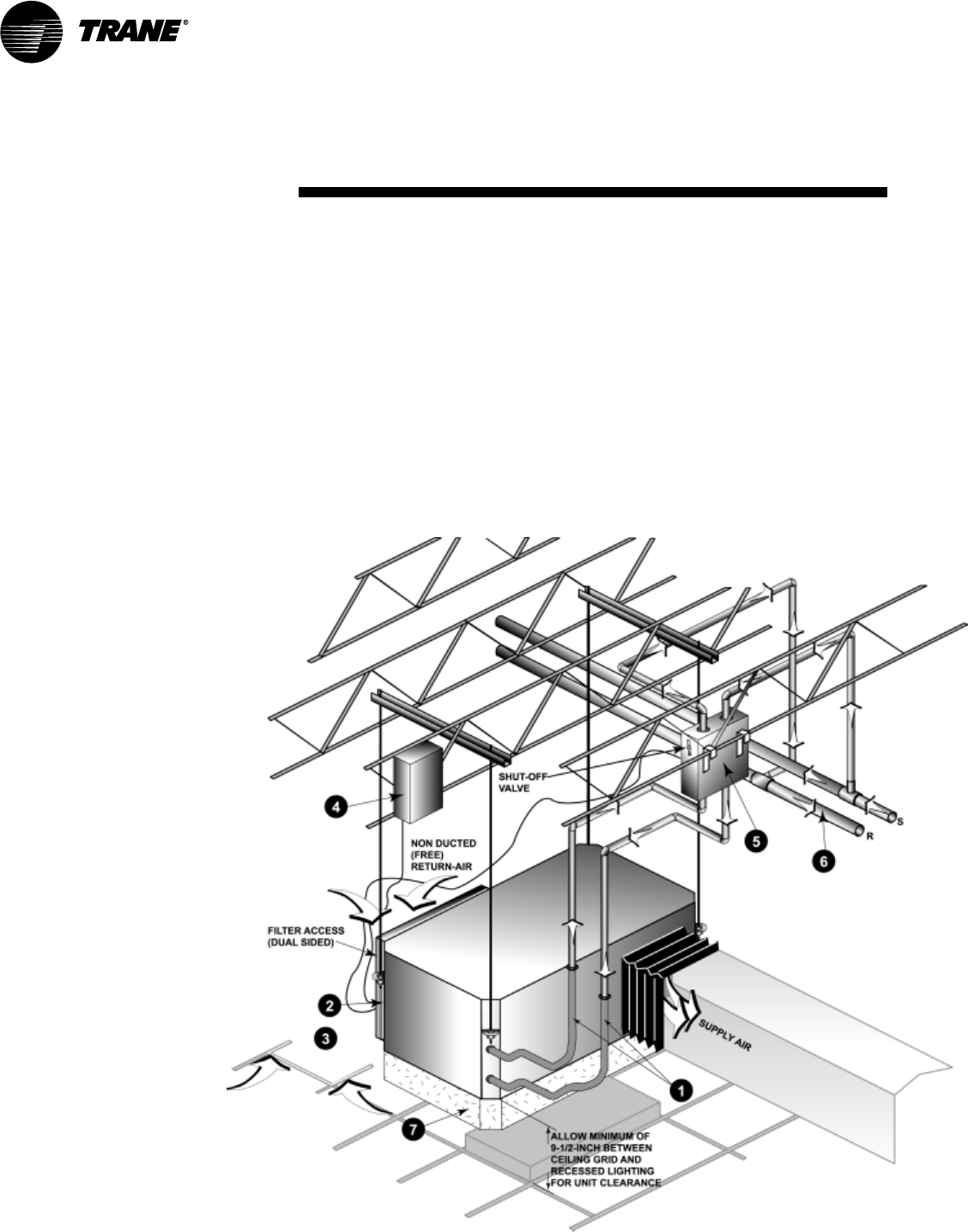
Distributed Pumping System
A distributed pumping system con-
tains either a single or dual pump
module, specifically sized for each wa-
ter-source heat pump, then connected
directly to the units supply and return
lines.
The distributed system’s supply and
return lines should be sized to handle
the required flow with a minimum
pressure drop.
Hose kits are used to connect the
water supply and return line to the
water inlets and outlets. Trane of-
fers various hose kit combinations
to better facilitate system flow bal-
ancing. These flexible hoses also
aid in the reduction of vibration be-
tween the unit and the rigid central
piping system.
The unit’s (item 2) 3/4-inch high
voltage and (item 3) 1/2-inch low
voltage connections are located
on the left chamfered corner of
the unit. They are designed to ac-
cept conduit.
A field supplied line voltage dis-
connect should be installed for
branch circuit protection. Check lo-
cal codes for requirements.
Trane’s self-contained pump mod-
ule and hose kit make a com-
plete pumping package for
distributed pumping systems.
The module is designed for circu-
lating commercial loops that re-
quire a maximum flow rate of 20
gpm. Each pump module is ful-
ly assembled for connec-
tion to water and electrical
points. The kit contains all
of the necessary compo-
nents for the installation, operation
and maintenance of a closed loop
application. See WSHPC-IN-5
(72-9006-03) for electrical and di-
mensional requirements
The distributed pumping system
supply and return lines should be
sized to handle the required flow
with a minimum pressure drop.
Note: Pipe will sweat if low tem-
perature water is below the dew
point of the surrounding space.
Trane recommends that these
lines be insulated to prevent dam-
age from condensation when con-
denser loop is designed to be
below 60 F. Equipment installed in
attic/crawl space temperatures be-
low 40°F may require antifreeze in
the water loop.
For acoustically sensitive areas, a
six-inch deep fiberglass insulation
is recommended to be field in-
stalled below the horizontal unit.
This field supplied insulation
should be approximately twice the
footprint size of the unit. It pro-
vides sound damping of the unit
while in operation.
Application
Considerations
1
2
3
4
5
67
WSHP-PRC001-EN 25
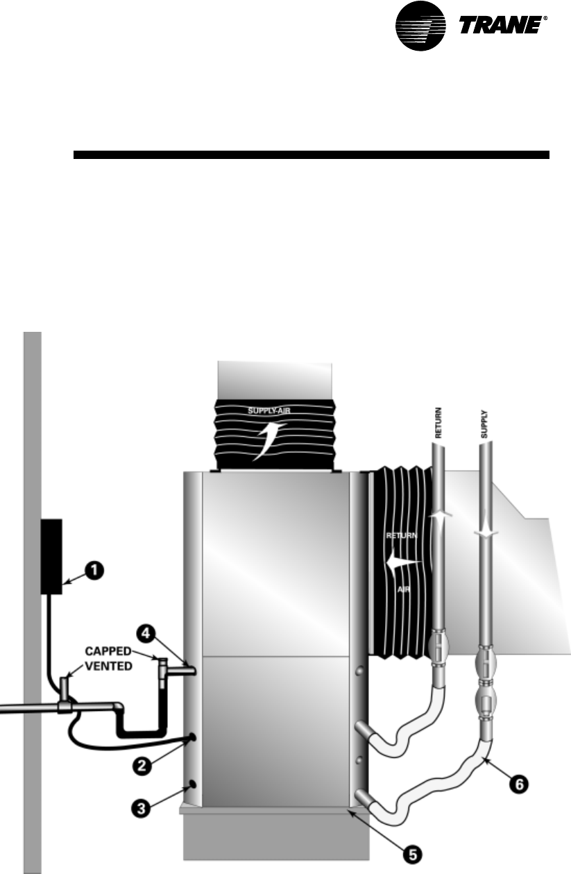
Installation of the 1/2 through
5-Ton Vertical
Whether securing the 1/2 through
5-ton GEV to a central pumping sys-
tem, or a distributed pumping system,
Trane recommends a few accessory
considerations to the system installa-
tion.
The field supplied line
voltage disconnect should
be installed for branch cir-
cuit protection.
The units (2) 3/4-inch high
voltage and (3) 1/2-inch
low voltage connections
are located on the left
chamfered corner of the
unit. They are designed to
accept conduit.
Trane recommends that
the condensate system be
set-up per negative pres-
sure trapping in consider-
ation of the unit’s
draw-through design.
With this properly trapped
system, when condensate
forms during normal oper-
ation, the water level in
the trap rises until there
is a constant outflow.
For acoustically sensitive areas, a
1/2-inch thick field provided vibra-
tion pad should be installed below
the vertical unit. This field provid-
ed piece should be equal to the
overall foot-print size of the unit to
provide sound damping of the
unit while in operation.
Hose kits are used to connect the
water supply and return lines to
the water inlet and outlets. Trane
includes various hose kit combi-
nations to better facilitate system
flow balancing. These flexible
hoses, reduce vibration between
the unit and the rigid piping sys-
tem.
Application
Considerations
1
2
4
3
56
26 WSHP-PRC001-EN
Installation Made Easy
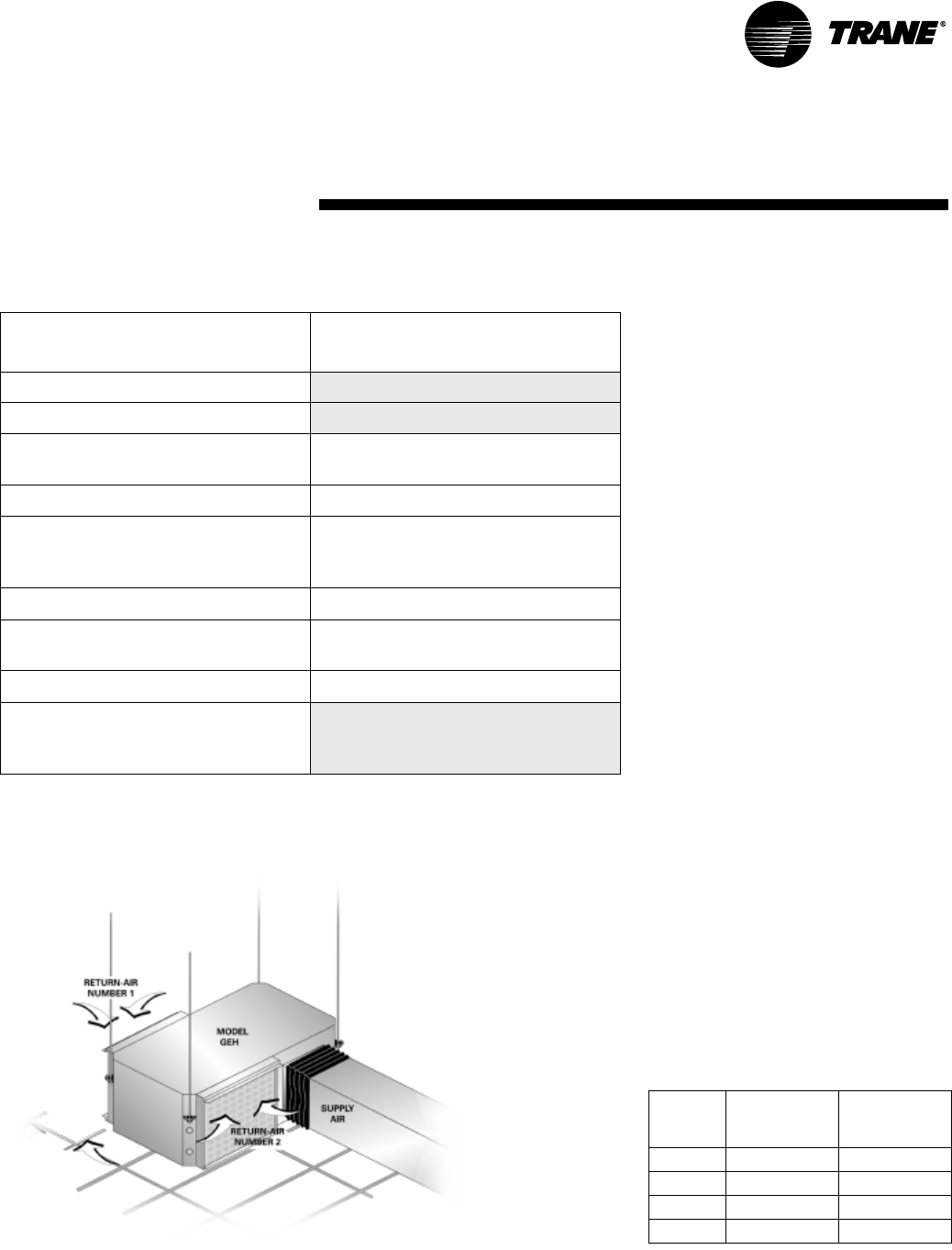
Installing a horizontal unit inside a corridor to enhance sound attenuation provides value to duct design. Trane takes this
fact one step further.
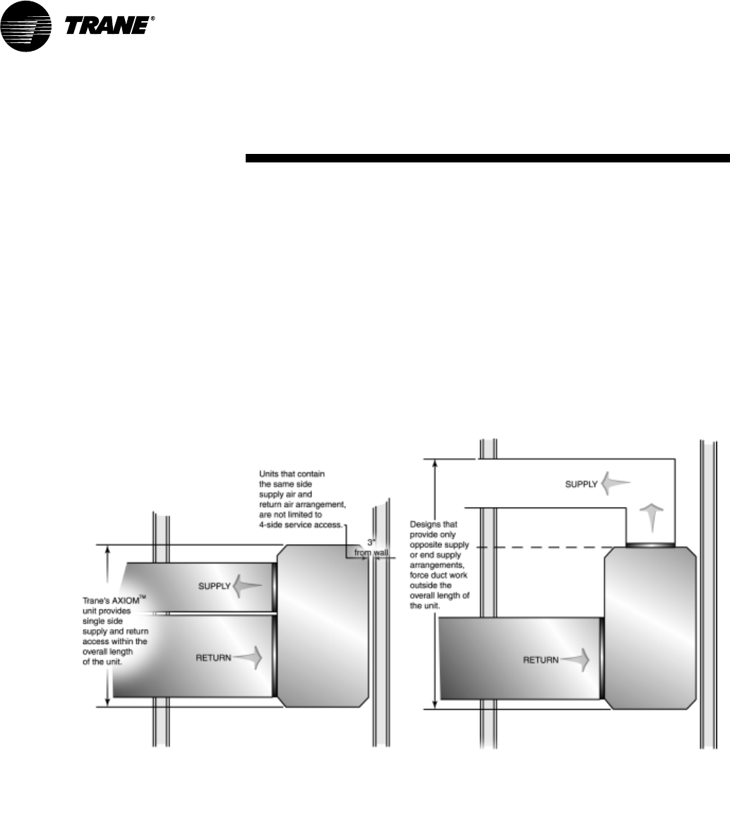
The new GEH design offers same side return-air/supply-air access to the unit. This access is contained within the overall
dimension of the units length as shown in Figure 32. The duct access to the unit allows the unit to be installed closely
against a corridor wall, while at the same time eliminating space required for the duct design.
Most horizontal unit designs provide an opposite supply air from the return air arrangement, or an end supply arrangement
option. See Figure 33 for end-supply example. An end-supply design increases the overall unit length of the system to ac-
commodate a 90-degree duct turn. This not only requires added space, but also adds cost in both materials and installation.
Additional value to the design is acquired through the same side supply/return-air design. This design eliminates a require-
ment for a four sided service access. When installing the same side return/supply-air access, a brief 3-inch minimum is all
that is required between the unit and the wall.
Application
Considerations
Figure 32: Same-side supply/return-air Figure 33: End supply arrangement/ductwork
WSHP-PRC001-EN 27
Duct Design for Noise Control
Proper acoustics are often a design
requirement. Most of the problems
that are associated with HVAC
generated sound can be
avoided by properly selecting
and locating the components
of the system. Acoustical
modeling should be used
to find the lowest cost
design to meet a
specific sound
requirement, however,
there are some general do’s
and don’ts that should be
observed.
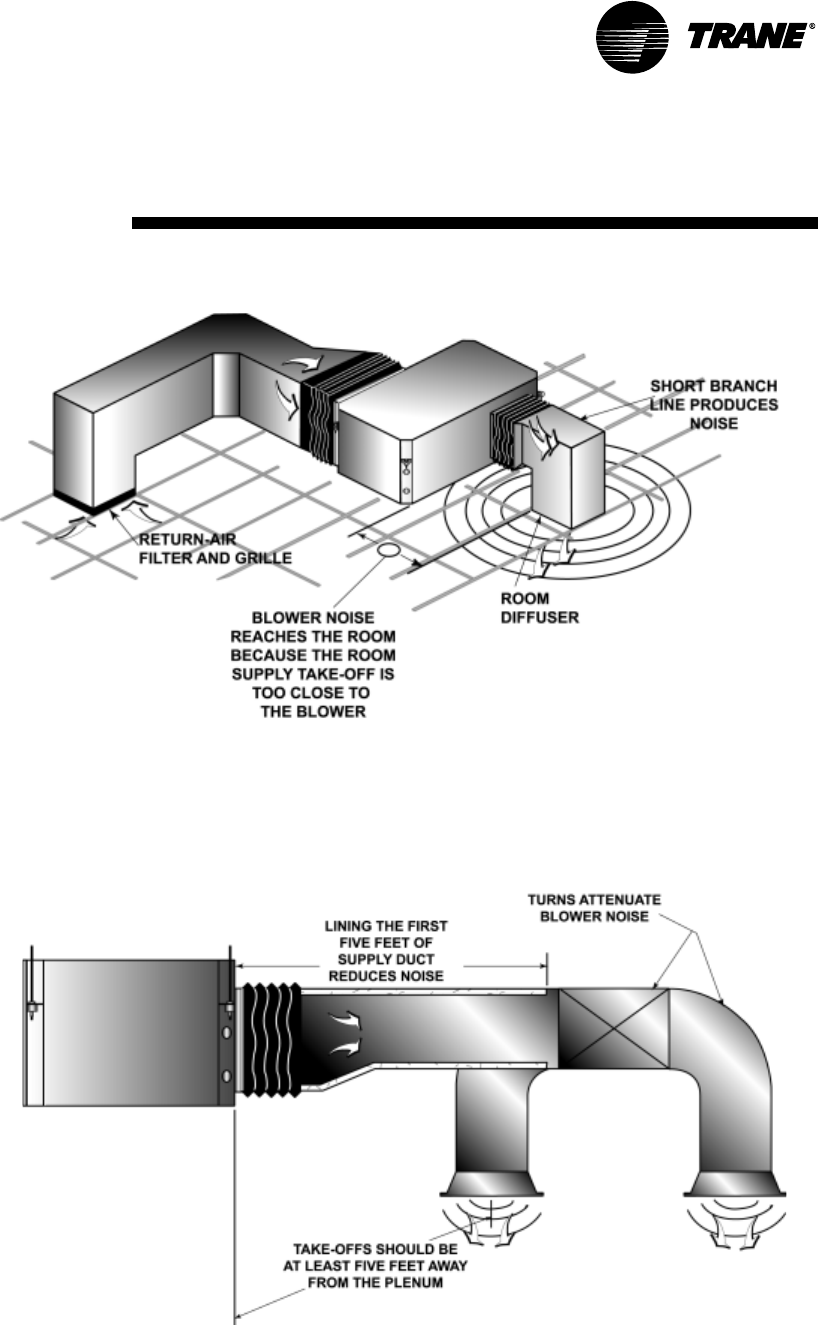
Figure 34 shows a supply air duct that
is placed too close to the blower to
provide substantial noise attenuation.
It also, represents the effects on sound
that a short supply branch connected
to the discharge may produce. Avoid
these forms of connections when
designing ductwork where noise
attenuation is critical.
The following suggestions will reduce
the amount of sound that reaches the
ocupied space:
• Design the duct run
with two 90-degree
turns
• Line the first 5 feet of
the supply trunk
• Line elbows and tran-
sition pieces, as well
as a short distance
upstream and downstream of the
fittings
• Use flexible connections to iso-
late vibrations
• Provide multiple discharges
• Keep duct velocity low
See Figure 35 for a positive represen-
tation of supply duct work design for
noise attenuation on units over 1 1/2
tons.
Application
Considerations
Figure 35: Desired supply-air ducting
Figure 34: Improper supply-air ducting
28 WSHP-PRC001-EN
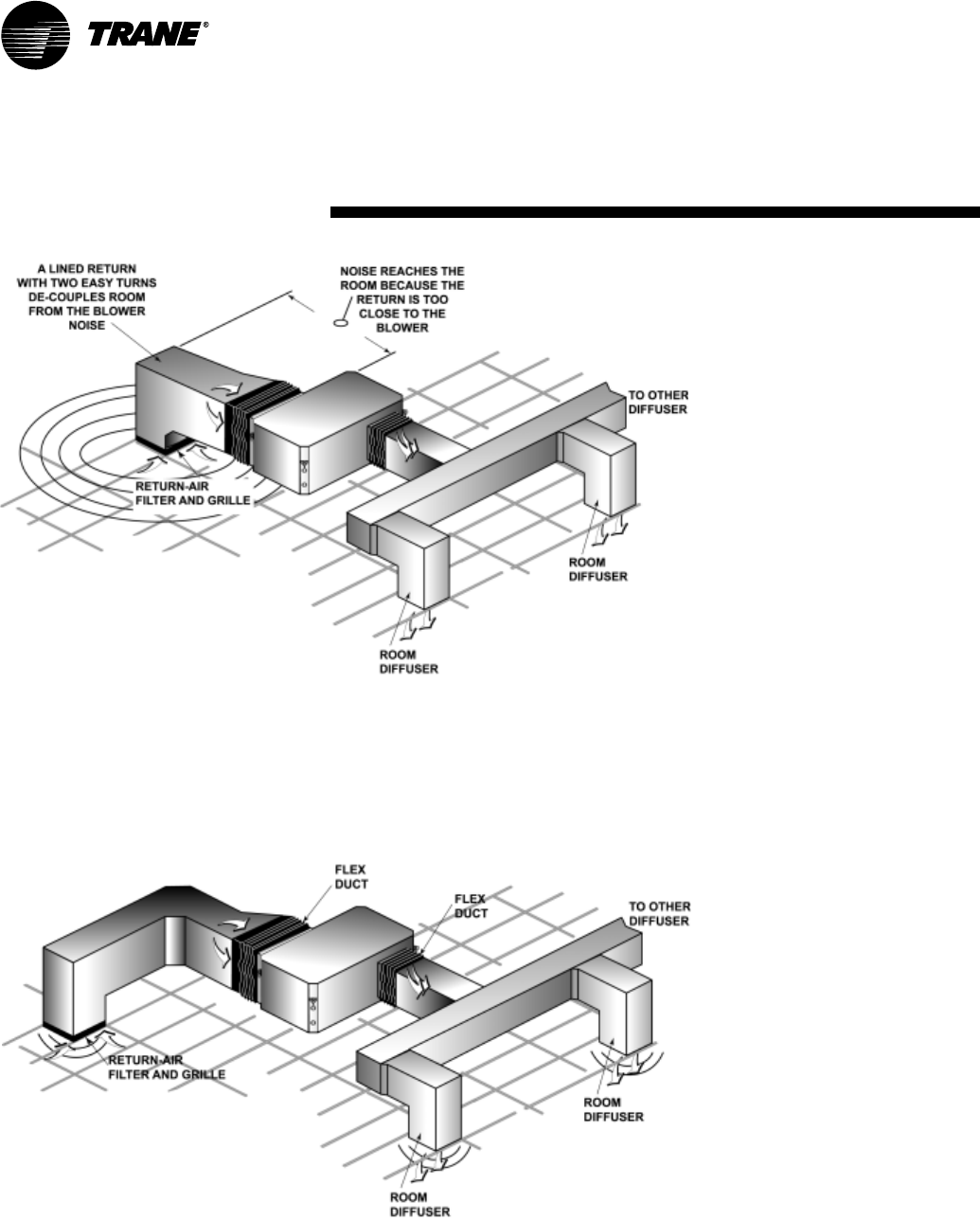
Sound control applies to the return
side of the duct design as well as the
supply side. Figure 36, demonstrates
a poor installation. Note that the
return air opening is close to the
cabinet of the unit.
Figure 37 graphic represents proper
installation of return-air duct. This
includes
• Two 90-degree bends prior to the
intake
• Lining the first 10 feet of the
return air duct
• Locating the return-air intake
away from the unit blower
A duct system with noise control
in-mind can be designed by:
• Keeping air flow velocities low
• Using aerodynamic fittings
• Using a duct liner if metal duct is
applied
• Avoiding line-of-sight connec-
tions between a noise source and
an outlet
• Avoiding line-of-sight connection
between a noise source and an
inlet
• By properly locating balancing
dampers
• Sealing cracks, seams and joints
in the duct run and equipment
panels
• Blocking transmission through
walls, ceiling and floors
• Mounting and supporting the
ductwork with isolation devices
that absorb vibration
• Using flexible duct connections
• Using flexible braided hoses on
the water connections
Application
Considerations
Figure 36: Improper return-air ducting
Figure 37: Proper return-air ducting
WSHP-PRC001-EN 29
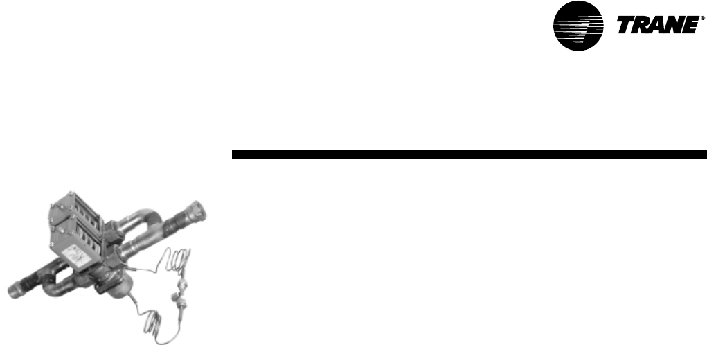
Using Water Regulating Valves
The function of the water regulating
valve assembly is to minimize the
amount of water which flows through
the water-source heat pump. These
valves are most often used in systems
where the water is wasted, but may
also be used in boiler/cooling tower in-
volving variable speed pumping. In a
variable speed application, the valves
are used to meter desirable water flow
through the unit when the unit is run-
ning, and to stop water flow when the
unit is not running (but may not in-
clude a 100% shut-off).
The water regulating valve assembly
consists of two valves piped in paral-
lel. When the water-source heat
pump’s compressor is de-energized,
both valves are closed, allowing no
water to flow through the unit. But,
when the unit compressor is ener-
gized, one of the valves is closed and
the other valve will allow water flow
through the unit.
In cooling mode, the valve controlling
the water flow is referred to as a direct
acting valve. As the spring tension in-
creases, the head pressure will also in-
crease. This is due to the decrease in
water flow through the unit. Note, the
valve is being controlled by the head
pressure. As the head pressure in-
creases, the water flow increases, and
vice versa. The valve is controlled by
two pressures. The refrigerant pres-
sure in the high side of the system,
and the spring pressure, acting on the
opposite side of the valve.
Note: The spring tension on the direct
acting valve may be adjusted to main-
tain a desired head pressure.
When the unit is OFF, or is in the heat-
ing mode, the valve closes. This is be-
cause the pressure acting on the valve
is out of the spring set-range.
In the heating mode, the valve control-
ling the water flow is referred to a a re-
verse acting valve. As the spring
tension increases, the suction pres-
sure will increase. This is due to the in-
crease in water flow through the unit.
Note, the valve is being controlled by
the suction pressure. As the suction
pressure decreases, the water flow in-
creases, and vice versa. The valve is
controlled by two pressures. The re-
frigerant pressure in the low side of
the system, and the spring pressure,
acting on the opposite side of the
valve.
Note: The spring tension on the re-
verse acting valve may be adjusted to
maintain a desired suction pressure.
When the unit is OFF, or is in the cool-
ing mode, the valve closes. This is be-
cause the pressure acting on the valve
is out of the spring set-range.
Both the direct acting and the reverse
acting valves should be tapped into
the same refrigerant line via a schraed-
er connection. This line must be a high
pressure line when the unit is in the
cooling mode, and a low pressure line
when the unit is in the heating mode.
The only line that will accommodate
this condition is the vapor line running
between the reversing valve and the
water-to-refrigerant heat exchanger.
Note: In many applications, a water
regulating valve may be used to meter
water flow to the equipment instead of
metering refrigerant flow to the equip-
ment. This is typically applied when
the equipment does not contain a ther-
mal expansion refrigerant metering
device. Trane places a thermal expan-
sion valve on all water-source and
ground-source heat pumps to provide
maximum performance of the equip-
ment. Capillary tube assemblies are
not used on Trane water-source or
ground-source heat pump equipment.
Therefore, a water regulating valve is
not required on most equipment appli-
cations.
Application
Considerations
30 WSHP-PRC001-EN
Types of Applications
In systems that use a boiler/cooling
tower design, water pumps are placed
between the auxiliary equipment
(boiler, cooling tower, etc.) and the
WSHPs to ensure positive water
pressure throughout the system.
Through this placement, the pump is
able to pressurize the piping that
serves the units, allowing the
regulated makeup water to pressurize
the pump section.
With this application, the cooling
tower is used to dissipate heat from
the condensing process. The
condensing water is cooled for
recirculation back to the
water-to-refrigerant heat exchanger by
using a combination of heat and mass
transfer by evaporation. The type of
cooling tower chosen for the
application may include an
open-circuit cooling tower with a
gasket-plate heat exchanger to close
the loop, or a closed-circuit fluid
cooler design.
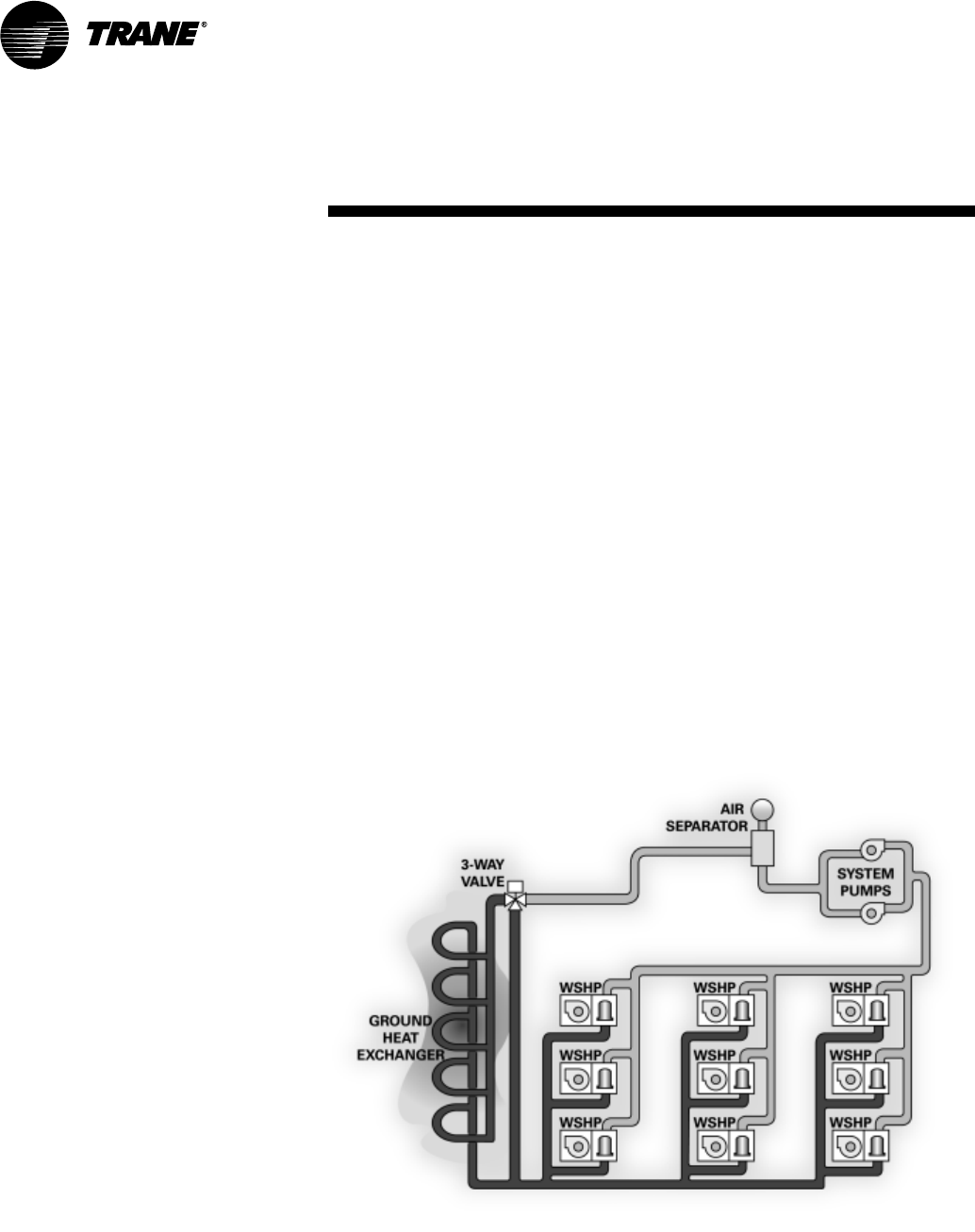
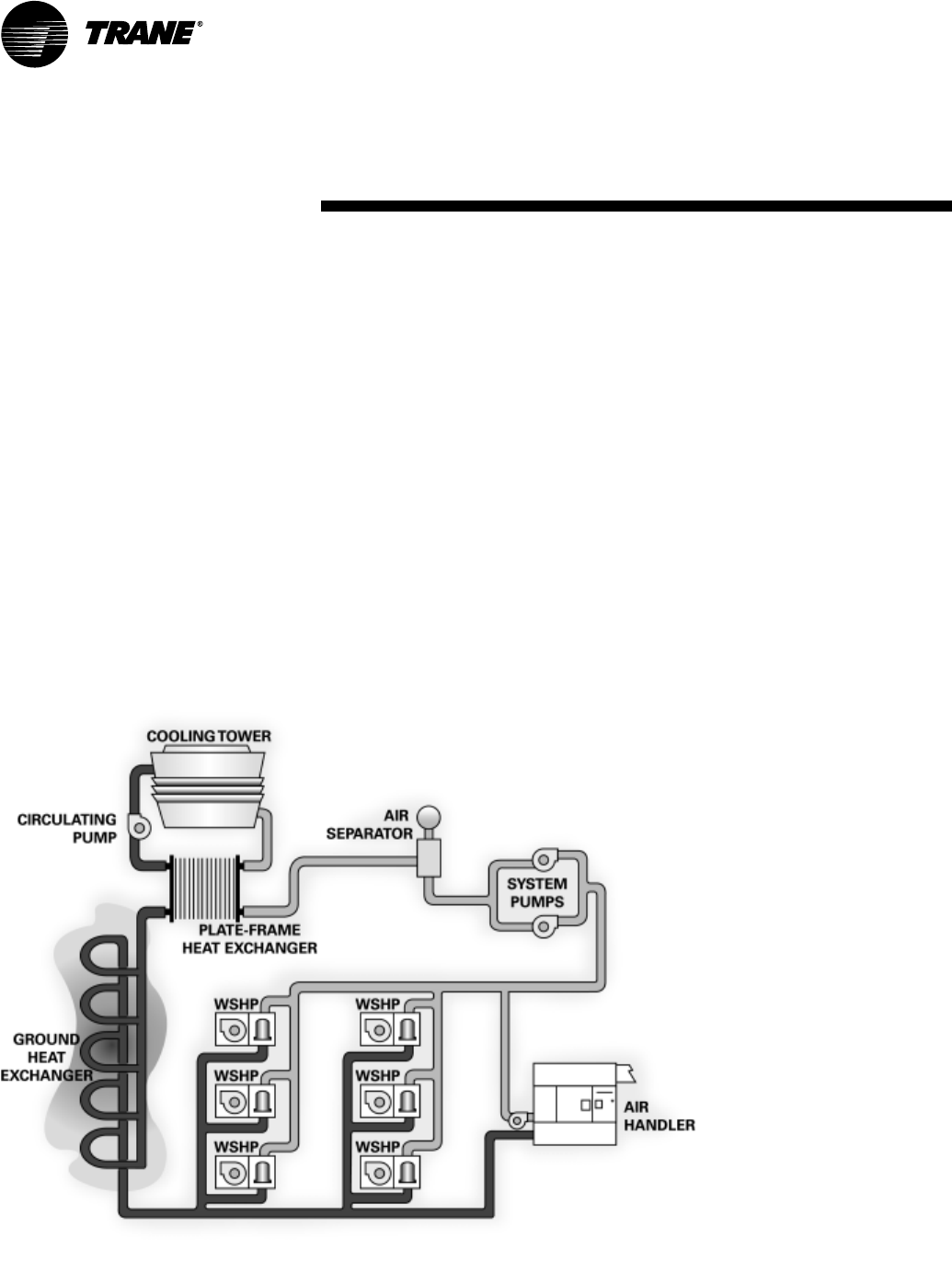
Hybrid Systems
Some systems have evolved into a hy-
brid (combination) system due to
building additions/phases or new re-
quirements.
A hybrid system may have began with
a geothermal ground loop heat ex-
changer used to extract or add heat to
the building. As additional rooms or
buildings were added onto the sys-
tem, the ground loop design became
undersized for the new demand. A
cooling tower may be the solution to
off-load the peak demand of the new
building addition. This may be an inex-
pensive means of tempering the loop
to it’s appropriate working conditions.
The cooling tower may be used in con-
junction with the loop to lower loop
temperatures during off-peak hours
(at night) to support the peak load of
the loop during the day.
Other additions may include a require-
ment for fresh-air ventilation. A
fresh-air, air handler, along with a
chiller may be introduced to the closed
loop system to allow tempered
fresh-air into the building.
The buildings heating and cooling
needs are not based off of one type of
component, but perform harmonious
of each other. Because the loop is
closed, heat recovery from the loop it-
self can be shared with the other major
components.
The heat pumps are capable of heat-
ing or cooling a space independent
of one another to provide individ-
ual heating and cooling needs.
A hybrid system should be con-
sidered on existing building design
when an offset of cooling energy is a
requirement. See Figure 38 for hybrid
system design.
Application
Considerations
Figure 38: Hybrid system design

WSHP-PRC001-EN 31
The performance standard ARI/ISO
13256-1 became effective Jan. 1, 2000.
It replaces ARI standards 320, 325 and
330. This new standard has three ma-
jor categories: Water Loop (ARI 320),
Ground Water (ARI 325), Ground Loop
(ARI 330). Although these standards
are similar there are some differences.
The cooling efficiency is measured in
EER but includes a Watt-per-Watt unit
of measure similar to the traditional
COP measurement.
The entering water temperature has
changed to reflect the centigrade tem-
perature scale. For instance the water
loop heating test is performed with
68-degree F (20-degree C) water in-
stead of 70-degree F. The cooling tests
are performed with 80.6-degree F
(27-degree C) dry bulb and 66.2-de-
gree F (19-degree C) wet bulb entering
air instead of the traditional 80-degree
F dry bulb, and 67-degree F wet bulb
entering air temperatures. This data
(80.6/66.2) may be converted to 80/67
by using the entering air correction ta-
ble.
A pump power correction has been
added onto the existing power con-
sumption. Within each model, only
one water flow rate is specified for
each performance category, and
pumping watts are calculated utilizing
the pump power correction formula:
(gpm x 0.0631) x press drop x 2990) /
300.
Note: gpm relates to water flow, and
press drop relates to the drop through
the unit heat exchanger at rated water
flow in feet of head.
The fan power is corrected to zero ex-
ternal static pressure. The nominal air-
flow is rated at a specific external
static pressure. This effectively reduc-
es the power consumption of the unit,
and increases cooling capacity but de-
creases heating capacity. These watts
are significant enough in most cases
to increase EER and COP over ARI 320,
325, and 330 ratings.
Cooling Dominated
Applications
If humidity levels are moderate to high
in a cooling dominated application,
the heat pump should be selected to
meet or exceed the calculated sensible
load. Also, the unit’s sensible capacity
should be no more than 115% of the
total cooling load (sensible + latent),
unless the calculated latent load is less
than the latent capacity of the unit.
The sensible-to-total cooling ratio can
be adjusted with airflow. If the airflow
is lowered, the unit latent capacity will
increase. When less air is pulled
across the DX coil, more moisture will
condense from the air.
Heating Dominated
Applications
Unit sizing in heating dominated appli-
cations is based upon humidity levels
for the climate, and goals for operating
cost and installation costs.
If humidity levels are moderate, the
heat pump should be selected with the
heating capacity equal to 125% of the
cooling load.
If humidity levels are low in the appli-
cation and low operating cost is im-
portant, the heat pump and ground
loop should be sized for 90% to 100%
of the heating load.
If humidity levels are low and lower
initial cost is important, then the heat
pump and ground loop should be
sized for 70% to 85% of the heating
load, with the remaining load to be
treated with electric resistance heat.
Installation cost will be reduced in this
approach because of the smaller heat
pump selection and less loop materi-
als.
In general, the system will not use
enough electric heat to offset the high-
er installation costs associated with a
fully sized or oversized system.
Finally, a unit sized for the entire heat-
ing load in a heating dominated appli-
cation will be oversized in cooling.
Comfort is reduced from increased
room humidity caused by short-run
times. Short cycling will also shorten
the life expectancy of the equipment
and increase power consumption and
operating cost.
Many rebate incentives require the
heat pump and ground loop to be
sized for the entire heating load. Check
with you local utility for their require-
ments.
Selection Program
All WSHP products should be selected
through the Trane Official Product Se-
lection System, TOPSS.
If this program has not been made
available, ask a local Trane sales engi-
neer to supply the desired selections
or provide a copy of the program.
Required Fields
The first step in the selection is to de-
termine either:
Total cooling capacity
Sensible capacity
Heating capacity
The maximum allowable water pres-
sure drop and selection ranges can
also be identified.
Selection
Procedure

32 WSHP-PRC001-EN
Model
Number
DIGITS 1-3: UNIT
CONFIGURATION
GEH = High Efficiency Horizontal
GEV = High Efficiency Vertical
DIGIT 4: DEVELOPMENT
SEQUENCE B
DIGITS 5-7: NOMINAL CAPACITY
006 = 1/2 Ton
009 = 3/4 Ton
012 = 1 Ton
015 = 1 1/4 Ton
018 = 1 1/2 Ton
024 = 2 Ton
030 = 2 1/2 Ton
036 = 3 Ton
040 = 3 1/3 Ton
(vertical ONLY)
042 = 3 1/2 Ton
DIGIT 8: VOLTAGE (Volts/Hz/Phase)
0 = 115/60/1 6 = 220-240/50/1
1 = 208/60/1 7 = 265/60/1
2 = 230/60/1 8 = 230/60/3
3 = 208/60/3 9 = 380-415/50/3
4 = 460/60/3
5 = 575/60/3
DIGITS 9: HEAT EXCHANGER
1 = Copper-Water Coil
2 = Cupro-Nickel Water Coil
DIGITS 10: CURRENT DESIGN
SEQUENCE
DIGITS 11: REFRIGERATION
CIRCUIT
0 = Heating and Cooling Circuit
2 = Heating and Cooling Circuit
with Hot Gas Reheat
3 = Heating and Cooling Circuit
with Waterside Economizer
4 = Heating and Cooling Circuit
with HGR and WSE
A = Cooling ONLY Circuit
C = Cooling ONLY Circuit
with Hot Gas Reheat
D = Cooling ONLY Circuit
with Waterside Economizer
E = Cooling ONLY Circuit
with HGR and WSE
DIGITS 12: BLOWER
CONFIGURATION
1 = Standard Blower Motor
2 = High Static Blower Motor
DIGIT 13: CUSTOMER CHANNEL
1 = Boiler/Tower Design for Trane
Commercial Group
2 = Geothermal Design for Trane
Commercial Group
5 = Trane International Group
DIGIT 14: OPEN DIGIT = 0
DIGIT 15: SUPPLY-AIR
ARRANGEMENT
B = Back Supply-Air Arrangement
F = Front Supply-Air Arrangement
L = Left Supply-Air Arrangement
R = Right Supply-Air Arrangement
T = Top Supply-Air Arrangement
DIGIT 16: RETURN-AIR
ARRANGEMENT
L = Left Return-Air Arrangement
R = Right Return-Air Arrangement
DIGIT 17: CONTROL TYPES
0 = Basic 24 V Controls
D = Deluxe 24 V Controls
C = Tracer ZN510 Controls
B = Tracer ZN524 Controls
DIGITS 18: TSTAT/SENSOR
LOCATION
0 = Wall Mounted Location
1 = Unit Mounted Location with
Standard Entry
2 = Unit Mounted Location with
Keylock Entry
DIGITS 19: FAULT SENSORS
0 = No Fault Sensor
1 = Condensate Overflow Sensor
2 = Filter Maintenance Timer
3 = Condensate Overflow and Filter
Maitenance Timer
4 = Fan Status Sensor
6 = Condensate Overflow and Fan
Status
H = Fan Status and Filter
Maintenance Timer
J = Fan Status, Filter Maintenance
Timer and Condensate Overflow
Sensor
DIGITS 20: TEMPERATURE
SENSOR
0 = No Additional Temperature
Sensor
1 = Entering Water Sensor
DIGITS 21: NIGHT SETBACK
CONTROL
0 = No Night Setback Relay
N = Night Setback Relay
DIGITS 22: ELECTRIC HEAT
0 = No Electric Heat
1 = Internal Boilerless Electric Heat
Horizontal/Vertical Water-Source Comfort System
510 15 20
G E H B 036 1 1 D 0 1 1 0 D L D 0 1 0 N 0 0 1 1 0 0 0 1 0 0 0 0 000
30
25
048 = 4 Ton
060 = 5 Ton

WSHP-PRC001-EN 33
DIGITS 23: UNIT MOUNTED
DISCONNECT
0 = No Unit Mounted Disconnect
DIGITS 24: FILTER TYPE
0 = 1" Filter; No Duct Flange
1 = 1" Throwaway Filter
2 = 2" Throwaway Filter
DIGITS 25: ACOUSTIC
ARRANGEMENT
0 = Enhanced Sound Attenuation
1 = Deluxe Sound Attenuation
DIGITS 26: FACTORY
CONFIGURATION
0 = Standard Factory Configuration
DIGITS 27: PAINT COLOR
0 = No Paint Selection Available
DIGITS 28: OUTSIDE AIR
0 = No Outside Air Option Available
DIGITS 29: PIPING
ARRANGEMENT
0 = Standard Piping Arrangement
1 = Standard Piping with Schrader
Connection for Water Regulating
Valve
DIGITS 30-36: DOES NOT APPLY
TO GEH or GEV
0000000 = Digits 30-36 are not
applicable to the GEH or
GEV products
Model
Number
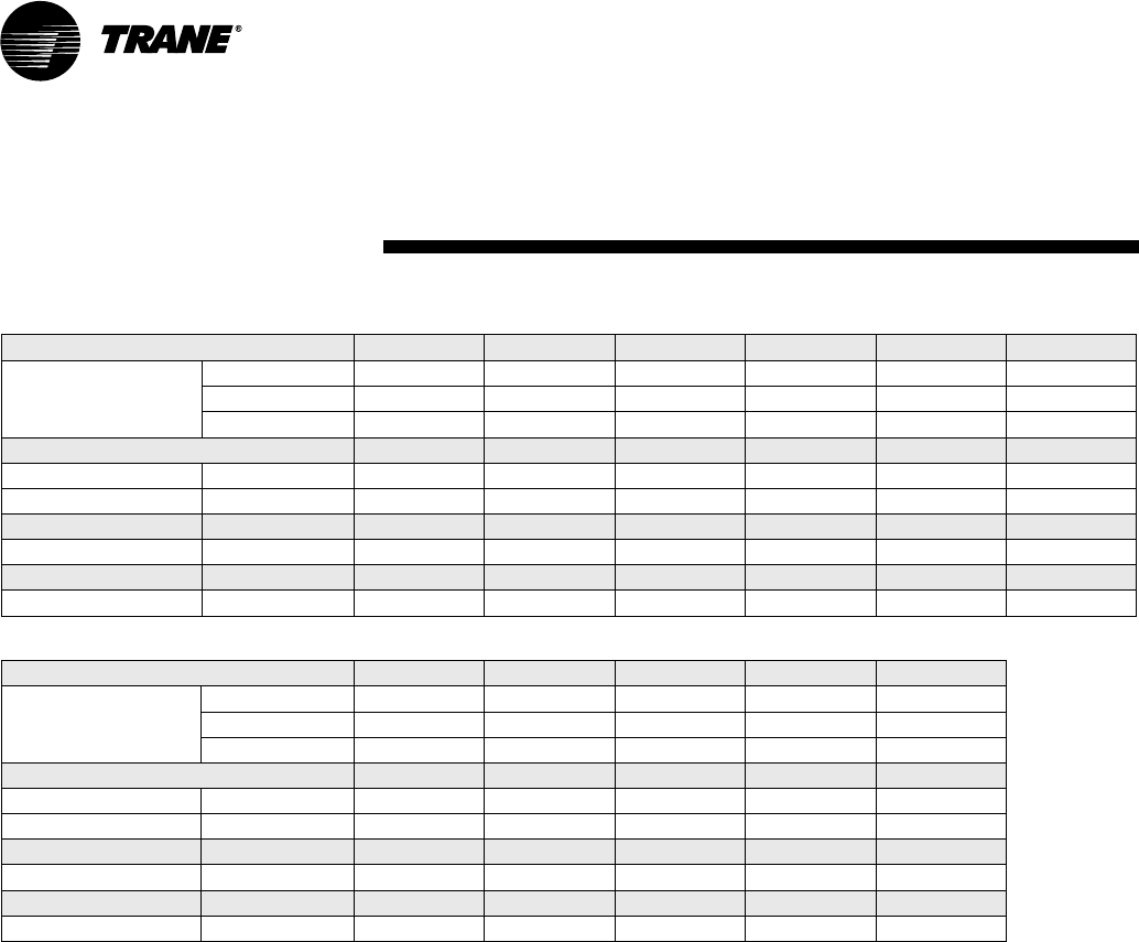
34 WSHP-PRC001-EN
Table G1: General data about the units
Table G2: General data about the units (continued)
Model GEH 006 009 012 015 018 024
Unit Size Length (in) 40 40 40 40 46 46
Height (in) 15 15 15 15 17 17
Width (in) 20 20 20 20 23 23
Compressor Type Rotary Rotary Rotary Rotary Rotary Reciprocating
Approximate Weight with Pallet (lb) 188 188 188 188 278 278
Approximate Weight without Pallet (lb) 158 158 158 158 248 248
Filter Size Actual (in) 14 5/8 x 20 1/4 14 5/8 x 20 1/4 14 5/8 x 20 1/4 14 5/8 x 20 1/4 16 3/8 x 23 5/8 16 3/8 x 23 5/8
Water in/out size (FPT) inches 1/2 1/2 1/2 1/2 3/4 3/4
Condensate size (NPTI) inches 3/4 3/4 3/4 3/4 3/4 3/4
Blower Wheel Size Direct Drive (in) 9 x 4 9 x 4 9 x 4 9 x 4 9 x 6 10 x 6
Model GEH 030 036 042 048 060
Unit Size Length (in) 46 50 50 58 58
Height (in) 17 19 19 21 21
Width (in) 23 25 25 33 33
Compressor Type Reciprocating Reciprocating Reciprocating Reciprocating Scroll
Approximate Weight with Pallet (lb) 278 318 318 428 428
Approximate Weight without Pallet (lb) 248 288 288 398 398
Filter Size Actual (in) 16 3/8 x 23 5/8 18 5/8 x 25 3/8 18 5/8 x 25 3/8 20 5/8 x 29 3/4 20 5/8 x 29 3/4
Water in/out size (FPT) inches 3/4 3/4 1 1 1
Condensate size (NPTI) inches 3/4 3/4 3/4 3/4 3/4
Blower Wheel Size Direct Drive (in) 10 x 6 12 x 8 12 x 8 12 x 11 12 x 11
General
Data
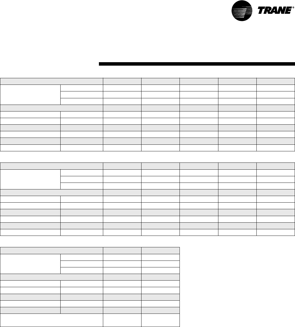
WSHP-PRC001-EN 35
Table G4: General data about the units
Table G5: General data about the units (continued)
Table G6: General data about the units (continued)
Model GEV 006 009 012 015 018
Unit Size Length (in) 21 1/2 21 1/2 21 1/2 21 1/2 21 1/2
Height (in) 31 1/4 31 1/4 31 1/4 31 1/4 39 1/4
Width (in) 19 1/2 19 1/2 19 1/2 19 1/2 21 1/2
Compressor Type Rotary Rotary Rotary Rotary Reciprocating
Approximate Weight with Pallet (lb) 178 178 178 178 268
Approximate Weight without Pallet (lb) 158 158 158 158 248
Filter Size Actual (in) 15 7/8 x 19 7/8 15 7/8 x 19 7/8 15 7/8 x 19 7/8 15 7/8 x 19 7/8 17 7/8 x 24 7/8
Water in/out size (FPT) inches 1/2 1/2 1/2 1/2 3/4
Condensate size (NPTI) inches 3/4 3/4 3/4 3/4 3/4
Blower Wheel Size Direct Drive (in) 9 x 4 9 x 4 9 x 4 9 x 4 9 x 6
Model GEV 024 030 036 040 042
Unit Size Length (in) 21 1/2 21 1/2 26 1/2 21 1/2 26 1/2
Height (in) 39 1/4 39 1/4 41 7/8 39 1/4 41 7/8
Width (in) 21 1/2 21 1/2 24 1/2 21 1/2 24 1/2
Compressor Type Reciprocating Reciprocating Reciprocating Reciprocating Reciprocating
Approximate Weight with Pallet (lb) 268 268 308 268 308
Approximate Weight without Pallet (lb) 248 248 288 248 288
Filter Size Actual (in) 17 7/8 x 24 7/8 17 7/8 x 24 7/8 19 7/8 x 24 7/8 17 7/8 x 24 7/8 19 7/8 x 24 7/8
Water in/out size (FPT) inches 3/4 3/4 3/4 3/4 3/4
Condensate size (NPTI) inches 3/4 3/4 3/4 3/4 3/4
Blower Wheel Size Direct Drive (in) 10 x 6 10 x 6 10 x 6 10 x 6 12 x 8
Model GEV 048 060
Unit Size Length (in) 30 1/2 30 1/2
Height (in) 46 7/8 46 7/8
Width (in) 26 1/2 26 1/2
Compressor Type Reciprocating Scroll
Approximate Weight with Pallet (lb) 396 396
Approximate Weight without Pallet (lb) 348 348
Filter Size Actual (in) 27 7/8 x 29 7/8 27 7/8 x 29 7/8
Water in/out size inches 1 FPT 1 FPT
Condensate size (NPTI) inches 3/4 3/4
Blower Wheel Size and quantity 10 x 10 (DD)-Std
12 x 11 (DD)-Hi
12 x 11 (DD)
General
Data
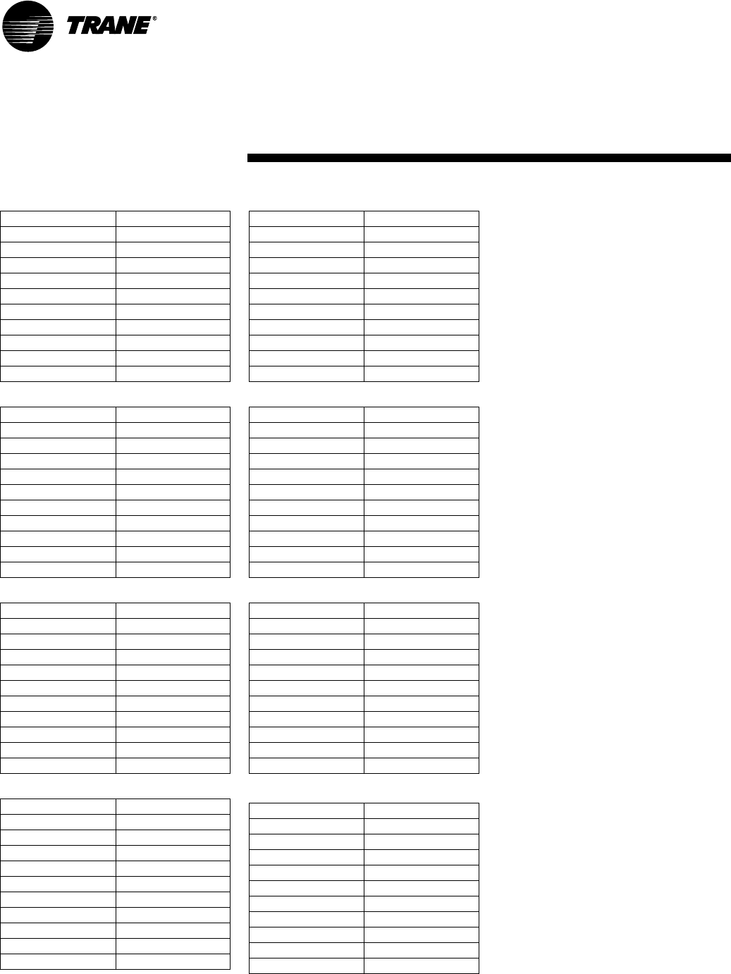
36 WSHP-PRC001-EN
Table G8: GEH/GEV 006, 009
Table G9: GEH/GEV 012
Table G10: GEH/GEV 015
Table G11: GEH 018, 024, 030
Working Pressure 425
Tubes High 14
Tubes Deep 2
No. of Circuits 1
Finned vol. (h,w,d) 14 x 16 x 1.734
Coil Surface Area (Ft2)1.56
Fins Per Inch 12
Tube Material Copper
Tube O D (i n ) 3/8
Wall Thickness 0.014
Return Bends Copper
Working Pressure 425
Tubes High 14
Tubes Deep 3
No. of Circuits 2
Finned vol. (h,w,d) 14 x 16 x 2.598
Coil Surface Area (Ft2)1.56
Fins Per Inch 12
Tube Material Copper
Tube O D (i n ) 3/8
Wall Thickness 0.014
Return Bends Copper
Working Pressure 425
Tubes High 14
Tubes Deep 3
No. of Circuits 1
Finned vol. (h,w,d) 14 x 16 x 2.598
Coil Surface Area (Ft2)1.56
Fins Per Inch 12
Tube Material Copper
Tube O D (i n ) 3/8
Wall Thickness 0.014
Return Bends Copper
Working Pressure 425
Tubes High 16
Tubes Deep 4
No. of Circuits 4
Finned vol. (h,w,d) 16 x 19 x 3.464
Coil Surface Area (Ft2)2.11
Fins Per Inch 12
Tube Material Copper
Tube O D (i n ) 3/8
Wall Thickness 0.014
Return Bends Copper
Table G12: GEV 018, 024, 030, 040
Table G13: GEH/GEV 036, 042
Table G14: GEH 048, 060
Table G15: GEV 048, 060
Working Pressure 425
Tubes High 21
Tubes Deep 4
No. of Circuits 4
Finned vol. (h,w,d) 21 x 16 x 3.464
Coil Surface Area (Ft2)2.33
Fins Per Inch 12
Tube Material Copper
Tube OD (in) 3/8
Wall Thickness 0.014
Return Bends Copper
Working Pressure 425
Tubes High 18
Tubes Deep 4
No. of Circuits 6
Finned vol. (h,w,d) 18 x 21 x 3.464
Coil Surface Area (Ft2)2.63
Fins Per Inch 12
Tube Material Copper
Tube OD (in) 3/8
Wall Thickness 0.014
Return Bends Copper
Working Pressure 425
Tubes High 20
Tubes Deep 4
No. of Circuits 8
Finned vol. (h,w,d) 20 x 29 x 3.464
Coil Surface Area (Ft2)4.03
Fins Per Inch 12
Tube Material Copper
Tube OD (in) 3/8
Wall Thickness 0.014
Return Bends Copper
Working Pressure 425
Tubes High 24
Tubes Deep 4
No. of Circuits 8
Finned vol. (h,w,d) 24 x 25 x 3.464
Coil Surface Area (Ft2)4.17
Fins Per Inch 12
Tube Material Copper
Tube OD (in) 3/8
Wall Thickness 0.014
Return Bends Copper
General Data
Air-to-Refrigerant Coils
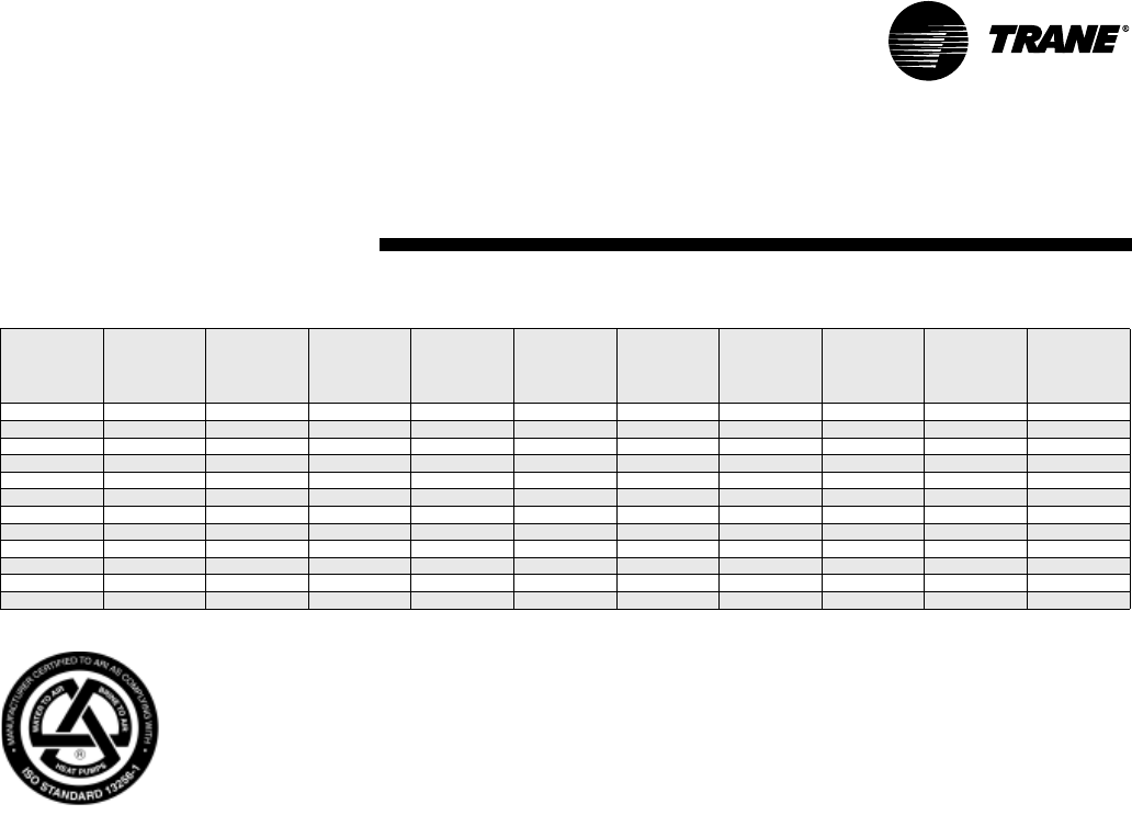
WSHP-PRC001-EN 37
Performance Data
ARI-ISO (WLHP/GLHP)
Table P1: ARI-ISO WLHP and GLHP Performance
Rated in accordance with ISO Standard 13256-1: 1998 (Water Loop Heat Pumps and Ground Loop
Heat Pumps).
Certified conditions are 86°F EWT, 80.6°F DB/66.2°F WB EAT in cooling and 68°F EWT, 68°F DB/59°F
WB EAT in heating. Data shown is for application performance only, as these conditions are typical
for WSHP systems.
Models with capacities greater than 135,000 BTUH are not included in the ARI water-to-air and
brine-to-air heat pump certification program.
Unit Size Rated Water
Flow
(GPM)
Rated Air
Flow
(SCFM)
Cooling
Capacity
WLHP
(BTUH)
EER
WLHP
Heating
Capacity
WLHP
(BTUH)
COP
WLHP
Cooling
Capacity
GLHP
(BTUH)
EER
GLHP
Heating
Capacity
GLHP
(BTUH)
COP
GLHP
006 1.5 190 7060 13.0 8160 4.3 6980 14.4 4690 3.1
009 2.1 285 8760 12.85 10900 4.6 8710 14.5 6100 3.1
012 2.8 380 12500 13.15 13200 4.35 12400 14.2 8700 3.2
015 3.5 460 14100 14.0 17200 4.8 14200 16.0 10200 3.45
018 4.2 570 19100 13.5 21600 4.45 18900 14.9 13000 3.15
024 5.5 760 25800 12.6 30400 4.35 26000 13.8 17800 3.25
030 6.9 900 28500 12.5 33100 4.25 28700 13.5 19800 3.1
036 8.3 1140 36000 13.7 41800 4.7 35200 14.5 22200 3.25
GEV 040 9.2 1200 38500 12.75 44200 4.2 38500 13.6 26100 3.1
042 9.7 1330 40200 12.05 47500 4.2 41700 13.4 27400 3.1
048 11.0 1520 49000 12.75 55300 4.25 49000 13.65 32000 3.1
060 14.5 1900 59300 12.8 72300 4.4 58500 13.75 43300 3.1

38 WSHP-PRC001-EN
Performance Data
006-Cooling
Table P2: GEH/GEV 006 Cooling Performance
Cooling performance data is tabulated at 80.6 F DB/66.2 F WB entering air at ARI/ISO 13256-1 rated CFM. For ARI/ISO 13256-1 certified ratings, see Table P1.
See Performance correction tables to correct performance at conditions other than those tabulated. Data shown is for unit performance only. Interpolation is
permissible. Extrapolation is not.
Rated GPM: 1.5 Maximum CFM: 152
Rated CFM: 190 Maximum CFM: 228
EWT GPM Tota l
Mbtuh
Sen
Mbtuh
SHR Power
kW
EER Reject
Mbtuh
LWT Feet
Head
45 1.0 8.4 5.5 0.66 0.46 18.3 10.0 65.0 1.5
45 1.2 8.4 5.6 0.66 0.45 18.8 10.0 61.6 2.1
45 1.4 8.5 5.6 0.66 0.45 18.8 10.0 59.3 2.7
45 1.5 8.5 5.6 0.66 0.44 19.3 10.0 58.3 3.0
45 1.6 8.5 5.6 0.66 0.44 19.3 10.0 57.5 3.4
45 1.7 8.5 5.6 0.66 0.43 19.7 10.0 56.7 3.7
45 1.8 8.5 5.6 0.66 0.43 19.8 10.0 56.1 4.1
55 1.0 8.0 5.4 0.68 0.46 17.3 9.5 74.1 1.4
55 1.2 8.0 5.4 0.68 0.45 17.8 9.5 70.9 2.0
55 1.4 8.0 5.5 0.68 0.45 17.9 9.6 68.7 2.6
55 1.5 8.1 5.5 0.68 0.44 18.3 9.6 67.8 2.9
55 1.6 8.1 5.5 0.68 0.44 18.4 9.6 67.0 3.2
55 1.7 8.1 5.5 0.68 0.44 18.4 9.6 66.3 3.5
55 1.8 8.1 5.6 0.69 0.43 18.8 9.6 65.6 3.9
68 1.0 7.4 5.3 0.71 0.50 14.9 9.2 86.3 1.4
68 1.2 7.5 5.3 0.71 0.49 15.3 9.2 83.3 1.9
68 1.4 7.6 5.4 0.71 0.48 15.7 9.2 81.1 2.4
68 1.5 7.6 6.0 0.80 0.48 15.8 9.2 80.3 2.7
68 1.6 7.6 5.4 0.71 0.47 16.2 9.2 79.5 3.0
68 1.7 7.6 5.4 0.71 0.47 16.2 9.2 78.9 3.3
68 1.8 7.7 5.5 0.71 0.47 16.3 9.3 78.3 3.6
77 1.0 7.1 5.2 0.73 0.55 12.9 9.0 95.0 1.3
77 1.2 7.2 5.2 0.73 0.54 13.3 9.0 92.1 1.8
77 1.4 7.3 5.3 0.73 0.53 13.7 9.1 90.0 2.3
77 1.5 7.3 5.3 0.73 0.53 13.7 9.1 89.2 2.6
77 1.6 7.3 5.3 0.73 0.52 14.1 9.1 88.4 2.9
77 1.7 7.3 5.4 0.73 0.52 14.1 9.1 87.8 3.1
77 1.8 7.4 5.4 0.73 0.52 14.2 9.1 87.2 3.4
86 1.0 6.8 5.1 0.74 0.61 11.2 8.9 103.9 1.3
86 1.2 6.9 5.2 0.75 0.60 11.5 8.9 101.0 1.7
86 1.4 7.0 5.2 0.75 0.59 11.8 9.0 98.9 2.2
86 1.5 7.0 5.3 0.75 0.59 11.9 9.0 98.1 2.5
86 1.6 7.0 5.3 0.75 0.59 11.9 9.1 97.4 2.7
86 1.7 7.1 5.3 0.75 0.58 12.2 9.1 96.7 3.0
86 1.8 7.1 5.3 0.75 0.58 12.2 9.1 96.1 3.3
95 1.0 6.5 5.0 0.76 0.67 9.8 8.8 112.8 1.2
95 1.2 6.6 5.1 0.77 0.67 9.9 8.9 109.9 1.6
95 1.4 6.7 5.2 0.77 0.66 10.2 9.0 107.9 2.1
95 1.5 6.7 5.2 0.77 0.65 10.4 9.0 107.0 2.4
95 1.6 6.8 5.2 0.77 0.65 10.4 9.0 106.3 2.6
95 1.7 6.8 5.3 0.77 0.65 10.5 9.0 105.7 2.9
95 1.8 6.9 5.3 0.77 0.64 10.7 9.0 105.1 3.2
105 1.0 6.2 4.9 0.79 0.74 8.4 8.8 122.7 1.2
105 1.2 6.3 5.0 0.79 0.74 8.6 8.9 119.9 1.6
105 1.4 6.4 5.1 0.79 0.73 8.8 8.9 117.8 2.0
105 1.5 6.5 5.1 0.79 0.72 9.0 8.9 117.0 2.2
105 1.6 6.5 5.2 0.79 0.72 9.1 9.0 116.3 2.5
105 1.7 6.6 5.2 0.79 0.72 9.1 9.0 115.7 2.8
105 1.8 6.6 5.2 0.79 0.71 9.3 9.0 115.1 3.0
115 1.0 6.0 4.9 0.81 0.84 7.1 8.8 132.9 1.1
115 1.2 6.1 5.0 0.82 0.83 7.3 8.9 130.0 1.5
115 1.4 6.2 5.1 0.82 0.82 7.5 9.0 128.0 1.9
115 1.5 6.2 5.1 0.82 0.82 7.6 9.0 127.2 2.2
115 1.6 6.3 5.1 0.82 0.81 7.7 9.0 126.4 2.4
115 1.7 6.3 5.2 0.82 0.81 7.8 9.1 125.8 2.7
115 1.8 6.4 5.2 0.82 0.81 7.9 9.1 125.2 3.0
120 1.0 5.8 4.8 0.82 0.91 6.4 9.0 138.1 1.0
120 1.2 6.0 4.9 0.83 0.90 6.6 9.0 135.2 1.4
120 1.4 6.1 5.0 0.83 0.90 6.7 9.1 133.2 1.9
120 1.5 6.1 5.1 0.83 0.89 6.9 9.1 132.3 2.1
120 1.6 6.2 5.1 0.83 0.89 6.9 9.2 131.6 2.4
120 1.7 6.2 5.2 0.83 0.88 7.0 9.2 131.0 2.6
120 1.8 6.2 5.2 0.83 0.88 7.1 9.3 130.4 2.9

WSHP-PRC001-EN 39
Performance Data
006-Heating
Table P3: GEH/GEV 006 Heating Performance
Heating performance data is tabulated at 68 F DB entering air at ARI/ISO 13256-1 rated CFM. For ARI/ISO 13256-1 certified ratings, see Table P1. See Perfor-
mance correction tables to correct performance at conditions other than those tabulated. Data shown is for unit performance only. Interpolation is permissible.
Extrapolation is not.
Rated GPM: 1.5 Maximum CFM: 152
Rated CFM: 190 Maximum CFM: 228
EWT GPM Htg Cap
Mbtuh
Absorb
Mbtuh
Power
kW
COP LWT Feet
Head
25 1.0 5.0 3.2 0.52 2.8 18.5 1.5
25 1.2 5.2 3.4 0.52 2.9 19.4 2.2
25 1.4 5.2 3.4 0.53 2.9 20.2 3.0
25 1.5 5.2 3.4 0.53 2.9 20.5 3.4
25 1.6 5.2 3.3 0.53 2.8 20.8 3.8
25 1.7 5.2 3.4 0.53 2.9 21.1 4.2
25 1.8 5.2 3.4 0.53 2.9 21.2 4.6
32 1.0 5.5 3.6 0.54 3.0 24.7 1.5
32 1.2 5.7 3.8 0.54 3.1 25.6 2.1
32 1.4 5.7 3.9 0.54 3.1 26.5 2.9
32 1.5 5.7 3.8 0.55 3.0 26.9 3.2
32 1.6 5.7 3.8 0.55 3.0 27.2 3.6
32 1.7 5.7 3.8 0.55 3.0 27.5 4.0
32 1.8 5.8 3.9 0.55 3.1 27.7 4.5
45 1.0 6.5 4.6 0.57 3.3 35.9 1.5
45 1.2 6.7 4.8 0.57 3.5 37.0 2.1
45 1.4 6.8 4.9 0.57 3.5 38.0 2.7
45 1.5 6.8 4.9 0.57 3.5 38.5 3.0
45 1.6 6.8 4.9 0.58 3.5 38.9 3.4
45 1.7 6.9 4.9 0.58 3.5 39.2 3.7
45 1.8 6.9 5.0 0.58 3.5 39.5 4.1
55 1.0 7.4 5.4 0.59 3.7 44.3 1.4
55 1.2 7.6 5.6 0.60 3.7 45.7 2.0
55 1.4 7.7 5.7 0.60 3.8 46.9 2.6
55 1.5 7.8 5.7 0.60 3.8 47.4 2.9
55 1.6 7.8 5.7 0.60 3.8 47.8 3.2
55 1.7 7.8 5.8 0.60 3.8 48.2 3.5
55 1.8 7.9 5.8 0.60 3.8 48.5 3.9
68 1.0 8.5 6.4 0.62 4.0 55.2 1.4
68 1.2 8.8 6.6 0.63 4.1 56.9 1.9
68 1.4 8.9 6.7 0.63 4.1 58.4 2.4
68 1.5 8.9 6.8 0.63 4.1 59.0 2.7
68 1.6 8.9 6.8 0.63 4.2 59.5 3.0
68 1.7 9.0 6.8 0.63 4.2 60.0 3.3
68 1.8 9.0 6.9 0.63 4.2 60.4 3.6
75 1.0 9.1 6.9 0.64 4.1 61.2 1.4
75 1.2 9.3 7.2 0.64 4.3 63.0 1.8
75 1.4 9.4 7.3 0.64 4.3 64.6 2.3
75 1.5 9.5 7.3 0.64 4.3 65.3 2.6
75 1.6 9.5 7.3 0.65 4.3 65.9 2.9
75 1.7 9.5 7.3 0.65 4.3 66.4 3.2
75 1.8 9.6 7.3 0.65 4.3 66.8 3.5
86 1.0 9.8 7.5 0.66 4.3 70.9 1.3
86 1.2 10.1 7.8 0.66 4.5 72.9 1.7
86 1.4 10.2 7.9 0.67 4.4 74.7 2.2
86 1.5 10.2 7.9 0.67 4.5 75.4 2.5
86 1.6 10.2 7.9 0.67 4.5 76.1 2.7
86 1.7 10.2 7.9 0.67 4.5 76.6 3.0
86 1.8 10.2 8.0 0.67 4.5 77.1 3.3
Table P4: 006 Fan Correction Factors
Entering
CFM
Cooling
Capacity
Sensible
Capacity
Cooling
Input
Watts
Heating
Capacity
Heating
Input
Watts
152 0.974 0.892 0.965 0.972 1.032
162 0.981 0.920 0.973 0.979 1.023
171 0.987 0.945 0.981 0.986 1.016
181 0.994 0.973 0.991 0.993 1.008
190 1.000 1.000 1.000 1.000 1.000
209 1.012 1.051 1.020 1.013 0.984
218 1.018 1.077 1.030 1.020 0.977
228 1.025 1.105 1.042 1.027 0.968

40 WSHP-PRC001-EN
Performance Data
009-Cooling
Table P5: GEH/GEV 009 Cooling Performance
Cooling performance data is tabulated at 80.6 F DB/66.2 F WB entering air at ARI/ISO 13256-1 rated CFM. For ARI/ISO 13256-1 certified ratings, see Table P1.
See Performance correction tables to correct performance at conditions other than those tabulated. Data shown is for unit performance only. Interpolation is
permissible. Extrapolation is not.
Rated GPM: 2.1 Maximum CFM: 228
Rated CFM: 285 Maximum CFM: 342
EWT GPM Tota l
Mbtuh
Sen
Mbtuh
SHR Power
kW
EER Reject
Mbtuh
LWT Feet
Head
45 1.4 10.6 7.4 0.70 0.56 18.9 12.5 62.9 2.7
45 1.7 10.6 7.4 0.70 0.54 19.6 12.4 59.6 3.8
45 1.9 10.7 7.3 0.68 0.53 20.2 12.5 58.2 4.5
45 2.1 10.7 7.3 0.68 0.52 20.6 12.5 56.9 5.4
45 2.2 10.7 7.3 0.68 0.52 20.6 12.5 56.3 5.8
45 2.3 10.7 7.3 0.68 0.52 20.6 12.5 55.8 6.2
45 2.5 10.7 7.3 0.68 0.52 20.6 12.5 55.0 7.1
55 1.4 10.1 7.1 0.70 0.56 18.0 12.0 72.2 2.6
55 1.7 10.2 7.1 0.70 0.54 18.9 12.0 69.2 3.6
55 1.9 10.2 7.1 0.70 0.53 19.2 12.0 67.6 4.3
55 2.1 10.2 7.1 0.70 0.52 19.6 12.0 66.4 5.0
55 2.2 10.2 7.1 0.70 0.52 19.6 12.0 65.9 5.4
55 2.3 10.2 7.1 0.70 0.52 19.6 12.0 65.4 5.9
55 2.5 10.2 7.1 0.70 0.52 19.6 12.0 64.6 6.7
68 1.4 9.4 6.8 0.72 0.62 15.2 11.5 84.5 2.4
68 1.7 9.5 6.9 0.73 0.60 15.8 11.6 81.6 3.3
68 1.9 9.5 6.9 0.73 0.59 16.1 11.5 80.1 4.0
68 2.1 9.5 6.9 0.73 0.58 16.4 11.5 78.9 4.7
68 2.2 9.5 6.9 0.73 0.57 16.7 11.5 78.4 5.0
68 2.3 9.5 6.9 0.73 0.57 16.7 11.5 78.0 5.4
68 2.5 9.5 6.9 0.73 0.57 16.7 11.5 77.2 6.2
77 1.4 8.9 6.6 0.74 0.68 13.1 11.2 93.1 2.3
77 1.7 9.0 6.7 0.74 0.66 13.6 11.3 90.3 3.1
77 1.9 9.0 6.7 0.74 0.65 13.8 11.2 88.8 3.7
77 2.1 9.0 6.7 0.74 0.64 14.1 11.2 87.7 4.4
77 2.2 9.0 6.7 0.74 0.64 14.1 11.2 87.2 4.8
77 2.3 9.1 6.7 0.74 0.63 14.4 11.3 86.8 5.2
77 2.5 9.0 6.7 0.74 0.63 14.3 11.2 85.9 5.9
86 1.4 8.5 6.4 0.75 0.76 11.2 11.1 101.9 2.2
86 1.7 8.5 6.5 0.76 0.74 11.5 11.0 99.0 3.0
86 1.9 8.5 6.5 0.76 0.73 11.6 11.0 97.6 3.6
86 2.1 8.6 6.5 0.76 0.72 11.9 11.1 96.6 4.2
86 2.2 8.6 6.5 0.76 0.71 12.1 11.0 96.1 4.6
86 2.3 8.6 6.5 0.76 0.71 12.1 11.0 95.6 4.9
86 2.5 8.6 6.5 0.76 0.71 12.1 11.0 94.9 5.7
95 1.4 8.0 6.2 0.78 0.84 9.5 10.9 110.6 2.0
95 1.7 8.1 6.3 0.78 0.82 9.9 10.9 107.9 2.8
95 1.9 8.1 6.3 0.78 0.81 10.0 10.9 106.5 3.4
95 2.1 8.1 6.3 0.78 0.80 10.1 10.8 105.4 4.1
95 2.2 8.1 6.3 0.78 0.80 10.1 10.8 104.9 4.4
95 2.3 8.1 6.3 0.78 0.79 10.3 10.8 104.4 4.7
95 2.5 8.1 6.3 0.78 0.79 10.3 10.8 103.7 5.5
105 1.4 7.5 6.0 0.80 0.93 8.1 10.7 120.4 2.0
105 1.7 7.5 6.0 0.80 0.92 8.2 10.6 117.6 2.7
105 1.9 7.6 6.0 0.79 0.90 8.4 10.7 116.3 3.3
105 2.1 7.6 6.0 0.79 0.89 8.5 10.6 115.2 3.9
105 2.2 7.6 6.0 0.79 0.89 8.5 10.6 114.7 4.2
105 2.3 7.6 6.0 0.79 0.88 8.6 10.6 114.3 4.6
105 2.5 7.6 6.0 0.79 0.88 8.6 10.6 113.5 5.3
115 1.4 6.8 5.7 0.84 1.01 6.7 10.3 129.8 1.9
115 1.7 6.8 5.7 0.84 1.00 6.8 10.2 127.1 2.7
115 1.9 6.9 5.7 0.83 0.98 7.0 10.2 125.9 3.2
115 2.1 6.9 5.7 0.83 0.97 7.1 10.2 124.8 3.8
115 2.2 6.9 5.7 0.83 0.97 7.1 10.2 124.4 4.2
115 2.3 6.9 5.7 0.83 0.97 7.1 10.2 124.0 4.5
115 2.5 6.9 5.7 0.83 0.96 7.2 10.2 123.2 5.2
120 1.4 6.2 5.6 0.90 1.04 6.0 9.8 134.1 1.9
120 1.7 6.3 5.5 0.87 1.03 6.1 9.8 131.7 2.6
120 1.9 6.3 5.5 0.87 1.02 6.2 9.8 130.4 3.2
120 2.1 6.4 5.5 0.86 1.01 6.3 9.9 129.5 3.8
120 2.2 6.4 5.5 0.86 1.00 6.4 9.8 129.0 4.2
120 2.3 6.4 5.5 0.86 1.00 6.4 9.8 128.6 4.5
120 2.5 6.4 5.5 0.86 1.00 6.4 9.8 127.9 5.2

WSHP-PRC001-EN 41
Performance Data
009-Heating
Table P6: GEH/GEV 009 Heating Performance
Heating performance data is tabulated at 68 F DB entering air at ARI/ISO 13256-1 rated CFM. For ARI/ISO 13256-1 certified ratings, see Table P1. See Perfor-
mance correction tables to correct performance at conditions other than those tabulated. Data shown is for unit performance only. Interpolation is permissible.
Extrapolation is not.
Rated GPM: 2.1 Maximum CFM: 228
Rated CFM: 285 Maximum CFM: 342
EWT GPM Htg Cap
Mbtuh
Absorb
Mbtuh
Power
kW
COP LWT Feet
Head
25 1.4 6.7 4.7 0.60 3.3 18.4 3.0
25 1.7 6.7 4.7 0.60 3.3 19.5 4.2
25 1.9 6.7 4.6 0.61 3.2 20.1 5.1
25 2.1 6.7 4.6 0.61 3.2 20.6 6.0
25 2.2 6.8 4.7 0.61 3.3 20.7 6.5
25 2.3 6.8 4.7 0.61 3.3 20.9 7.0
25 2.5 6.8 4.7 0.61 3.3 21.2 8.1
32 1.4 6.9 4.8 0.62 3.3 25.2 2.9
32 1.7 7.0 4.9 0.62 3.3 26.3 4.1
32 1.9 7.0 4.9 0.63 3.3 26.9 4.9
32 2.1 7.1 5.0 0.63 3.3 27.3 5.8
32 2.2 7.1 5.0 0.63 3.3 27.5 6.3
32 2.3 7.2 5.1 0.63 3.3 27.6 6.7
32 2.5 7.2 5.1 0.63 3.3 28.0 7.7
45 1.4 8.1 5.9 0.66 3.6 36.6 2.7
45 1.7 8.3 6.1 0.66 3.7 37.9 3.8
45 1.9 8.4 6.2 0.66 3.7 38.5 4.5
45 2.1 8.5 6.2 0.67 3.7 39.1 5.4
45 2.2 8.5 6.2 0.67 3.7 39.4 5.8
45 2.3 8.5 6.2 0.67 3.7 39.6 6.2
45 2.5 8.6 6.3 0.67 3.8 40.0 7.1
55 1.4 9.2 6.9 0.68 4.0 45.2 2.6
55 1.7 9.4 7.1 0.69 4.0 46.7 3.6
55 1.9 9.5 7.2 0.69 4.0 47.5 4.3
55 2.1 9.6 7.3 0.69 4.1 48.1 5.0
55 2.2 9.7 7.4 0.69 4.1 48.3 5.4
55 2.3 9.7 7.4 0.69 4.1 48.6 5.9
55 2.5 9.8 7.5 0.69 4.2 49.0 6.7
68 1.4 10.6 8.1 0.72 4.3 56.4 2.4
68 1.7 10.9 8.4 0.72 4.4 58.1 3.3
68 1.9 11.0 8.5 0.72 4.5 59.0 4.0
68 2.1 11.1 8.6 0.73 4.5 59.8 4.7
68 2.2 11.1 8.6 0.73 4.5 60.2 5.0
68 2.3 11.2 8.7 0.73 4.5 60.4 5.4
68 2.5 11.2 8.7 0.73 4.5 61.0 6.2
75 1.4 11.4 8.9 0.73 4.6 62.2 2.3
75 1.7 11.6 9.1 0.74 4.6 64.3 3.2
75 1.9 11.7 9.2 0.74 4.6 65.3 3.8
75 2.1 11.8 9.3 0.74 4.7 66.2 4.5
75 2.2 11.8 9.3 0.74 4.7 66.6 4.8
75 2.3 11.9 9.4 0.74 4.7 66.8 5.2
75 2.5 12.0 9.4 0.75 4.7 67.4 6.0
86 1.4 12.4 9.8 0.76 4.8 71.9 2.2
86 1.7 12.6 10.0 0.76 4.9 74.2 3.0
86 1.9 12.7 10.1 0.76 4.9 75.3 3.6
86 2.1 12.8 10.2 0.76 4.9 76.2 4.2
86 2.2 12.9 10.3 0.77 4.9 76.6 4.6
86 2.3 12.9 10.3 0.77 4.9 77.0 4.9
86 2.5 13.0 10.4 0.77 4.9 77.7 5.7
Table P7: 009 Fan Correction Factors
Entering
CFM
Cooling
Capacity
Sensible
Capacity
Cooling
Input
Watts
Heating
Capacity
Heating
Input
Watts
228 0.974 0.892 0.965 0.972 1.032
242 0.980 0.918 0.972 0.979 1.024
257 0.987 0.946 0.982 0.986 1.016
271 0.993 0.972 0.991 0.993 1.008
285 1.000 1.000 1.000 1.000 1.000
314 1.013 1.052 1.020 1.014 0.984
328 1.019 1.078 1.030 1.020 0.976
342 1.025 1.105 1.042 1.027 0.968

42 WSHP-PRC001-EN
Performance Data
012-Cooling
Table P8: GEH/GEV 012 Cooling Performance
Cooling performance data is tabulated at 80.6 F DB/66.2 F WB entering air at ARI/ISO 13256-1 rated CFM. For ARI/ISO 13256-1 certified ratings, see Table P1.
See Performance correction tables to correct performance at conditions other than those tabulated. Data shown is for unit performance only. Interpolation is
permissible. Extrapolation is not.
Rated GPM: 2.8 Maximum CFM: 304
Rated CFM: 380 Maximum CFM: 456
EWT GPM Tota l
Mbtuh
Sen
Mbtuh
SHR Power
kW
EER Reject
Mbtuh
LWT Feet
Head
45 1.8 14.3 10.4 0.73 0.88 16.3 17.3 64.2 4.7
45 2.2 14.4 10.4 0.72 0.85 16.9 17.3 60.7 6.5
45 2.5 14.4 10.5 0.73 0.84 17.1 17.3 58.8 8.0
45 2.8 14.5 10.5 0.72 0.83 17.5 17.3 57.4 9.6
45 2.9 14.5 10.5 0.72 0.82 17.7 17.3 56.9 10.1
45 3.1 14.5 10.5 0.72 0.82 17.7 17.3 56.2 11.2
45 3.4 14.5 10.5 0.72 0.80 18.1 17.2 55.1 13.0
55 1.8 13.9 10.0 0.72 0.80 17.4 16.6 73.5 4.4
55 2.2 13.9 10.0 0.72 0.77 18.1 16.5 70.0 6.1
55 2.5 14.0 10.0 0.71 0.77 18.2 16.6 68.3 7.4
55 2.8 14.1 10.1 0.72 0.75 18.8 16.7 66.9 8.9
55 2.9 14.1 10.1 0.72 0.75 18.8 16.7 66.5 9.4
55 3.1 14.1 10.1 0.72 0.75 18.8 16.7 65.8 10.5
55 3.4 14.1 10.0 0.71 0.72 19.6 16.6 64.7 12.2
68 1.8 13.1 9.6 0.73 0.91 14.4 16.2 86.0 4.1
68 2.2 13.2 9.6 0.73 0.88 15.0 16.2 82.7 5.6
68 2.5 13.2 9.6 0.73 0.88 15.0 16.2 81.0 6.9
68 2.8 13.3 9.7 0.73 0.86 15.5 16.2 79.6 8.3
68 2.9 13.3 9.7 0.73 0.86 15.5 16.2 79.2 8.8
68 3.1 13.3 9.6 0.72 0.86 15.5 16.2 78.5 9.8
68 3.4 13.3 9.6 0.72 0.83 16.0 16.1 77.5 11.3
77 1.8 12.5 9.3 0.74 1.00 12.5 15.9 94.7 3.9
77 2.2 12.6 9.3 0.74 0.97 13.0 15.9 91.5 5.3
77 2.5 12.7 9.4 0.74 0.96 13.2 16.0 89.8 6.6
77 2.8 12.7 9.4 0.74 0.95 13.4 15.9 88.4 7.9
77 2.9 12.8 9.4 0.73 0.95 13.5 16.0 88.1 8.4
77 3.1 12.8 9.4 0.73 0.94 13.6 16.0 87.4 9.4
77 3.4 12.8 9.4 0.73 0.92 13.9 15.9 86.4 10.9
86 1.8 12.0 9.1 0.76 1.08 11.1 15.7 103.5 3.7
86 2.2 12.1 9.1 0.75 1.05 11.5 15.7 100.3 5.1
86 2.5 12.1 9.1 0.75 1.05 11.5 15.7 98.6 6.3
86 2.8 12.2 9.2 0.75 1.03 11.8 15.7 97.3 7.6
86 2.9 12.2 9.2 0.75 1.03 11.8 15.7 96.9 8.1
86 3.1 12.2 9.2 0.75 1.03 11.8 15.7 96.2 9.0
86 3.4 12.2 9.1 0.75 1.00 12.2 15.6 95.2 10.5
95 1.8 11.3 8.8 0.78 1.19 9.5 15.4 112.2 3.5
95 2.2 11.4 8.8 0.77 1.16 9.8 15.4 109.0 4.9
95 2.5 11.5 8.9 0.77 1.15 10.0 15.4 107.4 6.1
95 2.8 11.5 8.9 0.77 1.14 10.1 15.4 106.1 7.4
95 2.9 11.5 8.9 0.77 1.13 10.2 15.4 105.7 7.8
95 3.1 11.6 8.9 0.77 1.13 10.3 15.5 105.0 8.8
95 3.4 11.6 8.9 0.77 1.11 10.5 15.4 104.1 10.2
105 1.8 10.5 8.5 0.81 1.35 7.8 15.1 121.9 3.4
105 2.2 10.6 8.5 0.80 1.31 8.1 15.1 118.8 4.8
105 2.5 10.6 8.6 0.81 1.31 8.1 15.1 117.2 5.9
105 2.8 10.7 8.6 0.80 1.30 8.2 15.1 115.9 7.1
105 2.9 10.7 8.6 0.80 1.29 8.3 15.1 115.5 7.6
105 3.1 10.7 8.6 0.80 1.29 8.3 15.1 114.8 8.5
105 3.4 10.8 8.6 0.80 1.27 8.5 15.1 114.0 9.9
115 1.8 9.6 8.1 0.84 1.49 6.4 14.7 131.5 3.3
115 2.2 9.7 8.1 0.84 1.46 6.6 14.7 128.5 4.6
115 2.5 9.8 8.2 0.84 1.45 6.8 14.8 126.9 5.7
115 2.8 9.9 8.2 0.83 1.44 6.9 14.8 125.7 6.9
115 2.9 9.9 8.2 0.83 1.44 6.9 14.8 125.3 7.4
115 3.1 9.9 8.2 0.83 1.44 6.9 14.8 124.7 8.3
115 3.4 9.9 8.2 0.83 1.41 7.0 14.7 123.7 9.7
120 1.8 9.3 7.9 0.85 1.50 6.2 14.4 136.2 3.2
120 2.2 9.4 7.9 0.84 1.47 6.4 14.4 133.3 4.5
120 2.5 9.5 7.9 0.83 1.46 6.5 14.5 131.7 5.6
120 2.8 9.5 8.0 0.84 1.45 6.6 14.5 130.4 6.8
120 2.9 9.5 8.0 0.84 1.45 6.6 14.5 130.1 7.3
120 3.1 9.6 7.9 0.82 1.44 6.7 14.5 129.5 8.2
120 3.4 9.6 7.9 0.82 1.42 6.8 14.5 128.6 9.6

WSHP-PRC001-EN 43
Performance Data
012-Heating
Table P9: GEH/GEV 012 Heating Performance
Heating performance data is tabulated at 68 F DB entering air at ARI/ISO 13256-1 rated CFM. For ARI/ISO 13256-1 certified ratings, see Table P1. See Perfor-
mance correction tables to correct performance at conditions other than those tabulated. Data shown is for unit performance only. Interpolation is permissible.
Extrapolation is not.
Rated GPM: 2.8 Maximum CFM: 304
Rated CFM: 380 Maximum CFM: 456
EWT GPM Htg Cap
Mbtuh
Absorb
Mbtuh
Power
kW
COP LWT Feet
Head
25 1.8 8.0 5.2 0.83 2.8 19.3 5.6
25 2.2 8.2 5.4 0.83 2.9 20.1 7.7
25 2.5 8.3 5.4 0.84 2.9 20.7 9.4
25 2.8 8.4 5.5 0.84 2.9 21.1 11.2
25 2.9 8.4 5.5 0.84 2.9 21.2 11.8
25 3.1 8.5 5.6 0.84 3.0 21.4 13.1
25 3.4 8.5 5.6 0.84 3.0 21.7 15.0
32 1.8 9.2 6.3 0.85 3.2 25.0 5.3
32 2.2 9.3 6.4 0.86 3.2 26.2 7.3
32 2.5 9.4 6.5 0.86 3.2 26.8 8.9
32 2.8 9.5 6.6 0.86 3.2 27.3 10.6
32 2.9 9.6 6.7 0.86 3.3 27.4 11.2
32 3.1 9.6 6.7 0.86 3.3 27.7 12.4
32 3.4 9.7 6.7 0.87 3.3 28.0 14.3
45 1.8 11.0 7.9 0.90 3.6 36.2 4.7
45 2.2 11.2 8.1 0.91 3.6 37.6 6.5
45 2.5 11.3 8.2 0.92 3.6 38.5 8.0
45 2.8 11.4 8.3 0.92 3.6 39.1 9.6
45 2.9 11.4 8.3 0.92 3.6 39.3 10.1
45 3.1 11.4 8.3 0.92 3.6 39.7 11.2
45 3.4 11.5 8.4 0.92 3.7 40.1 13.0
55 1.8 12.1 8.9 0.93 3.8 45.1 4.4
55 2.2 12.3 9.1 0.93 3.9 46.7 6.1
55 2.5 12.4 9.2 0.94 3.9 47.6 7.4
55 2.8 12.4 9.2 0.94 3.9 48.4 8.9
55 2.9 12.5 9.3 0.94 3.9 48.6 9.4
55 3.1 12.5 9.3 0.94 3.9 49.0 10.5
55 3.4 12.6 9.4 0.94 3.9 49.5 12.2
68 1.8 13.2 10.0 0.95 4.1 56.9 4.1
68 2.2 13.4 10.1 0.96 4.1 58.8 5.6
68 2.5 13.5 10.2 0.96 4.1 59.8 6.9
68 2.8 13.5 10.2 0.96 4.1 60.7 8.3
68 2.9 13.6 10.3 0.96 4.2 60.9 8.8
68 3.1 13.6 10.3 0.96 4.2 61.3 9.8
68 3.4 13.7 10.4 0.97 4.1 61.9 11.3
75 1.8 13.7 10.4 0.97 4.1 63.4 3.9
75 2.2 13.9 10.6 0.97 4.2 65.4 5.4
75 2.5 14.0 10.7 0.98 4.2 66.5 6.6
75 2.8 14.1 10.8 0.98 4.2 67.3 8.0
75 2.9 14.1 10.8 0.98 4.2 67.6 8.5
75 3.1 14.2 10.9 0.98 4.2 68.0 9.5
75 3.4 14.3 10.9 0.99 4.2 68.6 11.0
86 1.8 14.6 11.2 0.99 4.3 73.5 3.7
86 2.2 14.8 11.4 1.00 4.3 75.6 5.1
86 2.5 14.9 11.5 1.01 4.3 76.8 6.3
86 2.8 14.9 11.5 1.01 4.3 77.8 7.6
86 2.9 15.0 11.6 1.01 4.4 78.0 8.1
86 3.1 15.0 11.6 1.00 4.4 78.5 9.0
86 3.4 15.1 11.7 1.01 4.4 79.1 10.5
Table P10: 012 Fan Correction Factors
Entering
CFM
Cooling
Capacity
Sensible
Capacity
Cooling
Input
Watts
Heating
Capacity
Heating
Input
Watts
304 0.974 0.892 0.965 0.972 1.032
323 0.980 0.919 0.973 0.979 1.024
342 0.987 0.945 0.981 0.986 1.016
361 0.993 0.972 0.990 0.993 1.008
380 1.000 1.000 1.000 1.000 1.000
418 1.012 1.051 1.020 1.013 0.984
437 1.019 1.078 1.030 1.020 0.976
456 1.025 1.105 1.042 1.027 0.968

44 WSHP-PRC001-EN
Performance Data
015-Cooling
Table P11: GEH/GEV 015 Cooling Performance
Cooling performance data is tabulated at 80.6 F DB/66.2 F WB entering air at ARI/ISO 13256-1 rated CFM. For ARI/ISO 13256-1 certified ratings, see Table P1.
See Performance correction tables to correct performance at conditions other than those tabulated. Data shown is for unit performance only. Interpolation is
permissible. Extrapolation is not.
Rated GPM: 3.5 Maximum CFM: 368
Rated CFM: 460 Maximum CFM: 552
EWT GPM Tota l
Mbtuh
Sen
Mbtuh
SHR Power
kW
EER Reject
Mbtuh
LWT Feet
Head
45 2.2 17.0 11.9 0.70 0.78 21.8 19.7 62.9 3.9
45 2.8 17.1 12.0 0.70 0.74 23.1 19.6 59.0 5.7
45 3.1 17.1 11.9 0.70 0.73 23.4 19.6 57.6 6.7
45 3.5 17.1 11.9 0.70 0.72 23.8 19.6 56.2 8.2
45 3.6 17.1 11.8 0.69 0.71 24.1 19.5 55.8 8.5
45 3.8 17.1 11.8 0.69 0.71 24.1 19.5 55.3 9.3
45 4.2 17.1 11.8 0.69 0.72 23.8 19.6 54.3 10.9
55 2.2 16.1 11.4 0.71 0.83 19.4 18.9 72.2 3.7
55 2.8 16.2 11.6 0.72 0.79 20.5 18.9 68.5 5.4
55 3.1 16.3 11.6 0.71 0.78 20.9 19.0 67.2 6.3
55 3.5 16.3 11.5 0.71 0.77 21.2 18.9 65.8 7.7
55 3.6 16.3 11.5 0.71 0.77 21.2 18.9 65.5 8.1
55 3.8 16.3 11.5 0.71 0.77 21.2 18.9 65.0 8.8
55 4.2 16.3 11.5 0.71 0.78 20.9 19.0 64.0 10.3
68 2.2 15.2 10.9 0.72 0.93 16.3 18.4 84.7 3.4
68 2.8 15.3 11.1 0.73 0.90 17.0 18.4 81.1 5.0
68 3.1 15.4 11.1 0.72 0.89 17.3 18.4 79.9 5.9
68 3.5 15.4 11.1 0.72 0.88 17.5 18.4 78.5 7.2
68 3.6 15.3 11.1 0.73 0.88 17.4 18.3 78.2 7.5
68 3.8 15.3 11.1 0.73 0.88 17.4 18.3 77.6 8.2
68 4.2 15.4 11.1 0.72 0.88 17.5 18.4 76.8 9.6
77 2.2 14.5 10.6 0.73 1.02 14.2 18.0 93.4 3.2
77 2.8 14.6 10.8 0.74 1.00 14.6 18.0 89.9 4.7
77 3.1 14.6 10.8 0.74 0.99 14.7 18.0 88.6 5.6
77 3.5 14.6 10.8 0.74 0.98 14.9 17.9 87.3 6.8
77 3.6 14.6 10.8 0.74 0.98 14.9 17.9 87.0 7.2
77 3.8 14.6 10.8 0.74 0.98 14.9 17.9 86.5 7.8
77 4.2 14.6 10.9 0.75 0.98 14.9 17.9 85.6 9.2
86 2.2 13.7 10.4 0.76 1.13 12.1 17.6 102.0 3.0
86 2.8 13.8 10.5 0.76 1.11 12.4 17.6 98.6 4.5
86 3.1 13.8 10.5 0.76 1.10 12.5 17.6 97.4 5.3
86 3.5 13.8 10.3 0.75 1.09 12.7 17.5 96.1 6.5
86 3.6 13.8 10.5 0.76 1.09 12.7 17.5 95.8 6.8
86 3.8 13.8 10.5 0.76 1.08 12.8 17.5 95.2 7.5
86 4.2 13.8 10.5 0.76 1.08 12.8 17.5 94.4 8.8
95 2.2 12.8 10.1 0.79 1.25 10.2 17.1 110.6 2.9
95 2.8 12.9 10.2 0.79 1.23 10.5 17.1 107.3 4.2
95 3.1 13.0 10.2 0.78 1.22 10.7 17.2 106.1 5.1
95 3.5 13.0 10.2 0.78 1.20 10.8 17.1 104.8 6.2
95 3.6 13.0 10.2 0.78 1.20 10.8 17.1 104.6 6.5
95 3.8 12.9 10.2 0.79 1.19 10.8 17.0 104.0 7.1
95 4.2 13.0 10.2 0.78 1.18 11.0 17.0 103.2 8.4
105 2.2 11.9 9.9 0.83 1.39 8.6 16.6 120.2 2.7
105 2.8 12.0 9.9 0.83 1.37 8.8 16.7 117.0 4.0
105 3.1 12.1 9.9 0.82 1.35 9.0 16.7 115.9 4.8
105 3.5 12.1 9.8 0.81 1.33 9.1 16.6 114.6 5.9
105 3.6 12.1 9.8 0.81 1.33 9.1 16.6 114.3 6.2
105 3.8 12.1 9.8 0.81 1.32 9.2 16.6 113.8 6.8
105 4.2 12.1 9.8 0.81 1.30 9.3 16.5 112.9 8.0
115 2.2 11.0 9.7 0.88 1.53 7.2 16.2 129.9 2.6
115 2.8 11.1 9.6 0.86 1.50 7.4 16.2 126.7 3.9
115 3.1 11.2 9.5 0.85 1.49 7.5 16.3 125.6 4.6
115 3.5 11.2 9.4 0.84 1.46 7.7 16.2 124.3 5.7
115 3.6 11.1 9.4 0.85 1.46 7.6 16.1 124.0 6.0
115 3.8 11.1 9.3 0.84 1.44 7.7 16.0 123.5 6.5
115 4.2 11.2 9.3 0.83 1.42 7.9 16.1 122.7 7.7
120 2.2 10.5 9.6 0.91 1.60 6.6 16.0 134.7 2.5
120 2.8 10.6 9.5 0.90 1.57 6.8 16.0 131.5 3.8
120 3.1 10.6 9.4 0.89 1.55 6.8 15.9 130.4 4.5
120 3.5 10.6 9.2 0.87 1.53 6.9 15.8 129.1 5.6
120 3.6 10.6 9.2 0.87 1.52 7.0 15.8 128.9 5.9
120 3.8 10.6 9.1 0.86 1.50 7.1 15.7 128.4 6.4
120 4.2 10.6 9.0 0.85 1.47 7.2 15.6 127.5 7.6

WSHP-PRC001-EN 45
Performance Data
015-Heating
Table P12: GEH/GEV 015 Heating Performance
Heating performance data is tabulated at 68 F DB entering air at ARI/ISO 13256-1 rated CFM. For ARI/ISO 13256-1 certified ratings, see Table P1. See Perfor-
mance correction tables to correct performance at conditions other than those tabulated. Data shown is for unit performance only. Interpolation is permissible.
Extrapolation is not.
Rated GPM: 3.5 Maximum CFM: 368
Rated CFM: 460 Maximum CFM: 552
EWT GPM Htg Cap
Mbtuh
Absorb
Mbtuh
Power
kW
COP LWT Feet
Head
25 2.2 9.4 6.5 0.86 3.2 19.1 4.3
25 2.8 9.7 6.7 0.89 3.2 20.2 6.3
25 3.1 9.8 6.8 0.89 3.2 20.6 7.4
25 3.5 9.9 6.9 0.89 3.3 21.1 9.1
25 3.6 10.0 7.0 0.89 3.3 21.1 9.5
25 3.8 10.0 7.0 0.89 3.3 21.3 10.3
25 4.2 10.1 7.0 0.90 3.3 21.7 12.1
32 2.2 10.6 7.5 0.91 3.4 25.2 4.2
32 2.8 10.8 7.6 0.93 3.4 26.6 6.1
32 3.1 11.0 7.8 0.93 3.5 27.0 7.2
32 3.5 11.1 7.9 0.94 3.5 27.5 8.7
32 3.6 11.2 8.0 0.94 3.5 27.6 9.1
32 3.8 11.2 8.0 0.94 3.5 27.8 10.0
32 4.2 11.3 8.1 0.94 3.5 28.1 11.6
45 2.2 12.9 9.6 0.98 3.9 36.3 3.9
45 2.8 13.2 9.8 1.00 3.9 38.0 5.7
45 3.1 13.4 10.0 1.01 3.9 38.6 6.7
45 3.5 13.5 10.1 1.01 3.9 39.3 8.2
45 3.6 13.6 10.2 1.01 3.9 39.4 8.5
45 3.8 13.6 10.2 1.01 3.9 39.7 9.3
45 4.2 13.7 10.2 1.02 3.9 40.1 10.9
55 2.2 14.7 11.2 1.04 4.1 44.9 3.7
55 2.8 15.1 11.5 1.06 4.2 46.8 5.4
55 3.1 15.2 11.6 1.06 4.2 47.5 6.3
55 3.5 15.4 11.8 1.07 4.2 48.3 7.7
55 3.6 15.4 11.8 1.07 4.2 48.5 8.1
55 3.8 15.5 11.9 1.07 4.2 48.8 8.8
55 4.2 15.6 12.0 1.07 4.3 49.3 10.3
68 2.2 16.9 13.2 1.10 4.5 56.0 3.4
68 2.8 17.2 13.4 1.12 4.5 58.4 5.0
68 3.1 17.4 13.5 1.13 4.5 59.3 5.9
68 3.5 17.5 13.6 1.13 4.5 60.2 7.2
68 3.6 17.5 13.6 1.13 4.5 60.4 7.5
68 3.8 17.6 13.7 1.13 4.6 60.8 8.2
68 4.2 17.6 13.7 1.14 4.5 61.5 9.6
75 2.2 17.8 13.9 1.13 4.6 62.3 3.2
75 2.8 18.1 14.2 1.15 4.6 64.8 4.8
75 3.1 18.3 14.4 1.15 4.7 65.7 5.6
75 3.5 18.4 14.4 1.16 4.6 66.7 6.9
75 3.6 18.4 14.4 1.16 4.6 67.0 7.2
75 3.8 18.5 14.5 1.16 4.7 67.3 7.9
75 4.2 18.5 14.5 1.16 4.7 68.1 9.3
86 2.2 18.8 14.9 1.13 4.9 72.4 3.0
86 2.8 19.1 15.2 1.15 4.9 75.1 4.5
86 3.1 19.2 15.2 1.16 4.8 76.1 5.3
86 3.5 19.3 15.3 1.16 4.9 77.2 6.5
86 3.6 19.3 15.3 1.16 4.9 77.4 6.8
86 3.8 19.3 15.3 1.16 4.9 77.9 7.5
86 4.2 19.4 15.4 1.17 4.9 78.6 8.8
Table P13: 015 Fan Correction Factors
Entering
CFM
Cooling
Capacity
Sensible
Capacity
Cooling
Input
Watts
Heating
Capacity
Heating
Input
Watts
368 0.974 0.892 0.965 0.972 1.032
391 0.980 0.919 0.973 0.979 1.024
414 0.987 0.945 0.981 0.986 1.016
437 0.993 0.972 0.990 0.993 1.008
460 1.000 1.000 1.000 1.000 1.000
506 1.012 1.051 1.020 1.013 0.984
529 1.019 1.078 1.030 1.020 0.976
552 1.025 1.105 1.042 1.027 0.968

46 WSHP-PRC001-EN
Performance Data
018-Cooling
Table P14: GEH/GEV 018 Cooling Performance
Cooling performance data is tabulated at 80.6 F DB/66.2 F WB entering air at ARI/ISO 13256-1 rated CFM. For ARI/ISO 13256-1 certified ratings, see Table P1.
See Performance correction tables to correct performance at conditions other than those tabulated. Data shown is for unit performance only. Interpolation is
permissible. Extrapolation is not.
Rated GPM: 4.2 Maximum CFM: 456
Rated CFM: 570 Maximum CFM: 684
EWT GPM Tota l
Mbtuh
Sen
Mbtuh
SHR Power
kW
EER Reject
Mbtuh
LWT Feet
Head
45 2.7 22.4 15.7 0.70 1.11 20.2 26.2 64.4 4.7
45 3.3 22.7 15.9 0.70 1.06 21.4 26.3 60.9 6.4
45 3.7 22.8 15.8 0.69 1.04 21.9 26.4 59.2 7.5
45 4.2 22.8 15.9 0.70 1.03 22.1 26.3 57.5 9.1
45 4.4 22.9 15.9 0.69 1.02 22.5 26.4 57.0 9.8
45 4.6 22.9 16.0 0.70 1.01 22.7 26.4 56.5 10.4
45 5.0 22.9 16.0 0.70 1.01 22.7 26.4 55.5 11.8
55 2.7 21.6 15.6 0.72 1.21 17.9 25.7 74.1 4.3
55 3.3 22.0 15.7 0.71 1.17 18.8 26.0 70.8 5.8
55 3.7 22.0 15.7 0.71 1.14 19.3 25.9 69.0 6.9
55 4.2 22.1 15.8 0.71 1.13 19.6 26.0 67.4 8.3
55 4.4 22.1 15.8 0.71 1.12 19.7 25.9 66.8 8.9
55 4.6 22.1 15.9 0.72 1.12 19.7 25.9 66.3 9.6
55 5.0 22.2 15.9 0.72 1.11 20.0 26.0 65.4 10.9
68 2.7 19.9 15.1 0.76 1.34 14.9 24.5 86.2 3.8
68 3.3 20.3 15.2 0.75 1.30 15.6 24.7 83.0 5.2
68 3.7 20.3 15.2 0.75 1.28 15.9 24.7 81.4 6.2
68 4.2 20.4 15.3 0.75 1.26 16.2 24.7 79.8 7.6
68 4.4 20.4 15.3 0.75 1.26 16.2 24.7 79.2 8.2
68 4.6 20.4 15.3 0.75 1.25 16.3 24.7 78.7 8.8
68 5.0 20.5 15.3 0.75 1.24 16.5 24.7 77.9 10.0
77 2.7 19.0 14.5 0.76 1.47 12.9 24.0 94.8 3.6
77 3.3 19.3 14.7 0.76 1.43 13.5 24.2 91.7 4.9
77 3.7 19.3 14.7 0.76 1.40 13.8 24.1 90.0 5.9
77 4.2 19.4 14.7 0.76 1.39 14.0 24.1 88.5 7.2
77 4.4 19.5 14.7 0.75 1.38 14.1 24.2 88.0 7.8
77 4.6 19.5 14.8 0.76 1.38 14.1 24.2 87.6 8.3
77 5.0 19.5 14.8 0.76 1.37 14.2 24.2 86.7 9.5
86 2.7 18.2 13.9 0.76 1.62 11.2 23.7 103.6 3.3
86 3.3 18.5 14.0 0.76 1.57 11.8 23.9 100.5 4.7
86 3.7 18.5 14.0 0.76 1.55 11.9 23.8 98.9 5.6
86 4.2 18.6 14.1 0.76 1.54 12.1 23.9 97.4 6.9
86 4.4 18.6 14.1 0.76 1.53 12.2 23.8 96.9 7.4
86 4.6 18.7 14.2 0.76 1.52 12.3 23.9 96.4 8.0
86 5.0 18.7 14.2 0.76 1.52 12.3 23.9 95.6 9.1
95 2.7 17.3 13.3 0.77 1.77 9.8 23.3 112.4 3.2
95 3.3 17.6 13.4 0.76 1.73 10.2 23.5 109.3 4.4
95 3.7 17.7 13.4 0.76 1.71 10.4 23.5 107.8 5.4
95 4.2 17.8 13.5 0.76 1.70 10.5 23.6 106.3 6.6
95 4.4 17.8 13.5 0.76 1.69 10.5 23.6 105.8 7.1
95 4.6 17.8 13.5 0.76 1.68 10.6 23.5 105.3 7.7
95 5.0 17.8 13.5 0.76 1.68 10.6 23.5 104.5 8.8
105 2.7 16.1 12.8 0.80 1.96 8.2 22.8 122.0 3.0
105 3.3 16.5 13.0 0.79 1.92 8.6 23.1 119.1 4.2
105 3.7 16.5 12.9 0.78 1.89 8.7 23.0 117.5 5.1
105 4.2 16.6 13.0 0.78 1.88 8.8 23.0 116.0 6.4
105 4.4 16.6 13.0 0.78 1.87 8.9 23.0 115.5 6.9
105 4.6 16.6 13.1 0.79 1.87 8.9 23.0 115.1 7.4
105 5.0 16.7 13.1 0.78 1.86 9.0 23.1 114.3 8.5
115 2.7 15.2 12.8 0.84 2.16 7.0 22.6 131.9 2.8
115 3.3 15.5 12.9 0.83 2.12 7.3 22.7 128.9 4.1
115 3.7 15.5 12.9 0.83 2.09 7.4 22.6 127.4 4.9
115 4.2 15.6 13.0 0.83 2.08 7.5 22.7 125.9 6.1
115 4.4 15.6 13.0 0.83 2.07 7.5 22.7 125.4 6.6
115 4.6 15.6 13.1 0.84 2.07 7.5 22.7 125.0 7.2
115 5.0 15.7 13.1 0.83 2.06 7.6 22.7 124.2 8.3
120 2.7 15.1 13.1 0.87 2.28 6.6 22.9 137.1 2.8
120 3.3 15.4 13.2 0.86 2.24 6.9 23.1 134.1 4.0
120 3.7 15.5 13.2 0.85 2.21 7.0 23.0 132.6 4.9
120 4.2 15.6 13.2 0.85 2.20 7.1 23.1 131.1 6.0
120 4.4 15.6 13.3 0.85 2.19 7.1 23.1 130.6 6.6
120 4.6 15.6 13.3 0.85 2.19 7.1 23.1 130.1 7.1
120 5.0 15.6 13.3 0.85 2.18 7.2 23.0 129.3 8.1

WSHP-PRC001-EN 47
Performance Data
018-Heating
Table P15: GEH/GEV 018 Heating Performance
Heating performance data is tabulated at 68 F DB entering air at ARI/ISO 13256-1 rated CFM. For ARI/ISO 13256-1 certified ratings, see Table P1. See Perfor-
mance correction tables to correct performance at conditions other than those tabulated. Data shown is for unit performance only. Interpolation is permissible.
Extrapolation is not.
Rated GPM: 4.2 Maximum CFM: 456
Rated CFM: 570 Maximum CFM: 684
EWT GPM Htg Cap
Mbtuh
Absorb
Mbtuh
Power
kW
COP LWT Feet
Head
25 2.7 12.5 8.2 1.26 2.9 18.9 5.4
25 3.3 12.7 8.4 1.27 2.9 19.9 7.6
25 3.7 12.9 8.6 1.27 3.0 20.4 9.2
25 4.2 13.0 8.7 1.27 3.0 20.9 11.2
25 4.4 13.0 8.7 1.27 3.0 21.1 12.1
25 4.6 13.1 8.8 1.27 3.0 21.2 12.9
25 5.0 13.1 8.8 1.27 3.0 21.5 14.7
32 2.7 13.6 9.2 1.29 3.1 25.2 5.3
32 3.3 13.9 9.5 1.30 3.1 26.3 7.2
32 3.7 14.1 9.6 1.31 3.2 26.8 8.6
32 4.2 14.2 9.7 1.31 3.2 27.4 10.4
32 4.4 14.3 9.8 1.31 3.2 27.5 11.2
32 4.6 14.3 9.8 1.31 3.2 27.7 11.9
32 5.0 14.3 9.8 1.31 3.2 28.1 13.5
45 2.7 16.2 11.5 1.37 3.5 36.5 4.7
45 3.3 16.5 11.8 1.38 3.5 37.9 6.4
45 3.7 16.7 12.0 1.38 3.5 38.5 7.5
45 4.2 16.9 12.2 1.39 3.6 39.2 9.1
45 4.4 17.0 12.3 1.39 3.6 39.4 9.8
45 4.6 17.0 12.3 1.39 3.6 39.7 10.4
45 5.0 17.1 12.4 1.39 3.6 40.1 11.8
55 2.7 18.3 13.4 1.43 3.7 45.1 4.3
55 3.3 18.7 13.8 1.44 3.8 46.6 5.8
55 3.7 18.9 14.0 1.44 3.8 47.4 6.9
55 4.2 19.2 14.3 1.45 3.9 48.2 8.3
55 4.4 19.2 14.3 1.45 3.9 48.5 8.9
55 4.6 19.3 14.4 1.45 3.9 48.8 9.6
55 5.0 19.3 14.3 1.46 3.9 49.3 10.9
68 2.7 21.2 16.1 1.51 4.1 56.1 3.8
68 3.3 21.6 16.4 1.52 4.2 58.0 5.2
68 3.7 21.9 16.7 1.53 4.2 59.0 6.2
68 4.2 22.1 16.8 1.54 4.2 60.0 7.6
68 4.4 22.2 16.9 1.54 4.2 60.3 8.2
68 4.6 22.2 16.9 1.54 4.2 60.6 8.8
68 5.0 22.3 17.0 1.54 4.2 61.2 10.0
75 2.7 22.7 17.4 1.55 4.3 62.1 3.6
75 3.3 23.1 17.7 1.57 4.3 64.2 5.0
75 3.7 23.3 17.9 1.57 4.3 65.3 6.0
75 4.2 23.6 18.2 1.58 4.4 66.3 7.3
75 4.4 23.7 18.3 1.58 4.4 66.7 7.8
75 4.6 23.7 18.3 1.59 4.4 67.0 8.4
75 5.0 23.8 18.4 1.59 4.4 67.6 9.6
86 2.7 24.6 19.1 1.62 4.4 71.8 3.3
86 3.3 25.1 19.5 1.64 4.5 74.1 4.7
86 3.7 25.4 19.8 1.64 4.5 75.3 5.6
86 4.2 25.6 20.0 1.65 4.5 76.5 6.9
86 4.4 25.7 20.1 1.65 4.6 76.8 7.4
86 4.6 25.7 20.0 1.66 4.5 77.3 8.0
86 5.0 25.8 20.1 1.66 4.6 77.9 9.1
Table P16: 018 Fan Correction Factors
Entering
CFM
Cooling
Capacity
Sensible
Capacity
Cooling
Input
Watts
Heating
Capacity
Heating
Input
Watts
456 0.974 0.892 0.965 0.972 1.032
485 0.981 0.919 0.973 0.979 1.024
513 0.987 0.945 0.981 0.986 1.016
542 0.993 0.972 0.991 0.993 1.008
570 1.000 1.000 1.000 1.000 1.000
627 1.012 1.051 1.020 1.013 0.984
656 1.019 1.078 1.030 1.020 0.976
684 1.025 1.105 1.042 1.027 0.968

48 WSHP-PRC001-EN
Performance Data
024-Cooling
Table P17: GEH/GEV 024 Cooling Performance
Cooling performance data is tabulated at 80.6 F DB/66.2 F WB entering air at ARI/ISO 13256-1 rated CFM. For ARI/ISO 13256-1 certified ratings, see Table P1.
See Performance correction tables to correct performance at conditions other than those tabulated. Data shown is for unit performance only. Interpolation is
permissible. Extrapolation is not.
Rated GPM: 5.5 Maximum CFM: 608
Rated CFM: 760 Maximum CFM: 912
EWT GPM Tota l
Mbtuh
Sen
Mbtuh
SHR Power
kW
EER Reject
Mbtuh
LWT Feet
Head
45 3.6 30.4 21.8 0.72 1.69 18.0 36.2 65.1 4.7
45 4.4 30.7 21.7 0.71 1.65 18.6 36.3 61.5 6.4
45 5.0 30.9 21.8 0.71 1.62 19.1 36.4 59.6 7.9
45 5.5 31.0 21.7 0.70 1.61 19.3 36.5 58.3 9.1
45 5.8 31.0 21.7 0.70 1.60 19.4 36.5 57.6 9.9
45 6.1 31.1 21.7 0.70 1.59 19.6 36.5 57.0 10.7
45 6.6 31.2 21.6 0.69 1.58 19.7 36.6 56.1 12.0
55 3.6 29.6 20.8 0.70 1.79 16.5 35.7 74.8 4.5
55 4.4 29.9 20.8 0.70 1.74 17.2 35.8 71.3 6.1
55 5.0 30.0 20.9 0.70 1.72 17.4 35.9 69.4 7.4
55 5.5 30.1 21.0 0.70 1.70 17.7 35.9 68.1 8.6
55 5.8 30.2 21.0 0.70 1.69 17.9 36.0 67.4 9.3
55 6.1 30.2 21.0 0.70 1.68 18.0 35.9 66.8 10.1
55 6.6 30.3 21.0 0.69 1.67 18.1 36.0 65.9 11.3
68 3.6 27.5 20.0 0.73 1.97 14.0 34.2 87.0 4.1
68 4.4 27.8 20.0 0.72 1.92 14.5 34.4 83.6 5.6
68 5.0 28.0 20.1 0.72 1.89 14.8 34.5 81.8 6.8
68 5.5 28.1 20.2 0.72 1.88 14.9 34.5 80.6 7.9
68 5.8 28.1 20.2 0.72 1.87 15.0 34.5 79.9 8.6
68 6.1 28.2 20.3 0.72 1.86 15.2 34.6 79.3 9.3
68 6.6 28.3 20.3 0.72 1.85 15.3 34.6 78.5 10.5
77 3.6 26.2 19.4 0.74 2.11 12.4 33.4 95.6 3.8
77 4.4 26.5 19.4 0.73 2.07 12.8 33.6 92.3 5.3
77 5.0 26.7 19.5 0.73 2.04 13.1 33.7 90.5 6.4
77 5.5 26.8 19.6 0.73 2.02 13.3 33.7 89.3 7.5
77 5.8 26.8 19.7 0.74 2.02 13.3 33.7 88.6 8.1
77 6.1 26.9 19.7 0.73 2.01 13.4 33.8 88.1 8.8
77 6.6 27.0 19.7 0.73 1.99 13.6 33.8 87.3 10.0
86 3.6 24.6 18.8 0.76 2.26 10.9 32.3 104.0 3.6
86 4.4 24.9 18.8 0.76 2.22 11.2 32.5 100.8 4.9
86 5.0 25.1 18.9 0.75 2.20 11.4 32.6 99.1 6.1
86 5.5 25.2 19.0 0.75 2.18 11.6 32.6 97.9 7.1
86 5.8 25.2 19.0 0.75 2.17 11.6 32.6 97.3 7.7
86 6.1 25.3 19.1 0.75 2.17 11.7 32.7 96.8 8.3
86 6.6 25.3 19.1 0.75 2.15 11.8 32.6 95.9 9.5
95 3.6 22.8 18.2 0.80 2.41 9.5 31.0 112.3 3.3
95 4.4 23.1 18.1 0.78 2.38 9.7 31.2 109.3 4.6
95 5.0 23.2 18.2 0.78 2.36 9.8 31.3 107.6 5.7
95 5.5 23.3 18.3 0.79 2.34 10.0 31.3 106.4 6.7
95 5.8 23.4 18.4 0.79 2.33 10.0 31.4 105.9 7.3
95 6.1 23.4 18.4 0.79 2.32 10.1 31.3 105.3 7.9
95 6.6 23.5 18.4 0.78 2.31 10.2 31.4 104.6 9.0
105 3.6 20.7 17.5 0.85 2.57 8.1 29.5 121.5 3.1
105 4.4 21.0 17.4 0.83 2.54 8.3 29.7 118.6 4.4
105 5.0 21.2 17.5 0.83 2.52 8.4 29.8 117.0 5.4
105 5.5 21.3 17.6 0.83 2.50 8.5 29.8 115.9 6.4
105 5.8 21.3 17.7 0.83 2.50 8.5 29.8 115.4 6.9
105 6.1 21.4 17.7 0.83 2.49 8.6 29.9 114.9 7.6
105 6.6 21.4 17.7 0.83 2.48 8.6 29.9 114.1 8.6
115 3.6 18.8 16.9 0.90 2.70 7.0 28.0 130.7 2.9
115 4.4 19.1 16.7 0.87 2.67 7.2 28.2 128.0 4.2
115 5.0 19.2 16.9 0.88 2.66 7.2 28.3 126.4 5.2
115 5.5 19.3 16.9 0.88 2.64 7.3 28.3 125.4 6.1
115 5.8 19.4 17.0 0.88 2.64 7.3 28.4 124.9 6.7
115 6.1 19.4 17.0 0.88 2.63 7.4 28.4 124.4 7.3
115 6.6 19.5 17.1 0.88 2.62 7.4 28.4 123.7 8.3
120 3.6 17.9 16.5 0.92 2.74 6.5 27.3 135.3 2.9
120 4.4 18.2 16.4 0.90 2.73 6.7 27.5 132.7 4.1
120 5.0 18.4 16.5 0.90 2.71 6.8 27.7 131.2 5.1
120 5.5 18.5 16.6 0.90 2.70 6.9 27.7 130.2 6.0
120 5.8 18.5 16.7 0.90 2.70 6.9 27.7 129.7 6.6
120 6.1 18.6 16.7 0.90 2.69 6.9 27.8 129.2 7.2
120 6.6 18.6 16.7 0.90 2.68 6.9 27.8 128.5 8.2
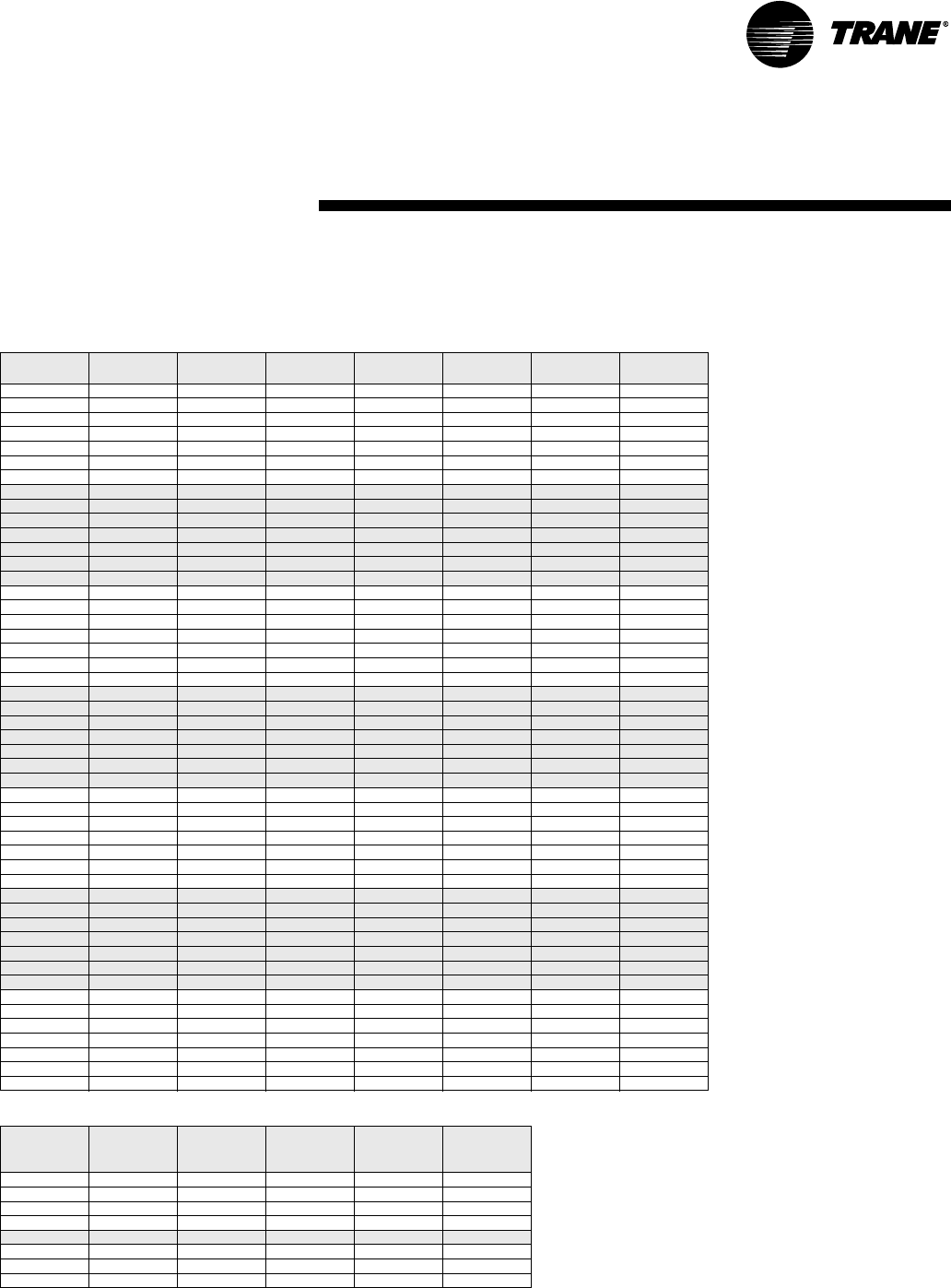
WSHP-PRC001-EN 49
Performance Data
024-Heating
Table P18: GEH/GEV 024 Heating Performance
Heating performance data is tabulated at 68 F DB entering air at ARI/ISO 13256-1 rated CFM. For ARI/ISO 13256-1 certified ratings, see Table P1. See Perfor-
mance correction tables to correct performance at conditions other than those tabulated. Data shown is for unit performance only. Interpolation is permissible.
Extrapolation is not.
Rated GPM: 5.5 Maximum CFM: 608
Rated CFM: 760 Maximum CFM: 912
EWT GPM Htg Cap
Mbtuh
Absorb
Mbtuh
Power
kW
COP LWT Feet
Head
25 3.6 16.1 10.7 1.59 3.0 19.1 5.0
25 4.4 16.5 11.0 1.61 3.0 20.0 7.0
25 5.0 16.8 11.3 1.62 3.0 20.5 8.7
25 5.5 17.0 11.4 1.63 3.1 20.8 10.1
25 5.8 17.1 11.5 1.63 3.1 21.0 10.9
25 6.1 17.2 11.6 1.64 3.1 21.2 11.8
25 6.6 17.4 11.8 1.64 3.1 21.4 13.3
32 3.6 18.5 12.7 1.70 3.2 24.9 4.9
32 4.4 19.0 13.1 1.72 3.2 26.0 6.9
32 5.0 19.2 13.3 1.73 3.3 26.7 8.4
32 5.5 19.4 13.5 1.74 3.3 27.1 9.7
32 5.8 19.5 13.6 1.74 3.3 27.3 10.6
32 6.1 19.6 13.6 1.75 3.3 27.5 11.4
32 6.6 19.8 13.8 1.75 3.3 27.8 12.9
45 3.6 22.8 16.5 1.85 3.6 35.8 4.7
45 4.4 23.4 17.0 1.87 3.7 37.3 6.4
45 5.0 23.6 17.2 1.88 3.7 38.1 7.9
45 5.5 23.8 17.4 1.89 3.7 38.7 9.1
45 5.8 23.9 17.5 1.89 3.7 39.0 9.9
45 6.1 24.0 17.5 1.90 3.7 39.3 10.7
45 6.6 24.2 17.7 1.90 3.7 39.6 12.0
55 3.6 26.1 19.3 1.98 3.9 44.3 4.5
55 4.4 26.7 19.9 2.00 3.9 46.0 6.1
55 5.0 27.0 20.1 2.01 3.9 46.9 7.4
55 5.5 27.2 20.3 2.02 3.9 47.6 8.6
55 5.8 27.3 20.4 2.03 3.9 48.0 9.3
55 6.1 27.4 20.5 2.03 4.0 48.3 10.1
55 6.6 27.5 20.5 2.04 3.9 48.8 11.3
68 3.6 29.9 22.6 2.14 4.1 55.4 4.1
68 4.4 30.5 23.1 2.16 4.1 57.5 5.6
68 5.0 30.8 23.4 2.17 4.2 58.6 6.8
68 5.5 31.0 23.6 2.18 4.2 59.4 7.9
68 5.8 31.1 23.7 2.18 4.2 59.8 8.6
68 6.1 31.2 23.7 2.19 4.2 60.2 9.3
68 6.6 31.4 23.9 2.19 4.2 60.7 10.5
75 3.6 31.7 24.2 2.19 4.2 61.5 3.9
75 4.4 32.3 24.8 2.21 4.3 63.7 5.3
75 5.0 32.6 25.0 2.22 4.3 65.0 6.5
75 5.5 32.8 25.2 2.23 4.3 65.8 7.6
75 5.8 32.9 25.3 2.24 4.3 66.3 8.2
75 6.1 33.0 25.4 2.24 4.3 66.7 8.9
75 6.6 33.2 25.5 2.25 4.3 67.2 10.1
86 3.6 34.1 26.3 2.29 4.4 71.3 3.6
86 4.4 34.8 26.9 2.31 4.4 73.7 4.9
86 5.0 35.1 27.2 2.32 4.4 75.1 6.1
86 5.5 35.3 27.4 2.33 4.4 76.0 7.1
86 5.8 35.4 27.4 2.34 4.4 76.5 7.7
86 6.1 35.5 27.5 2.34 4.4 76.9 8.3
86 6.6 35.6 27.6 2.35 4.4 77.6 9.5
Table P19: 024 Fan Correction Factors
Entering
CFM
Cooling
Capacity
Sensible
Capacity
Cooling
Input
Watts
Heating
Capacity
Heating
Input
Watts
608 0.974 0.892 0.965 0.972 1.032
646 0.980 0.919 0.973 0.979 1.024
684 0.987 0.945 0.981 0.986 1.016
722 0.993 0.972 0.990 0.993 1.008
760 1.000 1.000 1.000 1.000 1.000
836 1.012 1.051 1.020 1.013 0.984
874 1.019 1.078 1.030 1.020 0.976
912 1.025 1.105 1.042 1.027 0.968
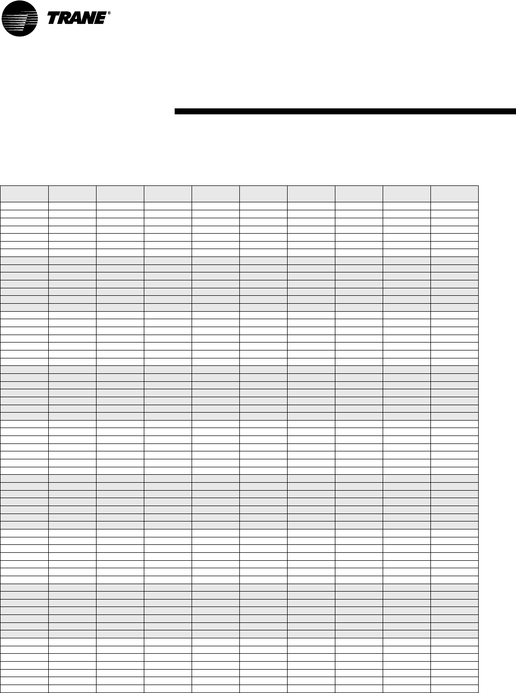
50 WSHP-PRC001-EN
Performance Data
030-Cooling
Table P20: GEH/GEV 030 Cooling Performance
Cooling performance data is tabulated at 80.6 F DB/66.2 F WB entering air at ARI/ISO 13256-1 rated CFM. For ARI/ISO 13256-1 certified ratings, see Table P1.
See Performance correction tables to correct performance at conditions other than those tabulated. Data shown is for unit performance only. Interpolation is
permissible. Extrapolation is not.
Rated GPM: 6.9 Maximum CFM: 720
Rated CFM: 900 Maximum CFM: 1080
EWT GPM Tota l
Mbtuh
Sen
Mbtuh
SHR Power
kW
EER Reject
Mbtuh
LWT Feet
Head
45 4.5 34.3 24.2 0.71 1.78 19.3 40.4 62.9 8.5
45 5.5 34.5 23.9 0.69 1.74 19.8 40.4 59.7 11.5
45 6.2 34.6 23.9 0.69 1.72 20.1 40.5 58.1 13.8
45 6.9 34.7 23.8 0.69 1.71 20.3 40.5 56.7 16.2
45 7.3 34.7 23.8 0.69 1.70 20.4 40.5 56.1 17.7
45 7.6 34.7 23.8 0.69 1.70 20.4 40.5 55.7 18.9
45 8.3 34.8 23.8 0.68 1.69 20.6 40.6 54.8 21.7
55 4.5 32.3 23.2 0.72 1.89 17.1 38.8 72.2 7.8
55 5.5 32.5 23.1 0.71 1.85 17.6 38.8 69.1 10.7
55 6.2 32.6 23.1 0.71 1.83 17.8 38.9 67.5 12.8
55 6.9 32.7 23.2 0.71 1.81 18.1 38.9 66.3 15.1
55 7.3 32.7 23.2 0.71 1.81 18.1 38.9 65.7 16.5
55 7.6 32.7 23.2 0.71 1.80 18.2 38.8 65.2 17.6
55 8.3 32.8 23.2 0.71 1.79 18.3 38.9 64.4 20.3
68 4.5 30.8 22.3 0.72 2.09 14.7 37.9 84.9 7.1
68 5.5 31.0 22.4 0.72 2.05 15.1 38.0 81.8 9.8
68 6.2 31.1 22.5 0.72 2.03 15.3 38.0 80.3 11.8
68 6.9 31.2 22.6 0.72 2.01 15.5 38.1 79.0 14.0
68 7.3 31.2 22.7 0.73 2.01 15.5 38.1 78.4 15.3
68 7.6 31.2 22.7 0.73 2.00 15.6 38.0 78.0 16.4
68 8.3 31.3 22.7 0.73 1.99 15.7 38.1 77.2 18.9
77 4.5 29.4 21.8 0.74 2.25 13.1 37.1 93.5 6.7
77 5.5 29.6 21.9 0.74 2.21 13.4 37.1 90.5 9.3
77 6.2 29.7 22.1 0.74 2.19 13.6 37.2 89.0 11.2
77 6.9 29.8 22.2 0.74 2.17 13.7 37.2 87.8 13.3
77 7.3 29.8 22.2 0.74 2.16 13.8 37.2 87.2 14.6
77 7.6 29.8 22.2 0.74 2.16 13.8 37.2 86.8 15.6
77 8.3 29.9 22.3 0.75 2.14 14.0 37.2 86.0 18.1
86 4.5 27.8 21.3 0.77 2.40 11.6 36.0 102.1 6.4
86 5.5 28.0 21.4 0.76 2.36 11.9 36.1 99.2 8.8
86 6.2 28.1 21.5 0.77 2.34 12.0 36.1 97.7 10.7
86 6.9 28.1 21.6 0.77 2.33 12.1 36.1 96.5 12.8
86 7.3 28.2 21.7 0.77 2.32 12.2 36.1 95.9 14.0
86 7.6 28.2 21.7 0.77 2.31 12.2 36.1 95.5 15.0
86 8.3 28.3 21.7 0.77 2.30 12.3 36.2 94.7 17.5
95 4.5 26.0 20.7 0.80 2.55 10.2 34.7 110.5 6.1
95 5.5 26.1 20.8 0.80 2.51 10.4 34.7 107.7 8.5
95 6.2 26.3 20.9 0.79 2.50 10.5 34.8 106.3 10.3
95 6.9 26.3 21.0 0.80 2.48 10.6 34.8 105.1 12.3
95 7.3 26.3 21.1 0.80 2.48 10.6 34.8 104.6 13.5
95 7.6 26.4 21.1 0.80 2.47 10.7 34.8 104.2 14.5
95 8.3 26.5 21.1 0.80 2.46 10.8 34.9 103.5 16.9
105 4.5 23.9 20.0 0.84 2.71 8.8 33.2 119.8 5.8
105 5.5 24.1 20.1 0.83 2.68 9.0 33.3 117.2 8.1
105 6.2 24.2 20.1 0.83 2.66 9.1 33.3 115.8 9.9
105 6.9 24.3 20.2 0.83 2.65 9.2 33.3 114.7 11.9
105 7.3 24.3 20.2 0.83 2.64 9.2 33.3 114.2 13.1
105 7.6 24.3 20.2 0.83 2.64 9.2 33.3 113.8 14.0
105 8.3 24.4 20.2 0.83 2.62 9.3 33.3 113.1 16.4
115 4.5 22.0 19.1 0.87 2.86 7.7 31.8 129.3 5.5
115 5.5 22.2 19.2 0.86 2.83 7.8 31.9 126.7 7.8
115 6.2 22.3 19.2 0.86 2.82 7.9 31.9 125.4 9.6
115 6.9 22.4 19.3 0.86 2.80 8.0 32.0 124.4 11.5
115 7.3 22.4 19.3 0.86 2.80 8.0 32.0 123.8 12.7
115 7.6 22.4 19.2 0.86 2.79 8.0 31.9 123.5 13.6
115 8.3 22.5 19.2 0.85 2.78 8.1 32.0 122.8 15.9
120 4.5 21.2 18.7 0.88 2.93 7.2 31.2 134.0 5.4
120 5.5 21.4 18.7 0.87 2.90 7.4 31.3 131.5 7.7
120 6.2 21.5 18.8 0.87 2.89 7.4 31.4 130.2 9.4
120 6.9 21.5 18.8 0.87 2.88 7.5 31.3 129.2 11.3
120 7.3 21.6 18.7 0.87 2.87 7.5 31.4 128.7 12.5
120 7.6 21.6 18.7 0.87 2.87 7.5 31.4 128.4 13.4
120 8.3 21.7 18.6 0.86 2.86 7.6 31.5 127.7 15.7

WSHP-PRC001-EN 51
Performance Data
030-Heating
Table P21: GEH/GEV 030 Heating Performance
Heating performance data is tabulated at 68 F DB entering air at ARI/ISO 13256-1 rated CFM. For ARI/ISO 13256-1 certified ratings, see Table P1. See Perfor-
mance correction tables to correct performance at conditions other than those tabulated. Data shown is for unit performance only. Interpolation is permissible.
Extrapolation is not.
Rated GPM: 6.9 Maximum CFM: 720
Rated CFM: 900 Maximum CFM: 1080
EWT GPM Htg Cap
Mbtuh
Absorb
Mbtuh
Power
kW
COP LWT Feet
Head
25 4.5 18.8 12.8 1.77 3.1 19.3 10.2
25 5.5 19.2 13.1 1.78 3.2 20.3 13.8
25 6.2 19.4 13.3 1.78 3.2 20.7 16.3
25 6.9 19.6 13.5 1.79 3.2 21.1 19.1
25 7.3 19.7 13.6 1.79 3.2 21.3 20.5
25 7.6 19.7 13.6 1.79 3.2 21.4 22.0
25 8.3 19.9 13.8 1.79 3.3 21.7 25.0
32 4.5 20.5 14.1 1.87 3.2 25.7 9.5
32 5.5 20.9 14.5 1.88 3.3 26.8 13.0
32 6.2 21.1 14.7 1.89 3.3 27.3 15.5
32 6.9 21.3 14.9 1.89 3.3 27.7 18.1
32 7.3 21.4 15.0 1.89 3.3 27.9 19.5
32 7.6 21.4 14.9 1.90 3.3 28.1 20.9
32 8.3 21.6 15.1 1.90 3.3 28.4 23.9
45 4.5 24.9 18.0 2.03 3.6 37.0 8.5
45 5.5 25.4 18.4 2.05 3.6 38.4 11.7
45 6.2 25.6 18.6 2.06 3.6 39.0 13.9
45 6.9 25.8 18.7 2.07 3.7 39.6 16.3
45 7.3 25.9 18.8 2.07 3.7 39.8 17.6
45 7.6 25.9 18.8 2.07 3.7 40.1 19.0
45 8.3 26.1 19.0 2.08 3.7 40.4 21.8
55 4.5 28.4 21.1 2.15 3.9 45.6 7.9
55 5.5 28.9 21.5 2.17 3.9 47.2 10.8
55 6.2 29.2 21.8 2.18 3.9 48.0 12.9
55 6.9 29.4 21.9 2.19 3.9 48.7 15.2
55 7.3 29.5 22.0 2.19 3.9 48.9 16.5
55 7.6 29.6 22.1 2.20 3.9 49.2 17.7
55 8.3 29.7 22.2 2.20 4.0 49.7 20.4
68 4.5 32.5 24.7 2.30 4.1 57.0 7.1
68 5.5 33.0 25.1 2.32 4.2 58.9 9.9
68 6.2 33.3 25.4 2.33 4.2 59.9 11.9
68 6.9 33.5 25.6 2.33 4.2 60.6 14.1
68 7.3 33.6 25.6 2.34 4.2 61.0 15.2
68 7.6 33.7 25.7 2.34 4.2 61.2 16.4
68 8.3 33.8 25.8 2.35 4.2 61.8 19.0
75 4.5 34.4 26.3 2.37 4.3 63.3 6.8
75 5.5 34.9 26.7 2.39 4.3 65.3 9.5
75 6.2 35.2 27.0 2.40 4.3 66.3 11.4
75 6.9 35.4 27.2 2.41 4.3 67.1 13.6
75 7.3 35.5 27.3 2.41 4.3 67.5 14.7
75 7.6 35.6 27.4 2.41 4.3 67.8 15.9
75 8.3 35.8 27.5 2.42 4.3 68.4 18.4
86 4.5 37.0 28.5 2.48 4.4 73.3 6.4
86 5.5 37.6 29.1 2.50 4.4 75.5 8.9
86 6.2 37.9 29.4 2.50 4.4 76.5 10.8
86 6.9 38.1 29.5 2.51 4.4 77.4 12.9
86 7.3 38.2 29.6 2.51 4.5 77.8 14.0
86 7.6 38.3 29.7 2.52 4.5 78.2 15.1
86 8.3 38.4 29.8 2.52 4.5 78.8 17.5
Table P22: 030 Fan Correction Factors
Entering
CFM
Cooling
Capacity
Sensible
Capacity
Cooling
Input
Watts
Heating
Capacity
Heating
Input
Watts
720 0.974 0.892 0.965 0.972 1.032
765 0.980 0.919 0.973 0.979 1.024
810 0.987 0.945 0.981 0.986 1.016
855 0.993 0.972 0.990 0.993 1.008
900 1.000 1.000 1.000 1.000 1.000
990 1.012 1.051 1.020 1.013 0.984
1035 1.019 1.078 1.030 1.020 0.976
1080 1.025 1.105 1.042 1.027 0.968

52 WSHP-PRC001-EN
Performance Data
036-Cooling
Table P23: GEH/GEV 036 Cooling Performance
Cooling performance data is tabulated at 80.6 F DB/66.2 F WB entering air at ARI/ISO 13256-1 rated CFM. For ARI/ISO 13256-1 certified ratings, see Table P1.
See Performance correction tables to correct performance at conditions other than those tabulated. Data shown is for unit performance only. Interpolation is
permissible. Extrapolation is not.
Rated GPM: 8.3 Maximum CFM: 912
Rated CFM: 1140 Maximum CFM: 1368
EWT GPM Tota l
Mbtuh
Sen
Mbtuh
SHR Power
kW
EER Reject
Mbtuh
LWT Feet
Head
45 5.4 39.3 27.5 0.70 2.22 17.7 46.9 62.4 5.7
45 6.6 39.6 28.0 0.71 2.15 18.4 46.9 59.1 7.8
45 7.5 39.8 28.2 0.71 2.11 18.9 47.0 57.6 9.4
45 8.3 39.9 28.3 0.71 2.09 19.1 47.0 56.3 11.0
45 8.7 39.9 28.4 0.71 2.07 19.3 47.0 55.8 11.9
45 9.1 40.0 28.4 0.71 2.06 19.4 47.0 55.3 12.8
45 10.0 40.2 28.6 0.71 2.04 19.7 47.2 54.5 14.5
55 5.4 37.5 27.0 0.72 2.37 15.8 45.6 71.9 5.4
55 6.6 38.1 27.6 0.72 2.30 16.6 46.0 68.8 7.4
55 7.5 38.4 27.9 0.73 2.27 16.9 46.2 67.4 8.8
55 8.3 38.7 28.1 0.73 2.24 17.3 46.4 66.2 10.4
55 8.7 38.8 28.2 0.73 2.23 17.4 46.4 65.7 11.3
55 9.1 38.9 28.3 0.73 2.22 17.5 46.5 65.2 12.1
55 10.0 39.3 28.5 0.73 2.20 17.9 46.8 64.4 13.8
68 5.4 35.3 26.5 0.75 2.62 13.5 44.2 84.4 5.0
68 6.6 36.2 27.2 0.75 2.56 14.1 44.9 81.6 6.9
68 7.5 36.6 27.6 0.75 2.53 14.5 45.2 80.1 8.2
68 8.3 37.0 27.9 0.75 2.50 14.8 45.5 79.0 9.7
68 8.7 37.2 28.0 0.75 2.49 14.9 45.7 78.5 10.5
68 9.1 37.5 28.2 0.75 2.48 15.1 46.0 78.1 11.3
68 10.0 38.0 28.5 0.75 2.46 15.4 46.4 77.3 12.9
77 5.4 33.9 26.3 0.78 2.81 12.1 43.5 93.2 4.7
77 6.6 34.9 27.1 0.78 2.75 12.7 44.3 90.4 6.5
77 7.5 35.4 27.5 0.78 2.72 13.0 44.7 89.0 7.8
77 8.3 35.9 27.9 0.78 2.70 13.3 45.1 87.9 9.3
77 8.7 36.2 28.0 0.77 2.69 13.5 45.4 87.4 10.0
77 9.1 36.4 28.2 0.77 2.68 13.6 45.6 87.0 10.8
77 10.0 37.0 28.5 0.77 2.66 13.9 46.1 86.3 12.4
86 5.4 32.6 26.1 0.80 3.00 10.9 42.8 101.9 4.5
86 6.6 33.7 27.0 0.80 2.94 11.5 43.7 99.2 6.2
86 7.5 34.3 27.4 0.80 2.92 11.7 44.3 97.9 7.4
86 8.3 34.9 27.9 0.80 2.90 12.0 44.8 96.8 8.8
86 8.7 35.2 28.0 0.80 2.89 12.2 45.1 96.4 9.6
86 9.1 35.4 28.2 0.80 2.88 12.3 45.2 95.9 10.3
86 10.0 36.1 28.6 0.79 2.86 12.6 45.9 95.2 11.9
95 5.4 31.3 25.9 0.83 3.19 9.8 42.2 110.7 4.3
95 6.6 32.5 26.9 0.83 3.14 10.4 43.2 108.1 5.9
95 7.5 33.2 27.4 0.83 3.11 10.7 43.8 106.8 7.1
95 8.3 33.8 27.9 0.83 3.09 10.9 44.4 105.7 8.5
95 8.7 34.1 28.1 0.82 3.09 11.0 44.7 105.3 9.2
95 9.1 34.5 28.3 0.82 3.08 11.2 45.0 104.9 9.9
95 10.0 35.2 28.7 0.82 3.06 11.5 45.6 104.2 11.5
105 5.4 29.9 25.8 0.86 3.39 8.8 41.5 120.5 4.0
105 6.6 31.3 26.8 0.86 3.35 9.3 42.7 118.0 5.6
105 7.5 32.0 27.3 0.85 3.33 9.6 43.4 116.7 6.8
105 8.3 32.7 27.9 0.85 3.31 9.9 44.0 115.7 8.1
105 8.7 33.1 28.1 0.85 3.30 10.0 44.4 115.3 8.9
105 9.1 33.4 28.3 0.85 3.29 10.2 44.6 114.9 9.6
105 10.0 34.2 28.8 0.84 3.28 10.4 45.4 114.2 11.0
115 5.4 28.6 25.6 0.90 3.59 8.0 40.9 130.3 3.9
115 6.6 30.0 26.7 0.89 3.55 8.5 42.1 127.8 5.4
115 7.5 30.9 27.3 0.88 3.53 8.8 43.0 126.6 6.6
115 8.3 31.6 27.8 0.88 3.52 9.0 43.6 125.6 7.9
115 8.7 32.0 28.1 0.88 3.51 9.1 44.0 125.2 8.6
115 9.1 32.4 28.3 0.87 3.50 9.3 44.4 124.8 9.3
115 10.0 33.2 28.9 0.87 3.49 9.5 45.1 124.2 10.7
120 5.4 28.0 25.5 0.91 3.69 7.6 40.6 135.2 3.8
120 6.6 29.5 26.6 0.90 3.65 8.1 42.0 132.8 5.4
120 7.5 30.3 27.2 0.90 3.63 8.3 42.7 131.6 6.5
120 8.3 31.1 27.8 0.89 3.62 8.6 43.5 130.6 7.8
120 8.7 31.5 28.0 0.89 3.61 8.7 43.8 130.2 8.5
120 9.1 31.9 28.3 0.89 3.60 8.9 44.2 129.8 9.2
120 10.0 32.7 28.9 0.88 3.59 9.1 45.0 129.1 10.6

WSHP-PRC001-EN 53
Performance Data
036-Heating
Table P24: GEH/GEV 036 Heating Performance
Heating performance data is tabulated at 68 F DB entering air at ARI/ISO 13256-1 rated CFM. For ARI/ISO 13256-1 certified ratings, see Table P1. See Perfor-
mance correction tables to correct performance at conditions other than those tabulated. Data shown is for unit performance only. Interpolation is permissible.
Extrapolation is not.
Rated GPM: 8.3 Maximum CFM: 912
Rated CFM: 1140 Maximum CFM: 1368
EWT GPM Htg Cap
Mbtuh
Absorb
Mbtuh
Power
kW
COP LWT Feet
Head
25 5.4 20.8 13.7 2.07 2.9 19.9 6.3
25 6.6 21.7 14.5 2.12 3.0 20.6 8.8
25 7.5 22.1 14.8 2.15 3.0 21.0 10.5
25 8.3 22.2 14.8 2.18 3.0 21.4 12.4
25 8.7 22.3 14.8 2.20 3.0 21.6 13.3
25 9.1 22.3 14.8 2.21 3.0 21.8 14.3
25 10.0 22.4 14.8 2.24 2.9 22.0 16.1
32 5.4 23.8 16.3 2.20 3.2 26.0 6.1
32 6.6 24.6 17.0 2.24 3.2 26.9 8.4
32 7.5 25.0 17.3 2.26 3.2 27.4 10.1
32 8.3 25.2 17.4 2.29 3.2 27.8 11.9
32 8.7 25.2 17.4 2.30 3.2 28.0 12.8
32 9.1 25.3 17.4 2.31 3.2 28.2 13.7
32 10.0 25.3 17.3 2.34 3.2 28.5 15.6
45 5.4 30.8 22.2 2.53 3.6 36.8 5.7
45 6.6 31.6 22.9 2.54 3.6 38.1 7.8
45 7.5 32.0 23.3 2.55 3.7 38.8 9.4
45 8.3 32.2 23.5 2.56 3.7 39.3 11.0
45 8.7 32.2 23.4 2.57 3.7 39.6 11.9
45 9.1 32.3 23.5 2.57 3.7 39.8 12.8
45 10.0 32.4 23.6 2.57 3.7 40.3 14.5
55 5.4 35.7 26.6 2.68 3.9 45.2 5.4
55 6.6 36.5 27.3 2.70 4.0 46.8 7.4
55 7.5 36.9 27.7 2.71 4.0 47.6 8.8
55 8.3 37.1 27.8 2.72 4.0 48.3 10.4
55 8.7 37.1 27.8 2.73 4.0 48.6 11.3
55 9.1 37.2 27.9 2.73 4.0 48.9 12.1
55 10.0 37.2 27.9 2.73 4.0 49.4 13.8
68 5.4 41.8 32.0 2.87 4.3 56.1 5.0
68 6.6 42.6 32.7 2.90 4.3 58.1 6.9
68 7.5 43.0 33.0 2.92 4.3 59.1 8.2
68 8.3 43.1 33.1 2.93 4.3 60.0 9.7
68 8.7 43.2 33.2 2.93 4.3 60.4 10.5
68 9.1 43.2 33.2 2.94 4.3 60.7 11.3
68 10.0 43.3 33.3 2.94 4.3 61.3 12.9
75 5.4 45.0 34.9 2.97 4.4 62.0 4.8
75 6.6 45.8 35.6 3.00 4.5 64.3 6.6
75 7.5 46.2 35.9 3.02 4.5 65.4 7.9
75 8.3 46.4 36.1 3.03 4.5 66.3 9.3
75 8.7 46.4 36.0 3.04 4.5 66.7 10.1
75 9.1 46.5 36.1 3.04 4.5 67.1 10.9
75 10.0 46.6 36.2 3.05 4.5 67.7 12.5
86 5.4 48.6 38.0 3.11 4.6 71.9 4.5
86 6.6 49.4 38.7 3.14 4.6 74.3 6.2
86 7.5 49.8 39.0 3.16 4.6 75.5 7.4
86 8.3 50.0 39.2 3.18 4.6 76.5 8.8
86 8.7 50.0 39.1 3.19 4.6 77.0 9.6
86 9.1 50.1 39.2 3.20 4.6 77.4 10.3
86 10.0 50.2 39.2 3.21 4.6 78.1 11.9
Table P25: 036 Fan Correction Factors
Entering
CFM
Cooling
Capacity
Sensible
Capacity
Cooling
Inpu
Watts
Heating
Capacity
Heating
Input
Watts
912 0.974 0.892 0.965 0.972 1.032
969 0.980 0.919 0.973 0.979 1.024
1026 0.987 0.945 0.981 0.986 1.016
1083 0.993 0.972 0.990 0.993 1.008
1140 1.000 1.000 1.000 1.000 1.000
1254 1.012 1.051 1.020 1.013 0.984
1311 1.019 1.078 1.030 1.020 0.976
1368 1.025 1.105 1.042 1.027 0.968

54 WSHP-PRC001-EN
Performance Data
040-Cooling
Table P26: GEV 040 Cooling Performance
Cooling performance data is tabulated at 80.6 F DB/66.2 F WB entering air at ARI/ISO 13256-1 rated CFM. For ARI/ISO 13256-1 certified ratings, see Table P1.
See Performance correction tables to correct performance at conditions other than those tabulated. Data shown is for unit performance only. Interpolation is
permissible. Extrapolation is not.
Rated GPM: 9.2 Maximum CFM: 960
Rated CFM: 1200 Maximum CFM: 1440
EWT GPM Tota l
Mbtuh
Sen
Mbtuh
SHR Power
kW
EER Reject
Mbtuh
LWT Feet
Head
45 6.0 46.2 31.1 0.67 2.45 18.9 54.6 63.2 7.3
45 7.4 46.1 31.3 0.68 2.40 19.2 54.3 59.7 10.3
45 8.3 46.1 31.3 0.68 2.38 19.4 54.2 58.1 12.4
45 9.2 46.0 31.4 0.68 2.37 19.4 54.1 56.8 14.6
45 9.7 46.0 31.4 0.68 2.36 19.5 54.1 56.2 15.8
45 10.1 45.9 31.4 0.68 2.36 19.4 54.0 55.7 16.9
45 11.0 45.9 31.5 0.69 2.35 19.5 53.9 54.8 19.4
55 6.0 44.2 31.0 0.70 2.60 17.0 53.1 72.7 6.8
55 7.4 44.2 31.3 0.71 2.55 17.3 52.9 69.3 9.6
55 8.3 44.3 31.3 0.71 2.53 17.5 52.9 67.8 11.5
55 9.2 44.3 31.3 0.71 2.51 17.6 52.9 66.5 13.6
55 9.7 44.3 31.4 0.71 2.50 17.7 52.8 65.9 14.8
55 10.1 44.3 31.4 0.71 2.50 17.7 52.8 65.5 15.8
55 11.0 44.3 31.5 0.71 2.49 17.8 52.8 64.6 18.1
68 6.0 41.4 30.3 0.73 2.84 14.6 51.1 85.1 6.3
68 7.4 41.7 30.6 0.73 2.79 14.9 51.2 81.9 8.8
68 8.3 41.8 30.6 0.73 2.77 15.1 51.3 80.4 10.6
68 9.2 41.8 30.6 0.73 2.74 15.3 51.2 79.1 12.5
68 9.7 41.9 30.7 0.73 2.73 15.3 51.2 78.6 13.7
68 10.1 41.9 30.7 0.73 2.73 15.3 51.2 78.2 14.6
68 11.0 42.0 30.8 0.73 2.72 15.4 51.3 77.3 16.9
77 6.0 39.4 29.5 0.75 3.03 13.0 49.7 93.6 5.9
77 7.4 39.7 29.8 0.75 2.98 13.3 49.9 90.5 8.4
77 8.3 39.8 29.8 0.75 2.95 13.5 49.9 89.1 10.1
77 9.2 39.9 29.8 0.75 2.93 13.6 49.9 87.9 12.0
77 9.7 40.0 29.9 0.75 2.92 13.7 50.0 87.3 13.1
77 10.1 40.0 29.9 0.75 2.91 13.7 49.9 86.9 14.0
77 11.0 40.1 30.0 0.75 2.90 13.8 50.0 86.1 16.1
86 6.0 37.3 28.6 0.77 3.22 11.6 48.3 102.2 5.6
86 7.4 37.6 28.9 0.77 3.17 11.9 48.4 99.1 8.0
86 8.3 37.7 28.9 0.77 3.14 12.0 48.4 97.7 9.6
86 9.2 37.9 28.9 0.76 3.12 12.1 48.5 96.6 11.4
86 9.7 37.9 29.0 0.77 3.11 12.2 48.5 96.0 12.5
86 10.1 38.0 29.0 0.76 3.10 12.3 48.6 95.7 13.4
86 11.0 38.0 29.1 0.77 3.09 12.3 48.5 94.9 15.5
95 6.0 35.0 27.6 0.79 3.42 10.2 46.7 110.7 5.4
95 7.4 35.3 27.9 0.79 3.37 10.5 46.8 107.7 7.6
95 8.3 35.5 27.9 0.79 3.34 10.6 46.9 106.4 9.2
95 9.2 35.6 27.9 0.78 3.32 10.7 46.9 105.3 11.0
95 9.7 35.7 28.0 0.78 3.31 10.8 47.0 104.7 12.1
95 10.1 35.7 28.0 0.78 3.30 10.8 47.0 104.4 12.9
95 11.0 35.8 28.1 0.78 3.29 10.9 47.0 103.6 15.0
105 6.0 32.3 26.5 0.82 3.63 8.9 44.7 120.0 5.1
105 7.4 32.7 26.8 0.82 3.58 9.1 44.9 117.2 7.3
105 8.3 32.8 26.8 0.82 3.56 9.2 45.0 115.9 8.9
105 9.2 33.0 26.8 0.81 3.54 9.3 45.1 114.9 10.6
105 9.7 33.0 26.9 0.82 3.53 9.3 45.0 114.4 11.6
105 10.1 33.1 26.9 0.81 3.52 9.4 45.1 114.0 12.5
105 11.0 33.1 27.0 0.82 3.50 9.5 45.0 113.2 14.5
115 6.0 29.4 25.6 0.87 3.83 7.7 42.5 129.3 4.9
115 7.4 29.8 25.8 0.87 3.79 7.9 42.7 126.7 7.0
115 8.3 30.0 25.8 0.86 3.76 8.0 42.8 125.4 8.5
115 9.2 30.2 25.9 0.86 3.74 8.1 43.0 124.4 10.2
115 9.7 30.2 25.9 0.86 3.73 8.1 42.9 123.9 11.2
115 10.1 30.3 25.9 0.85 3.73 8.1 43.0 123.6 12.1
115 11.0 30.3 26.0 0.86 3.71 8.2 43.0 122.9 14.1
120 6.0 28.0 25.2 0.90 3.92 7.1 41.4 134.0 4.8
120 7.4 28.4 25.4 0.89 3.88 7.3 41.6 131.4 6.9
120 8.3 28.6 25.4 0.89 3.86 7.4 41.8 130.2 8.4
120 9.2 28.7 25.5 0.89 3.84 7.5 41.8 129.2 10.1
120 9.7 28.8 25.5 0.89 3.83 7.5 41.9 128.7 11.1
120 10.1 28.8 25.6 0.89 3.82 7.5 41.8 128.4 11.9
120 11.0 28.9 25.6 0.89 3.81 7.6 41.9 127.7 13.9

WSHP-PRC001-EN 55
Performance Data
040-Heating
Table P27: GEV 040 Heating Performance
Heating performance data is tabulated at 68 F DB entering air at ARI/ISO 13256-1 rated CFM. For ARI/ISO 13256-1 certified ratings, see Table P1. See Perfor-
mance correction tables to correct performance at conditions other than those tabulated. Data shown is for unit performance only. Interpolation is permissible.
Extrapolation is not.
Rated GPM: 9.2 Maximum CFM: 960
Rated CFM: 1200 Maximum CFM: 1440
EWT GPM Htg Cap
Mbtuh
Absorb
Mbtuh
Power
kW
COP LWT Feet
Head
25 6.0 21.8 13.5 2.43 2.6 20.5 8.3
25 7.4 22.5 14.1 2.45 2.7 21.2 12.0
25 8.3 22.9 14.5 2.46 2.7 21.5 14.6
25 9.2 23.1 14.7 2.46 2.8 21.8 17.3
25 9.7 23.3 14.9 2.47 2.8 21.9 18.8
25 10.1 23.4 15.0 2.47 2.8 22.0 20.0
25 11.0 23.5 15.1 2.47 2.8 22.3 22.9
32 6.0 26.2 17.5 2.55 3.0 26.2 8.0
32 7.4 26.9 18.1 2.58 3.1 27.1 11.4
32 8.3 27.3 18.5 2.59 3.1 27.5 13.7
32 9.2 27.5 18.7 2.59 3.1 27.9 16.2
32 9.7 27.7 18.9 2.59 3.1 28.1 17.6
32 10.1 27.7 18.8 2.60 3.1 28.3 18.8
32 11.0 27.9 19.0 2.60 3.1 28.5 21.5
45 6.0 32.5 22.9 2.80 3.4 37.4 7.3
45 7.4 33.2 23.5 2.83 3.4 38.7 10.3
45 8.3 33.6 23.9 2.84 3.5 39.2 12.4
45 9.2 33.8 24.1 2.85 3.5 39.8 14.6
45 9.7 34.0 24.2 2.86 3.5 40.0 15.8
45 10.1 34.1 24.3 2.86 3.5 40.2 16.9
45 11.0 34.3 24.5 2.86 3.5 40.5 19.4
55 6.0 37.2 27.0 2.99 3.6 46.0 6.8
55 7.4 37.9 27.6 3.03 3.7 47.5 9.6
55 8.3 38.3 27.9 3.04 3.7 48.3 11.5
55 9.2 38.5 28.1 3.05 3.7 48.9 13.6
55 9.7 38.7 28.3 3.05 3.7 49.2 14.8
55 10.1 38.8 28.4 3.06 3.7 49.4 15.8
55 11.0 38.9 28.5 3.06 3.7 49.8 18.1
68 6.0 43.5 32.5 3.22 4.0 57.2 6.3
68 7.4 44.3 33.2 3.26 4.0 59.0 8.8
68 8.3 44.6 33.4 3.28 4.0 59.9 10.6
68 9.2 44.9 33.7 3.29 4.0 60.7 12.5
68 9.7 45.0 33.8 3.29 4.0 61.0 13.7
68 10.1 45.1 33.9 3.29 4.0 61.3 14.6
68 11.0 45.3 34.0 3.30 4.0 61.8 16.9
75 6.0 46.8 35.4 3.34 4.1 63.2 6.0
75 7.4 47.5 36.0 3.38 4.1 65.2 8.5
75 8.3 47.9 36.3 3.39 4.1 66.2 10.2
75 9.2 48.1 36.5 3.41 4.1 67.0 12.1
75 9.7 48.3 36.7 3.41 4.2 67.4 13.2
75 10.1 48.4 36.7 3.42 4.1 67.7 14.1
75 11.0 48.5 36.8 3.42 4.2 68.3 16.3
86 6.0 50.7 38.7 3.51 4.2 73.0 5.6
86 7.4 51.4 39.3 3.55 4.2 75.3 8.0
86 8.3 51.8 39.6 3.57 4.3 76.4 9.6
86 9.2 52.0 39.8 3.58 4.3 77.3 11.4
86 9.7 52.2 39.9 3.59 4.3 77.7 12.5
86 10.1 52.3 40.0 3.59 4.3 78.0 13.4
86 11.0 52.4 40.1 3.60 4.3 78.7 15.5
Table P28: 040 Fan Correction Factors
Entering
CFM
Cooling
Capacity
Sensible
Capacity
Cooling
Input
Watts
Heating
Capacity
Heating
Input
Watts
960 0.974 0.892 0.965 0.972 1.032
1020 0.980 0.919 0.973 0.979 1.024
1080 0.987 0.945 0.981 0.986 1.016
1140 0.993 0.972 0.990 0.993 1.008
1200 1.000 1.000 1.000 1.000 1.000
1320 1.012 1.051 1.020 1.013 0.984
1380 1.019 1.078 1.030 1.020 0.976
1440 1.025 1.105 1.042 1.027 0.968

56 WSHP-PRC001-EN
Performance Data
042-Cooling
Table P29: GEH/GEV 042 Cooling Performance
Cooling performance data is tabulated at 80.6 F DB/66.2 F WB entering air at ARI/ISO 13256-1 rated CFM. For ARI/ISO 13256-1 certified ratings, see Table P1.
See Performance correction tables to correct performance at conditions other than those tabulated. Data shown is for unit performance only. Interpolation is
permissible. Extrapolation is not.
Rated GPM: 9.7 Maximum CFM: 1064
Rated CFM: 1330 Maximum CFM: 1596
EWT GPM Tota l
Mbtuh
Sen
Mbtuh
SHR Power
kW
EER Reject
Mbtuh
LWT Feet
Head
45 6.3 48.0 33.2 0.69 2.70 17.8 57.2 63.2 8.0
45 7.8 48.0 34.1 0.71 2.65 18.1 57.0 59.6 11.2
45 8.7 47.9 34.3 0.72 2.63 18.2 56.9 58.1 13.3
45 9.7 47.8 34.5 0.72 2.62 18.2 56.7 56.7 15.8
45 10.2 47.8 34.6 0.72 2.61 18.3 56.7 56.1 17.2
45 10.7 47.7 34.7 0.73 2.61 18.3 56.6 55.6 18.5
45 11.6 47.7 34.8 0.73 2.61 18.3 56.6 54.8 21.1
55 6.3 45.9 33.5 0.73 2.89 15.9 55.8 72.7 7.4
55 7.8 46.0 34.2 0.74 2.83 16.3 55.7 69.3 10.4
55 8.7 46.1 34.3 0.74 2.81 16.4 55.7 67.8 12.4
55 9.7 46.1 34.4 0.75 2.78 16.6 55.6 66.5 14.8
55 10.2 46.1 34.5 0.75 2.77 16.6 55.6 65.9 16.0
55 10.7 46.1 34.5 0.75 2.77 16.6 55.6 65.4 17.3
55 11.6 46.1 34.7 0.75 2.76 16.7 55.5 64.6 19.8
68 6.3 43.2 33.1 0.77 3.15 13.7 54.0 85.2 6.8
68 7.8 43.4 33.5 0.77 3.08 14.1 53.9 81.8 9.6
68 8.7 43.5 33.6 0.77 3.06 14.2 53.9 80.4 11.5
68 9.7 43.6 33.6 0.77 3.03 14.4 53.9 79.1 13.7
68 10.2 43.6 33.6 0.77 3.02 14.4 53.9 78.6 14.9
68 10.7 43.6 33.7 0.77 3.01 14.5 53.9 78.1 16.1
68 11.6 43.7 33.7 0.77 3.00 14.6 53.9 77.3 18.4
77 6.3 41.1 32.4 0.79 3.35 12.3 52.5 93.7 6.4
77 7.8 41.4 32.7 0.79 3.29 12.6 52.6 90.5 9.1
77 8.7 41.5 32.7 0.79 3.26 12.7 52.6 89.1 10.9
77 9.7 41.6 32.7 0.79 3.24 12.8 52.7 87.9 13.1
77 10.2 41.7 32.7 0.78 3.23 12.9 52.7 87.4 14.2
77 10.7 41.7 32.8 0.79 3.22 13.0 52.7 86.9 15.4
77 11.6 41.8 32.8 0.78 3.20 13.1 52.7 86.1 17.7
86 6.3 38.9 31.5 0.81 3.57 10.9 51.1 102.3 6.1
86 7.8 39.2 31.7 0.81 3.51 11.2 51.2 99.2 8.7
86 8.7 39.4 31.7 0.80 3.48 11.3 51.3 97.8 10.4
86 9.7 39.5 31.7 0.80 3.46 11.4 51.3 96.6 12.5
86 10.2 39.5 31.7 0.80 3.45 11.4 51.3 96.1 13.6
86 10.7 39.6 31.7 0.80 3.44 11.5 51.3 95.6 14.8
86 11.6 39.7 31.8 0.80 3.42 11.6 51.4 94.9 17.0
95 6.3 36.5 30.4 0.83 3.79 9.6 49.4 110.8 5.8
95 7.8 36.9 30.6 0.83 3.73 9.9 49.6 107.8 8.3
95 8.7 37.0 30.6 0.83 3.71 10.0 49.7 106.5 10.0
95 9.7 37.2 30.6 0.82 3.68 10.1 49.8 105.3 12.1
95 10.2 37.2 30.6 0.82 3.67 10.1 49.7 104.8 13.1
95 10.7 37.3 30.6 0.82 3.66 10.2 49.8 104.4 14.3
95 11.6 37.3 30.7 0.82 3.65 10.2 49.8 103.6 16.5
105 6.3 33.7 29.1 0.86 4.02 8.4 47.4 120.2 5.5
105 7.8 34.1 29.4 0.86 3.97 8.6 47.7 117.3 8.0
105 8.7 34.3 29.4 0.86 3.95 8.7 47.8 116.1 9.6
105 9.7 34.4 29.4 0.85 3.92 8.8 47.8 114.9 11.6
105 10.2 34.5 29.4 0.85 3.91 8.8 47.8 114.5 12.7
105 10.7 34.5 29.4 0.85 3.90 8.8 47.8 114.0 13.8
105 11.6 34.6 29.5 0.85 3.89 8.9 47.9 113.3 16.0
115 6.3 30.7 27.9 0.91 4.24 7.2 45.2 129.5 5.3
115 7.8 31.2 28.3 0.91 4.20 7.4 45.5 126.8 7.7
115 8.7 31.3 28.3 0.90 4.17 7.5 45.5 125.6 9.3
115 9.7 31.5 28.4 0.90 4.15 7.6 45.7 124.5 11.2
115 10.2 31.5 28.4 0.90 4.14 7.6 45.6 124.0 12.3
115 10.7 31.6 28.5 0.90 4.13 7.7 45.7 123.6 13.4
115 11.6 31.7 28.6 0.90 4.12 7.7 45.8 123.0 15.5
120 6.3 29.2 27.4 0.94 4.35 6.7 44.1 134.1 5.2
120 7.8 29.7 27.8 0.94 4.31 6.9 44.4 131.5 7.5
120 8.7 29.8 27.9 0.94 4.28 7.0 44.4 130.3 9.1
120 9.7 30.0 28.0 0.93 4.26 7.0 44.5 129.3 11.1
120 10.2 30.0 28.0 0.93 4.25 7.1 44.5 128.8 12.1
120 10.7 30.1 28.1 0.93 4.24 7.1 44.6 128.4 13.2
120 11.6 30.2 28.2 0.93 4.23 7.1 44.6 127.8 15.3

WSHP-PRC001-EN 57
Performance Data
042-Heating
Table P30: GEH/GEV 042 Heating Performance
Heating performance data is tabulated at 68 F DB entering air at ARI/ISO 13256-1 rated CFM. For ARI/ISO 13256-1 certified ratings, see Table P1. See Perfor-
mance correction tables to correct performance at conditions other than those tabulated. Data shown is for unit performance only. Interpolation is permissible.
Extrapolation is not.
Rated GPM: 9.7 Maximum CFM: 1064
Rated CFM: 1330 Maximum CFM: 1596
EWT GPM Htg Cap
Mbtuh
Absorb
Mbtuh
Power
kW
COP LWT Feet
Head
25 6.3 23.4 14.6 2.57 2.7 20.4 9.0
25 7.8 24.6 15.7 2.61 2.8 21.0 13.2
25 8.7 24.9 15.9 2.63 2.8 21.3 15.8
25 9.7 25.1 16.1 2.64 2.8 21.7 18.8
25 10.2 25.2 16.2 2.64 2.8 21.8 20.4
25 10.7 25.2 16.2 2.64 2.8 22.0 22.0
25 11.6 25.4 16.4 2.65 2.8 22.2 25.0
32 6.3 28.1 18.9 2.71 3.0 26.0 8.7
32 7.8 29.3 19.9 2.75 3.1 26.9 12.4
32 8.7 29.6 20.2 2.76 3.1 27.4 14.8
32 9.7 29.9 20.5 2.77 3.2 27.8 17.6
32 10.2 29.9 20.4 2.78 3.2 28.0 19.1
32 10.7 29.9 20.4 2.78 3.2 28.2 20.6
32 11.6 30.2 20.7 2.79 3.2 28.4 23.4
45 6.3 35.0 24.8 2.99 3.4 37.1 8.0
45 7.8 36.1 25.8 3.03 3.5 38.4 11.2
45 8.7 36.5 26.1 3.05 3.5 39.0 13.3
45 9.7 36.7 26.3 3.06 3.5 39.6 15.8
45 10.2 36.7 26.3 3.06 3.5 39.9 17.2
45 10.7 36.8 26.4 3.06 3.5 40.1 18.5
45 11.6 37.0 26.5 3.07 3.5 40.4 21.1
55 6.3 39.9 28.9 3.22 3.6 45.8 7.4
55 7.8 41.1 30.0 3.26 3.7 47.3 10.4
55 8.7 41.4 30.2 3.28 3.7 48.1 12.4
55 9.7 41.7 30.5 3.29 3.7 48.7 14.8
55 10.2 41.7 30.5 3.29 3.7 49.0 16.0
55 10.7 41.7 30.5 3.29 3.7 49.3 17.3
55 11.6 42.0 30.7 3.30 3.7 49.7 19.8
68 6.3 46.8 34.9 3.48 3.9 56.9 6.8
68 7.8 47.9 35.9 3.52 4.0 58.8 9.6
68 8.7 48.3 36.3 3.53 4.0 59.7 11.5
68 9.7 48.5 36.4 3.55 4.0 60.5 13.7
68 10.2 48.5 36.4 3.55 4.0 60.9 14.9
68 10.7 48.6 36.5 3.55 4.0 61.2 16.1
68 11.6 48.8 36.7 3.56 4.0 61.7 18.4
75 6.3 50.3 38.0 3.60 4.1 62.9 6.5
75 7.8 51.5 39.1 3.64 4.1 65.0 9.2
75 8.7 51.8 39.3 3.66 4.1 65.9 11.0
75 9.7 52.0 39.5 3.67 4.2 66.8 13.2
75 10.2 52.1 39.6 3.67 4.2 67.2 14.3
75 10.7 52.1 39.6 3.67 4.2 67.6 15.5
75 11.6 52.3 39.7 3.68 4.2 68.1 17.8
85 6.3 54.2 41.3 3.78 4.2 71.8 6.1
85 7.8 55.4 42.4 3.82 4.2 74.1 8.7
85 8.7 55.7 42.6 3.84 4.2 75.2 10.5
85 9.7 55.9 42.8 3.85 4.3 76.2 12.6
85 10.2 56.0 42.9 3.85 4.3 76.6 13.7
85 10.7 56.0 42.9 3.85 4.3 77.0 14.9
85 11.6 56.3 43.1 3.86 4.3 77.5 17.1
Table P31: 042 Fan Correction Factors
Entering
CFM
Cooling
Capacity
Sensible
Capacity
Cooling
Input
Watts
Heating
Capacity
Heating
Input
Watts
1064 0.974 0.892 0.965 0.972 1.032
1131 0.980 0.919 0.973 0.979 1.024
1197 0.987 0.945 0.981 0.986 1.016
1264 0.993 0.972 0.991 0.993 1.008
1330 1.000 1.000 1.000 1.000 1.000
1463 1.012 1.051 1.020 1.013 0.984
1529 1.019 1.078 1.030 1.020 0.976
1596 1.025 1.105 1.042 1.027 0.968

58 WSHP-PRC001-EN
Performance Data
048-Cooling
Table P32: GEH/GEV 048 Cooling Performance
Cooling performance data is tabulated at 80.6 F DB/66.2 F WB entering air at ARI/ISO 13256-1 rated CFM. For ARI/ISO 13256-1 certified ratings, see Table P1.
See Performance correction tables to correct performance at conditions other than those tabulated. Data shown is for unit performance only. Interpolation is
permissible. Extrapolation is not.
Rated GPM: 11 Maximum CFM: 1216
Rated CFM: 1520 Maximum CFM: 1824
EWT GPM Tota l
Mbtuh
Sen
Mbtuh
SHR Power
kW
EER Reject
Mbtuh
LWT Feet
Head
45 7.2 56.8 39.9 0.70 3.33 17.1 68.2 63.9 5.6
45 8.8 57.4 40.1 0.70 3.25 17.7 68.5 60.6 7.6
45 9.9 57.7 40.2 0.70 3.21 18.0 68.7 58.9 9.1
45 11.0 57.9 40.4 0.70 3.18 18.2 68.8 57.5 10.8
45 11.6 58.1 40.4 0.70 3.16 18.4 68.9 56.9 11.7
45 12.1 58.2 40.4 0.69 3.15 18.5 69.0 56.4 12.6
45 13.2 58.2 40.5 0.70 3.13 18.6 68.9 55.4 14.4
55 7.2 54.7 39.4 0.72 3.58 15.3 66.9 73.6 5.2
55 8.8 55.4 39.6 0.71 3.50 15.8 67.4 70.3 7.2
55 9.9 55.6 39.7 0.71 3.46 16.1 67.4 68.6 8.6
55 11.0 55.9 39.8 0.71 3.43 16.3 67.6 67.3 10.2
55 11.6 56.0 39.9 0.71 3.42 16.4 67.7 66.7 11.2
55 12.1 56.1 39.9 0.71 3.41 16.5 67.7 66.2 12.0
55 13.2 56.2 40.0 0.71 3.38 16.6 67.7 65.3 13.8
68 7.2 51.2 37.9 0.74 3.90 13.1 64.5 85.9 4.9
68 8.8 51.9 38.1 0.73 3.82 13.6 64.9 82.8 6.7
68 9.9 52.1 38.2 0.73 3.78 13.8 65.0 81.2 8.1
68 11.0 52.3 38.3 0.73 3.75 13.9 65.1 79.9 9.7
68 11.6 52.5 38.4 0.73 3.73 14.1 65.2 79.3 10.6
68 12.1 52.6 38.4 0.73 3.72 14.1 65.3 78.8 11.3
68 13.2 52.6 38.5 0.73 3.70 14.2 65.2 77.9 13.1
77 7.2 48.6 36.8 0.76 4.15 11.7 62.8 94.5 4.7
77 8.8 49.3 37.0 0.75 4.07 12.1 63.2 91.4 6.5
77 9.9 49.5 37.1 0.75 4.03 12.3 63.3 89.8 7.9
77 11.0 49.8 37.2 0.75 4.00 12.5 63.5 88.6 9.4
77 11.6 49.9 37.3 0.75 3.98 12.5 63.5 88.0 10.2
77 12.1 50.0 37.3 0.75 3.97 12.6 63.6 87.5 11.0
77 13.2 50.1 37.4 0.75 3.95 12.7 63.6 86.7 12.8
86 7.2 46.1 35.9 0.78 4.42 10.4 61.2 103.1 4.6
86 8.8 46.8 36.1 0.77 4.34 10.8 61.6 100.1 6.3
86 9.9 47.0 36.3 0.77 4.30 10.9 61.7 98.5 7.7
86 11.0 47.3 36.4 0.77 4.27 11.1 61.9 97.3 9.1
86 11.6 47.4 36.4 0.77 4.25 11.2 61.9 96.7 10.0
86 12.1 47.5 36.5 0.77 4.24 11.2 62.0 96.3 10.7
86 13.2 47.6 36.5 0.77 4.22 11.3 62.0 95.4 12.5
95 7.2 43.6 35.3 0.81 4.69 9.3 59.6 111.7 4.5
95 8.8 44.2 35.5 0.80 4.62 9.6 60.0 108.7 6.2
95 9.9 44.5 35.6 0.80 4.57 9.7 60.1 107.2 7.5
95 11.0 44.7 35.7 0.80 4.54 9.8 60.2 106.0 8.9
95 11.6 44.9 35.8 0.80 4.53 9.9 60.4 105.5 9.8
95 12.1 45.0 35.8 0.80 4.52 10.0 60.4 105.0 10.5
95 13.2 45.0 35.9 0.80 4.49 10.0 60.3 104.2 12.2
105 7.2 40.6 34.8 0.86 4.99 8.1 57.6 121.1 4.4
105 8.8 41.3 35.1 0.85 4.92 8.4 58.1 118.3 6.0
105 9.9 41.5 35.2 0.85 4.88 8.5 58.2 116.8 7.3
105 11.0 41.7 35.3 0.85 4.84 8.6 58.2 115.7 8.7
105 11.6 41.9 35.3 0.84 4.83 8.7 58.4 115.1 9.6
105 12.1 42.0 35.4 0.84 4.82 8.7 58.5 114.7 10.3
105 13.2 42.1 35.4 0.84 4.79 8.8 58.5 113.9 12.0
115 7.2 37.4 34.3 0.92 5.31 7.0 55.5 130.6 4.3
115 8.8 38.1 34.5 0.91 5.23 7.3 56.0 127.8 5.9
115 9.9 38.4 34.6 0.90 5.19 7.4 56.1 126.5 7.2
115 11.0 38.6 34.7 0.90 5.16 7.5 56.2 125.3 8.6
115 11.6 38.7 34.8 0.90 5.15 7.5 56.3 124.8 9.4
115 12.1 38.8 34.8 0.90 5.14 7.5 56.3 124.4 10.1
115 13.2 38.9 34.9 0.90 5.11 7.6 56.3 123.6 11.8
120 7.2 35.8 33.9 0.95 5.50 6.5 54.6 135.3 4.2
120 8.8 36.5 34.1 0.93 5.42 6.7 55.0 132.6 5.8
120 9.9 36.7 34.2 0.93 5.38 6.8 55.1 131.3 7.1
120 11.0 37.0 34.3 0.93 5.35 6.9 55.3 130.2 8.5
120 11.6 37.1 34.4 0.93 5.33 7.0 55.3 129.6 9.3
120 12.1 37.2 34.4 0.92 5.32 7.0 55.4 129.3 10.1
120 13.2 37.3 34.5 0.92 5.30 7.0 55.4 128.5 11.8

WSHP-PRC001-EN 59
Performance Data
048-Heating
Table P33: GEH/GEV 048 Heating Performance
Heating performance data is tabulated at 68 F DB entering air at ARI/ISO 13256-1 rated CFM. For ARI/ISO 13256-1 certified ratings, see Table P1. See Perfor-
mance correction tables to correct performance at conditions other than those tabulated. Data shown is for unit performance only. Interpolation is permissible.
Extrapolation is not.
Rated GPM: 11 Maximum CFM: 1216
Rated CFM: 1520 Maximum CFM: 1824
EWT GPM Htg Cap
Mbtuh
Absorb
Mbtuh
Power
kW
COP LWT Feet
Head
25 7.2 23.2 13.0 3.00 2.3 21.4 6.5
25 8.8 23.9 13.6 3.03 2.3 21.9 8.8
25 9.9 24.4 14.0 3.05 2.3 22.2 10.5
25 11.0 24.7 14.3 3.06 2.4 22.4 12.3
25 11.6 24.8 14.4 3.06 2.4 22.5 13.3
25 12.1 24.9 14.4 3.07 2.4 22.6 14.2
25 13.2 25.1 14.6 3.08 2.4 22.8 16.2
32 7.2 33.6 22.0 3.39 2.9 25.9 6.1
32 8.8 34.4 22.8 3.41 3.0 26.8 8.4
32 9.9 34.8 23.1 3.43 3.0 27.3 10.0
32 11.0 35.1 23.4 3.44 3.0 27.8 11.7
32 11.6 35.3 23.6 3.44 3.0 27.9 12.7
32 12.1 35.4 23.6 3.45 3.0 28.1 13.5
32 13.2 35.5 23.7 3.46 3.0 28.4 15.5
45 7.2 42.3 29.7 3.68 3.4 36.7 5.6
45 8.8 43.1 30.4 3.71 3.4 38.1 7.6
45 9.9 43.5 30.8 3.72 3.4 38.8 9.1
45 11.0 43.8 31.1 3.73 3.4 39.4 10.8
45 11.6 44.0 31.2 3.74 3.4 39.6 11.7
45 12.1 44.1 31.3 3.74 3.5 39.8 12.6
45 13.2 44.2 31.4 3.75 3.5 40.2 14.4
55 7.2 48.1 34.8 3.89 3.6 45.3 5.2
55 8.8 48.8 35.5 3.91 3.7 46.9 7.2
55 9.9 49.2 35.8 3.93 3.7 47.8 8.6
55 11.0 49.6 36.2 3.94 3.7 48.4 10.2
55 11.6 49.7 36.2 3.95 3.7 48.8 11.2
55 12.1 49.8 36.3 3.95 3.7 49.0 12.0
55 13.2 50.0 36.5 3.96 3.7 49.5 13.8
68 7.2 55.5 41.3 4.17 3.9 56.5 4.9
68 8.8 56.2 41.9 4.19 3.9 58.5 6.7
68 9.9 56.7 42.3 4.21 3.9 59.4 8.1
68 11.0 57.0 42.6 4.22 4.0 60.2 9.7
68 11.6 57.1 42.7 4.22 4.0 60.6 10.6
68 12.1 57.3 42.9 4.23 4.0 60.9 11.3
68 13.2 57.4 42.9 4.24 4.0 61.5 13.1
75 7.2 58.3 43.7 4.27 4.0 62.8 4.8
75 8.8 59.0 44.3 4.30 4.0 64.9 6.6
75 9.9 59.5 44.8 4.31 4.0 65.9 7.9
75 11.0 59.8 45.1 4.32 4.1 66.8 9.4
75 11.6 59.9 45.1 4.33 4.1 67.2 10.3
75 12.1 60.0 45.2 4.33 4.1 67.5 11.1
75 13.2 60.2 45.4 4.34 4.1 68.1 12.8
86 7.2 61.3 46.4 4.37 4.1 73.1 4.6
86 8.8 62.0 47.0 4.40 4.1 75.3 6.3
86 9.9 62.5 47.5 4.41 4.2 76.4 7.7
86 11.0 62.8 47.7 4.42 4.2 77.3 9.1
86 11.6 62.9 47.8 4.43 4.2 77.7 10.0
86 12.1 63.0 47.9 4.43 4.2 78.1 10.7
86 13.2 63.2 48.0 4.45 4.2 78.7 12.5
Table P34: 048 Fan Correction Factors
Entering
CFM
Cooling
Capacity
Sensible
Capacity
Cooling
Input
Watts
Heating
Capacity
Heating
Input
Watts
1216 0.974 0.892 0.965 0.972 1.032
1292 0.980 0.919 0.973 0.979 1.024
1368 0.987 0.945 0.981 0.986 1.016
1444 0.993 0.972 0.991 0.993 1.008
1520 1.000 1.000 1.000 1.000 1.000
1672 1.012 1.051 1.020 1.013 0.984
1748 1.019 1.078 1.030 1.020 0.976
1824 1.025 1.105 1.042 1.027 0.968

60 WSHP-PRC001-EN
Performance Data
060-Cooling
Table P35: GEH/GEV 060 Cooling Performance
Cooling performance data is tabulated at 80.6 F DB/66.2 F WB entering air at ARI/ISO 13256-1 rated CFM. For ARI/ISO 13256-1 certified ratings, see Table P1.
See Performance correction tables to correct performance at conditions other than those tabulated. Data shown is for unit performance only. Interpolation is
permissible. Extrapolation is not.
Rated GPM: 14.5 Maximum CFM: 1520
Rated CFM: 1900 Maximum CFM: 2280
EWT GPM Tota l
Mbtuh
Sen
Mbtuh
SHR Power
kW
EER Reject
Mbtuh
LWT Feet
Head
45 9.4 66.5 49.2 0.74 3.71 17.9 79.2 61.8 8.0
45 11.6 65.7 48.6 0.74 3.65 18.0 78.2 58.5 11.0
45 13.1 65.3 48.4 0.74 3.61 18.1 77.6 56.8 13.1
45 14.5 65.1 48.3 0.74 3.59 18.1 77.4 55.7 15.3
45 15.2 64.9 48.2 0.74 3.58 18.1 77.1 55.1 16.5
45 16.0 64.8 48.1 0.74 3.57 18.2 77.0 54.6 17.9
45 17.4 64.7 47.9 0.74 3.56 18.2 76.9 53.8 20.6
55 9.4 64.6 47.8 0.74 3.97 16.3 78.2 71.6 7.5
55 11.6 64.3 47.7 0.74 3.89 16.5 77.6 68.4 10.3
55 13.1 64.2 47.8 0.74 3.85 16.7 77.3 66.8 12.3
55 14.5 64.2 47.8 0.74 3.82 16.8 77.2 65.7 14.4
55 15.2 64.2 47.8 0.74 3.81 16.9 77.2 65.2 15.6
55 16.0 64.2 47.8 0.74 3.80 16.9 77.2 64.6 16.9
55 17.4 64.3 47.7 0.74 3.78 17.0 77.2 63.9 19.5
68 9.4 61.7 46.4 0.75 4.39 14.1 76.7 84.3 6.9
68 11.6 61.8 46.8 0.76 4.29 14.4 76.4 81.2 9.6
68 13.1 61.9 47.1 0.76 4.24 14.6 76.4 79.7 11.5
68 14.5 62.0 47.2 0.76 4.21 14.7 76.4 78.5 13.5
68 15.2 62.1 47.3 0.76 4.19 14.8 76.4 78.1 14.6
68 16.0 62.2 47.3 0.76 4.18 14.9 76.5 77.6 15.9
68 17.4 62.4 47.3 0.76 4.16 15.0 76.6 76.8 18.3
77 9.4 59.5 45.6 0.77 4.74 12.6 75.7 93.1 6.5
77 11.6 59.7 46.2 0.77 4.63 12.9 75.5 90.1 9.1
77 13.1 59.9 46.5 0.78 4.58 13.1 75.5 88.6 11.0
77 14.5 60.1 46.8 0.78 4.53 13.3 75.6 87.4 13.0
77 15.2 60.2 46.8 0.78 4.52 13.3 75.6 87.0 14.0
77 16.0 60.3 46.9 0.78 4.50 13.4 75.7 86.5 15.3
77 17.4 60.5 46.9 0.78 4.47 13.5 75.8 85.7 17.7
86 9.4 57.1 44.8 0.78 5.14 11.1 74.6 101.9 6.2
86 11.6 57.4 45.5 0.79 5.02 11.4 74.5 98.9 8.8
86 13.1 57.7 45.9 0.80 4.96 11.6 74.6 97.4 10.6
86 14.5 57.9 46.1 0.80 4.91 11.8 74.7 96.3 12.5
86 15.2 58.0 46.2 0.80 4.89 11.9 74.7 95.9 13.6
86 16.0 58.1 46.3 0.80 4.87 11.9 74.7 95.4 14.8
86 17.4 58.3 46.3 0.79 4.84 12.0 74.8 94.6 17.1
95 9.4 54.6 44.0 0.81 5.60 9.8 73.7 110.8 5.9
95 11.6 55.0 44.7 0.81 5.47 10.1 73.7 107.8 8.5
95 13.1 55.2 45.0 0.82 5.40 10.2 73.6 106.3 10.3
95 14.5 55.5 45.2 0.81 5.34 10.4 73.7 105.2 12.1
95 15.2 55.6 45.3 0.81 5.32 10.5 73.8 104.8 13.2
95 16.0 55.7 45.3 0.81 5.30 10.5 73.8 104.3 14.4
95 17.4 55.8 45.3 0.81 5.27 10.6 73.8 103.5 16.7
105 9.4 51.8 42.9 0.83 6.19 8.4 72.9 120.6 5.6
105 11.6 52.2 43.5 0.83 6.04 8.6 72.8 117.7 8.1
105 13.1 52.4 43.7 0.83 5.96 8.8 72.7 116.2 9.9
105 14.5 52.6 43.8 0.83 5.89 8.9 72.7 115.1 11.8
105 15.2 52.7 43.8 0.83 5.87 9.0 72.7 114.6 12.8
105 16.0 52.8 43.8 0.83 5.84 9.0 72.7 114.2 14.0
105 17.4 52.9 43.7 0.83 5.80 9.1 72.7 113.4 16.2
115 9.4 48.9 41.6 0.85 6.85 7.1 72.3 130.5 5.4
115 11.6 49.3 41.8 0.85 6.68 7.4 72.1 127.6 7.9
115 13.1 49.5 41.8 0.84 6.59 7.5 72.0 126.1 9.6
115 14.5 49.7 41.8 0.84 6.52 7.6 72.0 125.0 11.5
115 15.2 49.7 41.7 0.84 6.49 7.7 71.9 124.6 12.4
115 16.0 49.8 41.7 0.84 6.47 7.7 71.9 124.1 13.6
115 17.4 49.9 41.5 0.83 6.42 7.8 71.8 123.3 15.8
120 9.4 47.4 40.7 0.86 7.21 6.6 72.0 135.5 5.3
120 11.6 47.8 40.7 0.85 7.04 6.8 71.8 132.5 7.8
120 13.1 48.0 40.6 0.85 6.94 6.9 71.7 131.1 9.5
120 14.5 48.2 40.5 0.84 6.87 7.0 71.7 130.0 11.3
120 15.2 48.2 40.4 0.84 6.84 7.0 71.5 129.5 12.3
120 16.0 48.3 40.3 0.83 6.81 7.1 71.5 129.0 13.4
120 17.4 48.3 40.1 0.83 6.76 7.1 71.4 128.3 15.6

WSHP-PRC001-EN 61
Performance Data
060-Heating
Table P36: GEH/GEV 060 Heating Performance
Heating performance data is tabulated at 68 F DB entering air at ARI/ISO 13256-1 rated CFM. For ARI/ISO 13256-1 certified ratings, see Table P1. See Perfor-
mance correction tables to correct performance at conditions other than those tabulated. Data shown is for unit performance only. Interpolation is permissible.
Extrapolation is not.
Rated GPM: 14.5 Maximum CFM: 1520
Rated CFM: 1900 Maximum CFM: 2280
EWT GPM Htg Cap
Mbtuh
Absorb
Mbtuh
Power
kW
COP LWT Feet
Head
25 9.4 40.7 26.1 4.28 2.8 19.5 9.6
25 11.6 41.9 27.2 4.30 2.9 20.3 12.6
25 13.1 42.2 27.5 4.31 2.9 20.8 15.0
25 14.5 42.3 27.6 4.31 2.9 21.2 17.6
25 15.2 42.3 27.6 4.31 2.9 21.4 19.0
25 16.0 42.3 27.6 4.31 2.9 21.5 20.5
25 17.4 42.3 27.6 4.32 2.9 21.8 23.7
32 9.4 45.2 30.3 4.36 3.0 25.6 8.9
32 11.6 46.6 31.7 4.38 3.1 26.5 12.0
32 13.1 47.0 32.0 4.39 3.1 27.1 14.2
32 14.5 47.2 32.2 4.40 3.1 27.6 16.7
32 15.2 47.2 32.2 4.41 3.1 27.8 18.0
32 16.0 47.3 32.3 4.41 3.1 28.0 19.4
32 17.4 47.4 32.4 4.41 3.1 28.3 22.4
45 9.4 54.7 39.1 4.58 3.5 36.7 8.1
45 11.6 56.1 40.4 4.61 3.6 38.0 11.0
45 13.1 56.6 40.8 4.62 3.6 38.7 13.0
45 14.5 56.9 41.1 4.63 3.6 39.3 15.3
45 15.2 57.1 41.3 4.64 3.6 39.6 16.6
45 16.0 57.2 41.4 4.64 3.6 39.8 17.8
45 17.4 57.5 41.6 4.65 3.6 40.2 20.6
55 9.4 62.2 45.9 4.78 3.8 45.3 7.5
55 11.6 63.6 47.2 4.81 3.9 46.9 10.3
55 13.1 64.1 47.7 4.82 3.9 47.7 12.3
55 14.5 64.6 48.1 4.84 3.9 48.4 14.4
55 15.2 64.7 48.2 4.84 3.9 48.7 15.6
55 16.0 64.9 48.4 4.85 3.9 48.9 16.9
55 17.4 65.3 48.7 4.86 3.9 49.4 19.5
68 9.4 71.6 54.4 5.04 4.2 56.4 6.9
68 11.6 72.9 55.6 5.08 4.2 58.4 9.6
68 13.1 73.4 56.0 5.10 4.2 59.4 11.4
68 14.5 73.8 56.4 5.11 4.2 60.2 13.5
68 15.2 74.1 56.6 5.12 4.2 60.6 14.6
68 16.0 74.3 56.8 5.12 4.3 60.9 15.8
68 17.4 74.7 57.2 5.13 4.3 61.4 18.3
75 9.4 76.2 58.5 5.18 4.3 62.6 6.6
75 11.6 77.3 59.5 5.21 4.3 64.7 9.2
75 13.1 77.8 60.0 5.23 4.4 65.8 11.1
75 14.5 78.2 60.3 5.25 4.4 66.7 13.1
75 15.2 78.5 60.6 5.25 4.4 67.0 14.2
75 16.0 78.7 60.8 5.26 4.4 67.4 15.3
75 17.4 79.2 61.2 5.27 4.4 67.9 17.8
86 9.4 82.1 63.8 5.36 4.5 72.4 6.2
86 11.6 83.0 64.6 5.39 4.5 74.8 8.8
86 13.1 83.4 64.9 5.41 4.5 76.0 10.6
86 14.5 83.8 65.3 5.43 4.5 77.0 12.5
86 15.2 84.0 65.5 5.43 4.5 77.4 13.6
86 16.0 84.3 65.7 5.44 4.5 77.7 14.7
86 17.4 84.8 66.2 5.45 4.6 78.4 17.1
Table P37: 060 Fan Correction Factors
Entering
CFM
Cooling
Capacity
Sensible
Capacity
Cooling
Input
Watts
Heating
Capacity
Heating
Input
Watts
1520 0.974 0.892 0.965 0.972 1.032
1615 0.980 0.919 0.973 0.979 1.024
1710 0.987 0.945 0.981 0.986 1.016
1805 0.993 0.972 0.990 0.993 1.008
1900 1.000 1.000 1.000 1.000 1.000
2090 1.012 1.051 1.020 1.013 0.984
2185 1.019 1.078 1.030 1.020 0.976
2280 1.025 1.105 1.042 1.027 0.968
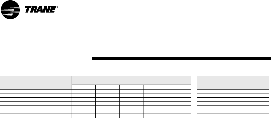
62 WSHP-PRC001-EN
Table P38: 006-060 Correction Factors for Variation in Entering Air Temperature
* = Sensible equals total capacity
Cooling
Entering
Air WB F
Cooling
Capacity
Cooling
Input
Watts
Sensible vs Entering Dry Bulb
Multipliers
Heating
Entering
Air DB F
Heating
Capacity
Heating
Input
Watts
65.6 70.6 75.6 80.6 85.6
49.40.7220.893***** 53.01.0300.878
56.3 0.836 0.937 0.799 0.964 * * * 58.0 1.020 0.919
60.3 0.903 0.963 0.641 0.841 1.016 1.097 * 63.0 1.010 0.959
63.2 0.951 0.981 0.504 0.728 0.924 1.097 * 68.0 1.000 1.000
66.2 1.000 1.000 0.593 0.809 1.000 1.169 73.0 0.990 1.041
72.1 1.098 1.038 0.538 0.761 0.960 78.0 0.980 1.081
77.1 1.181 1.069 0.519 0.741 83.0 0.970 1.122
Performance Data
Correction Factors
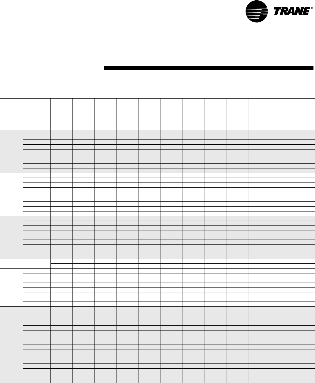
WSHP-PRC001-EN 63
Performance Data
Electrical
E1-Electrical performance
Model No. Volts Total
FLA
Comp
RLA
(ea)
Comp
LRA
(ea)
No. of
Compres.
Cmp
MCC
Blower
Motor
FLA
Blower
Motor
HP
Fan
Motor
Num
Minimum
Circuit
Ampacity
Maximum
Overcur-
rent
Protec-
tive
Device
Electric
Heat
kW
Electric
Heat
Amps
006 115/60/1 6.8 5.70 36.2 19.1 1.20 1/12 18.3 15 0 0
208/60/1 3.4 2.80 17.7 14.6 0.60 1/12 14.1 15 0 0
208/60/1 4.48 2.8 17.7 14.6 0.60 1/12 15.6 15 0.82 3.9
230/60/1 3.4 2.80 17.7 14.6 0.60 1/12 14.1 15 0 0
230/60/1 4.88 2.8 17.7 14.6 0.60 1/12 16.1 15 1.00 4.3
220-240/50/1 3.6 3.10 18.8 15.2 0.52 1/12 14.4 15 0 0
220-240/50/1 7.3 3.1 18.8 15.2 0.52 1/12 19.2 15 1.64 6.8
265/60/1 3.0 2.45 15.0 13.9 0.52 1/12 13.6 15 0 0
265/60/1 5.5 2.5 15.0 13.9 0.52 1/12 16.9 15 1.33 5.0
009 115/60/1 8.3 7.20 45.6 1 10.9 1.20 1/12 1 10.2 15 0 0
208/60/1 4.0 3.40 22.2 1 6.4 0.60 1/12 1 4.9 15 0 0
208/60/1 6.48 3.4 22.2 1 6.4 0.60 1/12 1 8.1 15 1.23 5.9
230/60/1 4.0 3.40 22.2 1 6.4 0.60 1/12 1 4.9 15 0 0
230/60/1 7.08 3.4 22.2 1 6.4 0.60 1/12 1 8.9 15 1.50 6.5
220-240/50/1 5.0 4.30 22.2 1 6.6 0.72 1/8 1 6.1 15 0 0
220-240/50/1 9.72 4.3 22.2 1 6.6 0.72 1/8 1 12.2 15 2.17 9.0
265/60/1 3.6 3.10 18.8 1 5.2 0.52 1/12 1 4.4 15 0 0
265/60/1 8.0 3.1 18.8 1 5.2 0.52 1/12 1 10.0 15 2.00 7.5
012 115/60/1 12.2 10.60 56.7 116.0 1.57 1/8 114.8 25 0 0
208/60/1 5.7 5.00 27.9 18.3 0.70 1/8 17.0 15 0 0
208/60/1 8.5 5.0 27.9 18.3 0.70 1/8 110.6 15 1.63 7.8
230/60/1 5.7 5.00 27.9 18.3 0.70 1/8 17.0 15 0 0
230/60/1 9.4 5.0 27.9 18.3 0.70 1/8 111.8 15 2.00 8.7
220-240/50/1 5.5 4.80 27.0 18.5 0.72 1/8 16.7 15 0 0
220-240/50/1 12.02 4.8 27.0 18.5 0.72 1/8 115.0 15 2.70 11.3
265/60/1 5.0 4.30 22.2 16.6 0.72 1/8 16.1 15 0 0
265/60/1 10.72 4.3 22.2 16.6 0.72 1/8 113.4 15 2.65 10.0
015 - Std
Static 220-240/50/1 7.1 6.3 32.0 1 10.0 0.80 1/8 1 8.7 15 0 0
220-240/50/1 14.5 6.3 32.0 1 10.0 0.80 1/8 1 18.1 20 3.28 13.7
015 - Hi
Static
208/60/1 6.1 5.40 29.0 1 9.2 0.70 1/8 1 7.5 15 0 0
208/60/1 10.3 5.4 29.0 1 9.2 0.70 1/8 1 12.9 15 2.00 9.6
230/60/1 6.1 5.40 29.0 1 9.2 0.70 1/8 1 7.5 15 0 0
230/60/1 11.6 5.4 29.0 1 9.2 0.70 1/8 1 14.5 15 2.50 10.9
220-240/50/1 7.8 6.30 32.0 1 10.0 1.53 1/3 1 9.4 15 0 0
220-240/50/1 15.23 6.3 32.0 1 10.0 1.53 1/3 1 19.0 20 3.28 13.7
265/60/1 5.5 4.80 27.0 1 8.5 0.72 1/8 1 6.7 15 0 0
265/60/1 13.22 4.8 27.0 1 8.5 0.72 1/8 1 16.5 20 3.30 12.5
018 - Std
Static 208/60/1 8.5 7.6 45.0 113.0 0.9 1/8 110.4 15 0 0
208/60/1 12.7 7.6 45.0 113.0 0.90 1/8 115.9 20 2.46 11.8
230/60/1 8.5 7.6 45.0 113.0 0.90 1/8 110.4 15 0 0
230/60/1 13.9 7.6 45.0 113.0 0.90 1/8 117.4 20 3.0 13.0
265/60/1 7.1 6.3 32.0 110.0 0.80 1/8 18.7 15 0 0
265/60/1 15.9 6.3 32.0 110.0 0.80 1/8 119.9 20 4.00 15.1
018 - Hi
Static
208/60/1 9.4 7.60 45.0 113.0 2.10 1/3 111.6 15 0 0
208/60/1 13.6 7.6 45.0 113.0 2.10 1/3 117.4 20 2.46 11.8
230/60/1 9.4 7.60 45.0 113.0 2.10 1/3 111.6 15 0 0
230/60/1 14.8 7.6 45.0 113.0 2.10 1/3 118.9 20 3.00 13.0
220-240/50/1 11.4 9.90 55.0 113.8 1.53 1/3 113.9 20 0 0
220-240/50/1 19.63 9.9 55.0 113.8 1.53 1/3 124.5 25 4.35 18.1
265/60/1 7.8 6.30 32.0 110.0 1.53 1/3 19.4 15 0 0
265/60/1 16.63 6.3 32.0 110.0 1.53 1/3 120.8 25 4.00 15.1
380-415/50/3 4.9 3.90 25.0 15.4 0.95 1/3 15.8 15 0 0
380-415/50/3 11.45 3.9 25.0 15.4 0.95 1/3 114.3 15 4.35 10.5
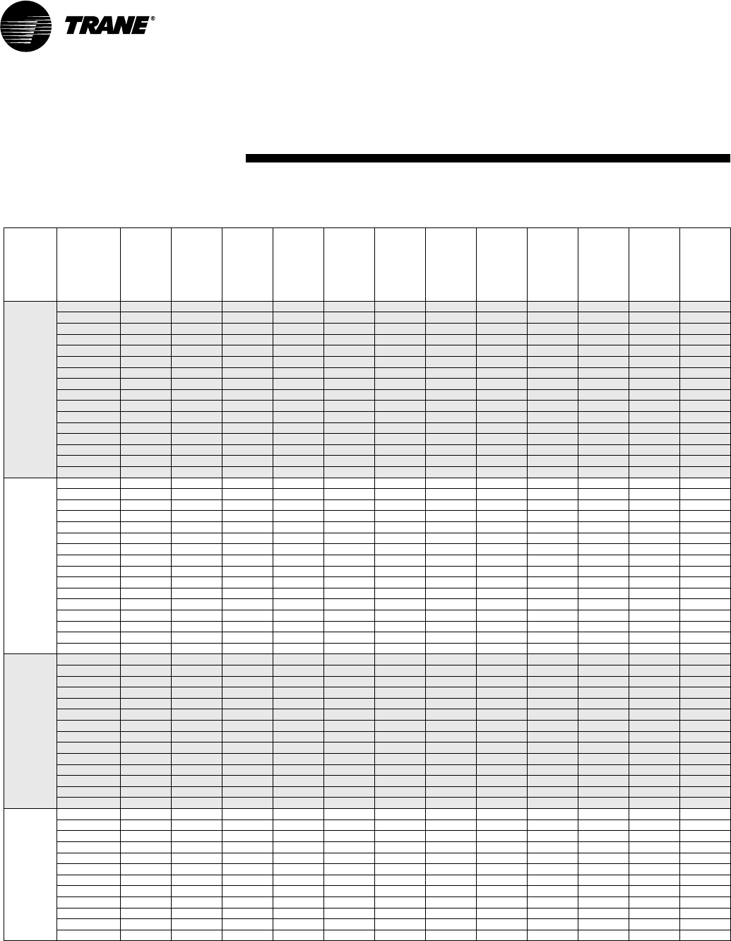
64 WSHP-PRC001-EN
Performance Data
Electrical
E2-Electrical performance (continued)
Model No. Volts Total
FLA
Comp
RLA
(ea)
Comp
LRA
(ea)
No. of
Compres.
Cmp
MCC
Blower
Motor
FLA
Blower
Motor
HP
Fan
Motor
Num
Minimum
Circuit
Ampacity
Maximum
Overcur-
rent
Protec-
tive
Device
Electric
Heat
kW
Electric
Heat
Amps
024 208/60/1 12.7 10.90 56.0 115.3 2.10 1/3 115.7 25 0 0
208/60/1 17.5 10.9 56.0 115.3 2.10 1/3 122.3 25 3.26 15.7
230/60/1 12.7 10.90 56.0 115.3 2.10 1/3 115.7 25 0 0
230/60/1 19.2 10.9 56.0 115.3 2.10 1/3 124.0 25 4.00 17.4
220-240/50/1 12.4 10.90 58.0 115.3 1.53 1/3 115.2 25 0 0
220-240/50/1 24.03 10.9 58.0 115.3 1.53 1/3 130.0 35 5.40 22.5
265/60/1 11.4 9.90 55.0 113.8 1.53 1/3 113.9 20 0 0
265/60/1 21.53 9.9 55.0 113.8 1.53 1/3 126.9 30 5.30 20.0
208/60/3 9.3 7.50 51.0 110.5 1.80 1/3 111.2 15 0 0
208/60/3 10.8 7.5 51.0 110.5 1.80 1/3 113.5 15 3.26 9.0
230/60/3 9.3 7.50 51.0 110.5 1.80 1/3 111.2 15 0 0
230/60/3 11.8 7.5 51.0 110.5 1.80 1/3 114.8 15 4.00 10.0
380-415/50/3 5.0 4.00 28.0 15.6 0.95 1/3 16.0 15 0 0
380-415/50/3 8.45 4.0 28.0 15.6 0.95 1/3 110.6 15 5.40 7.5
460/60/3 4.9 3.90 25.0 15.4 0.95 1/3 15.8 15 0 0
460/60/3 7.65 3.9 25.0 15.4 0.95 1/3 19.6 15 5.30 6.7
030 208/60/1 14.2 12.40 61.0 1 17.4 2.10 1/3 1 17.6 30 0 0
208/60/1 21.5 12.4 61.0 1 17.4 2.10 1/3 1 27.3 30 4.10 19.7
230/60/1 14.2 12.40 61.0 1 17.4 2.10 1/3 1 17.6 30 0 0
230/60/1 23.5 12.4 61.0 1 17.4 2.10 1/3 1 29.8 30 5.00 21.7
220-240/50/1 16.4 13.60 64.0 1 19.1 2.77 1/2 1 19.8 30 0 0
220-240/50/1 29.97 13.6 64.0 1 19.1 2.77 1/2 1 37.5 40 6.52 27.2
265/60/1 12.4 10.90 58.0 1 15.3 1.53 1/3 1 15.2 25 0 0
265/60/1 26.43 10.9 58.0 1 15.3 1.53 1/3 1 33.0 35 6.60 24.9
208/60/3 9.5 7.70 55.0 1 10.8 1.80 1/3 1 11.4 15 0 0
208/60/3 13.2 7.7 55.0 1 10.8 1.80 1/3 1 16.5 20 4.10 11.4
230/60/3 9.5 7.70 55.0 1 10.8 1.80 1/3 1 11.4 15 0 0
230/60/3 14.4 7.7 55.0 1 10.8 1.80 1/3 1 18.0 20 5.00 12.6
380-415/50/3 6.6 4.90 33.0 1 6.9 1.70 1/2 1 7.8 15 0 0
380-415/50/3 10.8 4.9 33.0 1 6.9 1.70 1/2 1 13.5 15 6.52 9.1
460/60/3 5.0 4.00 28.0 1 5.6 0.95 1/3 1 6.0 15 0 0
460/60/3 9.25 4.0 28.0 1 5.6 0.95 1/3 1 11.6 15 6.60 8.3
036 208/60/1 19.3 16.00 82.0 122.4 3.60 1/2 123.6 35 0 0
208/60/1 26.87 16.0 82.0 122.4 3.60 1/2 134.0 35 4.90 23.6
230/60/1 19.3 16.00 82.0 122.4 3.60 1/2 123.6 35 0 0
230/60/1 29.37 16.0 82.0 122.4 3.60 1/2 137.1 40 6.00 26.1
265/60/1 16.4 13.60 64.0 119.1 2.77 1/2 119.8 30 0 0
265/60/1 32.77 13.6 64.0 119.1 2.77 1/2 141.0 45 7.95 30.0
208/60/3 13.7 10.40 65.5 114.6 3.60 1/2 116.6 25 0 0
208/60/3 16.87 10.4 65.5 114.6 3.60 1/2 121.5 25 4.90 13.6
230/60/3 13.7 10.40 65.5 114.6 3.60 1/2 116.6 25 0 0
230/60/3 18.37 10.4 65.5 114.6 3.60 1/2 123.4 25 6.00 15.1
380-415/50/3 6.5 4.80 40.0 16.7 1.70 1/2 17.7 15 0 0
380-415/50/3 11.6 4.8 40.0 16.7 1.70 1/2 114.5 15 7.15 9.9
460/60/3 6.6 4.90 33.0 16.9 1.70 1/2 17.8 15 0 0
460/60/3 11.7 4.9 33.0 16.9 1.70 1/2 114.6 15 7.95 10.0
GEV 040 208/60/1 19.4 16.1 82.0 1 22.5 3.60 1/2 1 23.7 35 0 0
208/60/1 29.27 16.1 82.0 1 22.5 3.60 1/2 1 37.0 40 5.40 26.0
230/60/1 19.4 16.1 82.0 1 22.5 3.60 1/2 1 23.7 35 0 0
230/60/1 31.97 16.1 82.0 1 22.5 3.60 1/2 1 40.4 45 6.60 28.7
265/60/1 17.8 15.0 83.0 1 21.0 2.77 1/2 1 21.5 35 0 0
265/60/1 35.97 15.0 83.0 1 0.0 2.77 1/2 1 45.0 45 8.80 33.2
208/60/3 13.3 10.0 70.0 1 14.0 3.60 1/2 1 16.1 25 0 0
208/60/3 18.27 10.0 70.0 1 14.0 3.60 1/2 1 23.3 25 5.40 15.0
230/60/3 13.3 10.0 70.0 1 14.0 3.60 1/2 1 16.1 25 0 0
230/60/3 19.87 10.0 70.0 1 14.0 3.60 1/2 1 25.3 30 6.60 16.6
460/60/3 6.8 5.1 33.0 1 7.1 1.70 1/2 1 8.1 15 0 0
460/60/3 12.7 5.1 33.0 1 7.1 1.70 1/2 1 15.9 20 8.80 11.0
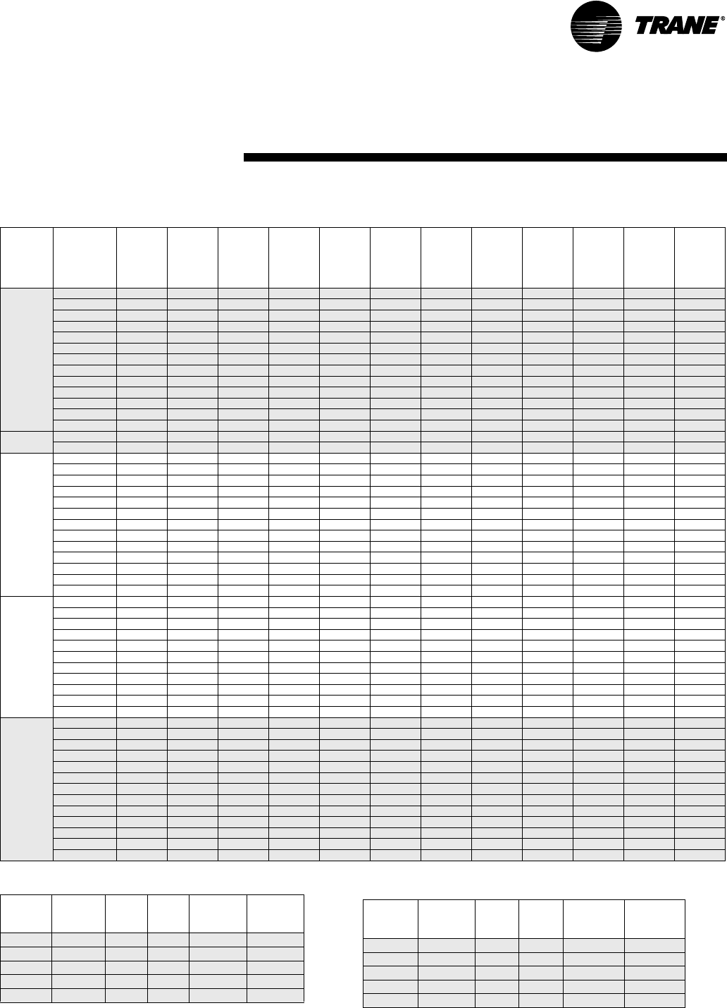
WSHP-PRC001-EN 65
Performance Data
Electrical
E4-Electrical minimum and maximum
E3-Electrical performance (continued)
Model No. Volts Total
FLA
Comp
RLA
(ea)
Comp
LRA
(ea)
No. of
Compres.
Cmp
MCC
Blower
Motor
FLA
Blower
Motor
HP
Fan
Motor
Num
Minimum
Circuit
Ampacity
Maximum
Overcur-
rent
Protective
Device
Electric
Heat
kW
Electric
Heat
Amps
042 - Hi
Static
208/60/1 21.3 18.00 96.0 125.2 3.60 1/2 126.1 40 0 0
208/60/1 30.67 18.0 96.0 125.2 3.60 1/2 138.8 40 5.70 27.4
230/60/1 21.3 18.00 96.0 125.2 3.60 1/2 126.1 40 0 0
230/60/1 33.67 18.0 96.0 125.2 3.60 1/2 142.5 45 7.00 30.4
208/60/3 14.7 11.40 75.0 116.0 3.60 1/2 117.9 25 0 0
208/60/3 19.07 11.4 75.0 116.0 3.60 1/2 124.3 25 5.70 15.8
230/60/3 14.7 11.40 75.0 116.0 3.60 1/2 117.9 25 0 0
230/60/3 20.87 11.4 75.0 116.0 3.60 1/2 126.5 30 7.00 17.6
380-415/50/3 9.1 6.40 42.0 18.9 2.70 1 1 10.7 15 0 0
380-415/50/3 14.7 6.4 42.0 18.9 2.70 1 1 18.4 20 8.60 12.0
460/60/3 6.5 4.80 40.0 16.7 1.70 1/2 17.7 15 0 0
460/60/3 13.4 4.8 40.0 16.7 1.70 1/2 116.8 20 9.30 11.7
575/60/3 5.4 4.10 31.0 15.7 1.31 1/2 16.4 15 0 0
042 - Std
Static 380-415/50/3 7.8 6.4 42.0 18.9 1.40 1/2 19.4 15 0 0
380-415/50/3 13.4 6.4 42.0 18.9 1.40 1/2 116.8 20 8.60 12.0
048 - Hi
Static
208/60/1 25.8 20.40 102.0 1 28.5 5.40 1 1 30.9 50 0 0
208/60/1 36.7 20.4 102.0 1 28.5 5.40 1 1 45.9 50 6.50 31.3
230/60/1 25.8 20.40 102.0 1 28.5 5.40 1 1 30.9 50 0 0
230/60/1 40.2 20.4 102.0 1 28.5 5.40 1 1 50.3 60 8.00 34.8
208/60/3 19.4 14.00 91.0 1 19.7 5.40 1 1 22.9 35 0 0
208/60/3 23.4 14.0 91.0 1 19.7 5.40 1 1 29.3 35 6.50 18.0
230/60/3 19.4 14.00 91.0 1 19.7 5.40 1 1 22.9 35 0 0
230/60/3 25.5 14.0 91.0 1 19.7 5.40 1 1 31.9 35 8.00 20.1
380-415/50/3 10.2 7.50 49.5 1 10.5 2.70 1 1 12.1 15 0 0
380-415/50/3 14.7 7.5 49.5 1 10.5 2.70 1 1 18.4 20 8.60 12.0
460/60/3 9.1 6.40 42.0 1 8.9 2.70 1 1 10.7 15 0 0
460/60/3 16.0 6.4 42.0 1 8.9 2.70 1 1 20.0 25 10.60 13.3
575/60/3 7.4 5.20 39.0 1 7.3 2.20 1 1 8.7 15 0 0
048 - Std
Static
208/60/1 23.2 20.4 102.0 1 28.5 2.80 1/2 1 28.3 50 0 0
208/60/1 34.1 20.4 102.0 1 28.5 2.80 1/2 1 42.6 50 6.50 31.3
230/60/1 23.2 20.4 102.0 1 28.5 2.80 1/2 1 28.3 50 0 0
230/60/1 37.6 20.4 102.0 1 28.5 2.80 1/2 1 47.0 50 8.00 34.8
208/60/3 16.8 14.0 91.0 1 19.7 2.80 1/2 1 20.3 35 0 0
208/60/3 20.8 14.0 91.0 1 19.7 2.80 1/2 1 26.0 35 6.50 18.0
230/60/3 16.8 14.0 91.0 1 19.7 2.80 1/2 1 20.3 35 0 0
230/60/3 22.9 14.0 91.0 1 19.7 2.80 1/2 1 28.6 35 8.00 20.1
460/60/3 7.8 6.4 42.0 1 8.9 1.40 1/2 1 9.4 15 0 0
460/60/3 14.7 6.4 42.0 1 8.9 1.40 1/2 1 18.4 25 10.60 13.3
575/60/3 6.3 5.2 39.0 1 7.3 1.10 1/2 1 7.6 15 0 0
060 208/60/1 33.4 28.00 169.0 139.0 5.40 1 1 40.4 60 0 0
208/60/1 36.7 28.0 169.0 139.0 5.4 1 1 45.9 60 6.50 31.3
230/60/1 33.4 28.00 169.0 135.0 5.40 1 1 40.4 60 0 0
230/60/1 40.2 28.0 169.0 139.0 5.4 1 1 50.3 60 8.00 34.8
208/60/3 25.4 20.00 123.0 128.0 5.40 1 1 30.4 50 0 0
208/60/3 25.4 20.0 123.0 127.0 5.4 1 1 30.4 50 6.50 18.0
230/60/3 25.4 20.00 123.0 128.0 5.40 1 1 30.4 50 0 0
230/60/3 25.5 20.0 123.0 127.0 5.4 1 1 31.9 50 8.00 20.1
380-415/50/3 12.8 10.00 62.0 114.0 2.70 1 1 15.2 25 0 0
380-415/50/3 14.7 10.0 62.0 114.0 2.7 1 1 18.4 25 8.60 12.0
460/60/3 10.2 7.50 49.5 110.5 2.70 1 1 12.1 15 0 0
460/60/3 16.0 7.5 49.5 110.5 2.7 1 1 20.0 25 10.60 13.3
575/60/3 8.6 6.40 40.0 19.0 2.20 1 1 10.2 15 0 0
Digit 8 Rated
Voltage
HZ Ph Minimum
Utilization
Voltage
Maximum
Utilization
Voltage
0115 60 1104 126
1208 60 1197 229
2230 60 1207 253
3208 60 3187 229
4460 60 3414 506
E4-Electrical minimum and maximum (continued)
Digit 8 Rated
Voltage
HZ Ph Minimum
Utilization
Voltage
Maximum
Utilization
Voltage
5575 60 3518 633
6220-240 50 1198 264
7265 60 1239 292
8230 60 3207 253
9380-415 60 3342 456
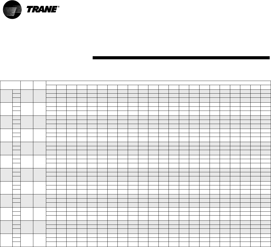
66 WSHP-PRC001-EN
Table F1: Fan performance for standard static motor includes wet coil and 1" filter
Model
Number
Max
CFM
Min
CFM
External Static Pressure (in. of wg)
0 .05.1.15.2.25.3.35.4.45.5.55.6.65.7.75.8.85.9.95 11.05
006 High 342
228
----------236 205 161 100 --------
Med ---------239 222 200 169 125 --------
Low -------235 222 208 191 169 138 ---------
009 High 342
228
----345330316302289275258236205---------
Med --341325309294280266253239222-----------
Low 342325310294278263249235222-------------
012 High 456
304
-----------462 424 347 211 -------
Med -----459 451 447 46 446 443 428 390 313 177 -------
Low - - 464 453 441 431 423 419 418 418 415 400 362 285 --------
015 High 550
368
550537526515503493485481480480477462424347--------
Med 51650349248146945945144746446443428390313--------
Low 488475464453441431423419418418415400362---------
018 High 684
456
- - 688 675 664 649 633 612 587 560 522 457 427 ---------
Med 657 652 644 633 621 605 587 568 543 512 475 429 ----------
Low 632 624 615 604 592 578 561 540 513 481 431 -----------
024 High 912
608
-----922903883860833802766723675623572------
Med 915901891879866851835819801779751715670621577-------
Low 827819806793780769756741723701674642605---------
030 High 1009
720
1009 988 971 955 939 922 903 883 860 833 802 766 723 675 --------
Med 915 901 891 879 866 851 835 819 801 779 751 715 ----------
Low 827 819 806 793 780 769 756 741 723 701 ------------
036 High 1368
912
-----1381136613511334 1315 1295 1272 1247 1219 1187 1152 1112 1068 1018 963 901 -
Med 1221 1218 1216 1211 1206 1199 1190 1181 1170 1159 1146 1132 1116 1096 1073 1044 1010 969 922 867 - -
Low 1099 1094 1090 1087 1083 1079 1075 1069 1062 1052 1040 1025 1007 985 958 927 890 - - - - -
GEVA
040
High 1440
960
1480 1460 1429 1391 1349 1304 1258 1213 1168 1124 1082 1039 997 953 --------
Med 1311 1294 1268 1237 1203 1168 1134 1101 1068 1035 1002 968 931 ---------
Low 1199 1191 1174 1151 1125 1098 1070 1042 1013 985 955 -----------
042 High 1436
1064
1436 1427 1417 1406 1394 1381 1366 1351 1334 1315 1295 1272 1247 1219 1187 1152 1112 1068 1018 - - -
Med 1221 1218 1216 1211 1206 1199 1190 1181 1170 1159 1146 1132 1116 1096 1073 1044 - - - - - -
Low 1099 1094 1090 1087 1083 1079 1075 1069 1062 -------------
048 High 1824
1216
1850 1786 1732 1686 1646 1608 1572 1536 1499 1459 1417 1371 1323 1272 1216 -------
Med 1783 1724 1675 1632 1595 1560 1525 1491 1455 1417 1376 1332 1285 1216 --- ----- -- -
Low 1687 1639 1598 1562 1530 1499 1467 1434 1399 1362 1321 1278 1216 ---------
060 High 2266
1520
2266 2246 2221 2194 2165 2133 2099 2063 2024 1984 1943 1899 1854 1808 1761 1712 1664 1615 1566 1517 - -
Med 2056 2036 2011 1984 1955 1923 1889 1853 1814 1774 1733 1689 1644 1598 1551 1502 - - - - - -
Low 1883 1863 1838 1811 1782 1750 1716 1680 1641 1601 1560 1516 - - --------
Performance Data
Fan Performance
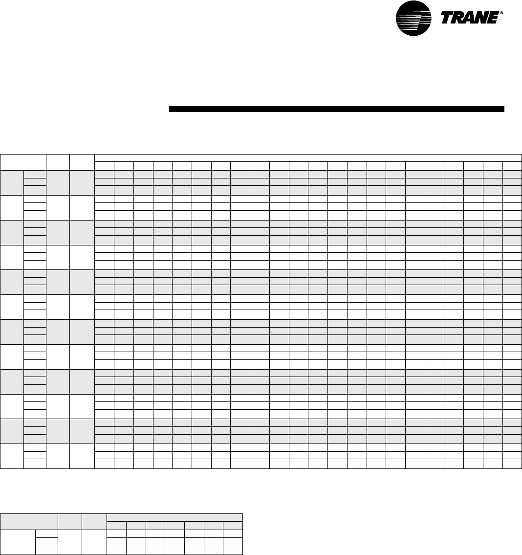
WSHP-PRC001-EN 67
Table F-2: Fan performance (high static option) includes wet coil and 1" filter
Model
Number
Max
CFM
Min
CFM
External Static Pressure (in. of wg)
0 .05 .1 .15 .2 .25 .3 .35 .4 .45 .5 .55 .6 .65 .7 .75 .8 .85 .9 .95 1 1.05
006 High -
-
------------248 204 143 -------
Med -----------236 205 161 100 -------
Low ---------239 222 200 169 125 --------
009 High 342
228
-------345332318301279248204--------
Med ----345330316302289275258236205---------
Low --341325309294280266253239222-----------
012 High 456
304
-----------488 450 373 237 -------
Med -----------462 424 347 211 -------
Low -----459 451 447 446 446 443 428 390 313 177 -------
015 High 550
368
--552541529519511507506506503488450373237-------
Med 550537526515503493485481480480477462424347--------
Low 516503492481469459451447461446443428390313--------
018 High 684
456
-----------725 676 623 566 503 431 - - - - -
Med ----------705 657 608 556 504 450 - - - - - -
Low ---------708 668 626 580 533 483 431 - - - - - -
024 High 912
608
--------935906875841802755695615504-----
Med -----922903883860833802766723675623572------
Low 915901891879866851835819801779751715670621577-------
030 High 1009
720
-1097 1074 1053 1033 1011 988 962 935 906 875 841 802 755 695 -------
Med 1009 988 971 955 939 922 903 883 860 833 802 766 723 675 --------
Low 915 901 891 879 866 851 835 819 801 779 751 715 ----------
036 High 1368
912
-----------139613641329129112491203115411001042979910
Med -----1381 1366 1351 1334 1315 1295 1272 1247 1219 1187 1152 1112 1068 1018 963 901 -
Low 1221 1218 1216 1211 1206 1199 1190 1181 1170 1159 1146 1132 1116 1096 1073 1044 1010 969 922 867 - -
GEVA
040
High 1440
960
---1480 1436 1389 1340 1291 1242 1194 1146 1098 1051 1004 956 -------
Med -1460 1429 1391 1349 1304 1258 1213 1168 1124 1082 1039 997 953 --- - - - - -
Low 1311 1294 1268 1237 1203 1168 1134 1101 1068 1035 1002 968 931 - - -- - - - - -
042 High 1596
1064
- 1605 1585 1566 1548 1531 1512 1493 1472 1449 1424 1396 1364 1329 1291 1249 1203 1154 1100 1042 - -
Med 1436 1427 1417 1406 1394 1381 1366 1351 1334 1315 1295 1272 1247 1219 1187 1152 1112 1068 1018 - - -
Low 1221121812161211120611991190118111701159114611321116109610731044------
048 High 1824
1216
--------------1831 1782 1734 1684 1636 1587 1540 1493
Med ------------1854 1808 1761 1712 1664 1615 1566 1517 1470 1423
Low -------1853 1814 1774 1733 1689 1644 1598 1551 1502 1454 1405 1356 1307 1260 1213
060 High 2266
1520
- - 2291 2264 2235 2203 2169 2133 2094 2054 2013 1969 1924 1878 1831 1782 1734 1684 1636 1587 1540 1493
Med 2266 2246 2221 2194 2165 2133 2099 2063 2024 1984 1943 1899 1854 1808 1761 1712 1664 1615 1566 1517 - -
Low 2056 2036 2011 1984 1955 1923 1889 1853 1814 1774 1733 1689 1644 1598 1551 1502 ------
Table F-3: Fan performance (high static option)
includes wet coil and 1" filter
Model Number Max
CFM
Min
CFM
External Static Pressure (in. of wg)
1.1 1.15 1.2 1.25 1.3 1.35 1.4
GEHA
048
High 1824
1216
1448 1404 1362 1321 1281 1242 1201
Med 1378 1334 1292 1251 1211 - -
High -------
Performance Data
Fan Performance
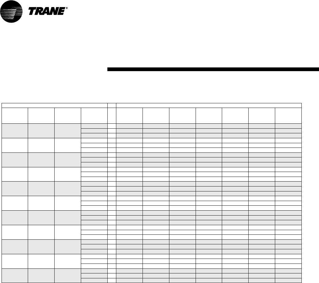
68 WSHP-PRC001-EN
Performance data is tabulated for cooling at 80 F DB/67 F WB entering air and 45 F entering fluid at ARI 410 rated SCFM.
Table W1: Waterside Economizer Performance Data (1/2 through 5 Tons)
Input Data Output Data
Tonnage
of Heat
Pump
Model
GEH
SCFM GPM Total
Capacity
(MBH)
Sensible
Capacity
(MBH)
LVG. Air
DB
(Deg F)
LVG. Air
WB
(Deg F)
Standard
APD
(IN WG)
LVG.Fluid
Temp .
Degree F
Fluid PD
(FT H2O)
0.50 006 190 1.2 5.83 4.28 59.4 57.3 0.03 54.7 0.23
1.5 6.3 4.6 58.5 56.5 0.03 53.4 0.34
1.7 6.65 4.61 57.8 55.8 0.03 52.8 0.42
0.75 009 285 1.7 7.86 5.91 61.1 58.4 0.07 54.2 0.42
2.1 8.49 6.14 60.3 57.7 0.07 53.1 0.60
2.3 8.76 6.25 60.0 57.3 0.07 52.6 0.71
1.00 012 380 2.2 9.75 7.41 62.2 59.1 0.11 53.8 0.65
2.8 10.6 7.72 61.4 58.3 0.11 52.6 0.99
3.1 11.03 7.91 61.0 57.9 0.11 52.1 1.18
1.25 015 460 2.8 11.44 8.68 62.7 59.3 0.15 53.1 0.99
3.5 12.33 9.03 62.1 58.7 0.15 52.0 1.46
3.8 12.69 9.19 61.7 58.4 0.15 51.7 1.69
1.50 018 570 3.3 16.27 11.71 61.2 58.1 0.12 54.8 1.36
4.2 17.61 12.25 60.4 57.3 0.12 53.4 2.08
4.6 18.05 12.42 60.1 57.0 0.12 52.8 2.45
2.00 024 760 4.4 20.25 14.65 62.4 58.7 0.19 54.2 2.26
5.5 21.58 15.21 61.7 0.2 0.19 52.8 3.4
6.1 22.19 15.43 61.4 57.9 0.19 52.3 4.03
2.50 030 900 5.5 23.27 16.81 62.9 59.0 0.25 53.4 3.4
6.9 24.71 17.38 62.3 58.5 0.25 52.1 5.01
7.6 25.28 17.64 62.1 58.3 0.25 51.6 5.95
3.00 036 1140 6.6 29.28 21.57 62.7 59.1 0.19 53.8 2.39
8.3 31.47 22.41 62.0 58.4 0.19 52.6 5.25
9.1 32.2 22.2 61.8 58.2 0.19 52.1 6.19
3.50 042 1330 7.8 32.88 24.88 63.4 59.4 0.25 53.4 4.70
9.7 34.81 25.05 62.8 58.9 0.25 52.2 6.92
10.7 35.67 25.37 62.6 58.7 0.25 51.6 8.24
4.00 048 1520 8.8 39.77 29.11 62.5 58.9 0.17 54.0 1.24
11 42.44 30.25 61.8 58.3 0.17 52.7 1.86
12.1 43.65 30.69 61.5 58.0 0.17 52.2 2.21
5.00 060 1900 11.6 47.59 34.73 63.3 59.3 0.24 53.2 2.04
14.5 50.66 35.94 62.7 58.7 0.24 52.0 3.05
16 51.87 36.39 62.5 58.5 0.24 51.5 3.65
Performance Data
Waterside Economizer
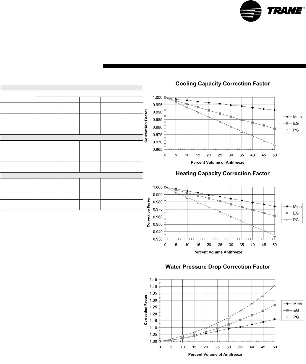
WSHP-PRC001-EN 69
Performance Data
Antifreeze Correction Factors
Table A1: Correction Factors for Antifreeze Solutions
Methanol
Item
Concentration by Volume
10% 20% 30% 40% 50%
Cool
Capacity
.9980 .9965 .9949 .9932 .9915
Heat
Capacity
.9950 .9898 .9846 .9794 .9742
Pressure
Drop
1.023 1.057 1.091 1.122 1.160
Ethylene Glycol
Cool
Capacity
.9955 .9912 .9870 .9830 .9790
Heat
Capacity
.9925 .9848 .9770 .9690 .9610
Pressure
Drop
1.024 1.068 1.124 1.188 1.263
Propylene Glycol
Cool
Capacity
.9934 .9869 .9804 .9739 .9681
Heat
Capacity
.9863 .9732 .9603 .9477 .9350
Pressure
Drop
1.040 1.098 1.174 1.273 1.405
Example 1 (Ethylene Glycol):
The antifreeze solution is 20% by volume of Ethylene Gly-
col. Determine the corrected cooling capacity and water-
side pressure drop for a GEHB 018 when the EWT is 86 F
and the GPM is 4.2.
From the catalog data, the cooling capacity at these condi-
tions with 100% water is 18.6 MBTUH, and the waterside
pressure drop is 6.0 feet of head. At 20% Ethylene Glycol,
the correction factor for cool capacity is 0.9912 and the
pressure drop is 1.068.
The corrected cooling capacity (MBTUH) = 18.6 * 0.9912 =
18.4. The corrected water side pressure drop (Ft. head) =
6.9 * 1.068 = 7.4.
Example 2 (Propylene Glycol):
The antifreeze solution is 30% by volume of Propylene
Glycol. Determine the corrected heating capacity and
waterside pressure drop for a GEHB 042 when the EWT is
45 F and the GPM is 9.7.
From the catalog data, the heating capacity at these condi-
tions with 100% water is 36.7 MBTUH, and the waterside
pressure drop is 16.1 feet of head. At 30% Propylene Glycol,
the correction factor for heat capacity is 0.9603 and the pres-
sure drop is 1.174.
The corrected cooling capacity (MBTUH) = 36.7 * 0.9603 =
35.2. The corrected water side pressure drop (Ft. head) =
16.1 * 1.174 = 18.9.
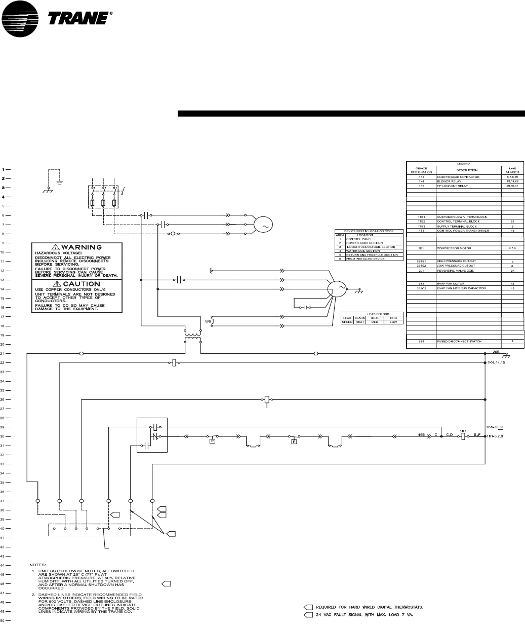
70 WSHP-PRC001-EN
3B2C2
M
1K4
3B2
BRN
5B
GRN
GROUND
EQUIPMENT
1A
CONTACTS BY LINE NUMBER.
SCHEMATIC DESIGNATE THE LOCATION OF THE
NUMBERS ALONG THE RIGHT SIDE OF THE
LOCAL REQUIREMENTS.
THE NATIONAL ELECTRIC CODE (NEC), STATE AND
ALL FIELD WIRING MUST BE IN ACCORDANCE WITH
4.
3.
A
B
A
1TB2-3 & 4
26
26G
C2 C1
5
45D
1K5
C2
6
46C
W225A
24A
SINGLE
STAGE
ROOM
T'STAT
A
1TB1-3
23
22A
B,C,E,G
1TB2-1 & 2
21
BA
BRGOWY
UNITS WITH
REVERSING VALVE
ADD JUMPER
BETWEEN
Y & W
A,B
AA
AGA
1TB1-1
21
1TB1-2
22
1TB1-4
24
1TB1-5
25
1TB1-6
26
5
5
BETWEEN TERMINALS 1TB1-4 AND 1TB1-6 TO HAVE
FIELD INSTALLED SOLENOID VALVE CAN BE WIRED
IT ENERGIZE WITH THE COMPRESSOR RUN SIGNAL.
5
6S4
1K1
1K1
L3
4A
5A
6A
1
460/60/3
L2L1
23A
2L1
F
2B1S22B1S1
BRN
C
P2-4
J2-4 J2-2
P2-2J2-1 P2-1
1K4
2A,J
P1-3 J1-3
46B 47B 48B
P2-5
J2-5
49B J2-3
P2-3
44B
P2-6 J2-6
W3
3
1
6B
2B1
M
P4-1 J4-1
4B
P4-2 J4-2
P4-3 J4-3
3
2J YEL
11A
9A
P1-5 J1-5
ORG
BLU
P1-6 J1-6
8A
7A PUR
BLK
P1-2 J1-2
P1-1 J1-1
8A LEAD WHEN BLACK WIRE OF
NOTE: CONNECT 7A LEAD WITH
MOTOR IS NOT BEING USED
C
12
12
13
13
1T1
24V
T1
T2
T3
COM
460/60/3
1TB3
6
Control Wiring
Basic 24V - 1 PH
208V-60HZ-1PH
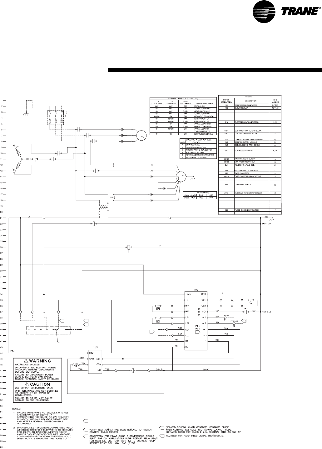
WSHP-PRC001-EN 71
3B2C2
M
1K4
3B2
BRN
5B
GRN
GROUND
EQUIPMENT
1A
CONTACTS BY LINE NUMBER.
SCHEMATIC DESIGNATE THE LOCATION OF THE
NUMBERS ALONG THE RIGHT SIDE OF THE
LOCAL REQUIREMENTS.
THE NATIONAL ELECTRIC CODE (NEC), STATE AND
ALL FIELD WIRING MUST BE IN ACCORDANCE WITH
4.
3.
A
B
A
1TB2-3 & 4
26
LED3
LED2
LED1
6
7
1TB1-10
54
1TB1-9
53
44A
45A
3S3
C
SINGLE
STAGE
ROOM
T'STAT
21C
G
B,C,E,G,M
BRGOWY
1TB1-2
22
1TB1-1
21
11
A,B
1TB1-6
26
1TB1-4
24
55
AAG
6
C
71B
71A,B
,K,R
1
460/60/3
2B1S1
47A
46A
2B1S2
49A
48A
70A
BRN
B
1TB2-1 & 2
21
A,C
1K4
22A
1K10
1K10
7
3HR
BETWEEN TERMINALS 1TB1-4 AND 1TB1-6 TO HAVE
FIELD INSTALLED SOLENOID VALVE CAN BE WIRED
IT ENERGIZE WITH THE COMPRESSOR RUN SIGNAL.
5
C
C
34A
35A
35C
2A,J
1C
,B C
2L1
23A
1TB1-3
23
A
UNITS WITH
REVERSING VALVE
ADD JUMPER
BETWEEN
Y & W
P1-3 J1-3
J2-6 P2-6
J2-3 P2-3
44B
45B
P2-1 J2-1
P2-4 J2-4
46B
47B
P2-2 J2-2
P2-5 J2-5
48B
49B
3
1
6B
2B1
M
P4-1 J4-1
4B
P4-2 J4-2
P4-3 J4-3
4RT2
2J YEL
11A
9A
P1-5 J1-5
ORG
BLU
P1-6 J1-6
8A
7A PUR
BLK
P1-2 J1-2
P1-1 J1-1
8A LEAD WHEN BLACK WIRE OF
NOTE: CONNECT 7A LEAD WITH
MOTOR IS NOT BEING USED
C
12
1T1
24V
12
COM
460/60/3
37A
37B
1TB1-13
72
1TB1-18
26
1K10
26U72C
,C
44C
45E
3
L1
6S4
1K1
1K1
L3L2
6A
5A
4A
T3
T2
T1
1K1
35C
Control Wiring
Deluxe 24V - 3 PH
208V-60HZ-3PH
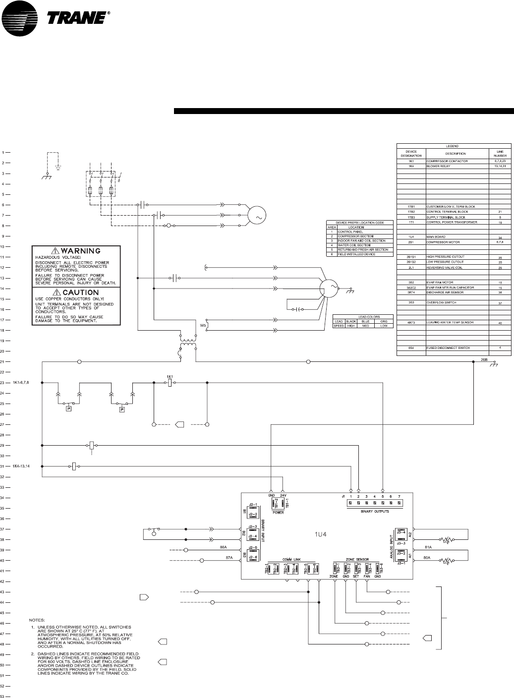
72 WSHP-PRC001-EN
3B2C2
M
1K4
3B2
BRN
5B
GRN
GROUND
EQUIPMENT
1A
CONTACTS BY LINE NUMBER.
SCHEMATIC DESIGNATE THE LOCATION OF THE
NUMBERS ALONG THE RIGHT SIDE OF THE
LOCAL REQUIREMENTS.
THE NATIONAL ELECTRIC CODE (NEC), STATE AND
ALL FIELD WIRING MUST BE IN ACCORDANCE WITH
4.
3.
A
B
A
1TB2-3 & 4
26
A,B
6S4
1K1
1K1
L3
4A
5A
6A
1
460/60/3
L2L1
1TB2-1 & 2
21
1TB1-10
87
1TB1-7
1TB1-9
86
1TB1-5
78
1TB1-6
79
1TB1-8
1TB1-1
67
1TB1-3
69
1TB1-2
68
1TB1-4
75
3RT4
4RT3
1K4
ZONE TEMP
COMMON
SET POINT
FAN MODE
CONDENSATE
OVERFLOW
OCCUPANCY
OPTIONAL
6COMMUNICATION WIRE MUST BE TRANE PART NO.
400-20-28, OR WINDY CITY OR CONNECT AIR
"LEVEL 4" CABLE. MAXIMUM OF 4500 FOOT
AGGREGATE RUN.
CAUTION! DO NOT RUN POWER IN THE SAME
CONDUIT OR WIRE BUNDLE WITH COMMUNICATION
LINK. FOR ADDITIONAL INFROMATION REFER TO EMTX-EB-68.
BRN
2L1
2B1S1 2B1S2
1TB1-12
20
1TB1-11
49
5
FIELD INSTALLED SOLENOID VALVE CAN BE WIRED
BETWEEN TERMINALS 1TB1-11 AND 1TB1-12 TO
HAVE IT ENERGIZE WITH THE COMPRESSOR RUN SIGNAL.
5
CONNECTIONS
B
K,L
21K
L,M
P 64A
M W2 49C 20A,B B
67A
68A
69A
75A
26U
79A,W5
78A,W4
B,U
,P
2A,J
A
P1-3 J1-3
45A
44A
3S3 44B
45B
J2-1
P2-1
46B
J2-4
P2-4
47B
J2-2
P2-2
48B 49B
J2-5
P2-5
3
1
6B
2B1
M
P4-1 J4-1
4B
P4-2 J4-2
P4-3 J4-3
3
ZONE
SENSOR
COMM LINK
79A
78A
D
C,D
7VA MAX RATING FOR SOLENOID.
W4
W5
21K
26U
P2-3 J2-3
P2-6 J2-6
83A
82A
DISCHARGE AIR
SENSOR
SENSOR
LEAVING WATER
20B64A
63A
6
63A
2J YEL
11A
9A
P1-5 J1-5
ORG
BLU
P1-6 J1-6
8A
7A PUR
BLK
P1-2 J1-2
P1-1 J1-1
8A LEAD WHEN BLACK WIRE OF
NOTE: CONNECT 7A LEAD WITH
MOTOR IS NOT BEING USED
1T1
24V
T1
T2
T3
6
COM
P14-1 P14-2 P14-5
460/60/3
44C
45E
1TB3
6
Control Wiring
Tracer ZN510-1PH
208V-60HZ-1PH
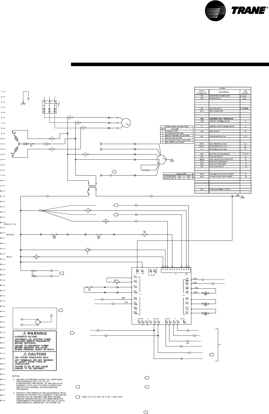
WSHP-PRC001-EN 73
3B2C2
M
1K4
3B2
BRN
5B
GRN
GROUND
EQUIPMENT
1A
CONTACTS BY LINE NUMBER.
SCHEMATIC DESIGNATE THE LOCATION OF THE
NUMBERS ALONG THE RIGHT SIDE OF THE
LOCAL REQUIREMENTS.
THE NATIONAL ELECTRIC CODE (NEC), STATE AND
ALL FIELD WIRING MUST BE IN ACCORDANCE WITH
4.
3.
A
B
A
1TB2-3 & 4
26
A,B
1
460/60/3
BRN
2A,J
P1-3 J1-3
3
1
6B
2B1
M
P4-1 J4-1
4B
P4-2 J4-2
P4-3 J4-3
2J YEL
NOTE: CONNECT 7A LEAD WITH
8A LEAD WHEN BLACK WIRE OF
MOTOR IS NOT BEING USED.
9A
J1-5
ORG
BLK
P1-2 J1-2
BLU
P1-6 J1-6
8A
7A PUR
P1-1 J1-1
11A
1T1
24V
COM
460/60/3
3
L1
6S4
1K1
1K1
L3L2
6A
5A
4A
T3
T2
T1
1K1
BETWEEN TERMINALS 1TB1-16 AND 1TB1-18.
FIELD INSTALLED SOLENOID VALVE CAN BE WIRED
LINK. FOR ADDITIONAL INFROMATION REFER TO EMTX-EB-68.
CONDUIT OR WIRE BUNDLE WITH COMMUNICATION
CAUTION! DO NOT RUN POWER IN THE SAME
"LEVEL 4" CABLE. MAXIMUM OF 4500 FOOT
400-20-28, OR WINDY CITY OR CONNECT AIR
93B
2L1
H20 ECON
1TB1-15
1TB1-14
CLOSE
OPEN
H20
VLV
1K4
21K
L,M
INSET A
12VA MAX RATING FOR SOLENOID.
AGGREGATE RUN.
6
5
COMM LINK
CONNECTIONS
OCCUPANCY
6
OPTIONAL
7
1TB2-4
CMN
63A
OVERFLOW
CONDENSATE
1TB1-10
87
1TB1-8
1TB1-7 W4
W5
1TB1-9
86
TEMP SENSOR
EVAP LOW
3S3
45E
44C
P2-6 J2-6
P2-3 J2-3
45B
44B
34A
1K10
35C
100A
56
1K9
Y2
V
Z
21
4101A
3HR
37B
37A
35A
A
1K10
47B
P2-4
1TB1-14
2B1S1
P
1TB1-15
7
J2-4 J2-2
W2
SEE INSET A
21X
21W
B
ISO VLV
OA DMP
FIELD SUPPLIED
FIELD SUPPLIED
1K10
48B
P2-2
2B1S2
1K9
64A
P2-5
49B
J2-5
5
8
91A
1C
1K10
C
C
,C
3A
1TB2-1 & 2
21
46B
P2-1J2-1
M
Y, 1TB1-18
K,L,Z,P
FAN MODE
SET POINT
COMMON
4RT3
3RT4
4RT2
FIELD INSTALLED 2 POSITION ACTUATOR CAN BE WIRED
1TB1-6
79
BETWEEN TERMINALS 1TB1-17 AND 1TB1-18.
12VA MAX RATING FOR SOLENOID.
12VA MAX RATING FOR SOLENOID.
BETWEEN TERMINALS 1TB1-14 AND 1TB1-15.
FIELD INSTALLED SOLENOID VALVE CAN BE WIRED
8
7
1TB1-5
78
78A,W4
P14-2
1U8
78A 79A
21K
104A
45A
44A
105A
26U
P14-1
1
63A
82A
1TB1-1
67
75A
79A,W5
68A
67A
69A
1TB1-4
75 1TB1-3
69
1TB1-2
68
107A
106A
10
P14-5
P14-3
23 54
P14-9
7698
83A
P14-11
P14-12
1211
6
SENSOR
SENSOR
ZONE
SENSOR
ENTERING WATER
ZONE TEMP
LEAVING WATER
DISCHARGE AIR
SENSOR
SENSOR
HUMIDITY/CO2/UNIV
93A
49C
1TB1-17
90
1TB1-16
92
1TB1-13
93
26U
64A
20B
92A
91A
90A
B,U
26U
1TB1-11
112A 1TB1-12
113
W5
15
15
TIE BACK WHEN NOT IN USE
COMMUNICATION WIRE MUST BE TRANE PART NO.
P1-5
Dimensional Data
Tracer ZN524-3PH
460V-60HZ-3PH
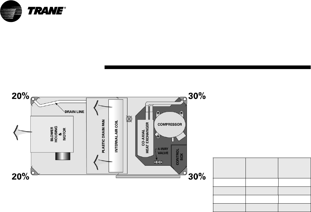
74 WSHP-PRC001-EN
Weight Distribution
Approximate weight distribution
for the GEH model is indicated in
Figure 39.
Tolerance on the weights deter-
mined are ±15 %.
Total weights for each unit are list-
ed below.
GEH Unit
Shipping
Weight
(lbs)
Running
Weight
(lbs)
006-015 188 158
018-030 278 248
036-042 318 288
048, 060 428 398
Dimensional Data
Weight Distribution
Figure 39: Approximate weight distribution
2
3
1
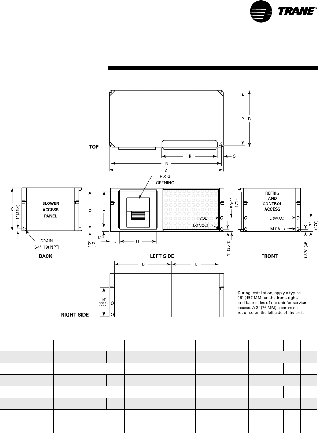
WSHP-PRC001-EN 75
Dimensional Data
Left Return/Left Supply
Unit A B C D E F G H J K L
NPTI
M
NPTI NPQRS
006,009 40"
(1016)
20"
(508)
15"
(381)
20"
(508)
15"
(381)
6 7/8"
(175)
8"
(203)
11 1/2"
(292)
4 1/4"
(108)
1 3/4"
(45)
1/2"
(12.7)
1/2"
(12.7)
38 3/4"
(984)
18 3/4"
(476)
13 5/8"
(346)
18 1/2"
(470)
3 1/4"
(83)
012, 015 40"
(1016)
20"
(508)
15"
(381)
20"
(508)
15"
(381)
6 7/8"
(175)
9 7/8"
(251)
11 1/2"
(292)
4 1/4"
(108)
2 3/4"
(70)
1/2"
(12.7)
1/2"
(12.7)
38 3/4"
(984)
18 3/4"
(476)
13 5/8"
(346)
18 1/2"
(470)
3 1/4"
(83)
018 46"
(1168)
23"
(584)
17"
(432)
23"
(584)
18"
(457)
8 1/4"
(210)
9 3/4"
(248)
13 1/2"
(343)
4 3/4"
(121)
2 1/4"
(57)
3/4"
(19)
3/4"
(19)
44 3/4"
(1137)
21 3/4"
(552)
15 5/8"
(397)
18 1/2"
(470)
4 1/4"
(108)
024, 030 46"
(1168)
23"
(584)
17"
(432)
23"
(584)
18"
(457)
8 1/4"
(210)
11 3/8"
(289)
13 1/2"
(343)
4 3/4"
(121)
2 1/4"
(57)
3/4"
(19)
3/4"
(19)
44 3/4"
(1137)
21 3/4"
(552)
15 5/8"
(397)
18 1/2"
(470)
4 1/4"
(108)
036, 042 50"
(1270)
25"
(635)
19"
(483)
25"
(635)
20"
(508)
10 1/2"
(267)
13 1/2"
(343)
16 3/8"
(416)
4"
(102)
1"
(25.4)
3/4"
(19)
3/4"
(19)
48 3/4"
(1238)
23 3/4"
(603)
17 5/8"
(448)
23 1/2"
(597)
3 1/4"
(83)
Std-048 58"
(1473)
33"
(838)
21"
(533)
23 1/2"
(597)
29 1/2"
(749)
13 1/8"
(333)
11 3/8"
(289)
18"
(457)
6 5/8"
(168)
1 1/2"
(38)
1"
(25.4)
1"
(25.4)
56 3/4"
(1441)
31 3/4"
(806)
19 5/8"
(498)
23 1/2"
(597)
5 1/2"
(140)
Hi-048,
060
58"
(1473)
33"
(838)
21"
(533)
23 1/2"
(597)
29 1/2"
(749)
13 7/8"
(352)
13 7/8"
(352)
18"
(457)
6 5/8"
(168)
1 1/2"
(38)
1"
(25.4)
1"
(25.4)
56 3/4"
(1441)
31 3/4"
(806)
19 5/8"
(498)
23 1/2"
(597)
5 1/2"
(140)
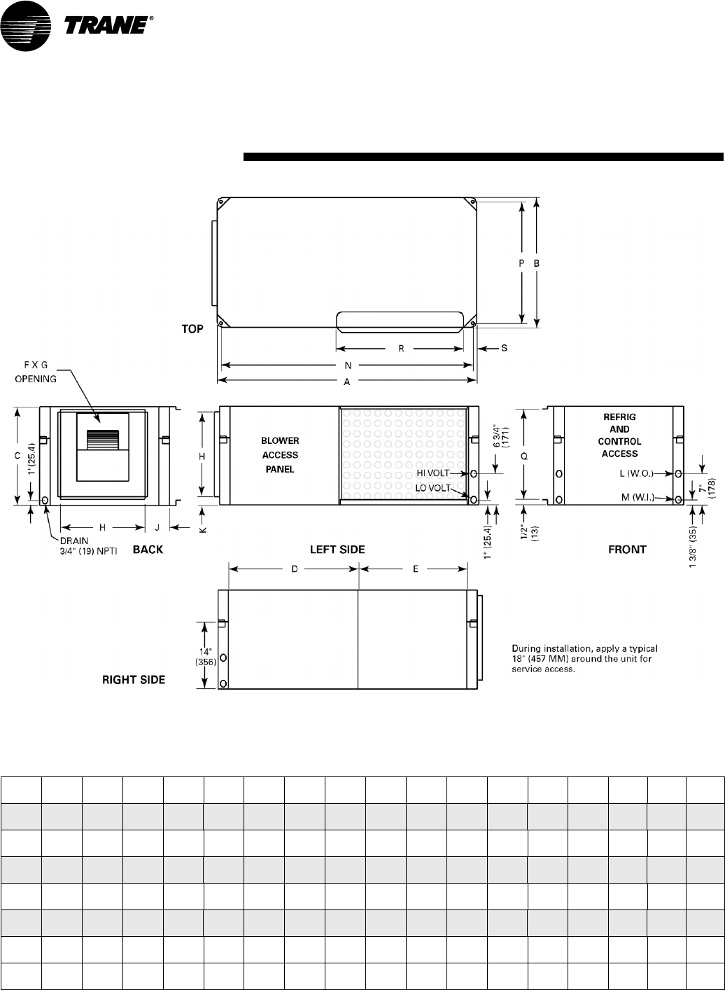
76 WSHP-PRC001-EN
Dimensional Data
Left Return/Back Supply
Unit A B C D E F G H J K L
NPTI
M
NPTI NPQRS
006,009 40"
(1016)
20"
(508)
15"
(381)
20"
(508)
15"
(381)
6 7/8"
(175)
8"
(203)
11 1/2"
(292)
4 1/4"
(108)
1 3/4"
(45)
1/2"
(12.7)
1/2"
(12.7)
38 3/4"
(984)
18 3/4"
(476)
13 5/8"
(346)
18 1/2"
(470)
3 1/4"
(83)
012, 015 40"
(1016)
20"
(508)
15"
(381)
20"
(508)
15"
(381)
6 7/8"
(175)
9 7/8"
(251)
11 1/2"
(292)
4 1/4"
(108)
2 3/4"
(70)
1/2"
(12.7)
1/2"
(12.7)
38 3/4"
(984)
18 3/4"
(476)
13 5/8"
(346)
18 1/2"
(470)
3 1/4"
(83)
018 46"
(1168)
23"
(584)
17"
(432)
23"
(584)
18"
(457)
8 1/4"
(210)
9 3/4"
(248)
13 1/2"
(343)
4 3/4"
(121)
2 1/4"
(57)
3/4"
(19)
3/4"
(19)
44 3/4"
(1137)
21 3/4"
(552)
15 5/8"
(397)
18 1/2"
(470)
4 1/4"
(108)
024, 030 46"
(1168)
23"
(584)
17"
(432)
23"
(584)
18"
(457)
8 1/4"
(210)
11 3/8"
(289)
13 1/2"
(343)
4 3/4"
(121)
2 1/4"
(57)
3/4"
(19)
3/4"
(19)
44 3/4"
(1137)
21 3/4"
(552)
15 5/8"
(397)
18 1/2"
(470)
4 1/4"
(108)
036, 042 50"
(1270)
25"
(635)
19"
(483)
25"
(635)
20"
(508)
10 1/2"
(267)
13 1/2"
(343)
16 3/8"
(416)
4"
(102)
1"
(25.4)
3/4"
(19)
3/4"
(19)
48 3/4"
(1238)
23 3/4"
(603)
17 5/8"
(448)
23 1/2"
(597)
3 1/4"
(83)
Std-048 58"
(1473)
33"
(838)
21"
(533)
23 1/2"
(597)
29 1/2"
(749)
13 1/8"
(333)
11 3/8"
(289)
18"
(457)
6 5/8"
(168)
1 1/2"
(38)
1"
(25.4)
1"
(25.4)
56 3/4"
(1441)
31 3/4"
(806)
19 5/8"
(498)
23 1/2"
(597)
5 1/2"
(140)
Hi-048,
060
58"
(1473)
33"
(838)
21"
(533)
23 1/2"
(597)
29 1/2"
(749)
13 7/8"
(352)
13 7/8"
(352)
18"
(457)
6 5/8"
(168)
1 1/2"
(38)
1"
(25.4)
1"
(25.4)
56 3/4"
(1441)
31 3/4"
(806)
19 5/8"
(498)
23 1/2"
(597)
5 1/2"
(140)
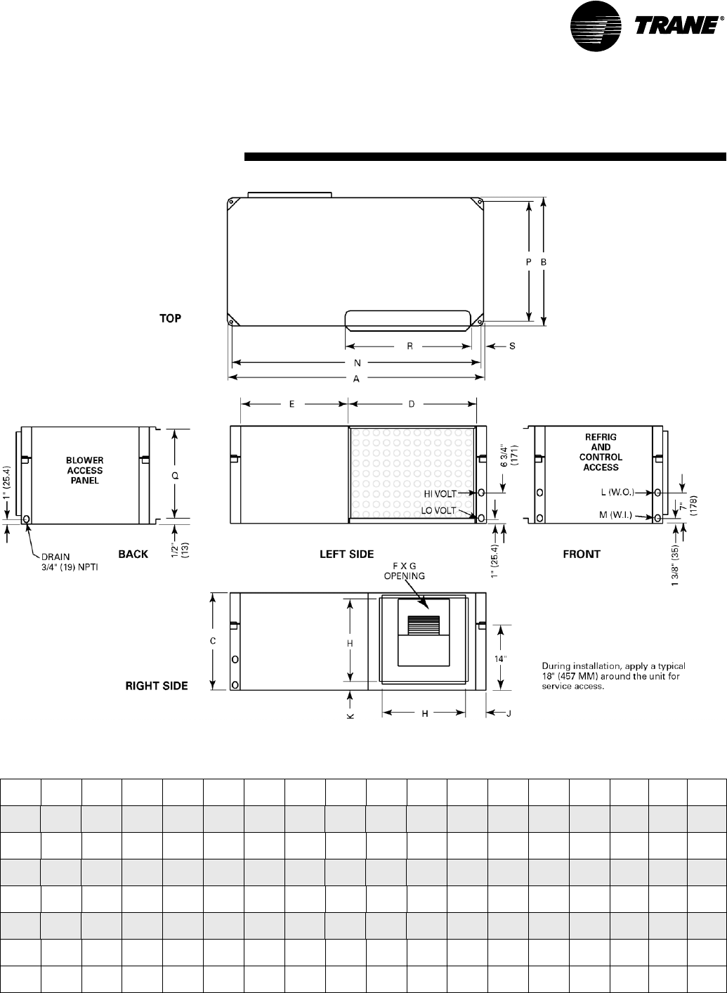
WSHP-PRC001-EN 77
Dimensional Data
Left Return/Right Supply
Unit A B C D E F G H J K L
NPTI
M
NPTI NPQRS
006,009 40"
(1016)
20"
(508)
15"
(381)
20"
(508)
15"
(381)
6 7/8"
(175)
8"
(203)
11 1/2"
(292)
4 1/4"
(108)
1 3/4"
(45)
1/2"
(12.7)
1/2"
(12.7)
38 3/4"
(984)
18 3/4"
(476)
13 5/8"
(346)
18 1/2"
(470)
3 1/4"
(83)
012, 015 40"
(1016)
20"
(508)
15"
(381)
20"
(508)
15"
(381)
6 7/8"
(175)
9 7/8"
(251)
11 1/2"
(292)
4 1/4"
(108)
2 3/4"
(70)
1/2"
(12.7)
1/2"
(12.7)
38 3/4"
(984)
18 3/4"
(476)
13 5/8"
(346)
18 1/2"
(470)
3 1/4"
(83)
018 46"
(1168)
23"
(584)
17"
(432)
23"
(584)
18"
(457)
8 1/4"
(210)
9 3/4"
(248)
13 1/2"
(343)
4 3/4"
(121)
2 1/4"
(57)
3/4"
(19)
3/4"
(19)
44 3/4"
(1137)
21 3/4"
(552)
15 5/8"
(397)
18 1/2"
(470)
4 1/4"
(108)
024, 030 46"
(1168)
23"
(584)
17"
(432)
23"
(584)
18"
(457)
8 1/4"
(210)
11 3/8"
(289)
13 1/2"
(343)
4 3/4"
(121)
2 1/4"
(57)
3/4"
(19)
3/4"
(19)
44 3/4"
(1137)
21 3/4"
(552)
15 5/8"
(397)
18 1/2"
(470)
4 1/4"
(108)
036, 042 50"
(1270)
25"
(635)
19"
(483)
25"
(635)
20"
(508)
10 1/2"
(267)
13 1/2"
(343)
16 3/8"
(416)
4"
(102)
1"
(25.4)
3/4"
(19)
3/4"
(19)
48 3/4"
(1238)
23 3/4"
(603)
17 5/8"
(448)
23 1/2"
(597)
3 1/4"
(83)
Std-048 58"
(1473)
33"
(838)
21"
(533)
23 1/2"
(597)
29 1/2"
(749)
13 1/8"
(333)
11 3/8"
(289)
18"
(457)
6 5/8"
(168)
1 1/2"
(38)
1"
(25.4)
1"
(25.4)
56 3/4"
(1441)
31 3/4"
(806)
19 5/8"
(498)
23 1/2"
(597)
5 1/2"
(140)
Hi-048,
060
58"
(1473)
33"
(838)
21"
(533)
23 1/2"
(597)
29 1/2"
(749)
13 7/8"
(352)
13 7/8"
(352)
18"
(457)
6 5/8"
(168)
1 1/2"
(38)
1"
(25.4)
1"
(25.4)
56 3/4"
(1441)
31 3/4"
(806)
19 5/8"
(498)
23 1/2"
(597)
5 1/2"
(140)
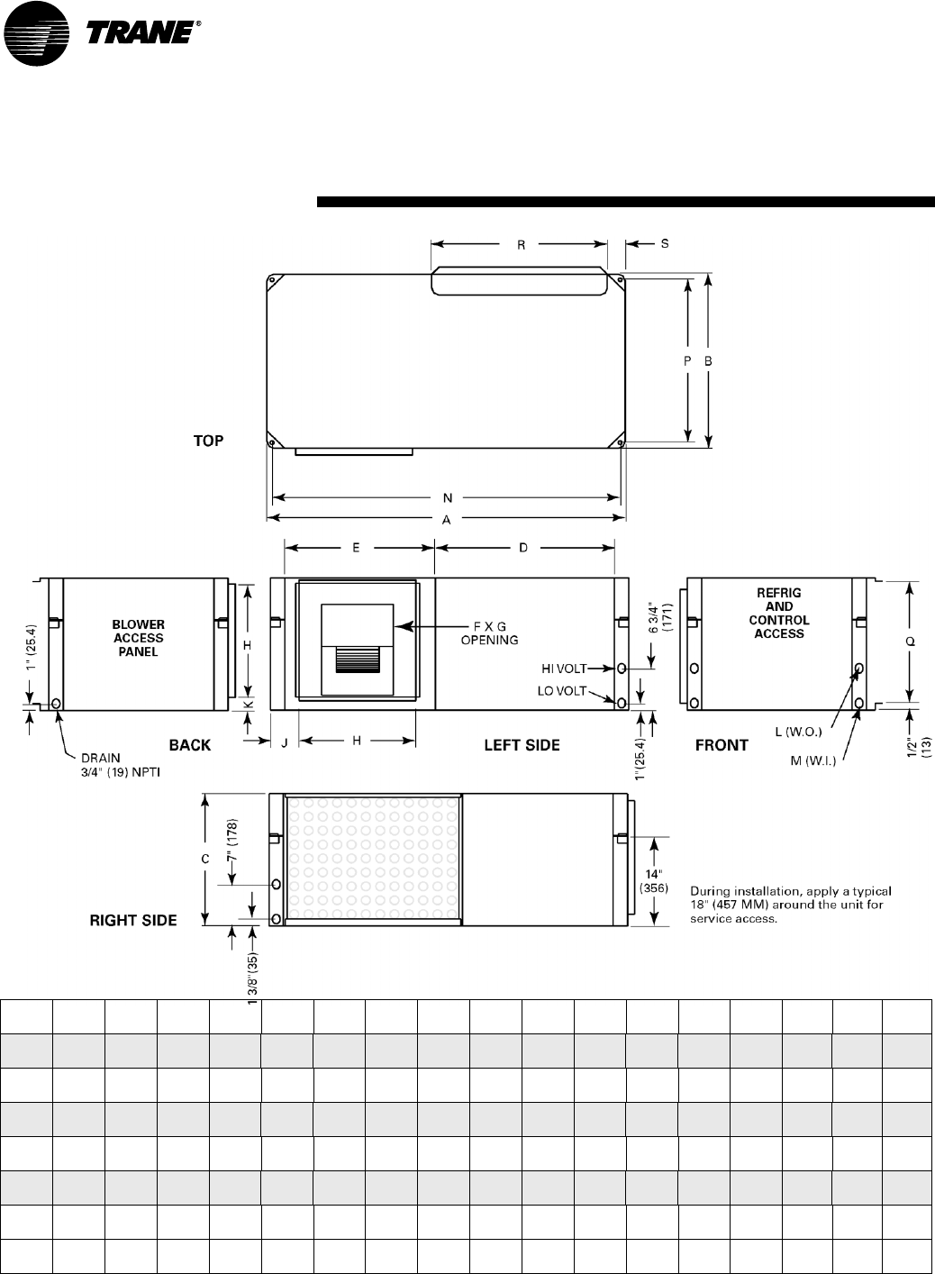
78 WSHP-PRC001-EN
Dimensional Data
Right Return/Left Supply
Unit A B C D E F G H J K L
NPTI
M
NPTI NPQRS
006,009 40"
(1016)
20"
(508)
15"
(381)
20"
(508)
15"
(381)
6 7/8"
(175)
8"
(203)
11 1/2"
(292)
4 1/4"
(108)
1 3/4"
(45)
1/2"
(12.7)
1/2"
(12.7)
38 3/4"
(984)
18 3/4"
(476)
13 5/8"
(346)
18 1/2"
(470)
3 1/4"
(83)
012, 015 40"
(1016)
20"
(508)
15"
(381)
20"
(508)
15"
(381)
6 7/8"
(175)
9 7/8"
(251)
11 1/2"
(292)
4 1/4"
(108)
2 3/4"
(70)
1/2"
(12.7)
1/2"
(12.7)
38 3/4"
(984)
18 3/4"
(476)
13 5/8"
(346)
18 1/2"
(470)
3 1/4"
(83)
018 46"
(1168)
23"
(584)
17"
(432)
23"
(584)
18"
(457)
8 1/4"
(210)
9 3/4"
(248)
13 1/2"
(343)
4 3/4"
(121)
2 1/4"
(57)
3/4"
(19)
3/4"
(19)
44 3/4"
(1137)
21 3/4"
(552)
15 5/8"
(397)
18 1/2"
(470)
4 1/4"
(108)
024, 030 46"
(1168)
23"
(584)
17"
(432)
23"
(584)
18"
(457)
8 1/4"
(210)
11 3/8"
(289)
13 1/2"
(343)
4 3/4"
(121)
2 1/4"
(57)
3/4"
(19)
3/4"
(19)
44 3/4"
(1137)
21 3/4"
(552)
15 5/8"
(397)
18 1/2"
(470)
4 1/4"
(108)
036, 042 50"
(1270)
25"
(635)
19"
(483)
25"
(635)
20"
(508)
10 1/2"
(267)
13 1/2"
(343)
16 3/8"
(416)
4"
(102)
1"
(25.4)
3/4"
(19)
3/4"
(19)
48 3/4"
(1238)
23 3/4"
(603)
17 5/8"
(448)
23 1/2"
(597)
3 1/4"
(83)
Std-048 58"
(1473)
33"
(838)
21"
(533)
23 1/2"
(597)
29 1/2"
(749)
13 1/8"
(333)
11 3/8"
(289)
18"
(457)
6 5/8"
(168)
1 1/2"
(38)
1"
(25.4)
1"
(25.4)
56 3/4"
(1441)
31 3/4"
(806)
19 5/8"
(498)
23 1/2"
(597)
5 1/2"
(140)
Hi-048,
060
58"
(1473)
33"
(838)
21"
(533)
23 1/2"
(597)
29 1/2"
(749)
13 7/8"
(352)
13 7/8"
(352)
18"
(457)
6 5/8"
(168)
1 1/2"
(38)
1"
(25.4)
1"
(25.4)
56 3/4"
(1441)
31 3/4"
(806)
19 5/8"
(498)
23 1/2"
(597)
5 1/2"
(140)
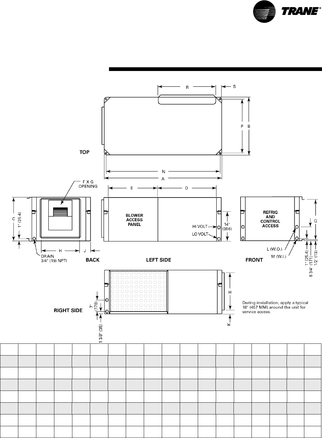
WSHP-PRC001-EN 79
Dimensional Data
Right Return/Back Supply
Unit A B C D E F G H J K L
NPTI
M
NPTI NPQRS
006,009 40"
(1016)
20"
(508)
15"
(381)
20"
(508)
15"
(381)
6 7/8"
(175)
8"
(203)
11 1/2"
(292)
4 1/4"
(108)
1 3/4"
(45)
1/2"
(12.7)
1/2"
(12.7)
38 3/4"
(984)
18 3/4"
(476)
13 5/8"
(346)
18 1/2"
(470)
3 1/4"
(83)
012, 015 40"
(1016)
20"
(508)
15"
(381)
20"
(508)
15"
(381)
6 7/8"
(175)
9 7/8"
(251)
11 1/2"
(292)
4 1/4"
(108)
2 3/4"
(70)
1/2"
(12.7)
1/2"
(12.7)
38 3/4"
(984)
18 3/4"
(476)
13 5/8"
(346)
18 1/2"
(470)
3 1/4"
(83)
018 46"
(1168)
23"
(584)
17"
(432)
23"
(584)
18"
(457)
8 1/4"
(210)
9 3/4"
(248)
13 1/2"
(343)
4 3/4"
(121)
2 1/4"
(57)
3/4"
(19)
3/4"
(19)
44 3/4"
(1137)
21 3/4"
(552)
15 5/8"
(397)
18 1/2"
(470)
4 1/4"
(108)
024, 030 46"
(1168)
23"
(584)
17"
(432)
23"
(584)
18"
(457)
8 1/4"
(210)
11 3/8"
(289)
13 1/2"
(343)
4 3/4"
(121)
2 1/4"
(57)
3/4"
(19)
3/4"
(19)
44 3/4"
(1137)
21 3/4"
(552)
15 5/8"
(397)
18 1/2"
(470)
4 1/4"
(108)
036, 042 50"
(1270)
25"
(635)
19"
(483)
25"
(635)
20"
(508)
10 1/2"
(267)
13 1/2"
(343)
16 3/8"
(416)
4"
(102)
1"
(25.4)
3/4"
(19)
3/4"
(19)
48 3/4"
(1238)
23 3/4"
(603)
17 5/8"
(448)
23 1/2"
(597)
3 1/4"
(83)
Std-048 58"
(1473)
33"
(838)
21"
(533)
23 1/2"
(597)
29 1/2"
(749)
13 1/8"
(333)
11 3/8"
(289)
18"
(457)
6 5/8"
(168)
1 1/2"
(38)
1"
(25.4)
1"
(25.4)
56 3/4"
(1441)
31 3/4"
(806)
19 5/8"
(498)
23 1/2"
(597)
5 1/2"
(140)
Hi-048,
060
58"
(1473)
33"
(838)
21"
(533)
23 1/2"
(597)
29 1/2"
(749)
13 7/8"
(352)
13 7/8"
(352)
18"
(457)
6 5/8"
(168)
1 1/2"
(38)
1"
(25.4)
1"
(25.4)
56 3/4"
(1441)
31 3/4"
(806)
19 5/8"
(498)
23 1/2"
(597)
5 1/2"
(140)
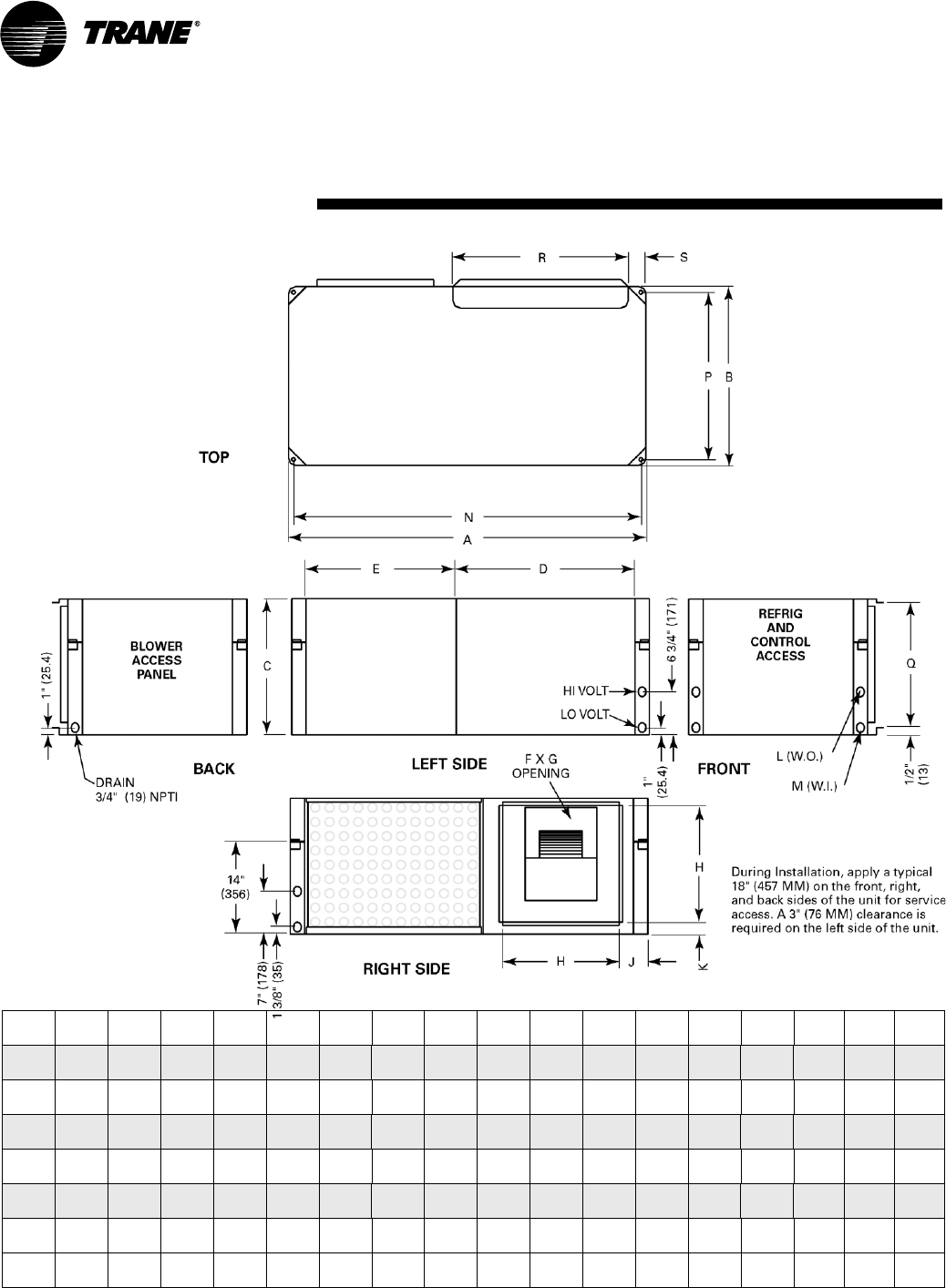
80 WSHP-PRC001-EN
Dimensional Data
Right Return/Right Supply
Unit A B C D E F G H J K L
NPTI
M
NPTI NPQRS
006,009 40"
(1016)
20"
(508)
15"
(381)
20"
(508)
15"
(381)
6 7/8"
(175)
8"
(203)
11 1/2"
(292)
4 1/4"
(108)
1 3/4"
(45)
1/2"
(12.7)
1/2"
(12.7)
38 3/4"
(984)
18 3/4"
(476)
13 5/8"
(346)
18 1/2"
(470)
3 1/4"
(83)
012, 015 40"
(1016)
20"
(508)
15"
(381)
20"
(508)
15"
(381)
6 7/8"
(175)
9 7/8"
(251)
11 1/2"
(292)
4 1/4"
(108)
2 3/4"
(70)
1/2"
(12.7)
1/2"
(12.7)
38 3/4"
(984)
18 3/4"
(476)
13 5/8"
(346)
18 1/2"
(470)
3 1/4"
(83)
018 46"
(1168)
23"
(584)
17"
(432)
23"
(584)
18"
(457)
8 1/4"
(210)
9 3/4"
(248)
13 1/2"
(343)
4 3/4"
(121)
2 1/4"
(57)
3/4"
(19)
3/4"
(19)
44 3/4"
(1137)
21 3/4"
(552)
15 5/8"
(397)
18 1/2"
(470)
4 1/4"
(108)
024, 030 46"
(1168)
23"
(584)
17"
(432)
23"
(584)
18"
(457)
8 1/4"
(210)
11 3/8"
(289)
13 1/2"
(343)
4 3/4"
(121)
2 1/4"
(57)
3/4"
(19)
3/4"
(19)
44 3/4"
(1137)
21 3/4"
(552)
15 5/8"
(397)
18 1/2"
(470)
4 1/4"
(108)
036, 042 50"
(1270)
25"
(635)
19"
(483)
25"
(635)
20"
(508)
10 1/2"
(267)
13 1/2"
(343)
16 3/8"
(416)
4"
(102)
1"
(25.4)
3/4"
(19)
3/4"
(19)
48 3/4"
(1238)
23 3/4"
(603)
17 5/8"
(448)
23 1/2"
(597)
3 1/4"
(83)
Std-048 58"
(1473)
33"
(838)
21"
(533)
23 1/2"
(597)
29 1/2"
(749)
13 1/8"
(333)
11 3/8"
(289)
18"
(457)
6 5/8"
(168)
1 1/2"
(38)
1"
(25.4)
1"
(25.4)
56 3/4"
(1441)
31 3/4"
(806)
19 5/8"
(498)
23 1/2"
(597)
5 1/2"
(140)
Hi-048,
060
58"
(1473)
33"
(838)
21"
(533)
23 1/2"
(597)
29 1/2"
(749)
13 7/8"
(352)
13 7/8"
(352)
18"
(457)
6 5/8"
(168)
1 1/2"
(38)
1"
(25.4)
1"
(25.4)
56 3/4"
(1441)
31 3/4"
(806)
19 5/8"
(498)
23 1/2"
(597)
5 1/2"
(140)
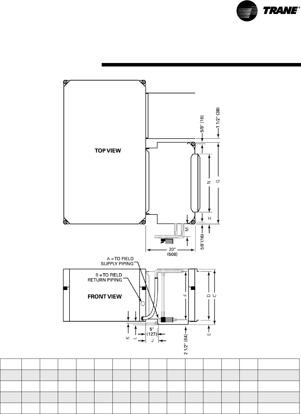
WSHP-PRC001-EN 81
Dimensional Data
Waterside Economizer
Unit A
NPTI
B
NPTI CDEFGHJKLMN Filter Size
(nominal)
006-015 1/2"
(12.7)
1/2"
(12.7)
16 1/8"
(410)
13 5/8"
(346)
1 1/2"
(38)
10 3/4"
(273)
23"
(584)
2 1/4"
(57)
7 1/2"
(191)
1/2"
(12.7)
1"
(25.4)
4"
(102)
18 1/2"
(470)
14 3/4" x 23 3/4"
375 mm x 518 mm
018-030 3/4"
(19)
3/4"
(19)
18 1/2"
(470)
15 5/8"
(397)
1 1/2"
(38)
13 3/4"
(349)
26"
(660)
3 1/4"
(83)
6 7/8"
(175)
1/2"
(12.7)
1"
(25.4)
4"
(102)
18 1/2"
(470)
16 3/4" x 23 3/4"
426 mm x 603 mm
036-042 3/4"
(19)
3/4"
(19)
21"
(533)
17 5/8"
(448)
2 1/4"
(57)
16 1/2"
(419)
30"
(762)
3 3/4"
(95)
6 1/4"
(159)
1 1/4"
(32)
2"
(50.8)
4 1/2"
(114)
23 1/2"
(597)
18 3/4" x 25 1/2"
476 mm x 648 mm
048, 060 1"
(25.4)
1"
(25.4)
23 1/8"
(587)
19 5/8"
(498)
2 1/2"
(64)
19 1/2"
(495)
34"
(864)
5 1/4"
(133)
5 7/8"
(149)
1 1/4"
(32)
2"
(50.8)
4 1/2"
(114)
23 1/2"
(597)
20 3/4" x 29 7/8"
528 mm x 759 mm
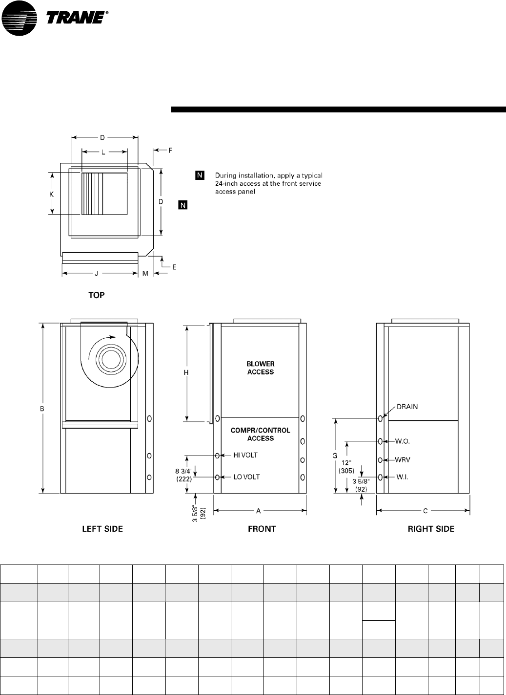
82 WSHP-PRC001-EN
Dimensional Data
Left Return/Top Supply
Unit
GEV AB C D E F G H J K L M
W.I.
NPTI
W.O.
NPTI
Drain
FPT
006-015 19 1/2"
(495)
31 1/4"
(794)
21 1/2"
(546)
11 1/2"
(292)
4"
(102)
5 3/4"
(146)
16 1/2"
(419)
14 7/8"
(378)
17"
(432)
6 7/8"
(175)
8"
(203)
3 3/4"
(95)
1/2"
(12.7)
1/2"
(12.7)
3/4"
(19)
018, 024,
030, 040
21 1/2"
(546)
39 1/4"
(997)
21 1/2"
(546)
13 1/2"
(343)
4"
(102)
4"
(1021)
17 1/2"
(445)
24"
(610)
18"
(457)
8 1/4"
(368)
9 3/4"
(248) 1 7/8"
(48)
3/4"
(19)
3/4"
(19)
3/4"
(19)
11 1/2"
(292)
036, 042 24 1/2"
(622)
41 7/8"
(1064)
26 1/2"
(673)
18"
(457)
3 1/4"
(83)
4"
(1021)
19 1/2"
(495)
19"
(483)
23"
(584)
10 1/2"
(267)
13 3/4"
(349)
3 1/4"
(83)
3/4"
(19)
3/4"
(19)
3/4"
(19)
Std-048 26 1/2"
(673)
46 7/8"
(1191)
30 1/2"
(775)
18"
(457)
4 1/4"
(108)
9 3/4"
(248)
21 1/2"
(546)
28 7/8"
(733)
27"
(686)
13 7/8"
(352)
13 7/8"
(352)
3 1/4"
(83)
1"
(25.4)
1"
(25.4)
3/4"
(19)
Hi-048,
060
26 1/2"
(673)
46 7/8"
(1191)
30 1/2"
(775)
18"
(457)
4 1/4"
(108)
9 3/4"
(248)
21 1/2"
(546)
28 7/8"
(733)
27"
(686)
13 1/8"
(333)
11 3/8"
(289)
3 1/4"
(83)
1"
(25.4)
1"
(25.4)
3/4"
(19)
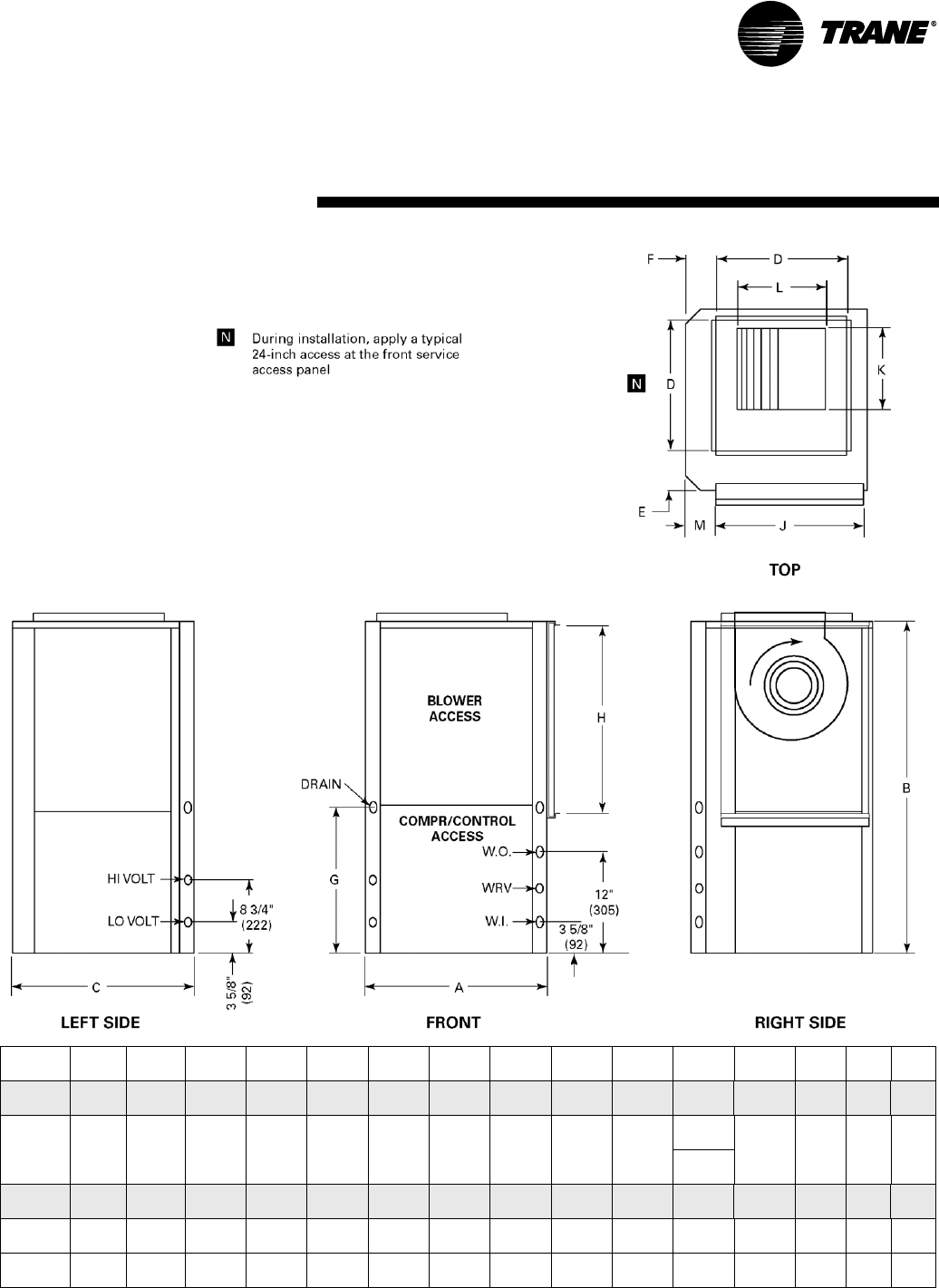
WSHP-PRC001-EN 83
Dimensional Data
Right Return/Top Supply
Unit
GEV AB C D E F G H J K L M
W.I.
NPTI
W.O.
NPTI
Drain
FPT
006-015 19 1/2"
(495)
31 1/4"
(794)
21 1/2"
(546)
11 1/2"
(292)
4"
(102)
5 3/4"
(146)
16 1/2"
(419)
14 7/8"
(378)
17"
(432)
6 7/8"
(175)
8"
(203)
3 3/4"
(95)
1/2"
(12.7)
1/2"
(12.7)
3/4"
(19)
018, 024,
030, 040
21 1/2"
(546)
39 1/4"
(997)
21 1/2"
(546)
13 1/2"
(343)
4"
(102)
4"
(1021)
17 1/2"
(445)
24"
(610)
18"
(457)
8 1/4"
(368)
9 3/4"
(248) 1 7/8"
(48)
3/4"
(19)
3/4"
(19)
3/4"
(19)
11 1/2"
(292)
036, 042 24 1/2"
(622)
41 7/8"
(1064)
26 1/2"
(673)
18"
(457)
3 1/4"
(83)
4"
(1021)
19 1/2"
(495)
19"
(483)
23"
(584)
10 1/2"
(267)
13 3/4"
(349)
3 1/4"
(83)
3/4"
(19)
3/4"
(19)
3/4"
(19)
Std-048 26 1/2"
(673)
46 7/8"
(1191)
30 1/2"
(775)
18"
(457)
4 1/4"
(108)
9 3/4"
(248)
21 1/2"
(546)
28 7/8"
(733)
27"
(686)
13 7/8"
(352)
13 7/8"
(352)
3 1/4"
(83)
1"
(25.4)
1"
(25.4)
3/4"
(19)
Hi-048,
060
26 1/2"
(673)
46 7/8"
(1191)
30 1/2"
(775)
18"
(457)
4 1/4"
(108)
9 3/4"
(248)
21 1/2"
(546)
28 7/8"
(733)
27"
(686)
13 1/8"
(333)
11 3/8"
(289)
3 1/4"
(83)
1"
(25.4)
1"
(25.4)
3/4"
(19)
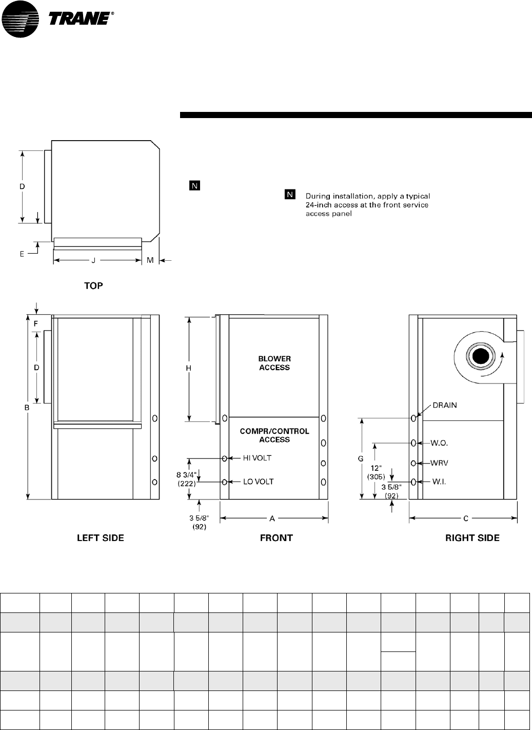
84 WSHP-PRC001-EN
Dimensional Data
Left Return/Back Supply
Unit
GEV AB C D E F G H J K L M
W.I.
NPTI
W.O.
NPTI
Drain
FPT
006-015 19 1/2"
(495)
31 1/4"
(794)
21 1/2"
(546)
11 1/2"
(292)
4"
(102)
5 3/4"
(146)
16 1/2"
(419)
14 7/8"
(378)
17"
(432)
6 7/8"
(175)
8"
(203)
3 3/4"
(95)
1/2"
(12.7)
1/2"
(12.7)
3/4"
(19)
018, 024,
030, 040
21 1/2"
(546)
39 1/4"
(997)
21 1/2"
(546)
13 1/2"
(343)
4"
(102)
4 3/8"
(111)
17 1/2"
(445)
24"
(610)
18"
(457)
8 1/4"
(368)
9 3/4"
(248) 1 7/8"
(48)
3/4"
(19)
3/4"
(19)
3/4"
(19)
11 1/2"
(292)
036, 042 24 1/2"
(622)
41 7/8"
(1064)
26 1/2"
(673)
18"
(457)
5 3/4"
(146)
4"
(1021)
19 1/2"
(495)
19"
(483)
23"
(584)
10 1/2"
(267)
13 3/4"
(349)
3 1/4"
(83)
3/4"
(19)
3/4"
(19)
3/4"
(19)
Std-048 26 1/2"
(673)
46 7/8"
(1191)
30 1/2"
(775)
18"
(457)
4 1/4"
(108)
9 3/4"
(248)
21 1/2"
(546)
28 7/8"
(733)
27"
(686)
13 7/8"
(352)
13 7/8"
(352)
3 1/4"
(83)
1"
(25.4)
1"
(25.4)
3/4"
(19)
Hi-048,
060
26 1/2"
(673)
46 7/8"
(1191)
30 1/2"
(775)
18"
(457)
4 1/4"
(108)
9 3/4"
(248)
21 1/2"
(546)
28 7/8"
(733)
27"
(686)
13 1/8"
(333)
11 3/8"
(289)
3 1/4"
(83)
1"
(25.4)
1"
(25.4)
3/4"
(19)
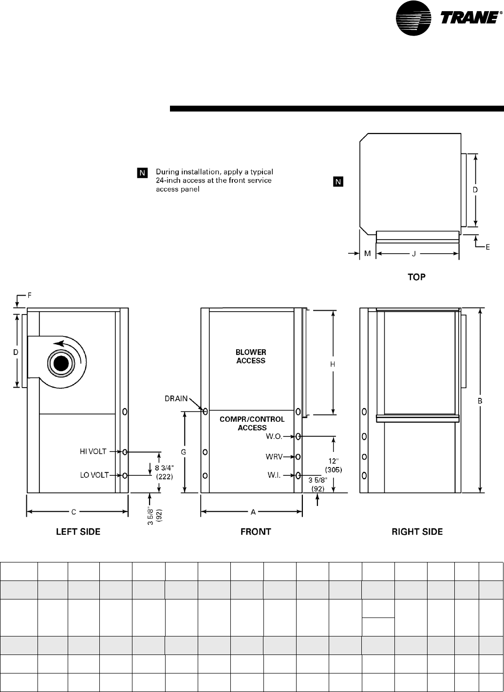
WSHP-PRC001-EN 85
Dimensional Data
Right Return/Back Supply
Unit
GEV AB C D E F G H J K L M
W.I.
NPTI
W.O.
NPTI
Drain
FPT
006-015 19 1/2"
(495)
31 1/4"
(794)
21 1/2"
(546)
11 1/2"
(292)
4"
(102)
5 3/4"
(146)
16 1/2"
(419)
14 7/8"
(378)
17"
(432)
6 7/8"
(175)
8"
(203)
3 3/4"
(95)
1/2"
(12.7)
1/2"
(12.7)
3/4"
(19)
018, 024,
030, 040
21 1/2"
(546)
39 1/4"
(997)
21 1/2"
(546)
13 1/2"
(343)
4"
(102)
4 3/8"
(111)
17 1/2"
(445)
24"
(610)
18"
(457)
8 1/4"
(368)
9 3/4"
(248) 1 7/8"
(48)
3/4"
(19)
3/4"
(19)
3/4"
(19)
11 1/2"
(292)
036, 042 24 1/2"
(622)
41 7/8"
(1064)
26 1/2"
(673)
18"
(457)
5 3/4"
(146)
4"
(1021)
19 1/2"
(495)
19"
(483)
23"
(584)
10 1/2"
(267)
13 3/4"
(349)
3 1/4"
(83)
3/4"
(19)
3/4"
(19)
3/4"
(19)
Std-048 26 1/2"
(673)
46 7/8"
(1191)
30 1/2"
(775)
18"
(457)
4 1/4"
(108)
9 3/4"
(248)
21 1/2"
(546)
28 7/8"
(733)
27"
(686)
13 7/8"
(352)
13 7/8"
(352)
3 1/4"
(83)
1"
(25.4)
1"
(25.4)
3/4"
(19)
Hi-048,
060
26 1/2"
(673)
46 7/8"
(1191)
30 1/2"
(775)
18"
(457)
4 1/4"
(108)
9 3/4"
(248)
21 1/2"
(546)
28 7/8"
(733)
27"
(686)
13 1/8"
(333)
11 3/8"
(289)
3 1/4"
(83)
1"
(25.4)
1"
(25.4)
3/4"
(19)
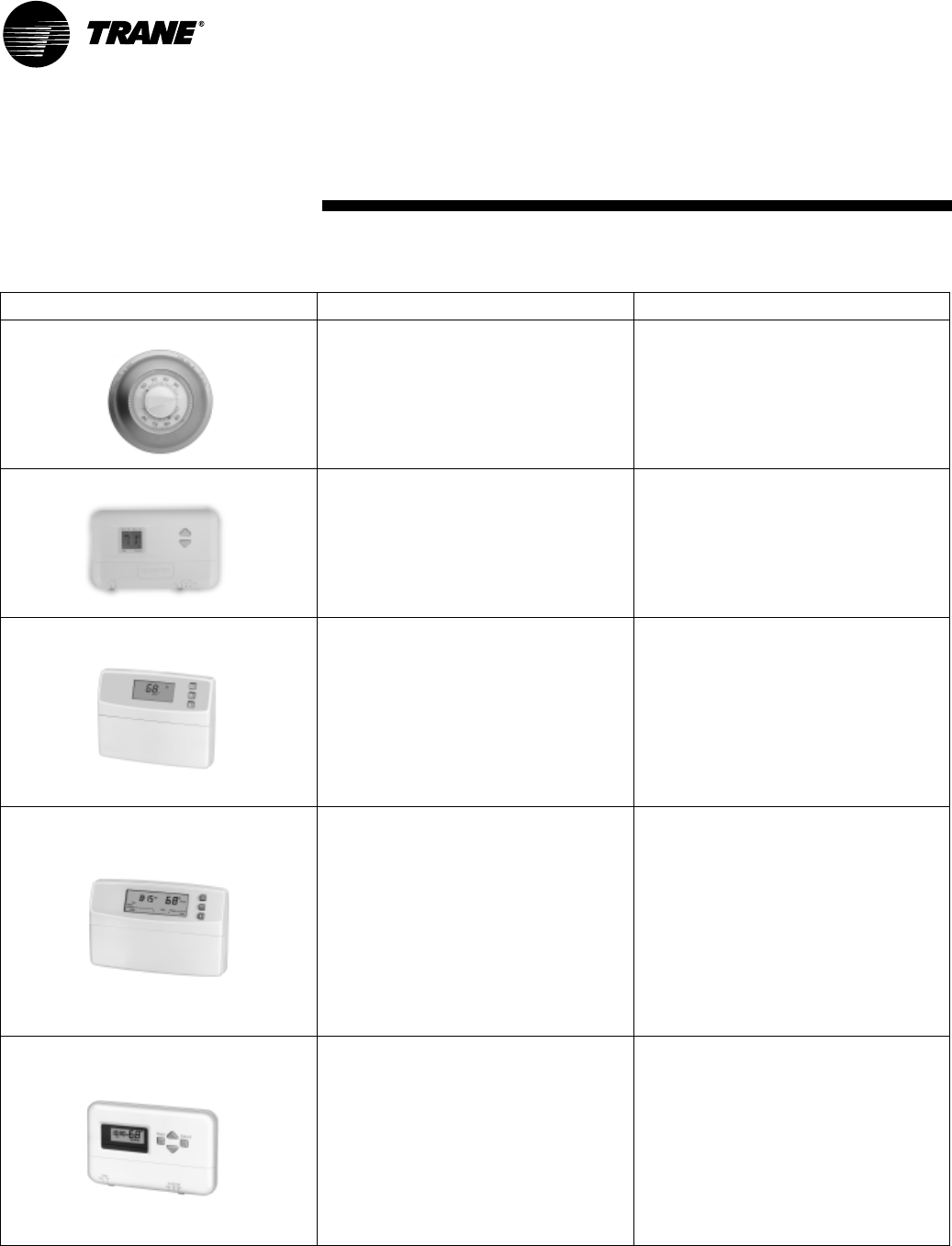
86 WSHP-PRC001-EN
Thermostat/Sensor Selections
Thermostat/Sensor Part Number Description
X13510309010 - thermostat
X13530069010 - subbase
Mercury Thermostat
• 0-stage heat/1-stage cool manual
changeover with COOL-OFF
• Non Programmable
• Fan switching includes
FAN ON-AUTO
X13511039010 Manual Changeover Digital Stat
• 2-stage heat/1-stage cool
• System switching includes
HEAT-OFF-COOL
• Fan switching includes AUTO-ON
• Non programmable
X13511041010 Auto/Manual Changeover
Digital Stat
• 1-stage heat/1-stage cool
• System switching includes
HEAT-OFF-COOL-AUTO
• Fan switching includes
ON-AUTO
• Non programmable
X13511042010 Auto/Manual Changeover
Digital Stat
• 3-stage heat/2-stage cool
• System switching includes
HEAT-OFF-COOL-AUTO
• Fan switching includes
ON-AUTO
• 7-day programmable
• Adjustable 1 to 15-degree night
setback
X13511043010 Manual Changeover Digital Stat
• 2-stage heat/1-stage cool
• System switching includes
HEAT-OFF-COOL
• Fan switching includes
ON-AUTO
• 5-day programmable
• Adjustable 1 to 15-degree night
setback
Accessories
Remote Thermostats
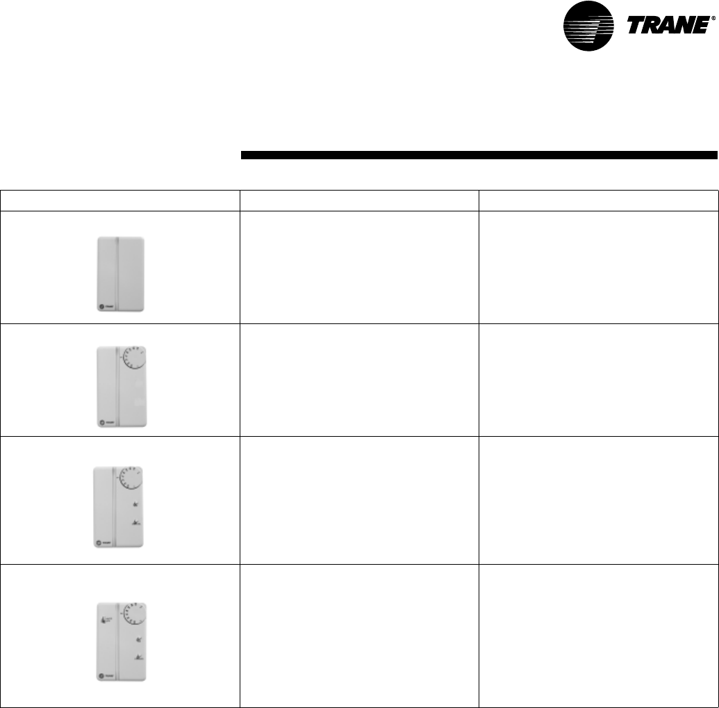
WSHP-PRC001-EN 87
Accessories
Remote T’stats/Zone Sensors
Thermostat/Sensor Part Number Description
X13510628010 Zone Sensor
• Tracer ZN510 and ZN524
compatible
• Internal setpoint adjustment
wheel
• Communication Jack
X13510606010 Zone Sensor
• Tracer ZN510 and ZN524
compatible
• External setpoint adjustment
wheel
• Communication Jack
X13510606020 Zone Sensor
• Tracer ZN510 and ZN524
compatible
• External setpoint adjustment
wheel
• Communication Jack
• ON and CANCEL buttons
X13510635010 Zone Sensor
• Tracer ZN510 and ZN524
compatible
• External setpoint adjustment
wheel
• Communication Jack
• ON and CANCEL buttons
• Fan switch AUTO-OFF
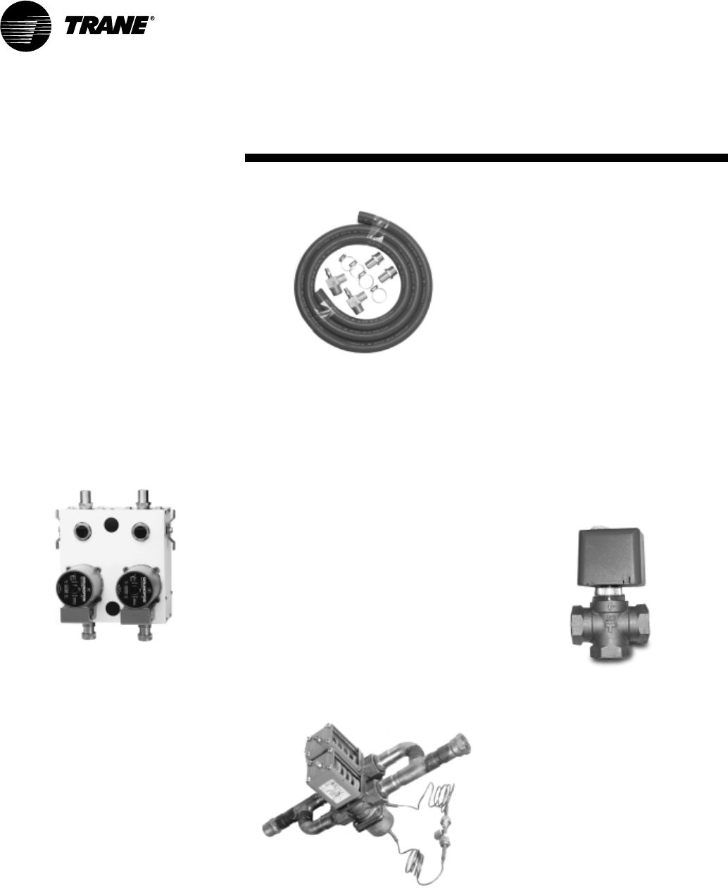
88 WSHP-PRC001-EN
Accessories
Figure 41: Pump module hose kit
Water Regulating Valve
Assembly
The water regulating valve assembly
consists of a direct acting valve and a
reverse acting valve installed on the
water-out side of the unit. The valve
connection sizes shall range from 1/2"
to 1 1/2" FPT. The direct acting valve
opens in response to an increase in
discharge pressure during the cooling
cycle. The reverse acting valve opens
in response to a decrease in suction
pressure during the heating cycle. Wa-
ter regulating valves should be used
where low flow and low or high fluid
temperature conditions could occur.
See page 29 of this manual for applica-
tion information.This option is benefi-
cial with open loop systems, but not
necessary. See Figure 42 for water reg-
ulating valve assembly.
Figure 42: Water regulating valve
Motorized Water Valve
The motorized water valve is installed
on the return line of the water loop
system between the loop and the
loop’s pump module. This isolation
device is less expensive and a very ef-
fective alternative to the water regulat-
ing valve.
When the compressor begins running,
the valve will open, allowing water to
flow through the unit. As the compres-
sor shuts down, the valve slowly clos-
es off. The main purpose of the
motorized valve is to shut-off the flow
of water through the unit when the
unit is off, thus reducing water con-
sumption. The motorized valve is fast
opening to prevent compressor
trip-out, and slow closing to prevent
water hammer. See Figure 43 for mo-
torized water valve.
Figure 43: Motorized water valve
Pump Module
The pump module and hose kit make a
complete self-contained pumping
package for distributed pumping sys-
tems. These kits contain all the neces-
sary components for the installation,
operation and maintenance of the wa-
ter circuit of a closed loop geothermal
application. Standard pump module
features include insulated Grundfos
pumps, insulated cabinet, bronze or
cast iron pump, and 3-way brass
valves. The module is factory piped,
wired and mounted. See Figure 40 for
pump module assembly. Literature
number WSHPC-IN-5 (72-9006-03) will
provide electrical and dimensional re-
quirements for the PMCA and PMBA
products.
Figure 40: Pump module
Pump Module Hose Kit
The pump module hose kit consists of
two brass, 3/4 or 1-inch male pipe
thread (MPT) -by-barb fittings; two
brass 90 degree 1-inch, MPT-by-barb
elbows with pressure/temperature
ports; and 10 feet of rubber hose with
4 hose clamps. The pump module
hose kit is available separately from
the pump module. See Figure 41 for
pump module hose kit.
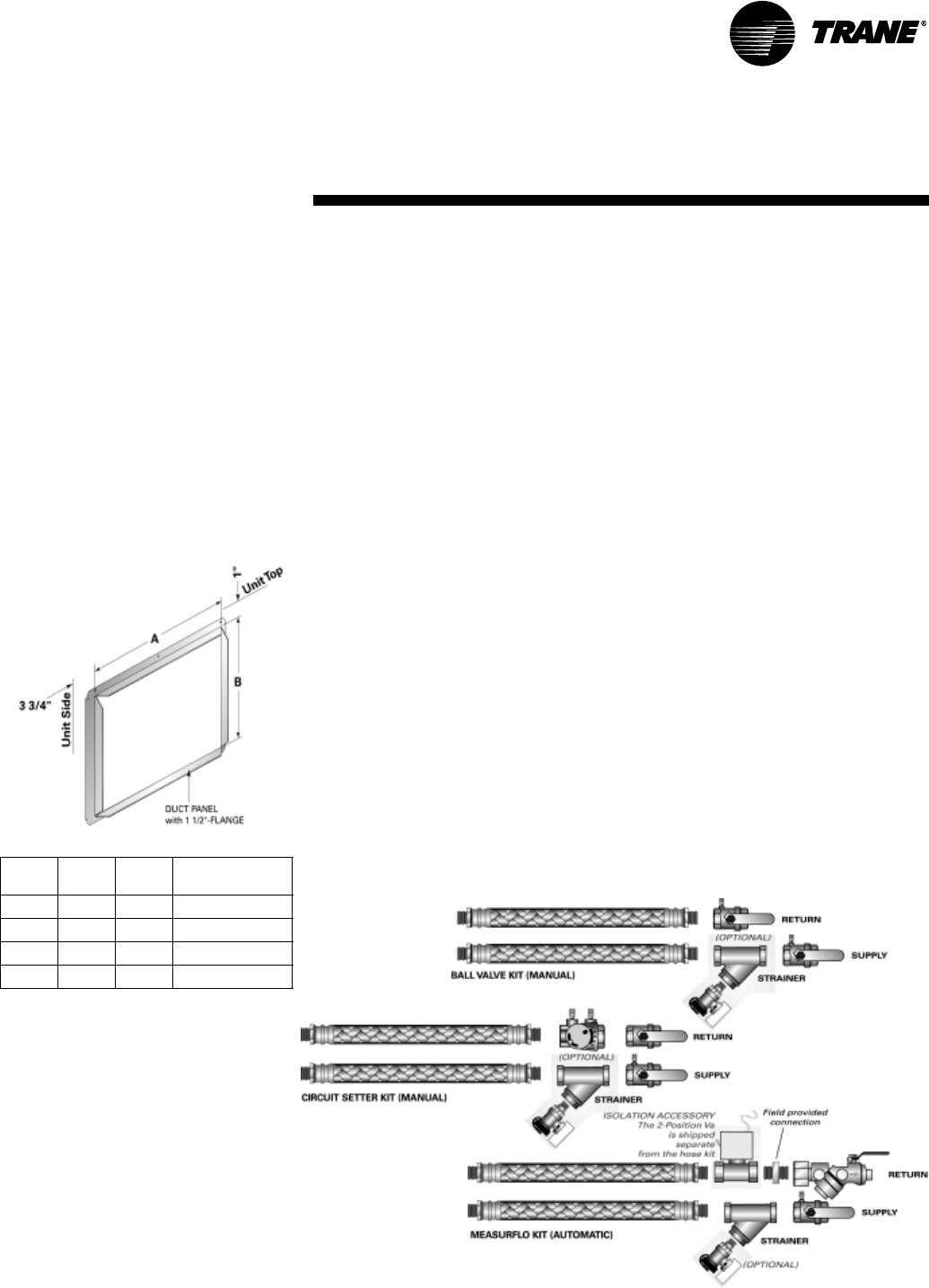
WSHP-PRC001-EN 89
Ducted Panel
The return-air arrangement may be
easily converted from a free return-air
system, to a ducted return-air system
with the addition of a return-air side
panel. By replacing the filter racks with
the return-air panel, a complete seal
from the duct to the unit is possible.
The 1 1/2" duct flange facilitates ease
of field connection to the mechanical
system. This accessory is typically
used when the return-air filter is
placed in a built-in ceiling grille, or
placed within a field provided filter
rack assembly. See Figure 44 for re-
turn-air duct panel.
Figure 44: Return-air duct panel
Unit
Size A B Part Number
006-015 17 1/2" 13" 4474 1133 0100
018-030 20 1/2" 15" 4474 1134 0100
036-042 22 1/2" 17" 4474 1135 0100
048-060 26 1/2" 19" 4474 1136 0100
Hose Kits
Trane provides three hose kit selections for equipment balancing.
• Ball valve flow control
(manual)
• Circuit setter flow control
(manual)
• Automatic flow control
(automatic)
Each selection provides some accuracy in equipment balancing. Range of accu-
racy consist of ±25% for the ball valve method, ±20% for the circuit setter method,
and ±10% for the automatic flow control method.
Utilizing the ball valve method, the pressure/temperature measurement on the
leaving and entering side of the heat pump is measured within the water piping.
The ball valve is then throttled to change the amount of flow to the unit to reach
the desired temperature or pressure differential.
The circuit setter method combines both the readout and the adjustment feature
in one device. In order to determine flow rate, the user must record both handle
position, and differential pressure drop. Then, the user must consult a chart con-
taining both pieces of information to make the necessary adjustments to the cir-
cuit setter.
For automatic system balancing of a water-source heat pump, the
Mesurflo® self balancing kit provides a constant flow rate over the pressure dif-
ferential rage of 2 to 80 psid. As system pressure changes (through further addi-
tion of heat pumps, for example) each individual flow control valve will
automatically adjust to the new system conditions. In variable water volume ap-
plications, a self balancing hose kit can provide continuous balancing because of
its ability to automatically adjust to the varying system conditions. For more in-
formation pertaining to the automatic balancing hose kits, see literature
documentation WSHP-SLB005-EN. See Figure 45 for system balancing hose kits.
Accessories
Figure 45: System balancing hose kits

90 WSHP-PRC001-EN
General
Equipment shall be completely assem-
bled, piped, internally wired, fully
charged with HCFC-22 and test operat-
ed at the factory. Filters, thermostat
field interface terminal strip, and all
safety controls are furnished and fac-
tory installed.
The system water inlet and outlet con-
nections shall be female NPT com-
posed of either a copper or a bronze
option.
The 5-ton and below equipment shall
contain ETL, CETL and ISO-ARI
13256-1 listings and labels prior to
leaving the factory. Larger units shall
be rated in accordance with ISO-ARI
13256-1. Service and caution area la-
bels shall also be placed on the unit in
their appropriate locations.
Cabinet
Unit casing shall be constructed of zinc
coated, heavy gauge, galvanized steel.
Service to the refrigerant and controls
shall be provided through a single ac-
cess panel at the front of the equip-
ment. Access to the refrigerant and
controls for the larger units shall be
provided through the front and side
access panels.
All panels shall be insulated with
1/2-inch thick dual density bonded
glass fiber. The exposed side is a high
density erosion proof material suitable
for use in air streams up to 3600 feet
per minute (FPM). The insulation
meets the erosion requirements of UL
181. It has a flame spread of less than
25 and a smoke developed classifica-
tion of less than 50 per ASTM E-84 and
UL 723.
Access for inspection and cleaning of
the unit drain pan, coils and fan sec-
tion shall be provided. The unit shall
be installed for proper access.
Filters
One inch or two inch, throwaway
filters shall be standard and factory in-
stalled. The filters shall have an aver-
age resistance of 76-percent and dust
holding capacity of 26-grams per
square foot.
Sound Attenuation
Sound attenuation shall be applied as
a standard feature in the product de-
sign. The sound reduction package
shall include a compressor discharge
muffler, vibration isolation to the com-
pressor and water-to-refrigerant coil,
unit base stiffeners, insulated metal
compressor enclosure, and a second
stage of vibration isolation to the com-
pressor and water-to-refrigerant base
pan.
All units shall be tested and rated in
accordance with ARI 260.
Compressors
The unit shall contain a high efficiency
rotary, reciprocating, or scroll com-
pressor. External vibration isolation
shall be provided by rubber mounting
devices located underneath the
mounting base of the compressor. A
second isolation of the refrigeration
assembly shall be supported under
the compressor mounting base.
Internal thermal overload protection
shall be provided. Protection against
excessive discharge pressure shall be
provided by means of a high pressure
switch. A loss of charge shall be pro-
vided by a low pressure safety.
Refrigerant Tubing
The refrigerant tubing shall be of 99%
pure copper. This system shall be free
from contaminants and conditions
such as drilling fragments, dirt and oil.
All refrigerant and water lines shall be
insulated with an elastomeric insula-
tion that has a 3/8-inch thick wall in the
air-side section of the unit.
Refrigerant Circuits
The refrigerant circuit shall contained
a thermal expansion device. Service
pressure ports shall be factory sup-
plied on the high and low pressure
sides for easy refrigerant pressure or
temperature testing.
Air-to-Refrigerant Coil
Internally finned, 3/8-inch copper
tubes mechanically bonded to a con-
figured aluminum plate fin shall be
standard. Coils shall be leak tested at
the factory to ensure the pressure in-
tegrity. The coil shall be leak tested to
200 psig and pressure tested to 450
psig. The tubes are to be completely
evacuated of air and correctly charged
with proper volume of refrigerant pri-
or to shipment.
The refrigerant coil distributor assem-
bly shall be of orifice style with round
copper distributor tubes. The tubes
shall be sized consistently with the ca-
pacity of the coil. Suction header shall
be fabricated from rounded copper
pipe.
A thermostatic expansion valve shall
be factory selected and installed for a
wide range of control.
Drain Pan
The condensate pan shall be con-
structed of corrosion resistant materi-
al and insulated to prevent sweating.
The bottom of the drain pan shall be
sloped on two planes which pitches
the condensate to the drain connec-
tion. The drain pan shall be flame rat-
ed per UL945V-B. When the unit is
installed and trapped per the manufac-
turers installation manual, and local
city specifications, the drain pan shall
be designed to leave puddles no more
than 2-inch in diameter, no more than
1/8-inch deep, no longer than 3-min-
utes following the step 3 of the follow-
ing test.
1 Temporarily plug the drain pan.
2 Fill the drain pan with 1/2-inch of
water or the maximum allowed
by the drain pan depth, which-
ever is smaller.
3 Remove the temporary plug.
Mechanical
Specifications

WSHP-PRC001-EN 91
Water-to-Refrigerant
Heat Exchanger
The water-to-refrigerant heat ex-
changer shall be of a high quality
co-axial coil for maximum heat trans-
fer. The copper or optional cupro-nick-
el coil shall be deeply fluted to
enhance heat transfer and minimize
fouling and scaling. The coil shall have
a working pressure of 400 psig on both
the refrigerant and water sides. The
factory shall provide rubber isolation
to the heat exchanging device to en-
hance sound attenuation.
Indoor Fan
The blower shall be a forward-curved
style wheel with four speed combina-
tions, or nine blower motor/sheave
combinations available.
All direct drive motors shall have
sealed bearings that do not require
field lubrication.
Options of the blower motor/fan pack-
ages shall be selected and wired from
the factory to match performance cri-
teria suggested in the performance
section. The motor shall contain a
quick disconnect plug for service, con-
vertibility and safety precautions.
The fan(s) shall be placed in a
draw-through configuration. They
shall be constructed of corrosion resis-
tant galvanized material.
Electrical
The unit control box shall contain all
necessary devices to allow heating
and cooling operation to occur from a
remote wall thermostat. These devices
shall be as follows:
• 24 VAC energy limiting class II
50 VA (minimum) transformer
• 24 VAC blower motor relay
• 24 VAC compressor contactor for
compressor control
• Field thermostat connections shall
be provided for ease of hook-up to
a terminal strip located in the
unit’s control box
• Lockout relay which controls cy-
cling of the compressor shall be
provided to protect the compres-
sor during adverse operating con-
ditions. The device may be reset
by interrupting power to the 24
VAC control circuit. Reset may be
done either at a remote thermo-
stat or through a momentary main
power interruption
• A high pressure switch shall pro-
tect the compressor against oper-
ation at refrigerant system
pressures exceeding 395 psig.
• The low-water temperature switch
or sensor shall prevent the com-
pressor operation with leaving
water temperatures below 20 F.
• Factory installed wire harness shall
be available for the Basic, Deluxe,
ZN510 and ZN524 control packag-
es.
Nameplate information shall be pro-
vided for the application of either
time-delay fuses or HACR circuit
breakers for branch circuit protection
from the primary source of power.
Basic Controls (option)
The basic control package shall con-
tain a low and high pressure switch
along with a compressor lockout relay
for control assistance. High voltage
power connections shall be made at
the equipments contactor. An optional
condensate overflow detection device
shall be made available with this con-
trol package. Each device shall be fac-
tory mounted, wired, and tested in the
equipment.
Deluxe Controls (option)
The deluxe control package shall pro-
vide a 75 VA transformer with circuit
breaker. The controller shall include a
lockout relay, anti-short cycle com-
pressor protection, random start de-
lay, brown-out protection, low
pressure time delay, compressor de-
lay on start and an open relay for night
setback or pump request. Optional
wiring from the factory for night set-
back, condensate overflow, hot gas re-
heat, electric heat, and compressor
enable shall also be provided. Three
LEDs (light emitting diodes) shall also
be included for diagnostics of the
equipment.
Tracer ZN510 or ZN524 Controller
(option)
This system shall utilize factory fur-
nished and mounted DDC controls for
operation of up to 120 units on a
Comm 5 (LonMark) link. The Tracer
ZN510 control package shall include a
75 VA transformer. The controller shall
provide random start delay, heating/
cooling status, occupied/unoccupied
mode, fan status and filter mainte-
nance options. Optional wiring from
the factory for condensate overflow
shall be available. Three LEDs (light
emitting diodes) shall be included for
diagnostics of the equipment.
The ZN510 shall be capable of a stan-
dalone application, or as applied to a
full building automation installation.
Mechanical
Specifications

92 WSHP-PRC001-EN
Tracer ZN524 Controller (option)
The ZN524 controller shall utilize fac-
tory furnished and mounted DDC con-
trols for operation of up to 120 units on
a Comm 5 (LonMark) link. The Tracer
ZN524 control package shall include a
75 VA (minimum) transformer. The
controller shall provide random start
delay, heating/cooling status, occu-
pied/unoccupied mode, fan status and
filter maintenance options. Optional
wiring from the factory for condensate
overflow shall be available. Three
LEDs (light emitting diodes) shall be
included for diagnostics of the equip-
ment.
The ZN524 shall be capable of a stan-
dalone application, or as applied to a
full building automation installation.
With this controller, the unit shall be
capable of a hot gas reheat (for dehu-
midification), boilerless control for
electric heat, waterside economizing,
and support of variable speed pump
control applications.
Orifice Ring
Removal of the motor and fan wheel
for the 1/2 through 5-ton units shall be
made with the assistance of a factory
provided orifice ring device. This de-
vice shall attach the wheel and motor
to the fan housing in one assembly
providing single side service access.
Water Regulating Valve
Assembly (option)
The water regulating valve assembly
shall consist of a direct acting valve
and a reverse acting valve. The direct
acting valve shall open in response to
an increase in discharge pressure dur-
ing the cooling cycle. The reverse act-
ing valve shall open in response to a
decrease in suction pressure during
the heating cycle. Water regulating
valves shall be used where low flow,
or low or high fluid temperature condi-
tions exist. This accessory shall be
used with open-loop systems.
Economizing Coil (GEH option)
The waterside economizing package
shall be an external unit accessory
pre-piped and pre-wired ready for
turn-key installation to the unit. The
economizing coil shall be designed to
perform with the WSHP at unit mea-
sured flow rate of 80.6 F DB/66.2 F WB
with 45 F EWT.
All hydronic coils shall be of 5/8" cop-
per and aluminum plate fin combina-
tion. All coils shall be proof and leak
tested from the manufacturer. The
proof test shall be performed at 1.5
times the maximum operating pres-
sure and the leak test at the maximum
operating pressure.
A dual sloped non corrosive drain pan
shall be easily accessible and clean-
able for the hydronic economizing
coil.
An electronic two-position, 3-way
valve shall meter water flow to the
economizing coil during the econo-
mizing mode. It shall be factory set to
energize the economizing mode at
55 F, while simultaneously halting me-
chanical operation of the compressor.
Hanging brackets with rubber isola-
tion shall be provided for the horizon-
tal version of the economizing coil
option. The bracket design shall be the
same throughout the equipment.
Electric Heat (option)
Boilerless control electric heat shall be
factory wired and tested. It shall be
composed of a nichrome open wire
coil designed for 2-kW per unit ton.
The design consist of a single stage of
electric heat used as a primary heating
source when compressor lockout has
occurred due to the entering water
temperature falling below 55 F with an
adjustable range between 25 F to 60 F.
All power connections to the electric
heat shall be made in the equipment’s
control box.
Hot Gas Reheat (option)
Dehumidification shall be provided
through a hot gas reheat option. The
coil shall consist of 3/8"/1/2" copper
tubes mechanically expanded into
evenly spaced aluminum fins. All coils
shall be proof and leak tested. The
proof test must be performed at 1.5
time the maximum operating pressure
and the leak test performed at the
maximum operating pressure.
Ball Valves (option)
Ball valves shall be field installed be-
tween the unit and the supply and re-
turn lines of the loop to stop water
flow to the unit in a maintenance or
service situation.
Motorized Water Valve (option)
When extreme fluid temperature con-
ditions do not exist with an open loop
system, a motorized water valve shall
be applied to each water-source heat
pump. The motorized valve shall stop
flow to the unit, causing pressures to
rise. This rise in pressure will halt
pump operation to provide greater en-
ergy savings of the entire system.
Mechanical
Specifications

WSHP-PRC001-EN 93
Pump Module (option)
The pump module shall be a complete
self contained pumping package for
an earth-coupled heat pump system.
The module shall consist of a single,
1/6-HP bronze pump, and a brass
3-way shut-off valve. These kits shall
contain the necessary components for
the installation, operation, and main-
tenance of the water circuit of a
closed-loop distributed pumping ap-
plication.
Hoses (option)
Hoses shall consist of a stainless steel
outer braid with an inner core of tube
made of a nontoxic synthetic polymer
material. The hoses shall be suitable
for water temperatures ranging be-
tween 33 F and 211 F without the use
of glycol.
Automatic Flow Devices (option)
The automatic flow kit shall contain a
Hays Mesurflo® automatic flow con-
trol valve, two ball valves, two flexible
hoses, a high flow Y-strainer, and may
include a strainer blow-down and var-
ious other accessories.
The automatic flow control valve shall
be factory set to a rated flow, and shall
automatically control the flow to with-
in 10% of the rated value over a 40 to 1
differential pressure, operating range
(2 to 80 PSID). Operational tempera-
ture shall be rated from fluid freezing,
to 225-degrees F. The valve body shall
be constructed from hot forged brass
UNS C37700 per ASTM B-283 latest re-
vision. For more information pertain-
ing to the automatic balancing hose
kits, see literature documentation
WSHP-SLB005-EN.
Mechanical
Specifications

Trane has a policy of continuous product and data improvement and reserves the right to change design
and specifications without notice.
Literature Order Number WSHP-PRC001-EN
File Number PL-UN-000-WSHP-PRC001-EN-0305
Supersedes PL-UN-000-WSHP-PRC001-EN-0104
Stocking Location Inland
Trane
A business of American Standard Companies
www.trane.com
For more information, contact your local district
office or e-mail us at comfort@trane.com
