Trango Broadband M5580M Fsu Users Manual M5580 User Manual.120905
M5580M-FSU M_AtlasFOX
M5580M-FSU to the manual b0917d30-ff0c-4747-b628-10a439c11d2e
2015-02-02
: Trango-Broadband Trango-Broadband-M5580M-Fsu-Users-Manual-487048 trango-broadband-m5580m-fsu-users-manual-487048 trango-broadband pdf
Open the PDF directly: View PDF ![]() .
.
Page Count: 33

M5580M – FSU
Atlas Fox
Wireless Multi Mode Ethernet Bridge
Subscriber Unit
USER MANUAL
February 13, 2006

Table of Contents Trango
Trango Broadband Wireless — M5580M-FSU (Atlas Fox) User Manual Revision 2 page 2
Revision 2
For
Firmware V.2p0r8

Table of Contents Trango
Trango Broadband Wireless — M5580M-FSU (Atlas Fox) User Manual Revision 2 page iii
Table of Contents
Preface ..................................................................................................................................iv
FCC Information.......................................................................................................iv
Warranty Information ...............................................................................................iv
Chapter 1 Overview...............................................................................................................1
Location of RJ-45/LED Port........................................................................................ 5
Chapter 2 Getting Started.....................................................................................................6
Connections and Power.............................................................................................6
Configuration Tools...................................................................................................7
Troubleshooting Ethernet Connections.......................................................................7
System Information (sysinfo) Page ............................................................................ 8
Chapter 3 Configuration.......................................................................................................9
Key Concepts ...........................................................................................................9
Essentials to Establish a Wireless Link........................................................................ 9
Access Point Basic Settings........................................................................................9
Establishing a Wireless Link.......................................................................................9
Changing IP Address.................................................................................................9
LEDs........................................................................................................................ 9
Power Settings ......................................................................................................... 9
Chapter 4 Using the HTTP Interface....................................................................................9
Chapter 5 Deployment & Installation ..................................................................................9
Site Selection ........................................................................................................... 9
Site survey............................................................................................................... 9
Channel Planning......................................................................................................9
RSSI Command and Antenna Alignment..................................................................... 9
Mounting Hardware .................................................................................................. 9
Chapter 6 Cabling and Weather Considerations................................................................9
Weatherizing............................................................................................................ 9
Chapter 7 SNMP ....................................................................................................................9
Chapter 8 Firmware Upgrade Procedure ............................................................................9
Appendix B Command Set Summary ............................................................................9
Appendix A Specifications..............................................................................................9

Preface
Trango Broadband Wireless — M5580M-FSU (Atlas Fox) User Manual Revision 2 page iv
Preface
This manual covers the basic configuration and installation of the M5580M-FSU Wireless Point to Point Subscriber Unit.
The M5580M-FSU consists of a radio with an internal 8 dBi. The M5580M-FSU may be used in conjunction with an
optional FCC certified external reflector dish for extended transmission range. When using the reflector dish, professional
installation is required. Contact your sales person for more information regarding the “Professional Installation Guide.”
FCC Information
This device complies with Part 15 of the FCC Rules and Regulations. Operation is subject to the following two
conditions: (1) This device may not cause harmful interference, and (2) this device must accept any interference received,
including interference that may cause undesired operation.
This equipment has been tested and found to comply with the limits for a Class B digital device, pursuant to Part 15 of the
FCC Rules. These limits are designed to provide reasonable protection against harmful interference in a residential
installation. This equipment generates, uses, and can radiate radio-frequency energy and, if not installed and used in
accordance with these instructions, may cause harmful interference to radio communications. However, there is no
guarantee that interference will not occur in any particular installation. If this equipment does cause harmful interference
to radio or television reception, which can be determined by turning the equipment off and on, the user is encouraged to
correct the interference by one of more of the following measures:
1) Reorient the antenna.
2) Increase the separation between the affected equipment and the unit.
3) Connect the affected equipment to a power outlet on a different circuit from that which the receiver is connected to.
4) Consult the dealer and/or experienced radio/TV technician for help.
FCC ID: NCYM5580MFSU
Canada: 2945A-M5580FSU
IMPORTANT NOTE:
Intentional or unintentional changes or modifications must not be made unless under the express consent of the party
responsible for compliance. Any such modifications could void the user’s authority to operate the equipment and will
void the manufacturer’s warranty. To comply with FCC RF exposure requirements, the following antenna installation and
device operating configurations must be satisfied. The antenna for this unit must be fixed and mounted on outdoor
permanent structures with a separation distance of at least two meters from all persons. Furthermore, it must not be co-
located or operating in conjunction with any other antenna or transmitter.
Warranty Information
Radios from Trango Broadband Wireless are warranted for one year from date of original purchase. Please see
www.trangobroadband.com for a complete description of warranty coverage and limitations.

Overview
Trango Broadband Wireless — M5580M-FSU (Atlas Fox) User Manual Revision 2 page 1
Chapter 1 Overview
Each M5580M-FSU acts as an endpoint in a point to multipoint wireless Ethernet transmission system, which provides
network connectivity at, speeds up to 45 Mbps depending on the transmission distance, noise floor, and the antenna
configuration. The M5580M-FSU uses either CCK or OFDM technology coupled with Automatic Repeat request (ARQ)
for improved resistance to interference and noise. The M5580M-FSU product is comprised of the following items:
1) M5580M-FSU unit (With integrated dual polarization 8 dBi patch antenna)
2) 20 Volt power adapter for use with 120 VAC.
3) Power over Ethernet Junction Box.
4) Mounting hardware
The M5580M-FSU center frequency may be tuned from 5.736 to 5.836 GHz, allowing 6 non-overlapping channels
to ease installation. The unit utilizes Power-over-Ethernet (PoE) and is designed for outdoor environments. The
cable entry point can accommodate both Shielded twisted pair Cat5 (STP) and Unshielded twisted pair Cat5 (UTP),
however STP is recommended.

Overview
Trango Broadband Wireless — M5580M-FSU (Atlas Fox) User Manual Revision 2 page 2
Range vs. Throughput
The following table shows approximate maximum ranges (at recommended fade margins) achievable with the
M5580M-FSU when associated with an M5830S-AP in CCK mode. Ranges for OFDM modes will be published when
available.
Table – 1 Range & Throughput (CCK mode)
Antenna 3 miles 6 miles 10 miles
Integrated 8 dBi Patch
9 Mbps
(5 db fade margin) NA NA
Attached to 18” Dish
(AD5800-25) 9 Mbps
(22 db fade margin) 9 Mbps
(15 db fade margin) 9 Mbps
(10 db fade margin)

Overview
Trango Broadband Wireless — M5580M-FSU (Atlas Fox) User Manual Revision 2 page 3
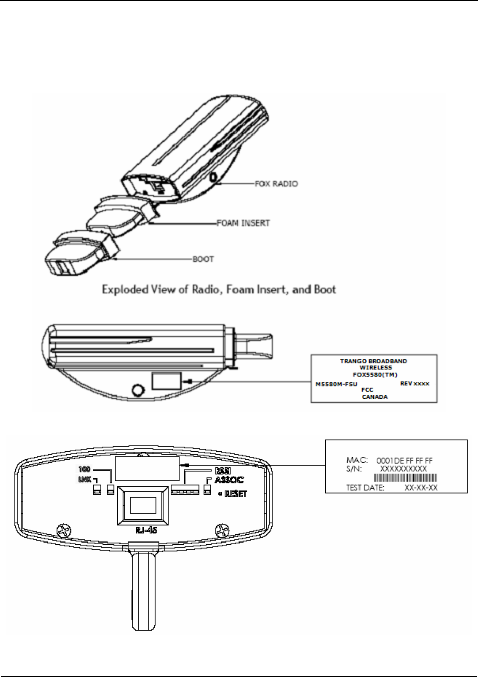
System Contents
Each kit consists of one radio with integrated antenna, one power-over-Ethernet (PoE) injector, one AC adapter,
One boot, and mounting hardware. A dual-polarized integrated antenna is located behind the radome of the
M5580M-FSU. (Dish Mounting Hardware not included with the unit)
Figure 1
Figure 2 ( NOT INCLUDED) Figure 3
Overview
Trango Broadband Wireless — M5580M-FSU (Atlas Fox) User Manual Revision 2 page 4
Location of Serial Number & MAC Address
The serial number and MAC address label can be found on the back of each radio. The serial number and MAC address
is also provided on the system information screen. (See figure 4 & 5 below)
Figure 4
Figure 5
Overview
Trango Broadband Wireless — M5580M-FSU (Atlas Fox) User Manual Revision 2 page 5
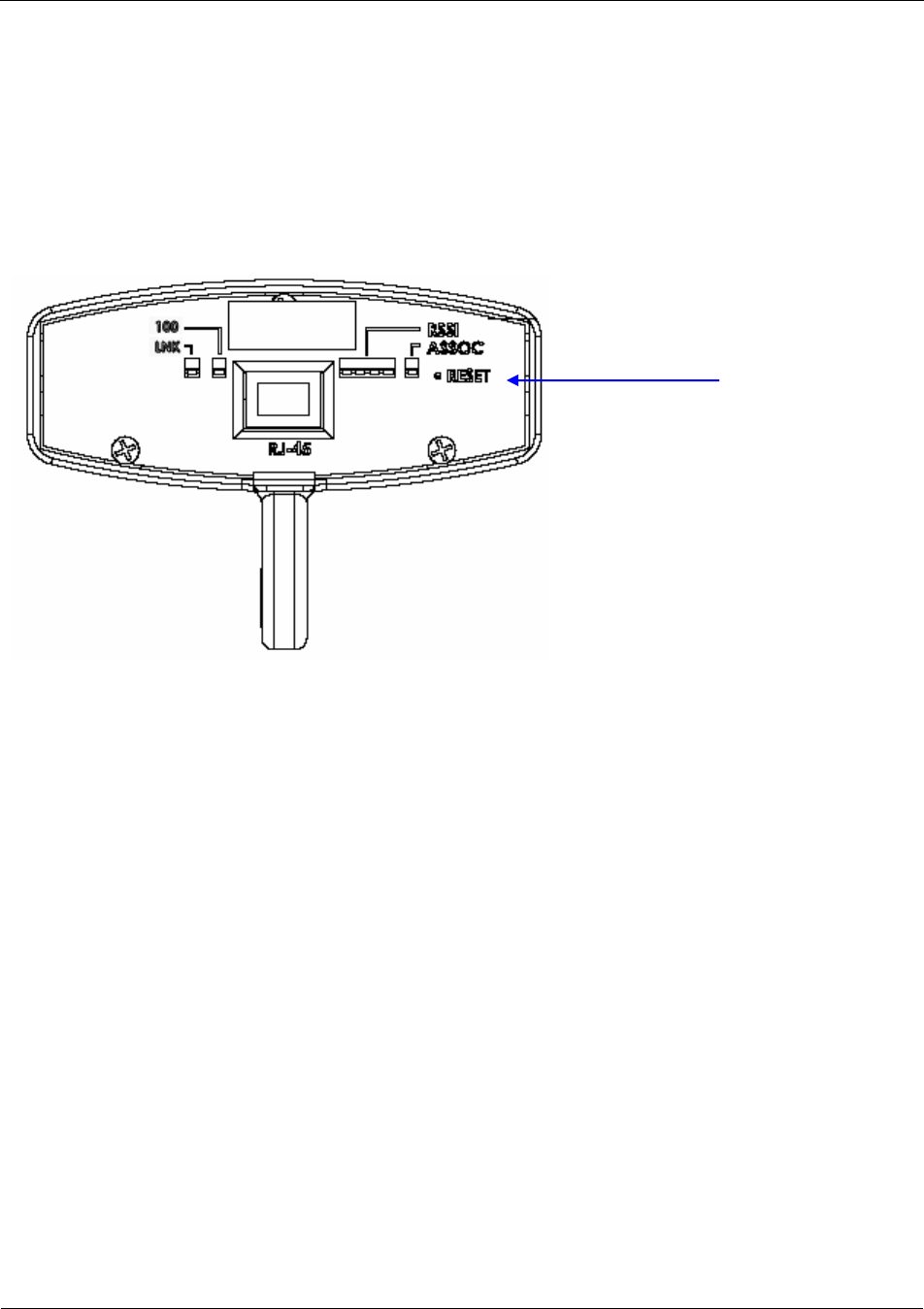
Location of RJ-45/LED Port
The RJ-45 connector, diagnostic LEDs, and reset button are located at the bottom of the radio. Functionality of the LEDs
is described later in this text. The reset button, resets all configuration settings (including IP address and password) back
to factory default. Hold the reset button down for 5 seconds (until amber lights flash) while unit is powered on.
Figure 6
Reset Button
Getting Started
Trango Broadband Wireless — M5580M-FSU (Atlas Fox) User Manual Revision 2 page 6
Chapter 2 Getting Started
It is recommended that you first provision and test your the radios on the bench before deploying them in the
field. This is a particularly useful exercise for the novice user.
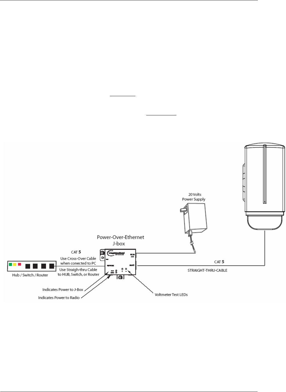
Connections and Power
• Connect a Cat-5 (straight through) Ethernet cable (we recommend shielded twisted pair) between the
ODU (out door unit) port of the J-box and the RJ-45 connector on the radio. Note that this cable will
carry power-over-Ethernet (PoE).
• If connecting to a COMPUTER, use a Cross-Over Ethernet cable from the NET port of the J-box to the
computer’s Ethernet port.
If connecting to a HUB, SWITCH, or ROUTER, use a Straight-Thru cable.
• Plug the AC adapter into an AC outlet.
Figure 7
Both green LEDs on the J-box should be lit, indicating power is present at the PoE box as well as at the radio.
The Radio’s Power LED may take several seconds before lighting. It will require approximately 45 seconds for
the radio to boot and be ready for configuration via the Ethernet port.
Note: If voltage falls below 16 volts, the power LED will go off but the Radio LED will stay on. The radio
can operate down to 10.5 volts.

Getting Started
Trango Broadband Wireless — M5580M-FSU (Atlas Fox) User Manual Revision 2 page 7
Configuration Tools
M5580M-FSU radios can be configured using either the Command Line Interface (CLI), or the Web Browser
(HTTP) interface. Although both methods are comprehensive and powerful, the CLI method provides slightly
more functionality.
This text covers configuration through the CLI. For HTTP configuration please see Chapter 4 on page 18.
Telnet
Open a command prompt (DOS) session on your PC. Next, open a Telnet session by typing:
telnet <ip address of radio>
Example:
C:>telnet 192.168.100.100
Note: All Trango radios are pre-configured at the factory with a default IP address of 192.168.100.100,
Subnet Mask 255.255.255.0, and Default Gateway 192.168.100.100.
Note: The M5580 can handle up to 4 telnet sessions.
You will be greeted with current hardware and firmware information and prompted for a password. Type in the
password and press enter. The factory default read/write password is trango.
Welcome to Trango Broadband Wireless, M5580M 2p0r8D06011801
Password:
Note: Type help for a listing of all CLI commands. Type help [<command>], for the syntax of a
particular command.
Note: If you cannot access the radio management functions via the Ethernet port, check all cable
connections and ensure that your PC is set up with a correct IP scheme.
Troubleshooting Ethernet Connections
If you cannot telnet into the radio or open an HTTP browser session, check your cable connections to
ensure proper use of cross-over vs. straight-through cable, and ensure your PC’s subnet is routable to the
radio’s IP address. You can also, try pressing and holding the reset button on the unit to ensure default IP
address and password.

Getting Started
Trango Broadband Wireless — M5580M-FSU (Atlas Fox) User Manual Revision 2 page 8
System Information (sysinfo) Page
To display system configuration and status information type the command sysinfo at prompt.
#> sysinfo
[Hardware Version] 5580
[MVC Version] 3893mvc_4p5_050913.arm
[Firmware Version] 2p0r8D06011801
[Device ID] 00 01 DE 00 04 47 [Base ID] 1 [AP ID] 1 [SU ID] 1
[System Up Time] 0 day(s) 00:22:51
[Opmode] off [Default Opmode] off [Opmode Start] 30 sec
[IP] 192.168.100.100 [Subnet Mask] 255.255.255.0 [Gateway] 192.168.100.1
[Httpd Port] 80 [Httpd Status] listen
[Telnetd Port] 23 [Telnetd Status] connected
[Telnet Client #1] 192.168.100.111,1093
[Telnet Client #2] 192.168.100.111,1092
[Telnet Client #3] 192.168.100.111,1088
[Telnet Client #4] 192.168.100.111,1087
[Tftpd] disabled
[RF Tx Power] 21 dBm
Channel Table: (MHz)
[Ch#01] 5736 [Ch#02] 5756 [Ch#03] 5776 [Ch#04] 5796 [Ch#05] 5816 [Ch#06] 5836
[Ch#07] 5736 [Ch#08] 5736 [Ch#09] 5736 [Ch#10] 5736 [Ch#11] 5736 [Ch#12] 5736
[Ch#13] 5736 [Ch#14] 5736 [Ch#15] 5736 [Ch#16] 5736 [Ch#17] 5736 [Ch#18] 5736
[Ch#19] 5736 [Ch#20] 5736 [Ch#21] 5736 [Ch#22] 5736 [Ch#23] 5736 [Ch#24] 5736
[Ch#25] 5736 [Ch#26] 5736 [Ch#27] 5736 [Ch#28] 5736 [Ch#29] 5736 [Ch#30] 5736
[Channel Scan Sequence] 5 v
[Active Channel] 5 v Disconnected
[Broadcast Packet] on [Auto Scan AP] on [TCP/IP for AP] off [TCP/IP for Local Et
h] off
[Remarks] Remarks
[ARQ] on
[RF Rx] 0 Kbps [RF Tx] 0 Kbps [Eth Rx] 3 Kbps [Eth Tx] 101 Kbps
[Eth Rx] 51,723 bytes [Eth Tx] 64,975 bytes
[RF Rx] 0 bytes [RF Tx] 0 bytes
Success.
#>
Note: Four open Telnet sessions indicated in bold within the sysinfo displayed above
For more information, see table #3 below.

Configuration
Trango Broadband Wireless — M5580M-FSU (Atlas Fox) User Manual Revision 2 page 9
Chapter 3 Configuration
Key Concepts
Prior to configuring the radios, it is important to understand several key concepts:
Access Point (AP) The AP is typically considered the primary radio within the link. It is
recommended to install the AP closest to the head-end of the network.
Subscriber Unit (SU) The SU is typically installed at the customer premise. The primary distinction
between the AP and SU is that when the radios are not associated, the AP will
transmit and the SU will listen until the wireless link is established.
Authentication Authentication is controlled by the AP via BASEID, SU ID and the MAC
address of each SU
Opmode Operation mode (on or off). The radio will only transmit while set to Opmode
ON.
Default Opmode Opmode (on or off) which the radio enters after reboot.
Note: if you telnet into a radio within 30 seconds after reboot, the radio will remain
in opmode OFF even if the default opmode is ON.
Essentials to Establish a Wireless Link
Configuration of the M5580M-FSU system is simple and at a minimum requires the following settings:
1. Set BASEID
2. Designate the SU ID.
3. Program SU ID, Mac and CIR/MIR settings on the AP.
4. Set AP and SU to same channel and antenna polarization
5. Set default Opmode to “ON”, the radio will automatically enter opmode on after a reboot.
6. Turn Opmode “ON”, both AP and SU.
If all of these parameters are met, and if the AP and SU are within range and properly aligned, the wireless
link will automatically establish itself and Ethernet traffic will begin to pass between the radios.
Access Point Basic Settings
For the Access Point basic configuration, see the M5830 User Manual

Configuration
Trango Broadband Wireless — M5580M-FSU (Atlas Fox) User Manual Revision 2 page 10
Subscriber Unit Basic Settings
Log into the SU. To receive a comprehensive snapshot of the system’s configuration info and status, type the
command sysinfo.
#> sysinfo
[Hardware Version] 5580
[MVC Version] 3893mvc_4p5_050913.arm
[Firmware Version] AFSU 2p0r8D06011801
[Device ID] 00 01 DE 00 04 3F [Base ID] 1 [AP ID] 1 [SU ID] 1
[System Up Time] 0 day(s) 00:00:39
[Opmode] off [Default Opmode] off [Opmode Start] 30 sec
[IP] 192.168.100.100 [Subnet Mask] 255.255.255.0 [Gateway] 192.168.100.1
[Httpd Port] 80 [Httpd Status] listen
[Telnetd Port] 23 [Telnetd Status] connected
[Telnet Client #1] 192.168.100.177,1637
[Tftpd] disabled
[RF Tx Power] 17 dBm
Channel Table: (MHz)
[Ch#01] 5736 [Ch#02] 5756 [Ch#03] 5776 [Ch#04] 5796 [Ch#05] 5816 [Ch#06] 5836
[Ch#07] 5736 [Ch#08] 5736 [Ch#09] 5736 [Ch#10] 5736 [Ch#11] 5736 [Ch#12] 5736
[Ch#13] 5736 [Ch#14] 5736 [Ch#15] 5736 [Ch#16] 5736 [Ch#17] 5736 [Ch#18] 5736
[Ch#19] 5736 [Ch#20] 5736 [Ch#21] 5736 [Ch#22] 5736 [Ch#23] 5736 [Ch#24] 5736
[Ch#25] 5736 [Ch#26] 5736 [Ch#27] 5736 [Ch#28] 5736 [Ch#29] 5736 [Ch#30] 5736
[Channel Scan Sequence] 5 v
[Active Channel] 5 v Disconnected
[Broadcast Packet] on [Auto Scan AP] on [TCP/IP for AP] off [TCP/IP for Local Eth] off
[Remarks] Remarks
[ARQ] on
[RF Rx] 0 Kbps [RF Tx] 0 Kbps [Eth Rx] 0 Kbps [Eth Tx] 0 Kbps
[Eth Rx] 1,629 bytes [Eth Tx] 2,812 bytes
[RF Rx] 0 bytes [RF Tx] 0 bytes
Success.
Many of these parameters can be changed by the user. A description of each of these changeable parameters,
along with the related command, is shown in table #3 below.
Table 2: Reference Table of Basic SU System Information
SU SYSTEM INFORMATION PARAMETERS AND RELATED COMMANDS
SU Parameter Description Related CLI Command
Device ID MAC Address of the SU N/A
Base ID Specifies the cell or cluster to set baseid <baseid>
which the SU belongs.
Example: #>Set baseid 10
SU ID Together with Base ID, it is
the unique identifier of this SU set suid <suid>
used in association. It is used Example:

Configuration
Trango Broadband Wireless — M5580M-FSU (Atlas Fox) User Manual Revision 2 page 11
to execute commands from the #>Set suid 3
AP to this specific SU.
AP ID Informational parameter that
shows to which AP the SU is Informational Parameter
associated. Please note that
AP ID is not used by the
system for SU authentication.
Opmode Current Opmode of radio. opmode su [< y>] / off
This sets the radio in Opmode “SU.” Or OFF
Default Opmode Determines the Opmode (“SU”
or “OFF”) of the radio after
reboot/power cycle. When the
parameter is set to “SU,” the
radio will progress into
Opmode “SU” automatically
fter reboot/power cycle.
set defaultopmode <su | off>
Example: #>set defaultopmode ap
IP
Subnet
Gateway
IP, Subnet, and Gateway
address of radio. ipconfig [<new ip> <new subnet mask> <new
gateway>]
Example: #>ipconfig 10.1.1.3 255.0.0.0 10.1.1.1
TFTPD TFTPD status (on or off).
TFTPD should be turned on to tftpd [<on | off>]
import file into radio (such as
new firmware). Default is off.
TFTPD will revert to off after
reboot/power cycle.
RF TX Power Current transmit power of the power set <dBm> (Range is 7..21)
SU not including antenna gain.
This is controlled during the
association process.
Channel Scan Sequence Shows the various channels (in
sequence) that the SU will freq scantable (displays scan table)
scan while searching for an freq scantable 5 v (sets Scan table to 5 v)
AP.
Active Channel Shows the channel used in the Information Parameter
current association, and
"Associated" or
"Disconnected" depending on
the association status.
Broadcast Packet Filter This software switch (0) sw 0 [<on | off>] (default is on)
enables/disables the blocking
of Ethernet control packets, Example:
except ICMP and ARP, to #>sw 0 on
reduce the amount of
unnecessary overhead
introduced to the wireless link.

Configuration
Trango Broadband Wireless — M5580M-FSU (Atlas Fox) User Manual Revision 2 page 12
AP Autoscan Software switch (1) is to sw 1 [<on | off>] (default is on)
turn AP autoscan on or off.
TCP/IP for AP Software switch (2), when on,
allows users at the AP side sw 2 [<on | off>] (default is on)
of the network to telnet or
HTTP into the SU.
HTTP services Software switch (5), when on,
allows local access via the
browser
sw 5 [<on|off>] (default is on)
TCP/IP for Local Ethernet This software switch (switch
6) when on, allows users on
the wired side of the SU to
telnet or HTTP into the SU.
sw 6 [<on | off>] (default is on)
Remarks User definable radio remarks [<remarks>]
information (i.e. customer Example:
name, address of installation, #>remarks 678 Oak Ave
and so on). Stores a
maximum of 28
characters can be stored.
Counters: These are averages of wired Informational Parameter
RF TX RF RX and wireless, transmit and
Eth TX Eth RX received, traffic in Kbps.
Establishing a Wireless Link
If the AP and SU are properly configured and in opmode “ON”, the two radios will automatically begin the
authentication process and become connected. To determine if the two radios are connected, type the
sysinfo command.
Example:
#> sysinfo
[Hardware Version] 5580
[MVC Version] 3893mvc_4p5_050913.arm
[Firmware Version] FSU 2p0r8D06011801
[Device ID] 00 01 DE 00 04 47 [Base ID] 1 [AP ID] 1 [SU ID] 1
[System Up Time] 0 day(s) 00:34:15
[Opmode] off [Default Opmode] off [Opmode Start] 30 sec
[IP] 192.168.100.100 [Subnet Mask] 255.255.255.0 [Gateway] 192.168.100.1
[Httpd Port] 80 [Httpd Status] listen
[Telnetd Port] 23 [Telnetd Status] connected
[Telnet Client #1] 192.168.100.111,1092
[Tftpd] disabled
[RF Tx Power] 21 dBm
Channel Table: (MHz)
[Ch#01] 5736 [Ch#02] 5756 [Ch#03] 5776 [Ch#04] 5796 [Ch#05] 5816 [Ch#06] 5836
[Ch#07] 5736 [Ch#08] 5736 [Ch#09] 5736 [Ch#10] 5736 [Ch#11] 5736 [Ch#12] 5736
[Ch#13] 5736 [Ch#14] 5736 [Ch#15] 5736 [Ch#16] 5736 [Ch#17] 5736 [Ch#18] 5736
[Ch#19] 5736 [Ch#20] 5736 [Ch#21] 5736 [Ch#22] 5736 [Ch#23] 5736 [Ch#24] 5736
[Ch#25] 5736 [Ch#26] 5736 [Ch#27] 5736 [Ch#28] 5736 [Ch#29] 5736 [Ch#30] 5736
[Channel Scan Sequence] 1 h
[Active Channel] 1 h Disconnected
[Broadcast Packet] on [Auto Scan AP] on [TCP/IP for AP] off [TCP/IP for Local Eth] off

Configuration
Trango Broadband Wireless — M5580M-FSU (Atlas Fox) User Manual Revision 2 page 13
[Remarks] Remarks
[ARQ] on
[RF Rx] 0 Kbps [RF Tx] 0 Kbps [Eth Rx] 3 Kbps [Eth Tx] 92 Kbps
[Eth Rx] 66,191 bytes [Eth Tx] 79,526 bytes
[RF Rx] 0 bytes [RF Tx] 0 bytes
Success.
#>
The [Active Channel] field indicates whether the AP and SU are connected or disconnected. If connected,
the AP and SU will automatically start passing Ethernet traffic over the wireless link.
Changing IP Address
Use the ipconfig command to change the radio’s ip address, subnet mask and gateway.
Syntax: ipconfig [<ip> <subnet> <gateway>]
Example:
#> ipconfig 192.168.100.101 255.255.255.0 192.168.100.1
New configuration: [ip] 192.168.100.101 [subnet mask] 255.255.255.0
[gateway] 19
2.168.100.1
save and activate ? (y/n) y
The new configuration will be saved and activated in 10 seconds.
Success.
#>
LEDs
LEDs are visible on the unit’s PCB between the reset button and the RJ-45 connector. The
function of each LED is described below:
LNK (green)
Green: On solid for an established 10BaseT or 100BaseT Ethernet Link.
100 (green)
Green: Solid if 100BaseT, Blinks only if there is activity (TX or RX) on the network when
a 100 MBit connection is established. Off if a 10BaseT connection is established or if
there is 10BaseT activity.
RSSI (4 Amber LEDs)
In all modes except “Survey”, the unit’s four yellow LEDs indicate the level of RF signal
being received from a VALID AP or SU as appropriate.
Yellow LED 1 : Begins blinking when RSSI is greater or equal to –90 dBm. On
continuously at –85 dBm. This is the Leftmost LED
Yellow LED 2 : Begins blinking when RSSI is greater or equal to –80 dBm. On
continuously at –75 dBm.
Yellow LED 3 : Begins blinking when RSSI is greater or equal to –70 dBm. On
continuously at –65 dBm.
Yellow LED 4 : Begins blinking when RSSI is greater or equal to –60 dBm. On
continuously at –55 dBm. This is the rightmost LED.

Configuration
Trango Broadband Wireless — M5580M-FSU (Atlas Fox) User Manual Revision 2 page 14
If no VALID AP or SU signal is detected the LEDs will not be on at all.
In addition, these 4 LEDs shall flash ON for 2 seconds, then OFF for 2 seconds to indicate
the 'factory reset' button has been activated and the reset successful.
ASSOC (association LED (green)):
The ASSOC led blinks at the following rates:
- Once every second when unit is powered on but opmode is OFF.
- Twice per second while in opmode ON and scanning for an AP or SU.
- Solid after unit is associated with the SU or AP.
Power Settings
Users may change the radio’s conducted output power using the power set commands or allow the
AP to control the output power. The following sample demonstrates how to manually set the
power.
(Power range from 7 – 21)
In this example, the user sets the power to 19dBm:
#> power set 19
Tx Power = 19 dBm
Success.
Using the HTTP Interface
Trango Broadband Wireless — M5580M-FSU (Atlas Fox) User Manual Revision 2 page 15
Chapter 4 Using the HTTP Interface
This section describes a few more basic concepts and how to establish a basic wireless link with the AP,
using the Browser (HTTP) Interface. This section addresses only the most basic steps in establishing a link in the
lab, or a bench-top environment. It is highly recommended that you read the Access 5830 Users Guide to gain
understanding of all important configuration parameters and procedures prior to deploying any wireless
equipment.
Configure Basic Parameters
Each SU must be set up with basic information to communicate with the AP. At a minimum the Base ID must
match the Base ID of the AP, the SU ID must match the SU ID in the AP.s SUDB, and the AP.s active channel
must exist in the SU.s AP Scan Sequence.
To set up the SU, complete the following steps:
1. Connect to the SU (see Chapter two “Getting Started”), and open the Configuration page.
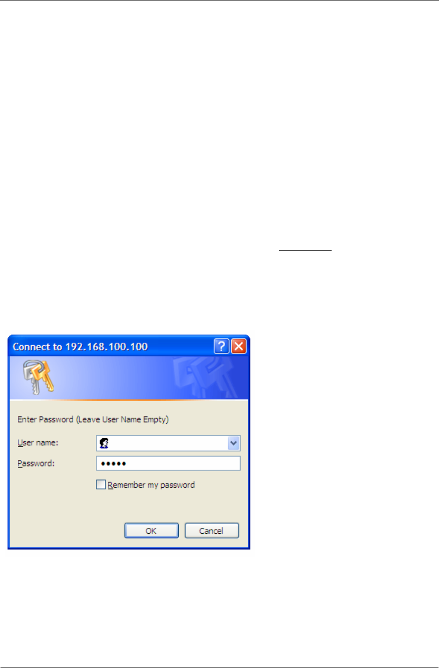
2. Open a browser session and type the IP address of the radio at the address bar of the browser. Default IP
address is 192.168.100.100.
3. Leave the User name field blank and enter read write or read only Password. Press or Click OK.
Default password is trango. After logging on, the system information screen will be displayed.
Figure 8
Using the HTTP Interface
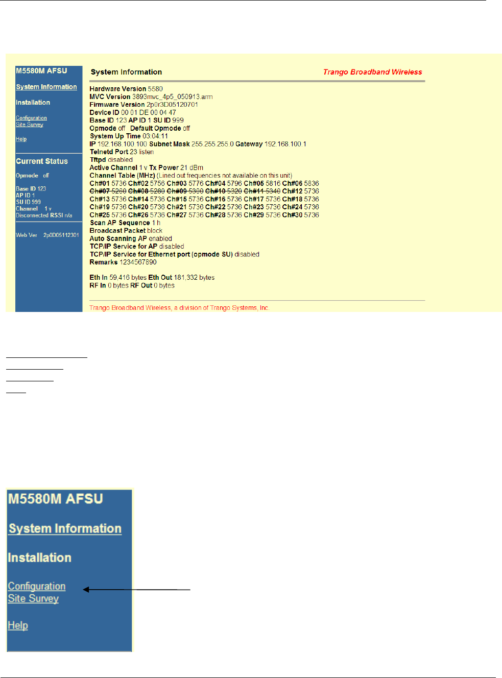
Trango Broadband Wireless — M5580M-FSU (Atlas Fox) User Manual Revision 2 page 16
Configure Basic Cont.
Figure 9
Navigation links are shown on the left side of the browser screen. Navigable links include:
System Information
Configuration
Site Survey
Help
The lower left portion of the screen shows the unit’s current opmode, connection, channel, and antenna status. The main
body of the System Information displays most of the key parameters. To view description of System Information entries
within the radio, click the Help link.
4. Click on Configuration
Figure 9

Using the HTTP Interface
Trango Broadband Wireless — M5580M-FSU (Atlas Fox) User Manual Revision 2 page 17
Configure Basic Cont.
5. Entered Base ID , AP ID (not required for establishing a link), and SU ID
(This settings must match those entered on the AP for this unit.)
Figure 10
6. Click on “Change IDs”
7. Configured Default Opmode to “SU” (This will ensure that your SU will establish a link when the power is cycle.)
8. Enter Channel(s) and Polarization(s) “Scan AP Sequence.”
(The SU will use these entries to look for an AP to link up to)
Figure 11
9. Click on “Save and Activate Settings”
10. Click on Activate Opmode.
Figure 12
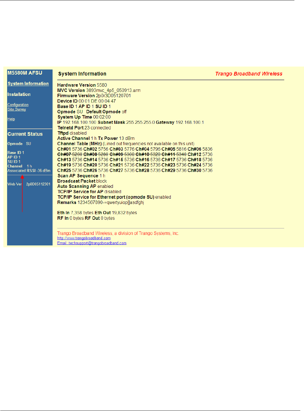
Using the HTTP Interface
Trango Broadband Wireless — M5580M-FSU (Atlas Fox) User Manual Revision 2 page 18
Configure Basic Continuo
If all settings are entered correctly, and if AP is within operating range, the SU will establish a wireless connection and
Ethernet traffic will begin to pass across the wireless link. The “Current Status” section can help you verify connection
status. The signal strength (RSSI) received from the AP is also provided under this section.
Figure 13

Deployment & Installation
Trango Broadband Wireless — M5580M-FSU (Atlas Fox) User Manual Revision 2 page 19
Chapter 5 Deployment & Installation
Once you are familiar with the basic operations of the M5580M-FSU, you are ready for deployment in the field. The
deployment process consists of the following steps:
• Site Selection
• Site survey at AP and SU sites
• AP installation
• SU installation and antenna alignment
• Link test
Site Selection
Proper site selection for your AP will help ensure a successful deployment. Site selection will depend on a wide variety of
factors, but from the radio’s performance standpoint, please consider the following:
• Path from AP to SU should provide unobstructed line-of-sight (LOS), thus it is advisable to place AP as high as
possible on a tall building or tower.
• Ethernet cable limit is 100 meters from Ethernet device (router, switch) to radio.
• Radios should never be deployed without proper grounding.
• Consider nearby sources of interference that could degrade the performance of the radio. Mount radios as far from
sources of interference as possible.
Site survey
The radios provide an on-board site survey tool to measure the average and peak noise levels on any given channel.
To use the survey tool, the radio must be in Opmode “OFF.” The survey can be performed for any specified amount of
time (in seconds), and for either the horizontal or vertical polarization.
Prior to performing the site survey, place the radio in the installation spot, and aim the radio in the desired direction.
After the specified period, the results of this command will provide you with a listing of each channel in the band, the
average signal received, and the maximum signal received during the survey period.
Example:
#> survey 10 h
Press 'q' to stop.
noise floor rssi by pkt
(peak / avg dBm) (peak / avg dBm)
Freq 5724 MHz -98 / -98 -99 / -99
Freq 5728 MHz -98 / -98 -99 / -99
Freq 5732 MHz -98 / -98 -99 / -99
Freq 5736 MHz Ch 1 -98 / -98 -99 / -99
Freq 5740 MHz -98 / -98 -99 / -99
Freq 5744 MHz -98 / -98 -99 / -99
Freq 5748 MHz -98 / -98 -99 / -99
Freq 5752 MHz -98 / -98 -99 / -99
Freq 5756 MHz Ch 2 -98 / -98 -99 / -99
Freq 5760 MHz -98 / -98 -99 / -99
Freq 5764 MHz -81 / -98 -99 / -99
Freq 5768 MHz -90 / -98 -99 / -99
Freq 5772 MHz -89 / -98 -99 / -99
Freq 5776 MHz Ch 3 -98 / -98 -99 / -99
Freq 5780 MHz -81 / -98 -99 / -99
Freq 5784 MHz -97 / -98 -99 / -99

Deployment & Installation
Trango Broadband Wireless — M5580M-FSU (Atlas Fox) User Manual Revision 2 page 20
Freq 5788 MHz -98 / -98 -99 / -99
Freq 5792 MHz -85 / -98 -99 / -99
Freq 5796 MHz Ch 4 -79 / -98 -99 / -99
(Survey Cont.)
Freq 5800 MHz -80 / -98 -99 / -99
Freq 5804 MHz -98 / -98 -99 / -99
Freq 5808 MHz -98 / -98 -99 / -99
Freq 5812 MHz -77 / -98 -99 / -99
Freq 5816 MHz Ch 5 -98 / -98 -99 / -99
Freq 5820 MHz -79 / -98 -99 / -99
Freq 5824 MHz -98 / -98 -99 / -99
Freq 5828 MHz -98 / -98 -99 / -99
Freq 5832 MHz -98 / -98 -99 / -99
Freq 5836 MHz Ch 6 -98 / -98 -99 / -99
Freq 5840 MHz -98 / -98 -99 / -99
Success.
#>
The results will display signal levels for each frequency in intervals of 4MHz for each channel. Select the channel with
lowest signal levels.
Note: Each Channel is 20MHz wide.
When selecting a channel, make sure to review 10MHz above and 10MHz below. As an example, Ch 5 covers
frequencies 5806 to 5826. This channel is not clear. Frequency 5812 has a noise level of -77dBm. This noise level will
interfered with your signal resulting in poor performance. Chanel 6 is a better choice.
Channel Planning
Based on the results of the site survey at each end of the link, choose a channel with the lowest noise floor. A clean spectrum is
essential for proper performance. It is recommended to maintain a 10dB fade margin or separation from the noise floor for
best performance.
RSSI Command and Antenna Alignment
Once the site survey is completed, you are ready to install your radios. Typically it is best to install the AP first.
To properly align the radios, use the built-in RSSI tool to achieve maximum signal strength.
1. Ensure SU is in Opmode “ON”
2. Connect to the SU.
3. Login and type the command rssi. As you read the RSSI, move the antenna in
the horizontal and vertical planes until the maximum RSSI reading is achieved
4. If it is not possible to receive an adequate RSSI reading, it may be necessary to
reorient the SU (up/down, left/right), to increase the output power of the AP, or
to move the SU to a location with better line-of-sight conditions to the AP.
5. Once you are satisfied with the RSSI reading, tighten down the SU in the
optimum position.

Deployment & Installation
Trango Broadband Wireless — M5580M-FSU (Atlas Fox) User Manual Revision 2 page 21
Example:
#> rssi
Press any key to stop.
0> AP -75 dB SU -75 dB Connected
1> AP -75 dB SU -75 dB Connected
2> AP -73 dB SU -73 dB Connected
3> AP -72 dB SU -71 dB Connected
4> AP -70 dB SU -70 dB Connected
5> AP -70 dB SU -69 dB Connected
6> AP -69 dB SU -70 dB Connected
7> AP -70 dB SU -70 dB Connected
8> AP -70 dB SU -70 dB Connected
9> AP -67 dB SU -68 dB Connected
10> AP -67 dB SU -67 dB Connected
Success.
Users can also view the RSSI LEDs on the bottom of the radio. See the figure14 and Table 3 below for more
information.
Figure 14 Table 3
RF Link Loopback Test (linktest command)
The linktest command provides over-the-air throughput and packet error rate (PER) statistics for the wireless link. This
command also provides RSSI at both the AP and SU. For more information and how to execute this command see the
M5830 user manual.
FOX Series Radio LED Guide
100 – This LED lights when connected to a 100BaseT
network. The LED remains unlit when
connected to a 10BaseT network
LINK – Indicates Ethernet Receive/Transmit activity
RSSI – Relative Signal Strength Indicator.
Lit LEDs Signal Strength
0 LED -80 dBm
1 LED -75 dBm
2 LED -70 dBm
3 LED -65 dBm
4 LED -60 dBm
ASSOC - This LED indicates one of four status:
1. Off – when there is no power at the radio
2. Blinks once every second – unit is powered on, but in
Opmode “OFF”
3. Blinks twice per second – unit is in Opmode “SU”,
and is scanning for an AP
4. Solid On – Unit is associated with an AP.
Deployment & Installation
Trango Broadband Wireless — M5580M-FSU (Atlas Fox) User Manual Revision 2 page 22
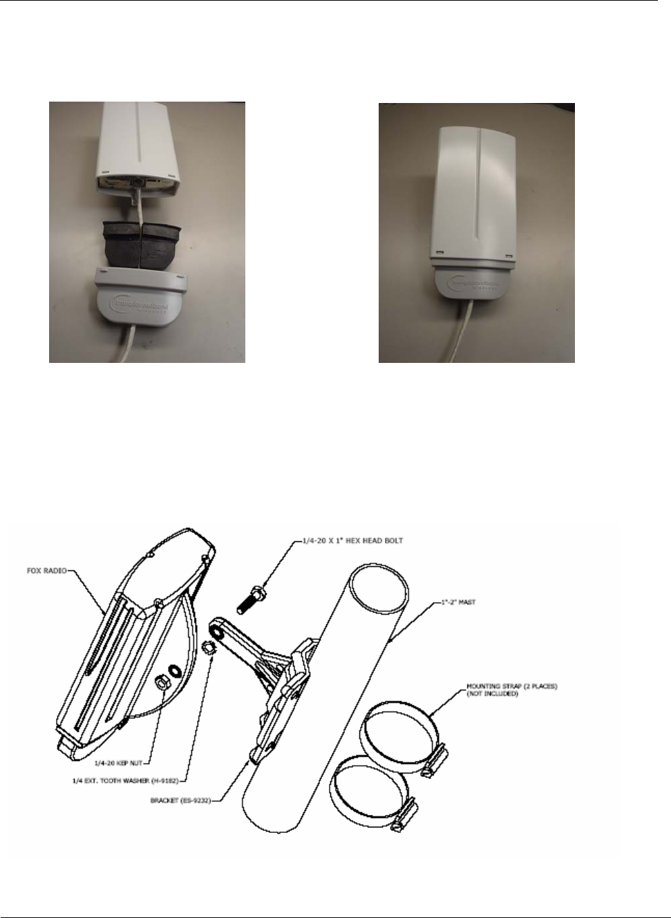
Strain relief and boot installation
Prior to deployment, insert a properly terminated Cat-5 Cable through Boot and the Foam strain relief. Connect the
Cable into the M5580M-FSU’s port opening. Last, clip the front end of the boot into the unit and then clip the back end
of the boot into to the unit, as shown in the photographs below.
Figure 15 Figure 16
Mounting Hardware
Radios are supplied with mounting hardware for pole and antenna dish installations. See figure 17 - 21 below for proper
use of the mounting hardware.
Figure 17
Figure 17: M5580M – FSU Series SU Pole Mount (1” – 2” Diameter)
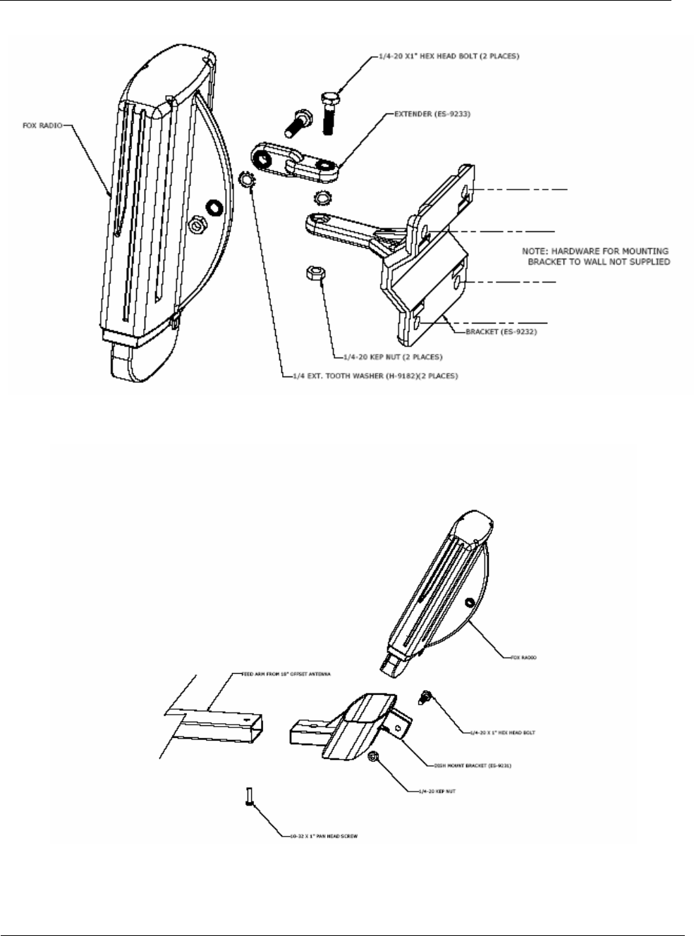
Deployment & Installation
Trango Broadband Wireless — M5580M-FSU (Atlas Fox) User Manual Revision 2 page 23
Figure 18: M5580M-FSU Series SU Wall Mount
Figure 19: Mounting M5580M-FSU with Mounting Cradle for AD5800-25 Reflector Dish
Deployment & Installation
Trango Broadband Wireless — M5580M-FSU (Atlas Fox) User Manual Revision 2 page 24
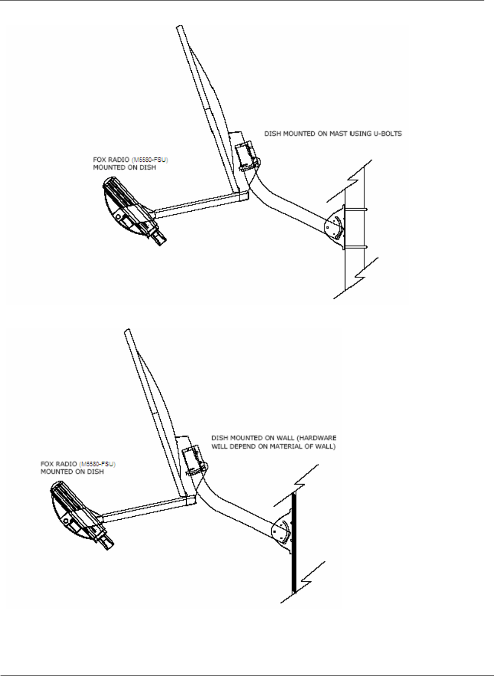
Figure 20: M5580M – FSU / AD5800 -25 Reflector Dish on Pole
Figure 21: M5580M-FSU / AD5800-25 Reflector Dish on Wall

Trango Broadband Wireless — M5580M-FSU (Atlas Fox) User Manual Revision 2 page 25
Chapter 6 Cabling and Weather Considerations
Shielded twisted pair Cat-5 cable is recommended for all installations. The shield within the Cat-5 cable does need to be
grounded. The casing is made out of plastic and mounting it on a pole will not ground the radio. It is important to consider
that most Cat-5 cable will deteriorate over time if exposed to the weather (especially direct sunlight). It is recommended that
installers place all Cat-5 cables inside conduit. Plastic conduit is sufficient. If metal conduit is used, it is not necessary to use
shielded Cat-5 cable.
Weatherizing
!
!
Important! Please note that the silicon strain relief has a small gap when the cable is
installed. This is normal .
It is important to provide strain relief and drip loop for STP Cat-5 cables. Do not mount the
radio upside down as water will enter the bottom of the radio and cause permanent damage
!
Important! The Power-over-Ethernet injector is not a weatherized device and must be
located either indoors or in a weather-protected cabinet.

Firmware Upgrade Procedure
Trango Broadband Wireless — M5580M-FSU (Atlas Fox) User Manual Revision 2 page 26
Chapter 7 SNMP
All current SUs support SNMP via the AP. All poll most be done through the AP. See the Access 5830 User Guide for
further information on SNMP.

Firmware Upgrade Procedure
Trango Broadband Wireless — M5580M-FSU (Atlas Fox) User Manual Revision 2 page 27
Chapter 8 Firmware Upgrade Procedure
Before beginning, make sure that you have adequate TCP access to the unit. When upgrading through the wireless,
ensure that your link is not experiencing any packet lost or packet corruption. If the link is experiencing packet lost or
corruption, we recommend doing the upgrade via the Ethernet port at SU side instead.
The following example uses MS windows operating system.
After downloading the correct firmware and properly extracting it to a folder on your C or local drive, execute the
following:
1. From a command or DOS prompt, Open a telnet session to the unit.
Example: C:>telnet 192.168.100.100
(This sample uses the default IP address, you must use the correct IP address of your SU.)
2. At the login enter your password. The default password is trango.
3. Enable the tftp demon with the tftpd command
Example: #>tftpd on
4. Open a second MS-DOS window, access the correct folder where the firmware files where extracted to.
Example: C:> cd Trango Firmware
C:\Trango Firmware>_
5. Using windows TFTP utility, upload the firmware to the radio.
Example: C:\Trango Firmware>tftp 192.168.100.100 put FSU58_2p0r3D05120701.s19
6. A “transfer success” will displayed. Return to the telnet session and verified the successful transfer of the file with the
tftpd command
Example: #> tftpd
[Tftpd] listen [File Name] FSU58_2P0r3D05120701.S19 [File Length] 564606 bytes
[File Checksum] 73
Success.
Note: After the upload, the radio will activate the firmware automatically
7. To verified if the upgrade was successful, run the ver command and validate the new version.
Example: #>ver
[Hardware Version] 5580
[MVC Version] 3893mvc_4p5_050913.arm
[Firmware Version] FSU 2p0r3D05120701
Success.

Appendix B Specifications
Trango Broadband Wireless — M5580M-FSU (Atlas Fox) User Manual Revision 2 page 28
Appendix B Command Set Summary
Command Description Remarks
Apsearch Search for near by APs.
arq [on|off] enable or disable ARQ default on
Bye Terminate or exit telnet/serial session
Exit Terminate or exit telnet /serial session
freq [<ch#> <antenna>] set or display channel settings default 1 h
freq scantable Displays current scan table
freq channeltable Displays current channel table
freq writescan <ch> <h/v> … Creates channel scan table
freq writechannel <ch#> <freq>… modify channel table, up to 30 channels Opmode off only
help [<command>] display commands and proper usage
ipconfig [<ip> <subnet> <gateway>] change ip configuration
<ip> = ip address
<subnet> = subnet mask
<gateway> = gateway ip address
default:
IP 192.168.100.100
SN 255.255.255.0
GW 192.168.100.100
log [<# of entries, 1..179>
log <sum> <# of entries, 1..179>
Logout Exit telnet session
opmode [off|su [y]] set or display opmode default off
password <ro|rw|upgrade> Change password
<ro> = for read-only
<rw> = for read-write
<upgrade> = for upgrading firmware
default trango
ping <ip address> Ping ip address
polar <h/v> Sets antenna polarization Default: h
power [<dBm>] set or display tx power <dBm> Default 21
pppoeonly <on/off> Set radio to allow pppoe traffic only Default off
Reboot reboot unit
remarks [<str>] remarks, up to 80 characters
reset [all|0..2] reset all parameters to factory defaults
reset 0 XXXX parameters only
reset 1 XXXX parameters only
Rssi display RSSI for AP / SU and association status Opmode on only
set apid <id> Sets AP ids Default: 1
set baseid <id> Sets unit base id (Numeric Characters only 0 – 9) up to
999 Default: 1
set suid <id> sets SUs id Default: 1
set httpport [<1…65534>]
set telnetport [<1…65534>]
ssrssi [ch, h/v>] Search for best signal on a channel while in opmode off
survey <time, sec> <h/v> Survey for a clean non-interfered channel
sw [<sw #> <on/off>] Sets switches on or off
Sysinfo Displays system current information
syslog [<0/1> | clear]
tftpd [on|off] enable or disable tftpd default = off
enable for firmware
upgrade
tm
ver Displays current firmware version, MVC and hardware
version

Appendix B Specifications
Trango Broadband Wireless — M5580M-FSU (Atlas Fox) User Manual Revision 2 page 29
Appendix A Specifications
All specifications apply to M5580M-FSU unless otherwise noted.
Data Parameters
Modulation Format
CCK
Certification/Compliance FCC Part 15.247, 15.407: ETSI/EN301 489-1 (7.2) (pending)
Receiver Sensibility –83 dBm (1600 byte packet) to –87 dBm (64 byte packet)
EIRP 29dBm (8dBi Internal Antenna
User Data Throughput 10Mbps
Format 10/100 BaseT 10/100 BaseT
Network Protocols All IEEE 802.3 / 802.3u compliant protocols
Configuration and Management Telnet, TFTP, HTTP, SNMP (via AP only)
Upstream/Downstream Throughput CIR/MIR (Control by the AP)
Physical Interfaces
Ethernet Speed (via RJ45 shielded) 10/100 BaseT, Auto-sensing
Ethernet Packet Up to 3600 byte long packets (supports VLAN/VPN pass through)
POWER PARAMETERS
Power Method Power-over-Ethernet (PoE). DC Voltage injected at PoE J-Box
Voltage input limits into PoE J-Box 10.5 VDC - 20 VDC, 20 VDC Nominal
Voltage input limits into Radio 10.5 VDC – 20 VDC
Standard Power Supply (included) 120 VAC to 20 VDC
PoE Cat-5 Max Cable length 100 meters on 24 AWG STP Cat-5 Cable
Current Draw/Power 600 mA max. (12 W), using 20V standard adapter
Environmental
Radio Enclosure All-weather, powder coated, aluminum case/back with UV stabilized ABS radome
Temperature Range -40° to 60° C (-40° to 140° F)
NEMA Rating NEMA 4
Radio Dimensions 14.5 in. x 14.5 in. x 3.75 in. (INT) / 6.5 in. x 6.5 in. x 1.5 in (EXT)
Radio Weight 1 Lbs. (45 Kg)
User Interfaces RJ45 (shielded)
