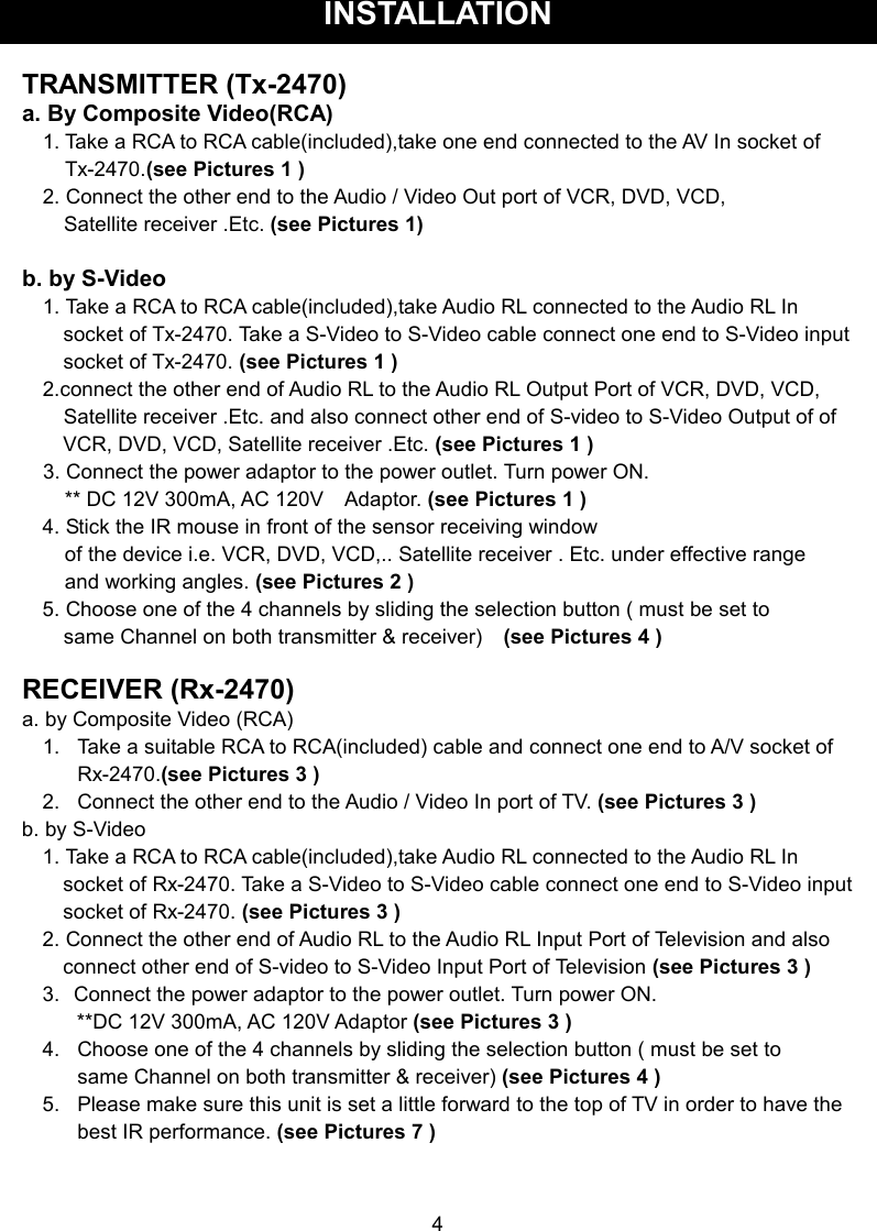
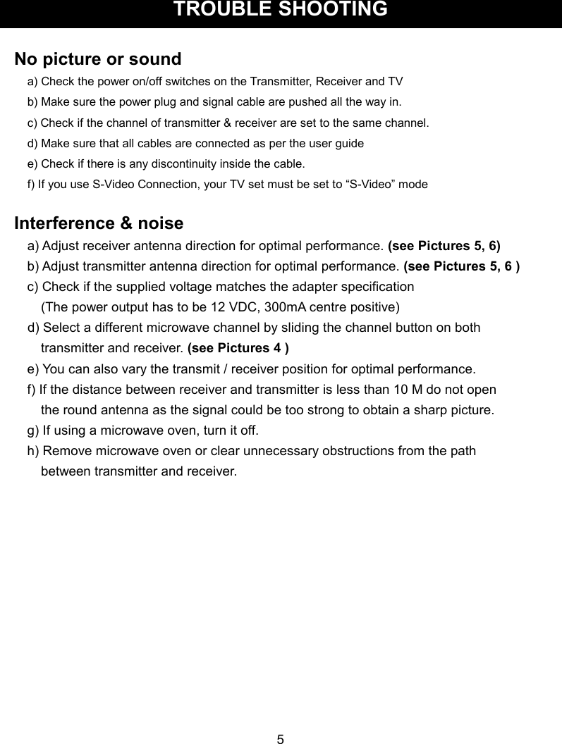
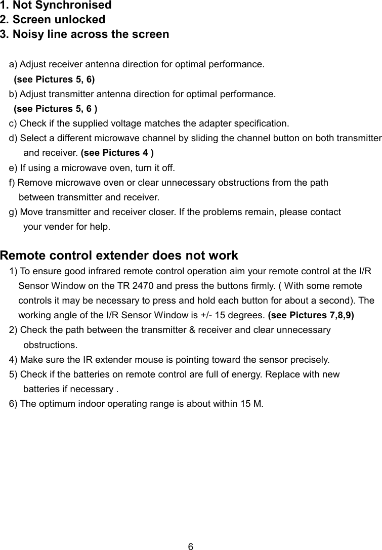
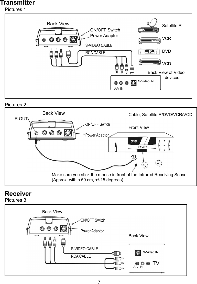
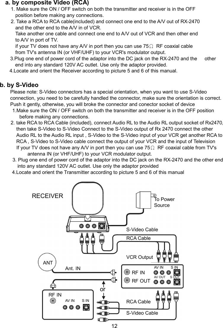
Trans Electric TR2470 2.4GHz Wireless Audio/Video Sender User Manual

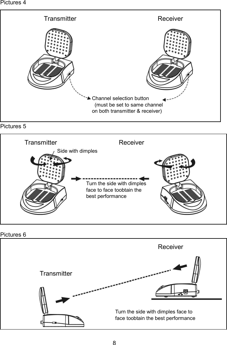
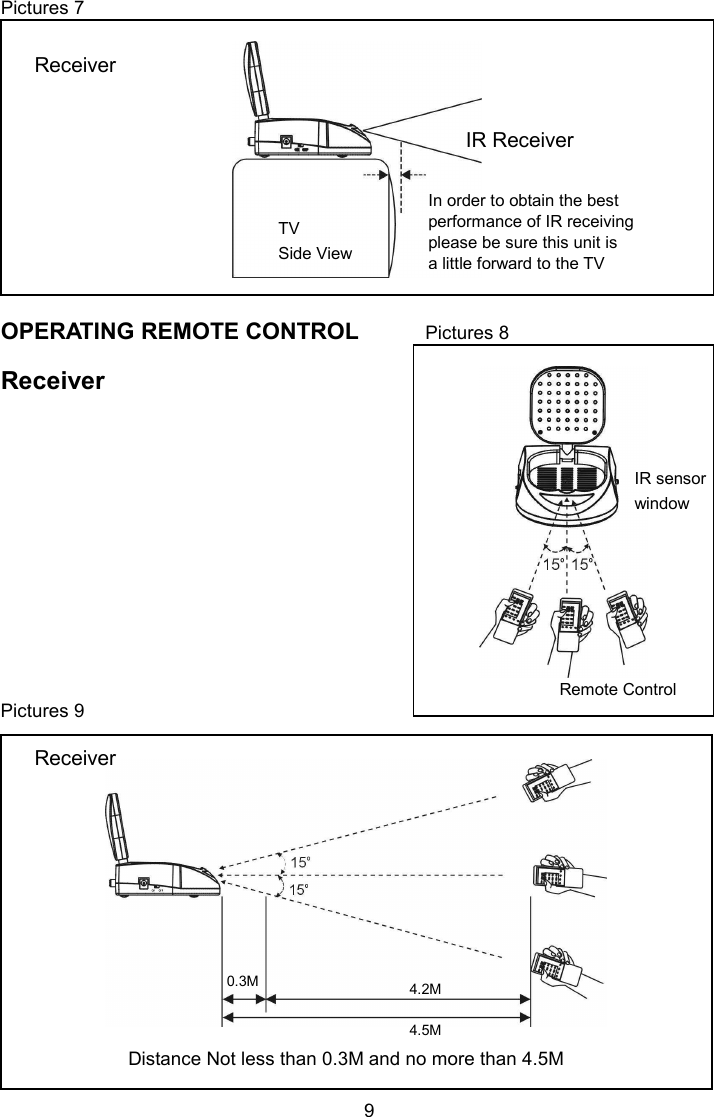
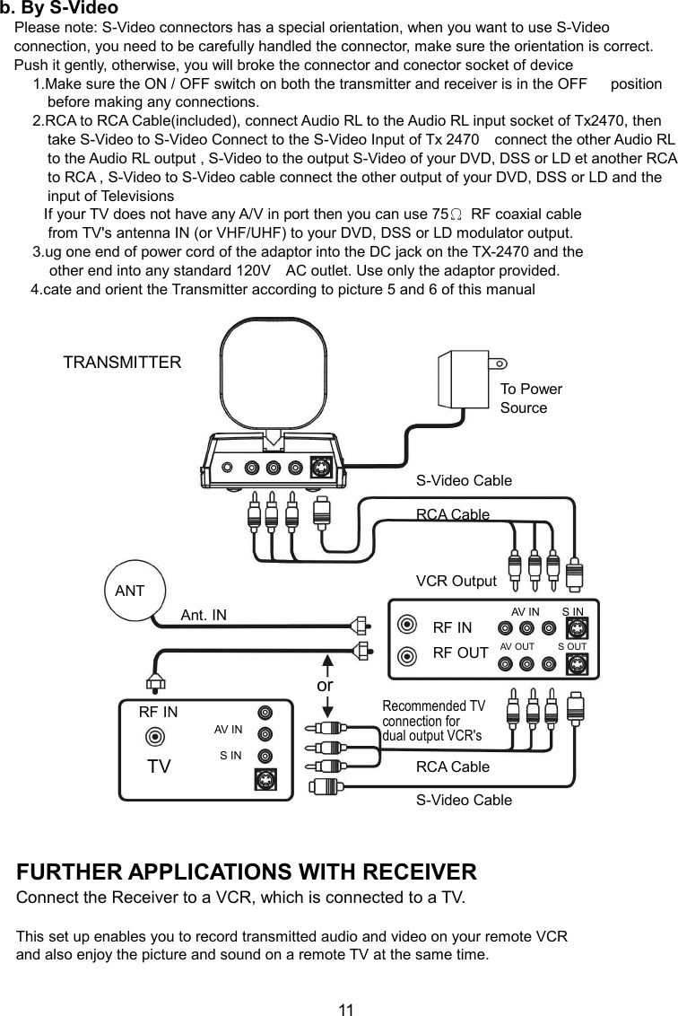
Trans Electric Co., Ltd. 2.4GHz Wireless Audio/Video Sender

User Manual

  2.4GHz Wireless, Audio/Video/S-Video Sender With Built-in Remote Control Extender MODEL: TR-2470   OWNERS MANUAL      Made in China
TABLE OF CONTENTS  ●  About the TR-2470      ...…....…...................……....…….......………......1 ● Location of controls and accessories        .……..…….……..………........2 ●  User Guide                    ...…............................……...….…………...........3 ●  Installation                    …........................….……….………..…...………..4 ●  Trouble Shooting            ...…....................….……….……….…….……5-6 ●  Referring Pictures        ..................…………….......……….….....….....7-9 ●  Further applications      .....................……….......………..…........... 10-12 ●  Caution                          ....................….……………...…………………...13 ●  Specification                ....................….………………..……….…………14  ABOUT THE TR-2470  The TR-2470 is a powerful wireless A/V/S-Video signal sender and receiver system which     can operate with satellite and cable receivers, camcorders, stereo systems,   televisions , laser disc players and VCRs, and provide superior reception at distances   of up to 250 feet (clear line of sight) from the transmitter.. And this system can support S-Video    This system can be used in many different ways:      ● Enables you to watch a movie on any television in your home without moving your             VCR or Laser Disc Player, and without the hassle of running wires.      ● Enables you to watch your favourite cable or satellite programs on any television in             your home.      ● Extends the listening enjoyment of your stereo receiver to any powered    speakers           in your home, even if they are not wired into your stereo system.      ● Enables you to use your camcorder with a remote television as a closed circuit           monitoring system; ideal for baby's room, or for security.     1
LOCATION OF CONTROLS The TR-2470 has been carefully engineered and manufactured to give you dependable   operation.    Read this manual before operating this unit to become familiar with its features   and obtain the performance that will bring you enjoyment for many years.   Please retain this manual for future reference.  Transmitter and              Transmitter and            Transmitter Back Receiver Side          Receiver Front                       Receiver Back            ●  Transmitter and Receiver      1. Channel Selector       2. 2.4 GHz Antenna 3. ON / OFF Switch     4. AC Adaptor Port         ● Transmitter 5.      Infrared Remote Output 6.      Audio L 7.      Audio R 8.      Video 9.      S-Video  2  ● Receiver 10.      Audio L 11.      Audio R 12.  Video 13.  S-Video ● Accessory 1.    DC 12V 300mA, AC 110V or 230V Adaptor x 1           (For Transmitter) 2.    DC 12V 300mA, AC 110V or 230V Adaptor x 1           (For Receiver) 3.   Infrared Extender Mouse x 1 4. A/V Cable x1  Remote Control Indicators   DC 12 V     AC 120V 300mA Infrared Extender
USER GUIDE   1. Make sure your input AC voltage conforms to the adaptor specifications.   ( Tolerance never more than 5%, such as 120 VAC +/- 10 VAC )       2. Only use the power adapter provided with the TR-2470. If you use your own   adaptor, make sure the power output is 12V DC, 300 mA centre positive.  3. With direct line-of-sight, the maximum range of A/V signal transmission can reach up to about 250 feet, and this distance would be shortened by obstacles or walls   placed between transmitter and receiver. (The optimum indoor range is under 25 M)      4. To ensure good infrared remote control operation aim your remote control at the I/R Sensor Window on the TR 2470 and press the buttons firmly. ( With some remote controls it may be necessary to press and hold each button for about a second). The working angle of the I/R Sensor Window is +/- 15 degrees. (see Pictures 7,8,)  5. The remote controller has to be used within the distance of ( from remote control   to receiver )not less than 0.3M and no more than 4.5M (working angle +/- 15 degrees).   (see Pictures 9)  6. Be sure the ON / OFF switch on both the transmitter and receiver is in the OFF position before making any connections.                   3
INSTALLATION  TRANSMITTER (Tx-2470) a. By Composite Video(RCA) 1. Take a RCA to RCA cable(included),take one end connected to the AV In socket of Tx-2470.(see Pictures 1 )   2. Connect the other end to the Audio / Video Out port of VCR, DVD, VCD,           Satellite receiver .Etc. (see Pictures 1)  b. by S-Video   1. Take a RCA to RCA cable(included),take Audio RL connected to the Audio RL In socket of Tx-2470. Take a S-Video to S-Video cable connect one end to S-Video input socket of Tx-2470. (see Pictures 1 ) 2.connect the other end of Audio RL to the Audio RL Output Port of VCR, DVD, VCD,       Satellite receiver .Etc. and also connect other end of S-video to S-Video Output of of VCR, DVD, VCD, Satellite receiver .Etc. (see Pictures 1 )     3. Connect the power adaptor to the power outlet. Turn power ON. ** DC 12V 300mA, AC 120V    Adaptor. (see Pictures 1 ) 4. Stick the IR mouse in front of the sensor receiving window   of the device i.e. VCR, DVD, VCD,.. Satellite receiver . Etc. under effective range   and working angles. (see Pictures 2 ) 5. Choose one of the 4 channels by sliding the selection button ( must be set to     same Channel on both transmitter & receiver)    (see Pictures 4 )  RECEIVER (Rx-2470) a. by Composite Video (RCA) 1.   Take a suitable RCA to RCA(included) cable and connect one end to A/V socket of             Rx-2470.(see Pictures 3 ) 2.   Connect the other end to the Audio / Video In port of TV. (see Pictures 3 ) b. by S-Video   1. Take a RCA to RCA cable(included),take Audio RL connected to the Audio RL In socket of Rx-2470. Take a S-Video to S-Video cable connect one end to S-Video input socket of Rx-2470. (see Pictures 3 ) 2. Connect the other end of Audio RL to the Audio RL Input Port of Television and also connect other end of S-video to S-Video Input Port of Television (see Pictures 3 ) 3.   Connect the power adaptor to the power outlet. Turn power ON.   **DC 12V 300mA, AC 120V Adaptor (see Pictures 3 ) 4.  Choose one of the 4 channels by sliding the selection button ( must be set to          same Channel on both transmitter & receiver) (see Pictures 4 ) 5.  Please make sure this unit is set a little forward to the top of TV in order to have the         best IR performance. (see Pictures 7 )    4
 TROUBLE SHOOTING    No picture or sound a) Check the power on/off switches on the Transmitter, Receiver and TV b) Make sure the power plug and signal cable are pushed all the way in. c) Check if the channel of transmitter & receiver are set to the same channel. d) Make sure that all cables are connected as per the user guide     e) Check if there is any discontinuity inside the cable. f) If you use S-Video Connection, your TV set must be set to “S-Video” mode  Interference & noise a) Adjust receiver antenna direction for optimal performance. (see Pictures 5, 6) b) Adjust transmitter antenna direction for optimal performance. (see Pictures 5, 6 ) c) Check if the supplied voltage matches the adapter specification         (The power output has to be 12 VDC, 300mA centre positive)     d) Select a different microwave channel by sliding the channel button on both           transmitter and receiver. (see Pictures 4 ) e) You can also vary the transmit / receiver position for optimal performance. f) If the distance between receiver and transmitter is less than 10 M do not open           the round antenna as the signal could be too strong to obtain a sharp picture. g) If using a microwave oven, turn it off. h) Remove microwave oven or clear unnecessary obstructions from the path         between transmitter and receiver.               5
1. Not Synchronised 2. Screen unlocked 3. Noisy line across the screen  a) Adjust receiver antenna direction for optimal performance.      (see Pictures 5, 6) b) Adjust transmitter antenna direction for optimal performance.    (see Pictures 5, 6 ) c) Check if the supplied voltage matches the adapter specification. d) Select a different microwave channel by sliding the channel button on both transmitter           and receiver. (see Pictures 4 ) e) If using a microwave oven, turn it off. f) Remove microwave oven or clear unnecessary obstructions from the path         between transmitter and receiver. g) Move transmitter and receiver closer. If the problems remain, please contact   your vender for help.  Remote control extender does not work 1) To ensure good infrared remote control operation aim your remote control at the I/R Sensor Window on the TR 2470 and press the buttons firmly. ( With some remote controls it may be necessary to press and hold each button for about a second). The working angle of the I/R Sensor Window is +/- 15 degrees. (see Pictures 7,8,9) 2) Check the path between the transmitter & receiver and clear unnecessary           obstructions. 4) Make sure the IR extender mouse is pointing toward the sensor precisely. 5) Check if the batteries on remote control are full of energy. Replace with new     batteries if necessary .   6) The optimum indoor operating range is about within 15 M.            6
Transmitter Pictures 1               Pictures 2              Receiver Pictures 3             7  Back View  Back View ON/OFF Switch Power Adaptor Satellite.R VCR DVD VCD Back View of Video  devices Make sure you stick the mouse in front of the Infrared Receiving Sensor (Approx. within 50 cm, +/-15 degrees) IR OUT Cable, Satellite.R/DVD/VCR/VCD  Front View   Back View A/V IN Back View TV ON/OFF Switch  Power Adaptor ON/OFF Switch  Power Adaptor S-Video IN A/V IN S-Video IN S-VIDEO CABLE RCA CABLE S-VIDEO CABLE RCA CABLE
Pictures 4                Pictures 5              Pictures 6              8 Transmitter                                                  Receiver  Channel selection button     (must be set to same channel  on both transmitter & receiver) Transmitter                                      Receiver  Side with dimples Turn the side with dimples  face to face toobtain the best performance                                                                                           Receiver Transmitter Turn the side with dimples face to face toobtain the best performance
Pictures 7                                                       OPERATING REMOTE CONTROL          Pictures 8  Receiver                                             Pictures 9                9    Remote Control Distance Not less than 0.3M and no more than 4.5M In order to obtain the best  performance of IR receiving please be sure this unit is  a little forward to the TV IR Receiver TV Side View IR sensor window 4.2M  4.5M 0.3M Receiver Receiver
FURTHER APPLICATIONS  FURTHER APPLICATIONS WITH VCR Connect the Transmitter to a VCR, which is connected to a TV.  a. by composite Video (RCA) 1. Make sure the ON / OFF switch on both the transmitter and receiver is in the OFF           position before making any connections. 2. Take a RCA to RCA cable and connect one end to the A/V in of TX-2470       and the other to A/V out of VCR.     Get another cable and connect one end to one of the A/V out ports of VCR and the other to A/V in of TV.       If your TV does not have any A/V in port then you can use 75Ω  RF coaxial cable     from TV's antenna IN (or VHF/UHF) to your VCR's modulator output. 3. Plug one end of power cord of the adaptor into the DC jack on the TX-2470 and the             other end into any standard 120V AC outlet. Use only the adaptor provided. 4. Locate and orient the Transmitter according to picture 5 and 6 of this manual.  b. By S-Video         Please note: S-Video connectors has a special orientation, when you want to use S-Video connection, you need to be carefully handled the connector, make sure the orientation is correct. Push it gently, otherwise, you will broke the connector and conector socket of device 1.Make sure the ON / OFF switch on both the transmitter and receiver is in the OFF      position before making any connections. 2.take RCA to RCA Cable(included), connect Audio RL to the Audio RL input socket of Tx2470, then take S-Video to S-Video Connect to the S-Video Input of Tx 2470    connect the other Audio RL to the Audio RL output of VCR, S-Video to the output S-Video of VCR get another RCA to RCA , S-Video to S-Video cable connect the other output of VCR and the input of Televisions   If your TV does not have any A/V in port then you can use 75Ω  RF coaxial cable     from TV's antenna IN (or VHF/UHF) to your VCR's modulator output. 3.Plug one end of power cord of the adaptor into the DC jack on the TX-2470 and the   other end into any standard 120V AC outlet. Use only the adaptor provided 4.Locate and orient the Transmitter according to picture 5 and 6 of this manual    FURTHER APPLICATIONS WITH DVD, DSS OR OTHER SATELLITE RECEIVER, OR LASER DISC PLAYER Connect the Transmitter to a DVD,LD, Satellite receiver, which is connected to a TV  a. by composite Video (RCA) 1. Make sure the ON / OFF switch on both the transmitter and receiver is in the OFF         position before making any connections. 2. Take a RCA to RCA cable(included)    and connect one end to the A/V out port of DVD,    DSS or LD and the other end to the A/V in of TX-2470.           Get another cable and connect to one of the A/V out of DDS, DVD, LD … and the other to A/V in of TV.         if your TV does not have any A/V in port then you can use 75Ω  RF coaxial cable         from TV's antenna IN (or VHF/UHF) to your DVD, DSS or LD modulator output. 3. Plug one end of power cord of the adaptor into the DC jack on the TX-2470 and the           other end into any standard 120V AC outlet. Use only the adaptor provided. 4. Locate and orient the Transmitter according to picture 5 and 6 of this manual. 10
b. By S-Video     Please note: S-Video connectors has a special orientation, when you want to use S-Video connection, you need to be carefully handled the connector, make sure the orientation is correct. Push it gently, otherwise, you will broke the connector and conector socket of device 1.Make sure the ON / OFF switch on both the transmitter and receiver is in the OFF      position before making any connections. 2.RCA to RCA Cable(included), connect Audio RL to the Audio RL input socket of Tx2470, then take S-Video to S-Video Connect to the S-Video Input of Tx 2470    connect the other Audio RL to the Audio RL output , S-Video to the output S-Video of your DVD, DSS or LD et another RCA to RCA , S-Video to S-Video cable connect the other output of your DVD, DSS or LD and the input of Televisions   If your TV does not have any A/V in port then you can use 75Ω  RF coaxial cable     from TV's antenna IN (or VHF/UHF) to your DVD, DSS or LD modulator output. 3.ug one end of power cord of the adaptor into the DC jack on the TX-2470 and the   other end into any standard 120V    AC outlet. Use only the adaptor provided. 4.cate and orient the Transmitter according to picture 5 and 6 of this manual                                 FURTHER APPLICATIONS WITH RECEIVER Connect the Receiver to a VCR, which is connected to a TV.  This set up enables you to record transmitted audio and video on your remote VCR   and also enjoy the picture and sound on a remote TV at the same time.   11  TRANSMITTER S-Video Cable RCA Cable Ant. IN Recommended TV connection for dual output VCR's TV To Power Source ANT VCR Output   RF IN RF OUT AV IN        S IN AV OUT          S OUT RCA Cable   S-Video Cable RF IN AV IN        S IN or
a. by composite Video (RCA) 1. Make sure the ON / OFF switch on both the transmitter and receiver is in the OFF           position before making any connections. 2. Take a RCA to RCA cable(included) and connect one end to the A/V out of RX-2470           and the other end to the A/V in of VCR.         Take another one cable and connect one end to A/V out of VCR and then other end         to A/V in port of TV.         if your TV does not have any A/V in port then you can use 75Ω  RF coaxial cable         from TV's antenna IN (or VHF/UHF) to your VCR's modulator output.                       3.Plug one end of power cord of the adaptor into the DC jack on the RX-2470 and the      other end into any standard 120V AC outlet. Use only the adaptor provided. 4.Locate and orient the Receiver according to picture 5 and 6 of this manual.  b. by S-Video Please note: S-Video connectors has a special orientation, when you want to use S-Video connection, you need to be carefully handled the connector, make sure the orientation is correct. Push it gently, otherwise, you will broke the connector and conector socket of device           1.Make sure the ON / OFF switch on both the transmitter and receiver is in the OFF position before making any connections. 2. take RCA to RCA Cable (included), connect Audio RL to the Audio RL output socket of Rx2470, then take S-Video to S-Video Connect to the S-Video output of Rx 2470 connect the other Audio RL to the Audio RL input , S-Video to the S-Video input of your VCR get another RCA to RCA , S-Video to S-Video cable connect the output of your VCR and the input of Television   If your TV does not have any A/V in port then you can use 75Ω  RF coaxial cable from TV's antenna IN (or VHF/UHF) to your VCR modulator output. 3. Plug one end of power cord of the adaptor into the DC jack on the RX-2470 and the other end into any standard 120V AC outlet. Use only the adaptor provided         4.Locate and orient the Transmitter according to picture 5 and 6 of this manual                           12   RECEIVER S-Video Cable RCA Cable  Ant. IN To Power Source ANT VCR Output   RF IN RF OUT AV IN        S IN AV IN        S IN   AV OUT      S OUT RCA Cable   S-Video Cable RF IN or
 CAUTION:  This equipment has been tested and found to comply with CE and FCC regulation.   These regulations are designed to provide reasonable protection against   interference in a residential installation. This equipment generates, uses and can radiate   radio frequency energy and, if not installed and used in accordance with this manual,   may cause interference to radio communications. However, there is no guarantee   that interference will not occur in a particular situation. If this equipment does cause   interference to radio or television reception, which can be determined by turning the   equipment off and on, the user is encouraged to try to correct the interference by   one or more of the following measures:  ● Reorient or relocate the receiving antenna  ● Increase the distance between the interfering equipment and the receiver  ● Connect the interfering equipment into an outlet on a circuit different from that         to which the receiver is connected.  ● Consult the dealer or an experienced radio/TV technician for help.     IMPORTANT SAFETY PRECAUTIONS   ● To prevent fire or shock hazard, do not submerge or expose these products to water  ● To avoid electric shock, do not open these units. The TR-2470 contains         no user serviceable parts. Doing so will void the warranty  ●  Use only the power adaptors provided with the TR-2470  ●  Do not overload wall outlets or extension cords.  ● If you are experiencing difficulty with this products, do not attempt to service       it yourself. Please call your reseller for assistance.  ● The changes or modifications not expressly approved by the party responsible for compliance could void the user’s authority to operate the equipment.    ● To comply with the FCC RF exposure compliance requirements, this device and its antenna must not be co-located or operating to conjunction with any other antenna   or transmitter.      13
SPECIFICATION  TRANSMITTER  Output level  0~10dBm    microvolts/meter @ 3 meters (complies with fcc) Operating frequency  2.4GHz - 2.4835GHz Modulation  FM (Video and Audio) Video input level  1.0 V p-p Audio input level  1 V rms S-Video Input Level  Y:1Vpp+-30%, C:288mV +-20% Video input impedance  75 ohm Audio input impedance  4.7K ohm Power Consumption  DC 12V@300mA Unit dimensions  12 x 10 x 4.3cm Unit weight  200g Effective operating range  Approx. 250feet (clear line of sight)  RECEIVER  Output level  1.0V p-p +/- 0.3V p-p (Video) 1Vrms (Audio) S-Video Output Level  Y:1Vpp+-30%, C:288mV +-20% Power Consumption  12V DC@300mA Unit dimensions  12 x 10 x 4.3cm Unit weight  200g  IR TRANSMITTER  Output level  0~10dBm Operating Frequency  433.92MHz +/-1MHz Modulation Type    AM Effective operating range  Approx. 100 feet(clear line of sight)  IR RECEIVER  Operating Frequency  433.92MHz+/-1MHz Sensitivity  <-80dBm    14

Navigation menu