TransCore 05531 LMS TRANSMITTER User Manual E4 SG
TransCore LMS TRANSMITTER E4 SG
USERS MANUAL

TransCore
3410 Midcourt Road, Suite 102
Carrollton, Texas 75006
April 2008
P/N 412066
Encompass™4/4800 Multiprotocol Reader
System Guide

Encompass 4/4800 Multiprotocol Reader System Guide
Information in this document is subject to change and does not represent a commitment on the part of
TC IP, Ltd.
©2008 TC IP, Ltd. All rights reserved. TRANSCORE and AMTECH and EGO are registered trademarks
and ENCOMPASS is a trademark of TC IP, Ltd., and are used under license. All other trademarks listed are
the property of their respective owners. Contents are subject to change. Printed in the U.S.A.
Products covered by this document are protected by one or more of the following U.S. patents 4,739,328;
4,782,345; 4,786,907; 4,816,839; 4,853,705; 4,864,158; 4,999,636; 5,030,807; 5,528,222; 5,550,547;
5,606,323; 5,673,037; 5,889,489; 5,912,632; 5,942,987; 6,097,347; 6,121,880; 6,275,157; 6,975,228; and
foreign equivalent patents. Other patents pending.
For further information, contact:
TransCore
3410 Midcourt Road, Suite 102
Carrollton, Texas 75006 USA
Phone: (214) 461-4031
Fax: (214) 461-6478
Technical Support
Phone: (800) 755-0378
Web: transcore.com/rfidsupport
For comments or questions about this document, e-mail tech.pubs@transcore.com.

WARNING TO USERS IN THE UNITED STATES
FEDERAL COMMUNICATIONS COMMISSION (FCC)
LOCATION AND MONITORING SERVICE STATEMENT
47 CFR §90.351
NOTE: The user is required to obtain a Part 90 site license from the FCC to operate this radio frequency
identification (RFID) device in the United States. See product label for FCC ID number. Access the FCC
Web site at www.fcc.gov/Forms/Form601/601.html for additional information concerning licensing
requirements.
NOTE: Users in all countries should check with the appropriate local authorities for licensing
requirements.
FCC RADIO FREQUENCY INTERFERENCE STATEMENT
47 CFR §15.105(a)
NOTE: This equipment has been tested and found to comply with the limits for a Class A digital device
pursuant to Part 15 of the FCC rules. These limits are designed to provide reasonable protection against
harmful interference when the equipment is operated in a commercial environment. This equipment
generates, uses, and can radiate RF energy and may cause harmful interference to radio communications if
not installed and used in accordance with the instruction manual. Operating this equipment in a residential
area is likely to cause harmful interference, in which case, depending on the laws in effect, the user may be
required to correct the interference at their own expense.
NO UNAUTHORIZED MODIFICATIONS
47 CFR §15.21
CAUTION: This equipment may not be modified, altered, or changed in any way without permission
from TransCore, LP. Unauthorized modification may void the equipment authorization from the FCC and
will void the TransCore warranty.
USE OF SHIELDED CABLES IS REQUIRED
47 CFR §15.27(a)
NOTE: Shielded cables must be used with this equipment to comply with FCC regulations.
TransCore, LP
USA

Encompass 4/4800 Multiprotocol Reader System Guide
Health Limits (865 to 875 MHz)
Within the United States, environmental guidelines regulating safe exposure lev-
els are issued by the Occupational Safety and Health Administration (OSHA).
Section 1910.97 of OSHA Safety and Health Standards 2206 legislates a maxi-
mum safe exposure limit of 10 milliwatts per square centimeter (mW/cm2) aver-
aged over 6 minutes at 865 MHz.
Although not binding, other organizations such as the American National Stan-
dards Institute (ANSI) have issued similar guidelines that are more restrictive than
the OSHA limits (ANSI C95.1). ANSI guidelines recommend a maximum safe
power density in mW/cm2 of:
Frequency (in MHz)
1500
Thus, the maximum permissible exposure for general population/uncontrolled
exposure at 865 MHz is 0.58 mW/cm2. The power limit is a six-minute average.
The RF power density generated by the Encompass™ 4/4800 Multiprotocol
Reader was calculated using a maximum antenna gain of 9.5 dBi, equivalent to
the antenna gain of the internal antenna.
Warning
At 2 W transmitted power and a distance of 19.7 inches (50 cm) from the reader,
the maximum power density calculated was less than 0.58 mW/cm2. Install the
reader at least 19.7 inches (50 cm) from the general public. Maintenance per-
sonnel must remain at least 9.1 inches (23 cm) from reader when system is oper-
ating.
The data confirms that the TransCore Encompass 4/4800 Multiprotocol Reader
effectively meets OSHA requirements and thus does not represent an operating
hazard to either the general public or maintenance personnel.

Encompass 4/4800 Multiprotocol Reader System Guide
Health Limits (902 to 928 MHz)
Within the United States, environmental guidelines regulating safe exposure levels are
issued by the Occupational Safety and Health Administration (OSHA).
Section 1910.97 of OSHA Safety and Health Standards 2206 legislates a maximum
safe exposure limit of 10 milliwatts per square centimeter (mW/cm2) averaged over 6
minutes at 902 MHz.
Although not binding, other organizations such as the American National Standards
Institute (ANSI) have issued similar guidelines that are more restrictive than the
OSHA limits (ANSI C95.1). ANSI guidelines recommend a maximum safe power
density in mW/cm2 of:
Frequency (in MHz)
1500
Thus, the maximum permissible exposure for general population/uncontrolled expo-
sure at 902 MHz is 0.60 mW/cm2. The power limit is a six-minute average.
The RF power density generated by the Encompass 4/4800 Multiprotocol Reader was
calculated using a maximum antenna gain of 9.5 dBi, equivalent to the antenna gain of
the internal antenna.
Warning
At 2 W transmitted power and a distance of 19.3 inches (49 cm) from the reader, the
maximum power density calculated was less than 0.60 mW/cm2. Install the reader at
least 19.3 inches (49 cm) from the general public. Maintenance personnel must
remain at least 8.66 inches (22 cm) from reader when system is operating.
The data confirms that the TransCore Encompass 4/4800 Multiprotocol Reader effec-
tively meets OSHA requirements and thus does not represent an operating hazard to
either the general public or maintenance personnel.

Encompass 4/4800 Multiprotocol Reader System Guide

Contents


vii
Contents
Health Limits (865 to 875 MHz) . . . . . . . . . . . . . . . . . . . . . . . . . . . . . . . . . . . . . . . . . . iv
Health Limits (902 to 928 MHz) . . . . . . . . . . . . . . . . . . . . . . . . . . . . . . . . . . . . . . . . . . . v
1 Introduction
Purpose. . . . . . . . . . . . . . . . . . . . . . . . . . . . . . . . . . . . . . . . . . . . . . . . . . . . . . . . . . . . 1-3
Audience. . . . . . . . . . . . . . . . . . . . . . . . . . . . . . . . . . . . . . . . . . . . . . . . . . . . . . . . . . . 1-3
System Guide Organization . . . . . . . . . . . . . . . . . . . . . . . . . . . . . . . . . . . . . . . . . . . 1-3
Typographical Conventions . . . . . . . . . . . . . . . . . . . . . . . . . . . . . . . . . . . . . . . . . . . 1-5
System Description . . . . . . . . . . . . . . . . . . . . . . . . . . . . . . . . . . . . . . . . . . . . . . . . . . 1-5
Reader. . . . . . . . . . . . . . . . . . . . . . . . . . . . . . . . . . . . . . . . . . . . . . . . . . . . . . . . . . . 1-6
Tags. . . . . . . . . . . . . . . . . . . . . . . . . . . . . . . . . . . . . . . . . . . . . . . . . . . . . . . . . . . . . 1-6
How It Works . . . . . . . . . . . . . . . . . . . . . . . . . . . . . . . . . . . . . . . . . . . . . . . . . . . . . . 1-6
Licensing Requirements . . . . . . . . . . . . . . . . . . . . . . . . . . . . . . . . . . . . . . . . . . . . . . 1-7
Technical Support . . . . . . . . . . . . . . . . . . . . . . . . . . . . . . . . . . . . . . . . . . . . . . . . . . . 1-7
2 Developing the Site Plan
Overview . . . . . . . . . . . . . . . . . . . . . . . . . . . . . . . . . . . . . . . . . . . . . . . . . . . . . . . . . . . 2-3
Reading of Mixed Population Tags . . . . . . . . . . . . . . . . . . . . . . . . . . . . . . . . . . . . . 2-3
Reader and Tag Alignment . . . . . . . . . . . . . . . . . . . . . . . . . . . . . . . . . . . . . . . . . . . . 2-4
Polarization . . . . . . . . . . . . . . . . . . . . . . . . . . . . . . . . . . . . . . . . . . . . . . . . . . . . . . . 2-5
Unobstructed Line of Sight . . . . . . . . . . . . . . . . . . . . . . . . . . . . . . . . . . . . . . . . . . . 2-6
Antenna Selection . . . . . . . . . . . . . . . . . . . . . . . . . . . . . . . . . . . . . . . . . . . . . . . . . . . 2-8
AA3100 Yagi (without radome) . . . . . . . . . . . . . . . . . . . . . . . . . . . . . . . . . . . . . . . . 2-8
AA3101 Yagi (with radome). . . . . . . . . . . . . . . . . . . . . . . . . . . . . . . . . . . . . . . . . . . 2-9
AA3110 Parapanel . . . . . . . . . . . . . . . . . . . . . . . . . . . . . . . . . . . . . . . . . . . . . . . . . 2-9
AA3140 PCB Log Periodic . . . . . . . . . . . . . . . . . . . . . . . . . . . . . . . . . . . . . . . . . . . 2-9
AA3152 Universal Toll Antenna. . . . . . . . . . . . . . . . . . . . . . . . . . . . . . . . . . . . . . . . 2-9
AA3153 Toll Antenna. . . . . . . . . . . . . . . . . . . . . . . . . . . . . . . . . . . . . . . . . . . . . . . 2-10
Antenna and Tag Alignment . . . . . . . . . . . . . . . . . . . . . . . . . . . . . . . . . . . . . . . . . . 2-10
Polarization . . . . . . . . . . . . . . . . . . . . . . . . . . . . . . . . . . . . . . . . . . . . . . . . . . . . . . 2-10
Unobstructed Line of Sight . . . . . . . . . . . . . . . . . . . . . . . . . . . . . . . . . . . . . . . . . . 2-11

Encompass 4/4800 Multiprotocol Reader System Guide
viii
Site Layout and Traffic Flow . . . . . . . . . . . . . . . . . . . . . . . . . . . . . . . . . . . . . . . . . . 2-12
The Encompass 4/4800 Multiprotocol Reader Read Zone . . . . . . . . . . . . . . . . . . 2-13
Other Encompass 4/4800 Multiprotocol Readers in the Area . . . . . . . . . . . . . . . . 2-13
Lane Configurations . . . . . . . . . . . . . . . . . . . . . . . . . . . . . . . . . . . . . . . . . . . . . . . 2-14
Gate with Center Island Configuration . . . . . . . . . . . . . . . . . . . . . . . . . . . . . . . 2-14
Parking Garage with Ticket Island Configuration . . . . . . . . . . . . . . . . . . . . . . . 2-15
Overhead Reader Installation Configuration. . . . . . . . . . . . . . . . . . . . . . . . . . . 2-16
Lane Configurations for Encompass 4/4800 Multiprotocol Readers Using an
External Antenna. . . . . . . . . . . . . . . . . . . . . . . . . . . . . . . . . . . . . . . . . . . . . . . . . . 2-17
Gate with Center Island Configuration . . . . . . . . . . . . . . . . . . . . . . . . . . . . . . . 2-17
Parking Garage with Ticket Island Configuration . . . . . . . . . . . . . . . . . . . . . . . 2-18
Overhead Reader Installation Configuration. . . . . . . . . . . . . . . . . . . . . . . . . . . 2-18
Reflection, Refraction, and Diffraction of RF Signals . . . . . . . . . . . . . . . . . . . . . . 2-19
Existing Interference . . . . . . . . . . . . . . . . . . . . . . . . . . . . . . . . . . . . . . . . . . . . . . . 2-20
Electrical and Communications Requirements. . . . . . . . . . . . . . . . . . . . . . . . . . . 2-20
Junction Box . . . . . . . . . . . . . . . . . . . . . . . . . . . . . . . . . . . . . . . . . . . . . . . . . . . . . 2-20
Power and Communications Cables . . . . . . . . . . . . . . . . . . . . . . . . . . . . . . . . . . . 2-20
Electrical Power . . . . . . . . . . . . . . . . . . . . . . . . . . . . . . . . . . . . . . . . . . . . . . . . 2-21
Power Extension . . . . . . . . . . . . . . . . . . . . . . . . . . . . . . . . . . . . . . . . . . . . . 2-21
Host Communications . . . . . . . . . . . . . . . . . . . . . . . . . . . . . . . . . . . . . . . . . . . . . . 2-23
RS–232 Interface . . . . . . . . . . . . . . . . . . . . . . . . . . . . . . . . . . . . . . . . . . . . . . . 2-23
RS–422 Interface . . . . . . . . . . . . . . . . . . . . . . . . . . . . . . . . . . . . . . . . . . . . . . . 2-23
Wiegand Interface. . . . . . . . . . . . . . . . . . . . . . . . . . . . . . . . . . . . . . . . . . . . . . . 2-24
Input/Output Circuits . . . . . . . . . . . . . . . . . . . . . . . . . . . . . . . . . . . . . . . . . . . . . . . 2-24
Antenna Interface . . . . . . . . . . . . . . . . . . . . . . . . . . . . . . . . . . . . . . . . . . . . . . . . . 2-24
3 Choosing, Installing, and Removing Tags
Compatible Tag Types. . . . . . . . . . . . . . . . . . . . . . . . . . . . . . . . . . . . . . . . . . . . . . . . 3-3
Reader and Tag Model Interoperability. . . . . . . . . . . . . . . . . . . . . . . . . . . . . . . . . . 3-3
TransCore’s eGo Tags . . . . . . . . . . . . . . . . . . . . . . . . . . . . . . . . . . . . . . . . . . . . . . 3-4
eGo Windshield Sticker Tag . . . . . . . . . . . . . . . . . . . . . . . . . . . . . . . . . . . . . . . . . . 3-4
eGo Plus Sticker Tag . . . . . . . . . . . . . . . . . . . . . . . . . . . . . . . . . . . . . . . . . . . . . . . 3-5
eGo License Plate Tag . . . . . . . . . . . . . . . . . . . . . . . . . . . . . . . . . . . . . . . . . . . . . . 3-5
Intellitag Data Format . . . . . . . . . . . . . . . . . . . . . . . . . . . . . . . . . . . . . . . . . . . . . . . 3-6
Installing eGo Windshield Sticker Tags. . . . . . . . . . . . . . . . . . . . . . . . . . . . . . . . . . 3-6
Required Materials . . . . . . . . . . . . . . . . . . . . . . . . . . . . . . . . . . . . . . . . . . . . . . . . . 3-6
Positioning eGo Windshield Sticker Tags . . . . . . . . . . . . . . . . . . . . . . . . . . . . . . . . 3-7
Mirror Post Attached Low On Windshield. . . . . . . . . . . . . . . . . . . . . . . . . . . . . . 3-7
Mirror Post Attached High on Windshield. . . . . . . . . . . . . . . . . . . . . . . . . . . . . . 3-7
Mirror Post Attached to Headliner. . . . . . . . . . . . . . . . . . . . . . . . . . . . . . . . . . . . 3-8
eGo Windshield Sticker Tag Installation Procedures . . . . . . . . . . . . . . . . . . . . . . . 3-8
Removing eGo Windshield Sticker Tags . . . . . . . . . . . . . . . . . . . . . . . . . . . . . . . . . 3-9

Contents
ix
Installing eGo License Plate Tags . . . . . . . . . . . . . . . . . . . . . . . . . . . . . . . . . . . . . . 3-9
Required Materials . . . . . . . . . . . . . . . . . . . . . . . . . . . . . . . . . . . . . . . . . . . . . . . . . 3-9
Positioning eGo License Plate Tags . . . . . . . . . . . . . . . . . . . . . . . . . . . . . . . . . . . 3-10
eGo License Plate Tag Installation Procedures . . . . . . . . . . . . . . . . . . . . . . . . . . 3-11
Installing Interior ATA Tags . . . . . . . . . . . . . . . . . . . . . . . . . . . . . . . . . . . . . . . . . . 3-13
Required Materials . . . . . . . . . . . . . . . . . . . . . . . . . . . . . . . . . . . . . . . . . . . . . . . . 3-13
Positioning ATA Tags . . . . . . . . . . . . . . . . . . . . . . . . . . . . . . . . . . . . . . . . . . . . . . 3-13
Interior Driver’s or Passenger’s Side . . . . . . . . . . . . . . . . . . . . . . . . . . . . . . . . 3-13
Interior Center Windshield . . . . . . . . . . . . . . . . . . . . . . . . . . . . . . . . . . . . . . . . 3-14
ATA Interior Tag Installation Procedures. . . . . . . . . . . . . . . . . . . . . . . . . . . . . . . . 3-14
Removing Interior ATA Tags. . . . . . . . . . . . . . . . . . . . . . . . . . . . . . . . . . . . . . . . . . 3-15
Installing ATA License Plate Tags . . . . . . . . . . . . . . . . . . . . . . . . . . . . . . . . . . . . . 3-15
Required Materials . . . . . . . . . . . . . . . . . . . . . . . . . . . . . . . . . . . . . . . . . . . . . . . . 3-16
Positioning ATA License Plate Tags . . . . . . . . . . . . . . . . . . . . . . . . . . . . . . . . . . . 3-16
ATA License Plate Tag Installation Procedures . . . . . . . . . . . . . . . . . . . . . . . . . . 3-17
Types of Bumpers . . . . . . . . . . . . . . . . . . . . . . . . . . . . . . . . . . . . . . . . . . . . . . . . . 3-19
Alternate Mounting Locations . . . . . . . . . . . . . . . . . . . . . . . . . . . . . . . . . . . . . . . . 3-19
Required Materials . . . . . . . . . . . . . . . . . . . . . . . . . . . . . . . . . . . . . . . . . . . . . . . . 3-19
Installation Procedures Using Tape. . . . . . . . . . . . . . . . . . . . . . . . . . . . . . . . . . . . 3-20
Installation Procedures Using Blind Rivets . . . . . . . . . . . . . . . . . . . . . . . . . . . . . . 3-20
Removing Exterior Tags . . . . . . . . . . . . . . . . . . . . . . . . . . . . . . . . . . . . . . . . . . . . . 3-20
4 Installing the Encompass 4/4800 Multiprotocol Reader
Installation Process . . . . . . . . . . . . . . . . . . . . . . . . . . . . . . . . . . . . . . . . . . . . . . . . . . 4-3
Materials Supplied by TransCore . . . . . . . . . . . . . . . . . . . . . . . . . . . . . . . . . . . . . . 4-3
Contents of Shipping Carton. . . . . . . . . . . . . . . . . . . . . . . . . . . . . . . . . . . . . . . . 4-3
Installation Accessory Options . . . . . . . . . . . . . . . . . . . . . . . . . . . . . . . . . . . . . . 4-4
Additional Materials Needed for Testing . . . . . . . . . . . . . . . . . . . . . . . . . . . . . . . . . 4-4
Pre-installation Testing of the Encompass 4/4800 Multiprotocol Reader. . . . . . . 4-5
Testing the Encompass 4/4800 Multiprotocol Reader Using an Audible
Circuit Tester............................................................................................................4-5
Connecting the Antenna . . . . . . . . . . . . . . . . . . . . . . . . . . . . . . . . . . . . . . . . . . . . . 4-6
Connecting the AC Power Supply . . . . . . . . . . . . . . . . . . . . . . . . . . . . . . . . . . . . . . 4-6
Connecting the DC Power Supply. . . . . . . . . . . . . . . . . . . . . . . . . . . . . . . . . . . . . . 4-7
Connecting Communications for Bench Testing . . . . . . . . . . . . . . . . . . . . . . . . . . . 4-8
Required Materials . . . . . . . . . . . . . . . . . . . . . . . . . . . . . . . . . . . . . . . . . . . . . . . 4-8
Connecting for Bench Testing with RS–232 Interface . . . . . . . . . . . . . . . . . . . . 4-8
Connecting the Encompass 4/4800 Multiprotocol Reader
Colored-Wire Pair Cable . . . . . . . . . . . . . . . . . . . . . . . . . . . . . . . . . . . . . . . 4-10
Connecting for Bench Testing with RS–422 Interface . . . . . . . . . . . . . . . . . . . 4-11

Encompass 4/4800 Multiprotocol Reader System Guide
x
Connecting the Encompass 4/4800 Multiprotocol Reader
Colored-Wire Pair Cable for Bench Testing with RS–422 Interface. . . . . . . 4-11
Bench Testing the Encompass 4/4800 Multiprotocol Reader Before Installation . 4-12
Mounting the Encompass 4/4800 Multiprotocol Reader on Round Pole
or Flat Surface . . . . . . . . . . . . . . . . . . . . . . . . . . . . . . . . . . . . . . . . . . . . . . . . . . . . . 4-14
Mounting the Encompass 4/4800 Multiprotocol Reader on a Round Pole . . . . . . 4-14
Required Materials . . . . . . . . . . . . . . . . . . . . . . . . . . . . . . . . . . . . . . . . . . . . . . 4-14
Procedures . . . . . . . . . . . . . . . . . . . . . . . . . . . . . . . . . . . . . . . . . . . . . . . . . . . . 4-14
Mounting the Encompass 4/4800 Multiprotocol Reader to a Wall or Flat Surface 4-18
Required Materials . . . . . . . . . . . . . . . . . . . . . . . . . . . . . . . . . . . . . . . . . . . . . . 4-18
Procedures . . . . . . . . . . . . . . . . . . . . . . . . . . . . . . . . . . . . . . . . . . . . . . . . . . . . 4-18
Mounting the Antenna . . . . . . . . . . . . . . . . . . . . . . . . . . . . . . . . . . . . . . . . . . . . . . . 4-22
Mounting the Antenna Curb-Side . . . . . . . . . . . . . . . . . . . . . . . . . . . . . . . . . . . . . 4-22
Procedures . . . . . . . . . . . . . . . . . . . . . . . . . . . . . . . . . . . . . . . . . . . . . . . . . . . . 4-22
Mounting the Antenna Overhead . . . . . . . . . . . . . . . . . . . . . . . . . . . . . . . . . . . . . 4-23
Procedures . . . . . . . . . . . . . . . . . . . . . . . . . . . . . . . . . . . . . . . . . . . . . . . . . . . . 4-23
Connecting the Power Supply. . . . . . . . . . . . . . . . . . . . . . . . . . . . . . . . . . . . . . . . 4-24
Connecting Communications . . . . . . . . . . . . . . . . . . . . . . . . . . . . . . . . . . . . . . . . . 4-25
Required Materials . . . . . . . . . . . . . . . . . . . . . . . . . . . . . . . . . . . . . . . . . . . . . . . . 4-25
Connecting the Encompass 4/4800 Multiprotocol Reader to the PC . . . . . . . . . . 4-25
RS–232 Interface . . . . . . . . . . . . . . . . . . . . . . . . . . . . . . . . . . . . . . . . . . . . . . . 4-25
Connecting the Encompass 4/4800 Multiprotocol Reader
Colored-Wire Pair Cable . . . . . . . . . . . . . . . . . . . . . . . . . . . . . . . . . . . . . . . 4-26
RS–422 Interface . . . . . . . . . . . . . . . . . . . . . . . . . . . . . . . . . . . . . . . . . . . . . . . 4-27
Wiegand Interface. . . . . . . . . . . . . . . . . . . . . . . . . . . . . . . . . . . . . . . . . . . . . . . 4-28
Connecting Sense Input and Sense Output Circuits . . . . . . . . . . . . . . . . . . . . . . 4-28
Sense Input Circuits . . . . . . . . . . . . . . . . . . . . . . . . . . . . . . . . . . . . . . . . . . . . . . . 4-29
Sense Output Circuits . . . . . . . . . . . . . . . . . . . . . . . . . . . . . . . . . . . . . . . . . . . . . . 4-29
Marking the Read Zone . . . . . . . . . . . . . . . . . . . . . . . . . . . . . . . . . . . . . . . . . . . . . . 4-32
Required Materials . . . . . . . . . . . . . . . . . . . . . . . . . . . . . . . . . . . . . . . . . . . . . . . . 4-32
Procedures . . . . . . . . . . . . . . . . . . . . . . . . . . . . . . . . . . . . . . . . . . . . . . . . . . . . . . 4-32
5 General Software Information
Command Entry Conventions. . . . . . . . . . . . . . . . . . . . . . . . . . . . . . . . . . . . . . . . . . 5-3
Command Response Conventions. . . . . . . . . . . . . . . . . . . . . . . . . . . . . . . . . . . . . . 5-4
Operating Parameters . . . . . . . . . . . . . . . . . . . . . . . . . . . . . . . . . . . . . . . . . . . . . . . . 5-5
Power Fail . . . . . . . . . . . . . . . . . . . . . . . . . . . . . . . . . . . . . . . . . . . . . . . . . . . . . . . . . . 5-5
Program Download . . . . . . . . . . . . . . . . . . . . . . . . . . . . . . . . . . . . . . . . . . . . . . . . . . 5-5
Download Considerations . . . . . . . . . . . . . . . . . . . . . . . . . . . . . . . . . . . . . . . . . . . . 5-5
Download Procedures. . . . . . . . . . . . . . . . . . . . . . . . . . . . . . . . . . . . . . . . . . . . . . . 5-6

Contents
xi
Startup. . . . . . . . . . . . . . . . . . . . . . . . . . . . . . . . . . . . . . . . . . . . . . . . . . . . . . . . . . . . . 5-6
Sign-On Message . . . . . . . . . . . . . . . . . . . . . . . . . . . . . . . . . . . . . . . . . . . . . . . . . . 5-6
Boot Failure Message . . . . . . . . . . . . . . . . . . . . . . . . . . . . . . . . . . . . . . . . . . . . . . . 5-6
Tag/Message Buffer. . . . . . . . . . . . . . . . . . . . . . . . . . . . . . . . . . . . . . . . . . . . . . . . . . 5-7
6 Communications Protocols
Introduction . . . . . . . . . . . . . . . . . . . . . . . . . . . . . . . . . . . . . . . . . . . . . . . . . . . . . . . . 6-3
Basic Protocol . . . . . . . . . . . . . . . . . . . . . . . . . . . . . . . . . . . . . . . . . . . . . . . . . . . . . . 6-4
Error Correcting Protocol . . . . . . . . . . . . . . . . . . . . . . . . . . . . . . . . . . . . . . . . . . . . . 6-4
Basic Protocol and ECP Format. . . . . . . . . . . . . . . . . . . . . . . . . . . . . . . . . . . . . . . . 6-5
Reader Transmissions. . . . . . . . . . . . . . . . . . . . . . . . . . . . . . . . . . . . . . . . . . . . . . . 6-5
ECP Host ACK/NAK Response. . . . . . . . . . . . . . . . . . . . . . . . . . . . . . . . . . . . . . . . 6-6
Switch to Command Mode Request . . . . . . . . . . . . . . . . . . . . . . . . . . . . . . . . . . . . 6-7
Host Transmission. . . . . . . . . . . . . . . . . . . . . . . . . . . . . . . . . . . . . . . . . . . . . . . . . . 6-7
Reader Command Response . . . . . . . . . . . . . . . . . . . . . . . . . . . . . . . . . . . . . . . . . 6-8
Sample Messages. . . . . . . . . . . . . . . . . . . . . . . . . . . . . . . . . . . . . . . . . . . . . . . . . . 6-9
Reader Transmissions . . . . . . . . . . . . . . . . . . . . . . . . . . . . . . . . . . . . . . . . . . . . 6-9
Host Command Transmissions. . . . . . . . . . . . . . . . . . . . . . . . . . . . . . . . . . . . . 6-10
Timing and Synchronization . . . . . . . . . . . . . . . . . . . . . . . . . . . . . . . . . . . . . . . . . 6-11
Reader-Addressed Failure Conditions . . . . . . . . . . . . . . . . . . . . . . . . . . . . . . . . . 6-12
Illegal Sequence Number (not in the range 0–9, A–F) . . . . . . . . . . . . . . . . . . . 6-12
Wrong Sequence Number . . . . . . . . . . . . . . . . . . . . . . . . . . . . . . . . . . . . . . . . 6-12
Incorrect CRC. . . . . . . . . . . . . . . . . . . . . . . . . . . . . . . . . . . . . . . . . . . . . . . . . . 6-12
Illegal Command. . . . . . . . . . . . . . . . . . . . . . . . . . . . . . . . . . . . . . . . . . . . . . . . 6-13
Transmission Timeout . . . . . . . . . . . . . . . . . . . . . . . . . . . . . . . . . . . . . . . . . . . 6-13
Receive Timeout. . . . . . . . . . . . . . . . . . . . . . . . . . . . . . . . . . . . . . . . . . . . . . . . 6-13
Asynchronous Message/Command Message Collision . . . . . . . . . . . . . . . . . . 6-13
Host-Addressed Failure Conditions. . . . . . . . . . . . . . . . . . . . . . . . . . . . . . . . . . . . 6-13
Illegal or Wrong Sequence Number . . . . . . . . . . . . . . . . . . . . . . . . . . . . . . . . . 6-13
Incorrect CRC. . . . . . . . . . . . . . . . . . . . . . . . . . . . . . . . . . . . . . . . . . . . . . . . . . 6-13
Transmission Timeout . . . . . . . . . . . . . . . . . . . . . . . . . . . . . . . . . . . . . . . . . . . 6-13
Receive Timeout. . . . . . . . . . . . . . . . . . . . . . . . . . . . . . . . . . . . . . . . . . . . . . . . 6-13
Asynchronous Message/Command Message Collision . . . . . . . . . . . . . . . . . . 6-14
ECP Reliability . . . . . . . . . . . . . . . . . . . . . . . . . . . . . . . . . . . . . . . . . . . . . . . . . . . . . 6-14
CRC Calculation . . . . . . . . . . . . . . . . . . . . . . . . . . . . . . . . . . . . . . . . . . . . . . . . . . . . 6-14
Manually Disabling ECP for Maintenance . . . . . . . . . . . . . . . . . . . . . . . . . . . . . . . 6-17
7 Commands
Introduction . . . . . . . . . . . . . . . . . . . . . . . . . . . . . . . . . . . . . . . . . . . . . . . . . . . . . . . . 7-3

Encompass 4/4800 Multiprotocol Reader System Guide
xii
Operating Modes . . . . . . . . . . . . . . . . . . . . . . . . . . . . . . . . . . . . . . . . . . . . . . . . . . . . 7-3
Data Mode. . . . . . . . . . . . . . . . . . . . . . . . . . . . . . . . . . . . . . . . . . . . . . . . . . . . . . . . 7-3
Command Mode . . . . . . . . . . . . . . . . . . . . . . . . . . . . . . . . . . . . . . . . . . . . . . . . . . . 7-4
Download Mode . . . . . . . . . . . . . . . . . . . . . . . . . . . . . . . . . . . . . . . . . . . . . . . . . . . 7-5
Command List . . . . . . . . . . . . . . . . . . . . . . . . . . . . . . . . . . . . . . . . . . . . . . . . . . . . . . 7-5
Reader Mode Control — Command Group 0 . . . . . . . . . . . . . . . . . . . . . . . . . . . . . 7-6
00 Switch to Data Mode (Factory Default) . . . . . . . . . . . . . . . . . . . . . . . . . . . . . 7-6
01 Switch to Command Mode. . . . . . . . . . . . . . . . . . . . . . . . . . . . . . . . . . . . . . . 7-6
05 Switch to Download Mode . . . . . . . . . . . . . . . . . . . . . . . . . . . . . . . . . . . . . . . 7-6
Communications Port Control — Command Group 1 . . . . . . . . . . . . . . . . . . . . . . . 7-7
100N Select Baud Rate*. . . . . . . . . . . . . . . . . . . . . . . . . . . . . . . . . . . . . . . . . . 7-7
101N Select Stop Bits. . . . . . . . . . . . . . . . . . . . . . . . . . . . . . . . . . . . . . . . . . . . 7-7
102N Select Parity . . . . . . . . . . . . . . . . . . . . . . . . . . . . . . . . . . . . . . . . . . . . . . 7-8
Command Group 2 . . . . . . . . . . . . . . . . . . . . . . . . . . . . . . . . . . . . . . . . . . . . . . . . . 7-8
20 Set Time . . . . . . . . . . . . . . . . . . . . . . . . . . . . . . . . . . . . . . . . . . . . . . . . . . . 7-8
21 Set Date. . . . . . . . . . . . . . . . . . . . . . . . . . . . . . . . . . . . . . . . . . . . . . . . . . . . 7-9
22 Display Time and Date . . . . . . . . . . . . . . . . . . . . . . . . . . . . . . . . . . . . . . . . 7-9
Append Information — Command Group 3. . . . . . . . . . . . . . . . . . . . . . . . . . . . . . . 7-9
30N Append Time and Date Selection . . . . . . . . . . . . . . . . . . . . . . . . . . . . . . 7-10
31N Append Auxiliary Information Selection . . . . . . . . . . . . . . . . . . . . . . . . . 7-10
ID Filtering — Command Group 4. . . . . . . . . . . . . . . . . . . . . . . . . . . . . . . . . . . . . 7-11
40 Transmit All ID Codes . . . . . . . . . . . . . . . . . . . . . . . . . . . . . . . . . . . . . . . . 7-11
410N Select Unique ID Code Criteria (Anti-passback Feature) . . . . . . . . . . . . 7-11
43 Buffer All ID Codes . . . . . . . . . . . . . . . . . . . . . . . . . . . . . . . . . . . . . . . . . . 7-12
450 Disable Wiegand Mode (Factory Default) . . . . . . . . . . . . . . . . . . . . . . . . 7-13
451 Enable Wiegand Mode . . . . . . . . . . . . . . . . . . . . . . . . . . . . . . . . . . . . . . 7-13
452 Disable Tag Translation Mode (Factory Default). . . . . . . . . . . . . . . . . . . 7-13
453 Enable Tag Translation Mode . . . . . . . . . . . . . . . . . . . . . . . . . . . . . . . . . 7-13
454 Disable Multi-tag Sort (Factory Default). . . . . . . . . . . . . . . . . . . . . . . . . . . 7-13
455 Enable Multi-tag Sort . . . . . . . . . . . . . . . . . . . . . . . . . . . . . . . . . . . . . . . . . 7-14
456 Enable eGo Tag Initialization During Multi-tag Sort (Factory Default) . . . 7-14
457 Disable eGo Tag Initialization During Multi-tag Sort . . . . . . . . . . . . . . . . . 7-14
458 Disable Second Alternate Group Select (Factory Default) . . . . . . . . . . . . 7-14
459 Enable Second Alternate Group Select. . . . . . . . . . . . . . . . . . . . . . . . . . . 7-14
46NN Set Wiegand Retransmit Interval . . . . . . . . . . . . . . . . . . . . . . . . . . . . . 7-15
47N Select Tag Mode** . . . . . . . . . . . . . . . . . . . . . . . . . . . . . . . . . . . . . . . . . 7-15
490 Disable Third Alternate Group Select (Factory Default) . . . . . . . . . . . . . . 7-16
491 Enable Third Alternate Group Select. . . . . . . . . . . . . . . . . . . . . . . . . . . . . 7-16
492 Disable Fourth Alternate Group Select (Factory Default) . . . . . . . . . . . . . 7-16
493 Enable Fourth Alternate Group Select. . . . . . . . . . . . . . . . . . . . . . . . . . . . 7-16
494 Disable Fifth Alternate Group Select (Factory Default) . . . . . . . . . . . . . . . 7-16
495 Enable Fifth Alternate Group Select . . . . . . . . . . . . . . . . . . . . . . . . . . . . . 7-17
495 Disable Alternate Group Select (Factory Default) . . . . . . . . . . . . . . . . . . . 7-17
497 Enable Alternate Group Select . . . . . . . . . . . . . . . . . . . . . . . . . . . . . . . . . 7-17
Reader Status — Command Group 5 . . . . . . . . . . . . . . . . . . . . . . . . . . . . . . . . . . 7-17
505 Display Software Version. . . . . . . . . . . . . . . . . . . . . . . . . . . . . . . . . . . . . 7-17
506 Display Hardware Configuration Information. . . . . . . . . . . . . . . . . . . . . . 7-17

Contents
xiii
520 Display Power Fail Bit . . . . . . . . . . . . . . . . . . . . . . . . . . . . . . . . . . . . . . . 7-18
521 Display Reader ID Number . . . . . . . . . . . . . . . . . . . . . . . . . . . . . . . . . . . 7-18
522 Display Communications Port Parameters . . . . . . . . . . . . . . . . . . . . . . . 7-18
524 Display Appended Information Status* . . . . . . . . . . . . . . . . . . . . . . . . . . 7-19
525 Display Communications Protocol Status* . . . . . . . . . . . . . . . . . . . . . . . 7-20
526 Display I/O Status . . . . . . . . . . . . . . . . . . . . . . . . . . . . . . . . . . . . . . . . . . 7-20
527 Display RF Status** . . . . . . . . . . . . . . . . . . . . . . . . . . . . . . . . . . . . . . . . . 7-22
529 Display Presence Input Status. . . . . . . . . . . . . . . . . . . . . . . . . . . . . . . . . 7-23
530 Display RF0 Filter Status* . . . . . . . . . . . . . . . . . . . . . . . . . . . . . . . . . . . . 7-25
532 Display Wiegand Mode Status. . . . . . . . . . . . . . . . . . . . . . . . . . . . . . . . . 7-25
533 Display Wiegand Retransmit Interval. . . . . . . . . . . . . . . . . . . . . . . . . . . . 7-26
534 Display Tag Translation Mode Status . . . . . . . . . . . . . . . . . . . . . . . . . . . 7-26
535 Display Buffer Control Status. . . . . . . . . . . . . . . . . . . . . . . . . . . . . . . . . . 7-26
537 Display Echo Status. . . . . . . . . . . . . . . . . . . . . . . . . . . . . . . . . . . . . . . . . 7-26
540 Display Flash Checksum . . . . . . . . . . . . . . . . . . . . . . . . . . . . . . . . . . . . . 7-27
543 Display Boot Checksum. . . . . . . . . . . . . . . . . . . . . . . . . . . . . . . . . . . . . . 7-27
560 Request Sensor Status Change . . . . . . . . . . . . . . . . . . . . . . . . . . . . . . . 7-27
570 Display Tag Mode Status** . . . . . . . . . . . . . . . . . . . . . . . . . . . . . . . . . . . . 7-28
Reader Control Functions — Command Group 6 . . . . . . . . . . . . . . . . . . . . . . . . . 7-29
60NN Set Reader ID Number. . . . . . . . . . . . . . . . . . . . . . . . . . . . . . . . . . . . . . 7-29
610 Enable Basic Communication Protocol (Factory Default) . . . . . . . . . . . . 7-29
611 Enable Error Correcting Protocol. . . . . . . . . . . . . . . . . . . . . . . . . . . . . . . 7-29
612NN Select Error Correcting Protocol Timeout. . . . . . . . . . . . . . . . . . . . . . 7-30
613 Enable Data Inquiry Protocol. . . . . . . . . . . . . . . . . . . . . . . . . . . . . . . . . . 7-30
614N Select Flow Control Option . . . . . . . . . . . . . . . . . . . . . . . . . . . . . . . . . . 7-30
6160 Disable Buffer Control Mode (Factory Default) . . . . . . . . . . . . . . . . . . . 7-31
6161 Enable Buffer Control Mode . . . . . . . . . . . . . . . . . . . . . . . . . . . . . . . . . 7-31
Buffer Control Error Messages. . . . . . . . . . . . . . . . . . . . . . . . . . . . . . . . . . . 7-32
6170 Disable Echo Mode . . . . . . . . . . . . . . . . . . . . . . . . . . . . . . . . . . . . . . . . 7-33
6171 Enable Echo Mode (Factory Default). . . . . . . . . . . . . . . . . . . . . . . . . . . 7-33
620N Set Output Control . . . . . . . . . . . . . . . . . . . . . . . . . . . . . . . . . . . . . . . . 7-33
621 Predefined Output Control (Factory Default) . . . . . . . . . . . . . . . . . . . . . . 7-34
63 Reset Reader. . . . . . . . . . . . . . . . . . . . . . . . . . . . . . . . . . . . . . . . . . . . . . . 7-34
640N RF Control* . . . . . . . . . . . . . . . . . . . . . . . . . . . . . . . . . . . . . . . . . . . . . . 7-34
641 Select RF-by-Input Control (Factory Default) . . . . . . . . . . . . . . . . . . . . . 7-35
642NN Select RF Operating Frequency. . . . . . . . . . . . . . . . . . . . . . . . . . . . . 7-35
643NN Select ATA Operating Range (Distance) . . . . . . . . . . . . . . . . . . . . . . 7-38
644NN Set RF Attenuation** . . . . . . . . . . . . . . . . . . . . . . . . . . . . . . . . . . . . . 7-38
645NN Set Encompass 4/4800 Multiprotocol Reader
Operating Range (Distance)** . . . . . . . . . . . . . . . . . . . . . . . . . . . . . . . . . . . . . 7-39
65 Reset Power Fail Bit . . . . . . . . . . . . . . . . . . . . . . . . . . . . . . . . . . . . . . . . . 7-39
66F Load Default Operating Parameters . . . . . . . . . . . . . . . . . . . . . . . . . . . . 7-39
660 Test External RAM. . . . . . . . . . . . . . . . . . . . . . . . . . . . . . . . . . . . . . . . . . 7-39
661 Display Diagnostic Results . . . . . . . . . . . . . . . . . . . . . . . . . . . . . . . . . . . 7-39
664 Test Real-Time Clock . . . . . . . . . . . . . . . . . . . . . . . . . . . . . . . . . . . . . . . 7-40
667 Verify Boot ROM Checksum . . . . . . . . . . . . . . . . . . . . . . . . . . . . . . . . . . 7-40
668 Verify Flash Memory Checksum . . . . . . . . . . . . . . . . . . . . . . . . . . . . . . . . 7-40

Encompass 4/4800 Multiprotocol Reader System Guide
xiv
669 Perform All Diagnostics . . . . . . . . . . . . . . . . . . . . . . . . . . . . . . . . . . . . . . 7-40
67N Set Output Pulse Duration . . . . . . . . . . . . . . . . . . . . . . . . . . . . . . . . . . . 7-41
690N Select Presence Without Tag Report Option . . . . . . . . . . . . . . . . . . . . 7-42
692N Select RF Control Algorithm . . . . . . . . . . . . . . . . . . . . . . . . . . . . . . . . . 7-42
693N Select RF Timeout Period. . . . . . . . . . . . . . . . . . . . . . . . . . . . . . . . . . . 7-43
694N Select Input Inversion Option . . . . . . . . . . . . . . . . . . . . . . . . . . . . . . . . 7-44
695S...S Set Serial Number . . . . . . . . . . . . . . . . . . . . . . . . . . . . . . . . . . . . . . 7-44
696S...S Store Hardware Configuration String. . . . . . . . . . . . . . . . . . . . . . . . 7-45
Auxiliary Reader Control — Command Group 8 . . . . . . . . . . . . . . . . . . . . . . . . . . 7-45
82N Select Input Status Change Report Option. . . . . . . . . . . . . . . . . . . . . . . 7-45
830 Disable Automatic Periodic RF Status Report (Factory Default) . . . . . . . . 7-46
831 Enable Automatic Periodic RF Status Report . . . . . . . . . . . . . . . . . . . . . . 7-46
Flash Memory Control — Command Group 9. . . . . . . . . . . . . . . . . . . . . . . . . . . . 7-46
90 Load Program Block . . . . . . . . . . . . . . . . . . . . . . . . . . . . . . . . . . . . . . . . . 7-46
91 Verify Flash Checksum . . . . . . . . . . . . . . . . . . . . . . . . . . . . . . . . . . . . . . . 7-47
96 Erase Flash Memory . . . . . . . . . . . . . . . . . . . . . . . . . . . . . . . . . . . . . . . . . 7-47
97 Perform Destructive Flash Test . . . . . . . . . . . . . . . . . . . . . . . . . . . . . . . . . 7-47
99 Exit Download Mode . . . . . . . . . . . . . . . . . . . . . . . . . . . . . . . . . . . . . . . . . 7-47
8 Configuring the Encompass 4/4800 Multiprotocol Reader
Configuring the Reader . . . . . . . . . . . . . . . . . . . . . . . . . . . . . . . . . . . . . . . . . . . . . . . 8-3
General Configuration Labeling. . . . . . . . . . . . . . . . . . . . . . . . . . . . . . . . . . . . . . . . 8-3
Default Operating Parameter Settings . . . . . . . . . . . . . . . . . . . . . . . . . . . . . . . . . . 8-3
Configuring Parameters with Terminal Emulation
Software . . . . . . . . . . . . . . . . . . . . . . . . . . . . . . . . . . . . . . . . . . . . . . . . . . . . . . . . . . . 8-6
Starting the Terminal Emulation Software. . . . . . . . . . . . . . . . . . . . . . . . . . . . . . . . 8-6
Verifying Communications. . . . . . . . . . . . . . . . . . . . . . . . . . . . . . . . . . . . . . . . . . . . 8-8
Verifying Tag Read Capability. . . . . . . . . . . . . . . . . . . . . . . . . . . . . . . . . . . . . . . . 8-10
Configuring Encompass 4/4800 Multiprotocol Parameters . . . . . . . . . . . . . . . . . 8-12
Appended Tag Data . . . . . . . . . . . . . . . . . . . . . . . . . . . . . . . . . . . . . . . . . . . . . . . 8-13
ID Separation . . . . . . . . . . . . . . . . . . . . . . . . . . . . . . . . . . . . . . . . . . . . . . . . . . . . 8-13
Reports . . . . . . . . . . . . . . . . . . . . . . . . . . . . . . . . . . . . . . . . . . . . . . . . . . . . . . . . . 8-14
Reset Reader . . . . . . . . . . . . . . . . . . . . . . . . . . . . . . . . . . . . . . . . . . . . . . . . . . . . 8-15
Radio Frequency. . . . . . . . . . . . . . . . . . . . . . . . . . . . . . . . . . . . . . . . . . . . . . . . . . 8-15
RF Transmission . . . . . . . . . . . . . . . . . . . . . . . . . . . . . . . . . . . . . . . . . . . . . . . . . . 8-16
Vehicle Detector Controlling RF Transmission. . . . . . . . . . . . . . . . . . . . . . . . . 8-16
Host Controlling RF Transmission . . . . . . . . . . . . . . . . . . . . . . . . . . . . . . . . . . 8-17
Continuous RF Transmission . . . . . . . . . . . . . . . . . . . . . . . . . . . . . . . . . . . . . . 8-17
Sense Inputs . . . . . . . . . . . . . . . . . . . . . . . . . . . . . . . . . . . . . . . . . . . . . . . . . . . . . 8-17
Sense Output Devices. . . . . . . . . . . . . . . . . . . . . . . . . . . . . . . . . . . . . . . . . . . . . . 8-18
Serial Port Communications . . . . . . . . . . . . . . . . . . . . . . . . . . . . . . . . . . . . . . . . . 8-18
Port Configuration Parameters . . . . . . . . . . . . . . . . . . . . . . . . . . . . . . . . . . . . . . . 8-18
Communications Protocol . . . . . . . . . . . . . . . . . . . . . . . . . . . . . . . . . . . . . . . . . . . 8-19
Software Flow Control. . . . . . . . . . . . . . . . . . . . . . . . . . . . . . . . . . . . . . . . . . . . . . 8-19

Contents
xv
Fine-Tuning and Verifying the Read Zone. . . . . . . . . . . . . . . . . . . . . . . . . . . . . . . 8-20
Physically Orienting the Encompass 4/4800 Multiprotocol Reader . . . . . . . . . 8-20
Physically Orienting the Encompass 4/4800 Multiprotocol Reader Antenna . . 8-20
Fine-Tuning the Read Zone by Lowering Output Power . . . . . . . . . . . . . . . . . 8-20
Fine-tuning the Read Zone by Adjusting Sensitivity Range . . . . . . . . . . . . . . . 8-22
9 Troubleshooting and Maintenance
Error Messages . . . . . . . . . . . . . . . . . . . . . . . . . . . . . . . . . . . . . . . . . . . . . . . . . . . . . 9-3
Troubleshooting. . . . . . . . . . . . . . . . . . . . . . . . . . . . . . . . . . . . . . . . . . . . . . . . . . . . . 9-4
Encompass 4/4800 Multiprotocol Reader Repair . . . . . . . . . . . . . . . . . . . . . . . . . . 9-6
Technical Support . . . . . . . . . . . . . . . . . . . . . . . . . . . . . . . . . . . . . . . . . . . . . . . . . . . 9-7
Marketing Support . . . . . . . . . . . . . . . . . . . . . . . . . . . . . . . . . . . . . . . . . . . . . . . . . . . 9-7
Find a Problem with the Encompass 4/4800 Multiprotocol Reader or Have
Suggestions? . . . . . . . . . . . . . . . . . . . . . . . . . . . . . . . . . . . . . . . . . . . . . . . . . . . . . . 9-7
A Glossary
B Technical Specifications
Reader Specifications . . . . . . . . . . . . . . . . . . . . . . . . . . . . . . . . . . . . . . . . . . . . . . . . B-3
Communications. . . . . . . . . . . . . . . . . . . . . . . . . . . . . . . . . . . . . . . . . . . . . . . . . B-3
Hardware Features. . . . . . . . . . . . . . . . . . . . . . . . . . . . . . . . . . . . . . . . . . . . . . . B-3
Power Requirements . . . . . . . . . . . . . . . . . . . . . . . . . . . . . . . . . . . . . . . . . . . . . B-3
Physical Attributes . . . . . . . . . . . . . . . . . . . . . . . . . . . . . . . . . . . . . . . . . . . . . . . B-4
Environmental Parameters . . . . . . . . . . . . . . . . . . . . . . . . . . . . . . . . . . . . . . . . . B-4
Options . . . . . . . . . . . . . . . . . . . . . . . . . . . . . . . . . . . . . . . . . . . . . . . . . . . . . . . . B-4
C Wiring Tables
Communications Interfaces . . . . . . . . . . . . . . . . . . . . . . . . . . . . . . . . . . . . . . . . . . . C-3
Cable Supplied with the Encompass 4/4800 Multiprotocol Reader. . . . . . . . . . . . C-4
RS–232 Interface. . . . . . . . . . . . . . . . . . . . . . . . . . . . . . . . . . . . . . . . . . . . . . . . . . . C-5
RS–422 Interface. . . . . . . . . . . . . . . . . . . . . . . . . . . . . . . . . . . . . . . . . . . . . . . . . . . C-6
Wiegand Interface . . . . . . . . . . . . . . . . . . . . . . . . . . . . . . . . . . . . . . . . . . . . . . . . . . C-7
Power Supply Connections. . . . . . . . . . . . . . . . . . . . . . . . . . . . . . . . . . . . . . . . . . . . C-8
AC Power . . . . . . . . . . . . . . . . . . . . . . . . . . . . . . . . . . . . . . . . . . . . . . . . . . . . . . C-8
Low-Voltage DC Power . . . . . . . . . . . . . . . . . . . . . . . . . . . . . . . . . . . . . . . . . . . C-9

Encompass 4/4800 Multiprotocol Reader System Guide
xvi
Input/Output Cabling Assignments . . . . . . . . . . . . . . . . . . . . . . . . . . . . . . . . . . . . C-10
Summary Table. . . . . . . . . . . . . . . . . . . . . . . . . . . . . . . . . . . . . . . . . . . . . . . . . . . C-13
D Command Quick Reference
Command Syntax. . . . . . . . . . . . . . . . . . . . . . . . . . . . . . . . . . . . . . . . . . . . . . . . . . . . D-3
Factory Default Settings . . . . . . . . . . . . . . . . . . . . . . . . . . . . . . . . . . . . . . . . . . . . . . D-3
Numerical Command List . . . . . . . . . . . . . . . . . . . . . . . . . . . . . . . . . . . . . . . . . . . . . D-5
Alphabetical Command List . . . . . . . . . . . . . . . . . . . . . . . . . . . . . . . . . . . . . . . . . . D-16
E Compatible Tag Information
Tag Configurations . . . . . . . . . . . . . . . . . . . . . . . . . . . . . . . . . . . . . . . . . . . . . . . . . . E-3
Reader/Tag Interoperability (Needs to be updated) . . . . . . . . . . . . . . . . . . . . . . . . E-6
Tag Data Formats . . . . . . . . . . . . . . . . . . . . . . . . . . . . . . . . . . . . . . . . . . . . . . . . . . E-7

Contents
xvii
List of Figures
Figure 1-1 Encompass 4/4800 Multiprotocol Reader System Front and Side Views . . . . . . . . 1-6
Figure 2-1 Tag and Reader Orientation . . . . . . . . . . . . . . . . . . . . . . . . . . . . . . . . . . . . . . . . . . 2-5
Figure 2-2 Encompass 4/4800 Multiprotocol Reader Location Relative to Tag Position . . . . . . 2-6
Figure 2-3 Typical Tag Positions for U.S. Driver’s Side Reader . . . . . . . . . . . . . . . . . . . . . . . . 2-7
Figure 2-4 Typical Tag Positions for U.S. Passenger’s Side Reader . . . . . . . . . . . . . . . . . . . . . 2-7
Figure 2-5 Typical Tag Positions Used with Overhead Reader . . . . . . . . . . . . . . . . . . . . . . . . . 2-8
Figure 2-1 Horizontal and Vertical Tag Orientation . . . . . . . . . . . . . . . . . . . . . . . . . . . . . . . . 2-11
Figure 2-2 Antenna Location Relative to Tag Position . . . . . . . . . . . . . . . . . . . . . . . . . . . . . . . 2-12
Figure 2-3 Gate Application with Center Island . . . . . . . . . . . . . . . . . . . . . . . . . . . . . . . . . . . . 2-15
Figure 2-4 Parking Garage Application . . . . . . . . . . . . . . . . . . . . . . . . . . . . . . . . . . . . . . . . . . 2-16
Figure 2-5 Overhead Installation . . . . . . . . . . . . . . . . . . . . . . . . . . . . . . . . . . . . . . . . . . . . . . .2-16
Figure 2-6 Gate Application with Center Island . . . . . . . . . . . . . . . . . . . . . . . . . . . . . . . . . . . . 2-17
Figure 2-7 Parking Garage Application . . . . . . . . . . . . . . . . . . . . . . . . . . . . . . . . . . . . . . . . . . 2-18
Figure 2-8 Overhead Installation . . . . . . . . . . . . . . . . . . . . . . . . . . . . . . . . . . . . . . . . . . . . . . .2-19
Figure 3-1 eGo Windshield Sticker Tag . . . . . . . . . . . . . . . . . . . . . . . . . . . . . . . . . . . . . . . . . . 3-4
Figure 3-2 eGo Plus Windshield Sticker Tag . . . . . . . . . . . . . . . . . . . . . . . . . . . . . . . . . . . . . . . 3-5
Figure 3-3 eGo License Plate Tag . . . . . . . . . . . . . . . . . . . . . . . . . . . . . . . . . . . . . . . . . . . . . . . 3-5
Figure 3-4 eGo Windshield Sticker Tag Placement Option A . . . . . . . . . . . . . . . . . . . . . . . . . . 3-7
Figure 3-5 eGo Windshield Sticker Tag Placement Option B . . . . . . . . . . . . . . . . . . . . . . . . . . 3-8
Figure 3-6 eGo Windshield Sticker Tag Placement Option C . . . . . . . . . . . . . . . . . . . . . . . . . . 3-8
Figure 3-7 Correct Mounting Location for LPT . . . . . . . . . . . . . . . . . . . . . . . . . . . . . . . . . . . . . 3-11
Figure 3-8 Correct Tag Orientation . . . . . . . . . . . . . . . . . . . . . . . . . . . . . . . . . . . . . . . . . . . . . 3-12
Figure 3-9 Upper Placement Over the Top Area of the License Plate . . . . . . . . . . . . . . . . . . . 3-12
Figure 3-10 Driver’s or Passenger’s Side (U.S.) Interior Windshield Tag Location . . . . . . . . . 3-14
Figure 3-11 Upper Center Interior Windshield Tag Location . . . . . . . . . . . . . . . . . . . . . . . . . . 3-14
Figure 3-12 Hook-and-Loop Material on Interior Tag . . . . . . . . . . . . . . . . . . . . . . . . . . . . . . . . 3-15
Figure 3-13 Proper Tag Orientation . . . . . . . . . . . . . . . . . . . . . . . . . . . . . . . . . . . . . . . . . . . . . 3-16
Figure 3-14 Correct Exterior Tag Placement . . . . . . . . . . . . . . . . . . . . . . . . . . . . . . . . . . . . . . 3-17
Figure 3-15 Upper Placement In License Plate Area . . . . . . . . . . . . . . . . . . . . . . . . . . . . . . . . 3-18
Figure 3-16 Obstruction-Free Area . . . . . . . . . . . . . . . . . . . . . . . . . . . . . . . . . . . . . . . . . . . . . 3-18
Figure 3-17 Spacer Positioned Behind Tag . . . . . . . . . . . . . . . . . . . . . . . . . . . . . . . . . . . . . . . 3-19
Figure 3-18 Exterior Tag with Double-Sided Tape . . . . . . . . . . . . . . . . . . . . . . . . . . . . . . . . . . 3-20
Figure 4-1 Wiring for Audible Circuit Tester . . . . . . . . . . . . . . . . . . . . . . . . . . . . . . . . . . . . . . . 4-5
Figure 4-2 Back of Encompass 4/4800 Multiprotocol Reader Showing Antenna Connector . . 4-6
Figure 4-3 Pin Assignments for Signal to Host Connectors . . . . . . . . . . . . . . . . . . . . . . . . . . . . 4-9
Figure 4-4 Back of the Encompass 4/4800 Multiprotocol Reader . . . . . . . . . . . . . . . . . . . . . . 4-15
Figure 4-5 Factory-Mounted Bracket . . . . . . . . . . . . . . . . . . . . . . . . . . . . . . . . . . . . . . . . . . . . 4-15
Figure 4-6 Pole-Mount Bracket Assembly . . . . . . . . . . . . . . . . . . . . . . . . . . . . . . . . . . . . . . . . 4-15
Figure 4-7 The Encompass 4/4800 Multiprotocol Reader Attached to the Pole
Mount Bracket . . . . . . . . . . . . . . . . . . . . . . . . . . . . . . . . . . . . . . . . . . . . . . . . . . . . . . . . . . . . . . 4-16
Figure 4-8 Front and Top Views of the Encompass 4/4800 Multiprotocol Reader Position . . . 4-17
Figure 4-9 Wall Mount Bracket Accessory (part number 54-1620-001) . . . . . . . . . . . . . . . . . . 4-18
Figure 4-10 Wall Mount Bracket Attached to the Encompass 4/4800 Multiprotocol Reader . .4-19
Figure 4-11 Factory-Mounted Bracket Attached to Wall Mount Bracket . . . . . . . . . . . . . . . . . 4-20
Figure 4-12 Pole Mount Bracket Attached to Wall . . . . . . . . . . . . . . . . . . . . . . . . . . . . . . . . . . 4-20
Figure 4-13 Connecting the Encompass 4/4800 Multiprotocol Assembly to Pole
Mount Bracket . . . . . . . . . . . . . . . . . . . . . . . . . . . . . . . . . . . . . . . . . . . . . . . . . . . . . . . . . . . . . . 4-21

Encompass 4/4800 Multiprotocol Reader System Guide
xviii
Figure 4-14 Front and Top Views of the Curb-Side Antenna Position . . . . . . . . . . . . . . . . . . .4-23
Figure 4-15 Encompass 4/4800 Multiprotocol Reader Installation with Overhead Antenna . .4-24
Figure 4-16 Sample Circuit Connections . . . . . . . . . . . . . . . . . . . . . . . . . . . . . . . . . . . . . . . . .4-29
Figure 4-17 Sample Read Zone Marking Pattern . . . . . . . . . . . . . . . . . . . . . . . . . . . . . . . . . . .4-34
Figure 8-1 Connection Description Dialog Box . . . . . . . . . . . . . . . . . . . . . . . . . . . . . . . . . . . . . 8-6
Figure 8-2 Phone Number Dialog Box . . . . . . . . . . . . . . . . . . . . . . . . . . . . . . . . . . . . . . . . . . . .8-7
Figure 8-3 COM 1 Properties Dialog Box . . . . . . . . . . . . . . . . . . . . . . . . . . . . . . . . . . . . . . . . . .8-7
Figure 8-4 Hyper Terminal Main Screen . . . . . . . . . . . . . . . . . . . . . . . . . . . . . . . . . . . . . . . . . .8-8
Figure 8-5 Sign-on Message . . . . . . . . . . . . . . . . . . . . . . . . . . . . . . . . . . . . . . . . . . . . . . . . . . .8-9
Figure 8-6 Successful Tag Read . . . . . . . . . . . . . . . . . . . . . . . . . . . . . . . . . . . . . . . . . . . . . . .8-11
Figure 8-7 Second Successful Tag Read . . . . . . . . . . . . . . . . . . . . . . . . . . . . . . . . . . . . . . . .8-12
Figure 8-8 Encompass 4/4800 Multiprotocol Reader RF Control Options . . . . . . . . . . . . . . . .8-16
Figure C-1 DB9 and DB25 Connector Pin Assignments for Signal to Host. . . . . . . . . . . . . . . . C-4

Contents
xix
List of Tables
Table 1-1 Typographical Conventions . . . . . . . . . . . . . . . . . . . . . . . . . . . . . . . . . . . . . . . . . . . . 1-5
Table 2-1 Examples of Staggered Reader Frequencies . . . . . . . . . . . . . . . . . . . . . . . . . . . . . 2-14
Table 2-1 Connector Cabling Accessory Kits . . . . . . . . . . . . . . . . . . . . . . . . . . . . . . . . . . . . . . 2-20
Table 2-2 Power Supply Current Requirements . . . . . . . . . . . . . . . . . . . . . . . . . . . . . . . . . . . 2-21
Table 2-3 Recommended Cable Length from Transformer to the Encompass 4/4800
Multiprotocol Reader . . . . . . . . . . . . . . . . . . . . . . . . . . . . . . . . . . . . . . . . . . . . . . . . . . . . . . . . . 2-22
Table 2-4 Communications Interfaces and Conductor Requirements . . . . . . . . . . . . . . . . . . . 2-23
Table 2-5 Reader to Antenna Cable Performance . . . . . . . . . . . . . . . . . . . . . . . . . . . . . . . . . . 2-25
Table 3-1 Tags Read by the Encompass 4/4800 Multiprotocol Reader . . . . . . . . . . . . . . . . . . . 3-3
Table 3-2 eGo Tag Features . . . . . . . . . . . . . . . . . . . . . . . . . . . . . . . . . . . . . . . . . . . . . . . . . . . 3-4
Table 4-1 Installation Accessories . . . . . . . . . . . . . . . . . . . . . . . . . . . . . . . . . . . . . . . . . . . . . . .4-4
Table 4-2 AC Transformer Connections for Colored-Wire Pair Cable . . . . . . . . . . . . . . . . . . . . 4-7
Table 4-3 Low Voltage DC Cable Connections for the Colored-Wire Pair Cable . . . . . . . . . . . 4-7
Table 4-4 RS–232 Interface Signal Wiring for Colored-Wire Pair Cable . . . . . . . . . . . . . . . . . 4-10
Table 4-5 RS–422 Interface Signal Wiring for Bench Testing . . . . . . . . . . . . . . . . . . . . . . . . . 4-11
Table 4-6 Commands for Bench Testing . . . . . . . . . . . . . . . . . . . . . . . . . . . . . . . . . . . . . . . . . 4-13
Table 4-7 RS–232 Interface Signal Wiring for Colored-Wire Pair Cable . . . . . . . . . . . . . . . . . 4-26
Table 4-8 RS–422 Interface Signal Wiring for Colored-Wire Pair Cable . . . . . . . . . . . . . . . . . 4-27
Table 4-9 Wiegand Interface Signal Wiring for Colored-Wire Pair Cable . . . . . . . . . . . . . . . . 4-28
Table 4-10 Sense Input/Output Cabling Assignments . . . . . . . . . . . . . . . . . . . . . . . . . . . . . . . 4-30
Table 5-1 Four-Character Command Structure . . . . . . . . . . . . . . . . . . . . . . . . . . . . . . . . . . . . 5-3
Table 5-2 Sample Command Sequence . . . . . . . . . . . . . . . . . . . . . . . . . . . . . . . . . . . . . . . . . . 5-4
Table 7-1 Select Baud Rate Commands . . . . . . . . . . . . . . . . . . . . . . . . . . . . . . . . . . . . . . . . . . 7-7
Table 7-2 Select Stop Bits Commands . . . . . . . . . . . . . . . . . . . . . . . . . . . . . . . . . . . . . . . . . . . 7-7
Table 7-3 Select Parity Commands . . . . . . . . . . . . . . . . . . . . . . . . . . . . . . . . . . . . . . . . . . . . . . 7-8
Table 7-4 Append Time and Date Commands . . . . . . . . . . . . . . . . . . . . . . . . . . . . . . . . . . . . . 7-10
Table 7-5 Append Auxiliary Information Commands . . . . . . . . . . . . . . . . . . . . . . . . . . . . . . . . 7-10
Table 7-6 Unique ID Code Criteria . . . . . . . . . . . . . . . . . . . . . . . . . . . . . . . . . . . . . . . . . . . . . . 7-12
Table 7-7 Tag Read Mode Commands . . . . . . . . . . . . . . . . . . . . . . . . . . . . . . . . . . . . . . . . . . 7-15
Table 7-8 Open/Closed Conditions for Output Status . . . . . . . . . . . . . . . . . . . . . . . . . . . . . . . 7-22
Table 7-9 Open/Closed Conditions for Input Status . . . . . . . . . . . . . . . . . . . . . . . . . . . . . . . . . 7-22
Table 7-10 Tag Read Mode Status . . . . . . . . . . . . . . . . . . . . . . . . . . . . . . . . . . . . . . . . . . . . . 7-29
Table 7-11 Flow Control Commands . . . . . . . . . . . . . . . . . . . . . . . . . . . . . . . . . . . . . . . . . . . . 7-31
Table 7-12 Output Control Commands . . . . . . . . . . . . . . . . . . . . . . . . . . . . . . . . . . . . . . . . . . 7-34
Table 7-13 RF Control Commands . . . . . . . . . . . . . . . . . . . . . . . . . . . . . . . . . . . . . . . . . . . . . 7-35
Table 7-14 Select RF Frequency Commands . . . . . . . . . . . . . . . . . . . . . . . . . . . . . . . . . . . . . 7-36
Table 7-15 RF Attenuation Command Variables . . . . . . . . . . . . . . . . . . . . . . . . . . . . . . . . . . . 7-38
Table 7-16 Output Pulse Duration Commands . . . . . . . . . . . . . . . . . . . . . . . . . . . . . . . . . . . . 7-41
Table 7-17 Presence Without Tag Report Commands . . . . . . . . . . . . . . . . . . . . . . . . . . . . . . 7-42
Table 7-18 RF Control Algorithm Commands . . . . . . . . . . . . . . . . . . . . . . . . . . . . . . . . . . . . . 7-42
Table 7-19 Timeout Period Values . . . . . . . . . . . . . . . . . . . . . . . . . . . . . . . . . . . . . . . . . . . . . . 7-43
Table 7-20 Input Inversion Options . . . . . . . . . . . . . . . . . . . . . . . . . . . . . . . . . . . . . . . . . . . . . 7-44
Table 7-21 Input Status Change Report Options . . . . . . . . . . . . . . . . . . . . . . . . . . . . . . . . . . . 7-45
Table 8-1 Encompass 4/4800 Multiprotocol Reader Configuration Label Fields . . . . . . . . . . . 8-3
Table 8-2 Encompass 4/4800 Multiprotocol Reader Default Configuration Settings . . . . . . . . 8-4
Table 8-3 Command Sequence to Verify Communications . . . . . . . . . . . . . . . . . . . . . . . . . . 8-10
Table 9-1 Error Messages . . . . . . . . . . . . . . . . . . . . . . . . . . . . . . . . . . . . . . . . . . . . . . . . . . . . . 9-3
Table 9-2 Symptoms and Remedies . . . . . . . . . . . . . . . . . . . . . . . . . . . . . . . . . . . . . . . . . . . . . 9-4

Encompass 4/4800 Multiprotocol Reader System Guide
xx
Table C-1 Communications Interfaces and Conductor Requirements . . . . . . . . . . . . . . . . . . . . C-3
Table C-2 RS–232 Interface Signal Wiring for Colored-Wire Pair Cable . . . . . . . . . . . . . . . . . . C-5
Table C-3 RS–232 Interface Signal Wiring for Alternate Wire Cable . . . . . . . . . . . . . . . . . . . . . C-6
Table C-4 RS–422 Interface Signal Wiring for Colored-Wire Pair Cable . . . . . . . . . . . . . . . . . . C-6
Table C-5 RS–422 Interface Signal Wiring for Alternate Wire Cable . . . . . . . . . . . . . . . . . . . . . C-7
Table C-6 Wiegand Interface Signal Wiring for Colored-Wire Pair Cable . . . . . . . . . . . . . . . . . C-7
Table C-7 Wiegand Interface Signal Wiring for Alternate Wire Cable . . . . . . . . . . . . . . . . . . . . C-8
Table C-8 AC Transformer Connections for Colored-Wire Pair Cable . . . . . . . . . . . . . . . . . . . . C-8
Table C-9 AC Transformer Connections for Alternate Wire Cable. . . . . . . . . . . . . . . . . . . . . . . C-9
Table C-10 Low Voltage DC Cable Connections for Colored-Wire Pair Cable . . . . . . . . . . . . . C-9
Table C-11 Low Voltage DC Cable Connections for Alternate Wire Cable . . . . . . . . . . . . . . . . C-9
Table C-12 Sense Input/Output Cabling Assignments for Colored-Wire Pair Cable . . . . . . . . C-10
Table C-13 Sense Input/Output Cabling Assignments for Alternate Wire Cable . . . . . . . . . . . C-11
Table C-14 All Cabling Assignments for Colored-Wire Pair Cable or Alternate Wire Cable. . . C-13
Table D-1 Encompass 4/4800 Multiprotocol Reader Default Configuration Settings . . . . . . . . D-3
Table D-2 Encompass 4/4800 Multiprotocol Reader Commands Listed Numerically . . . . . . . . D-6
Table D-3 Encompass 4/4800 Multiprotocol Reader Commands Listed Alphabetically. . . . . . D-16
Table E-1 ATA Protocol Tags. . . . . . . . . . . . . . . . . . . . . . . . . . . . . . . . . . . . . . . . . . . . . . . . . . . E-3
Table E-2 eGo Protocol Tags. . . . . . . . . . . . . . . . . . . . . . . . . . . . . . . . . . . . . . . . . . . . . . . . . . . E-5
Table E-3 Reader/Tag Interoperability . . . . . . . . . . . . . . . . . . . . . . . . . . . . . . . . . . . . . . . . . . . . E-6

1
Introduction


1-3
Chapter 1
Introduction
This chapter is the introduction to this manual and provides information
pertaining to the audience, organization, document conventions, system
description, and license information for the Encompass™ 4/4800
Multiprotocol Reader System.
Purpose
This guide provides site planning and testing, installing, and operating instructions for
TransCore’s Encompass 4/4800 Multiprotocol Reader System, a dual-protocol reader
that reads Intellitag®-based eGo protocol and American Trucking Associations
(ATA)/International Organization for Standardization (ISO) tag protocols. Before you
begin installing the Encompass 4/4800 Multiprotocol Reader System, TransCore rec-
ommends that you read this entire manual.
Audience
This document is intended to be used by authorized TransCore Encompass 4/4800
Multiprotocol Reader System dealers, installers, and service personnel. Because the
Encompass 4/4800 Multiprotocol Reader System has no operator- or end-user service-
able components or features, no end-user manual or operator guide exists. Once the
system is set up and tested by the authorized installer, Encompass 4/4800 Multiproto-
col Reader System operation requires no end-user intervention.
System Guide Organization
Note: TransCore offers the Encompass 4/4800 Multiprotocol Reader in two models:
one with an internal antenna and one that requires connection to an external antenna.
In this system guide, information and instructions for both Encompass 4/4800 Multi-
protocol Reader models are presented. Where separate sections dictate, a section
detailing one Encompass 4/4800 Multiprotocol Reader model is followed immediately
with a section detailing the other reader model. In this system guide, the reader with
an internal antenna is listed first. In cases where the information does not warrant a
separate section, the addition of "...or antenna" distinguishes between the Encompass
4/4800 Multiprotocol Reader models.
The chapters of this guide and a description of the contents are listed below.
•Chapter 1, “Introduction,” explains the purpose and describes the audience for the
guide, outlines the manual’s organization, provides a brief description of the
Encompass 4/4800 Multiprotocol Reader system, and discusses Federal Commu-
nications Commission (FCC) licensing requirements.

Encompass 4/4800 Multiprotocol Reader System Guide
1-4
•Chapter 2, “Developing the Site Plan,” discusses factors to be considered when
developing the site plan and before ordering equipment and installing the Encom-
pass 4/4800 Multiprotocol Reader System. These considerations include reader or
antenna and tag alignment, site layout and traffic flow, and electrical and commu-
nications requirements.
•Chapter 3, “Choosing, Installing, and Removing Tags,” contains information on
compatible tag models and provides procedures for installing tags onto, and
removing tags from, vehicles that use the facility where the Encompass 4/4800
Multiprotocol Reader System is installed.
•Chapter 4, “Installing the Encompass 4/4800 Multiprotocol Reader System,” lists
the materials needed and provides procedures to install the Encompass 4/4800
Multiprotocol Reader System. Steps include:
• Pre-testing
• Installing the Encompass 4/4800 Multiprotocol Reader System on a round
pole or flat surface
• Connecting power and communications
• Marking the read zone.
•Chapter 5, “General Software Information,” and Chapter 6, “Communications
Protocols,” provide reference information on various software-related topics and
communications protocols.
•Chapter 7, “Commands,” discusses the host-transmitted commands that are used
to control Encompass 4/4800 Multiprotocol Reader System configuration and
operation.
•Chapter 8, “Configuring the Encompass 4/4800 Multiprotocol Reader System,”
provides procedures for configuring and fine-tuning the Encompass 4/4800 Multi-
protocol Reader System after installing it at the site.
•Chapter 9, “Troubleshooting and Maintenance,” answers the most commonly
asked questions about installing and maintaining the Encompass 4/4800 Multi-
protocol Reader System.
•Appendix A, “Glossary,” contains frequently used terms.
•Appendix B, “Technical Specifications,” provides the Encompass 4/4800 Multi-
protocol Reader System specifications.
•Appendix C, “Wiring Tables,” shows the wiring connections for the communica-
tions interfaces, electrical cable connections, and the external interface signal
wiring.
•Appendix D, “Command Quick Reference,” lists the Encompass 4/4800 Multi-
protocol Reader System factory default configuration settings and provides host
software commands in numerical and alphabetical order.
•Appendix E, “Compatible Tag Information,” provides helpful information about
tags that are compatible with the Encompass 4/4800 Multiprotocol Reader Sys-
tem.
Introduction
1-5
Typographical Conventions
The following conventions are used in this manual:
System Description
The Encompass 4/4800 Multiprotocol Reader System is a dual-protocol reader sup-
porting the low-cost, high-performance Intellitag® radio frequency identification
(RFID) technology. Intellitag technology provides the capability to read miniature
RFID tags in a myriad of options including rugged, durable, or thin flexible forms
such as the eGo Windshield Sticker Tag. The Encompass 4/4800 Multiprotocol
Reader System also supports legacy transportation applications such as gated toll,
parking, or security gate access and is designed to be compatible with existing
TransCore SmartPass® parking access control applications certified for licensed use.
The Encompass 4/4800 Multiprotocol Reader System supports the TransCore eGo and
TransCore ATA/ISO tag types.
Table 1-1 Typographical Conventions
Convention Indication
Concerns about a procedure.
Code Code, including keywords and variables within text and as
separate paragraphs, and user-defined program elements
within text appear in courier typeface.
Dialog Box Title Title of a dialog box as it appears on screen.
Menu Item Appears on a menu. Capitalization follows the interface.
Note Auxiliary information that further clarifies the current
discussion. These important points require the user’s
attention. The paragraph is in italics and the word Note is
bold.
NUL Zero-value ASCII character or a zero-value byte.
NULL Zero-value pointers. Null-terminated string refers to strings
of printable ASCII characters with a zero-value byte placed
in memory directly after the last printable character of the
string.
This procedure might cause harm to the equipment and/or
the user.
Encompass 4/4800 Multiprotocol Reader System Guide
1-6
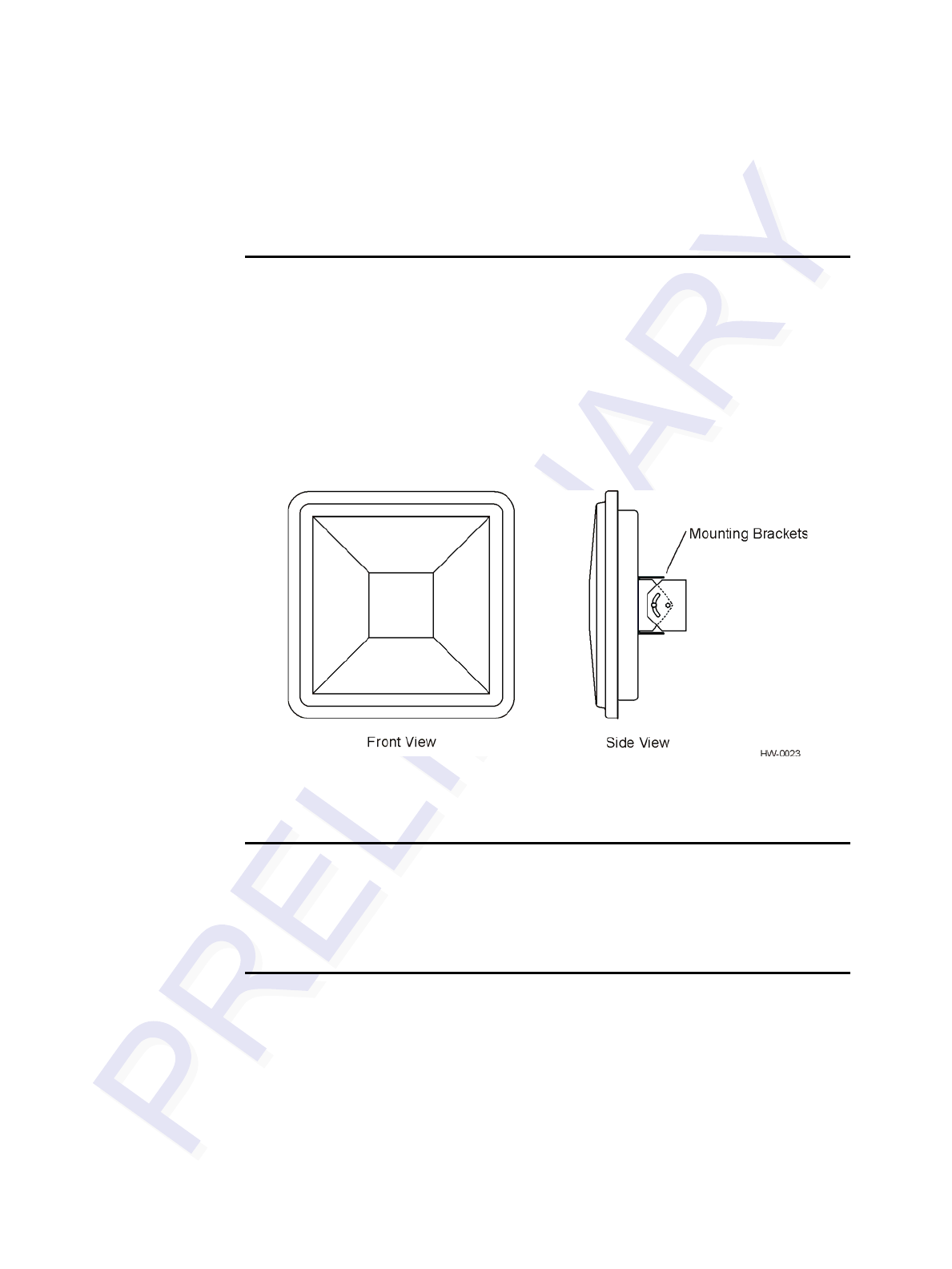
The Encompass 4/4800 Multiprotocol Reader System is a full-frame high-power unit
that can read both half-frame and full-frame tags. The reader output power can be
adjusted using reader commands.
Reader
The Encompass 4/4800 Multiprotocol Reader System consists of an input/output (I/O)
module, a power supply, a reader logic board (also called a tag decoder), a radio fre-
quency (RF) transmitter/receiver (called the RF module), and a patch antenna.
A second version of the Encompass 4/4800 Multiprotocol Reader is designed to be
used with a high-performance external antenna. These Encompass 4/4800 Multiproto-
col Reader System components are contained in a highly reliable, compact, and easy-
to-install environmentally-sealed package. Figure 1-1 shows the front and side views
of an Encompass 4/4800 Multiprotocol Reader System.
Figure 1-1 Encompass 4/4800 Multiprotocol Reader System Front and Side
Views
Tags
The Encompass 4/4800 Multiprotocol Reader System has the capability to read the
Intellitag-based eGo Windshield Sticker Tag as well as TransCore ATA protocol and
TransCore ISO-compliant read-only full- and half-frame tags.
How It Works
The Encompass 4/4800 Multiprotocol Reader System directs the RF module to gener-
ate an RF signal, which is broadcast through the internal or external antenna. Entering
the Encompass 4/4800 Multiprotocol Reader System’s reading range, a TransCore
RFID tag installed on a vehicle or other object to be tracked adds its programmed
identification information to the signal and reflects the signal back to the Encompass
4/4800 Multiprotocol Reader System. The Encompass 4/4800 Multiprotocol Reader
System receives this modified, or modulated signal, and decodes the tag data carried
by the reflected signal and transmits this data to a local host computer for processing.

Introduction
1-7
Licensing Requirements
An FCC license provides the user with the legal authorization to operate the Encom-
pass 4 on the licensed frequencies at the site specified in the license. Only an autho-
rized installer or service technician can set the RF frequency of the Encompass 4/4800
Multiprotocol Reader System to the frequency specified in the FCC site license. No
end-user-operated controls exist on the Encompass 4/4800 Multiprotocol Reader Sys-
tem.
The FCC license also provides the user with protection and authorization to maintain
the system should any other RFID product be used in the licensed area after the
Encompass 4/4800 equipment is installed.
Users of the Encompass 4/4800 Multiprotocol Reader System in the United States
must obtain a license from the FCC. The authorized frequency band for this product in
the United States is 912.5 to 919 MHz.
The user is responsible for filing the FCC license according to FCC regulations, but
the TransCore dealer will provide assistance and support as necessary to complete
these forms. Forms are available online at the FCC internet site http://www.fcc.gov/
formpage.html. For further information on obtaining the license contact TransCore.
Technical Support
Authorized dealers and distributors are responsible for the direct support of all
customers. Authorized dealers and distributors needing technical support can contact:
Technical Support
Phone: (800) 755-0378
Web: transcore.com/rfidsupport
or
TransCore
3410 Midcourt Road, Suite 102
Carrollton, Texas 75006 USA
Phone: (214) 461-4031
Fax: (214) 461-6478
Please be prepared to answer a series of questions that are designed to direct you to the
best support resource available.

Encompass 4/4800 Multiprotocol Reader System Guide
1-8

2
Developing the Site Plan


2-3
Chapter 2
Developing the Site Plan
This chapter discusses site plan development for installing the
EncompassTM 4/4800 Multiprotocol Reader System.
Overview
Developing a site plan provides the foundation for the site’s system design and estab-
lishes the following system configuration parameters:
•Number and general location of primary components
•Number of different radio frequencies required
Gathering relevant site information is crucial before applying for Federal Communi-
cations Commission (FCC) approval and ordering and installing Encompass 4/4800
Multiprotocol Reader(s) and tags.
Also, consider the following factors when developing a site plan:
•Type of tags used in the facility
•Reader and/or antenna and tag alignment
•Site layout and traffic flow
•Encompass 4/4800 Multiprotocol Reader and/or antenna mounting requirements
•Encompass 4/4800 Multiprotocol Reader electrical requirements
•Encompass 4/4800 Multiprotocol Reader communications requirements
These factors provide relevant information regarding each site’s physical and electro-
magnetic environment and the conditions under which the system must perform.
Reading of Mixed Population Tags
The Encompass 4/4800 Multiprotocol Reader reads the American Trucking Associa-
tion (ATA) and International Organization for Standardization (ISO) read-only tags,
whether powered by battery or beam, or application-specific integrated circuit
(ASIC)-based tags with Intellitag technology. The reader can read the ATA or ISO
read-only tags in the presence of Intellitag-based tags; however, attempting to read an
Intellitag-based tag in the presence of an ATA or ISO read-only tag is not recom-
mended.
Encompass 4/4800 Multiprotocol Reader System Guide
2-4
Caution
Attempting to read an Intellitag-based tag in the presence of an ATA or ISO read-only
tag may provide unreliable results.
The factors that influence the readability include, but are not limited to physical orien-
tation and configuration, type of read-only tag, ratio of backscatter cross-section of the
tags, and whether the tag is battery- or beam-powered.
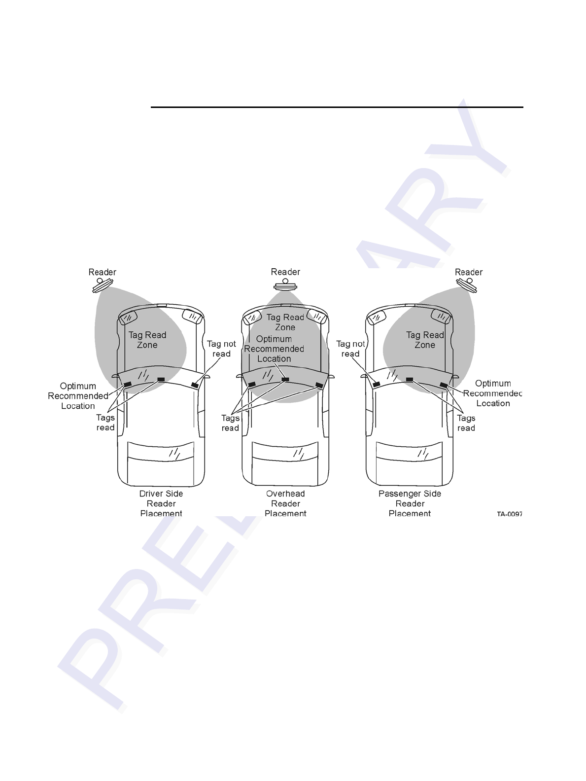
Reader and Tag Alignment
The position of the Encompass 4/4800 Multiprotocol Reader and placement of the tag
on the vehicle must be compatible. Also, consider any existing tagged vehicles now
using the facility to determine the optimal Encompass 4/4800 Multiprotocol Reader
location and orientation at the site.
Note: If any of the vehicles using your facility already have tags, such as those used
in toll applications, contact TransCore at 1-800-755-0378 for information about
mixed-tag installations before you plan tag type, location, and programming.
Three primary criteria must be satisfied to achieve the highest read reliability:
•Polarization of the tag and the Encompass 4/4800 Multiprotocol Reader must be
aligned in the same direction — both horizontal.
•The installed tag must be in a direct, unobstructed line of sight to the Encompass
4/4800 Multiprotocol Reader .
•Tags designed to be mounted in a vehicle windshield must be mounted in the vehi-
cle’s windshield, and tags designed to be mounted on the exterior surface of the
vehicle must be mounted on the exterior surface of the vehicle.
Caution
A tag may not be reliably read unless the preceding criteria are met.
Developing the Site Plan
2-5
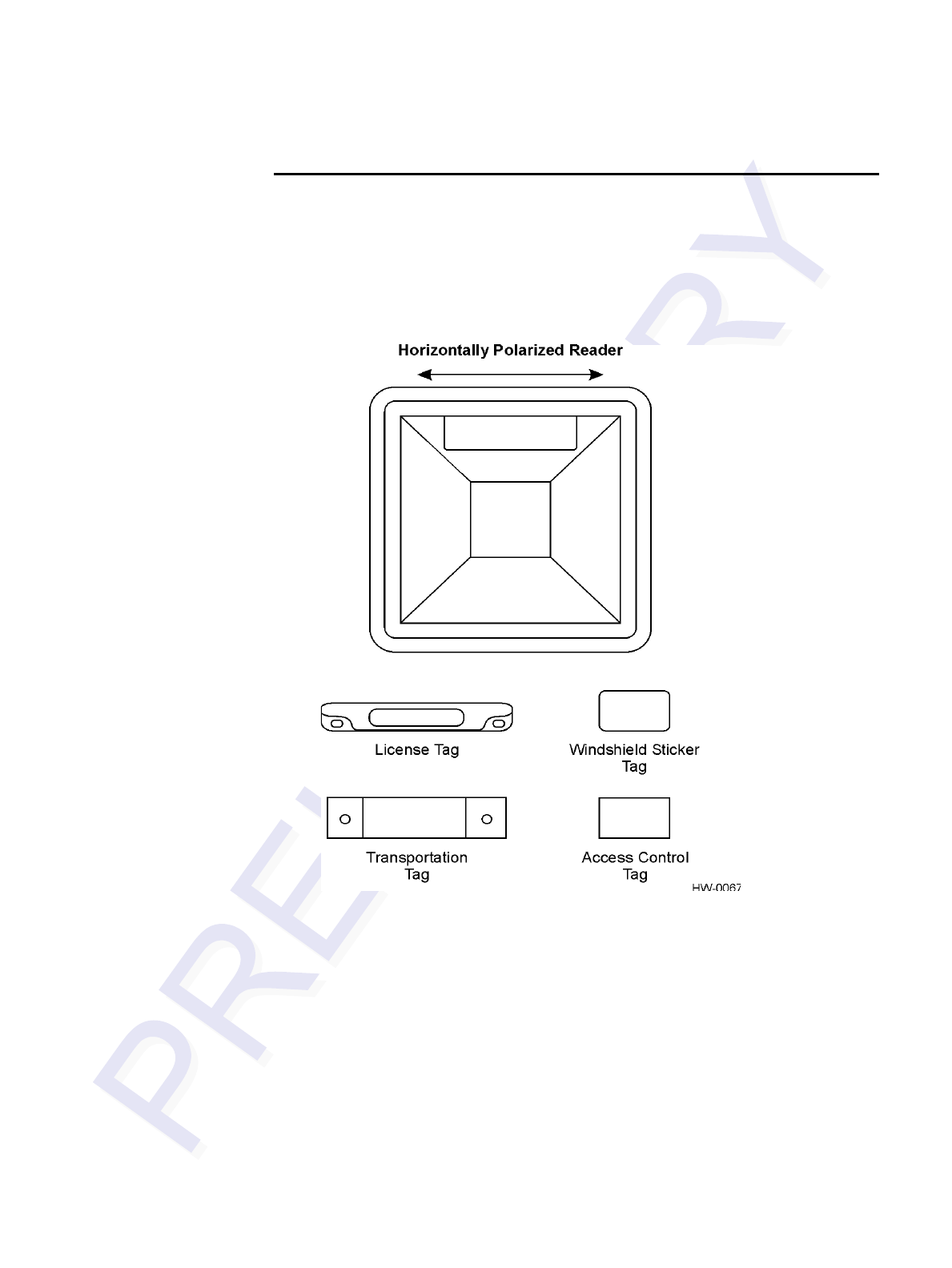
Polarization
The polarization of the tag must be aligned in the same direction as the Encompass
4/4800 Multiprotocol Reader, as shown in Figure 2-1.
Note: Matching the tag and antenna polarization is critical to obtain optimal system
performance.
Figure 2-1 Tag and Reader Orientation
Encompass 4/4800 Multiprotocol Reader System Guide
2-6
Unobstructed Line of Sight
For optimum readability, install the Encompass 4/4800 Multiprotocol Reader and the
vehicle’s tag so that when the vehicle approaches the Encompass 4/4800 Multiproto-
col Reader, the tag is directly facing the reader and the line of sight is clear between
the Encompass 4/4800 Multiprotocol Reader and the tag. If a fence or barrier is
between the tag and the reader, the Encompass 4/4800 Multiprotocol Reader cannot
reliably read the tags. Figure 2-2 illustrates possible installation locations of an
Encompass 4/4800 Multiprotocol Reader in relation to a tag’s mounting location on a
vehicle. If the tags are not in the recommended location, reliable optimum operation
requires lower vehicle speeds.
Figure 2-2 Encompass 4/4800 Multiprotocol Reader Location Relative to Tag
Position

Developing the Site Plan
2-7
If the Encompass 4/4800 Multiprotocol Reader is installed on a pole or wall to the left
of the vehicle, optimal tag position is on the left side of the vehicle as illustrated in
Figure 2-3.
Figure 2-3 Typical Tag Positions for U.S. Driver’s Side Reader
If an Encompass 4/4800 Multiprotocol Reader is installed on a pole or wall to the right
of the vehicle, optimal tag position is on the right side of the vehicle as illustrated in
Figure 2-4.
Figure 2-4 Typical Tag Positions for U.S. Passenger’s Side Reader
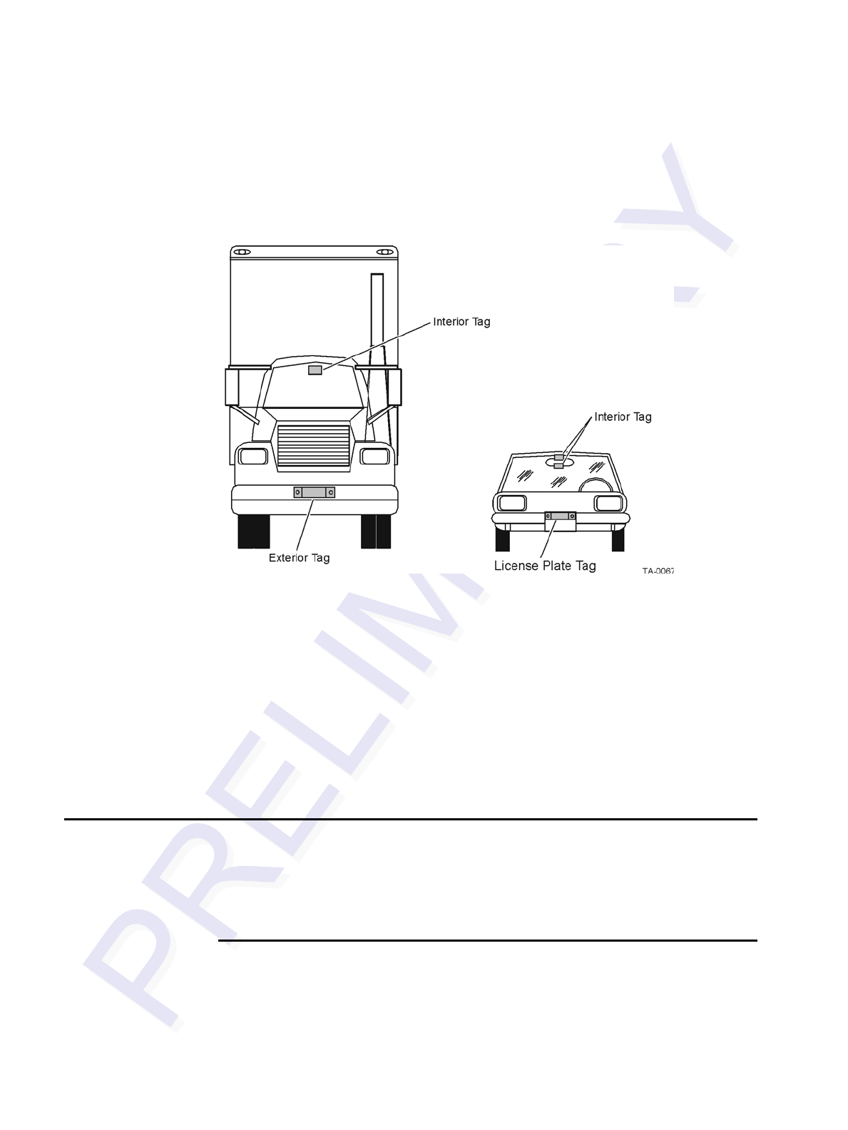
Encompass 4/4800 Multiprotocol Reader System Guide
2-8
If the Encompass 4/4800 Multiprotocol Reader is installed in an overhead location,
optimal tag position is in the top center of the windshield in the area behind the rear
view mirror or on the vehicle’s front license plate or center bumper as illustrated in
Figure 2-5.
Figure 2-5 Typical Tag Positions Used with Overhead Reader
Note: Metallized coatings on some vehicle windshields and windows shield the RF
energy emitted by the Encompass 4/4800 Multiprotocol Reader and may cause tags to
be misread. Many metallized windshields have areas that are not metallized in which
the tag can be placed and reasonable results achieved. If there are no openings in the
metallized coating in which to install an interior tag, install exterior-type tags on the
exterior of the vehicle.
Refer to Chapter 3 “Choosing, Installing, and Removing Tags” for more detailed
information on tag positioning.
Antenna Selection
This section contains guidelines that assist in antenna selection for an Encompass
4/4800 Multiprotocol Reader installation that uses an external antenna. The following
antennas are compatible with the Encompass 4/4800 Multiprotocol Reader installa-
tion.
AA3100 Yagi (without radome)
Appropriate for installations with the following requirements and conditions:
•902 to 928 MHz operation
•Non-icing environments

Developing the Site Plan
2-9
•Relatively symmetrical reading range
•Antenna profile not a major consideration
AA3101 Yagi (with radome)
Appropriate for installations with the following requirements and conditions:
•902 to 928 MHz operation
•Exposure to harsh environments
•Relatively symmetrical reading range
•Antenna profile not a major consideration
AA3110 Parapanel
Appropriate for installations with the following requirements and conditions:
•902 to 928 MHz operation
•Exposure to harsh environments
•Broad radiation pattern in one dimension, narrow in the other
•Low antenna profile
•Horizontal polarization
AA3140 PCB Log Periodic
Appropriate for installations with the following requirements and conditions:
•845 to 950 MHz operation
•Exposure to harsh environments
•Maximum coverage at close range (<20 ft [6.1 M])
•Vertical or horizontal polarization
AA3152 Universal Toll Antenna
Appropriate for installations with the following requirements and conditions:
•902 to 928 MHz operation
•Exposure to harsh environments
•Broadcast pattern of similar size and shape in both horizontal and vertical planes
•Low antenna profile

Encompass 4/4800 Multiprotocol Reader System Guide
2-10
AA3153 Toll Antenna
Appropriate for installations with the following requirements and conditions:
•902 to 928 MHz operation
•Exposure to harsh environments
•Broadcast pattern with virtually no side or back lobes, which helps confine cover-
age to a single lane width
•Low antenna profile
Antenna and Tag Alignment
The position of the antenna connected to the Encompass 4/4800 Multiprotocol Reader
and placement of the tag on the vehicle must be compatible. Also, consider any exist-
ing tagged vehicles now using the facility to determine the optimal Encompass 4/4800
Multiprotocol Reader antenna location and orientation at the site.
Note: If any of the vehicles using your facility already have tags, such as those used
in toll applications, contact TransCore at 1-800-755-0378 for information about
mixed-tag installations before you plan tag type, location, and programming.
Three primary criteria must be satisfied to achieve the highest read reliability:
•Polarization of the tag and the Encompass 4/4800 Multiprotocol Reader antenna
must be aligned in the same direction — both horizontal or both vertical.
•The installed tag must be in a direct, unobstructed line of sight to the Encompass
4/4800 Multiprotocol Reader antenna.
•Tags designed to be mounted in a vehicle windshield must be mounted in the vehi-
cle’s windshield, and tags designed to be mounted on the exterior surface of the
vehicle must be mounted on the exterior surface of the vehicle.
Caution
A tag may not be reliably read unless the preceding criteria are met.
Polarization
The polarization of the tag must be aligned in the same direction as the antenna con-
nected to the Encompass 4/4800 Multiprotocol Reader, as shown in Figure 2-1.
Note: Matching the tag and antenna polarization is critical to obtain optimal system
performance.
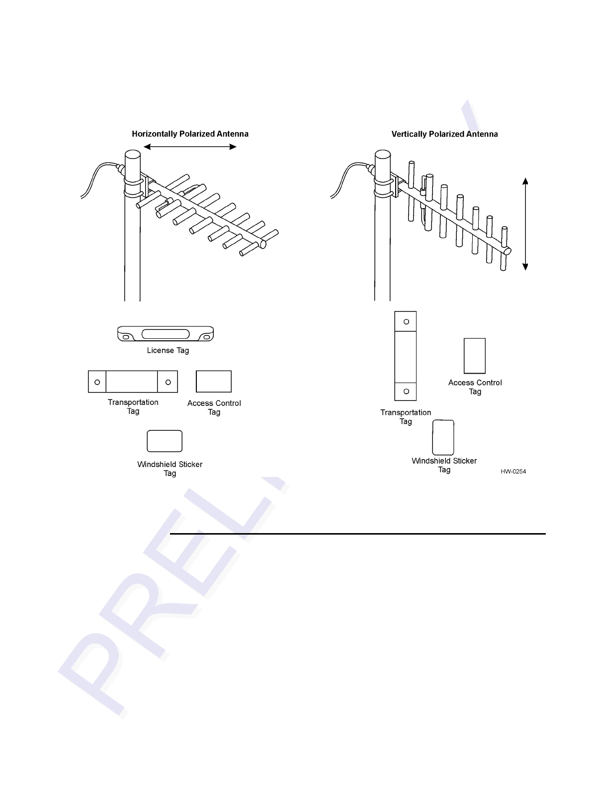
Developing the Site Plan
2-11
.
Figure 2-1 Horizontal and Vertical Tag Orientation
A horizontally oriented antenna cannot read a vertically oriented tag and vice versa.
Unobstructed Line of Sight
For optimum readability, install the Encompass 4/4800 Multiprotocol Reader antenna
and the vehicle’s tag so that when the vehicle approaches the antenna, the tag is
directly facing the antenna and the line of sight is clear between the antenna and the
tag. If a fence or barrier is between the tag and the antenna, the antenna cannot reliably
read the tags. Figure 2-2 illustrates possible installation locations of an Encompass 4/
4800 Multiprotocol Reader antenna in relation to a tag’s mounting location on a vehi-
cle. If the tags are not in the recommended location, reliable optimum operation
requires lower vehicle speeds.
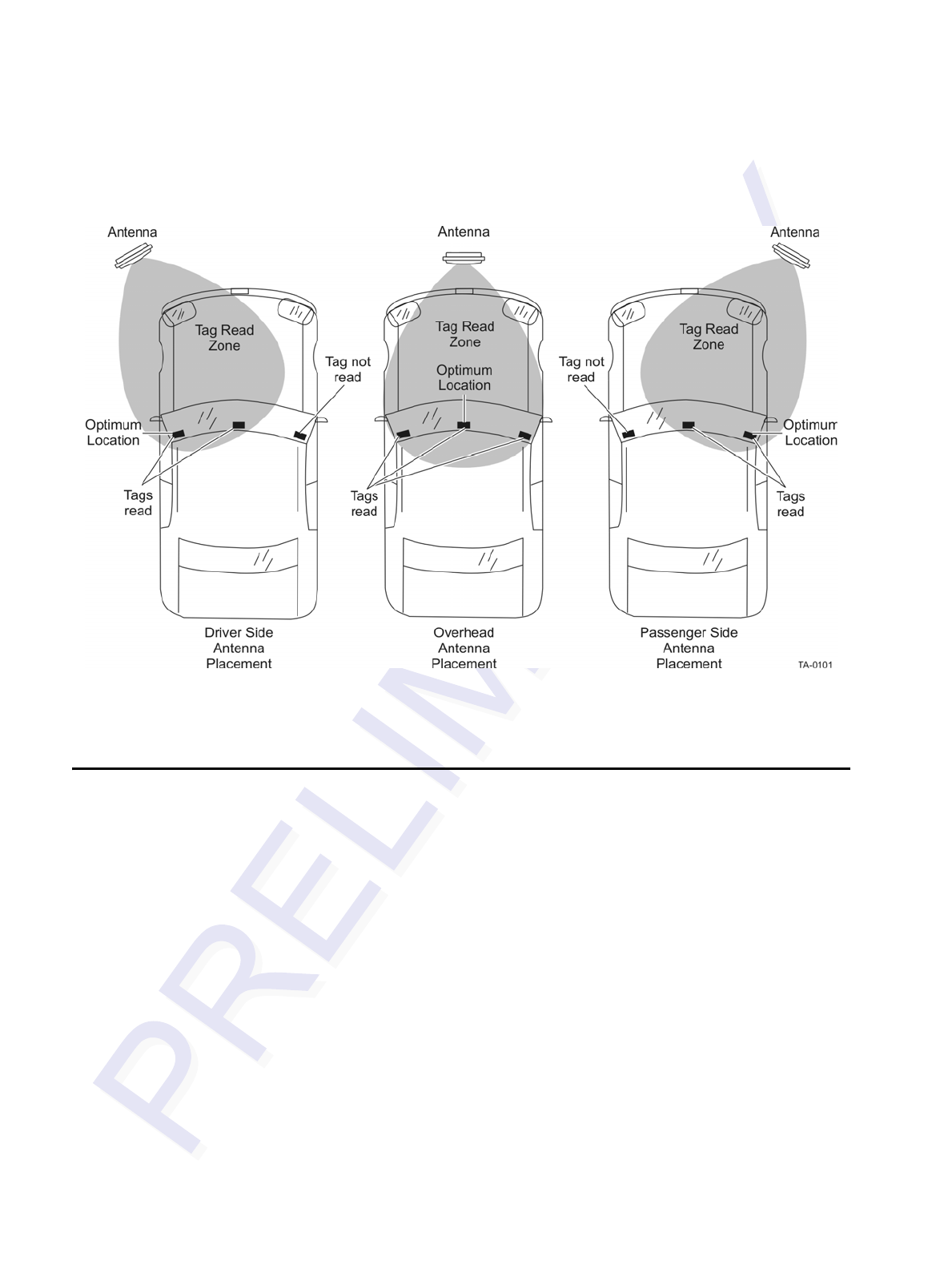
Encompass 4/4800 Multiprotocol Reader System Guide
2-12
Figure 2-2 Antenna Location Relative to Tag Position
Site Layout and Traffic Flow
The following site layout and traffic flow considerations are critical when determining
Encompass 4/4800 Multiprotocol Reader installation locations:
•The Encompass 4/4800 Multiprotocol Reader read zone
•Other Encompass 4/4800 Multiprotocol Reader units and antennas in the area
•Lane configurations
•Reflection, refraction, and diffraction of RF signals
•Existing signal interference at the site

Developing the Site Plan
2-13
The Encompass 4/4800 Multiprotocol Reader
Read Zone
The Encompass 4/4800 Multiprotocol Reader must be able to read the tag data prop-
erly within a specified area, called the read zone, without reading other nearby tags or
interfering with other Encompass 4/4800 Multiprotocol Readers at the site. The fol-
lowing are some of the factors that affect the size and shape of the read zone:
•Mounting method used (pole or wall mount)
•Mounting location (overhead or side mount)
•Height from the ground and mounting angle
•Mounting method used (pole or wall mount) of the antenna
•Mounting location (overhead or side mount) of the antenna
•Height from the ground and mounting angle of the antenna
•Indoor or outdoor location
•RF output attenuation
•Range discrimination setting
•Other sources of interference and reflection
The Encompass 4/4800 Multiprotocol Reader must be positioned to allow the RF sig-
nal to travel to and return from the tags within the designated range and be placed in
an area where it is not likely to be bumped out of alignment. If the antenna becomes
misaligned or some nearby structure is added or removed, system operation can be
seriously affected.
The external antenna must be positioned to allow the RF signal to travel to and return
from the tags within the designated range and be placed in an area where it is not
likely to be bumped out of alignment. If the antenna becomes misaligned or some
nearby structure is added or removed, system operation can be seriously affected.
For instructions on setting the read zone, see “Fine-Tuning and Verifying the Read
Zone” on page 8-20.
Other Encompass 4/4800 Multiprotocol Readers
in the Area
Sites with more than one Encompass 4/4800 Multiprotocol Reader in proximity
should have them configured with a frequency separation of at least 2 MHz from adja-
cent readers. If more than one Encompass 4/4800 Multiprotocol Reader is in a side-
by-side or multiple lane application, the frequencies should be staggered. Also,
Encompass 4/4800 Multiprotocol Readers may not operate accurately if they directly
face each other or are positioned back-to-back.

Encompass 4/4800 Multiprotocol Reader System Guide
2-14
If more than one Encompass 4/4800 Multiprotocol Reader and antenna is in a side-by-
side or multiple lane application, the frequencies should be staggered. Also, Encom-
pass 4/4800 Multiprotocol Readers may not operate accurately if the antennas directly
face each other or are positioned back-to-back.
Table 2-1 shows examples of staggered reader frequencies in a site with up to 14 read-
ers.
Lane Configurations
TransCore recommends that traffic be guided through a controlled lane to consistently
obtain accurate tag readings and to prevent physical damage to the Encompass 4/4800
Multiprotocol Reader . The following subsections describe some common lane con-
figurations and offer suggestions for positioning the Encompass 4/4800 Multiprotocol
Reader within the controlled traffic flow.
Gate with Center Island Configuration
Figure 2-3 illustrates a typical gate application with the Encompass 4/4800 Multipro-
tocol Reader units positioned on a center island to read tags mounted on the inside
windshield on the driver’s side (United States). The readers are placed to allow time
for the gate to open so the vehicle can roll through without stopping while not allow-
ing room for an untagged vehicle to be between the vehicle being read and the gate.
Table 2-1 Examples of Staggered Reader Frequencies
Lane Number Reader Frequency Lane Number Reader Frequency
1912.5 2915
3 917.5 4 913.5
5 916 6 918.5
7914.5 8917
9 913 10 915.5
11 918 12 914
13 916.5 14 919
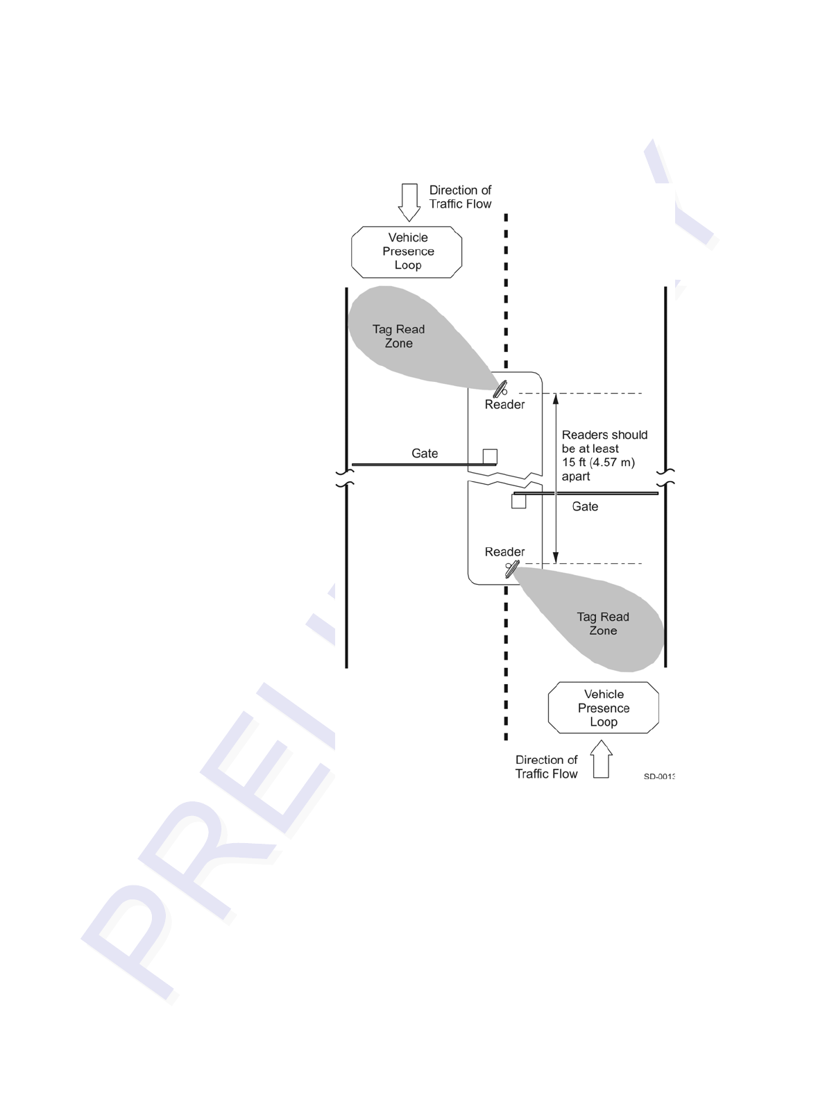
Developing the Site Plan
2-15
Figure 2-3 Gate Application with Center Island
Parking Garage with Ticket Island Configuration
Figure 2-4 illustrates a parking garage application with each Encompass 4/4800 Mul-
tiprotocol Reader mounted on the ticket island to read tags mounted on the inside cen-
ter windshield or on the center front vehicle bumper. The Encompass 4/4800
Multiprotocol Reader placement may require the vehicle to stop before the gate opens.
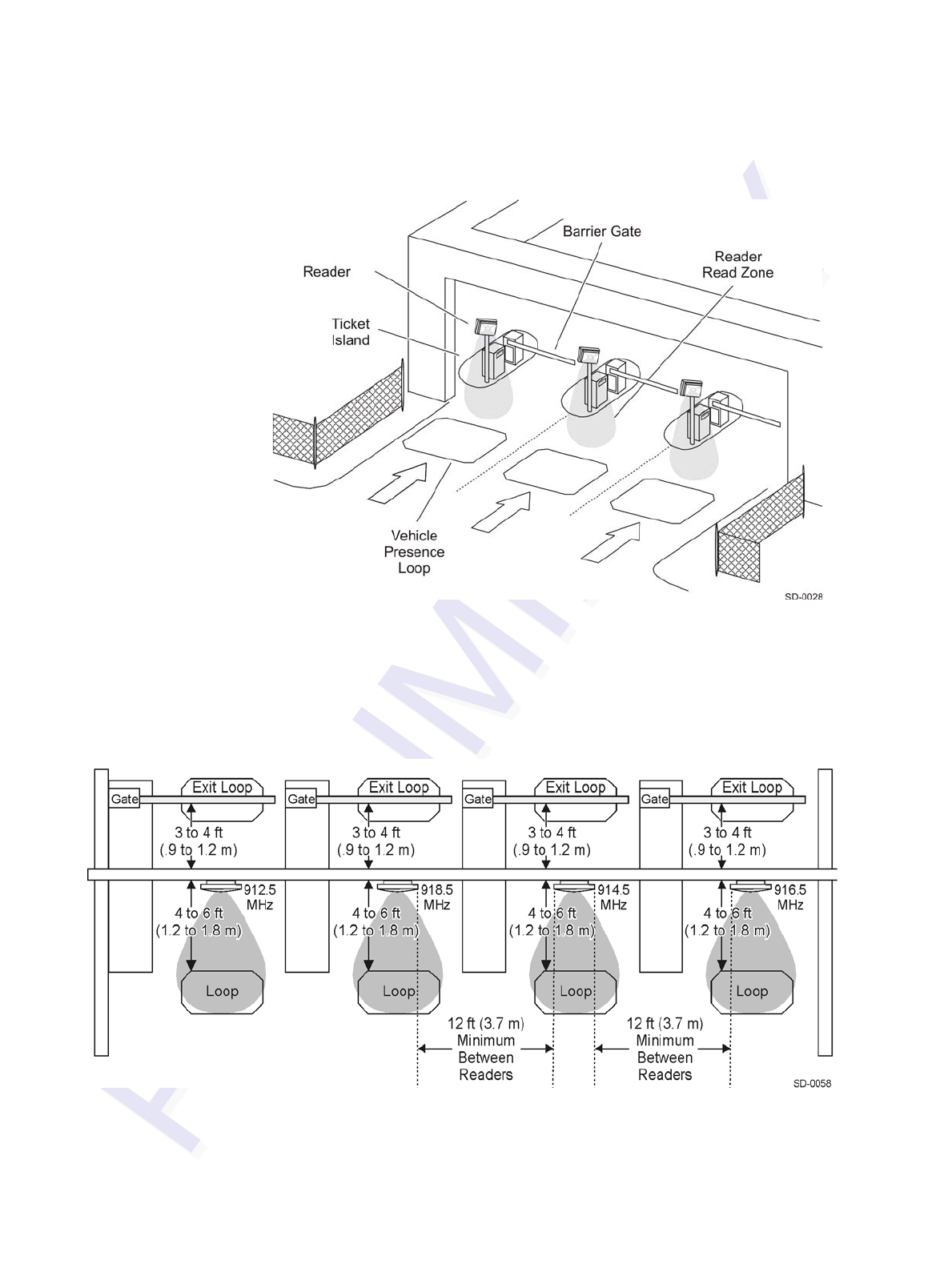
Encompass 4/4800 Multiprotocol Reader System Guide
2-16
Figure 2-4 Parking Garage Application
Overhead Reader Installation Configuration
Another option for Encompass 4/4800 Multiprotocol Reader placement is to mount it
overhead in each lane as illustrated in Figure 2-5. This illustration assumes that tags
are mounted on the inside center windshield or center bumper of the vehicle.
Figure 2-5 Overhead Installation
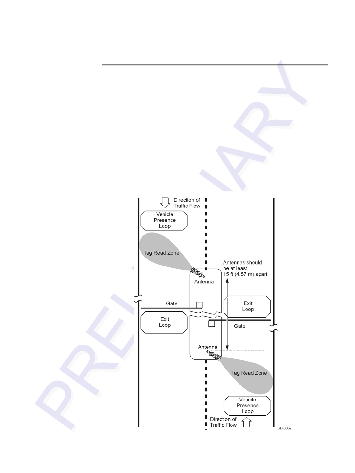
Developing the Site Plan
2-17
Lane Configurations for Encompass 4/4800 Multi-
protocol Readers Using an External Antenna
TransCore recommends that traffic be guided through a controlled lane to consistently
obtain accurate tag readings and to prevent physical damage to the Encompass 4/4800
Multiprotocol Reader and antenna. The following subsections describe some common
lane configurations and offer suggestions for positioning the external antenna within
the controlled traffic flow.
Gate with Center Island Configuration
Figure 2-3 illustrates a typical gate application with the readers and antennas posi-
tioned on a center island to read tags mounted on the inside windshield on the driver’s
side (United States). The antennas are placed to allow time for the gate to open so the
vehicle can roll through without stopping while not allowing room for an untagged
vehicle to be between the vehicle being read and the gate.
Figure 2-6 Gate Application with Center Island
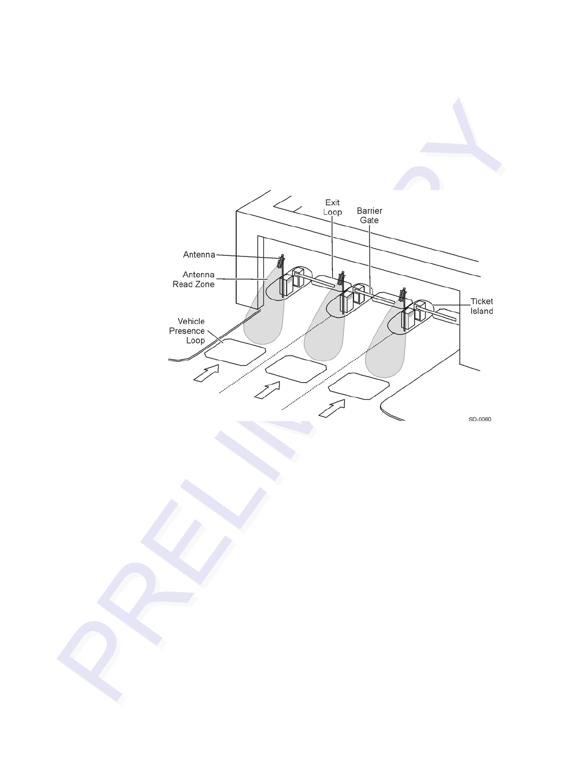
Encompass 4/4800 Multiprotocol Reader System Guide
2-18
Parking Garage with Ticket Island Configuration
Figure 2-4 illustrates a parking garage application with each Encompass 4/4800 Mul-
tiprotocol Reader and antenna mounted on the ticket island to read tags mounted on
the inside center windshield or on the center front vehicle bumper. The Encompass 4/
4800 Multiprotocol Reader antenna placement may require the vehicle to stop before
the gate opens.
Figure 2-7 Parking Garage Application
Overhead Reader Installation Configuration
Another option for Encompass 4/4800 Multiprotocol Reader antenna placement is to
mount it overhead in each lane as illustrated in Figure 2-5. This illustration assumes
that tags are mounted on the inside center windshield or center bumper of the vehicle.
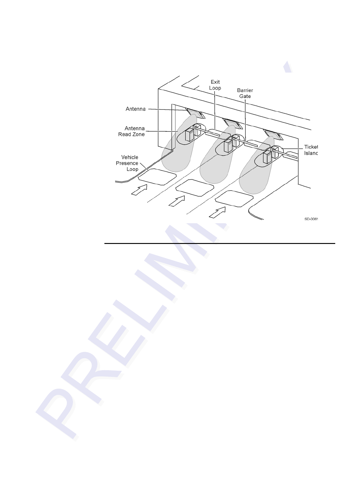
Developing the Site Plan
2-19
Figure 2-8 Overhead Installation
Reflection, Refraction, and Diffraction of RF
Signals
RF signals can be reflected, refracted, or diffracted by metal objects, walls, and even
wet pavement or ice. Any of these factors can alter or degrade system performance.
When designing your site plan, you must consider permanent structures and transient
factors in the vicinity that may affect RF signals being generated by the Encompass 4/
4800 Multiprotocol Reader. Permanent structures include buildings, chain link fences,
guard shacks, and gates. Transient factors include passing traffic and local weather
conditions, such as rain or snow. Symptoms of reflection, refraction, and diffraction
include reading tags that are out of the desired read zone or tags being read from
another lane.
The most common RF reflectors are metallic surfaces. RF signals may also be par-
tially reflected by nonconducting materials such as dirt, wood, ice, asphalt, and con-
crete. When nonconducting materials in the system environment become wet, they
increase reflection of RF signals.
The Encompass 4/4800 Multiprotocol Reader and/or antenna mounting location, aim-
ing, and range control adjustment, and use of presence detectors can reduce interfer-
ence from RF reflections. When these actions cannot adequately control reflections,
other techniques such as shielding, absorbing, range sensitivity adjustment, or barriers
can also be used. See Chapter 9, “Troubleshooting and Maintenance” for more infor-
mation.

Encompass 4/4800 Multiprotocol Reader System Guide
2-20
Existing Interference
Interference from RF and electrical sources can degrade system performance and must
also be considered in the site design. Fluorescent lights, neon signs, nearby radio sta-
tions, or power lines can interfere with the optimal operation of the system. The mag-
netic impulse noise from relays that control gate opening and closing can also disrupt
the RF signal.
Interference may degrade both reader and tag performance. Existing interference at
the site may be shielded, removed, or positioned further from the Encompass 4/4800
Multiprotocol Reader and/or antenna. In some cases, changing the operating fre-
quency of the Encompass 4/4800 Multiprotocol Reader may provide a simple solu-
tion. Readers in proximity should have at least a 2 MHz frequency separation. See
“Other Encompass 4/4800 Multiprotocol Readers in the Area” on page 2-13. Strong
RF sources of any frequency, in proximity to the tag, can preclude the tag receiving
the reader interrogation. See Chapter 9, “Troubleshooting and Maintenance.”
Electrical and Communications Requirements
All construction work at the site must be completed before installing the Encompass
4/4800 Multiprotocol Reader . Electrical and communications cables should be
installed according to all applicable local and federal building code requirements. Spe-
cific instructions for positioning and installing the Encompass 4/4800 Multiprotocol
Reader are discussed in Chapter 4, “Installing the Encompass 4/4800 Multiprotocol
Reader .”
Junction Box
Use a watertight junction box that meets applicable local and national building codes
for connecting power and communications wiring. The junction box houses the termi-
nal strip for power and communications connections. TransCore recommends a
NEMA Type-4 junction box with a back mounting panel.
Power and Communications Cables
Cable length for power and communications depends on the physical characteristics
of the Encompass 4/4800 Multiprotocol Reader installation site. Table 2-1 lists acces-
sory kits available for cabling options based on your site’s requirements.
Table 2-1 Connector Cabling Accessory Kits
Part Number Description
58-1620-001 5-ft connector cable harness
58-1620-002 20-ft connector cable harness

Developing the Site Plan
2-21
Electrical Power
A dedicated electrical power supply must be present at the site and available to the
Encompass 4/4800 Multiprotocol Reader at all times. The power must be 16-20V AC
or 16-28V DC. A step-down transformer is available (North America only) to convert
a 120V AC duplex wall outlet with ground to 18V AC, as is a step-up transformer to
convert a low-voltage 12V AC outlet to 18V AC. Consult your local and national elec-
trical codes for installation and safety requirements.
Note: Encompass 4/4800 Multiprotocol Readers installed outside North America
require a locally supplied transformer.
If 18V AC or 18V DC power is available, the transformer option is unnecessary.
TransCore offers a Class C transformer accessory kit (part number 76-1620-005) for
sites where 110V AC is available. It is the installer’s responsibility to supply conver-
sion equipment and wiring for other voltages. Table 2-2 contains power supply current
requirements.
Power circuits are protected internally against power surges.
Power Extension
Use Table 2-3 to determine the correct cable size according to the American Wire
Gauge (AWG) standard for the necessary length of extension cable. The numbers in
the first row of the table indicate cable size for the approximate cable length.
Note: If the cable is close to the maximum length, measure voltage at the Encompass
4/4800 Multiprotocol Reader with RF ON to ensure voltage does not drop below 16V.
A drop in voltage below 16V causes a reduction in read range and possible damage to
internal electronics as well as unreliable operation.
20-1620-003 Connector kit only
56-1620-004 13-pair cable (sold by the foot)
76-1620-005 110V AC to 18V AC Class C transformer
76-1620-006 12V AC to 18V AC step-up transformer
Table 2-2 Power Supply Current Requirements
Supply
(RF On)
Worst Case
Maximum Current at
68°F (20°C)
(RF Off)
Standby Operating
Current at 68°F
(20°C)
16 to 20V AC 1.7 A at 18V AC 1 A at 18V AC
16 to 28V DC 1.7 A at 18V DC 1 A at 18V DC
Table 2-1 Connector Cabling Accessory Kits (continued)
Part Number Description

Encompass 4/4800 Multiprotocol Reader System Guide
2-22
Table 2-3 Recommended Cable Length from Transformer to the Encompass 4/4800 Multiprotocol
Reader
Cable Size (AWG)a24 22 20 18 16 14 12
Maximum DCR (Ohms
per foot at 68°F)b0.0270 0.0175 0.0109 0.0069 0.0044 0.0027 0.0017
Maximum length (feet) 29.63 45.71 73.39 115.61 183.91 293.04 467.84
Maximum length (feet)c25 39 62 98 156 249 398
When used to extend
TransCore 5-ft cable
(feet)
23 36 57 90 143 227 363
When used to extend
TransCore 20-ft cable
(feet)
14 22 35 55 88 140 224
a. Use two conductors each for 18V and 18V return (4 conductors total on the TransCore cable
harness).
b. Direct current resistance (DCR) information is from the Belden catalog.
c. Calculated length is reduced by -15% to adjust for other variables such as connector contact
resistance. Length variable factor is 85%; maximum current drawn by the Encompass 4/4800
Multiprotocol Reader is 2.5 amps; maximum allowable voltage drop from the 18V AC trans-
former secondary is 2V.

Developing the Site Plan
2-23
Host Communications
Your site design must include communications between the Encompass 4/4800 Multi-
protocol Reader and a host computer. The Encompass 4/4800 Multiprotocol Reader
communicates with the host computer through an asynchronous serial line or through
a Wiegand interface. This serial line can be an
RS–232 interface or an RS–422 interface. The host computer must be able to accept
one of the interfaces shown in Table 2-4.
RS–232 Interface
Use an RS–232 interface if one or more of the following conditions apply to your site:
•The host computer system is 50 ft (15.2 m) or less from the Encompass 4/4800
Multiprotocol Reader .
•The host computer system is more than 50 ft (15.2 m) from the Encompass 4/4800
Multiprotocol Reader and a pair of RF modems or limited distance modem/line
drivers over copper wire are used for communications between the Encompass 4/
4800 Multiprotocol Reader and the host. The distance from the RF modem to the
Encompass 4/4800 Multiprotocol Readershould not exceed 50 ft (15.2 m).
•Other common communications devices that can extend the RS–232 distance,
such as fiber optic modems, have been selected.
The standard RS–232 connection maximum distance depends on the baud rate, cable
type, and the RS–232 device at the other end.
RS–422 Interface
Use an RS–422 interface if one or more of the following conditions apply to your site:
•The host computer is more than 50 ft (15.2 m) from the Encompass 4/4800 Multi-
protocol Reader .
•The host computer has an external limited-distance modem.
Table 2-4 Communications Interfaces and Conductor Requirements
Interface Number of
Conductors
RS–232 3
RS–232 with RTS and CTS hardware and handshake
signals 5
RS–422 4
Wiegand 3

Encompass 4/4800 Multiprotocol Reader System Guide
2-24
The standard RS–422 connection maximum distance depends on the baud rate, cable
type, and the RS–422 device at the other end.
Wiegand Interface
The Encompass 4/4800 Multiprotocol Reader can interface with equipment requiring
the Wiegand +5V DC data0-data1-ground interface. The reader uses the Wiegand
interface included with the RS–232 or RS–422 option.
Note: The Encompass 4/4800 Multiprotocol Reader comes from the factory with
either RS–232 and Wiegand or RS–422 and Wiegand. If you wish to use Wiegand, you
must first connect the Encompass 4/4800 Multiprotocol Reader using the RS–232 or
RS–422 interface, set all necessary operating parameters in the reader, then set the
Encompass 4/4800 Multiprotocol Reader ’s configuration to Wiegand, and then con-
nect the Encompass 4/4800 Multiprotocol Reader to the Wiegand interface.
Note: You must order tags programmed with Wiegand-formatted data when using a
Wiegand-compatible reader.
Input/Output Circuits
To connect the Encompass 4/4800 Multiprotocol Reader to external equipment such
as a treadle or traffic control light, install wires from these devices at the junction box.
The Encompass 4/4800 Multiprotocol Reader input circuit is designed to connect to a
dry contact closure. The Encompass 4/4800 Multiprotocol Reader output circuits are
single-pole, double-throw relays providing dry contact closures. These contacts are
rated at 42.2V AC peak (30Vrms) or 60V DC, at 1 A maximum with noninductive
load.
Output circuits are not intended for the direct control of electromechanical devices
such as motorized gates and barrier arms. For such applications, the Encompass 4/
4800 Multiprotocol Reader output circuits should be used to drive a secondary, appro-
priately rated high-power relay.
Antenna Interface
The site design must include an interface cable between the Encompass 4/4800 Multi-
protocol Reader and the compatible antenna chosen for the site. The antenna interface
is RF coaxial cable with male Type N sockets on each end.
Table 2-5 is a summary of coaxial cable performance. Figures indicate maximum
lengths of cable in feet.

Developing the Site Plan
2-25
a. Suffixes 50, 50A, and 50B indicate 50-ohm cables available from the
Andrew Corporation.
b. These cable lengths ensure optimal system performance (1 dB loss).
c. These cable lengths ensure adequate, but not optimal, system performance (3 dB
loss).
Table 2-5 Reader to Antenna Cable Performance
Cable TypeaOverall
Diameter (in.)
915MHz
Low Medium
Lossb Lossc
RG–223 0.216 6 18
RG–214 0.425 12 37
FHJ1–50 0.250 16 48
FSJ1–50 0.250 15 45
LDF2–50 0.375 28 85
FSJ4–50B 0.500 27 83
LDF4–50A 0.500 42 128
LDF5–50A 0.875 76 229
LDF6–50 1.125 103 310
LDF7–50A 1.625 122 366

Encompass 4/4800 Multiprotocol Reader System Guide
2-26

3
Choosing, Installing, and Removing
Tags


3-3
Chapter 3
Choosing, Installing, and Removing Tags
This chapter describes the various tag types compatible with the
EncompassTM 4/4800 Multiprotocol Reader and the procedures for
installing and removing compatible internal and external tags.
Compatible Tag Types
The Encompass 4/4800 Multiprotocol Reader provides the capability to read the vari-
ous TransCore eGo tags and other American National Standards Institute (ANSI)
ANS INCITS 256-2001-compliant tags with Intellitag technology. Depending on
options ordered, the Encompass 4/4800 Multiprotocol Reader can read eGo tags as
well as TransCore IT2000 (in optional ATA/ISO mode), ATA-protocol, ISO-compliant
tags, and eGo Plus tags when they are programmed to operate in ATA mode. It can
also read tags formatted to a wide range of industry-standard proprietary formats,
including SIA Wiegand 26-bit standard format.
The Encompass 4/4800 Multiprotocol Reader reads only the various TransCore eGo
tags.
See Appendix E for information about the numerous ATA-protocol tag models.
Reader and Tag Model Interoperability
Table 3-1 lists the tags that are read by the Encompass 4/4800 Multiprotocol Reader.
See http://www.transcore.com/pdf/Tag-Reader-Matrix.pdf for most current informa-
tion concerning readers and supported tag protocols.
Table 3-1 Tags Read by the Encompass 4/4800 Multiprotocol Reader
Reader Beam Tags Battery Tags
Encompass 4/4800 Multiprotocol
Reader AT5100; AT5102; AT5110;
AT5112; AT5125; AT5145;
AT5146; AT5715
eGo Windshield Sticker Tag;
eGo Tamper Resistant Tag; eGo
License Plate Tag
eGo Plus Sticker* Tag; eGo Plus
License Plate Tag*
other ANS INCITS 256-2001-
compliant tags with Intellitag
technology
AT5105; AT5114; AT5140;
AT5147; AT5510; AT5540;
AT5541; AT5542; AT5543;
AT5544; AT5545; AT5547;
AT5704; AT5707; IT2221**;
IT2235**
* in ATA and eGo modes ** When used in optional ATA/ISO
mode
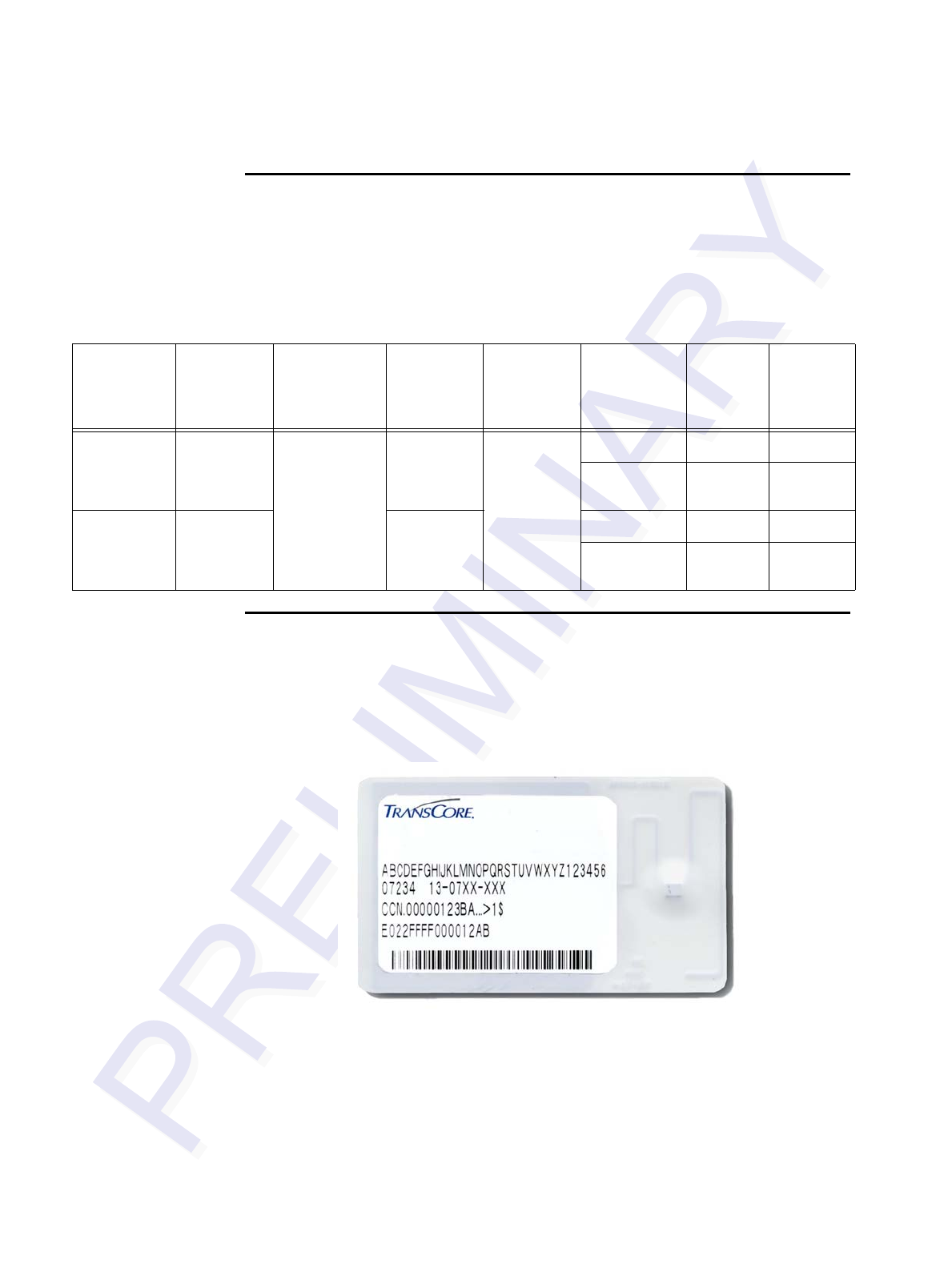
Encompass 4/4800 Multiprotocol Reader System Guide
3-4
TransCore’s eGo Tags
TransCore’s various eGo tags are offered to complete your Encompass 4/4800 Multi-
protocol Reader System.
Table 3-2 lists some of the features of the TransCore eGo tags.
Table 3-2 eGo Tag Features
eGo Windshield Sticker Tag
The TransCore eGo Windshield Sticker Tag (Figure 3-1) is offered to complete your
Encompass 4/4800 Multiprotocol Reader System. It is a flexible sticker much like a
vehicle registration sticker.
Figure 3-1 eGo Windshield Sticker Tag
Tag Part
Number Used For Special
Features Power
Source
Number
of 6-bit
ASCII
Characters
Number
of 128-
Bit
Frames
Number
of
Wiegand
Bits
Windshield
Sticker Tag 13-0510-
004 Toll,
Electronic
vehicle
registration
(EVR),
mCommerce,
Parking,
Security
access
Very thin,
flexible,
multi-layer
lamination
Beam 20 1 NA
10 1/2 26 to 54
License
Plate Tag 13-0510-
900 Water-
resistant,
exterior-
mounted
20 1 NA
10 1/2 26 to 54
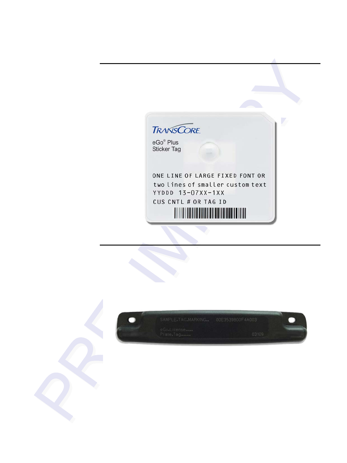
Choosing, Installing, and Removing Tags
3-5
eGo Plus Sticker Tag
The Encompass 4/4800 Multiprotocol Reader can also read the eGo Plus Sticker Tag
configured to support ATA or eGo modes.
Figure 3-2 eGo Plus Windshield Sticker Tag
eGo License Plate Tag
The eGo License Plate Tag (Figure 3-3) is a water-resistant tag used in applications
requiring an exterior-mounted eGo tag.
Figure 3-3 eGo License Plate Tag

Encompass 4/4800 Multiprotocol Reader System Guide
3-6
Intellitag Data Format
The memory of Intellitag-based tags consists of 128 bytes of non-volatile read/write
memory. Portions of tag data, such as the tag serial number, manufacturing location
code, and tag hardware type, are programmed at the factory and locked. The tag mem-
ory layout may be programmed by the end user and may be kept unlocked if desired.
Of the 128 bytes of memory, 12 bytes are programmed and locked at the factory and
116 bytes of user memory are available to be formatted and locked as required by the
application. Six bytes of the available 116 bytes of user memory are used for defining
tag memory layout.
Tags can be programmed in Wiegand formats with 26 to 54 bits. Users who choose
this tag data format must complete a Wiegand format worksheet — attached to the
Encompass 4/4800 Multiprotocol Reader order entry form — indicating the data to be
programmed into the tags.
Installing eGo Windshield Sticker Tags
eGo Windshield Sticker Tags are designed to be attached by a semi-permanent adhe-
sive to the interior surface of nonmetallic windshields 0.190 to 0.230 inches (4.82 to
5.84 mm) in thickness. For optimum performance, you must install the tag at least 2
inches (5 cm) from the metal in the windshield frame and 0.75 inch (1.9 cm) from the
rearview mirror support post. Detailed instructions are found in the pocket guide
"Quick and Easy Installation Instructions for Windshield Sticker Tag."
Some vehicles have a tinted area across the top of the windshield. If the tint is conduc-
tive, it can interfere with reading the tag. If a windshield has this conductive tint, the
tag must be installed at least 2 inches (5 cm) below this tinted area.
Some vehicle windshields contain a metallic treatment that could prevent an interior
windshield-mounted tag from being read. However, many of these metallized wind-
shields have areas that are not metallized. On a vehicle without open areas in its met-
allized windshield, you might need to install an Encompass 4/4800 Multiprotocol
Reader-compatible license plate tag on the vehicle. See the section “Installing eGo
License Plate Tags” on page 3-9 and the section “Installing ATA License Plate Tags”
on page 3-15. Contact TransCore for more information. See the section “Technical
Support” on page 9-7.
eGo Plus Sticker Tags are positioned and installed similarly to eGo Windshield Sticker
Tags. Detailed instructions are found in the pocket guide "Quick and Easy Installation
Instructions for the eGo® Plus Sticker Tag."
Required Materials
You need the following supplies to install windshield sticker tags:
•Glass cleaner, mild detergent and water, or any cleaning solution appropriate for
your windshield
•Clean, dry cloth
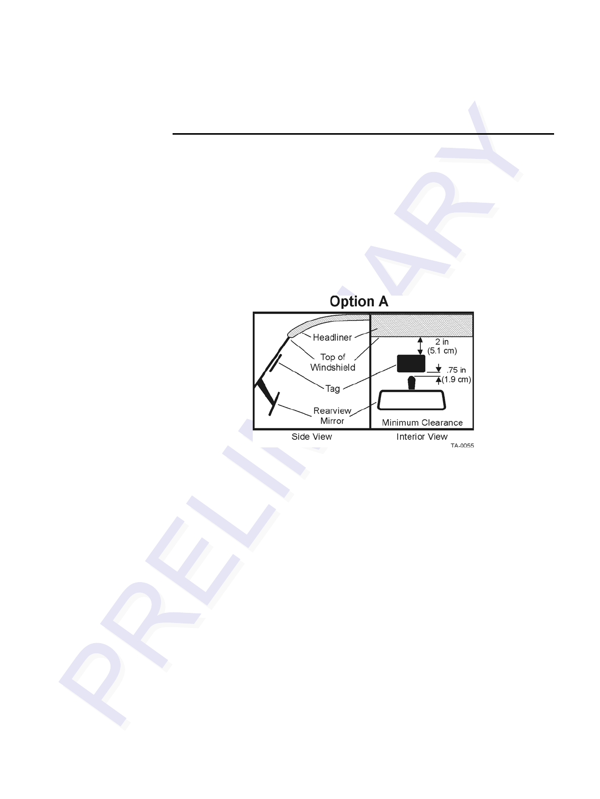
Choosing, Installing, and Removing Tags
3-7
•eGo Windshield Sticker Tag
Positioning eGo Windshield Sticker Tags
TransCore designed the eGo Windshield Sticker Tag to be installed on the upper cen-
ter or upper corner portion of the windshield. Figures Figure 3-4, Figure 3-5, and Fig-
ure 3-6 illustrate possible upper center tag placement locations. If the upper portion
of the windshield is tinted with an aftermarket conductive tint, use placement
Option B as shown in Figure 3-5.
Mirror Post Attached Low On Windshield
Choose placement Option A shown in Figure 3-4 if the mirror post is attached low on
the windshield.
Figure 3-4 eGo Windshield Sticker Tag Placement Option A
Mirror Post Attached High on Windshield
Choose placement Option B if the mirror post is attached high on the windshield as
shown in Figure 3-5 or if the upper portion of the windshield is tinted with a conduc-
tive tint.
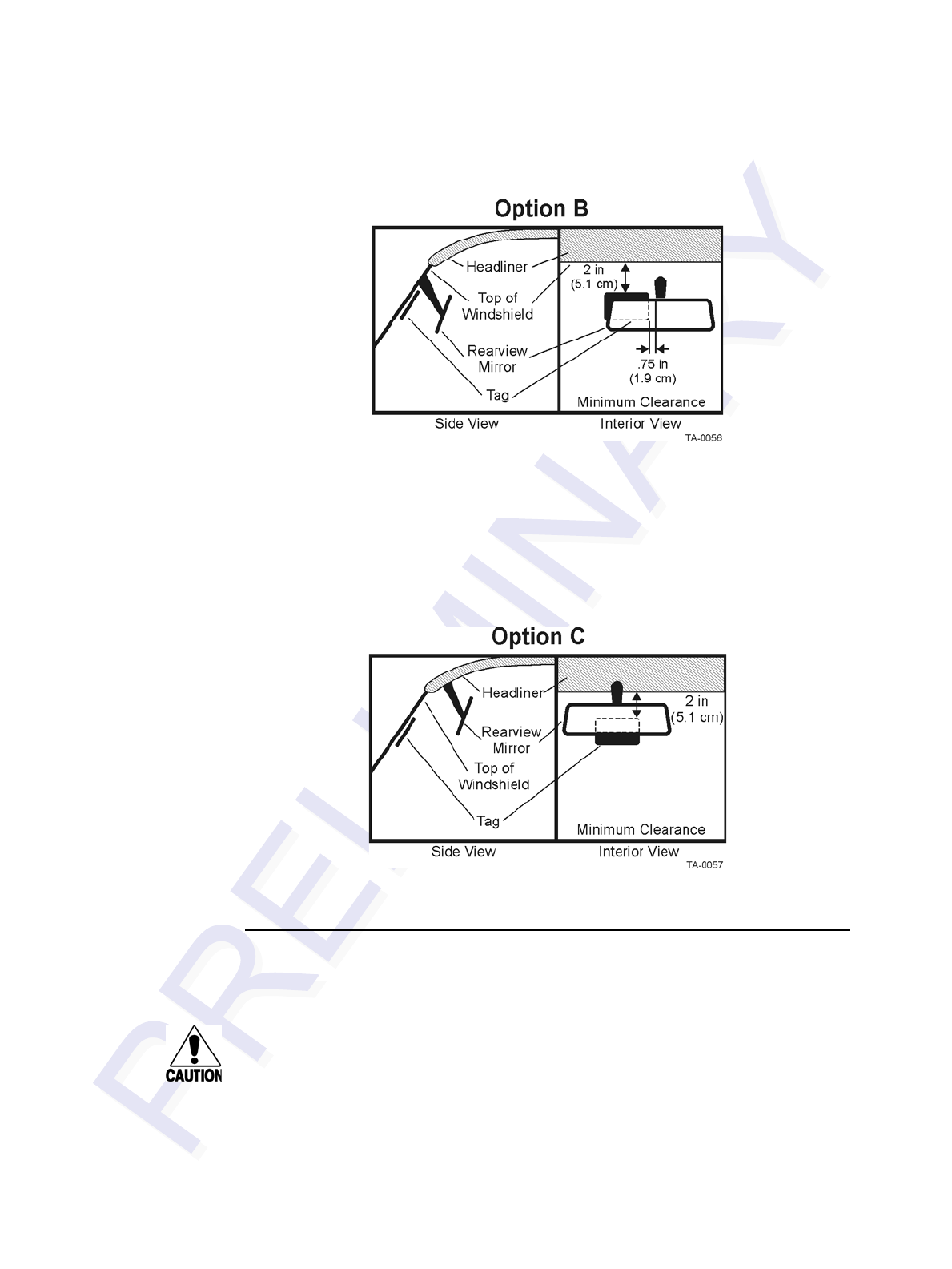
Encompass 4/4800 Multiprotocol Reader System Guide
3-8
Figure 3-5 eGo Windshield Sticker Tag Placement Option B
Mirror Post Attached to Headliner
Choose placement Option C if the mirror post is attached to the headliner as shown in
Figure 3-6. If the upper portion of the windshield is tinted with an aftermarket
conductive tint, place the tag two inches (5 cm) below the tinted area.
Figure 3-6 eGo Windshield Sticker Tag Placement Option C
eGo Windshield Sticker Tag Installation Proce-
dures
Caution
Confirm that the outside temperature is above 50°F (10°C). The sticker tag may not
adhere correctly if the temperature is below this temperature.

Choosing, Installing, and Removing Tags
3-9
To install the eGo Windshield Sticker Tag
1. Determine the tag installation location for the vehicle using the placement
guidelines in the section “Positioning eGo Windshield Sticker Tags” on page 3-7.
2. Thoroughly clean the interior surface of the windshield behind and around the
rearview mirror where the tag will be located.
3. Dry the tag location area thoroughly using a clean, dry cloth.
4. Remove the paper backing from the tag to expose the adhesive.
Caution
Ensure that the tag is correctly located before touching it to the glass. Once the
sticker tag is applied to the glass, it cannot be moved without damage to the tag.
5. Holding the sticker tag by its edges, position the tag in the correct area of the
windshield (determined in Step 1), making sure the tag is oriented horizontally
and is at least two inches (5 cm) from the windshield frame and 0.75 inch (1.9
cm) from the mirror post.
6. Press the sticker tag firmly against the glass and gently rub over the entire tag
surface. Ensure that no air bubbles remain between the sticker tag and the
windshield.
Removing eGo Windshield Sticker Tags
Removing eGo Windshield Sticker Tags requires the use of a razor blade or equivalent
tool. The tag is inoperable once removed.
Installing eGo License Plate Tags
Metallized coatings on some vehicle windshields and windows absorb the RF energy
emitted by the Encompass 4/4800 Multiprotocol Reader, thus causing tags to be mis-
read. You must use exterior license plate tags on vehicles with metallized coatings on
their windshields and windows.
Use license plate installation techniques to install tags on the exterior of vehicles that
have this type of window coating.
Note: The read zone of an overhead Encompass 4/4800 Multiprotocol Reader should
be adjusted accordingly when an exterior tag is installed on a license plate, or the
read zone will be reduced.
Required Materials
•Screwdriver (flat-blade or Phillips depending on the vehicle’s license plate
mounting screws)

Encompass 4/4800 Multiprotocol Reader System Guide
3-10
•Optional TransCore Exterior Tag Accessory Kit (19077-01). This kit contains
tamper-resistant mounting screws and wrench.
•eGo License Plate Tag
Positioning eGo License Plate Tags
The eGo License Plate Tag (LPT) is installed over the license plate at the upper part of
the vehicle’s front license plate area.
Note: If your state does not require a front license plate, install the LPT in the area
where the license plate would normally be mounted. If your vehicle does not have a
front license plate area, contact your tag agency for other tag options.
The orientation of the tag is important. The tag must be mounted so that the holes on
the tag base plate are on the top edge.
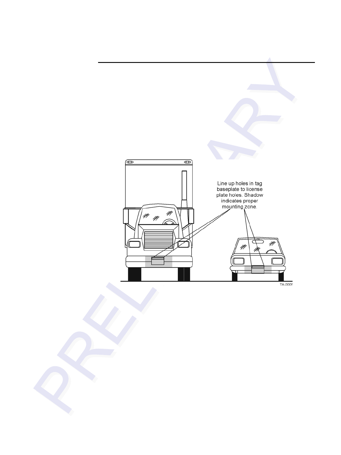
Choosing, Installing, and Removing Tags
3-11
eGo License Plate Tag Installation Procedures
To mount the eGo LPT
1. Remove the screws from the license plate area of your front bumper (Figure 1). If
your vehicle does not have mounting screws you will need two self-tapping
threaded screws. You can also contact the tag agency to inquire about the
optional TransCore Exterior Tag Accessory Kit.
Note: You may need to use longer screws to fasten the LPT over the top area of your
license plate.
Figure 3-7 Correct Mounting Location for LPT
2. Position the LPT so that it is within 18 inches (46 cm) of the center of the front
bumper as shown by the shaded area in Figure 3-7. If your vehicle’s license plate
mounting area is more than 18 inches (46 cm) from the center, you may need to
select an alternate location to mount the tag. Contact your tag agency if your
vehicle requires an alternate mounting location for the LPT.
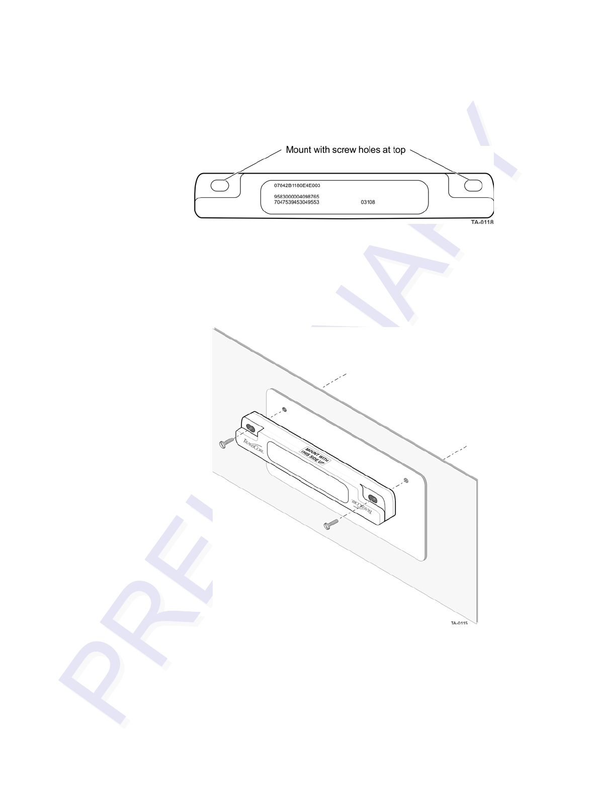
Encompass 4/4800 Multiprotocol Reader System Guide
3-12
3. Hold the LPT so that the etched lettering is facing you with the mounting holes to
the top as shown in Figure 3-8.
Figure 3-8 Correct Tag Orientation
4. Fasten the LPT to the bumper using the license plate mounting screws
(Figure 3-9). Install the LPT over the top area of the vehicle’s license plate if your
vehicle has a front license plate. If your state does not require a front license
plate, install the LPT in the area where a license plate would normally be
mounted.
Figure 3-9 Upper Placement Over the Top Area of the License Plate

Choosing, Installing, and Removing Tags
3-13
Installing Interior ATA Tags
Interior ATA-protocol tags are installed using hook-and-loop material or double-sided
tape attached to the tag and to the windshield. When using hook-and-loop material,
the loop material should be applied to the back of the tag and the hook material should
be applied to the windshield. After the tag is installed, it can be removed easily and
used in any vehicle that has corresponding hook material affixed to the windshield.
Note: Installing interior tags using double-sided tape results in a semipermanent
attachment; the tag will be more difficult to remove than one installed using hook and
loop material.
Interior ATA-protocol tags may be ordered from the factory with hook-and-loop
material or double-sided tape already applied to the tag. The adhesive on this material
is specially formulated for temperature extremes inside vehicles.
Required Materials
You will need the following materials to install interior tags:
•Rubbing alcohol or 50/50 isopropyl alcohol and water
•Sponge and dry cloth
•Interior tags with two strips of factory-installed hook-and-loop material or fac-
tory-installed double-sided tape attached
Positioning ATA Tags
Interior ATA-protocol tags can be installed on the driver’s side, passenger’s side, or
upper center of the vehicle’s windshield, depending on the Encompass 4/4800
Multiprotocol Reader’s position. See “Reader and Tag Alignment” on page 2-4.
Tags should be mounted consistently in all vehicles using a particular Encompass 4/
4800 Multiprotocol Reader facility.
Interior Driver’s or Passenger’s Side
TransCore designed interior ATA-protocol tags for installation inside the vehicle, typ-
ically on the driver’s side of the windshield. Install the tag in the upper corner, at least
two inches (5 cm) from the metal window post, as shown in Figure 3-10.
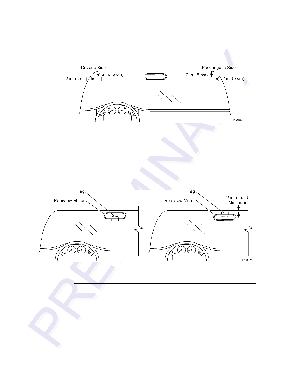
Encompass 4/4800 Multiprotocol Reader System Guide
3-14
Figure 3-10 Driver’s or Passenger’s Side (U.S.) Interior Windshield Tag Location
Interior Center Windshield
You may also install ATA tags on the upper center portion of the windshield. Position
the tag as closely as possible to the windshield’s upper center, behind the rearview
mirror. The top edge of the tag should be approximately one inch (2.5 cm) below the
base of the mirror, or above the base if enough room is available for the tag to be two
inches (five cm) from metal around the windshield, as shown in Figure 3-11.
Figure 3-11 Upper Center Interior Windshield Tag Location
ATA Interior Tag Installation Procedures
Perform the following steps to install interior tags:
1. Clean the tag installation area on the interior surface of the windshield with
rubbing alcohol.
2. Dry the area thoroughly using a clean, dry cloth.
3. Remove the clear backing from the two strips of hook-and-loop material on the
back of the tag (Figure 3-12) or from the double-sided tape.
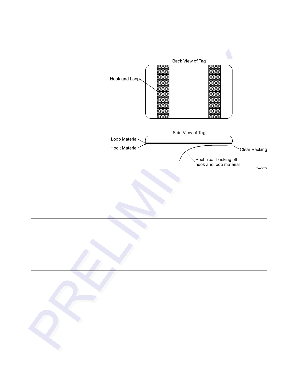
Choosing, Installing, and Removing Tags
3-15
Figure 3-12 Hook-and-Loop Material on Interior Tag
4. Position the tag over the correct area of the windshield, making sure that the tag
and reader orientation are the same (horizontal or vertical).
5. Press the tag firmly against the glass.
Removing Interior ATA Tags
To remove an interior ATA-protocol tag installed using hook-and-loop material,
simply pull the tag away from the windshield.
To remove an interior ATA-protocol tag installed using double-sided tape, slowly pry
off the tag with a thin tool, such as a putty knife.
Installing ATA License Plate Tags
Metallized coatings on some vehicle windshields and windows absorb the RF energy
emitted by the Encompass 4/4800 Multiprotocol Reader, thus causing tags to be mis-
read. Use exterior license plate tags on vehicles with metallized coatings on wind-
shields and windows.
Use license plate installation techniques to install tags on the exterior of vehicles that
have this type of window coating.
Note: The read zone of an overhead Encompass 4/4800 Multiprotocol Reader should
be adjusted accordingly when an exterior tag is installed on a license plate, or the
read zone will be reduced.
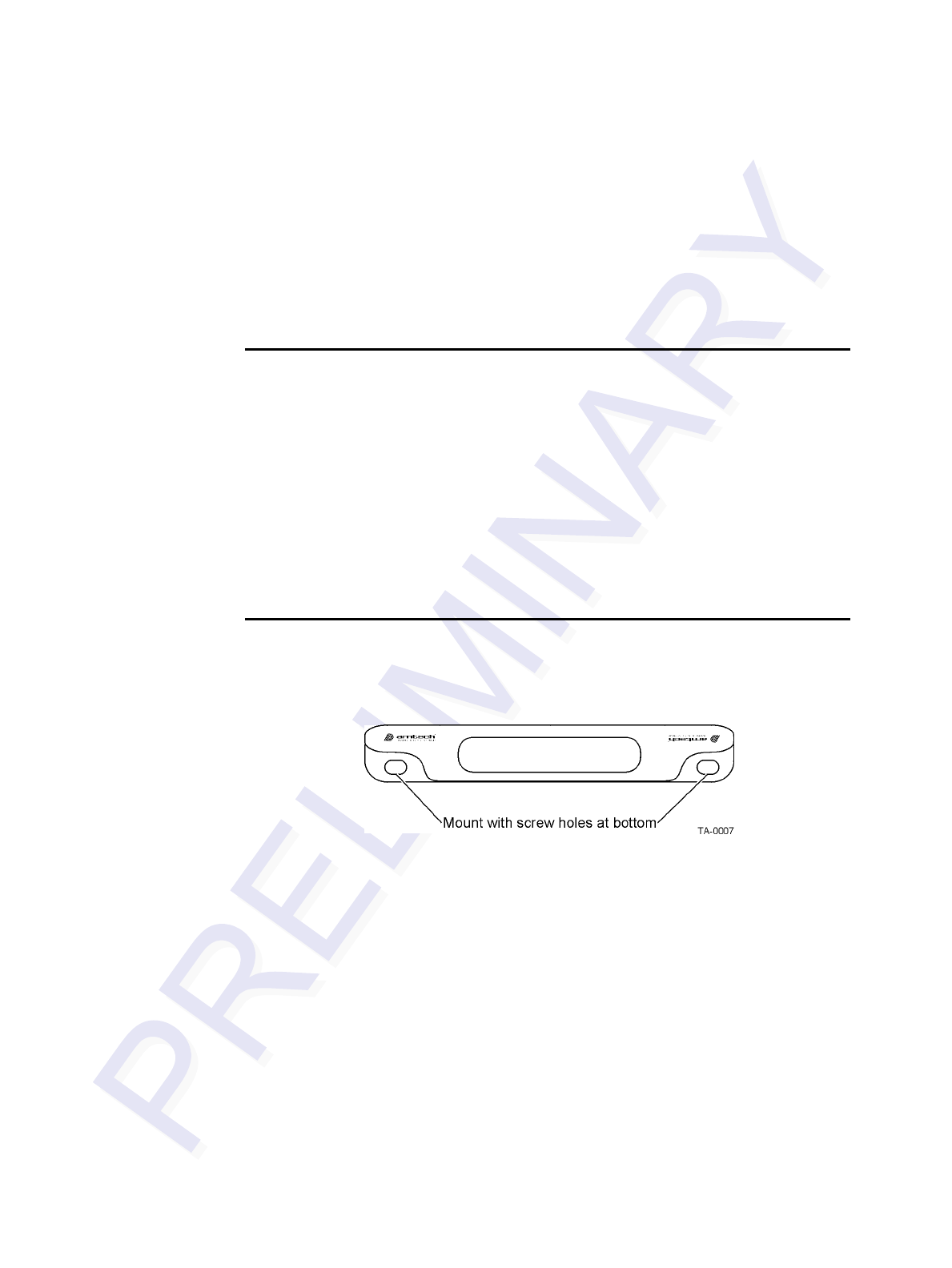
Encompass 4/4800 Multiprotocol Reader System Guide
3-16
Exterior tags may be installed on metal or plastic bumpers using the existing license
plate bracket and hardware.
The tag can be mounted on the front bumper where the license plate is normally
located or mounted directly to the front license plate or license plate bracket. Once
installed, the face of the tag should be pointing directly forward or slightly upward. If
the bumper, license plate, or license plate bracket has any material that overhangs the
tag, the tag will not function properly.
Required Materials
You need the following supplies to install license-plate mounted tags:
•Exterior license plate-mount tag
•Two 0.25-inch (.63 cm) bolts and nuts (user-supplied). Length of the bolts can
vary depending on vehicle model.
•Screwdriver and wrench (user-supplied)
•0.25-inch (.63 cm) spacers or washers (if needed). Thickness of spacers can vary
depending on vehicle model.
Positioning ATA License Plate Tags
The orientation of the tag is important. The tag must be mounted so that the holes on
the tag base plate are on the bottom edge. See Figure 3-13.
Figure 3-13 Proper Tag Orientation
When positioning the tag, observe the following guidelines:
•The tag should be horizontal and parallel to the ground.
•The tag face should be perpendicular or tilted slightly upward.
• The tag may lean to the rear a maximum of 30 degrees.
• The tag may lean to the front a maximum of 10 degrees.
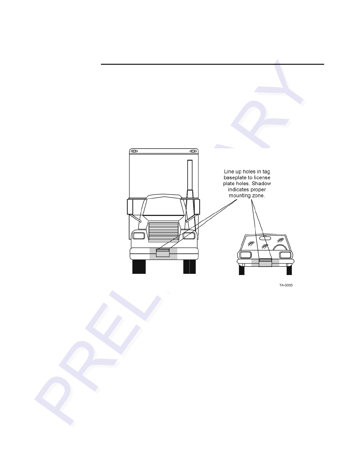
Choosing, Installing, and Removing Tags
3-17
ATA License Plate Tag Installation Procedures
To mount the license plate tag
1. Position the tag so that the holes in the tag are on the bottom edge and the tag is
within 18 inches (.45 m) of the center of the front bumper as illustrated by the
shaded area in Figure 3-14.
Note: When mounting an exterior tag on heavy trucks or tractors, the tag must
be mounted within 1.5 inches (3.81 cm) of the top of the bumper.
Figure 3-14 Correct Exterior Tag Placement
2. Line up the holes in the tag as follows:
• If mounting the tag to a license plate or license plate bracket, line up the
holes in the tag to the upper holes of the license plate or license plate
bracket.
Note: Do not mount the tag to the bottom holes of the license plate or license
plate bracket. The reflective material on the license plate may interfere with the
proper functioning of the tag.
• If mounting the tag to the bumper, line up the holes in the tag with the holes
in the front bumper where the license plate would normally be located.
See Figure 3-14.
3. Insert bolts through the tag base plate holes and the holes in the bumper or the
holes in the upper portion of the license plate area. See Figure 3-15.
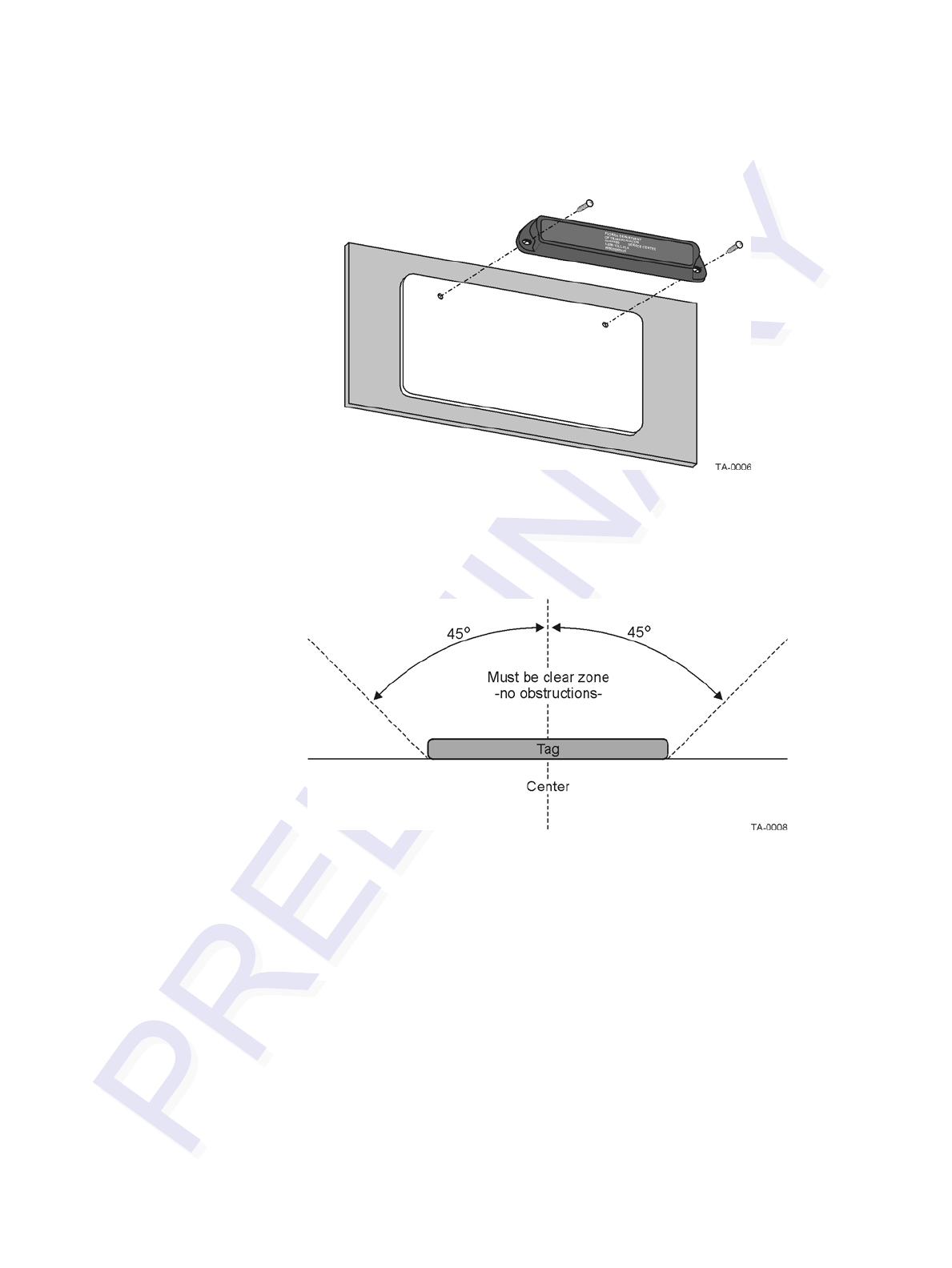
Encompass 4/4800 Multiprotocol Reader System Guide
3-18
Figure 3-15 Upper Placement In License Plate Area
4. Make sure the area within 45 degrees of the center of the tag is free of
obstructions. See Figure 3-16.
Figure 3-16 Obstruction-Free Area
5. Make sure that no material overhangs the tag. If overhang is more than ½ inch
(1.27 cm), insert spacers or washers directly behind the tag so that the tag is clear
of any overhanging obstruction. Secure the bolts with a nut. See Figure 3-17.
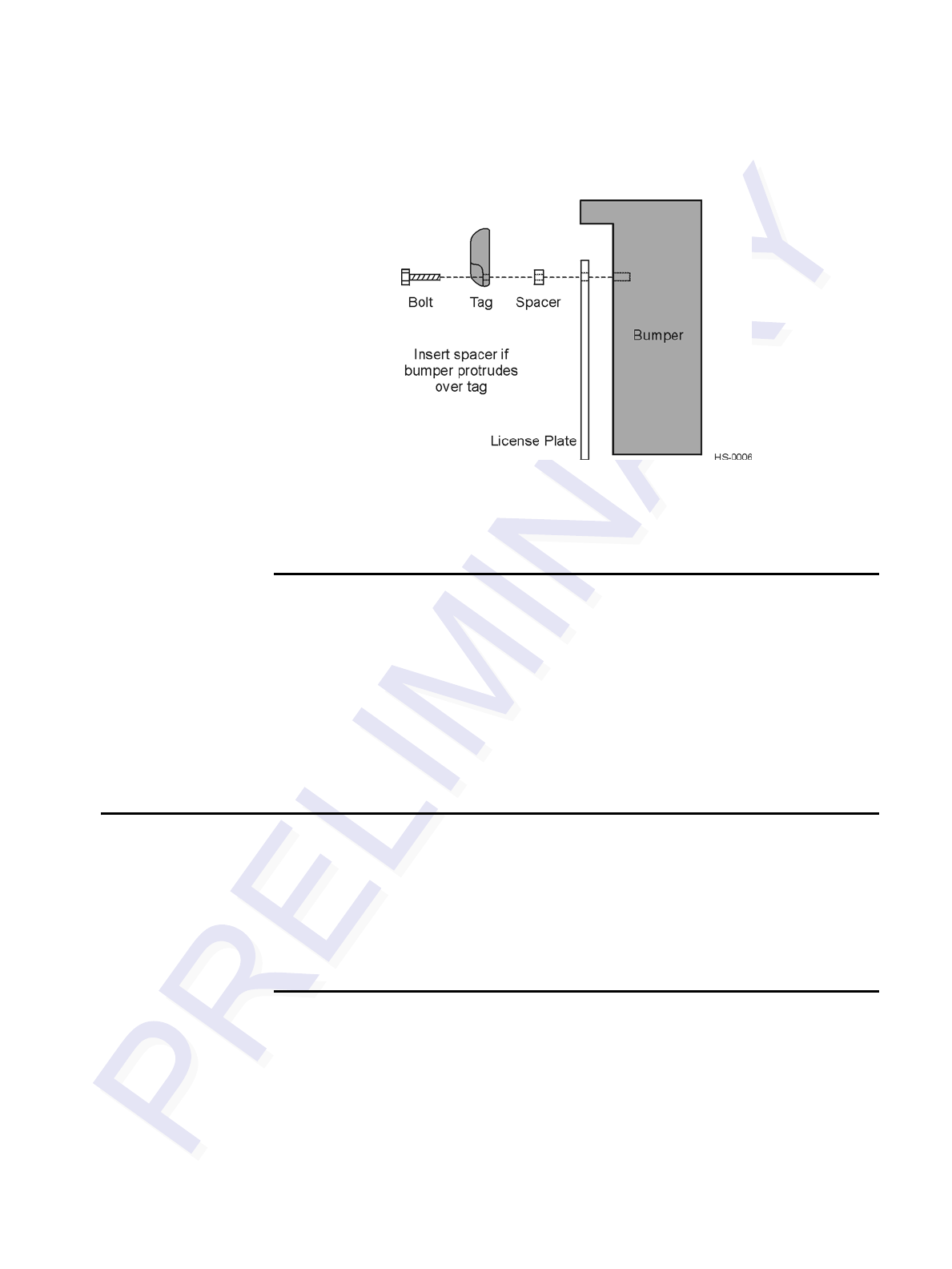
Choosing, Installing, and Removing Tags
3-19
Figure 3-17 Spacer Positioned Behind Tag
6. Tighten the bolts and nuts with a screwdriver and wrench to secure the tag to the
vehicle.
Types of Bumpers
When mounting tags directly to a bumper, consider the following factors:
•Tags can be mounted on any metal or non-metallic surface; composition of
bumper does not matter.
•Tags can be mounted to plastic bumpers using self-threading screws.
•Metal bumpers should be pre-drilled; self-threading screws may be used.
Alternate Mounting Locations
If the exterior type tag cannot be mounted on the license plate bracket or directly on
the bumper, it may be mounted on a relatively vertical front surface of the vehicle. The
exterior tag should be mounted as close to the bumper as possible, following all guide-
lines regarding orientation, obstruction, and overhang given for bumper mounting. For
applications where the integrity of the mounting surface cannot be compromised, the
exterior tag can be mounted on a smooth flat surface using double-sided tape.
Required Materials
Exterior tags need to be installed on a relatively flat surface. You need the following
materials to install exterior tags:
•Rubbing alcohol, 50/50 isopropyl alcohol and water, or solvent/cleaner for metal
•Sponge and dry cloth
•Exterior tag with the double-sided adhesive tape attached

Encompass 4/4800 Multiprotocol Reader System Guide
3-20
Installation Procedures Using Tape
To install the tag on a metal or plastic bumper
1. Clean and degrease the tag installation area of the vehicle bumper with solvent/
cleaner.
2. Dry the area thoroughly using a clean, dry cloth.
3. Remove the backing from the double-sided tape on the back of the tag, as shown
in Figure 3-18.
Figure 3-18 Exterior Tag with Double-Sided Tape
4. Position the tag over the installation area, making sure that the tag and
Encompass 4/4800 Multiprotocol Reader orientation are the same (horizontal or
vertical).
5. Press the tag firmly against the bumper.
Installation Procedures Using Blind Rivets
To install an exterior tag using blind rivets through the tag’s installation
tabs
1. Position the tag on the bumper in the installation area and mark the hole positions
of the tag’s installation tabs on the bumper.
2. Follow the rivet manufacturer’s instructions to drill holes in the bumper for
rivets.
3. If the rivet head is smaller than the tag installation holes and can be pulled
through the holes, use a small washer to secure the rivet through the tag.
Removing Exterior Tags
To remove an exterior tag installed with rivets, follow the rivet manufacturer’s
instructions to remove the rivets.

4
Installing the Encompass 4/4800
Multiprotocol Reader


4-3
Chapter 4
Installing the Encompass 4/4800 Multiprotocol
Reader
This chapter lists the materials needed and presents the procedures to
pre-test and install the EncompassTM 4/4800 Multiprotocol Reader.
Installation Process
After you have developed the site plan and identified the location to install the
Encompass 4/4800 Multiprotocol Reader and antenna1, if required, you are ready to
install the equipment. Installation involves the following tasks:
•Pre-installation testing of Encompass 4/4800 Multiprotocol Reader power and tag
read capability
•Mounting the Encompass 4/4800 Multiprotocol Reader and antenna, if required,
on a pole, ceiling, or wall
•Connecting the antenna
•Connecting the Encompass 4/4800 Multiprotocol Reader power
•Marking the read zone
•Connecting the Encompass 4/4800 Multiprotocol host and sense input/sense out-
put and communications
Materials Supplied by TransCore
You need the following materials to pre-test and install the Encompass 4/4800 Multi-
protocol Reader. TransCore supplies some of the materials; other materials must be
obtained from other sources.
Contents of Shipping Carton
Ensure that you have received all parts before beginning your pre-installation Encom-
pass 4/4800 Multiprotocol Reader tests. Your Encompass 4/4800 Multiprotocol
Reader is packaged with the following materials:
•One Encompass 4/4800 Multiprotocol Reader
1. The Encompass 4/4800 Multiprotocol Reader is designed with an internal patch antenna
or with a RF cable connector for use with an external antenna. Unless noted in the text,
"antenna" refers to an "external antenna."

Encompass 4/4800 Multiprotcol Reader System Guide
4-4
•One mounting bracket and the mounting hardware
•Any accessories ordered as options as shown in Table 4-1
Required accessories are a power/communications cable harness and a 110V AC wall
transformer or a 12V AC to 18V AC step-up transformer. If you are using an antenna
with the Encompass 4, you also require an Encompass 4/4800 Multiprotocol Reader-
compatible antenna and an antenna RF interface. These may be ordered as accessories
from TransCore or obtained from other sources.
Installation Accessory Options
Table 4-1 lists optional TransCore Encompass 4/4800 Multiprotocol Reader installa-
tion accessory items.
Note: The Encompass 4/4800 Multiprotocol Reader may be ordered with a multwire
cable harness (part number 58-1620-001 or 58-1620-002 in Table 4-1) as a separate
accessory. On end has a waterproof connector for the Encompass 4/4800 Multiproto-
col Reader, and the other end has 13 pairs of color-coded wires.
Additional Materials Needed for Testing
You need these additional materials to perform the pre-tests on the Encompass 4/4800
Multiprotocol Reader:
•Two test tags, supplied by the TransCore dealer or distributor
•Suitable 18V AC or 18V DC power wiring for the Encompass 4/4800 Multiproto-
col Reader
•Audible circuit tester and 9V DC battery for circuit tester power
Table 4-1 Installation Accessories
Part No. Description
54-1620-001 Wall or ceiling mount kit
58-1620-001 5-ft connector cable harness
58-1620-002 20-ft connector cable harness
20-1620-003 Connector kit only
56-1620-004 13-pair cable (sold by the foot)
76-1620-005 110V AC to 18V AC Class C transformer
76-1620-006 12V AC to 18V AC step-up transformer
16-xxxx-001 Encompass 4/4800 Multiprotocol Reader System Guide
(this manual)
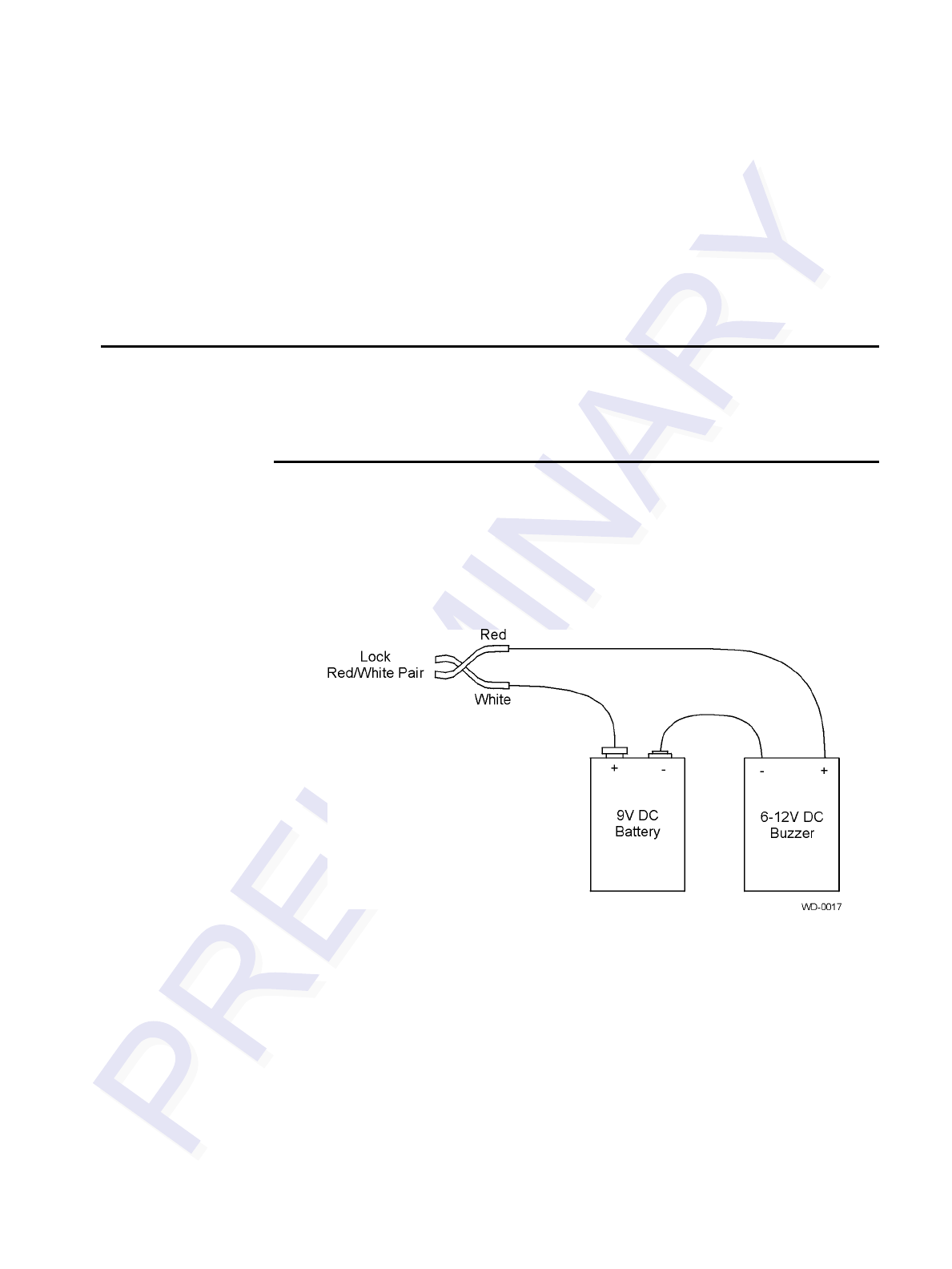
Installing the Encompass 4/4800 Multiprotocol Reader
4-5
•Wire stripper
•One Encompass 4/4800 Multiprotocol Reader-compatible antenna (if required)
•Suitable RF interface coaxial cable (if using antenna)
Pre-installation Testing of the Encompass 4/4800 Multi-
protocol Reader
Before installing the Encompass 4/4800 Multiprotocol Reader permanently at the site,
you should use an audible circuit tester to confirm that the Encompass 4/4800 Multi-
protocol Reader has power and can read a tag presented in the tag read zone.
Testing the Encompass 4/4800 Multiprotocol
Reader Using an Audible Circuit Tester
An audible circuit tester is also called a buzz box. These boxes are available at some
electronic parts supply stores, or you can make a buzz box, as shown in Figure 4-1.
The buzz box is powered by a 9V DC battery and is equipped with two alligator-clip
leads. When you touch the leads together, the box makes an audible sound.
Figure 4-1 Wiring for Audible Circuit Tester
To test the Encompass 4/4800 Multiprotocol Reader that uses an internal antenna,
connect the power supply as described in the appropriate section below, and then test
as described in the section “Bench Testing the Encompass 4/4800 Multiprotocol
Reader Before Installation” on page 4-12.
To test the Encompass 4/4800 Multiprotocol Reader that uses an external antenna,
connect the antenna and connect the power supply as described in the appropriate sec-
tion below, and then test as described in the section “Bench Testing the Encompass 4/
4800 Multiprotocol Reader Before Installation” on page 4-12.
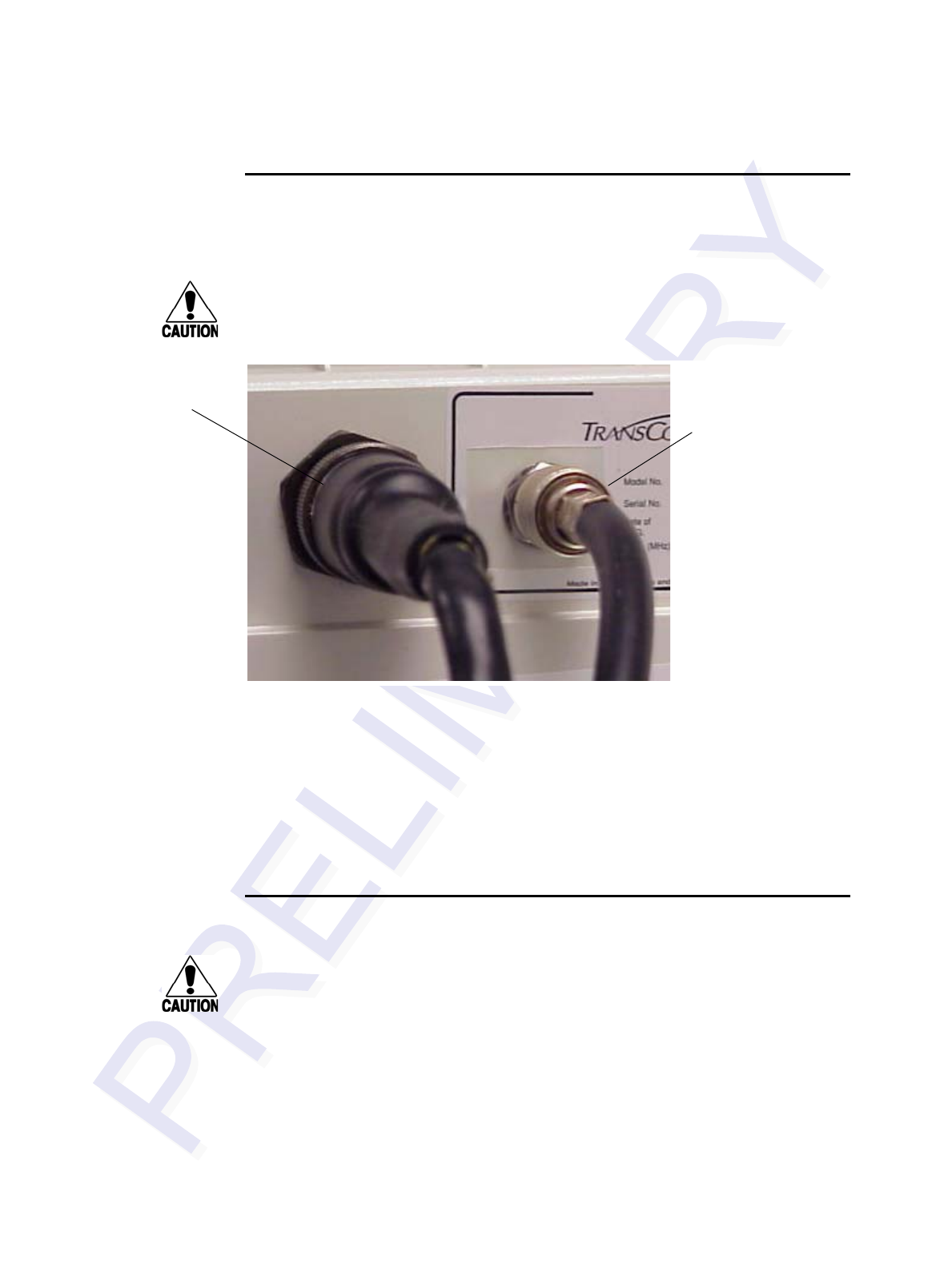
Encompass 4/4800 Multiprotcol Reader System Guide
4-6
Connecting the Antenna
Use these instructions to connect the Encompass 4/4800 Multiprotocol Reader and
antenna.
Caution
To avoid damage to the Encompass 4/4800 Multiprotocol Reader, you must connect
the antenna before applying power to the reader.
Figure 4-2 Back of Encompass 4/4800 Multiprotocol Reader Showing Antenna
Connector
To connect the reader and antenna
1. Ensure the reader is turned off and unplugged.
2. Connect one end of the RF interface cable to the antenna.
3. Connect the other end of the RF interface cable to the antenna connector on the
back of the Encompass 4/4800 Multiprotocol Reader. See Figure 4-1.
Connecting the AC Power Supply
Caution
If you are using an external antenna, to avoid damage to the Encompass 4/4800
Multiprotocol Reader, you must connect the antenna before applying power to the
reader.
To connect the Encompass 4/4800 Multiprotocol Reader to a low-voltage
AC power supply
1. Connect the Encompass 4/4800 Multiprotocol power wires from the cable to the
transformer using the color coding as described in Table 4-2.
Antenna
connector
with RF cable
attached
Power/communica-
tions cable
Installing the Encompass 4/4800 Multiprotocol Reader
4-7
2. Complete the power connections at the power supply.
Connecting the DC Power Supply
To connect the Encompass 4/4800 Multiprotocol Reader to a low-voltage
DC power supply
Caution
If you are using an external antenna, to avoid damage to the Encompass 4/4800
Multiprotocol Reader, you must connect the antenna before applying power to the
reader.
1. Connect the Encompass 4/4800 Multiprotocol Reader power wires from the
cable to the low-voltage terminals using the connection designations shown in
Table 4-3.
Table 4-2 AC Transformer Connections for Colored-Wire Pair Cable
Signal from
Encompass 4
Colored-Wire Pair Cable
Connect to
Transformer
Terminal Strip
Wire Pair from
Encompass
4/4800
Multiprotocol
Reader Cable
Color Used
Main power input Brown/Red and
Orange/Red Orange and
Brown L1
(16 to 20V AC)
Main power return Red and Red L2
(16 to 20V AC)
Table 4-3 Low Voltage DC Cable Connections for the Colored-Wire Pair Cable
Signal from
Encompass 4
Colored-Wire Pair Cable
Connection Use
Wire Pair from
Encompass 4/
4800
Multiprotocol
Reader Cable
Color Used
Main power input Brown/Red and
Orange/Red Orange and
brown 16 to 28V DC+ terminal
Main power return Red and red 16 to 28V DC- terminal

Encompass 4/4800 Multiprotcol Reader System Guide
4-8
Connecting Communications for Bench Testing
TransCore offers reader models that communicate through RS–232, RS–422, and
Wiegand interface protocols. This section describes the procedures and materials
required for connecting the communications to perform pre-installation bench testing
of the Encompass 4/4800 Multiprotocol Reader.
Required Materials
You need the following materials to connect the communications cable to the PC:
•PC or laptop
•Any terminal emulation program such as Procomm Plus™ or Hyper Terminal™
running on a PC
•Communications cable to connect to the COM1 port on your PC
Encompass 4/4800 Multiprotocol Reader communications and customer interface sig-
nals are supplied from the Encompass 4/4800 Multiprotocol Reader to the host
through a multiwire cable, which is a 13-pair pigtail. The connector for this cable is
located on the back of the Encompass 4/4800 Multiprotocol Reader. Refer to the fol-
lowing sections to connect the appropriate communications wires from the cable to
the PC.
These sections contain instructions for connecting RS–232 and RS–422 communica-
tions between the Encompass 4/4800 Multiprotocol Reader and the PC for bench test-
ing purposes. Each section contains wiring instructions and pin assignments followed
by step-by-step connection procedures.
The Encompass 4/4800 Multiprotocol Reader can remain powered up while connect-
ing reader-to-host PC communications.
Connecting for Bench Testing with RS–232 Interface
RS–232 interface signals are supplied by three or five wires from the Encompass 4/
4800 Multiprotocol communications cable. The pin assignments for the signal to the
host male DB9 and DB25 connectors are shown in boldface in Figure 4-15.
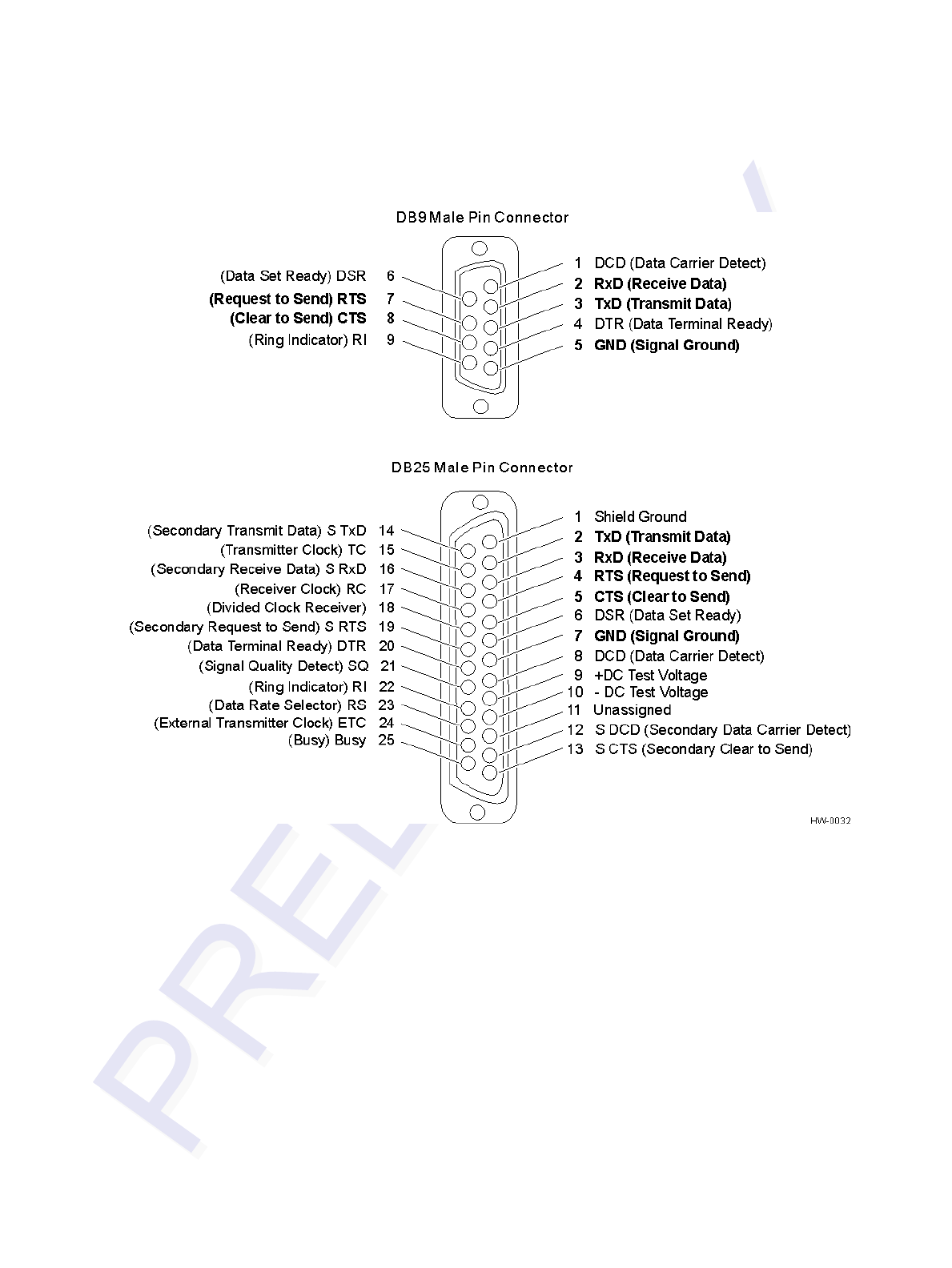

Encompass 4/4800 Multiprotcol Reader System Guide
4-10
Connecting the Encompass 4/4800 Multiprotocol Reader Colored-Wire
Pair Cable
Table 4-7 shows the RS–232 colored wire assignments.
To connect the colored-wire cable using RS–232 interface
1. Connect the black wire (transmit data) from the red and black wire pair to pin 2
of the DB9 connector or pin 3 of the DB25 connector.
2. Connect the red wire (receive data) from the red and black wire pair to pin 3 of
the DB9 connector or pin 2 of the DB25 connector.
Table 4-4 RS–232 Interface Signal Wiring for Colored-Wire Pair Cable
Signal from
Encompass
4/4800
Multiprotocol
Reader
Colored-Wire Pair Cable
Connect
Wire to
Host DB9
Pin
Connect
Wire to
Host DB25
Pin
Wire Pair
from
Encompass
4/4800
Multiprotocol
Reader
Color Used
TxD —
Encompass 4/
4800 Multiprotocol
Reader sense
output, host sense
input
Red/Black Black Pin 2 Pin 3
RxD —
Encompass 4/
4800 Multiprotocol
Reader sense
input, host sense
output
Red Pin 3 Pin 2
Signal ground Yellow/Black Yellow or
Black Pin 5 Pin 7
Optional for hardware handshaking
RTS —
Encompass 4/
4800 Multiprotocol
Reader sense
output, host sense
input
Yellow/Red Yellow Pin 8 Pin 5
CTS —
Encompass 4/
4800 Multiprotocol
Reader sense
input, host sense
output
Red Pin 7 Pin 4

Installing the Encompass 4/4800 Multiprotocol Reader
4-11
3. Connect either the yellow or black wire (signal ground) from the yellow and
black wire pair to pin 5 of the DB9 connector or pin 7 of the DB25 connector.
4. Plug the DB9 connector or DB25 connector into the PC.
If the host is set up for hardware handshaking, use the following procedures:
1. Connect the yellow wire (RTS) from the yellow and red wire pair to pin 8 of the
DB9 connector or pin 5 of the DB25 connector.
2. Connect the red wire (CTS) from the yellow and red wire pair to pin 7 of the DB9
connector or pin 4 of the DB25 connector.
Connecting for Bench Testing with RS–422 Interface
RS–422 interface signals are supplied by four wires from the Encompass 4/4800 Mul-
tiprotocol Reader communications cable. Your host must have an RS–422 interface
with either an internal or external converter.
Note: For temporary bench testing purposes only, you may connect the RS–422 inter-
face signal wires according to Table 4-5. For permanent installations, follow the RS–
422 connection instructions on page 4-27.
Connecting the Encompass 4/4800 Multiprotocol Reader Colored-Wire
Pair Cable for Bench Testing with RS–422 Interface.
Table 4-8 shows the RS–422 signals and their interface wire connectivity for bench
testing purposes only.
Table 4-5 RS–422 Interface Signal Wiring for Bench Testing
Signal from Encompass 4/
4800 Multiprotocol Reader
Colored-Wire Pair Cable
Connect Wire
to Host DB9
Pin
Connect Wire
to Host DB25
Pin
Wire Pair
from
Encompass
4/4800
Multiprotocol
Reader
Color Used
Signal ground Yellow/Red Yellow Pin 5 Pin 7
TxD - Encompass 4/4800
Multiprotocol Reader sense
output, host sense input
Red Pin 2 Pin 3
Signal ground Red/Black Black Pin 5 Pin 7
RxD - Encompass 4/4800
Multiprotocol Reader sense
input, host sense output
Red Pin 3 Pin 2

Encompass 4/4800 Multiprotcol Reader System Guide
4-12
To connect the colored-wire cable for bench testing a reader with RS–
422 interface
1. Connect the yellow wire (signal ground) from the yellow and red wire pair to the
host DB9 Pin 5 or Host DB25 Pin 7.
2. Connect the red wire (transmit) from the yellow and red wire pair to the host
DB9 Pin 2 or Host DB25 Pin 3.
3. Connect the black wire (signal ground) from the red and black wire pair to the
host DB9 Pin 5 or Host DB25 Pin 7.
4. Connect the red wire (receive) from the red and black wire pair to the host DB9
Pin 3 or Host DB25 Pin 2.
Bench Testing the Encompass 4/4800 Multiproto-
col Reader Before Installation
The Encompass 4/4800 Multiprotocol Reader factory default tag read protocol is
IATA tag read mode. Initially the Encompass 4/4800 Multiprotocol Reader reads only
Intellitag-based eGo tags and ignores ATA tags. For more information, see “47N
Select Tag Mode**” on page 7-15.
Note: Test tags should be eGo Windshield Sticker Tags affixed to a piece of nonmetal-
lic windshield-type glass 0.190 to 0.230 inches (4.82 to 5.84 mm) in thickness. The
eGo Windshield Sticker Tag has a reduced read range when not attached to glass.
To test that the Encompass 4/4800 Multiprotocol Reader has power and
can read a tag presented in the read zone
1. Confirm that the Encompass 4/4800 Multiprotocol Reader colored-wire pair
cable is correctly connected to a suitable AC or DC low-voltage power supply as
discussed on page 4-6 and page 4-7 and that the transformer is connected to a
power outlet.
If you are using an external antenna, confirm that the antenna is connected to the
Encompass 4/4800 Multiprotocol Reader.
Caution
To avoid damage to the Encompass 4/4800 Multiprotocol Reader, you must connect
the antenna before applying power to the reader.
2. Confirm that the Encompass 4/4800 Multiprotocol Reader colored-wire pair
cable communications are connected correctly as described in the section
“Connecting Communications for Bench Testing” on page 4-8.
3. Connect the two leads from the audible circuit tester to the white and red wire
pair (pair #8, lock/lock return) from the Encompass 4/4800 Multiprotocol Reader
power/communications cable.

Installing the Encompass 4/4800 Multiprotocol Reader
4-13
4. Start the terminal emulation application Microsoft HyperTerminal by selecting
Programs>Accessories>Communications>HyperTerminal and press
ENTER.
5. In the HyperTerminal dialog boxes choose the com port to which the
communications interface is attached and set the properties as:
• Bits per second: 9600 baud
• Data bits: 8
• Parity: none
• Stop bits: 1
• Flow control: none
6. Cycle the power on the Encompass 4/4800 Multiprotocol Reader and ensure that
the sign-on message displays.
7. Input the following commands in the order provided in Table 4-6. Commands
include those to switch to command mode, set operational mode, turn on RF, and
return the reader to data mode.
8. Pass an eGo Windshield Sticker Tag in front of the Encompass 4/4800
Multiprotocol Reader or antenna. The audible circuit tester should sound a tone
when the tag is read. If no tone sounds, ensure that steps 1,through 5 were
performed correctly and that you are using a compatible tag. Repeat steps 6 and
7. If no tone sounds, contact TransCore (see “Technical Support” on page 9-7).
9. Disconnect the circuit tester from the Encompass 4/4800 Multiprotocol Reader
power/communications cable.
10. Disconnect the power and communications connections made for pre-installation
testing.
Note: You will need the audible circuit tester again to determine the read zone when
installing the Encompass 4/4800 Multiprotocol Reader at the site.
Table 4-6 Commands for Bench Testing
Entry Reader Response Notes
#01 <CR> #Done <CR/LF> Switches Encompass 4/
4800 Multiprotocol
Reader to command
mode.
#470 #Done <CR/LF> Sets operational mode to
Dual (1) - Read eATA
data from Intellitag-based
tags and read ATA tags
#6401 #Done <CR/LF> Turns on RF channel.
#00 <CR> #Done <CR/LF> Returns Encompass 4/
4800 Multiprotocol
Reader to data mode.

Encompass 4/4800 Multiprotcol Reader System Guide
4-14
Mounting the Encompass 4/4800 Multiprotocol Reader
on Round Pole or Flat Surface
This section lists procedures and materials required for mounting the Encompass 4/
4800 Multiprotocol Reader on a round pole or on a ceiling, wall, or other flat surface
based on the site’s requirements.
In permanent installations using an antenna, the Encompass 4/4800 Multiprotocol
Reader should be positioned as close as possible to the antenna. Long cable runs
increase system sensitivity to noise. See Table 2-6 on page 2-20 for maximum RF
cable lengths.
Mounting the Encompass 4/4800 Multiprotocol
Reader on a Round Pole
The Encompass 4/4800 Multiprotocol Reader can be simply and inexpensively
mounted on a round pole. The pole must be a minimum of 2 inches (5 cm) in diameter
and should extend approximately 8 feet (2.4 m) above the pavement level. The pole
must be installed according to local building codes.
Required Materials
You need the following supplies to mount the Encompass 4/4800 Multiprotocol
Reader on a round pole:
•A 5/32-inch Allen wrench to assemble and adjust the mounting brackets
•Two 0.5 inch (1.3 cm) wide, stainless steel hose clamp straps that are 12 inches
(30.5 cm) long for a typical 2-inch (5-cm) diameter pole or 24 inches (61 cm) long
for a 10-inch (25-cm) diameter pole
•Flat-tip screwdriver or adjustable wrench to tighten hose clamp straps
Procedures
To mount the Encompass 4/4800 Multiprotocol Reader to a pole
1. Unpack the Encompass 4/4800 Multiprotocol Reader. A factory-mounted bracket
(Figures 4-2 and 4-3) is attached to the back of the Encompass 4/4800
Multiprotocol Reader. A pole mount bracket assembly (Figure 4-6) is bubble-
wrapped separately and contains a plastic bag of four Allen screws and washers.
2. Using the two 0.5 inch (1.3 cm) stainless steel hose clamps, attach the pole mount
bracket assembly to the pole approximately 8 feet (2.4m) above the pavement
surface. Tighten slightly so you can adjust the Encompass 4/4800 Multiprotocol
Reader left or right, but not so slightly the straps slide down the pole.
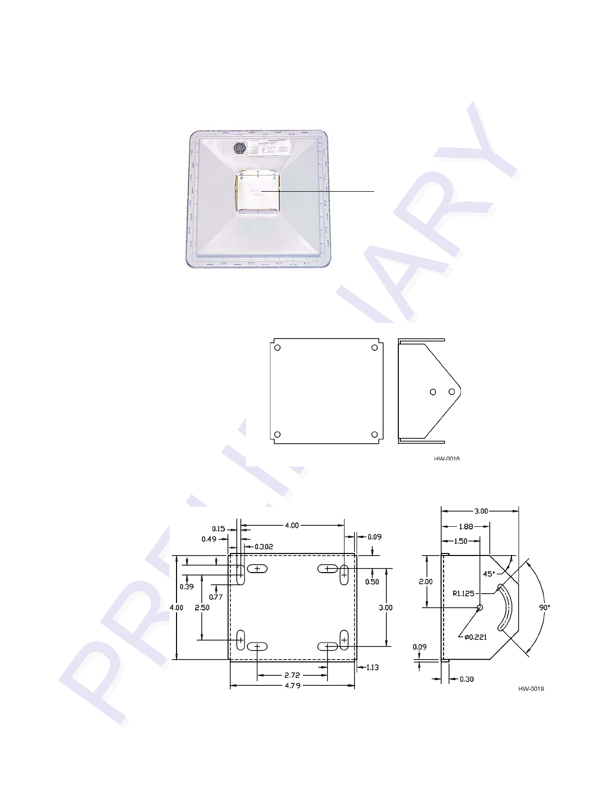
Installing the Encompass 4/4800 Multiprotocol Reader
4-15
Figure 4-4 Back of the Encompass 4/4800 Multiprotocol Reader
Figure 4-5 Factory-Mounted Bracket
Figure 4-6 Pole-Mount Bracket Assembly
Factory-mounted bracket
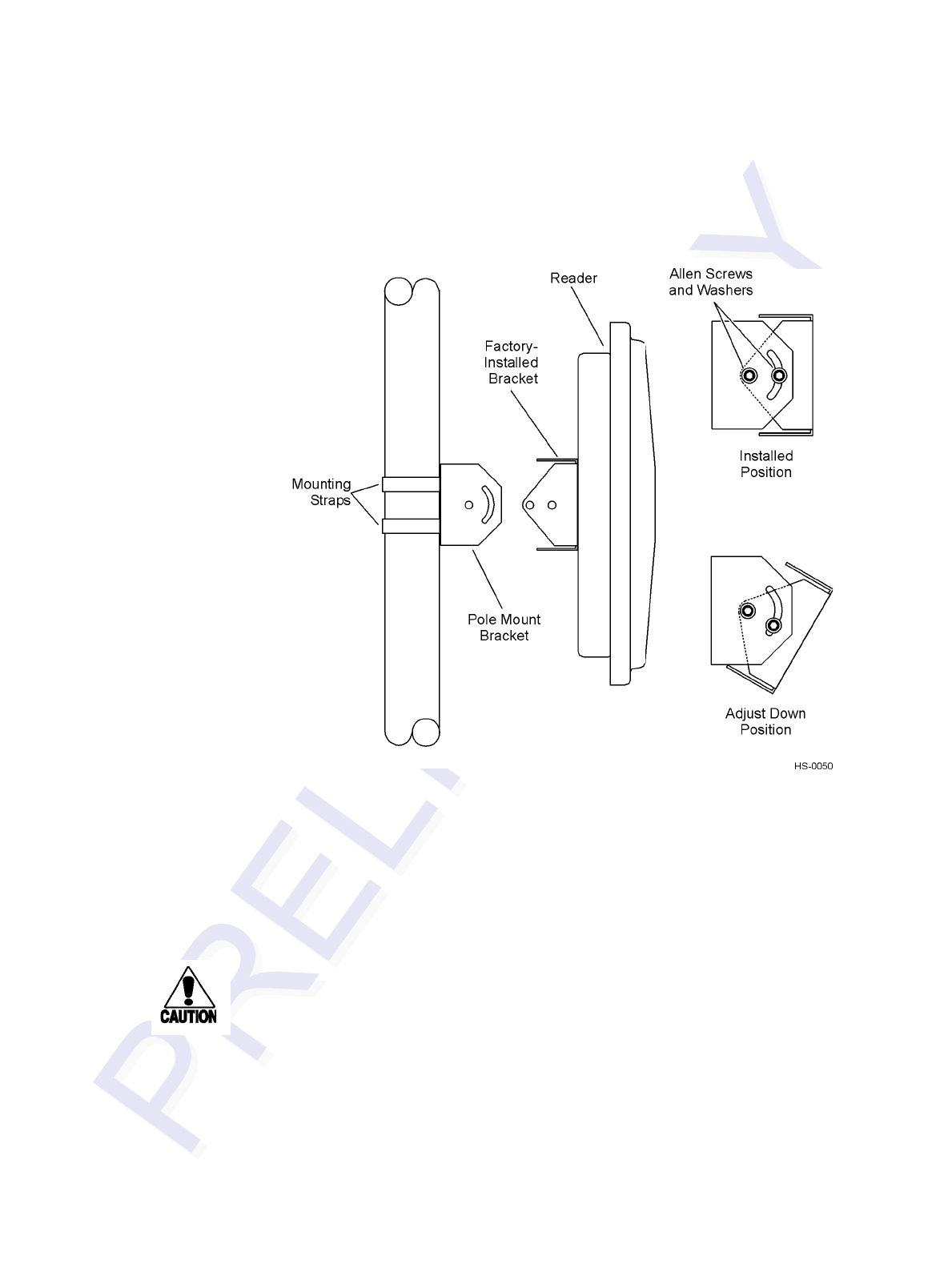
Encompass 4/4800 Multiprotcol Reader System Guide
4-16
3. Using the four Allen screws and washers, attach the Encompass 4/4800
Multiprotocol Reader to the pole mount bracket as shown in Figure 4-7. Tighten
the screws slightly so that the Encompass 4/4800 Multiprotocol Reader can be
adjusted up or down, but not so slightly the mounting assembly slips.
Figure 4-7 The Encompass 4/4800 Multiprotocol Reader Attached to the Pole
Mount Bracket
4. Adjust the assembly by pointing the Encompass 4/4800 Multiprotocol Reader to
the middle of the area where tags will be read, and tighten all screws and straps
slightly.
Note: Adjust the Encompass 4/4800 Multiprotocol Reader to provide the most
direct line of sight to the tags.
Figure 4-8 illustrates front and top views of a pole-mounted Encompass 4/4800 Multi-
protocol Reader with the approximate measurements for sites where tags would be
mounted on the interior driver-side windshield. eGo Windshield Sticker Tags may be
mounted on the interior upper center or upper corner of the windshield.
Note: Determine the read zone before you tighten all screws and straps permanently.
Refer to the section “Marking the Read Zone” on page 4-32.
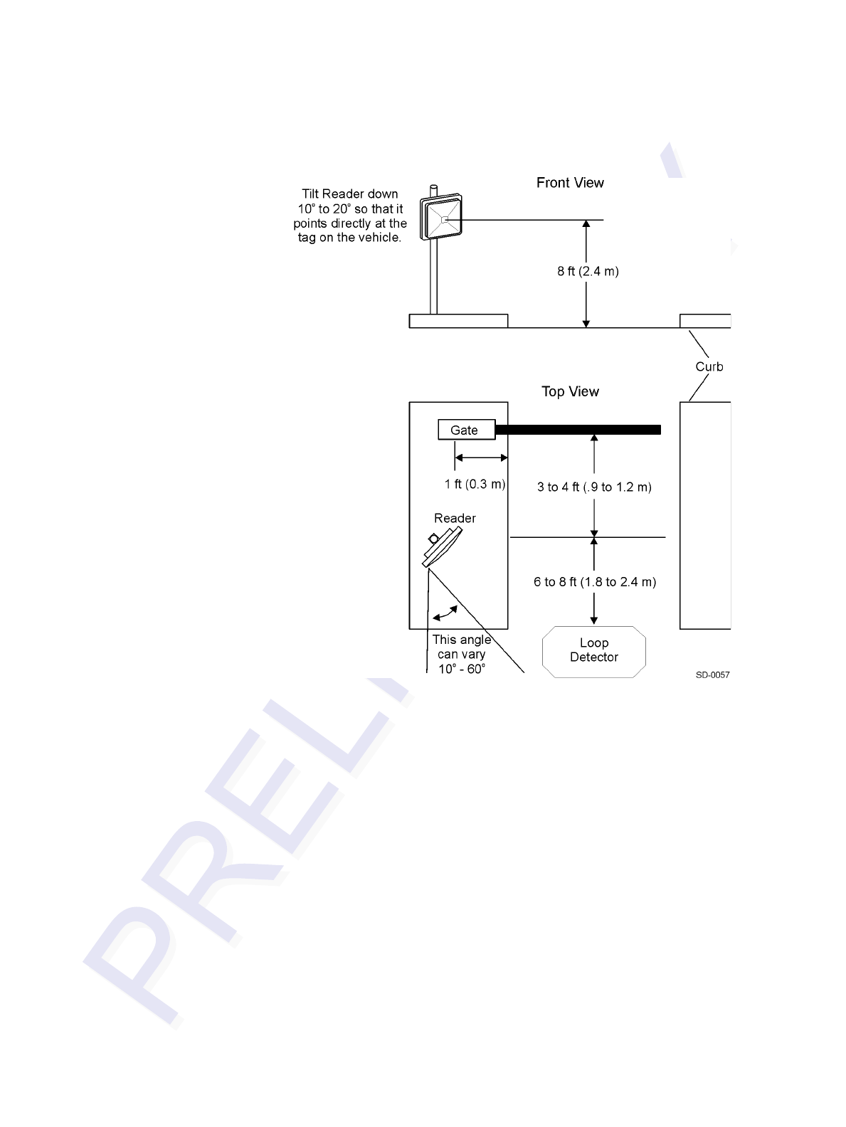
Installing the Encompass 4/4800 Multiprotocol Reader
4-17
Figure 4-8 Front and Top Views of the Encompass 4/4800 Multiprotocol Reader
Position
Note: The dimensions in Figure 4-8 are for demonstration purposes only and are
approximations for sites using the older ATA-type tags. Actual dimensions vary as
lane geometry and tag style varies from site to site. Adjust the Encompass 4/4800 Mul-
tiprotocol Reader matching site and tag mounting positions to provide the most direct
line of sight to the tags.
Caution
Connect the reader bracket to earth ground using a ground cable and stake.
TransCore recommends that you follow the National Electric Code for lightning
protection for the locale where you are installing the Encompass 4/4800 Multiproto-
col Reader.
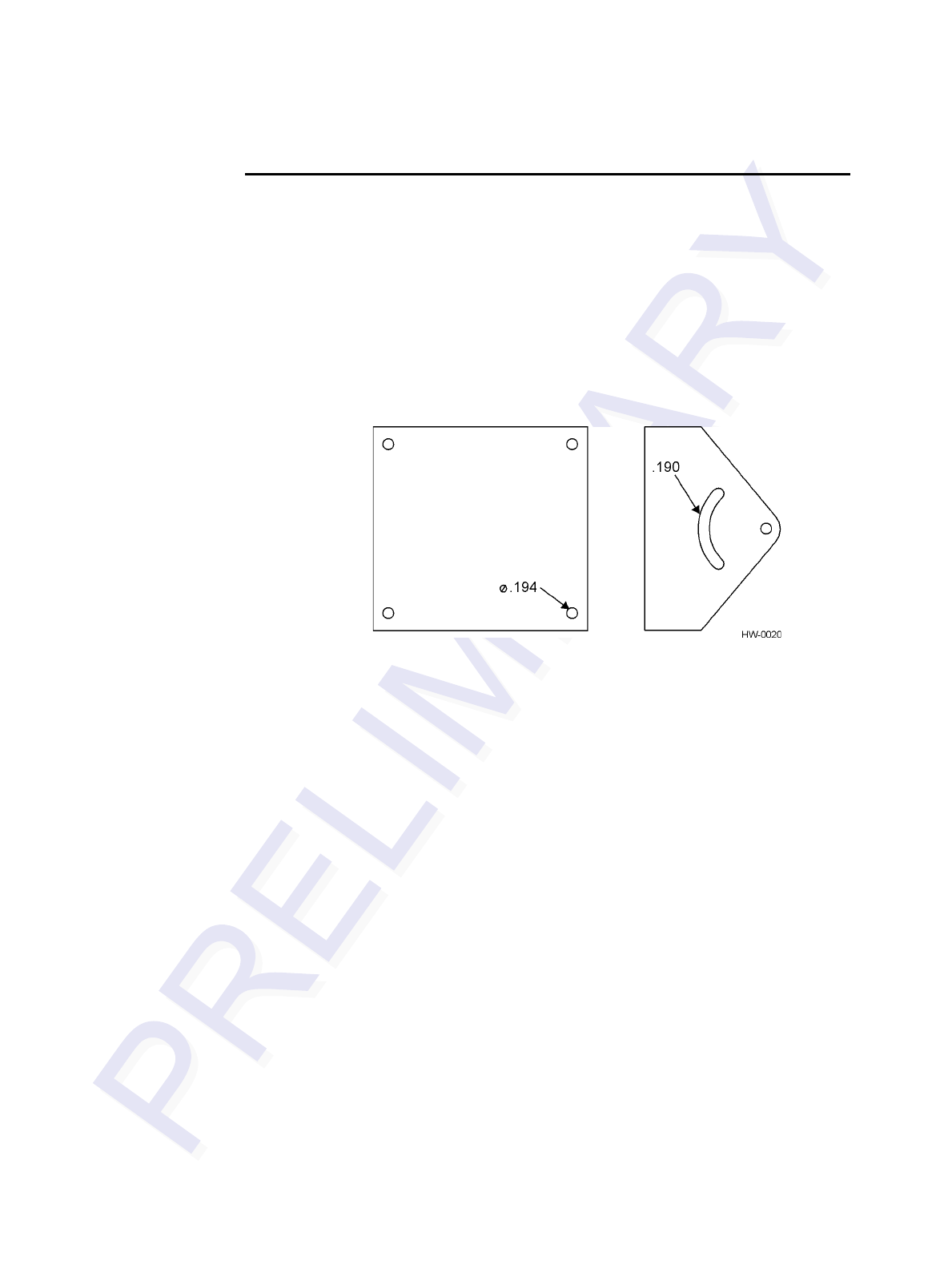
Encompass 4/4800 Multiprotcol Reader System Guide
4-18
Mounting the Encompass 4/4800 Multiprotocol
Reader to a Wall or Flat Surface
The basic Encompass 4/4800 Multiprotocol Reader is supplied with a pole-mount
bracket assembly (Figure 4-6) that allows you to adjust the Encompass 4/4800 Multi-
protocol Reader up and down. TransCore recommends using the wall-mount bracket
accessory kit (Figure 4-9) in addition to the pole-mount bracket to provide additional
horizontal aiming flexibility when attaching the Encompass 4/4800 Multiprotocol
Reader to a pole with flat sides or to a wall or ceiling where other structures can inter-
fere with accurately aiming the Encompass 4/4800 Multiprotocol Reader toward the
tags.
Figure 4-9 Wall Mount Bracket Accessory (part number 54-1620-001)
Required Materials
You need the following materials to install the Encompass 4/4800 Multiprotocol
Reader on a wall or flat surface. Ensure the use of high-quality, corrosion-resistant
anchor hardware.
•Anchor hardware suitable for the surface on which you mount the Encompass 4/
4800 Multiprotocol Reader
Because the Encompass 4/4800 Multiprotocol Reader weighs only 9 1/2 lbs (4.3
kg), 0.25 in (0.6 cm) bolt hardware is adequate to secure the unit to a wall or
ceiling.
•Four hex nuts 3/8-16 threaded and four lockwashers
•5/32-inch Allen wrench
•One Encompass 4/4800 Multiprotocol wall mount bracket accessory kit (required)
Procedures
To mount the Encompass 4/4800 Multiprotocol Reader to a wall or ceiling
1. Unpack the Encompass 4/4800 Multiprotocol Reader. Set aside the pole mount
bracket.
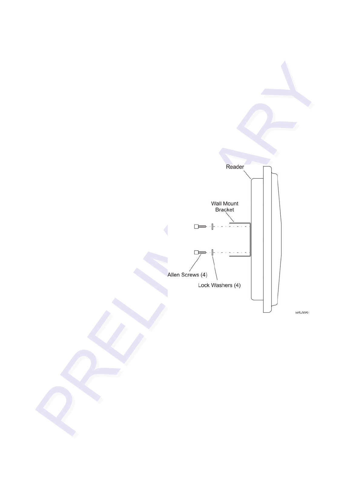
Installing the Encompass 4/4800 Multiprotocol Reader
4-19
Use the bracket in the remaining steps to provide greater adjustment for the
Encompass 4/4800 Multiprotocol Reader. The pole-mount bracket is wrapped
separately from the Encompass 4/4800 Multiprotocol Reader and contains a
plastic bag of four Allen screws and washers.
2. Using the 5/32-inch Allen wrench, remove the factory-mounted bracket attached
to the back of the Encompass 4/4800 Multiprotocol Reader. Remove all four
Allen screws and lock washers from the bracket and set aside.
3. Unpack the wall-mount bracket accessory kit.
4. Using the Allen screws and lock washers set aside in Step 2, attach the wall-
mount bracket to the back of the Encompass 4/4800 Multiprotocol Reader, as
shown in Figure 4-10.
Figure 4-10 Wall Mount Bracket Attached to the Encompass 4/4800
Multiprotocol Reader
5. Tighten the screws to secure the bracket.
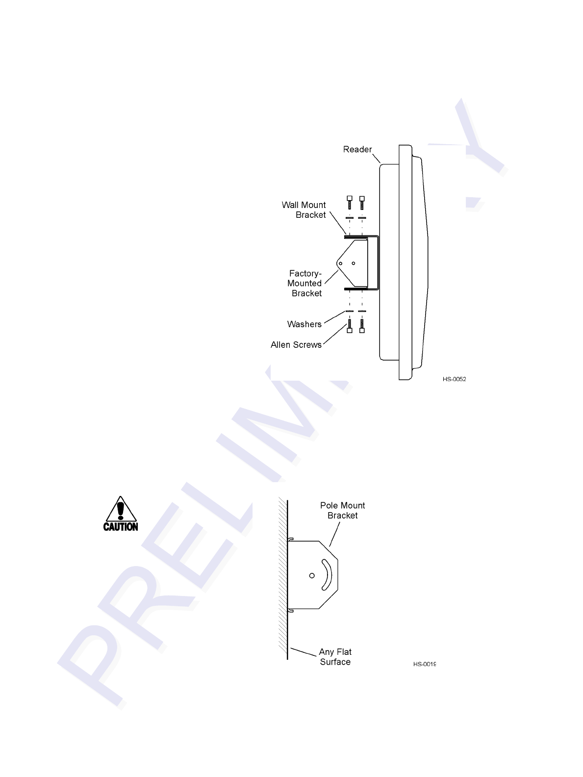
Encompass 4/4800 Multiprotcol Reader System Guide
4-20
6. Using the four screws and washers supplied with the wall-mount bracket, attach
the factory-mounted bracket to the wall mount bracket, lining up the four outside
screw holes as shown in Figure 4-11.
Figure 4-11 Factory-Mounted Bracket Attached to Wall Mount Bracket
7. Tighten lightly, since you will want to adjust the bracket later. This subassembly
allows you to aim the Encompass 4/4800 Multiprotocol Reader left or right when
all three brackets are assembled.
8. Mount the pole-mount bracket to the wall, ceiling, or fixture using appropriate
anchors as shown in Figure 4-12.
Figure 4-12 Pole Mount Bracket Attached to Wall
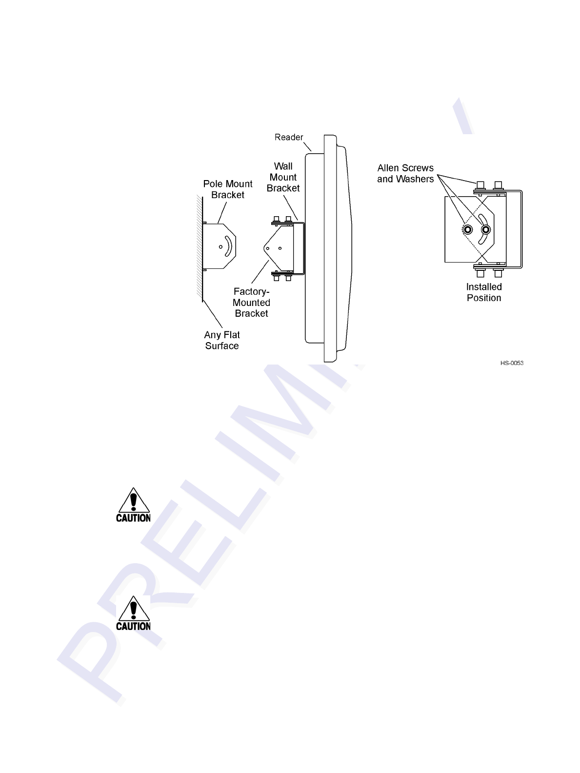
Installing the Encompass 4/4800 Multiprotocol Reader
4-21
9. Mount the Encompass 4/4800 Multiprotocol Reader to the pole-mount bracket
using Allen screws, as shown in Figure 4-13.
Figure 4-13 Connecting the Encompass 4/4800 Multiprotocol Assembly to Pole
Mount Bracket
10. Adjust the assembly by pointing the Encompass 4/4800 Multiprotocol Reader to
the middle of the area where tags will be read and tighten all screws and straps
slightly.
Note: Adjust the Encompass 4/4800 Multiprotocol Reader to provide the most direct
line of sight to the tags.
Caution
Connect the reader bracket to earth ground using a ground cable and stake.
TransCore recommends that you follow the National Electric Code for lightning
protection for the locale where you are installing the Encompass 4/4800 Multiproto-
col Reader.
After mounting the Encompass 4/4800 Multiprotocol Reader, you must connect it to a
dedicated 16 to 20V AC or 16 to 28V DC power supply.
Caution
To avoid damage to the Encompass 4/4800 Multiprotocol Reader, you must connect
the antenna before applying power to the reader.

Encompass 4/4800 Multiprotcol Reader System Guide
4-22
Mounting the Antenna
If you are using the Encompass4/4800 Multiprotocol Reader that requires an external
antenna in permanent installations, the antenna should be positioned as close as possi-
ble to the Encompass 4/4800 Multiprotocol Reader. Long cable runs increase system
sensitivity to noise. See Table 2-6 on page 2-20 for maximum RF cable lengths.
This section provides guidelines for mounting antennas.
Mounting the Antenna Curb-Side
Some site designs, for example those with curb-side antennas, require that the antenna
be mounted on a round pole. The pole must be a minimum of 2 inches (5 cm) in diam-
eter and should extend approximately 8 feet (2.4 m) above the pavement level. The
pole must be installed according to local building codes.
Procedures
Use the following guidelines to mount an antenna on a curb-side round pole.
To mount the antenna to a curb-side pole
1. Follow the manufacturer’s directions to attach the antenna assembly to the pole
approximately 8 feet (2.4m) above the pavement surface.
2. Tighten slightly so that you can adjust the antenna left or right but not so slightly
that the antenna slides down the pole.
3. Adjust the assembly by pointing the antenna to the middle of the area where tags
will be read, and while in this position, tighten all screws and fastenings slightly.
Note: Adjust the antenna to provide the most direct line of sight to the tags.
Figure 4-14 illustrates front and top views of a pole-mounted antenna with the approx-
imate measurements for sites where tags would be mounted on the interior driver-side
windshield. eGo Windshield Sticker Tags may be mounted on the interior upper center
or upper driver-side corner of the windshield.
Note: Determine the read zone before you tighten all screws and straps permanently.
Refer to the section “Marking the Read Zone” on page 4-32.
After mounting the antenna, you must connect it to the Encompass 4/4800 Multiproto-
col Reader. Follow the procedures described previously in the section “Connecting the
Antenna” on page 4-6.
Caution
To avoid damage to the Encompass 4/4800 Multiprotocol Reader, you must connect
the antenna before applying power to the reader.
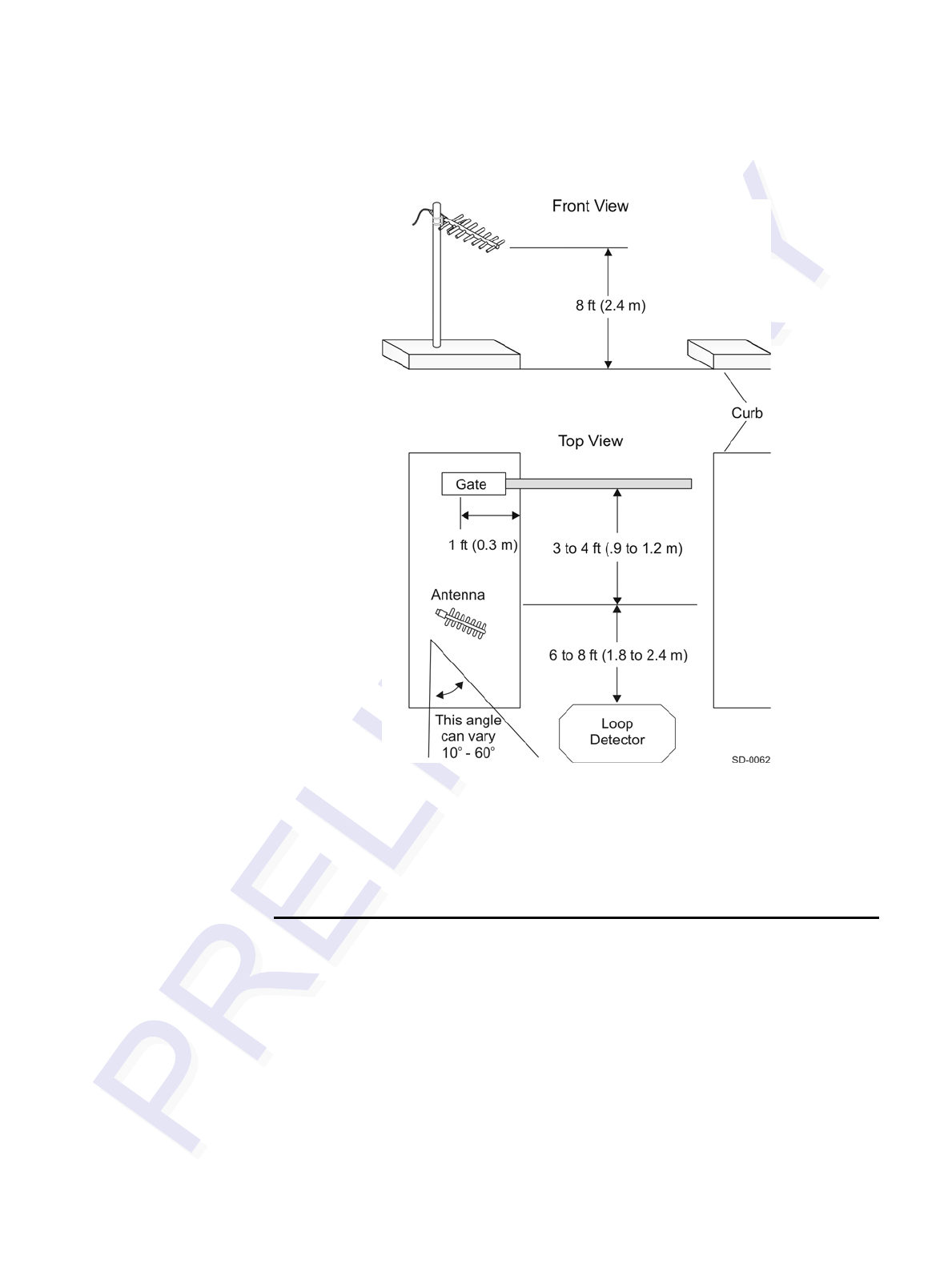
Installing the Encompass 4/4800 Multiprotocol Reader
4-23
Figure 4-14 Front and Top Views of the Curb-Side Antenna Position
Note: The dimensions in Figure 4-14 are for demonstration purposes only and are
approximations for sites using the older ATA-type tags. Actual dimensions vary as
lane geometry and tag style varies from site to site. Adjust the antenna to match site
and tag mounting positions to provide the most direct line of sight to the tags.
Mounting the Antenna Overhead
Some site designs require that the antenna be mounted in an overhead location.
Procedures
To mount the antenna in an overhead location
1. Follow the manufacturer’s directions to attach the antenna assembly to the
overhead location at approximately 18 feet above the pavement surface.
2. Tighten slightly so that you can adjust the antenna up and down but not so
slightly that there is a risk of the antenna falling.
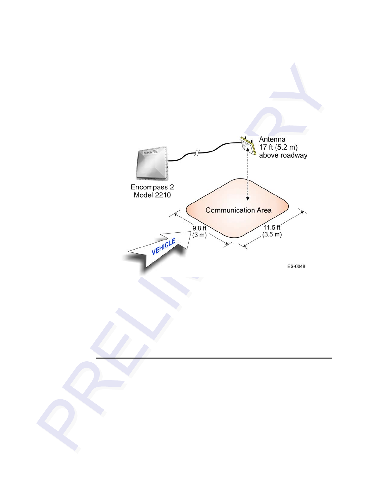
Encompass 4/4800 Multiprotcol Reader System Guide
4-24
3. Adjust the assembly by pointing the antenna to the middle of the area where tags
will be read, and while in this position, tighten all screws and fastenings slightly.
Note: Adjust the antenna to provide the most direct line of sight to the tags.
For example, in toll lanes the Universal Toll Antenna (UTA) would be installed
approximately 15 degrees from the verticle.
Figure 4-15 illustrates an overhead-mounted antenna with approximate measurements
for the read zone.
Figure 4-15 Encompass 4/4800 Multiprotocol Reader Installation with Overhead
Antenna
Note: Determine the read zone before you tighten all screws and straps permanently.
Refer to the section “Marking the Read Zone” on page 4-32.
After mounting the antenna, you must connect it to the Encompass 4/4800 Multiproto-
col Reader. Follow the procedures described previously in the section “Connecting the
Antenna” on page 4-6.
Connecting the Power Supply
To connect the Encompass 4/4800 Multiprotocol Reader to a low-voltage AC power
supply follow the procedures described previously in the section “Connecting the AC
Power Supply” on page 4-6.
To connect the Encompass 4/4800 Multiprotocol Reader to a low-voltage DC power
supply follow the procedures described previously in the section “Connecting the DC
Power Supply” on page 4-7.
After mounting the Encompass 4/4800 Multiprotocol Reader and antenna, if required,
you must connect the reader to a dedicated 16 to 20V AC or 16 to 28V DC power sup-
ply.

Installing the Encompass 4/4800 Multiprotocol Reader
4-25
Caution
To avoid damage to the Encompass 4/4800 Multiprotocol Reader, you must connect
the antenna before applying power to the reader.
Connecting Communications
TransCore offers reader models that communicate through RS–232, RS–422, and
Wiegand interface protocols. This section describes the procedures and materials
required for connecting the communications to the junction box and to the sense input
and sense output circuits.
Required Materials
You need the following materials to connect the communications cable to the PC:
•PC or laptop
•Any terminal emulation program such as Procomm Plus™ or Hyper Terminal™
running on a PC
•Communications cable to connect to the COM1 port on your PC
Connecting the Encompass 4/4800 Multiprotocol
Reader to the PC
Encompass 4/4800 Multiprotocol Reader communications and customer interface sig-
nals are supplied from the Encompass 4/4800 Multiprotocol Reader to the host
through a multiwire cable, which is a 13-pair pigtail. The connector for this cable is
located on the back of the Encompass 4/4800 Multiprotocol Reader. Refer to the fol-
lowing sections to connect the appropriate communications wires from the cable to
the terminal strip that is located inside the junction box.
These sections contain instructions for connecting RS–232, RS–422, and Wiegand
communications between the Encompass 4/4800 Multiprotocol Reader and the PC.
Each section contains wiring instructions and pin assignments followed by step-by-
step connection procedures.
The Encompass 4/4800 Multiprotocol Reader can remain powered up while connect-
ing reader-to-host PC communications.
RS–232 Interface
RS–232 interface signals are supplied by three or five wires from the Encompass 4/
4800 Multiprotocol Reader communications cable. The pin assignments for the signal
to the host male DB9 and DB25 connectors are shown in boldface in Figure 4-3.

Encompass 4/4800 Multiprotcol Reader System Guide
4-26
Connecting the Encompass 4/4800 Multiprotocol Reader Colored-Wire
Pair Cable
Table 4-7 shows the RS–232 colored wire assignments.
To connect the colored-wire cable using RS–232 interface
1. Connect the black wire (transmit data) from the red and black wire pair to pin 2
of the DB9 connector or pin 3 of the DB25 connector.
2. Connect the red wire (receive data) from the red and black wire pair to pin 3 of
the DB9 connector or pin 2 of the DB25 connector.
Table 4-7 RS–232 Interface Signal Wiring for Colored-Wire Pair Cable
Signal from
Encompass 4/
4800
Multiprotocol
Reader
Colored-Wire Pair Cable
Connect
Wire to
Host DB9
Pin
Connect
Wire to
Host DB25
Pin
Wire Pair
from
Encompass
4/4800
Multiprotocol
Reader
Color Used
TxD —
Encompass 4/
4800 Multiprotocol
Reader sense
output, host sense
input
Red/Black Black Pin 2 Pin 3
RxD —
Encompass 4/
4800 Multiprotocol
Reader sense
input, host sense
output
Red Pin 3 Pin 2
Signal ground Yellow/Black Yellow or
Black Pin 5 Pin 7
Optional for hardware handshaking
RTS —
Encompass 4/
4800 Multiprotocol
Reader sense
output, host sense
input
Yellow/Red Yellow Pin 8 Pin 5
CTS —
Encompass 4/
4800 Multiprotocol
Reader sense
input, host sense
output
Red Pin 7 Pin 4

Installing the Encompass 4/4800 Multiprotocol Reader
4-27
3. Connect either the yellow or black wire (signal ground) from the yellow and
black wire pair to pin 5 of the DB9 connector or pin 7 of the DB25 connector.
4. Plug the DB9 connector or DB25 connector into the PC.
If the host is set up for hardware handshaking, use the following procedures:
1. Connect the yellow wire (RTS) from the yellow and red wire pair to pin 8 of the
DB9 connector or pin 5 of the DB25 connector.
2. Connect the red wire (CTS) from the yellow and red wire pair to pin 7 of the DB9
connector or pin 4 of the DB25 connector.
RS–422 Interface
RS–422 interface signals are supplied by four wires from the Encompass 4/4800 Mul-
tiprotocol Reader communications cable. Your host must have an RS–422 interface
with either an internal or external converter.
Table 4-8 shows the RS–422 signals and their interface wires.
To connect the colored-wire cable using RS–422 interface
1. Connect the yellow wire (transmit +) from the yellow and red wire pair to the
host receive (+) signal.
2. Connect the red wire (transmit –) from the yellow and red wire pair to the host
receive (–) signal.
3. Connect the black wire (receive +) from the red and black wire pair to the host
transmit (+) signal.
4. Connect the red wire (receive –) from the red and black wire pair to the host
transmit (–) signal.
Table 4-8 RS–422 Interface Signal Wiring for Colored-Wire Pair Cable
Signal from Encompass 4/
4800 Multiprotocol Reader
Colored-Wire Pair Cable
Connect to
Signal from
Host
Wire Pair
from
Encompass
4/4800
Multiprotocol
Reader
Color Used
RS–422 Transmit positive Yellow/Red Yellow Receive (+)
RS–422 Transmit negative Red Receive (–)
RS–422 Receive positive Red/Black Black Transmit (+)
RS–422 Receive negative Red Transmit (–)
Signal Ground Yellow/Black Yellow or
Black Signal Ground
Encompass 4/4800 Multiprotcol Reader System Guide
4-28
Wiegand Interface
Wiegand interface signals are supplied by three wires from the Encompass 4/4800
Multiprotocol Reader communications cable. The Encompass 4/4800 Multiprotocol
Reader with RS–232 or RS–422 comes with the Wiegand option built in. The Wie-
gand interface can only be used by the reader to output valid Wiegand tag reads. All
reader commands and responses are issued through the serial interface.
Table 4-9 shows the Wiegand signals and the interface wires.
To connect Wiegand interface
1. Connect the blue wire (data0) from the blue and red wire pair to the data0 wire of
the Wiegand device.
2. Connect the red wire (data1) from the blue and red wire pair to the data1 wire of
the Wiegand device.
3. Connect either the yellow or black wire from the yellow and black pair to the
Wiegand device’s signal ground.
Note: The RS–232 or RS–422 interface is still included on the Encompass 4/
4800 Multiprotocol Reader even when you use the Wiegand configuration. If
serial communication is not needed, TransCore recommends leaving the DB9 or
DB25 connected to the cable for future use.
Warning
Do not cut the RS–232 red/black wires. If you cut the wires, you may not be able to
use them in the future for testing, setting frequency, or adding additional functions.
Connecting Sense Input and Sense Output Circuits
The Encompass 4/4800 Multiprotocol Reader has two sense input circuits and three
sense output circuits available. The sense input circuits can be used to notify the
Encompass 4/4800 Multiprotocol Reader of external events and are designed to be
Table 4-9 Wiegand Interface Signal Wiring for Colored-Wire Pair Cable
Signal from Encompass
4/4800 Multiprotocol
Reader
Colored-Wire Pair Cable
Connect to
Signal from
Host
Wire Pair
from
Encompass
4/4800
Multiprotocol
Reader
Color Used
Wiegand Zero Output Blue/Red Blue Data0
Wiegand One Output Red Data1
Signal Ground Yellow/Black Yellow or black Ground
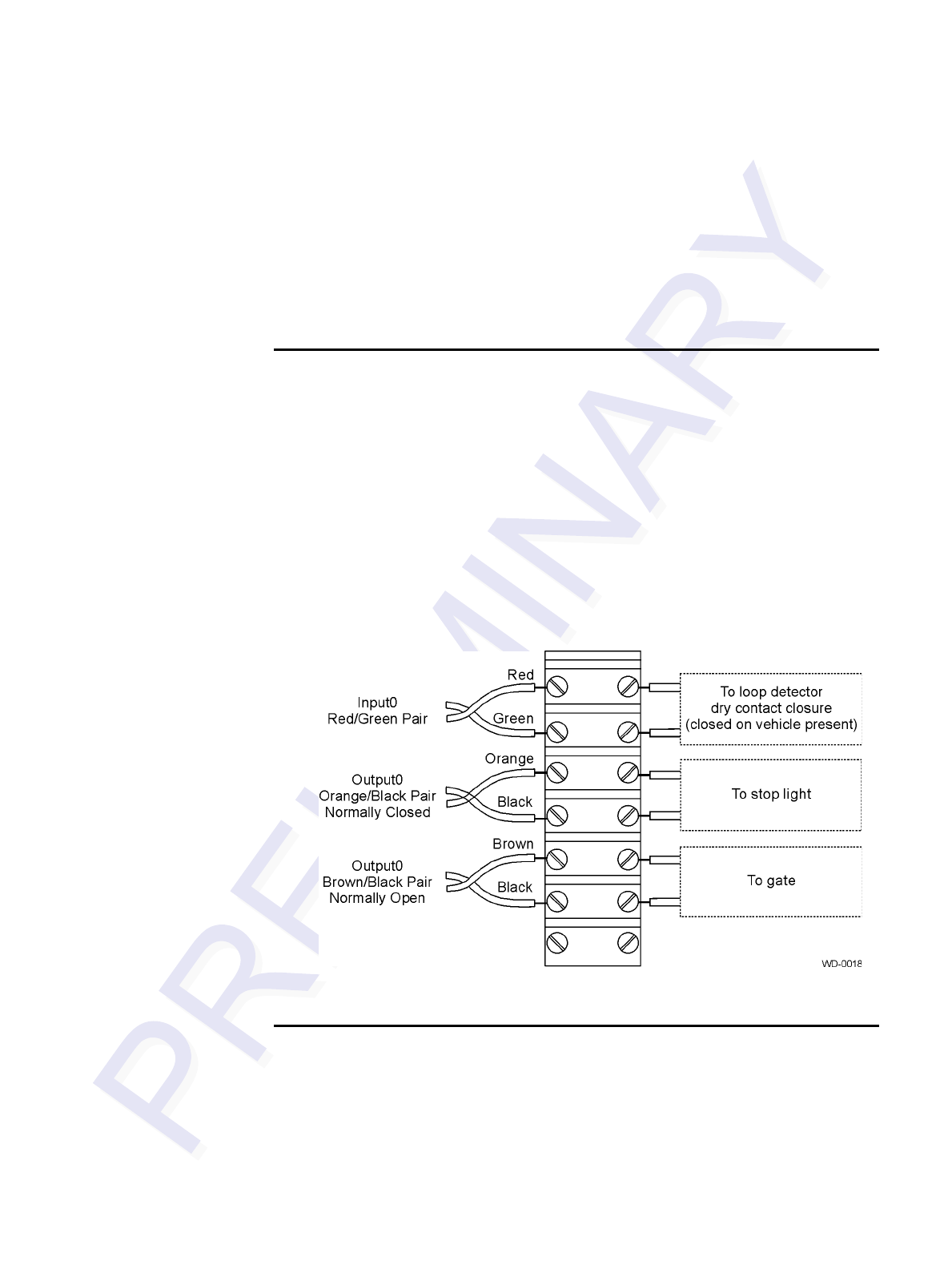
Installing the Encompass 4/4800 Multiprotocol Reader
4-29
connected to a free-of-voltage dry contact. Sense output circuits are single-pole, dou-
ble-throw relays that provide normally closed and normally open dry contacts. The
relay contacts are rated at 42.2V AC peak (30 Vrms) or 60V DC at 1 A maximum. If
controlling an external gate or device requiring high current, an isolation transformer
is required.
The following sections provide information to connect the sense input and sense out-
put circuits.
Sense Input Circuits
The Encompass 4/4800 Multiprotocol Reader supports two sense inputs – sense
input0 and sense input1– which requires two sense input lines for each loop sense or a
total of four sense input connections. Sense input0 is the presence detection device
line and is used to control RF power. As shown in Figure 4-16, sense input0 is through
the red/green wire pair on the I/O pigtail. The Encompass 4/4800 Multiprotocol
Reader expects the sense input0 circuit to close when a vehicle is present (i.e., a nor-
mally open condition). The minimum presence true period is fixed at 0 ms, which
indicates that no delay occurs in closing the circuit when a vehicle is present.
Sense input1 allows the Encompass 4/4800 Multiprotocol Reader to monitor the status
of a peripheral device. The host computer can then check the status by polling the
Encompass 4/4800 Multiprotocol Reader.
Figure 4-16 Sample Circuit Connections
Sense Output Circuits
The Encompass 4/4800 Multiprotocol Reader supports three sets of sense output sig-
nals. Two sets– sense output0 and sense output1 – provide normally open or normally
closed sense outputs. The third sense output set is dedicated for testing and set up of

Encompass 4/4800 Multiprotcol Reader System Guide
4-30
the reader. It is defined as the TAG_LOCK signal, which indicates a valid tag is in the
read field.
These sense outputs are dry contacts that provide normally open and normally closed
sense outputs. The relay contacts are rated at 42.2V AC peak (30 Vrms) or 60V DC at
1 A maximum. If controlling an external gate or device requiring high current, an iso-
lation transformer is required.
As illustrated in Figure 4-16, sense output0, normally closed, is located on the orange/
black pair. Sense output0, normally open, is located on the brown/black pair.
In Wiegand mode operation, the sense outputs are not controlled by a predefined out-
put mode.
Table 4-10 lists the cable descriptions and functions for the interface signals. These
wire pairs can be used or terminated based on the specific project applications and site
requirements.
Using Table 4-10 as a guide to the functions of each of the wire signals, connect the
remaining wires to the appropriate terminal blocks on the terminal strip in the junction
box.
Table 4-10 Sense Input/Output Cabling Assignments
Pair Pin Color Signal Description Typical Function
Blue/Red E Blue WGND0 Wiegand data0 Parking/access
control
applications
F Red WGND1 Wiegand data1 Parking/access
control
applications
White/
Red L White Lock Tag lock output,
active-closed Testing
maintenance
M Red Lock_RTN Tag lock return Testing
maintenance
Green/
Red N Green Sense Input0 Sense Input0
(loop) Loop and
presence
detection
P Red Sense
Input0_RTN Sense Input0
return; not
isolated from
signal ground
Loop and
presence
detection
Blue/
Black R Blue Sense Input1 Sense Input1 General-purpose
sense input, not
used for detecting
presence

Installing the Encompass 4/4800 Multiprotocol Reader
4-31
Caution
After connecting the wires in the communications cable, ground all drain wires
from the communications cable to the chassis ground in the NEMA enclosure.
S Black Sense
Input1_RTN Sense Input1
return; not
isolated from
signal ground
General-purpose
sense input, not
used for detecting
presence
Brown/
Black T Black Sense
Output0_COM Sense Output0
(tag detect),
common terminal
Switched output to
control gate
U Brown Sense
Output0_NO Sense Output0
normally open
terminal
Switched output to
control gate
Orange/
Black V Black Sense
Output0_COM Sense Output0
(tag detect
output), common
terminal
Switched sense
output for any
external control
(light, gate, buzzer,
etc.)
WOrangeSense
Output0_NC Sense Output0
normally closed
terminal
Switched sense
output for any
external control
(light, gate, buzzer,
etc.)
Green/
Black X Black Sense
Output1_ COM Sense Output1,
common terminal Switched sense
output
Y Green Sense
Output1_NO Sense Output1
normally open
terminal
Switched sense
output
White/
Black Z Black Sense
Output1_ COM Sense Output1,
common terminal Switched sense
output
a White Sense
Output1_NC Sense Output1
normally closed
terminal
Switched sense
output
Yellow/
Black b Yellow GND Logic ground Signal ground
used with RS–232
and Wiegand
c Black GND Logic ground Signal ground
used with RS–232
and Wiegand
Table 4-10 Sense Input/Output Cabling Assignments (continued)
Pair Pin Color Signal Description Typical Function

Encompass 4/4800 Multiprotcol Reader System Guide
4-32
Marking the Read Zone
The area where the Encompass 4/4800 Multiprotocol reads tags at the current RF
range is called the read zone. The antenna pattern, or read zone, of the Encompass 4/
4800 Multiprotocol Reader would look roughly like a pear-shaped balloon if you were
able to see it. When installing the Encompass 4/4800 Multiprotocol Reader, you
should first mark the unit’s read zone using the RF range set at the factory-default
maximum. You can later adjust the read zone using the techniques discussed in “Fine-
Tuning and Verifying the Read Zone” on page 8-20.
If two Encompass 4/4800 Multiprotocol Readers are installed near each other,
TransCore recommends that you fine-tune each reader for the ideal read zone before
connecting it permanently to sense input/sense output and communications cables. A
minimum of 2 MHz frequency separation between the two adjacent readers is required
for correct operation.
Required Materials
You need the following materials to mark the read zone:
•Test tags, supplied by the TransCore dealer or distributor
•Piece of windshield-type glass 0.190 to 0.230 inches (4.82 to 5.84 mm) in thick-
ness and approximately 12 inches (30.48 cm) square on which to attach the eGo
Windshield Sticker Tag
Caution
The eGo Windshield Sticker Tag has a reduced read range when not attached to
glass.
•Audible circuit tester and 9V DC battery for circuit tester power as described in
the section “Bench Testing the Encompass 4/4800 Multiprotocol Reader Before
Installation” on page 4-12.
•Piece of chalk or roll of tape
•Plastic or wooden yardstick for ATA tags
•Vinyl electrical tape or hook-and-loop material
Procedures
Note: Using test tags that are not mounted to vehicles give a general idea of the read
pattern but the pattern will vary somewhat when actual vehicles with tags are tested.
Final adjustments must be made with tags properly mounted on a variety of vehicles.

Installing the Encompass 4/4800 Multiprotocol Reader
4-33
To mark the read zone
1. Confirm the following:
• You have correctly connected the power supply as described “Connecting
the AC Power Supply” on page 4-6 and “Connecting the DC Power Supply”
on page 4-7.
• You have correctly connected communications as described in “Connecting
Communications” on page 4-25.
• You have correctly connected sense input and sense output circuits as
described in “Connecting Sense Input and Sense Output Circuits” on page 4-
28.
2. Connect the red and white leads from the audible tester to the red and white pair
of wires from the Encompass 4/4800 Multiprotocol Reader power/
communications cable.
3. Start the terminal emulation application Microsoft HyperTerminal by selecting
Programs>Accessories>Communications>HyperTerminal and press
ENTER.
4. In the HyperTerminal dialog boxes choose the com port to which the
communications interface is attached and set the properties as:
• Bits per second: 9600 baud
• Data bits: 8
• Parity: none
• Stop bits: 1
• Flow control: none
5. Cycle the power on the Encompass 4/4800 Multiprotocol Reader and ensure that
the sign-on message displays.
6. Input the following commands in the order provided in Table 4-6 on page 4-13.
Commands include those to switch to command mode, set operational mode, turn
on RF, and return the reader to data mode.
7. Secure the ATA test tag to the end of the yardstick using electrical tape or hook-
and-loop material or affix the test eGo Windshield Sticker Tag to the glass. Be
sure the tag polarization (horizontal or vertical alignment) matches that of the
Encompass 4/4800 Multiprotocol Reader or antenna used. If using an eGo test
tag, the glass should be in front of the tag (between the tag and the reader or
antenna).
8. Stand directly in front of and about 5 feet (1.5 m) away (see Figure 4-17) from
the Encompass 4/4800 Multiprotocol Reader or antenna. Hold the stick or the
piece of glass so that the tag is positioned at a height and angle consistent with a
tag installed on a vehicle. The test tag should cause the audible tester to sound.
Note: If you hold the test tag in your hand, your hand absorbs the RF signal and
the test results are not accurate.
9. Mark the spot with chalk or tape.
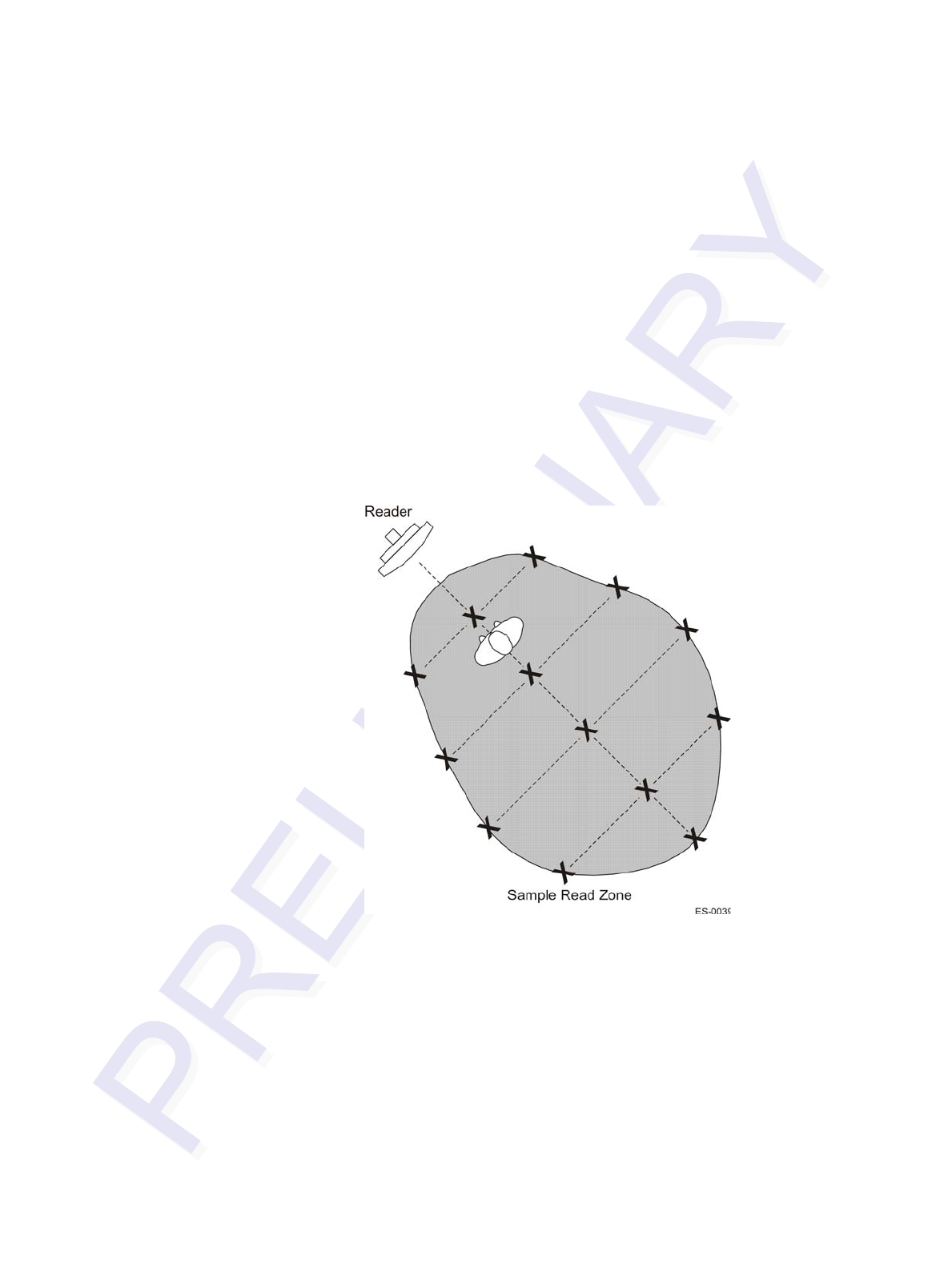
Encompass 4/4800 Multiprotcol Reader System Guide
4-34
10. Move to the left until the sound stops and mark the ground with chalk or tape at
the location of the tag when the sound stopped.
11. Return to the center and then move to the right until the sound stops and mark the
ground with chalk or tape at the location of the tag when the sound stopped.
12. Return to the center and step backward 2 feet (0.6m) and repeat steps 5 through 7.
13. Continue moving the tag in this manner, placing marks on the ground to identify
the boundary of the read zone each time the sound stops. Continue moving the
tag to various locations until the read zone is fully marked.
14. You can now connect the outer marks to draw the outer boundary of the read
zone.
Figure 4-17 is a view of a sample read zone within a controlled lane. The outer X
marks show the outside edges of the read zone.
Figure 4-17 Sample Read Zone Marking Pattern
15. Standing at the farthest point of the pattern, walk toward the Encompass 4/4800
Multiprotocol Reader or antenna and listen for a continuous sound from the
audible tester. If the sound is not continuous, it could indicate a weak or “patchy”
RF pattern. See “Fine-Tuning and Verifying the Read Zone” on page 8-20 to
adjust the read zone.

5
General Software Information


5-3
Chapter 5
General Software Information
This chapter provides software-related information for the Encompass™
4/4800 Multiprotocol Reader System.
This chapter presents various software-related topics arranged in alphabetical order by
subject. In addition to this chapter, see Chapter 6, “Communications Protocols,” and
Chapter 7, “Commands,” for more information.
Command Entry Conventions
All Encompass 4/4800 Multiprotocol Reader commands are preceded by the start-of-
message character (#). The end-of-message sequence expected from the host is a car-
riage return (CR). The Encompass 4/4800 Multiprotocol Reader terminates messages
with a return and a line-feed (CR/LF). For example, the command #01 Switch To
Command Mode is typed as follows:
#01<ENTER>
where <ENTER> is the Enter or Return key.
Some command characters may be represented by the letter N. This letter indicates
you are to supply a value. Maximum valid entries are the numbers 0 through 9 and the
uppercase letters A through F. These letters allow for as many as 16 available user
responses and are based on the hexadecimal numbering system.
Commands have at least two characters following the # character. Table 5-1 shows the
basic structure of a four-character command.
Table 5-1 Four-Character Command Structure
#1005 Set Baud Rate To 9600 Baud
# All commands are preceded by the # character.
1 Indicates the command group. This command is in Group 1-
Communications Port Control.
0 Indicates the command subgroup. In this example, all commands with
a second digit of 0 apply to the main port.
0 The command digit. In this example, the 0 indicates that this command
affects the baud rate.
5 Indicates the setting. Normally this is a variable and is usually a
hexadecimal value from 0 through F. In this example, 5 sets the baud
rate to 9600, the factory setting. In some commands, this digit may be
a four-place hexadecimal string or a character string.

Encompass 4/4800 Multiprotocol Reader System Guide
5-4
Command Response Conventions
Like the Encompass 4/4800 Multiprotocol Reader commands, responses are preceded
by the # character. Many Encompass 4/4800 Multiprotocol Reader commands respond
with #Done or #Error indicating the command was or was not recognized and
completed. Other commands respond with a four-character identifier followed by one
or more values.
Table 5-2 shows an example of a command/reply sequence. This example assumes
that an Encompass 4/4800 Multiprotocol Reader with serial number SN97001P run-
ning version X.XX software is connected to a PC running a terminal emulation soft-
ware package such as Windows Hyper Terminal or Procomm Plus. The command
sequence verifies that communications are working correctly.
In command discussions, Encompass 4/4800 Multiprotocol Reader response charac-
ters may be shown in brackets < >. The use of brackets indicates that the response is a
value in the range of characters. The brackets are not part of the response. For exam-
ple, the response to command #520 Display Power Fail Bit is either a 0 or a 1. In the
command discussion, the response is shown as:
#PWRB <0-1>
with actual Encompass 4/4800 Multiprotocol Reader response being one of the fol-
lowing:
#PWRB 0
#PWRB 1
In this example, PWRB is the four-character identifier for power fail bit, and the 0 or 1
is the value. All spaces shown in the response are actual spaces sent from the Encom-
pass 4/4800 Multiprotocol Reader. In this example, one space is between the letter B
and the number.
Table 5-2 Sample Command Sequence
Entry Encompass 4/4800 Multiprotocol
Reader Response Notes
#01 <CR> #Done <CR/LF> Switches Encompass 4/
4800 Multiprotocol Reader
to command mode.
#505
<CR> #Model eGo2000 Series Ver
X.0X SN97001P <CR/LF> Reports the software
version and serial number.
#00 <CR> #Done <CR/LF> Returns Encompass 4/4800
Multiprotocol Reader to data
mode.

General Software Information
5-5
Operating Parameters
The Encompass 4/4800 Multiprotocol Readers maintain their operating parameters in
non-volatile memory (NVRAM) so that the parameters are preserved after a power-
down sequence.
Power Fail
The system maintains a power fail flag. The host transmits command #520 Display
Power Fail Bit to determine if a power down has occurred. This flag is cleared by both
command #63 Reset Reader and command #65 Reset Power Fail Bit.
Program Download
Program download stores the Encompass 4/4800 Multiprotocol applications software
into the Encompass 4/4800 Multiprotocol Reader’s flash memory. Program download
is used to install program upgrades, add features, and to recover from corrupted pro-
gram data. The download mode supports a limited set of commands: #90 Load Pro-
gram Block, #91 Verify Flash Checksum, #96 Erase Flash Memory, #97 Perform
Destructive Memory Test, and #99 Exit Download Mode.
Download Considerations
You should consider the following factors when performing program download:
•The Encompass 4/4800 Multiprotocol Reader does not process tags while in
download mode.
•The Encompass 4/4800 Multiprotocol Reader accepts only download commands
while in download mode. It responds to all other commands with an error mes-
sage.
•The Encompass 4/4800 Multiprotocol Reader does not accept any program data
unless a successful erase of flash memory has been performed before transmitting
the data. Erasing the flash memory typically takes seven seconds.
•Exiting from download mode re-executes startup. If the new software has been
loaded without errors, the Encompass 4/4800 Multiprotocol Reader comes up in
data mode. If a flash checksum error is detected, the Encompass 4/4800 Multipro-
tocol Reader reenters download mode and transmits a sign-on message with a
boot version of 0.00x and without a serial number.
Note: The Encompass 4/4800 Multiprotocol Reader uses default communications
parameters when operating in download mode – 9600 baud, 8 data bits, 1 stop bit, no
parity, basic protocol – and does not echo commands.

Encompass 4/4800 Multiprotocol Reader System Guide
5-6
Download Procedures
If TransCore releases a new version of the Encompass 4/4800 Multiprotocol Reader
software or if the Encompass 4/4800 Multiprotocol Reader seems not to be working
properly, you may need to download the software to the Encompass 4/4800 Multipro-
tocol Reader. Contact technical support or your TransCore Encompass 4/4800 Multi-
protocol Reader sales representative.
Startup
Upon startup, Encompass 4/4800 Multiprotocol Reader’s transmit a sign-on message
or a boot ROM failure message.
Sign-On Message
If startup is successful, the sign-on message appears as follows:
Model [software version] SNYYYYYY
[Copyright notice]
where YYYYYY is the serial number assigned to the Encompass 4/4800 Multiprotocol
Reader unit being used.
Serial number 000000 is the default setting and is not a valid number. If this number
appears in the sign-on message, the serial number has never been stored into reader
memory. The serial number must be assigned by factory-authorized personnel using
command #695 Set Serial Number. Because only six digits are allowed in the
software, when setting the serial number skip the fourth (middle) digit of the seven-
digit number shown on the reader label.
If the flash memory checksum does not indicate verification, the sign-on message
appears as follows:
Model [PARC] Ver 0.00x
[Copyright notice]
Boot Failure Message
The software performs a checksum function on itself. The function returns a specific
value for the particular version of software. If the value returned is not correct, the
boot ROM checksum assumes that locations have been corrupted and a failure condi-
tion exists. If the boot ROM checksum is not correct, a boot failure message is trans-
mitted. If the failure message does not transmit, a communications error has occurred
or the boot failed to the extent that it cannot transmit the failure message.

General Software Information
5-7
If the failure message version number equals 0.00 and no serial number exists, the
flash memory checksum has failed, and the Encompass 4/4800 Multiprotocol Reader
is operating out of boot ROM. In this case, the Encompass 4/4800 Multiprotocol
Reader automatically enters download mode and waits for a new program to be loaded
into the flash memory. Follow the instructions in “Program Download” on page 5-5 to
download a new program.
Tag/Message Buffer
In basic communication protocol, the Encompass 4/4800 Multiprotocol Reader does
not provide tag memory storage beyond the quantity required for uniqueness check-
ing. This feature allows adequate buffering of tag data under normal operating condi-
tions. The Encompass 4/4800 Multiprotocol Reader cannot operate as a stand-alone
component. When the buffer fills, subsequent tag IDs will be lost.
In error correcting protocol (ECP), a buffer of up to three additional tag reads will be
held in case a host system is unable to acknowledge tag reads in real time.

Encompass 4/4800 Multiprotocol Reader System Guide
5-8

6
Communications Protocols


6-3
Chapter 6
Communications Protocols
This chapter describes the communications protocols for the
EncompassTM 4/4800 Multiprotocol Reader.
Introduction
The Encompass 4/4800 Multiprotocol Reader supports the following communica-
tions protocols:
•Basic
•Error correcting protocol (ECP)
The following protocol information provides reference information relevant to devel-
oping host software.
Communications are performed using the 7-bit ASCII code with optional parity, thus
providing easy setup, testing, and diagnostics with standard ASCII terminals and
serial printers. Parity must be enabled to achieve the specified undetected error rate.
Each message is framed within the start-of-message (som) and end-of-message (eom)
characters so that the host computer can detect the beginning and end of each mes-
sage. This convention is most important under marginal communications conditions
during which the host may receive extraneous noise-induced characters between
reader transmissions. In such instances, the host is capable of ignoring any messages
that do not conform to the som...eom frame sequence.
Both data mode and command mode require a two-way message interchange is when
using ECP. This interchange is completed by the message recipient returning a mes-
sage acknowledgement to the message sender.
With ECP, all transmissions require a message. If a message is not received, the sender
will time out with the same effect as if it had received a negative acknowledgment
(from the host) or an Error message from the Encompass 4/4800 Multiprotocol
Reader.
Software (XON/XOFF) flow control is optionally supported. Be careful in the use of
XON/XOFF since noise-induced characters may be interpreted by the Encompass 4/
4800 Multiprotocol Reader as the XOFF character, which would suspend reader out-
put without information reaching the host computer. For more information see “Soft-
ware Flow Control” on page 8-19.
Note: TransCore recommends that XON/XOFF flow control be disabled while using
ECP.

Encompass 4/4800 Multiprotocol Reader System Guide
6-4
Basic Protocol
With basic protocol, messages sent to and from the Encompass 4/4800 Multiprotocol
Reader and the host are transmitted without error checking. For each host transmis-
sion, the Encompass 4/4800 Multiprotocol Reader returns a Done or Error message
to the host.
When the host computer is physically close to the Encompass 4/4800 Multiprotocol
Reader and no sources of interference exist, the basic protocol provides reliable com-
munications.
The host must be ready to receive reader-transmitted messages because in basic proto-
col the Encompass 4/4800 Multiprotocol Reader does not wait for the host to
acknowledge a message before transmitting the next message. If necessary, the host
may halt reader transmissions by using software or hardware flow control. Refer to
Chapter 8 for flow control information.
Error Correcting Protocol
When the quality of data communications is imperative or may be suspect, you can
invoke ECP to ensure the integrity of data transmitted between the Encompass 4/4800
Multiprotocol Reader and the host.
Note: TransCore recommends that basic protocol (not ECP) be used when commands
are entered manually at the keyboard.
Wiegand output is automatically disabled when the reader is put into ECP mode.
Error correction is accomplished with the use of a cyclic redundancy check (CRC)
value that is based on the message data. The originator (reader or host) calculates the
CRC value of a message and includes it in the transmitted message.
The recipient (reader or host) also calculates a CRC value for the received message. If
the transmitted message data is correct, the CRC value calculated by the recipient will
agree with the CRC value calculated by the originator. If the CRC values do not agree,
the recipient rejects the message.
Message sequence numbers are also included when using ECP. These sequence num-
bers are checked to determine if the message received has the correct sequence num-
ber; if not, the recipient rejects the message.
Since the seven-bit ASCII code is used and there are eight data bits per character, the
eighth bit can optionally be used to support parity. Where parity is selected, the CRC
value calculation includes the parity of each character in the calculation of the CRC
value.
Parity is required to achieve the most reliable communications. If parity is enabled,
both the Encompass 4/4800 Multiprotocol Reader and the host must issue a message
if any received character has a parity error. However, the message must not be trans-

Communications Protocols
6-5
mitted before receipt of the eom character. In this case, the Encompass 4/4800 Multi-
protocol Reader will issue an Error message, and the host computer will issue a
negative acknowledgment message.
Basic Protocol and ECP Format
Note: In the following text, the symbols < and > are used to represent required vari-
able message data, and the symbols [and] are used to represent optional data. These
symbols are not part of the message syntax.
Reader Transmissions
The basic protocol format and the data inquiry protocol format are as follows:
<som><data><eom>
The ECP format is as follows:
<som><seq><data><crc><eom>
where
<som> Start-of-message (ASCII # character)
<seq> Sequence number (ASCII hex) that represents an even number in
the range 0–9, A–F (0, 2, 4, 6, 8, A, C, E). The Encompass 4/4800
Multiprotocol Reader maintains the number. The host must
acknowledge reader transmissions by sending an ACK message
with the same sequence number received from the Encompass 4/
4800 Multiprotocol Reader. The Encompass 4/4800
Multiprotocol Reader updates its sequence number upon receipt
of a valid host ACK. If an ACK is not received, the Encompass 4/
4800 Multiprotocol Reader retransmits the message. A reader
transmission sequence is not considered complete until the
Encompass 4/4800 Multiprotocol Reader receives an ACK and
updates its sequence number.
<data> An ASCII string up to 72 characters long. This string may contain
tag data, a presence without tag report; an input status change
report; an Error06, Error07, Error08, or Error11
message; or a sign-on message. Auxiliary data may also be
included.
<crc> Field containing four ASCII digits that represent the 16-bit CRC
value calculated on the message. The CRC value is calculated on
bytes between the som character and the first <crc> byte.
When the host receives a properly framed message, it can
calculate a 16-bit CRC value. The calculation is applied to the

Encompass 4/4800 Multiprotocol Reader System Guide
6-6
character string that immediately follows the <som> and that
ends with the character immediately preceding the first <crc>
character.
The transmitted CRC value can then be compared with the binary
equivalent of the received <crc> characters. If the transmitted
and received CRC values do not match, the recipient assumes the
message was received in error, and transmits a NAK message
response.
<eom> End-of-message characters (ASCII CR and LF). The system
includes both a carriage return (CR) and line feed (LF) to
facilitate the use of terminals and printers.
If the host receives a <som> character in the middle of a data
message, the message in progress is aborted. The assumption is
that an <eom> was lost and the Encompass 4/4800
Multiprotocol Reader is in the process of retransmitting the
previous message.
ECP Host ACK/NAK Response
With ECP, the host computer responds to all data message transmissions from the
Encompass 4/4800 Multiprotocol Reader using the following acknowledgment or
negative acknowledgment response format.
<som><seq><ack/nak><crc><eom>
where
<som> Start-of-message (ASCII # character)
<seq> An echo of the sequence number received from the Encompass 4/
4800 Multiprotocol Reader. The sequence number should
correspond to the data message that is being positively or
negatively acknowledged by the host. If the Encompass 4/4800
Multiprotocol Reader receives an ACK message with the
incorrect sequence number, the data message is retransmitted.
The host computer resets the anticipated data message sequence
number to that of the Encompass 4/4800 Multiprotocol Reader
before communications can resume without error.
<ack/nak> ASCII @ character for ACK response; ASCII ? character for NAK
response
<crc> CRC value for the message
<eom> End-of-message character (ASCII CR)

Communications Protocols
6-7
The Encompass 4/4800 Multiprotocol Reader sets a user-programmable timeout
delay at the time each message is transmitted based on command #612NN Select
Error Correcting Protocol Timeout, where NN = timeout delay. To dis-
able the timeout delay for diagnostic purposes, issue the command #612FF Disable
Error Correcting Protocol Timeout.
If the timeout delay expires before the Encompass 4/4800 Multiprotocol Reader
receives an ACK or NAK message from the host, a logical NAK condition will be
declared. If the Encompass 4/4800 Multiprotocol Reader receives a NAK or timeout,
the reader retransmits the data message.
When the Encompass 4/4800 Multiprotocol Reader receives an ACK message, the
system software treats the message as having been properly received by the host. The
software increments the sequence number, and advances pointers to the next message
in the Encompass 4/4800 Multiprotocol Reader’s message queue to prepare for send-
ing the next message.
Switch to Command Mode Request
The host computer may issue command #01 Switch to Command Mode while in
data mode.
The basic protocol format is as follows:
<som><cmd><eom>
The ECP format is as follows:
<som><seq><cmd><crc><eom>
where
<som> Start-of-message (ASCII # character)
<seq> Sequence number generated by the host computer separately
from that appearing in data messages transmitted by the
Encompass 4/4800 Multiprotocol Reader
<cmd> Switch to command mode (ASCII characters 01)
<crc> CRC value for the message
<eom> End-of-message character (ASCII CR)
Host Transmission
The host computer initiates synchronous communications between the Encompass 4/
4800 Multiprotocol Reader and the host. The host begins a sequence by issuing a
command; the Encompass 4/4800 Multiprotocol Reader responds accordingly.

Encompass 4/4800 Multiprotocol Reader System Guide
6-8
The basic protocol format is as follows:
<som><cmd>[<data>]<eom>
The ECP format is as follows:
<som><seq><cmd>[<data>]<crc><eom>
where
<som> Start-of-message (ASCII # character)
<seq> Sequence number (ASCII hex digit) that represents an odd
number in the range 0–9, A–F (1, 3, 5, 7, 9, B, D, F). The host
should use odd sequence numbers in its command since the
Encompass 4/4800 Multiprotocol Reader uses even sequence
numbers in its transmissions. This method eliminates the
possibility of a synchronous host command and an asynchronous
reader transmission having the same sequence number.
Upon receiving a host command, the Encompass 4/4800
Multiprotocol Reader echoes the command’s sequence number
in its response. Therefore, the host computer updates its sequence
number upon receipt of a valid reader message. If the sequence
number is not updated before transmission of the next command,
the Encompass 4/4800 Multiprotocol Reader will not service the
new command; it will retransmit its previous message. A
command/message sequence is not complete until the host
updates its sequence number.
<cmd> Command code, a string that contains from two to four ASCII
hex characters
[<data>] Optional data field, an ASCII string of as many as 20 characters
in length. For example, the store hardware configuration string
command is #696S...S or command #696 Store Hardware
Configuration String followed by the data string S...S.
<crc> CRC value for the message
<eom> End-of-message character (ASCII CR)
Reader Command Response
The basic protocol format is
<som><resp><eom>
The ECP format is
<som><seq><resp><crc><eom>

Communications Protocols
6-9
where
<som> Start-of-message (ASCII # character)
<seq> Echo of sequence number received in host command message
<resp> Response string. The Encompass 4/4800 Multiprotocol Reader
returns Done, Error, or another ASCII string depending on the
host transmission. This string can be up to 72 characters long.
<crc> CRC value for the message
<eom> End-of-message character (ASCII CR and LF)
Sample Messages
This section contains examples of typical messages transmitted between the Encom-
pass 4/4800 Multiprotocol Reader and the host computer.
Reader Transmissions
Basic protocol reader transmission
#KING 1302<eom>
Host response
No host response for non-ECP
ECP reader transmission
#4KING 1302 <crc><eom>
where
#Start-of-message character
4Message sequence number
KING 1302 Message data: Tag ID is shown.
Other sample message data could be as follows:
IOST C0 O2 I0 D24 (display I/O status)
Error06 (frequency not set)
<crc> CRC value for the message
<eom> End-of-message character
Host response
#4@<crc><eom>

Encompass 4/4800 Multiprotocol Reader System Guide
6-10
where
#Start-of-message character
4Message sequence number
@ ACK (acknowledgment character)
(? returned for a negative acknowledgment)
<crc> CRC value for the message
<eom> End-of-message character
Host Command Transmissions
Basic protocol host transmission
#64202<eom>
Reader response
#Done<eom> or #Error<eom>
#Error<eom> is returned if the host transmission is not a legal command with legal
data.
ECP host transmission
#764202<crc><eom>
where
#Start-of-message character
7Message sequence number
64202 Select RF Operating Frequency command where
642NN is the command and NN is a hexadecimal value from 00
to 34. In this example, 02 sets the RF frequency to 903 MHz.
<crc> CRC value for the message
<eom> End-of-message character
Done Command has been invoked by the Encompass 4/4800
Multiprotocol Reader
Reader response
#7Done<crc><eom> or #7Error<eom>
For some commands, the Encompass 4/4800 Multiprotocol Reader responds with
data that relates to the command, such as T0F 0, to indicate Wiegand mode enabled
for a 532 Display Wiegand Mode Status command.

Communications Protocols
6-11
#7Error<eom> will be returned if host transmission is not a legal command with
legal data.
Timing and Synchronization
The ECP is largely independent of baud rate. The timeout delays previously described
are a function of baud rate.
The Encompass 4/4800 Multiprotocol Reader supports an ECP timeout, which
applies equally to both transmit and receive.
The receiver’s minimum timeout delay equals the time to transmit/receive the longest
anticipated message at the current baud rate setting. Additional margin should be
included for idle periods between characters; for example, processing overhead, if
any. The timeout delay period can be expressed as follows:
Τrec (ms) = L x [Τchar + Τidle]
where
Τchar (ms) 1000 x [ Bc / Rb ]
BcBits per character, typically 10
RbBaud rate, 2400–38.4 K
LLength of message in characters
Τidle Maximum idle period between characters (ms)
Note: The Encompass 4/4800 Multiprotocol Reader supports baud rates between
2400 and 38.4 K.
Likewise, the sender must set a timeout delay equal to the delay of nine characters at
the current baud rate setting. For example, the time required to shift out the <eom>
character plus the time to shift in the ACK or NAK message to be received plus a pro-
cessing allowance for the receiver to process the message and check for error condi-
tions.
Thus, the sending timeout delay can be expressed as follows:
Τsend (ms) = 9 * Τchar + Τerrchk
where
Τerrckh (ms) Processing period to perform error checking by receiver
The host computer can remotely set the Encompass 4/4800 Multiprotocol Reader’s
communications parameters while in the command mode, but TransCore does not rec-
ommend this action if communications conditions are marginal.

Encompass 4/4800 Multiprotocol Reader System Guide
6-12
After the Encompass 4/4800 Multiprotocol Reader receives new communications
parameters, the Encompass 4/4800 Multiprotocol Reader issues the Done message
and switches to the new configuration immediately. The host computer switches its
communications parameters immediately after the transaction is complete.
As noted, the message initiator, such as the Encompass 4/4800 Multiprotocol Reader
in data mode and the host computer in command mode, starts a timeout counter at the
time a message is transmitted. If the timeout expires before receiving an acknowledge-
ment message, a logical NAK condition is declared, and the initiator assumes the mes-
sage was received in error. In this instance, the message is retransmitted until an
acknowledgement message is received.
The message recipient, such as the host computer in data mode and the Encompass 4/
4800 Multiprotocol Reader in command mode, starts a timeout counter when a
<som> character is received. If the timeout expires without the receipt of an <eom>,
the message acquisition is aborted (reset), and the receiver waits for the next <som>
character.
If the message recipient receives a second <som> character before an <eom> charac-
ter, the message acquisition is aborted (reset), and retransmission of the previous mes-
sage is assumed to be underway.
These strategies allow for recovery during periods when communications are marginal
or completely lost.
Note: It is important that the host computer limit the period during which the Encom-
pass 4/4800 Multiprotocol Reader remains in command mode to avoid losing tag IDs.
RF is off in command mode and no tags can be read.
Reader-Addressed Failure Conditions
The Encompass 4/4800 Multiprotocol Reader addresses the following failure condi-
tions.
Illegal Sequence Number (not in the range 0–9, A–F)
If the Encompass 4/4800 Multiprotocol Reader detects an illegal sequence number in
a host command message, it discards the received message and sends no response. If it
receives an illegal sequence number in an ACK message, it responds as if a NAK had
been received and retransmits the data.
Wrong Sequence Number
If the Encompass 4/4800 Multiprotocol Reader receives the wrong sequence number
in an ACK message, it responds as if a NAK had been received, and it retransmits the
data.
Incorrect CRC
If the Encompass 4/4800 Multiprotocol Reader detects an incorrect CRC value in a
host command message, it discards the received message. No response is sent. If it
receives an incorrect CRC value in an ACK message, it responds as if a NAK had been
received, and it retransmits the data.

Communications Protocols
6-13
Illegal Command
If the Encompass 4/4800 Multiprotocol Reader receives an illegal command, it
returns its standard Error message.
Transmission Timeout
If the Encompass 4/4800 Multiprotocol Reader transmits an asynchronous message
and the host does not send an ACK before the ECP timeout occurs, the Encompass 4/
4800 Multiprotocol Reader retransmits the message.
Receive Timeout
If the Encompass 4/4800 Multiprotocol Reader receives a <som> but does not receive
a matching <eom> before the ECP timeout occurs, it discards the incomplete message
and resets its receiver.
Asynchronous Message/Command Message Collision
If the Encompass 4/4800 Multiprotocol Reader transmits asynchronous data at the
same time that the host sends a command, the Encompass 4/4800 Multiprotocol
Reader gives priority to receiving the command. It processes the command and sends
a message before it retransmits the asynchronous data.
Host-Addressed Failure Conditions
The host computer addresses the following failure conditions.
Illegal or Wrong Sequence Number
If the host detects an illegal or wrong sequence number in a reader response, it retrans-
mits the command with the same sequence number. If the host detects an illegal
sequence number in an asynchronous reader transmission, it sends a NAK message.
Incorrect CRC
If the host detects an incorrect CRC value in a reader message, it retransmits the com-
mand with the same sequence number. If the host detects an incorrect CRC value in an
asynchronous reader transmission, it transmits a NAK message.
Transmission Timeout
If the Encompass 4/4800 Multiprotocol Reader does not respond to a host command
within a specified interval, the host software retransmits the command with the same
sequence number.
Receive Timeout
If the host receives a <som> but does not receive a matching <eom> within a specified
timeout interval, it discards the incomplete message and resets its receiver.

Encompass 4/4800 Multiprotocol Reader System Guide
6-14
Asynchronous Message/Command Message Collision
If the host receives an asynchronous reader transmission at the same time it transmits
a command, it ignores the asynchronous message and waits for the Encompass 4/4800
Multiprotocol Reader’s response. The Encompass 4/4800 Multiprotocol Reader
retransmits asynchronous data after it transmits the command message.
ECP Reliability
An undetected error is defined as a message having incorrect data or status but no par-
ity or CRC errors. An error transaction is defined as a message having either a parity
or CRC error. Laboratory testing indicates an undetected error rate of less than one
undetected error per 1,000,000 error transactions with parity enabled.
To ensure this error rate is not exceeded, the host must enable parity and adhere
closely to the timing specifications discussed previously in this chapter in the “Timing
and Synchronization” section.
CRC Calculation
The CRC used by the ECP is based on a 16-bit algorithm. The algorithm, as imple-
mented, operates on eight-bit characters, for example, seven-bit ASCII character plus
one optional parity bit. The 16-bit result is converted to four ASCII hex characters and
is appended to messages transmitted by the Encompass 4/4800 Multiprotocol Reader.
The Encompass 4/4800 Multiprotocol Reader accepts four ASCII < ` > characters (60
hex) as a wild card CRC value in lieu of a valid four-character CRC value to facilitate
testing and diagnostic checkout.
The Encompass 4/4800 Multiprotocol Reader implements the algorithm with a 512-
byte lookup table to reduce the processing overhead requirements.
To simplify the implementation of the CRC algorithm by host software developers,
several examples of the calculation are provided in C source code on the following
pages. The calculation may be performed with or without a lookup table, depending
on the trade-off between code memory and processing overhead.
Example 1 presents an example of a function (CALCCRC) that calculates the CRC
value through a call to a separate function (UPDCRC).
unsigned short calccrc(char *message)
{
unsigned short crc = 0;
for ( ; *message != (char)0;message++)
crc = updcrc(*message & 0xff, crc);
return (crc)
}

Communications Protocols
6-15
Example 3 contains an example of UPDCRC that does require a lookup table.
Example 2 shows an example of UPDCRC that does not require a lookup table.
#define BITS_PER_CHAR 8
unsigned short updcrc (unsigned short ch, unsigned short
crc)
{
register short counter = BITS_PER_CHAR;
register short temp = crc;
while (--counter >= 0)
if (temp & 0x8000) {
temp <<= 1;
temp += (((ch <<= 1) & 0x0100) != 0);
temp ^= 0x1021;
}
else {
temp <<= 1;
temp += (((ch <<= 1) & 0x0100) != 0);
}
return(temp);
}
#define updcrc(cp, crc)( crctab[((crc >> 8) & 255)]^ (crc << 8) ^ cp
static unsigned short crctab [256] = {
0x0000, 0x1021, 0x2042, 0x3063, 0x4048, 0x50a5, 0x60c6, 0x70e7,
0x8108, 0x9129, 0xa14a, 0xb16b, 0xc18c, 0xd1ad, 0xe1ce, 0xf1ef,
0x1231, 0x0210, 0x3273, 0x2252, 0x52b5, 0x4294, 0x72f7, 0x62d6,
0x9339, 0x8318, 0xb37b, 0xa35a, 0xd3bd, 0xc39c, 0xf3ff, 0xe3de,
0x2462, 0x3443, 0x0420, 0x1401, 0x64e6, 0x74c7, 0x44a4, 0x5485,
0xa56a, 0xb54b, 0x8528, 0x9509, 0xe5ee, 0xf5cf, 0xc5ac, 0xd58d,
0x3653, 0x2672, 0x1611, 0x0630, 0x76d7, 0x66f6, 0x5695, 0x46b4,
0xb75b, 0xa77a, 0x9719, 0x8738, 0xf7df, 0xe7fe, 0xd79d, 0xc7bc,
0x48c4, 0x58e5, 0x6886, 0x78a7, 0x0840, 0x1861, 0x2802, 0x3823,
0xc9cc, 0xd9ed, 0xe98e, 0xf9af, 0x8948, 0x9969, 0xa90a, 0xb92b,
0x5af5, 0x4ad4, 0x7ab7, 0x6a96, 0x1a71, 0x0a50, 0x3a33, 0x2a12,
0xdbfd, 0xcbdc, 0xfbbf, 0xeb9e, 0x9b79, 0x8b58, 0xbb3b, 0xab1a,
0x6ca6, 0x7c87, 0x4ce4, 0x5cc5, 0x2c22, 0x3c03, 0x0c60, 0x1c41,
0xedae, 0xfd8f, 0xcdec, 0xddcd, 0xad2a, 0xbd0b, 0x8d68, 0x9d49,
0x7e97, 0x6eb6, 0x5ed5, 0x4ef4, 0x3e13, 0x2e32, 0x1e51, 0x0e70,
0xff9f, 0xefbe, 0xdfdd, 0xcffc, 0xbf1b, 0xaf3a, 0x9f59, 0x8f78,

Encompass 4/4800 Multiprotocol Reader System Guide
6-16
Example 4 shows an example of a function that creates the lookup table.
#include <stdio.h>
#define MAX_CHAR 256
#define BITS_CHAR 8
#define SIGN_BIT 0x8000
#define POLY 0x1021
unsigned short crctab [MAX_CHAR];
main ()
{
unsigned short ch;
unsigned short workval;
unsigned short bit;
unsigned short carry;
for (ch = 0; ch != MAX_CHAR; ch++) {
workval = ch << BITS_CHAR;
for (bit = BITS_CHAR; bit != 0; bit--) {
carry = (workval & SIGN_BIT);
workval <<= 1;
if (carry)
workval ^= POLY;
}
crctab[ch] = workval;
0x9188, 0x81a9, 0xb1ca, 0xa1eb, 0xd10c, 0xc12d, 0xf14e, 0xe16f,
0x1080, 0x00a1, 0x30c2, 0x20e3, 0x5004, 0x4025, 0x7046, 0x6067,
0x83b9, 0x9398, 0xa3fb, 0xb3da, 0xc33d, 0xd31c, 0xe37f, 0xf35e,
0x02b1, 0x1290, 0x22f3, 0x32d2, 0x4235, 0x5214, 0x6277, 0x7256,
0xb5ea, 0xa5cb, 0x95a8, 0x8589, 0xf56e, 0xe54f, 0xd52c, 0xc50d,
0x34e2, 0x24c3, 0x14a0, 0x0481, 0x7466, 0x6447, 0x5424, 0x4405,
0xa7db, 0xb7fa, 0x8799, 0x97b8, 0xe75f, 0xf77e, 0xc71d, 0xd73c,
0x26d3, 0x36f2, 0x0691, 0x16b0, 0x6657, 0x7676, 0x4615, 0x5634,
0xd94c, 0xc96d, 0xf90e, 0xe92f, 0x99c8, 0x89e9, 0xb98a, 0xa9ab,
0x5844, 0x4865, 0x7806, 0x6827, 0x18c0, 0x08e1, 0x3882, 0x28a3,
0xcb7d, 0xdb5c, 0xeb3f, 0xfb1e, 0x8bf9, 0x9bd8, 0xabbb, 0xbb9a,
0x4a75, 0x5a54, 0x6a37, 0x7a16, 0x0af1, 0x1ad0, 0x2ab3, 0x3a92,
0xfd2e, 0xed0f, 0xdd6c, 0xcd4d, 0xbdaa, 0xad8b, 0x9de8, 0x8dc9,
0x7c26, 0x6c07, 0x5c64, 0x4c45, 0x3ca2, 0x2c83, 0x1ce0, 0x0cc1,
0xef1f, 0xff3e, 0xcf5d, 0xdf7c, 0xaf9b, 0xbfba, 0x8fd9, 0x9ff8,
0x6e17, 0x7e36, 0x4e55, 0x5e74, 0x2e93, 0x3eb2, 0x0ed1, 0x1ef0,
};

Communications Protocols
6-17
}
for (ch = 0; ch != MAX_CHAR; ch++)
printf("0x%04x\n", crctab[ch]);
}
Manually Disabling ECP for Maintenance
Under certain conditions, communications between the host and Encompass 4/4800
Multiprotocol Reader may be lost temporarily and maintenance may be required. The
reader or host is sending out a message and waiting for an acknowledgment. When the
acknowledgment is not received, the message is sent again. Additional messages are
also buffered. Often the first indication that the Encompass 4/4800 Multiprotocol
Reader software is in an ECP “loop” is when the user/technician sees a recurring dis-
play of the same message repeated over and over again on the monitor. The procedure
described in the following paragraphs enables the maintenance technician to change
configuration or test tag reading manually.
Assuming that the ECP timeout is at the factory default of 12.7 seconds (or other value
that allows enough time for the commands to be manually entered) the following com-
mand sequence may be used to break out of an ECP loop. This command sequence
uses four ASCII < ` > characters (60 hex) as wild card CRC values.
Note: The ASCII <`> character (60 hex) is commonly located on the ~ key.
You must acknowledge existing messages by issuing commands with the generic for-
mat:
#x@‘‘‘‘<eom>
where
#Start-of-message character
xMessage sequence number. This must be the same as the
sequence number of the message being acknowledged
@ACK (acknowledgment character)
<‘‘‘‘> Wild card CRC value for the message
<eom> End-of-message character
The following is a typical sequence after power-on limiting buffered messages.
Note: Ensure that no tags are in the field when you are performing this troubleshoot-
ing procedure.
Caution
To avoid damage to the Encompass 4/4800 Multiprotocol Reader that uses an exter-
nal antenna, ensure that you have connected the antenna or a dummy load to the
reader before applying power to the reader.

Encompass 4/4800 Multiprotocol Reader System Guide
6-18
Reader transmission on power-up:
#0 Model …. SN <crc><eom>
Manually enter: #0@````<eom>
Reader transmission #2 Copyright 2003 TransCore <crc><eom>
Manually enter: #2@````<eom>
Manually enter: #101‘‘‘‘<eom> this puts reader into command mode
Reader response: #1Done<crc><eom>
Manually enter: #3610‘‘‘‘<eom> this puts reader into basic protocol,
disabling ECP
reader response: Done
Enter any other desired diagnostic or directive commands in basic protocol. After
maintenance is complete enter the command:
#00 to return the reader to data mode
or
#611 to return to error correcting protocol,
and then either cycle power or issue
#100````<eom> command to return
reader to data mode

7
Commands


7-3
Chapter 7
Commands
This chapter discusses the host-transmitted commands that are used to
control the EncompassTM 4/4800 Multiprotocol Reader configuration and
operation.
Introduction
The Encompass 4/4800 Multiprotocol Reader is delivered from the factory with spec-
ified default settings that determine how the reader operates. Commands transmitted
by the host computer can change the default settings and control additional features.
The commands can be transmitted by manually entering the commands at the host
keyboard if the host is in terminal emulation mode. The Encompass 4/4800 Multipro-
tocol Reader can also communicate with ASCII terminals.
Note: If you are using Wiegand mode, you must connect the PC or laptop to the
Encompass 4/4800 Multiprotocol Reader using the RS–232 or RS–422 interface and a
terminal emulation program to send commands to the reader. You can leave the Wie-
gand interface connected during this procedure.
Operating Modes
The Encompass 4/4800 Multiprotocol Reader has three modes of operation: data
mode, command mode, and download mode. The software for the Encompass 4/4800
Multiprotocol Reader contains two separate programs — boot and application. The
boot program has control of the Encompass 4/4800 Multiprotocol Reader on startup
and when operating in download mode. The application program has control of the
Encompass 4/4800 Multiprotocol Reader during data mode and command mode oper-
ation and holds the application code. Together, they control the Encompass 4/4800
Multiprotocol Reader in the three modes of operation.
Data Mode
The Encompass 4/4800 Multiprotocol Reader is in the data mode upon power-up.
While in the data mode, the Encompass 4/4800 Multiprotocol Reader sends all com-
munications as data messages, such as tag IDs and reports, to the host computer.
Reports provide information on input status changes (input0 and input1), a presence
without tag report, and buffer overflow information. The host computer can send only
two commands to the Encompass 4/4800 Multiprotocol Reader while in data mode:

Encompass 4/4800 Multiprotocol Reader System Guide
7-4
•Command #01 Switch To Command Mode changes the Encompass 4/4800 Mul-
tiprotocol Reader from the data mode to the command mode. See “01 Switch to
Command Mode” on page 7-6.
•Command #05 Switch To Download Mode allows the host computer to download
new software into the Encompass 4/4800 Multiprotocol Reader. See “05 Switch to
Download Mode” on page 7-6.
Note: The Encompass 4/4800 Multiprotocol Reader transmits ID codes to the host
computer when the Encompass 4/4800 Multiprotocol Reader is in data mode. If the
Encompass 4/4800 Multiprotocol Reader remains in the command mode with tags
passing through the read zone, all tag IDs are lost.
Command Mode
While the Encompass 4/4800 Multiprotocol Reader is in the command mode, the host
computer sends commands to the Encompass 4/4800 Multiprotocol Reader that can be
used to control the operation and configuration of the reader. After the Encompass 4/
4800 Multiprotocol Reader receives a command, it transmits a command response
message. Typically, the command message contains Error, Done, or data relating
specifically to the command request. These messages may be of variable length since
some commands require information as part of the message; for example, Display
Wiegand Mode Status.
Communications can be lost if the host computer attempts to send certain commands
under marginal communications conditions. For example, if the host computer trans-
mits the command request to change the baud rate and the Encompass 4/4800 Multi-
protocol Reader properly receives the request and transmits the Done message, one of
the two following conditions may occur:
•If the host computer receives the Done message, then both the host and the
Encompass 4/4800 Multiprotocol Reader switch to the new baud rate, and com-
munications are maintained.
Note: In many applications, the host must be set to the new baud rate as it will not
change automatically.
Note: The Encompass 4/4800 Multiprotocol Reader changes the baud rate immedi-
ately after issuing the Done message.
•However, if the host does not receive the Done message transmitted by the
Encompass 4/4800 Multiprotocol Reader, the host assumes that the command was
not properly sent and does not switch to the new baud rate, causing a loss of com-
munications.
Caution
The host computer should not attempt to change communications parameters or
protocols during marginal communications conditions; otherwise, a loss of commu-
nications can result.

Commands
7-5
Download Mode
In download mode, the Encompass 4/4800 Multiprotocol Reader allows the host to
download new software and supports a limited set of commands.
While in download mode, the reader communications port parameters are fixed at the
following factory-default settings: 9600 baud, 8 data bits, 1 stop bit, no parity, soft-
ware flow control (XON/XOFF), basic protocol.
While in download mode, the Encompass 4/4800 Multiprotocol Reader turns RF off,
does not process tags, and does not echo host commands. See “90 Load Program
Block” on page 7-46 through “99 Exit Download Mode” on page 7-47.
Command List
Reader commands are divided into groups based on primary function. The following
sections provide information about each command in command number order. Refer
to Appendix D for listings of commands in numerical and alphabetical order.
Some commands supported by TransCore’s AI1620 SmartPass readers are not
available or have been changed for the Encompass 4/4800 Multiprotocol Reader.
Other commands, such as command #644NN Set RF Attenuation and #6402
Enable Diagnostic RF Continuous Wave, have been added for the Encompass 4/4800
Multiprotocol Reader. Further, commands have been added that are supported only in
later versions of the Encompass 4/4800 Multiprotocol Reader Software. These com-
mands are indicated as follows:
•A single asterisk (*) indicates that the command has been altered so that it is dif-
ferent from the AI1620 SmartPass command.
•A double asterisk (**) indicates a new command or added value that is not present
in the AI1620 SmartPass command list.
•A triple asterisk (***) indicates an Encompass 4/4800 Multiprotocol Reader com-
mand that is supported only in later versions of the Encompass 4/4800 Multiproto-
col Reader Software. Commands so indicated have explanatory notes.
The Encompass 4/4800 Multiprotocol Reader System does not include a real-time
clock. The dual-protocol Encompass 4/4800 Multiprotocol Reader internal timing var-
ies depending on the operative tag read mode and the type of tag in the read field.
Unless stated otherwise, values listed for timing-related command variables assume
an ID operational mode (64-bit ID data from eGo tags, ignoring ATA tags) and an
eGo-compatible tag in the read field and these values may vary.
In the following text, the symbols < and > represent variable message data. These
symbols are not part of the message syntax.
Hex digits (0–9, A–F) in either uppercase or lowercase characters may be used in data
strings and for hex digits A–F.

Encompass 4/4800 Multiprotocol Reader System Guide
7-6
Reader Mode Control — Command Group 0
Group 0 commands control reader mode. The mode determines whether the reader is
transmitting data to or receiving data from a host computer or terminal.
00 Switch to Data Mode (Factory Default)
Command #00 switches the reader to data mode, which allows the reader to transmit
tag data (ID codes) to the host. The reader enters data mode on power up.
While operating in data mode, the reader accepts the following commands:
•Command #01 Switch to Command Mode
•Command #05 Switch to Download Mode
Reader response:
Done
01 Switch to Command Mode
Command #01 switches the reader to command mode, which allows the reader to
accept commands from a host or terminal. While in command mode, the reader turns
RF off and does not acquire tags.
Reader response:
Done
05 Switch to Download Mode
Command #05 switches the reader to download mode, which allows an external host
computer to download new software into the reader flash memory.
While operating in download mode, the reader accepts a limited set of commands:
#90 Load Program Block, #91 Verify Flash Checksum, #96 Erase Flash Memory,
#97 Perform Destructive Memory Test, and #99 Exit Download Mode.
To exit the download mode, the host must transmit command #99 Exit Download
Mode. The reader re-executes startup to ensure proper initialization of operating
parameters and to verify the boot ROM and flash memory checksum values. The
reader does not accept the command #05 Switch To Download Mode if it is operating
in data mode; it must first be switched to command mode (command #01).
Reader response:
Done or Error
Commands
7-7
Communications Port Control — Command
Group 1
Group 1 commands configure the parameters used by the Encompass 4/4800 Multi-
protocol Reader to communicate with a host computer or terminal. These commands
set baud rate, stop bits, parity, and end-of-line delay.
100N Select Baud Rate*
Command #100N selects the reader baud rate. The factory-default setting is 9600
baud. The N variable specifies the baud rate shown in Table 7-1.
Caution
If ECP is enabled, ensure that the ECP timeout is sufficient for the new baud rate.
See “Timing and Synchronization” on page 6-11.
Reader response:
Done or Error
101N Select Stop Bits
Command #101N selects the number of stop bits for reader character transmission.
The factory default setting is 1 stop bit. The N variable specifies the number of stop
bits as indicated in Table 7-2.
Table 7-1 Select Baud Rate Commands
Command Baud Rate Selected
1002*** (supported only in Encompass 4/4800
Multiprotocol Software Version TBD) 1200***
1003 2400
1004 4800
1005 9600 (factory default)
1006 19.2 K
1007** 38.4 K**
Table 7-2 Select Stop Bits Commands
Command Stop Bits Selected
1010 1 (factory default)
1011 2

Encompass 4/4800 Multiprotocol Reader System Guide
7-8
Reader response:
Done
102N Select Parity
Command #102N selects the reader parity setting. The factory-default setting is par-
ity disabled. The N variable specifies parity as shown in Table 7-3.
Reader response:
Done
Command Group 2
Group 2 commands control the real-time clock which maintains the SmartPass
internal time and date. This time and date can be appended to IDs, error messages, and
sensor input reports. An internal battery supports the clock, so time and date are
preserved if main power is lost.
20 Set Time
Command 20 sets the time. Enter the time in the proper format: two-digit decimal
entries with no spaces between characters and using colons as
delimiters. The entry format is as follows:
20HH:MM:SS or 20HH:MM:SS:hh
where:
HH represents hours (00 to 23).
MM represents minutes (00 to 59).
SS represents seconds (00 to 59).
hh represents hundredths of a second (00 to 99).
:is the time delimiter.
If hundredths of a second are not specified, the reader sets the hundredths register to
00.
Reader message:
Done or Error
Table 7-3 Select Parity Commands
Command Data Bits Parity Selected
1020 8 Disable parity (factory default)
1021 7 Select even parity
1022 7 Select odd parity

Commands
7-9
21 Set Date
Command 21 sets the date. Enter the date in the proper format: two-digit decimal
entries with no spaces between characters and using forward slashes “/” as delimiters.
The entry format is as follows:
21MM/DD/YY
where:
MM represents the month (01 to 12).
DD represents the day (01 to 31).
YY represents the last two digits of the year (00 to 99).
/is the date delimiter.
Reader message:
Done or Error
22 Display Time and Date
Command 22 displays the reader’s current time and date. One space separates the time
and the date output.
Reader message:
HH:MM:SS.hh MM/DD/YY
where:
HH represents hours.
MM represents minutes.
SS represents seconds.
hh represents hundredths of seconds.
:is the time delimiter.
MM represents the month.
DD represents the day.
YY represents the last two digits of the year.
/is the date delimiter.
Append Information — Command Group 3
Group 3 commands append useful information to reader transmissions, such as IDs,
error messages, and sensor input reports. Auxiliary information such as reader num-
ber, antenna number (or manual entry code), number of times the previous tag was
read, and sensor input status can be appended to the ID using the Group 3 commands.

Encompass 4/4800 Multiprotocol Reader System Guide
7-10
30N Append Time and Date Selection
This command selects the option of appending the time and date to transmitted IDs,
error messages, presence without tag reports, and input status change reports. The
factory default setting is time and date appended (command 302).
The reader returns an Error message if its tag buffer contains data. The reset reader
command 63 may be transmitted to clear the buffer; however, tag ID data will be lost.
If this is unacceptable, allow the buffer to empty before re-issuing append time and
date command 30N. Append Time and Date commands are shown in Table 7-4
The reader transmits messages with time and date appended as follows. One space
separates the time from the date.
<string>&<HH:MM:SS.hh MM/DD/YY>
where:
string is a tag ID, error message, or report.
& separates <string> from the time and date.
HH:MM:SS is the time delimiter.
MM/DD/YY is the date delimiter.
Reader response:
Done or Error
31N Append Auxiliary Information Selection
The command #31N selects the option of appending auxiliary information to transmit-
ted IDs, presence-without-tag reports, and input status change reports. Auxiliary infor-
mation is not appended to error messages. The factory-default setting is no auxiliary
information appended. The N variable specifies whether or not auxiliary information
is to be appended. Append Auxiliary Information commands are shown in Table 7-5.
Table 7-4 Append Time and Date Commands
Command Append Option
300 No time and date appended
302 Time and date appended (factory default)
Table 7-5 Append Auxiliary Information Commands
Command Append Option
310 No auxiliary information appended (factory default)
311 Auxiliary information appended

Commands
7-11
The reader transmits messages with auxiliary information appended as:
<message data>%<xx-y-zz-q>
where
%Separates the auxiliary information and signals the host
computer that auxiliary information is appended.
xx Reader ID. Value can be set with command #60NN.
-Auxiliary information delimiter
yAntenna number. Value fixed at 0.
zz Number of reads (00 to FF hexadecimal) of the previous tag
qCurrent status of input0 and input1 (0 to 3). Refer to
“526 Display I/O Status” on page 7-20. These values are inverted
if input inversion is enabled with command 6941.
Reader response:
Done or Error
ID Filtering — Command Group 4
Group 4 commands set criteria for filtering (buffering or discarding) ID codes. These
commands are useful for eliminating duplicate ID codes and selecting the type of tags
read by the Encompass 4/4800 Multiprotocol Reader.
40 Transmit All ID Codes
Command #40 instructs the reader to transmit all IDs without regard for uniqueness.
This command can be useful when tuning the lane and mapping the footprint or per-
forming diagnostics.
After diagnostics are complete, you may want to reinstate the uniqueness check using
command #410N Select Unique ID Code Criteria.
Reader response:
Done or Error
410N Select Unique ID Code Criteria (Anti-passback Feature)
Command #410N instructs the reader to buffer and transmit ID codes according to
the following test: an ID is read if previously decoded IDs have changed value at
least N+1 times since the new ID was last received. IDs that do not pass the test are not
read. The factory-default setting is command #4100, which selects a separation of
one ID. Variable N specifies ID separation as shown in Table 7-6.

Encompass 4/4800 Multiprotocol Reader System Guide
7-12
Each time the reader receives a tag ID, it compares the ID with the contents of a com-
parison register. This register contains the following two items:
Item 1 Most recently acquired ID
Item 2 Second-most recently acquired ID (if different from item 1)
When the uniqueness filter is set to a separation of one ID, the newly acquired ID is
transmitted only if it is different from item 1. When the uniqueness filter is set to a
separation of two IDs, the reader transmits the newly acquired ID only if it is different
from both items 1 and 2.
Note: A new ID can fail the filter test and not be transmitted; however, it remains
stored in the comparison register.
The uniqueness test has a two-minute time limit. If an ID is buffered, it will not be
accepted again unless it arrives at the reader more than two minutes from the previous
arrival or until the receipt of one or more other IDs reset the uniqueness.
Note: The Encompass 4/4800 Multiprotocol Reader System does not include a real-
time clock. The dual-protocol Encompass 4/4800 Multiprotocol Reader internal tim-
ing varies depending on the operative tag read mode and the type of tag in the read
field.
Reader response:
Done
43 Buffer All ID Codes
Command 43 buffers all acquired ID codes. It effectively cancels any uniqueness
criteria previously set by select unique ID code criteria command 410N.
Note: Command 43 is for diagnostic purposes only.
After diagnostics are complete, reset the select unique ID code criteria using
command 410N.
Reader response:
Done
Table 7-6 Unique ID Code Criteria
Command Uniqueness Criteria
4100 Separation of 1 ID (factory default)
4101 Separation of 2 IDs

Commands
7-13
450 Disable Wiegand Mode (Factory Default)
Command #450 is a default set in the factory to disable Wiegand mode.
Reader response:
Done
451 Enable Wiegand Mode
Command #451 enables Wiegand mode, which allows the reader to transmit data in a
format that emulates the output of a magnetic card reader.
In Wiegand mode, the reader transmits Wiegand-formatted tag data through the Wie-
gand interface and ASCII data (the reader accepts reader commands and responds)
through the serial port interface. The reader outputs data from Wiegand-programmed
tags via the Wiegand interface (the red/blue pair for data1/data0; yellow/black pair for
logic ground). Tags that are not Wiegand-formatted are not transmitted through the
Wiegand interface or the serial port when in Wiegand mode, although the tag lock
relay is activated on any tag acquired.
Reader response:
Done or Error
452 Disable Tag Translation Mode (Factory Default)
Command 452 disables tag translation mode. Incoming full-frame tags will be directly
converted to ASCII. They will not be translated from Association of American
Railroads (AAR) and American Trucking Associations (ATA) format to ASCII.
Reader response:
Done
453 Enable Tag Translation Mode
Command 453 enables the translation of tags in AAR and ATA formats. Specific data
fields, such as owner ID and car number, will be extracted from these tags, translated
according to AAR or ATA standards, and converted to ASCII. Tags that are not
programmed in AAR or ATA format will be directly converted to ASCII. The reader
will not attempt to translate data from half-frame or dual-frame tags.
Reader response:
Done
454 Disable Multi-tag Sort (Factory Default)
Command #454 is a default set in the factory to disable the multi-tag sort function.
Reader response:
Done

Encompass 4/4800 Multiprotocol Reader System Guide
7-14
455 Enable Multi-tag Sort
Command #455 enables the multi-tag sort function that allows the reader to identify
unique tags within a group of Intellitag-based tags. Multi-tag sort allows full operation
of the tags and reader to be carried out with any number of tags in the presence of the
reader.
Reader response:
Done or Error
Note: Enabling the multi-tag sort function adversely affects the vehicle speed at
which tags may be read. If there is only one Intellitag-based tag in the vehicles of the
target population, multi-tag sort should be disabled.
456 Enable eGo Tag Initialization During Multi-tag Sort (Fac-
tory Default)
Command #456 enables the reader to send the eGo tag initialize command as part of
the multi-tag sort function. When the reader sends the eGo tag initialize command, all
tags in the RF field reenter the sort process.
Reader response:
Done or Error
457 Disable eGo Tag Initialization During Multi-tag Sort
Command #457 disables the reader from sending the eGo tag initialize command as
part of the multi-tag sort function. Any eGo tags already identified by the reader dur-
ing the sort process will not be re-identified as long as they remain powered in the RF
field. The reader will only identify new tags that come into the RF field or tags that do
not remain powered in the RF field.
Reader response:
Done
458 Disable Second Alternate Group Select (Factory Default)
Command #458 is a default set in the factory to disable the second alternate group
select function.
Reader response:
Done
459 Enable Second Alternate Group Select
Command #459 enables the second alternate group select function that allows the
reader to distinguish tags meeting specific criteria pre-programmed into the tags.
Caution
When second alternate group select is enabled, tags not programmed to meet the
specified criteria will not be read.

Commands
7-15
Reader response:
Done or Error
46NN Set Wiegand Retransmit Interval
Command #46NN sets the time delay to control the reader retransmission of Wiegand
data of a tag remaining in the read zone where NN is a hexadecimal code from 01 to
FF.
Note: The actual value of the Wiegand retransmit interval may vary depending on the
operative tag read mode and the type of tag in the read field.
For example, 10 = 16 seconds and FF = 255 seconds. The factory default is 4601 (1
second). The timing in ATA tag read mode is approximately twice these values.
Uppercase or lowercase characters are allowed for NN; for example, hex digits A
through F or a through f.
Reader response:
Done or Error
47N Select Tag Mode**
Command #47N selects the eGo ATA (eATA) or ATA tag read mode for the Encom-
pass 4/4800 Multiprotocol Reader. The N variable specifies eATA/ATA tag read mode
as indicated in Table 7-7.
Caution
Dual tag read operation should only be used in applications where vehicles come to
a complete stop or are controlled to a very low speed.
Table 7-7 Tag Read Mode Commands
Command Operational Mode Tags Read
470 Dual (1) Read eATA data from Intellitag-based tags
and read ATA tags.
471 ATA Read ATA data from ATA tags.
472 ID Read 64-bit ID data from Intellitag-based
tags and ignore ATA tags.
473 IATA Read eATA data from Intellitag-based tags
and ignore ATA tags.
474 Dual (2) Read 64-bit ID data from Intellitag-based
tags and read ATA data from ATA tags.
477 ID - No EAC check Reads the 64-bit ID data from all Intellitag-
based tags regardless of the factory
programming of the embedded application
code (EAC) in tag memory bytes 10
through 17.
Encompass 4/4800 Multiprotocol Reader System Guide
7-16
Reader response:
Done or Error
490 Disable Third Alternate Group Select (Factory Default)
Command #490 is a default set in the factory to disable the third alternate group select
function.
Reader response:
Done
491 Enable Third Alternate Group Select
Command #491 enables the third alternate group select function that allows the reader
to distinguish tags meeting specific criteria pre-programmed into the tags.
Caution
When third alternate group select is enabled, tags not programmed to meet the spec-
ified criteria will not be read.
Reader response:
Done or Error
492 Disable Fourth Alternate Group Select (Factory Default)
Command #492 is a default set in the factory to disable the fourth alternate group
select function.
Reader response:
Done
493 Enable Fourth Alternate Group Select
Command #493 enables the fourth alternate group select function that allows the
reader to distinguish tags meeting specific criteria pre-programmed into the tags.
Caution
When fourth alternate group select is enabled, tags not programmed to meet the
specified criteria will not be read.
Reader response:
Done or Error
494 Disable Fifth Alternate Group Select (Factory Default)
Command #494 is a default set in the factory to disable the fifth alternate group select
function.
Reader response:
Done

Commands
7-17
495 Enable Fifth Alternate Group Select
Command #495 enables the fifth alternate group select function that allows the reader
to distinguish tags meeting specific criteria pre-programmed into the tags.
Caution
When fifth alternate group select is enabled, tags not programmed to meet the spec-
ified criteria will not be read.
Reader response:
Done or Error
495 Disable Alternate Group Select (Factory Default)
Command #496 disables the alternate group select function that allows the reader to
distinguish tags meeting specific criteria pre-programmed into the tags.
Reader response:
Done or Error
497 Enable Alternate Group Select
Command #497 enables the alternate group select function that allows the reader to
distinguish tags meeting specific criteria pre-programmed into the tags.
Reader response:
Done or Error
Reader Status — Command Group 5
Group 5 commands provide status reports on the parameters and operation of the
reader.
505 Display Software Version
Command #505 displays the reader model number, software version information, and
assigned serial number.
Reader response:
Model E4 TBD Series Ver X.XX SNYYYYYY
where
X.XX Version number
YYYYYY Serial number of the unit, skipping the fourth character printed on
the reader product label
506 Display Hardware Configuration Information
Command #506 displays hardware configuration information stored in the reader
memory by the user. Hardware configuration information is empty by default until
you set the information to any 20 character ASCII string desired using command
#696S...S.

Encompass 4/4800 Multiprotocol Reader System Guide
7-18
Reader response:
An ASCII string from 1 to 20 characters in length
520 Display Power Fail Bit
Command #520 displays the value of the reader power fail bit. The power fail bit
changes from 0 to 1 when power to the reader is interrupted. To reset the bit, use com-
mand #63 Reset Reader or command #65 Reset Power Fail Bit. On initial power-up,
the host should transmit one of these two commands to clear the power fail bit.
Reader response:
PWRB P<0 to 1>R0
where
P0 No power failure detected
P1 Power failure detected
R0 Not applicable to Encompass 4/4800 Multiprotocol Reader
521 Display Reader ID Number
Command #521 displays the reader ID that is sent in the auxiliary data field.
Reader response:
RDID xx
where xx = 01 to FF (hexadecimal)
522 Display Communications Port Parameters
Command #522 displays the selected communications port parameters, including the
baud rate (#100N), the number of stop bits (#101N), the parity scheme (#102N), and
the end-of-line delay.
Reader response:
MAIN B<3 to 7> S<0 to 1> P<0 to 2> D0
where
B3 2400 baud
B4 4800 baud
B5 9600 baud (factory default)
B6 19.2 kbps

Commands
7-19
B7** 38.4 kbps
S0 one stop bit (factory default)
S1 two stop bits
P0 no parity (factory default)
P1 even parity
P2 odd parity
D0 00 ms end-of-line delay (fixed)
One space is required between each value. For example, if factory default settings are
assigned, the reader message is
MAIN B5 S0 P0 D0
indicating 9600 baud, one stop bit, no parity, and 0 ms end-of-line delay.
Note: The information transmitted in response to command #522 applies to data and
command mode operation only. While operating in download mode, default communi-
cations parameters are always used.
524 Display Appended Information Status*
Command #524 displays the information being appended to the reader transmissions.
Command #31N appends information. Append time and date are not available to the
Encompass 4/4800 Multiprotocol Reader.
Reader response:
IDAP T<0> D<0> X<0 to 1>
where
T0 Time not appended
T1* Time appended (not valid for the Encompass 4/4800
Multiprotocol Reader )
D0 Date not appended
D1* Date appended (not valid for the Encompass 4/4800
Multiprotocol Reader )
X0 Auxiliary information not appended (factory default)
X1 Auxiliary information appended

Encompass 4/4800 Multiprotocol Reader System Guide
7-20
One space is required between each value. For example, if factory-default settings are
assigned, the reader response is
IDAP T0 D0 X0
indicating time*, date*, and auxiliary information not appended.
Note: Auxiliary information may only be appended to ID codes, presence without tag
reports, and input change reports.
525 Display Communications Protocol Status*
Command #525 displays the status of command #61N Selected Communications
Protocol, command #614N Selected Mode of Flow Control, and command #612NN
ECP Timeout.
Reader response:
ECPS P<0 to 1> T<01 to FF> X<0 to 2> S0
where
P0 Basic protocol enabled (factory default)
P1 ECP enabled
Txx ECP timeout where xx = 01 to FE (hexadecimal)
Timeout (ms) = 50 * xx
If xx = FF timeout disabled
X0 Flow control disabled
X1 Software flow control enabled (factory default)
X2 Hardware flow control enabled
S0 start of message character is #
For example, if factory default settings are assigned, the reader message is:
ECPS P0 TFE X1 S0
which means basic protocol enabled, an ECP timeout of 254 (12,700 ms, 12.7 sec),
software flow control enabled, and start of message character is #.
526 Display I/O Status
Command #526 displays the current input/output status. The reader message indi-
cates whether outputs are being controlled externally by the host through command
#620N Output Control or internally through command #621 Predefined Output
Mode. It also displays the current status of two outputs, two inputs, and the selected
output pulse duration that is set by command #67N.
Note: The value of the output pulse duration varies depending on the operative tag
read mode and the type of tag in the read field. All times are approximate.

Commands
7-21
Reader response:
IOST C<0 to 1> O<0 to 3> I<0 to 3> D<0 to F>
where
C0 Host controls outputs
C1 Predefined output mode
O0 Both outputs off
O1 Output0 on
O2 Output1 on
O3 Both outputs on
I0 Both inputs false
I1 Input0 true
I2 Input1 true
I3 Both inputs true
D0 to D8 48 ms (ID, IATA, Dual 1, and Dual 2 modes) output pulse
duration;
130 ms (ATA single mode) output pulse duration
D9 60 ms (ID, eATA, Dual 1, and Dual 2 modes) output pulse
duration;
140 ms (ATA single mode) output pulse duration
DA 76 ms (ID, eATA, Dual 1, and Dual 2 modes) output pulse
duration;
190 ms (ATA single mode) output pulse duration
DB 152 ms (ID, eATA, Dual 1, and Dual 2 modes) output pulse
duration;
300 ms (ATA single mode) output pulse duration
DC 228 ms (ID, eATA, Dual 1, and Dual 2 modes) output pulse
duration (factory default);
450 ms (ATA single mode) output pulse duration
DD 300 ms (ID, eATA, Dual 1, and Dual 2 modes) output pulse
duration;
550 ms (ATA single mode) output pulse duration

Encompass 4/4800 Multiprotocol Reader System Guide
7-22
DE 376 ms (ID, eATA, Dual 1, and Dual 2 modes) output pulse
duration;
700 ms (ATA single mode) output pulse duration
DF 752 ms (ID, eATA, Dual 1, and Dual 2 modes) output pulse
duration;
1300ms (ATA single mode) output pulse duration
Note: The first character of the output pulse duration value is alpha; the second char-
acter is numeric.
Table 7-8 shows the output0 and output1 open/closed conditions for the output status
displays.
Table 7-9 shows the input0 and input1 open/closed conditions for the input status dis-
plays.
527 Display RF Status**
Command #527 displays the current status of the RF module. The reader response
indicates whether RF is controlled externally by the host, set by command #640N RF
Control, or internally by input set by command #641. Command #527 also displays
the current RF status and the uniqueness timeout, which is fixed at two minutes.
Table 7-8 Open/Closed Conditions for Output Status
Output
Status
Output0 Wire Pair Output1 Wire Pair
Orange/Black Brown/Black White/Black Green/Black
O0 Closed Open Closed Open
O1 Open Closed Closed Open
O2 Closed Open Open Closed
O3 Open Closed Open Closed
Table 7-9 Open/Closed Conditions for Input Status
Input
Status
Input0 Wire Pair Input1 Wire Pair
Green/Red Blue/Black
I0 Open Open
I1 Closed Open
I2 Open Closed
I3 Closed Closed

Commands
7-23
Note: The fixed uniqueness timeout period of two minutes may vary slightly depend-
ing on the operative tag read mode and the tag in the read field.
Reader response:
RFST C<0 to 1> O<0 to 1> T1 Fx Rxx Gxx Axx
where
C0 RF controlled by host
C1 RF controlled by presence sensor on input0, the red/green pair
(factory default)
O0 RF off
O1 RF on
T1 Uniqueness timeout of two minutes (fixed)
Fxx RF output frequency, xx = 00 to 34 hexadecimal offset in 500
kHz from 902 MHz. If an invalid frequency value is stored
(corrupted NVRAM), then xx = “XX” to indicate an error in the
frequency setting.
Rxx Tag decoder range (distance) for ATA tags, xx = 00 to 1F
hexadecimal range value
Gxx** Tag decoder range (distance) for Intellitag tags, xx = 00 to 1F
hexadecimal range value
Axx** RF power attenuation, where 00 is maximum output power and
0A is minimum output power (10dB less than maximum power).
For example, if factory default settings are assigned, the reader message is:
RFST C1 O0 T1 F1A R1F G1F A00
which means that RF is enabled by presence sensor on input0, RF signal off, and
uniqueness timeout of two minutes, RF output frequency of 915 MHz, maximum RF
output range for ATA tags, maximum RF output range for Intellitag tags, and full RF
power.
529 Display Presence Input Status
Command #529 displays the parameters associated with presence detection and RF
control. The reader’s message indicates if presence without tag reports are enabled/
disabled (#690N Select Presence without Tag Report Option), if input inversion is
enabled/disabled (#694N Select Input Inversion Option), and the minimum presence
true period (always true). The reader’s message also reports the selected RF timeout
(#693N Select RF Timeout Period) and the selected means of RF-off control (#692N

Encompass 4/4800 Multiprotocol Reader System Guide
7-24
Select RF Control Algorithm). If presence without tag reports is enabled (#6901
Enable Presence without Tag Reports), the reader transmits a report if a presence is
detected without the subsequent acquisition of a valid tag.
Note: RF timeout values vary depending on the operative tag read mode and the type
of tag in the read field. All times are approximate.
Reader response:
PRST P<0 to 1> D0 A<0 to 2> T<0 to F> I<0 to 1>
where
P0 Presence without tag reports disabled (factory default)
P1 Presence without tag reports enabled
D0 Minimum presence true period of 0 ms (fixed)
A0 RF off on timeout only
A1 RF off on timeout or tag
A2 RF off on timeout or presence condition false (factory default)
T0 RF timeout of 0 ms (always expired)
T1 to T7 RF timeout of 48 ms (ID, eATA, Dual 1, and Dual 2 modes);
RF timeout of 150 ms (ATA single mode)
T8 RF timeout of 60 ms (ID, eATA, Dual 1, and Dual 2 modes);
RF timeout of 175 ms (ATA single mode)
T9 RF timeout of 92 ms (ID, eATA, Dual 1, and Dual 2 modes);
RF timeout of 200 ms (ATA single mode)
TA RF timeout of 152 ms (ID, eATA, Dual 1, and Dual 2 modes);
RF timeout of 370 ms (ATA single mode)
TB RF timeout of 300 ms (ID, eATA, Dual 1, and Dual 2 modes);
RF timeout of 680 ms (ATA single mode)
TC RF timeout of 452 ms (ID, eATA, Dual 1, and Dual 2 modes);
RF timeout of 1000 ms (ATA single mode)
TD RF timeout of 600 ms (ID, eATA, Dual 1, and Dual 2 modes);
RF timeout of 1250 ms (ATA single mode)
TE RF timeout of 752 ms (ID, eATA, Dual 1, and Dual 2 modes);
RF timeout of 1500 ms (ATA single mode)

Commands
7-25
TF RF timeout infinite, never expires (factory default)
I0 input inversion disabled (factory default)
I1 input inversion enabled
For example, if factory default settings are assigned, the reader message is
PRST P0 D0 A2 TF I0
which means that presence without tag reports is disabled, minimum presence true
period is 0, RF off control on timeout or presence false, infinite RF timeout, and input
inversion disabled.
530 Display RF0 Filter Status*
Command #530 displays the parameter set for the RF channel input, including the
selected unique ID code criteria (#410N Select Unique ID Code Criteria) and the valid
ID code criteria, which are fixed at one acquisition.
Reader response:
RF0S U<0 to 2> V0
where
U0 One ID separation (factory default)
U1 Two ID separations
U2 Transmit all IDs
V0 Valid ID code criteria of one acquisition (fixed)
For example, if factory default settings are assigned, the reader message is
RF0S U0 V0
which means separation of one ID for uniqueness filtering and a valid ID code criteria
of one acquisition.
532 Display Wiegand Mode Status
Command #532 displays the Wiegand mode status as either enabled or disabled.
Reader response:
TOF <0 to 1>
where
0Wiegand mode disabled
1Wiegand mode enabled

Encompass 4/4800 Multiprotocol Reader System Guide
7-26
533 Display Wiegand Retransmit Interval
Command #533 displays the Wiegand retransmit interval. This interval specifies the
delay in seconds before the reader retransmits Wiegand data for a tag still in the read
zone. The factory default is 1 second.
Reader response:
WTI <01 to FF>
where 01 to FF = seconds (1–255) in hexadecimal.
Note: The actual value of the Wiegand retransmit interval may vary depending on the
operative tag read mode and the type of tag in the read field.
For example, 10 = 16 seconds and FF = 255 seconds. The retransmit interval in ATA
tag read mode is about twice these values.
534 Display Tag Translation Mode Status
Command 534 displays tag translation mode status, enabled or disabled. If tag
translation mode is enabled, incoming full-frame tags in AAR or ATA format are
translated according to ISO standards. Refer to “452 Disable Tag Translation Mode
(Factory Default)” on page 7-13 and “453 Enable Tag Translation Mode” on page 7-
13 for more information.
Reader message:
TT <0 to 1>
where:
0tag translation mode disabled
1tag translation mode enabled
535 Display Buffer Control Status
Command 535 displays buffer control mode status, enabled or disabled. Refer to
“6160 Disable Buffer Control Mode (Factory Default)” on page 7-31 and “6161
Enable Buffer Control Mode” on page 7-31 for more information.
Reader message:
BCM <0 to 1>
where:
0buffer control mode disabled
1buffer control mode enabled
537 Display Echo Status
Command #537 displays echo mode status. In basic protocol (#610 Select Basic
Protocol), the reader may be configured to enable (#6171 Enable Echo Mode) or dis-
able (#6170 Disable Echo Mode) the echo of received commands. Refer to sections
“6170 Disable Echo Mode” and “6171 Enable Echo Mode (Factory Default)” on page
7-33 for more information.

Commands
7-27
Reader response:
ECHO <0 to 1>
where
0Echo status disabled (factory default)
1Echo status enabled
540 Display Flash Checksum
Command #540 displays the flash memory checksum.
Reader response:
PCKS I0000 Exxxx
where
0000 Not applicable to the Encompass 4/4800 Multiprotocol Reader
xxxx Represents the four-byte ASCII representation of the flash
memory checksum
543 Display Boot Checksum
Command #543 displays the boot ROM checksum.
Reader response:
BCKS xxxx
where xxxx represents the four-byte ASCII representation of the boot ROM check-
sum.
560 Request Sensor Status Change
Command #560 displays the sensor status change reporting. Status change reporting
may be disabled by command #82N Select Input Status Change Report Option.
Reader response:
SSTC E<0 to 1>M<0 to 3>
where
E0 Input status change reports disabled (factory default)
E1 Input status change reports enabled
M0 Reporting disabled (factory default)
M1 Changes on input0 reported
M2 Changes on input1 reported
M3 Changes on either input reported

Encompass 4/4800 Multiprotocol Reader System Guide
7-28
For example, if factory default settings are assigned, the reader message is
SSTC E0 M0
which means that input status change reports are disabled on both input0 and input1.
570 Display Tag Mode Status**
Command #570 displays the currently selected tag read mode.
Reader response:
IT500:<I, F, D, or NI> ATA:<E or D>
where
I IT500 ID (64 bits)
EEnabled
FFull transaction
DDisabled
M Multi-tag sort enabled
NI No EAC check
Table 7-10 shows reader command #47N Select Tag Mode, corresponding tag modes,
and data read in each mode, when multi-tag sort is disabled.

Commands
7-29
Table 7-10 Tag Read Mode Status
Reader Control Functions — Command Group 6
Group 6 commands set reader control functions such as reader ID, communication
protocol, output pulse, and RF control.
60NN Set Reader ID Number
Command #60NN sets the reader ID that will be sent in the auxiliary data field (com-
mand #311). Uppercase or lowercase characters are allowed for NN; for example, hex
digits A though F or a through f
where NN = 00 to FF (hex for 0 to 255, factory default = 00).
Reader response:
Done
610 Enable Basic Communication Protocol (Factory Default)
Command #610 enables the basic communications protocol. Refer to “Basic Protocol”
on page 6-4 for more information.
Reader response:
Done or Error
611 Enable Error Correcting Protocol
Command 611 enables the error correcting protocol. Refer to “Error Correcting Proto-
col” on page 6-4 for more information.
Reader
Command Tag Read Mode
Status Tags Read
470 IT500:F ATA:E Read eATA data from Intellitag and read
ATA tags.
471 IT500:D ATA:E Read ATA data from ATA tags.
472 IT500:I ATA:D Read 64 bit ID data from Intellitag ignore
ATA tags.
473 (default) IT500:F ATA:D Read eATA data from Intellitag ignore ATA
tags.
474 IT500:I ATA:E Read 64 bit ID data from Intellitag and read
ATA tags.
477 IT500:NI ATA:D Reads the 64-bit ID data from all Intellitag-
based tags regardless of the factory
programming of the embedded application
code (EAC) in tag memory bytes 10
through 17.

Encompass 4/4800 Multiprotocol Reader System Guide
7-30
Reader response:
Done
Caution
Do not switch to ECP (command #611 Select Error Correcting Protocol) unless
the host is prepared to acknowledge each reader transmission.
612NN Select Error Correcting Protocol Timeout
Command #612NN selects the timeout interval for ECP. This timeout applies to the
transmission of tag, report, and error messages and to the receipt of host commands.
The transmit timeout is initiated immediately after the end-of-message sequence CR/
LF is transmitted. If the host does not acknowledge the message within the specified
interval, the reader times out and retransmits the message.
The receive timeout is initiated upon receipt of the start-of-message character (#). If
the end-of-message character (CR) is not received within the specified interval, the
reader discards the partially received message and resets its receiver.
Uppercase or lowercase characters are allowed for NN; for example, hex digits A
through F or a through f.
The value for NN specifies the timeout interval as follows:
ms 50 * NN for NN = 01 to FE (1–254)
FE Factory default (12,700 ms, 12.7 seconds)
FF Disables the ECP timeout
Note: The actual value of the ECP timeout may vary depending on the operative tag
read mode and the type of tag in the read field.
Reader response:
Done or Error
Caution
Ensure that the ECP timeout is sufficient for a given baud rate. See “Timing and
Synchronization” on page 6-11.
613 Enable Data Inquiry Protocol
Command 613 enable the data inquiry protocol. Reader message:
Done or Error
614N Select Flow Control Option
Command #614N selects the flow control option for reader-to-host communications.
The factory default setting is software flow control (XON/XOFF) enabled. In down-
load mode, flow control is not host-selectable; it is fixed at the default setting. How-
ever, during data mode and command mode operation, the following flow control
options are available. The N variable specifies flow control as shown in Table 7-11.

Commands
7-31
Reader response:
Done
If the reader is configured for software flow control (XON/XOFF), it stops transmit-
ting if it receives an XOFF character (host software command 13H). It does not
resume transmitting until it receives an XON character (host software command 11H).
If the reader is configured for hardware flow control (RTS/CTS, request to send/clear
to send), it stops transmission if it detects that the CTS line is no longer asserted. It
resumes transmission when this line is asserted again.
Note: TransCore recommends that XON/XOFF flow control be disabled while using
the ECP.
6160 Disable Buffer Control Mode (Factory Default)
Command 6160 is used to disable buffer control. Buffer control is an ECP option that
prevents unsolicited (asynchronous) reader transmissions. If buffer control is not
active, the reader transmits data to the host as soon as the data is acquired. The host
must acknowledge the data according to the ECP acknowledgment/negative
acknowledgment (ACK/NAK) protocol. Refer to command 6161 for more information.
Reader message:
Done
6161 Enable Buffer Control Mode
Command 6161 is used to enable buffer control. Buffer control is an ECP option that
prevents asynchronous reader transmissions. When buffer control is enabled using
command 6161, the reader transmits only in response to command 06, transmit buffer
entry. The exception to this rule occurs on startup when the reader transmits its two-
line sign-on message asynchronously.
The following commands are used for buffer control:
Table 7-11 Flow Control Commands
Command Flow Control Option
6140 Disable flow control
6141 Enable software flow control (factory default)
6142 Enable hardware flow control

Encompass 4/4800 Multiprotocol Reader System Guide
7-32
If BCM is enabled, the host must request tag IDs and reports from the reader using the
transmit buffer entry command 06. If the reader receives this command and it has data
in its buffer, it will transmit the buffered message of highest priority (tag IDs first and
then reports). If the reader’s buffer is empty, it will transmit the Done message instead.
The reader will return an Error message if it receives command 06 when BCM is not
enabled.
If buffer control is enabled, the reader will not support ECP ACK or NAK messages
from the host. Since all messages are transmitted in response to a host command,
acknowledgment from the host is not required. Instead, the ECP sequence numbers
are used to ensure data integrity. If the host receives an erroneous reader message, it
should retransmit command 06, transmit buffer entry, with the same sequence number.
This will cause the reader to search and replace its previous message.
If buffer control is enabled, the reader will not use the timeout to trigger re-
transmission of data because in buffer control, reader data is transmitted only when
requested by the host.
Reader message:
Done
Buffer Control Error Messages
The error messages shown in the following table are transmitted based on the content
level of the tag buffer. These messages are transmitted in data mode and command
mode. They will not be transmitted if uniqueness checking has been disabled to trans-
mit all IDs (command 40) or buffer all IDs (command 43).
Number Command Description Message
06 Transmit buffer entry Done, error, or <message>
535 Display buffer control status where
x= 0 for disabled
1 for enabled
BCM x
6160 Disable buffer control mode (default) Done
6161 Enable buffer control mode Done

Commands
7-33
If the buffer fills up and then transmission is re-enabled, the sequence of transmitted
reports would be as follows:
Error 04 75% full
Error 02 100% full
Error 03 emptied to less than 100%
Error 05 emptied to 50% or less
6170 Disable Echo Mode
Command #6170 disables the reader’s echo of received host commands. If operating
in basic protocol or data inquiry protocol, the reader echoes by default. As the reader
receives a host command, it echoes each character of the command. Once the entire
command has been received and processed, the reader transmits its response. If echo-
ing is disabled with command #6170, the reader does not echo the command, but only
transmits its response. The reader never echoes while in ECP or download mode oper-
ation.
Reader response:
Done
6171 Enable Echo Mode (Factory Default)
Command #6171 enables the reader to echo received host commands. Command
6170 disables echo mode.
Reader response is Done or Error.
620N Set Output Control
Command #620N provides direct control of two output lines that may be used to
operate external hardware, such as gates or traffic lights. The value for N specifies the
output status requested as shown in Table 7-12. Receipt of any #620N command auto-
matically disables command #621 Predefined Output Control.
Error Message Buffer Status
Error02 Tag buffer is full. Incoming IDs cannot be buffered. An overflow
of the tag buffer can occur if SmartPass is left in command
mode or if flow control has disabled transmission. A buffer
overflow results in subsequent tag IDs being lost.
Error03 Tag buffer has been partially cleared and new IDs are once
again being stored.
Error04 Tag buffer has filled to 75%.
Error05 Tag buffer has emptied to 50%.

Encompass 4/4800 Multiprotocol Reader System Guide
7-34
Reader response:
Done
621 Predefined Output Control (Factory Default)
Command #621 configures the reader for predefined output mode. In this mode, both
output lines – output0 and output1 – are automatically asserted upon receipt of a valid
unique tag ID. The output line remains asserted for the time specified by output pulse
duration (#67N Set Output Pulse Duration). Any direct control command (#620N
Output Control) automatically disables the predefined output mode.
Reader response:
Done
63 Reset Reader
Command #63 resets the power fail bit, clears all buffers, resets tag uniqueness, turns
off both output lines, transmits the sign-on message, and returns to the data mode.
Note: This command does not reset any other configuration parameters.
Reader response:
Model E4 TBD Series Ver X.XX SNYYYYYY
Copyright 2008 TransCore
where
X.XXD Version number.
YYYYYY Serial number of the unit, skipping the fourth character printed on
the reader product label.
640N RF Control*
Command #640N directly controls the RF module. The N value controls the RF
power as shown in Table 7-13.
Table 7-12 Output Control Commands
Command Output Control Option
6200 Turn off both output ports
6201 Turn off output1, Turn on output0
6202 Turn off output0, Turn on output1
6203 Turn on both output ports (default)
Commands
7-35
Command #6400 disables RF-by-input control command #641 Select RF-by-Input
Control.
Reader response:
Done
641 Select RF-by-Input Control (Factory Default)
Command #641 configures the reader for RF-by-input control. The reader automati-
cally turns on RF when it detects a presence through sense0. The reader turns off RF
according to the selected RF control algorithm (#692N Select RF Control Algorithm).
Reader response:
Done
642NN Select RF Operating Frequency
Command #642NN sets the reader RF frequency from 902 to 928 MHz in 500-kHz
steps, where NN is a hexadecimal value from 01 to 34. After the reader’s frequency is
set, the value is stored in non-volatile RAM (NVRAM). This value is not altered by
power-down. It can be changed by issuing command #642NN, loading default param-
eters, or a flash download of new software.
Caution
The authorized frequency band for the TransCore Encompass 4/4800 Multiprotocol
Reader in the United States is 912.5 to 919 MHz. Contact TransCore if your applica-
tion requires a frequency outside of this range.
If the NVRAM becomes corrupted, the correct operating frequency cannot be guaran-
teed. In this circumstance, the RF section shuts down and the reader sends an
Error06 message to the host. Until the frequency is reset using command #642NN,
the unit displays the same error message every time it is powered up or if an attempt is
made to enable the RF by host or by external sensor.
Table 7-13 RF Control Commands
Command RF Power
6400 Turns off RF channel
6402* Turns on continuous wave RF until
command 6400 or 641 is received by
the reader.

Encompass 4/4800 Multiprotocol Reader System Guide
7-36
The commands to set the RF frequency are presented in Table 7-14.
Table 7-14 Select RF Frequency Commands
Command RF Frequency (MHz) Approved for Use in the U.S.
64200 902 No
64201 902.5 No
64202 903 No
64203 903.5 No
64204 904 No
64205 904.5 No
64206 905 No
64207 905.5 No
64208 906 No
62409 906.5 No
6420A 907 No
6420B 907.5 No
6420C 908 No
6420D 908.5 No
6420E 909 No
6420F 909.5 No
64210 910 No
64211 910.5 No
64212 911 No
64213 911.5 No
64214 912 No
64215 912.5 Yes
64216 913 Yes
64217 913.5 Yes
64218 914 Yes
64219 914.5 Yes
6421A 915 (factory default) Yes

Commands
7-37
Reader response:
Done
6421B 915.5 Yes
6421C 916 Yes
6421D 916.5 Yes
6421E 917 Yes
6421F 917.5 Yes
64220 918 Yes
64221 918.5 Yes
64222 919 Yes
64223 919.5 No
64224 920 No
64225 920.5 No
64226 921 No
64227 921.5 No
64228 922 No
64229 922.5 No
6422A 923 No
6422B 923.5 No
6422C 924 No
6422D 924.5 No
6422E 925 No
6422F 925.5 No
64230 926 No
64231 926.5 No
64232 927 No
64233 927.5 No
64234 928 No
Table 7-14 Select RF Frequency Commands (continued)
Command RF Frequency (MHz) Approved for Use in the U.S.

Encompass 4/4800 Multiprotocol Reader System Guide
7-38
643NN Select ATA Operating Range (Distance)
Command #643NN selects the read range where NN is a hexadecimal value from 00
to 1F; the range increases with increasing NN value. The range can be adjusted for 32
discrete values where 00 is the shortest range and 1F is the longest range. The default
range value is 1F.
Reader response:
Done
644NN Set RF Attenuation**
Command #644NN sets the attenuation control for the output RF power where NN is
a hexidecimal value from 00 to 0A. Settings for attenuation are 1.0 dB increments
over a range of 10 dB of attenuation from the maximum power setting of two watts at
0-dB attenuation to a minimum power level of 200 milliwatts at 10-dB attenuation.
The Set RF Attenuation command NN variables and corresponding attenuation set-
tings are shown in Table 7-15.
Reader response:
Done
Table 7-15 RF Attenuation Command Variables
Variable (NN) Attenuation
Setting (dB)
00 0 (factory default)
01 1
02 2
03 3
04 4
05 5
06 6
07 7
08 8
09 9
0A 10

Commands
7-39
645NN Set Encompass 4/4800 Multiprotocol Reader Operat-
ing Range
(Distance)**
Command #645NN sets the read range where NN is a hexadecimal value from 00 to
1F; the range increases with increasing NN value. The range can be adjusted for 32
discrete values where 00 is the shortest range and 1F is the longest range. The default
range value is 1F.
Reader response:
Done
65 Reset Power Fail Bit
Command #65 resets the power fail bit to 0. The bit changes from 0 to 1 when power
is restored to the reader. Upon reader power-up, the host transmits either command
#65 or #63 Reset Reader to properly initialize this bit. The current state of the power
fail bit may be displayed. Refer to “520 Display Power Fail Bit” on page 7-18 for
more information.
Reader response:
Done
66F Load Default Operating Parameters
Command #66F loads all the factory default operating parameters except RF operat-
ing frequency. Refer to Table 8-2, Encompass 4/4800 Multiprotocol Reader Default
Configuration Settings” for a listing of the defaults.
Reader response:
Done All parameters loaded OK
Error A parameter load failed
660 Test External RAM
Command 660 performs a read/write test of external data memory
(32 K). The contents of RAM are not disturbed by this test. Command 660 updates
information displayed by the display diagnostic results command 661.
Reader message:
Done passed RAM test
Error failed RAM test
661 Display Diagnostic Results
Command 661 displays the results of previously performed diagnostics. The
information displayed by this command is updated when the reader receives any
diagnostic command. This information is preserved after power-down. Executing
command 669 updates every field in this message. If diagnostics have never been
performed, the information displayed by this command is not predictable.

Encompass 4/4800 Multiprotocol Reader System Guide
7-40
Reader message:
DIAG R<0 to 1> E<0 to 1> D<0 to 1> C<0 to 1>
where:
R0 boot ROM OK
R1 boot failed
E0 flash memory OK
E1 flash memory failed
D0 external RAM OK
D1 external RAM failed
C0 RTC OK
C1 RTC failed
664 Test Real-Time Clock
Command 664 tests the real-time clock (RTC). The reader tests the RTC by retrieving
both the date and time and verifying their validity. This command updates information
displayed by the display diagnostic results command 661.
Reader message:
Done real-time clock OK
Error real-time clock failed
667 Verify Boot ROM Checksum
Command 667 calculates and verifies the boot ROM checksum. This command
updates information displayed by the display diagnostic results command 661.
Reader message:
Done boot ROM OK
Error boot ROM failed
668 Verify Flash Memory Checksum
Command 668 calculates and verifies the flash memory checksum. This command
updates information displayed by the display diagnostic results command 661.
Reader message:
Done flash memory OK
Error flash memory failed
669 Perform All Diagnostics
Command 669 performs a test on each of the following items:
•External RAM
•Boot ROM

Commands
7-41
•Flash memory
•Real-time clock
This command also initiates a system check tag operation. This command updates
information displayed by the display diagnostic results command 661.
Reader message:
Done all tests OK
Error one or more failures
Use command 661 to display the diagnostic results.
67N Set Output Pulse Duration
Command #67N sets the output pulse duration for the command #621 Predefined
Output Control. This command specifies the length of time that output line(s) will be
asserted upon receipt of a valid and unique tag ID. The factory default setting is 228
ms. The variable N specifies an output pulse duration of 48 ms to 752 ms.
Note: The dual-protocol Encompass 4/4800 Multiprotocol Reader internal timing
varies depending on the operative tag read mode and the type of tag in the read field.
Values listed in the middle column of Table 7-15 assume an ID operational tag read
mode (64-bit ID data from eGo tags, ignore ATA tags) and an eGo tag in the read
field. Values in the right column of Table 7-15 assume an ATA operational tag read
mode (reads ATA data from ATA tags) and an ATA tag in the read field. Actual pulse
length output of the reader may vary from the specified value.
Uppercase or lowercase characters are allowed for N; for example, hex digits A
through F or a through f. The command numbers and corresponding output pulse
durations are shown in Table 7-16.
Table 7-16 Output Pulse Duration Commands
Command
Approximate duration (ms)
for ID, IATA, Dual 1, and
Dual 2 tag read mode
operation
Approximate duration
(ms) for ATA tag read
mode operation
670 to 678 48 ms 130 ms
679 60 ms 140 ms
67A 76 190 ms
67B 152 ms 300 ms
67C 228 ms (factory default) 450 ms
67D 300 ms 550 ms
67E 376 ms 700 ms
67F 752 ms 1300 ms

Encompass 4/4800 Multiprotocol Reader System Guide
7-42
For example, command #67F specifies an output pulse duration of 752 ms if the tag
read mode is ID, eATA, Dual 1, or Dual 2. See command #47N Select Tag Mode for
more information.
Additional IDs may be acquired during the selected output pulse duration; however,
the timing restarts upon each successive ID acquisition. This command should be used
with discretion. For example, when the tag acquisition interval is short compared to
the selected pulse duration, distinct pulses may not be generated.
Reader response:
Done or Error
690N Select Presence Without Tag Report Option
Command #690N enables or disables the presence without tag report option. If the
presence without tag reporting option is enabled using command #6901, input
reports are transmitted when a tag presence is detected without the subsequent acqui-
sition of a valid tag. The value for N specifies the reports as shown in Table 7-17.
Reader response:
Done
Refer to “Basic Protocol and ECP Format” on page 6-5 for message format informa-
tion.
692N Select RF Control Algorithm
Command #692N selects the algorithm for turning off RF power when RF-by-input
control is enabled using command #641 Select RF-by-Input Control.
The values for N specify the RF control algorithms as shown in Table 7-18.
Table 7-17 Presence Without Tag Report Commands
Command Report Option
6900 Disable presence without tag reports (factory
default)
6901 Enable presence without tag reports
Table 7-18 RF Control Algorithm Commands
Command RF Power Off
6920 On timeout only
6921 Timeout or tag ID acquired
6922 Timeout or presence false (factory default)

Commands
7-43
Command #6920 turns off RF power based on the timeout established by command
#693N Select RF Timeout Period.
Command #6921 allows RF power to be turned off either after the timeout period or
upon acquisition of a valid tag ID, whichever occurs first.
Command #6922 turns off RF power either after the timeout period or upon the pres-
ence false condition, whichever occurs first.
Reader response:
Done
693N Select RF Timeout Period
Command #693N selects the RF timeout period used by command #692N Select RF
Control Algorithm. Values for N range from 0 through F.
Command #693F disables the RF timeout. The reader turns off the RF immediately
following the acquisition of a valid tag, whether or not it is unique. This control algo-
rithm may be used in Wiegand mode to ensure that the tag data is transmitted once and
only once per presence on both serial and Wiegand ports.
Note: The dual-protocol Encompass 4/4800 Multiprotocol Reader internal timing
varies depending on the operative tag read mode and the type of tag in the read field.
Values listed in the middle column of Table 7-19 assume an ID operational tag read
mode (64-bit ID data from eGo tags, ignore ATA tags) and an eGo tag in the read
field. Values in the right column of Table 7-19 assume an ATA operational tag read
mode (reads ATA data from ATA tags) and an ATA tag in the read field. Actual pulse
length output of the reader may vary from the specified value.
Uppercase or lowercase characters are allowed for N; for example, hex digits A
through F or a through f. The commands and corresponding timeouts are shown in
Table 7-19.
Table 7-19 Timeout Period Values
Command Approximate timeout (ms) for
ID, IATA, Dual 1, and Dual 2
tag read mode operation
Approximate timeout (ms) for
ATA tag read mode operation
6930 0 (always expired) 0 (always expired)
6931 to 6937 48 ms 150 ms
6938 60 ms 175 ms
6939 92 ms 200 ms
693A 152 ms 370 ms
693B 300 ms 680 ms
693C 452 ms 1000 ms

Encompass 4/4800 Multiprotocol Reader System Guide
7-44
Reader response:
Done or Error.
The reader returns an Error message if a valid hexadecimal digit is not substituted
for N in command #693N.
694N Select Input Inversion Option
Command #694N enables or disables input inversion. When inversion is enabled, an
open circuit input is interpreted as a closed circuit, and a closed circuit input is inter-
preted as an open circuit. This feature allows greater flexibility in the attachment of
external equipment to the reader inputs. For example, some proximity sensors indicate
presence with an open circuit. In this instance, command #6941 can enable input
inversion so that an open circuit input indicates a presence. The values for N represent
the two inversion options as shown in Table 7-20.
Reader response:
Done
695S...S Set Serial Number
Command #695 assigns the reader serial number according to the format:
695SSSSSS
where SSSSSS is the serial number.
The serial number may contain as many as six uppercase or lowercase ASCII alphanu-
meric characters.
Note: The factory-assigned serial number of the reader contains seven characters.
However, to maintain backward compatibility, the reader software allows only six
693D 600 ms 1250 ms
693E 752 ms 1500 ms
693F Infinite (never expires, factory
default) Infinite (never expires, factory
default)
Table 7-20 Input Inversion Options
Command Option
6940 Disable input inversion (factory default)
6941 Enable input inversion
Table 7-19 Timeout Period Values (continued)
Command Approximate timeout (ms) for
ID, IATA, Dual 1, and Dual 2
tag read mode operation
Approximate timeout (ms) for
ATA tag read mode operation

Commands
7-45
characters to be entered. When setting the serial number, skip the fourth (middle)
character of the seven-character number shown on the reader product label.
Note: Once assigned, the serial number is preserved during power-down and the
loading of default parameters.
Reader response:
Done
696S...S Store Hardware Configuration String
Command #696S...S stores hardware configuration information into reader mem-
ory.
The hardware configuration string is assigned according to the following format:
696S...S
where S...S is the hardware configuration string that may contain as many as 20
uppercase or lowercase ASCII alphanumeric characters.
Note: Once assigned, configuration information is preserved during power-down and
the loading of default parameters.
Reader response:
Done
Auxiliary Reader Control — Command Group 8
Group 8 commands provide control of reader functions, such as the sense input lines.
82N Select Input Status Change Report Option
Command #82N selects the input lines to be monitored to report any change in input
status. The enabled input lines are monitored for any changes in the logic states. If a
change is detected, the reader generates an input status change message and treats it as
a tag ID. If the auxiliary information option is enabled, the input status field displays
the current input values. The value for N specifies the report options as shown in
Table 7-21.
Table 7-21 Input Status Change Report Options
Command Report Option
820 Disable status change reports (factory default)
821 Report change on input0
822 Report change on input1
823 Report changes on input0 and input1

Encompass 4/4800 Multiprotocol Reader System Guide
7-46
Reader response:
Done
830 Disable Automatic Periodic RF Status Report (Factory
Default)
Command #830 is a default set in the factory to disable the automatic periodic RF sta-
tus report.
Reader response:
Done
831 Enable Automatic Periodic RF Status Report
Command #831 enables the automatic periodic RF status report. This function sends
out a periodic RF status report if no other message (a tag read) is sent from the reader
for a period of time. This message is the same message that would be sent in response
to the #527 Display RF Status command. Enabling this function is helpful in some
sites where there may not be much tag activity, and the user wants an automatic way to
ensure the communication channel with the reader is still intact. With this function
enabled, the host system will get a message from the reader at least every three min-
utes.
Reader response:
Done or Error.
Flash Memory Control — Command Group 9
Group 9 commands enables testing, erasing, and updating flash memory with new
software versions.
The reader must be operating in download mode (#05 Switch to Download Mode)
before it will accept any command group 9 commands. Refer to “Program Download”
on page 5-5 for download information.
90 Load Program Block
Command #90 transfers one Intel hex data record from an external host to the reader
flash memory. This command loads an entire program file into reader memory, one
block at a time. The flash memory must have been previously erased using command
#96 Erase Flash Memory.
Reader response:
Done Intel hex record has been received, stored, and verified
with no errors detected.
Read Error Error occurred during the transfer of the record.
Program Error Error occurred during the programming of the flash
memory.
Verify Error Error occurred during the verification of the
programmed data.

Commands
7-47
91 Verify Flash Checksum
Command #91 calculates a checksum on the flash memory and compares it against
the stored checksum.
Reader response:
Done Flash checksum verified
Error Flash checksum failed
96 Erase Flash Memory
Command #96 erases the flash memory. Once this command is executed, exit from
download mode is not possible until a new program is loaded into flash memory.
Reader response:
Done
97 Perform Destructive Flash Test
Command #97 performs a test on the flash memory. Various patterns are programmed
into the memory and verified. This test overwrites any program previously stored in
the flash memory; therefore, a download of software is required afterwards. Once this
command is executed, exit from download mode is not possible until a new program is
loaded into flash memory.
Reader response:
Done Flash memory OK
Error Flash memory failed
99 Exit Download Mode
Command #99 instructs the reader to exit download mode. The reader will re-execute
startup to ensure proper initialization of the reader. If the flash memory checksum is
verified, the reader displays the following sign-on message and enters data mode:
Model E4 TBD Series Ver X.XX SNYYYYYY
Copyright 2008 TransCore
where
X.XXD Version number.
YYYYYY Serial number of the unit, skipping the fourth character printed on
the reader product label.
If the flash checksum is not verified, the reader restarts in download mode and trans-
mits the boot sign-on message.

Encompass 4/4800 Multiprotocol Reader System Guide
7-48

8
Configuring the Encompass 4/4800
Multiprotocol Reader


8-3
Chapter 8
Configuring the Encompass 4/4800
Multiprotocol Reader
This chapter provides instructions for configuring the EncompassTM
4/4800 Multiprotocol Reader, including factory configuration parameter
defaults and how to use terminal emulation software to check and
change the Encompass 4/4800 Multiprotocol Reader factory
configuration defaults.
Configuring the Reader
After installing the Encompass 4/4800 Multiprotocol Reader, you need to configure its
operating parameters. Terminal settings should be initially set at 9600 baud, 8 data
bits, no parity, 1 stop bit, and no flow control.
General Configuration Labeling
Each Encompass 4/4800 Multiprotocol Reader and its shipping carton are labeled to
indicate the unit’s general configuration. Table 8-1 contains explanations of the
Encompass 4/4800 Multiprotocol Reader label fields.
As an example, a label reading 4xxx-100 indicates that this Encompass 4/4800 Multi-
protocol Reader is configured with RS–232 and Wiegand communications.
Default Operating Parameter Settings
Table 8-2 contains the factory default configuration settings for the Encompass 4/4800
Multiprotocol Reader operating parameters.The default configuration settings may not
be the correct operating configuration settings for a specific site. Changes to the con-
figuration settings may have to be made, depending on the site plan, as described in
Chapter 2 “Developing the Site Plan.”
Table 8-1 Encompass 4/4800 Multiprotocol Reader Configuration Label Fields
Field Description
1st Model number
TBD
2nd Interface
100 = RS–232 and Wiegand
101 = RS–422 and Wiegand
102 = RS–485 and Wiegand (not available
at this time)

Encompass 4/4800 Multiprotocol Reader System Guide
8-4
Review the default configurations shown in Table 8-2 to determine which parameters,
in addition to operating frequency and operating range, need to be adjusted. Refer to
Chapter 7, “Commands,” for a complete list of parameters and the corresponding
commands.
Note: The dual-protocol Encompass 4/4800 Multiprotocol Reader internal timing
varies depending on the operative tag read mode and the type of tag in the read field.
Table 8-2 Encompass 4/4800 Multiprotocol Reader Default Configuration
Settings
Parameter Setting Command
Operating mode Data 00
Baud rate 9600 1005
Stop bits 1 1010
Parity None 1020
Auxiliary information appended Disabled 310
Unique ID code criteria Separation of 1 ID 4100
Wiegand mode Disabled 450
Alternative group select Disabled 452
Multi-tag sort Disabled 454
eGo tag initialization during multi-
tag sort aEnabled 456
Second alternative group selectaDisabled 458
Wiegand transmit mode 1 second 4601
Select tag mode eATA mode 473
Third alternative group selectaDisabled 490
Fourth alternative group selectaDisabled 492
Fifth alternative group selectaDisabled 494
Reader ID number 00 6000
Communications protocol Basic 610
Error correcting protocol (ECP)
timeout 12.7 secc612FE
Flow control Software (XON/XOFF) 6141
Echo mode Enabled 6171
Sense output control Predefined 621

Configuring the Encompass 4/4800 Multiprotocol Reader
8-5
a. Command supported only in the Encompass 4/4800 Multiprotocol Reader Software
Version 2.08 and later.
b. Local laws apply. The authorized frequency band for the TransCore Encompass 4/
4800 Multiprotocol Reader in the United States is 912.5 MHz to 919 MHz. Contact
TransCore if your application requires a frequency outside of this range.
c. The Encompass 4/4800 Multiprotocol Reader system does not include a real-time
clock. The dual-protocol Encompass 4/4800 Multiprotocol Reader internal timing
varies depending on the operative tag read mode and the type of tag in the read field.
Unless stated otherwise, values listed for timing-related command variables assume
an ID operational tag read mode (64-bit ID data from eGo tags, ignore ATA tags) and
an eGo-compatible tag in the read field and these values may vary.
RF-by-input control Enabled 641
RF operating frequencyb915MHz 6421A
ATA operating range Maximum 6431F
RF attenuation Full power 64400
Encompass 4/4800 Multiprotocol
Reader operating range Maximum 6451F
Sense output pulse duration 228 msc67C
Presence without tag reports Disabled 6900
RF-off control Timeout or no presence 6922
RF timeout Never true 693F
Input inversion Disabled 6940
Serial number NNNNNN 695
Store hardware configuration Hardware configuration not
known 696
Input status change reports Disabled 820
Automatic periodic RF status
reportaDisabled 830
Table 8-2 Encompass 4/4800 Multiprotocol Reader Default Configuration
Settings (continued)
Parameter Setting Command
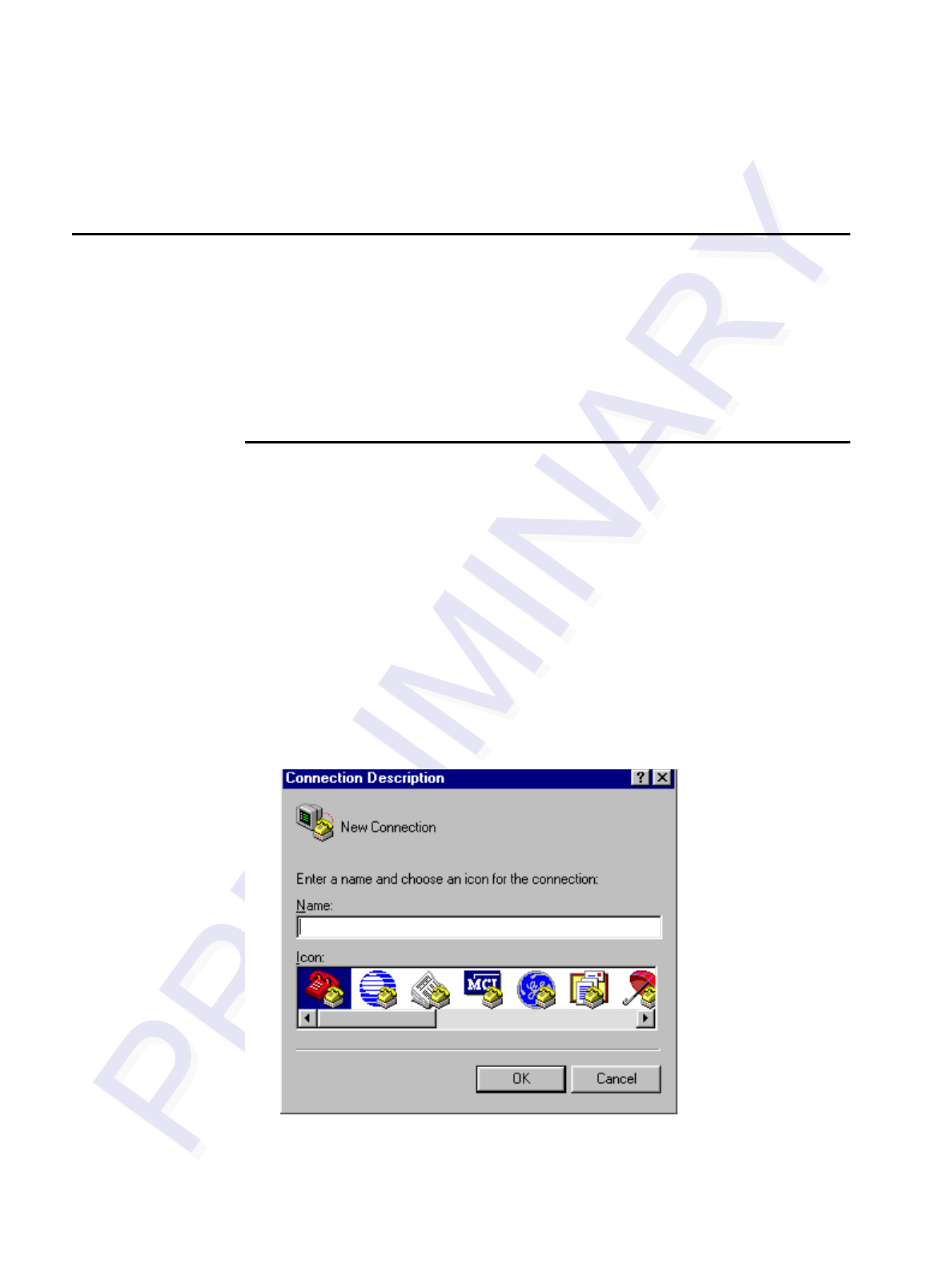
Encompass 4/4800 Multiprotocol Reader System Guide
8-6
Configuring Parameters with Terminal Emulation
Software
To configure the Encompass 4/4800 Multiprotocol Reader using a PC and terminal
emulation software to manually enter Encompass 4/4800 Multiprotocol Reader host
commands, follow the instructions in the section “Connecting the Encompass 4/4800
Multiprotocol Reader to the PC” on page 4-25. Then, enter the appropriate configura-
tion commands through the terminal emulation software on your PC.
See Chapter 7, “Commands,” for a detailed description of all available configuration
commands.
Starting the Terminal Emulation Software
You can use a PC and any terminal emulation software to enter the host commands to
download flash software, configure reader operating parameters, perform diagnostics,
and retrieve tag data. The following procedures show examples using Hyper Termi-
nal™, an application included with Microsoft Windows. Most terminal emulation
applications have a similar sequence for launching.
To start the terminal emulation software
1. At the command prompt, type your terminal emulation start command; or if
using Windows Hyper Terminal, select:
Programs>Accessories>Hyperterm
and press ENTER.
The application displays the Connection Description dialog box as shown in
Figure 8-1.
Figure 8-1 Connection Description Dialog Box
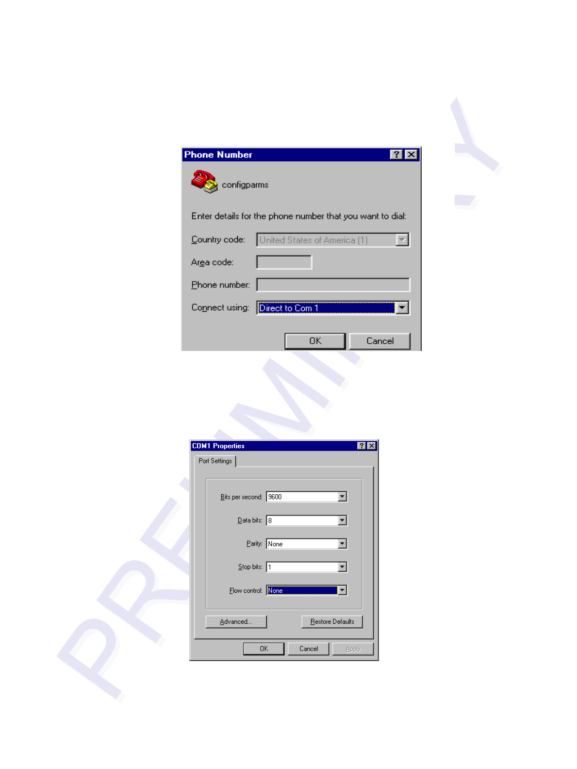
Configuring the Encompass 4/4800 Multiprotocol Reader
8-7
2. Enter a name for the session and click OK.
The application displays the Phone Number dialog box as shown in Figure 8-2.
Figure 8-2 Phone Number Dialog Box
3. From the Connect using pull-down list, choose the Com 1 option (or whichever
com port on the PC to which the RS-232 cable is attached) and click OK.
The application displays the COM1 Properties dialog box as shown in
Figure 8-3.
Figure 8-3 COM 1 Properties Dialog Box
4. In the pull-down lists on the COM1 Properties dialog box, choose the following
values:
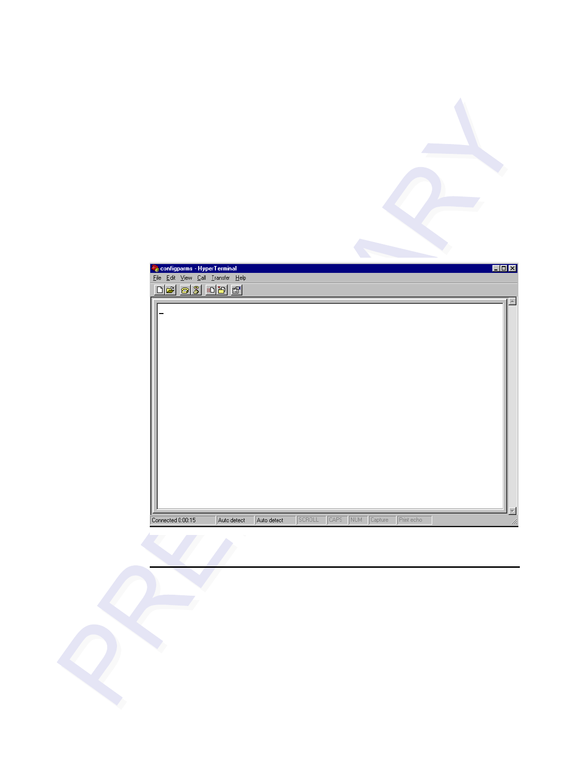
Encompass 4/4800 Multiprotocol Reader System Guide
8-8
•Bits per second: 9600 baud
•Data bits: 8
•Parity: None
•Stop bits: 1
•Flow control: None
Click OK.
The application displays the configparms - Hyper Terminal main screen as
shown in Figure 8-4.
Figure 8-4 Hyper Terminal Main Screen
Verifying Communications
You must verify that the Encompass 4/4800 Multiprotocol Reader and the PC or lap-
top are communicating.
To verify communications
1. Start the terminal emulation application as described previously in “Starting the
Terminal Emulation Software” on page 8-6.
Note: When testing the Encompass 4/4800 Multiprotocol Reader using a laptop,
TransCore recommends that you configure laptop communication parameters to
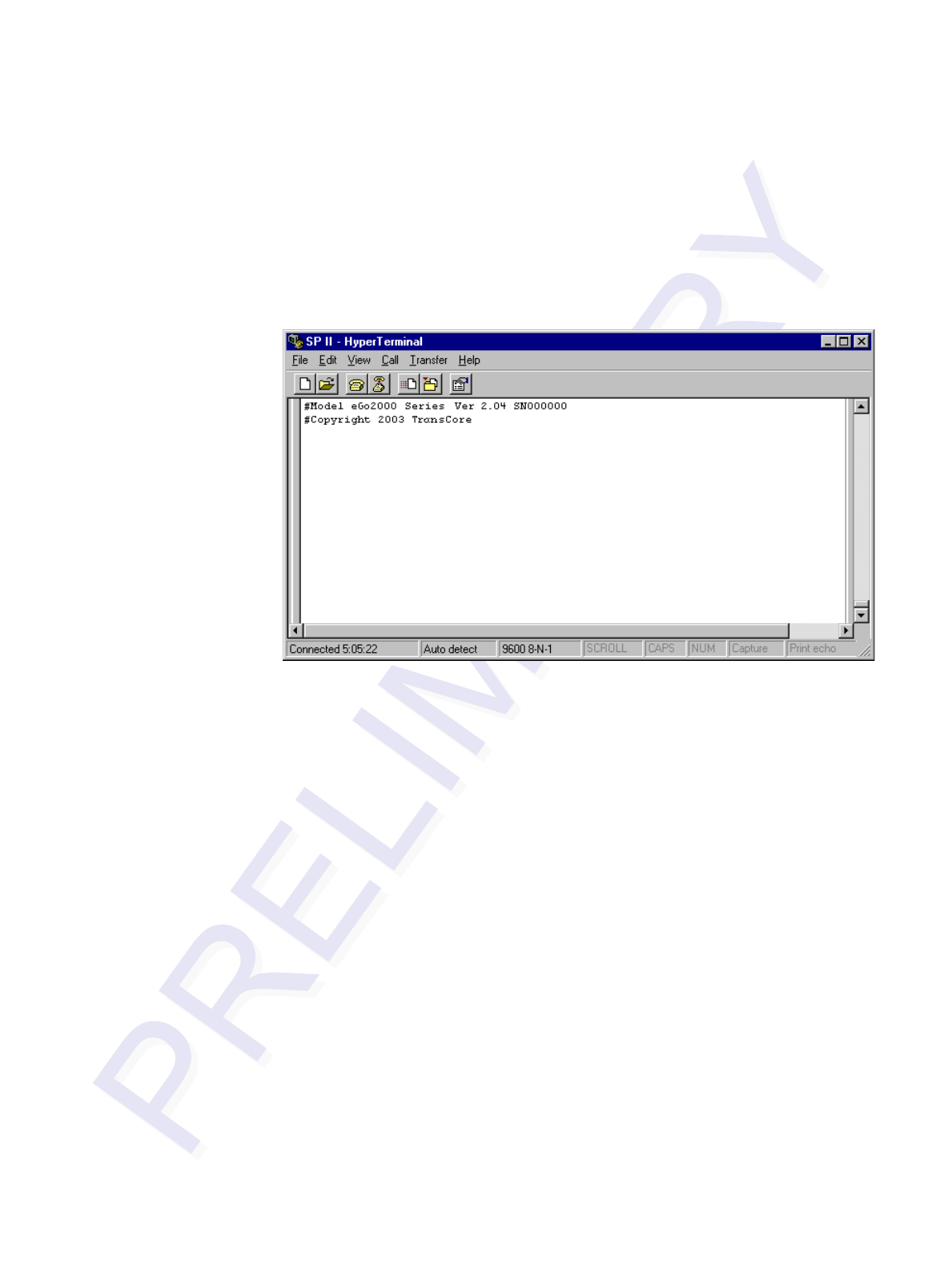
Configuring the Encompass 4/4800 Multiprotocol Reader
8-9
match those of the host computer to which the Encompass 4/4800 Multiprotocol
Reader will be connected after testing and configuration are completed.
2. Cycle the power on the Encompass 4/4800 Multiprotocol Reader.
Upon startup, the Encompass 4/4800 Multiprotocol Reader transmits a sign-on
message, displayed on the terminal emulation screen as shown in Figure 8-5, or a
boot ROM failure message.
Figure 8-5 Sign-on Message
The sign-on message appears as follows:
Model [software version] SNYYYYYY
[Copyright notice]
where YYYYYY is the serial number assigned to the Encompass 4/4800
Multiprotocol Reader skipping the fourth character printed on the reader product
label.
Serial number 000000 is the default setting and is not a valid number. If this
number appears in the sign-on message, the serial number has never been stored
into reader memory. Contact TransCore Technical Support.
If the flash memory checksum is not verifiable, the sign-on message appears as
follows:
Model [Model] Ver 0.00 E
[Copyright notice]
If the failure message version number equals 0.00 E and no serial number exists,
the flash memory checksum has failed, and the Encompass 4/4800 Multiprotocol
Reader is operating out of boot ROM. In this case, the Encompass 4/4800
Multiprotocol Reader automatically enters download mode and waits for a new
program to be loaded into the flash memory. Follow the instructions in “Program
Download” on page 5-5.

Encompass 4/4800 Multiprotocol Reader System Guide
8-10
Communications can also be verified by using the command sequence in
Table 8-3.
Table 8-3 Command Sequence to Verify Communications
3. If a successful sign-on message is not returned, check connections and
communications factors and correct any errors.
To check connections and communications factors
1. Confirm that the Encompass 4/4800 Multiprotocol Reader has power.
2. Verify the connections between the PC and the Encompass 4/4800 Multiprotocol
Reader.
3. Verify the receive (Rx) and transmit (Tx) connections.
4. If using handshaking, verify the RTS and CTS connections.
5. Verify the COM port settings for the Encompass 4/4800 Multiprotocol Reader
using the instructions in “Serial Port Communications” on page 8-18.
Repeat the procedures in “Verifying Communications” on page 8-8.
If you still cannot verify the Encompass 4/4800 Multiprotocol Reader and PC commu-
nications, use the information in “Technical Support” on page 9-7 to contact
TransCore.
Verifying Tag Read Capability
After verifying communications between the Encompass 4/4800 Multiprotocol
Reader and the PC, verify the capability to read tags.
Note: Default tag read mode of the reader is eATA. If test tags are standard ATA-pro-
tocol tags, change tag read mode of the reader by issuing command #47N Select Tag
Mode and using value #470 Dual 1.
Caution
To avoid damage to the Encompass 4/4800 Multiprotocol Reader using an external
antenna, you must connect the antenna before applying power to the reader.
Entry Encompass 4/4800
Multiprotocol Reader
Response Notes
#01 <CR> #Done <CR/LF> Switches the Encompass 4/4800
Multiprotocol Reader to command
mode.
#505 <CR> #Model eGo 2000 Ver X.0X
SN97001P <CR/LF> Reports the software version and
serial number.
#00 <CR> #Done <CR/LF> Returns the Encompass 4/4800
Multiprotocol Reader to data mode.
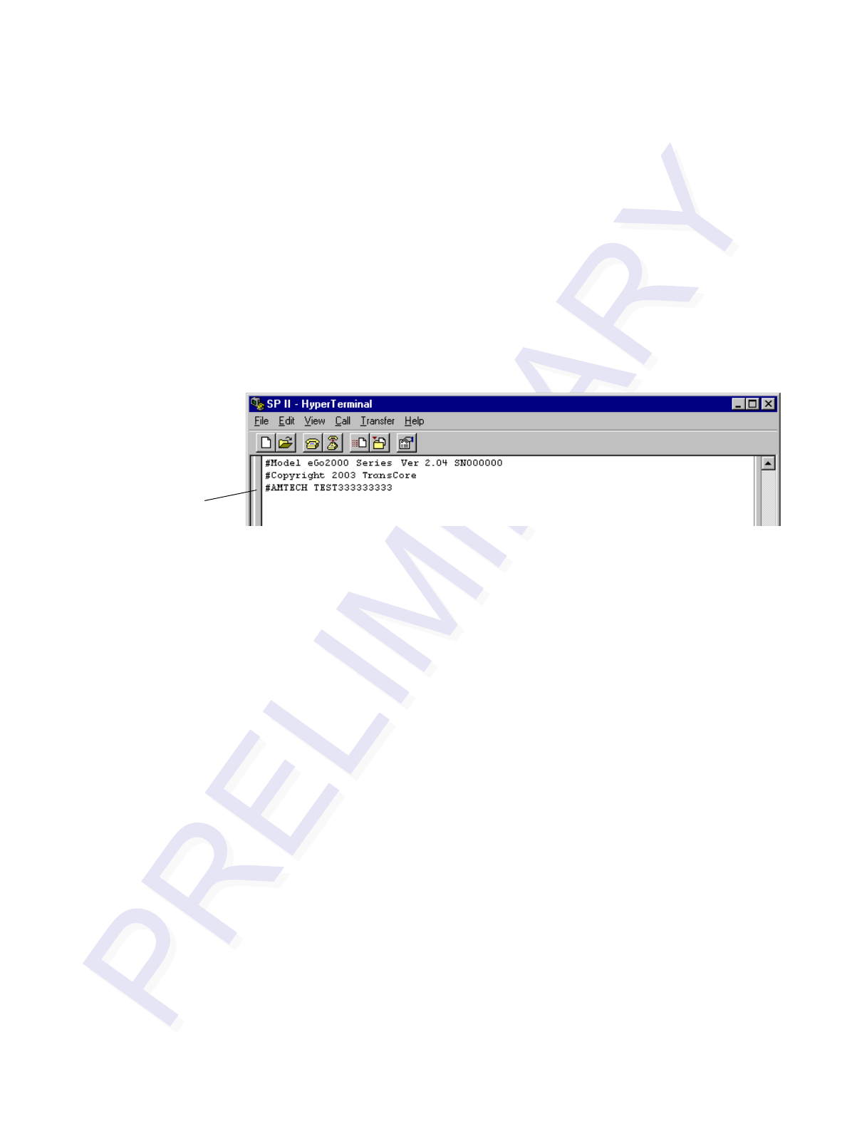
Configuring the Encompass 4/4800 Multiprotocol Reader
8-11
To verify tag read capability
1. Once communications are verified as described in “Verifying Communications"
on page 8-8, enter the following sequence of commands to turn on continuous
RF:
• #0121
• #6401
• #470
•#00
2. Pass one test tag in front of the unit. If the Encompass 4/4800 Multiprotocol
Reader reads the tag, the terminal emulation application displays the tag
information on the screen as shown in Figure 8-6.
Figure 8-6 Successful Tag Read
If the tag ID is not displayed, perform the following actions:
•Verify that the Encompass 4/4800 Multiprotocol Reader is in data
mode (command #00 Switch to Data Mode).
•Ensure that the tag you are using is compatible with the
Encompass 4/4800 Multiprotocol Reader. The Encompass 4/4800
Multiprotocol Reader has the capability to read the eGo
Windshield Sticker Tag as well as tags compliant with ATA and
ISO standards, including TransCore’s IT2000 tags with the ATA/
ISO mode enabled.
•A full-frame Encompass 4/4800 Multiprotocol Reader displays
either half or full-frame ATA-protocol tags. If you are using half-
frame Wiegand Windshield Sticker Tags, you might not see any
tag ID information displayed.
•Using the audible circuit tester as described in “Testing the
Encompass 4/4800 Multiprotocol Reader Using an Audible
Circuit Tester” on page 4-5, verify that the reader is capable of
reading the tag in the read zone. If it is, the problem is probably in
the communications between the Encompass 4/4800
Multiprotocol Reader and the host.
Successful
Tag Read
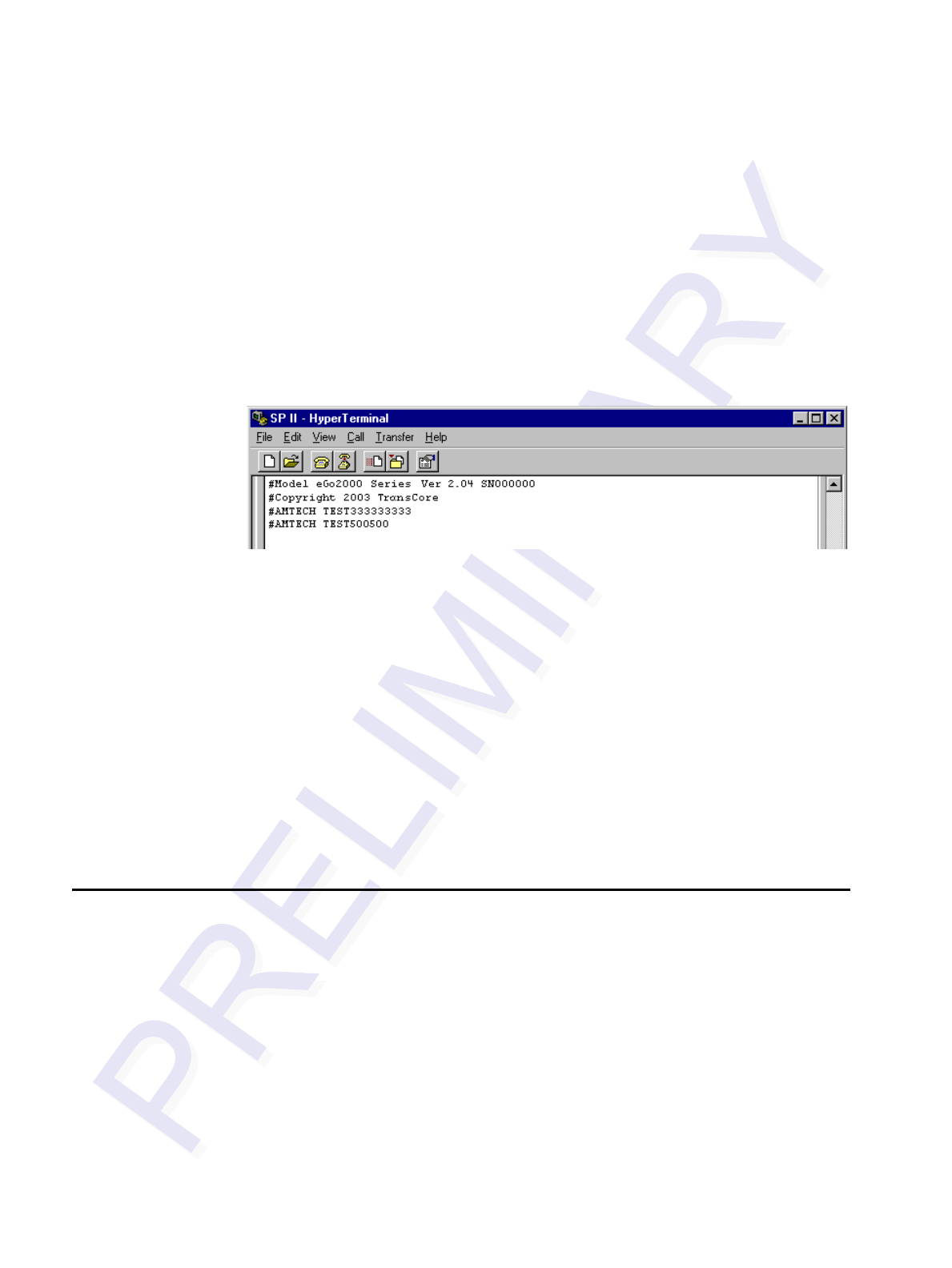
Encompass 4/4800 Multiprotocol Reader System Guide
8-12
3. Pass a different test tag in front of your Encompass 4/4800 Multiprotocol Reader.
Note: An internal timer in the Encompass 4/4800 Multiprotocol Reader causes
the reader to ignore a specific tag for two minutes or more after a good read
unless a different tag is read in the interim.The dual-protocol Encompass 4/4800
Multiprotocol internal timing varies depending on the operative tag read mode
and the type of tag in the read field.
4. When the Encompass 4/4800 Multiprotocol Reader reads the second tag
successfully, the terminal emulation application displays that tag’s information in
the main screen below the information for the first tag, as shown in Figure 8-7.
Figure 8-7 Second Successful Tag Read
If the read is unsuccessful, perform the following actions:
•Ensure the tag you are using is compatible with the Encompass 4/
4800 Multiprotocol Reader.
•Using the audible circuit tester as described in “Testing the
Encompass 4/4800 Multiprotocol Reader Using an Audible
Circuit Tester” on page 4-5, verify that the reader is capable of
reading the tag in the read zone. If it is, the problem is probably in
the communications between the Encompass 4/4800
Multiprotocol Reader and the host computer.
Configuring Encompass 4/4800 Multiprotocol Parame-
ters
Follow the procedures in this section to configure Encompass 4/4800 Multiprotocol
parameters using a PC, laptop, or terminal emulator. The PC or laptop must be con-
nected to and communicating with the Encompass 4/4800 Multiprotocol Reader, and
the terminal emulation application must be configured correctly, as described in the
section “Verifying Communications” on page 8-8.
Note: If you are using Wiegand mode, you must connect the PC or laptop to the
Encompass 4/4800 Multiprotocol Reader using the RS–232 or RS–422 interface
before attempting to send commands to the reader. You can leave the Wiegand inter-
face connected during this procedure.

Configuring the Encompass 4/4800 Multiprotocol Reader
8-13
To configure parameters
1. Switch to command mode by typing #01 at the prompt on the terminal
emulation screen, and pressing ENTER.
Note: All Encompass 4/4800 Multiprotocol Reader commands are preceded by the
start-of-message character (#).
2. To meet requirements of your site, make changes to default operating parameters
as described in the following sections.
The following sections contain procedures to set some of the parameters that are
commonly changed to meet the requirements of a specific site. Procedures are
listed in alphabetical order by parameter.
Appended Tag Data
Use this procedure to set appended tag data parameters using the terminal emulation
application. See “31N Append Auxiliary Information Selection” on page 7-10 for
more information.
To set appended tag data parameters
1. Ensure that the host computer is in command mode.
2. Enter command #311 to append auxiliary information or command #310 to
have no auxiliary information appended (factory default). Press ENTER.
ID Separation
The host can select a unique ID separation of one ID or two IDs. The uniqueness
timeout is fixed at two minutes. The reader default operation is for a unique ID separa-
tion of one ID and a uniqueness timeout of two minutes. You can disable the unique-
ness check using command #40 Transmit All ID Codes. In this case, every tag ID
received is transmitted without regard to uniqueness. You can reinstate uniqueness
checking with commands #4100 or #4101 Select ID Separation.
Note: The dual-protocol Encompass 4/4800 Multiprotocol Reader internal timing
varies depending on the operative tag read mode and the type of tag in the read field.
See section “40 Transmit All ID Codes” on page 7-11 and section “410N Select
Unique ID Code Criteria (Anti-passback Feature)” on page 7-11.
To set ID separation parameters
1. Ensure that the host computer is in command mode.
2. Enter command #4100 to select a separation of one ID; enter command #4101
to select a separation of two IDs. Press ENTER.

Encompass 4/4800 Multiprotocol Reader System Guide
8-14
Reports
The Encompass 4/4800 Multiprotocol Reader can be configured to transmit presence
without tag reports and input status change reports. A presence without tag report is
transmitted in data mode only, and only if the system has a presence detector. This
report is sent if a presence is detected without the detection of a valid tag ID. See sec-
tions “529 Display Presence Input Status” on page 7-23 and “690N Select Presence
Without Tag Report Option” on page 7-42.
If configured with command #82N Select Input Status Change Report Option to
transmit input status change reports, the reader will transmit a message to the host
computer any time the inputs change state. Input status change reports are transmitted
in data mode only. Input status change reporting is disabled by default. See sections
“560 Request Sensor Status Change” on page 7-27 and “82N Select Input Status
Change Report Option” on page 7-45. Also refer to Chapter 6, ”Communications Pro-
tocols” ” for information on message formats.
To set presence reporting
1. Ensure that the host computer is in command mode.
2. Enter command #529 to display presence input status and press ENTER. P0
indicates presence without tag reports disabled (factory default), and P1 indicates
presence without tag reports enabled.
3. Enter command #6901 to enable presence without tag reports, or enter
command #6900 to disable presence without tag reports (factory default). Press
ENTER.
To set input status change reporting
1. Ensure that the host computer is in command mode.
2. Enter command #560 to display input status change report options and press
ENTER.
• EO = input status change reports disabled (factory default)
• E1 = input status change reports enabled
• M0 = reporting disabled (factory default)
• M1 = changes on input0 reported
• M2 = changes on input1 reported
• M3 = changes on either input reported
3. Enter command #821 to report any change on input0, command #822 to report
any change on input 1, command #823 to report changes on input0 and input1,
or command #820 to disable status change reports (factory default). Press
ENTER.

Configuring the Encompass 4/4800 Multiprotocol Reader
8-15
Reset Reader
Command #63 Reset Reader resets uniqueness, clears the power fail bit, and trans-
mits the sign-on message. The reader returns to data mode following the completion
of this command.
Note: This command does not reset any of the configuration parameters.
See “63 Reset Reader” on page 7-34.
To reset the reader
1. Ensure that the host computer is in command mode.
2. Enter command #63. Press ENTER.
The terminal emulation screen displays the sign-on message as shown in Figure
8-5 on page 8-9.
Radio Frequency
Caution
The authorized frequency band for the Encompass 4/4800 Multiprotocol Reader in
the United States is 912.5 to 919 MHz. The RF for each Encompass 4/4800 Multi-
protocol Reader at the site must be set according to the frequency specified in the
FCC site license. Only trained, authorized installation and maintenance personnel
are permitted by FCC to set the RF.
By using the Encompass 4/4800 Multiprotocol Reader an authorized person can set
the frequency range from 902 to 928 MHz in 0.5 MHz steps. You can set the range by
using a terminal emulation program and issuing the frequency command, as discussed
in section “642NN Select RF Operating Frequency” on page 7-35.
To set the frequency range
1. Ensure that the host computer is in command mode.
2. Enter command #642NN – where NN is a hexadecimal value from 00 to 34 –
and press ENTER. See command “642NN Select RF Operating Frequency” on
page 7-35 for a complete listing of the hexadecimal values and the corresponding
frequencies.
3. To verify that the RF has been changed to the proper setting, type in command
#527 to see the current frequency setting.
Caution
Contact TransCore if your application requires a frequency outside of the autho-
rized frequency range.
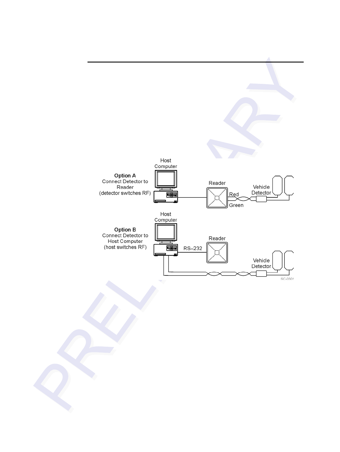
Encompass 4/4800 Multiprotocol Reader System Guide
8-16
RF Transmission
The RF transmission can be controlled by one of the following methods:
•Connecting a vehicle detector to the sense input0 circuit
•The host sending software commands to the Encompass 4/4800 Multiprotocol
Reader
As a factory default, the Encompass 4/4800 Multiprotocol Reader is configured to
control the RF power with a vehicle detector.
Figure 8-8 illustrates the methods of controlling RF sense output.
Figure 8-8 Encompass 4/4800 Multiprotocol Reader RF Control Options
Vehicle Detector Controlling RF Transmission
The vehicle detector can be a loop detector, an infrared sensor, or an ultrasonic detec-
tor that is connected to sense input0 to turn on the Encompass 4/4800 Multiprotocol
Reader RF transmitter. In Figure 8-8, Option A shows a vehicle detector controlling
the RF transmitter. This operation is preferred because the RF transmits only when a
vehicle is in the Encompass 4/4800 Multiprotocol Reader read zone. Command #641
Select RF-by-Input Control (factory default) must be enabled.
To set the option of the vehicle detector controlling the Encompass 4/
4800 Multiprotocol Reader
1. Ensure that the host computer is in command mode.
2. Enter command #641. Press ENTER.
Leave the setting on RF-by-input control for normal operation.

Configuring the Encompass 4/4800 Multiprotocol Reader
8-17
Host Controlling RF Transmission
In Figure 8-8, Option B shows the host controlling the RF transmitter.
If the vehicle detector is connected to the host computer, as shown in Option B, com-
mands #6400 RF Channel Off and #6401 RF Channel On sent from the host com-
puter turn on and off the Encompass 4/4800 Multiprotocol Reader RF transmitter.
Continuous RF Transmission
In Figure 8-8, Option C shows the test configuration controlling the RF transmitter. To
test the Encompass 4/4800 Multiprotocol Reader, as described in “Testing the Encom-
pass 4/4800 Multiprotocol Reader Using an Audible Circuit Tester” on page 4-5, you
can turn on the Encompass 4/4800 Multiprotocol Reader RF transmitter continuously
by issuing command #6401.
You may also use command #6402 to turn on continuous wave RF for diagnostic
purposes. Entering this command transmits a continuous RF signal at the output fre-
quency and attenuation level as specified in the respective associated commands until
command #6400 RF Channel Off, #6401 RF Channel On, or #641 Select RF-by-
Input Control is received by the reader. Tags are not read in continuous wave mode.
See “640N RF Control*” on page 7-34 for more information.
Sense Inputs
Both the RS–232 and RS–422 configurations used by the Encompass 4/4800 Multi-
protocol Reader have two sense inputs — sense input0 and sense input1. The default
configuration uses sense input0 as the presence detection device line. RF power is
automatically turned on only when the presence detection device (loop detector or
other device) detects a presence. Sense input1 is not used directly by the reader; it is
used by the host computer to monitor an external device. The Encompass 4/4800 Mul-
tiprotocol Reader sense inputs are designed to connect to a dry contact closure.
You can configure the Encompass 4/4800 Multiprotocol Reader to generate input sta-
tus change reports, which are transmitted like tag IDs. The host can then respond
based on the true/false (closed/open) status of the sense inputs. See the section
“Reports” on page 8-14.
The following procedures describe how to set sense inputs using the terminal emula-
tion software. See commands “526 Display I/O Status” on page 7-20, “694N Select
Input Inversion Option” on page 7-44, and “82N Select Input Status Change Report
Option” on page 7-45 for more information.
To set sense inputs
1. Ensure that the host computer is in command mode.
2. Enter command #526 to display the current input/output status. C0 = host
controls outputs; C1= predefined output mode; O0 = both outputs off; O1 =
output0 on; O2 = output1 on; O3 = both outputs on; I0 = both inputs false; I1 =
input0 true; I2 = input1 true.
3. Enter command #6940 to disable input inversion (factory default) or command
#6941 to enable input inversion, and press ENTER.

Encompass 4/4800 Multiprotocol Reader System Guide
8-18
Sense Output Devices
Both the RS–232 and RS–422 configurations used by the Encompass 4/4800 Multi-
protocol Reader have two sense output circuits – sense output0 and sense output1.
By default, the Encompass 4/4800 Multiprotocol Reader operates in predefined output
mode where sense output0 and sense output1 are asserted every time a unique valid
tag is read. Both sense output devices are asserted by issuing command #621 Pre-
defined Output Control. The devices are not asserted when tags are acquired in the
transmit all or buffer all ID mode or when the Encompass 4/4800 Multiprotocol
Reader is operating in Wiegand mode. The sense output pulse duration is variable
(command #67N).
The host computer can disable the predefined sense output control by issuing com-
mand #6201 to turn sense output0 on or by issuing any of the following commands:
#6200 Turn Off Both Output Ports, #6201 Turn Off Output0, On Output1, #6202
Turn Off Output1, On Output0, or #6203 Turn On Both Output Ports. While under
host control, the sense outputs are not automatically asserted when a valid tag is read.
The host must issue command #621Predefined Output Mode to return to the pre-
defined mode.
Serial Port Communications
The Encompass 4/4800 Multiprotocol Reader supports one communications port,
which can be ordered as either RS–232/Wiegand or RS–422/Wiegand. For the RS–
232 and RS–422 communications specifications, the Encompass 4/4800 Multiproto-
col Reader maintains the following three sets of parameters that affect serial port com-
munications:
•Port configuration parameters (baud rate, data bits, stop bits, parity)
•Communications protocols (basic, error correcting)
•Flow control scheme (none, software, hardware)
The default serial port configuration for each of these three parameters is as follows:
•9600 baud, 8 data bits, 1 stop bit, no parity
•Basic communications protocol
•Software flow control (XON/XOFF)
You can change these parameters in data mode and command mode operation by issu-
ing commands with the host computer. Use the following procedures to set serial port
communications parameters using the terminal emulation program.
Port Configuration Parameters
Use this procedure to set port configuration parameters using the terminal emulation
program. Consult sections “100N Select Baud Rate*" through “102N Select Parity”
on page 7-8.

Configuring the Encompass 4/4800 Multiprotocol Reader
8-19
To set baud rate
1. Ensure that the host computer is in command mode.
2. Enter command #100N and press ENTER.
To set stop bits
1. Ensure that the host computer is in command mode.
2. Enter command #101N and press ENTER.
To set parity
1. Ensure that the host computer is in command mode.
2. Enter command #102N and press ENTER.
Communications Protocol
Use the following procedures to set communications protocol. Consult sections “610
Enable Basic Communication Protocol (Factory Default)" through “612NN Select
Error Correcting Protocol Timeout” on page 7-30 for more information.
Caution
Do not switch to ECP (command #611) unless the host is prepared to acknowledge
each reader transmission.
To select a communications protocol
1. Ensure that the host computer is in command mode.
2. Enter command #610 to select basic protocol (factory default) or command
#611 to select ECP and press ENTER.
Software Flow Control
Two modes of flow control are supported — software (XON/XOFF) and hardware
(CTS - clear to send). The host can enable or disable flow control with command
#614N Select Flow Control Option.
The host can use software control characters (XON/XOFF) or the hardware CTS
handshake line to interrupt reader transmissions. When the reader is configured for
software flow control, it stops transmitting if it receives the XOFF character from the
host (host software command 13H). It resumes transmitting only when it receives the
XON character (host software command 11H) from the host. Likewise, when the
reader is configured for hardware flow control, it stops transmitting if it detects that
the CTS line is no longer asserted. It resumes transmitting when this line is asserted. If
flow control is not needed, the reader should be configured for no flow control
(#6140 Disable Flow Control).
Note: TransCore recommends that XON/XOFF flow control be disabled while using
the error correcting protocol.

Encompass 4/4800 Multiprotocol Reader System Guide
8-20
Use the following procedure to set flow control parameters using the terminal emula-
tion program. See section “614N Select Flow Control Option” on page 7-30.
To select flow control
1. Ensure that the host computer is in command mode.
2. Enter command #6140 to disable flow control, command #6141 to enable
software flow control (factory default), or command #6142 to enable hardware
flow control and press ENTER.
Fine-Tuning and Verifying the Read Zone
If the read zone is too wide or too deep for your application, it can be fine-tuned by
physically adjusting the Encompass 4/4800 Multiprotocol Reader or external antenna
mounting orientation, reprogramming the actual RF power output (#644NN Set RF
Attenuation), and/or reprogramming the RF sensitivity range (#643NN Select ATA
Operating Range and #645NN Select Encompass 4/4800 Multiprotocol Reader Oper-
ating Range). The combination of these adjustments allows you to confine the read
zone to the area where tagged vehicles pass. This operation also minimizes reading
unwanted vehicles in adjacent lanes or parking areas.
See sections “643NN Select ATA Operating Range (Distance)” on page 7-38, “645NN
Set Encompass 4/4800 Multiprotocol Reader Operating Range (Distance)**” on page
7-39, and “644NN Set RF Attenuation**” on page 7-38 for more information.
Note: As described in “Marking the Read Zone” on page 4-32, marking the read pat-
tern using test tags that are not mounted to vehicles give a general idea of the read
pattern but the pattern will vary somewhat when actual vehicles with tags are tested.
Final adjustments must be made with tags properly mounted on a variety of vehicles.
Physically Orienting the Encompass 4/4800 Multiprotocol
Reader
You can manually adjust the location of the read zone by loosening the Encompass 4/
4800 Multiprotocol Reader mounting brackets and pointing the reader in the desired
direction. The unit should be aligned to point directly at the tag as it enters the desired
read zone.
Physically Orienting the Encompass 4/4800 Multiprotocol
Reader Antenna
You can manually adjust the location of the read zone by loosening the antenna
mounting brackets and pointing the antenna in the desired direction. The unit should
be aligned to point directly at the tag as it enters the desired read zone.
Fine-Tuning the Read Zone by Lowering Output Power
You can make the read zone smaller by adjusting the Encompass 4/4800 Multiproto-
col Reader RF power output from a maximum of 2 watts to a minimum of 200 milli-
watts using command #644NN Set RF Attenuation. Lowering the RF power has the
added benefit of reducing RF interference with adjacent lanes.

Configuring the Encompass 4/4800 Multiprotocol Reader
8-21
To adjust the read zone by lowering output power
1. Ensure that your PC is communicating with the Encompass 4/4800 Multiprotocol
Reader using a terminal emulation program as described in section “Verifying
Communications” on page 8-8.
2. Mark the current read zone as described in section “Marking the Read Zone” on
page 4-32.
Caution
Test tags should be ATA-protocol, ISO-compliant tags, or eGo Windshield Sticker
Tags affixed to a piece of nonmetallic windshield-type glass 0.190 to 0.230 in (4.82
to 5.84 mm) in thickness. The eGo Windshield Sticker Tag has a reduced read range
when not attached to glass.
3. Enter command #01 to switch to command mode. You are prompted with
#DONE from the reader and can now enter reader commands.
4. Enter in command #64401 to lower the RF power by 1 dB below 2 watts
(default). Press ENTER.
Note: In the command #644NN, NN can be any hexadecimal value from 00 to
0A. Settings for attenuation are 1.0 dB increments over a range of 10 dB of atten-
uation from the maximum power setting of 2 watts at 0 dB attenuation to a mini-
mum power level of 200 milliwatts at 10 dB attenuation. Increasing the
attenuation lowers the output RF power.
5. Switch to data mode by entering command #00 and pressing ENTER.
6. Verify that the read zone has decreased by moving the tag through the desired
read area. If the read zone is still too large, switch to command mode and enter
the command #64402 to lower the output RF power another 1 dB. Continue
increasing the NN value until the read zone matches the desired read zone.
7. Follow the steps in “Procedures” on page 4-32 to mark the new read zone on the
ground with tape or chalk.
When the desired read zone is established, test the read zone with simulated and
real traffic by performing the following procedures:
To test the read zone
1. Ensure that the Encompass 4/4800 Multiprotocol Reader is in data mode.
2. With the Encompass 4/4800 Multiprotocol Reader running, place one tag behind
your back while you hold another tag in the new read zone. If a valid read, the
data from the tag held in the read zone displays on the PC screen.
3. Switch tags, placing the other tag behind your back and holding the first tag in
the read zone. If a valid read, the data from this tag held in the read zone displays
on the PC screen. If both tags are read, you have successfully adjusted the read
range.
4. If one or both tags did not read, follow the suggestions in “Verifying Tag Read
Capability” on page 8-10.
5. As a last test, attach test tags to vehicles and simulate traffic going through the
read zone to verify that the system performs accurately in a live environment.

Encompass 4/4800 Multiprotocol Reader System Guide
8-22
Fine-tuning the Read Zone by Adjusting Sensitivity Range
The Encompass 4/4800 Multiprotocol Reader read zone can be fine-tuned by using
command #643NN for ATA tag read mode or #645NN for Intellitag-based eGo tag
read mode to reprogram the RF sensitivity range. Sensitivity range adjustments have
less impact on the read pattern than RF power adjustment, thus RF power adjustment
should be used as the main read pattern adjustment tool. Sensitivity range control may
be helpful in stopping some tag reads on the very edges of the read pattern. To produce
a noticeable change in the read pattern, you must decrease the range sensitivity by
more than one increment.
To adjust the read zone by adjusting sensitivity range
1. Ensure that your PC is communicating with the Encompass 4/4800 Multiprotocol
Reader using a terminal emulation program as described in “Verifying
Communications” on page 8-8.
2. Mark the current read zone as described in “Marking the Read Zone” on page 4-
32.
3. Enter command #01 to switch to command mode. You are prompted with
#DONE from the reader and can now enter reader commands.
4. Enter command #64318 or #64518 to decrease the range sensitivity seven
increments below the maximum (default). Press ENTER.
Note: In the command #643NN or #645NN, NN can be any hexadecimal
value from 00 to 1F. The reader’s receiver becomes less sensitive to tag signals as
the value of NN is lowered from the maximum sensitivity of 1F to the minimum
sensitivity of 00.
5. Verify that the read zone has decreased by moving the tag through the desired
read area. If the read zone is still too large, switch to command mode and enter
the command #64317 or #64517 to decrease the range another increment.
Continue increasing the NN value until the read zone matches the desired read
zone.
6. Follow the steps in section “Procedures” on page 4-32 to mark the new read zone
on the ground with the tape or chalk.
When the desired read zone is established, test the read zone with simulated and
real traffic by performing the following procedures.
To test the read zone
1. Ensure that the Encompass 4/4800 Multiprotocol Reader is in data mode.
2. With the Encompass 4/4800 Multiprotocol Reader running, place one tag behind
your back while you hold another tag in the new read zone. If a valid read, the
data from the tag held in the read zone displays on the PC screen.
3. Switch tags, placing the other tag behind your back and holding the first tag in
the read zone. If a valid read, the data from this tag held in the read zone displays
on the PC screen.

Configuring the Encompass 4/4800 Multiprotocol Reader
8-23
4. If both tags are read, you have successfully adjusted the read range. If one or both
tags did not read, follow the suggestions in “Verifying Tag Read Capability” on
page 8-10.
5. As a last test, attach test tags to vehicles and simulate traffic going through the
read zone to verify that the system performs accurately in a live environment.

Encompass 4/4800 Multiprotocol Reader System Guide
8-24

9
Troubleshooting and Maintenance


9-3
Chapter 9
Troubleshooting and Maintenance
This chapter contains information for troubleshooting an EncompassTM
4/4800 Multiprotocol Reader and performing minimal maintenance
checks. It also includes information for returning products for repair,
obtaining support, and contact information for providing feedback and
suggestions to TransCore.
Error Messages
The Encompass 4/4800 Multiprotocol Reader transmits an error message if a com-
mand received from the host is not a recognized command or if information supplied
with the command is not correct. The reader sends this message to diagnostic com-
mands if the reader fails the specified test.
Table 9-1 contains a list of error messages.
Table 9-1 Error Messages
Error
Message Description Corrective Action
Error06 NVRAM parameters have been lost. The
Encompass 4/4800 Multiprotocol Reader
will not function properly because the RF
section is shut off until the frequency is
reset.
Reset the frequency using command
#642NN.
Error07 The RF phase locked loop (PLL) has lost
lock and is unable to operate at its
intended frequency. RF output is disabled
while the Encompass 4/4800 Multiprotocol
Reader attempts to reset the PLL.
Reset the RF frequency. Refer to “Radio
Frequency” on page 8-15 for instructions.
Error08 The RF PLL has successfully regained
lock and has been reset to its proper
operating frequency. The RF section is
returned to its state prior to losing lock
(enabled/disabled). Error08 will only be
issued after Error07 has been issued.
No action necessary; the previous error
has been corrected.

Encompass 4/4800 Multiprotocol Reader System Guide
9-4
Troubleshooting
You can use the following table for troubleshooting. Should problems continue, con-
tact TransCore for return and replacement procedures. If you call Technical Support,
use the symptom number in Table 9-2 to reference the problem that you are having
with the Encompass 4/4800 Multiprotocol Reader.
Error09 The Encompass 4/4800 Multiprotocol
Reader software has detected an old or
unsupported version of the Encompass 4/
4800 Multiprotocol Reader hardware and
will not function. The Encompass 4/4800
Multiprotocol Reader is immediately placed
into download mode after issuing this
message. This error can only occur on
system power-up or reset.
The correct version of the Encompass 4/
4800 Multiprotocol Reader software from
TransCore must be downloaded to the
Encompass 4/4800 Multiprotocol Reader.
Contact Technical Support as described on
page 9-7.
Error11 The operator is attempting to use an
Intellitag-based tag in Wiegand mode while
the Encompass 4/4800 Multiprotocol
Reader is in ID-only mode, thus Wiegand
compatibility issues.
Reset mode using command #473 for
Intellitag-based tags only or #470 for
Intellitag-based/ATA tags.
Table 9-1 Error Messages (continued)
Error
Message Description Corrective Action
Table 9-2 Symptoms and Remedies
Symptom
NumberaSymptom Remedy
1 When performing a quick
test of the Encompass 4/
4800 Multiprotocol Reader,
the buzz box does not buzz.
Check all your wiring connections and antenna connections (if
using external antenna), and ensure that your buzz box is
functioning.
The wires from the Encompass 4/4800 Multiprotocol Reader
are grouped in pairs. You could find more than one red wire,
more than one black wire, and so on. You must connect the
correct red and white wire pair to the leads from the battery.
Verify that RF is on as described in “Bench Testing the
Encompass 4/4800 Multiprotocol Reader Before Installation”
on page 4-12. Using a terminal emulation program, you may
switch to command mode and issue command #527 to
determine RF status. See page 7-22 for more information.
2 The baud rate is selected
correctly but nothing
happens.
The Encompass 4/4800 Multiprotocol Reader is not
communicating with your PC. Check the power supply to your
PC, and check the connections between the PC and the
Encompass 4/4800 Multiprotocol Reader. Try reversing the
receive and transmit connections.

Troubleshooting and Maintenance
9-5
3 When testing the
Encompass 4/4800
Multiprotocol Reader, all the
wires are connected
correctly but the unit does
not respond.
The Encompass 4/4800 Multiprotocol Reader may not have
the software loaded inside the unit. Contact Technical Support
as described on page 9-7.
If you are using a terminal emulation program, check that the
terminal emulation setting on the Encompass 4/4800
Multiprotocol Reader is VT100.
Check that the Encompass 4/4800 Multiprotocol
communication cable is connected to the correct COM port.
Verify that the external antenna is connected correctly.
Verify that the reader is in the correct tag read mode (#47N).
4 Strange signal responses
come from the Encompass
4/4800 Multiprotocol Reader
when tested with the PC.
Ensure that the reader is in the correct interface mode for the
test tag, i.e., Wiegand mode for a Wiegand tag.
Check the system defaults using a terminal emulation
program. Both PC and reader should be set to 9600 baud, 8
bits, 1 stop bit, and no parity.
5 When a tag is moved in front
of the reader or external
antenna, a clicking sound
comes from the Encompass
4/4800 Multiprotocol
Reader.
The Encompass 4/4800 Multiprotocol Reader works! The
sound is the relay inside the Encompass 4/4800 Multiprotocol
Reader that is controlled by a lock signal. The relay is
actuated when a tag is in the read zone.
6 Nothing happens when the
test tag is passed in front of
the Encompass 4/4800
Multiprotocol Reader or
external antenna.
Ensure that the Encompass 4/4800 Multiprotocol Reader is
powered on and is in predefined output mode. (#621)
Verify that the reader is in the correct tag read mode (#47N).
Verify that the reader is set to RF ON (#6401).
Verify that the external antenna is connected correctly.
7 The Encompass 4/4800
Multiprotocol Reader came
from another site and does
not work the way the factory
defaults indicate that it
should.
Different commands were probably used to support the other
site’s specific configuration. You can restore the factory
defaults by using a terminal emulation program to switch to
command mode and issuing command #66F Load Default
Operating Parameters. All factory defaults except RF
frequency will be restored.
8 When connected to a PC
that is running terminal
communications software, a
just-powered up Encompass
4/4800 Multiprotocol Reader
displays one of the following
messages:
#TBD Ver X SNYYYYYY
#[Copyright notice]
The Encompass 4/4800 Multiprotocol Reader works! The
software is now loaded. YYYYYY is the TransCore-assigned
serial number for this Encompass 4/4800 Multiprotocol
Reader. However, if YYYYYY = 000000, a serial number has
never been assigned. If a serial number has not been
assigned to your Encompass 4/4800 Multiprotocol Reader,
contact TransCore Technical Support. Note that each
Encompass 4/4800 Multiprotocol unit must have its own
unique serial number.
Table 9-2 Symptoms and Remedies (continued)
Symptom
NumberaSymptom Remedy

Encompass 4/4800 Multiprotocol Reader System Guide
9-6
aUse this number to reference the problem you are having with the Encompass 4/4800 Multiprotocol Reader
if you call Technical Support.
Encompass 4/4800 Multiprotocol Reader Repair
The Encompass 4/4800 Multiprotocol Reader is designed for whole-unit replacement
and is manufactured with surface-mounted components. It requires sophisticated test-
ing and repair equipment. All testing and repairs are performed at TransCore’s factory.
Please contact TransCore to obtain a Return Materials Authorization (RMA) for
returning the reader.
9 The read zone is too small,
even before the RF power
and range control have been
adjusted.
If another Encompass 4/4800 Multiprotocol Reader is in the
same area, ensure that it is operating on another frequency
that is at least 2 MHz different.
Check for possible interference from another nearby RF
source: fluorescent lights, neon signs, high voltage power
lines, nearby cellular telephone, or radio stations. Lights will
need to be removed or shielded. Point the Encompass 4/4800
Multiprotocol Reader or external antenna in a different
direction to see if interference comes from only one direction.
You may require a different Encompass 4/4800 Multiprotocol
Reader that uses another frequency.
Verify that the RF power is set to an appropriate value.
Verify that the range adjustment is set to the maximum.
Verify that the reader is getting at least 16V.
10 The perimeter of the read
zone has been defined, but
there is a “hollow” spot in the
center of the zone that does
not read tags.
The angle of the Encompass 4/4800 Multiprotocol Reader or
external antenna may need adjustment. Slightly tilt the
Encompass 4/4800 Multiprotocol Reader or external antenna
to a different angle to change either the length or width of the
read zone.
Check the range control adjustment. See “Radio Frequency”
on page 8-15.
11 The Encompass 4/4800
Multiprotocol Reader is
reading tags out of the
desired read zone, or cross-
lane reads are occurring.
Some interference from other RF or electrical sources may be
occurring. See “Reflection, Refraction, and Diffraction of RF
Signals” on page 2-19.
Verify that the read zone has been properly set up. See “Fine-
Tuning and Verifying the Read Zone” on page 8-20.
12 The Encompass 4/4800
Multiprotocol Reader is not
providing any output to the
Wiegand interface.
Ensure that the Encompass 4/4800 Multiprotocol Reader is in
Wiegand mode (#451). The default is either RS–232 or RS–
422 mode. Refer to “Wiegand Interface” on page 4-28.
Ensure the tags are properly programmed with Wiegand data.
Table 9-2 Symptoms and Remedies (continued)
Symptom
NumberaSymptom Remedy

Troubleshooting and Maintenance
9-7
Technical Support
Authorized dealers and distributors are responsible for the direct support of all cus-
tomers. Authorized dealers and distributors needing support can call
(800) 755-0378 and ask for Technical Support, which is available 24 hours a day. Send
faxes to (214) 461-6478 ATTN: Technical Support. Please be prepared to answer a
series of questions that are designed to direct you to the best TransCore support
resource available. These questions will relate to symptoms, configuration, model,
and tags used.
Note: End users and facility operators calling Technical Support will be referred to
the dealer responsible for the system sale.
Marketing Support
Dealers requiring marketing support may call TransCore Marketing at
(214) 461-4031, 9:00 a.m. to 5:00 p.m. Central Standard Time, Monday through Fri-
day. Send faxes to (214) 461-6478 ATTN: TransCore Marketing.
Find a Problem with the Encompass 4/4800 Multiprotocol
Reader or Have Suggestions?
Call (800) 755-0378, which is answered 24 hours a day, and ask for the TransCore
Encompass 4/4800 Multiprotocol Reader product manager. Send faxes to (214) 461-
6478 ATTN: Encompass 4/4800 Multiprotocol Reader product manager.

Encompass 4/4800 Multiprotocol Reader System Guide
9-8

A
Glossary


A-3
Appendix A
Glossary
A
AAR Association of American Railroads
AC alternating current
ACK acknowledge (data valid)
ANSI American National Standards Institute
antenna passive device that converts RF energy into magnetic energy (RF signal)
ASCII American Standard Code for Information Interchange
ASIC application-specific integrated circuit
ATA American Trucking Association
aux auxiliary
AWG AWG (American Wire Gauge) is a U.S. standard set of non-ferrous wire conductor
sizes
B
backscatter portion of an RF signal that is modulated by a tag and radiated back to the reader
baud measure of number of bits per second of a digital signal; for example, 9600 baud =
9600 bits per second
BCKS boot checksum
BCM buffer control mode
bps bits per second
byte a binary character; for example, one 8-bit ASCII character
C
check tag tag mounted inside a reader assembly, inside or in close proximity to an external
antenna that is used to check operation of the reader

Encompass 4/4800 Multiprotocol Reader System Guide
A-4
cmd command
CTRL control
comm communications
command data set that is recognized by the receiving device as intending to elicit a specific
response
conduit flexible steel pipe use for electrical wiring
cps characters per second
CR carriage return
CRC cyclic redundancy check
CTS clear to send
D
data information that is processed by a computing device
DC direct current
DIAG diagnostic
E
ECP error correcting protocol
ECPS error correcting protocol status
eGo proprietary name for ANS INCITS 256-2001 compliant TransCore tag products. A
registered trademark of TCP IP, Ltd.
Encompass proprietary name for ANS INCITS 256-2001 compliant TransCore reader products. A
trademark of TC IP, Ltd.
eol end of line
eom end of message
EPROM erasable programmable read-only memory

Glossary
A-5
F
field physical area/space in which a tag can be read by the reader; also, an element of a data
record/frame. For example, division within a tag's data frame.
frames consecutive bits of data in memory that are read and written as a group
frequency bands a range of RF frequencies assigned for transmission by an RF device
H
hex hexadecimal
hexadecimal base 16 numbering system that uses the characters 0 though 9 and A through F to
resent the digits 0 through 16
host device, generally a computer, that is connected to the Encompass 4/4800 Multiproto-
col Reader through the communications port
I
I/O or IO circuits input/output circuits
ID identification; encoded information unique to a particular tag
INCITS American National Standards Institute International Committee for Information
Technology standards
Intellitag Proprietary name for ANS INCITS 256-2001 compliant Intermec products. A
registered trademark of Intermec Technologies Corporation, a UNOVA Company.
interface connection point for communication with another device
IOST I/O status
ISO International Standardization Organization
L
LF line feed
M
mmeter

Encompass 4/4800 Multiprotocol Reader System Guide
A-6
MHz megahertz
mode method of operation
ms milliseconds
N
NAK negative acknowledgment (data not valid)
P
passback used to refer to a tag ID that is not passed on to the tag buffer
PC personal computer
PCKS EPROM flash checksum
protocol specified convention for the format of data messages communicated between devices
PRST presence status
PWRB power fail bit
R
RAM random access memory
RDID reader ID
read process of acquiring data from a device; for example, from a tag or from computer
memory
reader controlled interrogating device capable of acquiring data from a device; for example,
acquiring and interrupting data from a tag
read zone the physical area in which a tag can be read by the reader
RF radio frequency
RFST RF status
RFID radio frequency identification
ROM read-only memory
RTC real-time clock

Glossary
A-7
RTS request-to-send
S
SCTS status of check tag status
SSTC input status change reporting options
som start of message
SN serial number
T
tag small self-contained device acting as an identifying transponder
Tau timeout delay
TT tag translation
V
Vvolts
Ver version (software)
W
Wiegand the trade name for a technology used in card readers and sensors, particularly for
access control applications. Wiegand devices were originally developed by HID
Corporation.
write process of recording data; for example, writing to computer memory or to a tag’s
memory. Writing writes over (erases) previous data stored at the specified memory
locations.
WTI Wiegand retransmit interval

Encompass 4/4800 Multiprotocol Reader System Guide
A-8
X
XON/XOFF protocol for controlling the flow of data between computers and other devices on an
asynchronous serial connection. X/ON and X/OFF are signals to turn a transmitter on
or off. The actual signal for X/ON is the same bit configuration as the ASCII Ctrl-Q
keyboard combination (11 hexadecimal). The X/OFF signal is the Ctrl-S character (13
hexadecimal).

B
Technical Specifications


B-3
Appendix B
Technical Specifications
Reader Specifications
Communications
Hardware Features
Power Requirements
Frequency Selection 902 to 928 MHz capable
912.5 to 919 MHz FCC-authorized in the United
Statesa
a. Operation in the United States is regulated by the FCC. Local
regulations apply. The user is required to obtain a license issued
by the FCC. Contact TransCore for more information.
Reading Range Read performance varies depending on tag,
reader, and external antenna (if required) config-
uration and environment. Optimum read range
using the eGo Windshield Sticker Tag is 24.3 ft
(7.4 m).
Typical read range should be 12 to 17 ft (3.7 to
5.2 m).b
b. Reading range depends on reader or external antenna configu-
ration, tag type, tag read mode, and operating environment.
Integrated System
and/or integrated sys-
tem with connector for
external antenna
RF module, tag decoder, external antenna (if
required), power supply, I/O ports, and serial
communications interface all housed in a single
package.
Case Weatherproof enclosure. The system is sealed in
a tamper-proof, polycarbonate housing.
Input Voltage 16 to 20V AC, 47 to 63 Hz
or
16 to 28V DC

Encompass 4/4800 Multiprotocol Reader System Guide
B-4
Physical Attributes
Environmental Parameters
Options
Size 15.5 x 15.5 x 3.25 in (39.4 x 39.4 x 8.25 cm)
Weight 9.5 lb (4.3 kg)
Operating Temperature -40°F to +131°F
(-40°C to +55°C)
Humidity 100% noncondensing
Vibration Tolerance 0.5 Grms, 10 to 500 Hz
Communications Interface RS–232 and Wiegand or RS–422 and Wiegand
Cable Accessory Kits 58-1620-001: Connector with 5 ft (1.5 m) cable
58-1620-002: Connector with 20 ft (6.1 m) cable
58-1620-006: Connector with 35 ft (10.7 m)
cable
Wall Mount Bracket Allows adjustment in all planes when used to
install the Encompass 4/4800 Multiprotocol
Reader on a flat surface. Include the part number
54-1620-001 when ordering.
Transformer A Class C transformer is available to allow 110V
AC to 18V AC conversion.
Include the part number 76-1620-005 when
ordering.
A Class C transformer (part number 76-1620-
008) to allow 220V AC to 18V AC conversion is
available by special request.

C
Wiring Tables


C-3
Appendix C
Wiring Tables
This appendix contains tables that show the wiring connections used to
test and install the EncompassTM 4/4800 Multiprotocol Reader.
Communications Interfaces
Table C-1 lists the interfaces available with the Encompass 4/4800 Multiprotocol
Reader.
Figure C-1 shows the pin assignments for the RS–232 interface signal to the host male
DB9 and DB25 connectors.
Table C-1 Communications Interfaces and Conductor Requirements
Interface Number of
Conductors
RS–232 3
RS–232 with RTS and CTS hardware handshake signals 5
RS–422 4
Wiegand 3
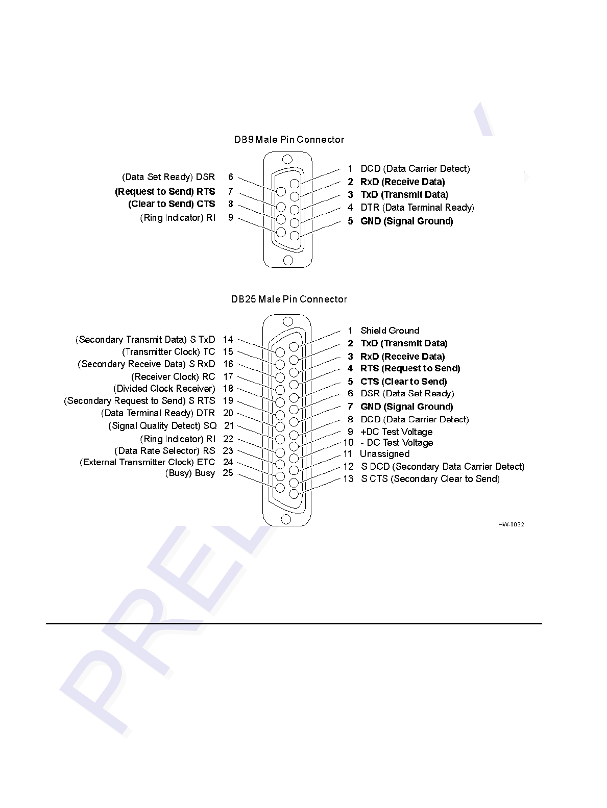
Encompass 4/4800 Multiprotocol Reader System Guide
C-4
Figure C-1 DB9 and DB25 Connector Pin Assignments for Signal to Host
Note: In Figure C-1, supported pin assignments are boldface.
Cable Supplied with the Encompass 4/4800 Multiprotocol
Reader
The Encompass 4/4800 Multiprotocol Reader is delivered with a multiwire cable
(ordered as a separate accessory), which is a 13-pair pigtail. An alternate 15-pair pig-
tail may be substituted. The 13-pair pigtail is a colored-wire pair cable, with different
colors denoting the individual pairs, one pair of which is red/black. The alternate 15-
pair pigtail is a red/black-wire pair cable, with numbers on the pairs to denote the indi-
vidual pairs. Two pairs of the 15-pair pigtail, numbers 14 and 15, are not used.

Wiring Tables
C-5
The following tables show the colored-wire pair (13-pair) and alternate wire pair
(15-pair) assignments for the various interfaces, power, and input/output connections.
RS–232 Interface
Table C-2 shows the RS–232 assignments for colored-wire pair (13-pair) cable.
Table C-2 RS–232 Interface Signal Wiring for Colored-Wire Pair Cable
Signal from
Encompass
4/4800
Multiprotocol
Reader
Colored-Wire Pair Cable
Connect
Wire to
Host DB9
Pin
Connect
Wire to
Host DB25
Pin
Wire Pair
from
Encompass
4/4800
Multiprotocol
Reader
Color Used
TxD —
Encompass
4/4800
Multiprotocol
Reader output Red/Black
Black Pin 2 Pin 3
RxD —
Encompass
4/4800
Multiprotocol
Reader input
Red Pin 3 Pin 2
Signal ground Yellow/Black Yellow or
Black Pin 5 Pin 7
Optional for hardware handshaking
RTS —
Encompass
4/4800
Multiprotocol
Reader output Yellow/Red
Yellow Pin 8 Pin 5
CTS —
Encompass
4/4800
Multiprotocol
Reader input
Red Pin 7 Pin 4

Encompass 4/4800 Multiprotocol Reader System Guide
C-6
Table C-3 shows the RS–232 assignments for alternate wire (15-pair) cable.
RS–422 Interface
Table C-4 shows the RS–422 assignments for colored-wire pair (13-pair) cable.
Table C-3 RS–232 Interface Signal Wiring for Alternate Wire Cable
Signal from
Encompass 4/4800
Multiprotocol Reader
Alternate Wire Cable Connect
Wire to
Host DB9
Pin
Connect
Wire to
Host DB25
Pin
Pairing Color
TxD — Encompass
4/4800 Multiprotocol
Reader output Pair 1
Black Pin 2 Pin 3
RxD — Encompass
4/4800 Multiprotocol
Reader input
Red Pin 3 Pin 2
Signal ground Pair 5 Black or
Red Pin 5 Pin 7
Optional for hardware handshaking
RTS — Encompass
4/4800 Multiprotocol
Reader output Pair 11
Black Pin 8 Pin 5
CTS — Encompass
4/4800 Multiprotocol
Reader input
Red Pin 7 Pin 4
Table C-4 RS–422 Interface Signal Wiring for Colored-Wire Pair Cable
Signal from Encompass
4/4800 Multiprotocol Reader
Colored-Wire Pair Cable
Connect to
Signal from
Host
Wire Pair
from
Encompass
4/4800
Multiprotocol
Reader
Color Used
RS–422 Transmit positive Yellow/Red Yellow Receive (+)
RS–422 Transmit negative Red Receive (–)
RS–422 Receive positive Red/Black Black Transmit (+)
RS–422 Receive negative Red Transmit (–)

Wiring Tables
C-7
Table C-5 shows the RS–422 assignments for alternate wire (15-pair) cable.
Wiegand Interface
Table C-6 shows the Wiegand assignments for colored-wire pair (13-pair) cable.
Signal Ground Yellow/Black Yellow or
Black Signal Ground
Table C-5 RS–422 Interface Signal Wiring for Alternate Wire Cable
Signal from Encompass
4/4800 Multiprotocol Reader
Alternate Wire Cable Connect to
Signal from
Host
Pairing Color
RS–422 Transmit positive Pair 11 Black Receive (+)
RS–422 Transmit negative Red Receive (–)
RS–422 Receive positive Pair 1 Black Transmit (+)
RS–422 Receive negative Red Transmit (–)
Table C-6 Wiegand Interface Signal Wiring for Colored-Wire Pair Cable
Signal from Encompass
4/4800 Multiprotocol
Reader
Colored-Wire Pair Cable
Connect to
Signal from
Host
Wire Pair from
Encompass
4/4800
Multiprotocol
Reader
Color Used
Wiegand Zero Output Blue/Red Blue Data0
Wiegand One Output Red Data1
Signal Ground Yellow/Black Yellow or Black Ground
Table C-4 RS–422 Interface Signal Wiring for Colored-Wire Pair Cable

Encompass 4/4800 Multiprotocol Reader System Guide
C-8
Table C-7 shows the Wiegand assignments for alternate wire (15-pair) cable.
Power Supply Connections
AC Power
Table C-8 shows the colored-wire pair (13-pair) assignments for connection to a low-
voltage AC power supply.
Table C-7 Wiegand Interface Signal Wiring for Alternate Wire Cable
Signal from Encompass
4/4800 Multiprotocol
Reader
Alternate Wire Cable
PairingColor
Connect to
Signal from
Host
Wiegand Zero output Pair 10 Black Data0
Wiegand One output Red Data1
Signal Ground Pair 5 Black or Red Ground
Table C-8 AC Transformer Connections for Colored-Wire Pair Cable
Signal From Encompass
4/4800 Multiprotocol
Reader
Colored-Wire Pair Cable
Connect to
Transformer
Terminal Strip
Wire Pair from
Encompass
4/4800
Multiprotocol
Reader
Color Used
Main power input
Brown/Red and
Orange/Red
Brown/
Orange L1
16-20 V AC
Main power return Red/Red L2
16-20 V AC

Wiring Tables
C-9
Table C-9 shows the alternate wire (15-pair) assignments for connection to a low-volt-
age AC power supply.
Low-Voltage DC Power
Table C-10 shows the colored-wire pair (13-pair) assignments for connection to a low-
voltage DC power supply.
Table C-11shows the alternate wire (15-pair) assignments for connection to a low-
voltage DC power supply.
Table C-9 AC Transformer Connections for Alternate Wire Cable
Signal from Encompass
4/4800 Multiprotocol
Reader
Alternate Wire Cable Connect to
Transformer
Terminal
Strip
Pairing Color
Main power input
Pair 12 and
Pair 13
Black/Black L1
16-20 V AC
Main power return Red/Red L2
16-20 V AC
Table C-10 Low Voltage DC Cable Connections for Colored-Wire Pair Cable
Signal from
Encompass
4/4800
Multiprotocol
Reader
Colored-Wire Pair Cable
Connection Use
Wire Pair
from
Encompass
4/4800
Multiprotocol
Reader
Color Used
Main power input Brown/Red
and
Orange/Red
Brown and
Orange 16 to 28 V DC + terminal
Main power return Red and
Red 16 to 28 V DC – terminal
Table C-11 Low Voltage DC Cable Connections for Alternate Wire Cable
Signal from
Encompass 4/4800
Multiprotocol
Reader
Alternate Wire Cable
Connection Use
Pairing Color
Main power input Pair 12 and
Pair 13
Black and
Black 16 to 28 V DC + terminal
Main power return Red and Red 16 to 28 V DC – terminal

Encompass 4/4800 Multiprotocol Reader System Guide
C-10
Input/Output Cabling Assignments
Table C-12 shows the sense input/output assignments for colored-wire pair (13-pair)
cable.
Table C-12 Sense Input/Output Cabling Assignments for Colored-Wire Pair Cable
Pair Pin Color Signal Description Typical Function
Blue/
Red E Blue WGND0 Wiegand data0 Parking/access
control
applications
F Red WGND1 Wiegand data1 Parking/access
control
applications
White/
Red L White Lock Tag lock output,
active-closed Testing
maintenance
M Red Lock_RTN Tag lock return Testing
maintenance
Green/
Red N Green Sense Input0 Sense Input0
(loop), active-
closed
Loop and
presence detection
P Red Sense
Input0_RTN Sense Input0
return; not
isolated from
signal ground
Loop and
presence detection
Blue/
Black R Blue Sense Input1 Sense Input1,
active-closed General-purpose
sense input, not
used to detect
presence
S Black Sense
Input1_RTN Sense Input1
return; not
isolated from
signal ground
General-purpose
sense input, not
used to detect
presence
Brown/
Black T Black Sense
Output0_COM Sense Output0
(tag detect),
common terminal
Switched output to
control gate
U Brown Sense
Output0_NO Sense Output0,
normally open
terminal
Switched output to
control gate
Orange/
Black V Black Sense
Output0_COM Sense Output0
(tag detect
output), common
terminal
Switched sense
output for any
external control
(light, gate, buzzer,
etc.)

Wiring Tables
C-11
Table C-13 shows the sense input/output assignments for alternate wire (15-pair)
cable.-
W Orange Sense Output
0_NC Sense Output0,
normally closed
terminal
Switched sense
output for any
external control
(light, gate, buzzer,
etc.)
Green/
Black X Black Sense
Output1_ COM Sense Output1,
common terminal Switched sense
output
Y Green Sense
Output1_NO Sense Output1,
normally open
terminal
Switched sense
output
White/
Black Z Black Sense
Output1_COM Sense Output1,
common Switched sense
output
a White Sense
Output1_NC Sense Output1,
normally closed
terminal
Switched sense
output
Yellow/
Black b Yellow GND logic ground Signal ground
(used with RS–
232 and Wiegand
communications)
c Black GND logic ground Signal ground
(used with RS–
232 and Wiegand
communications)
Table C-12 Sense Input/Output Cabling Assignments for Colored-Wire Pair Cable
Pair Pin Color Signal Description Typical Function
Table C-13 Sense Input/Output Cabling Assignments for Alternate Wire Cable
Alternate Wire Cable Signal Description Typical Function
Pairing Pin Color
Pair 10 E Black WGND0 Wiegand data0 Parking/access
control applications
F Red WGND1 Wiegand data1 Parking/access
control applications
Pair 8 L Black Lock Tag lock sense
output, active-
closed
Testing maintenance
M Red Lock_RTN Tag lock return Testing maintenance

Encompass 4/4800 Multiprotocol Reader System Guide
C-12
Pair 9 N Black Sense Input0 Sense Input0
(loop), active-
closed
Loop and presence
detection
P Red Sense
Input0_RTN Sense Input0
return; not isolated
from signal ground
Loop and presence
detection
Pair 4 R Black Sense Input1 Sense Input1,
active-closed General-purpose
sense input, not used
to detect presence
S Red Sense
Input1_RTN Sense Input1
return; not isolated
from signal ground
General-purpose
sense input, not used
to detect presence
Pair 6 T Black Sense
Output0_COM Sense Output0
(tag detect),
common terminal
Switched sense
output to control gate
U Red Sense
Output0_NO Sense Output0,
normally open
terminal
Switched sense
output to control gate
Pair 7 V Black Sense
Output0_COM Sense Output0
(tag detect output),
common terminal
Switched sense
output for any
external control (light,
gate, buzzer, etc.)
W Red Sense
Output0_NC Sense Output0,
normally closed
terminal
Switched sense
output for any
external control (light,
gate, buzzer, etc.)
Pair 3 X Black Sense
Output1_COM Sense Output1,
common terminal Switched sense
output
Y Red Sense
Output1_NO Sense Output1,
normally open
terminal
Switched sense
output
Pair 2 Z Black Sense
Output1_COM Sense Output1,
common terminal Switched sense
output
a Red Sense
Output1_NO Sense Output1,
normally closed
terminal
Switched sense
output
Pair 5 b Black GND logic ground Signal ground (used
with RS–232 and
Wiegand
communications)
Table C-13 Sense Input/Output Cabling Assignments for Alternate Wire Cable
Alternate Wire Signal Description Typical Function
Pairing Pin Color

Wiring Tables
C-13
Summary Table
Table C-14 shows all assignments for both colored-wire pair (13-pair) and alternate
wire (15-pair) cables.
c Red GND logic ground Signal ground (used
with RS–232 and
Wiegand
communications)
Table C-13 Sense Input/Output Cabling Assignments for Alternate Wire Cable
Alternate Wire Signal Description Typical Function
Pairing Pin Color
Table C-14 All Cabling Assignments for Colored-Wire Pair Cable or Alternate Wire Cable
Colored-Wire Pair
Cable Alternate Wire
Cable Signal Description Typical Function
Pair Pin Color Pair Color
Red/
Black
ABlack
Pair 1
Black TX232,
RX422+,
IF485-
RS–232 transmit,
RS–422 receive
positive, RS-485
negative
Encompass 4/4800
Multiprotocol
Reader output, host
input
BRed Red RX232,
RX422-,
IF485+
RS–232 receive,
RS–422 receive
negative, RS-485
positive
Encompass 4/4800
Multiprotocol
Reader input, host
output
Yellow/
Red
C Yellow
Pair 11
Black RTS232,
TX422 RS–232 request
to send or RS–
422 transmit
positive
Encompass 4/4800
Multiprotocol
Reader output, host
input for hardware
handshaking
D Red Red CTS232,
TX422 RS–232 clear to
send or RS–422
transmit negative
Encompass 4/4800
Multiprotocol
Reader input, host
output for hardware
handshaking
Blue/
Red
EBlue
Pair 10
Black WGND0 Wiegand data0 Parking/access
control applications
F Red Red WGND1 Wiegand data1 Parking/access
control applications
Orange
/Red
GOrange
Pair 13 Black 18V Main power input
H Red Red 18V_RTN Main power return

Encompass 4/4800 Multiprotocol Reader System Guide
C-14
Brown/
Red
JBrown
Pair 12 Black 18V Main power input
K Red Red 18V_RTN Main power return
White/
Red
LWhite
Pair 8
Black Lock Tag lock sense
output, active-
closed
Testing
maintenance
M Red Red Lock_RTN Tag lock return Testing
maintenance
Green/
Red
NGreen
Pair 9
Black Sense Input0 Sense input0
(loop), active-
closed
Loop and presence
detect
P Red Red Sense
Input0_RTN Sense input0
return; not
isolated from
signal ground
Loop and presence
detect
Blue/
Black
RBlue
Pair 4
Black Sense Input1 Sense input1,
active-closed General-purpose
sense input, not
used to detect
presence.
S Black Red Sense
Input1_RTN Sense input1
return; not
isolated from
signal ground
General-purpose
sense input, not
used to detect
presence.
Brown/
Black
TBlack
Pair 6
Black Sense
Output0_COM Sense output0
(tag detect),
common terminal
Switched sense
output to control
gate
U Brown Red Sense
Output0_NO Sense output0,
normally open
terminal
Switched sense
output to control
gate
Orange
/Black
VBlack
Pair 7
Black Sense
Output0_COM Sense output0
(tag detect
output), common
terminal
Switched sense
output for any
external control
(light, gate, buzzer,
etc.)
W Orange Red Sense
Output0_NC Sense output0,
normally closed
terminal
Switched sense
output for any
external control
(light, gate, buzzer,
etc.)
Table C-14 All Cabling Assignments for Colored-Wire Pair Cable or Alternate Wire Cable (continued)
Colored-Wire Pair
Cable Alternate Wire
Cable Signal Description Typical Function
Pair Pin Color Pair Color

Wiring Tables
C-15
Green/
Black
XBlack
Pair 3
Black Sense
Output1_COM Sense output1,
common terminal Switched sense
output.
Y Green Red Sense
Output1_NO Sense output1,
normally open
terminal
Switched sense
output
White/
Black
ZBlack
Pair 2
Black Sense
Output1_COM Sense output1,
common terminal Switched sense
output
a White Red Sense
Output1_NC Sense output1,
normally closed
terminal
Switched sense
output
Yellow/
Black
b Yellow
Pair 5
Black GND logic ground Signal ground
(used with RS–232
and Wiegand
communications)
c Black Red GND logic ground Signal ground
(used with RS–232
and Wiegand
communications)
Table C-14 All Cabling Assignments for Colored-Wire Pair Cable or Alternate Wire Cable (continued)
Colored-Wire Pair
Cable Alternate Wire
Cable Signal Description Typical Function
Pair Pin Color Pair Color

Encompass 4/4800 Multiprotocol Reader System Guide
C-16

D
Command Quick Reference


D-3
Appendix D
Command Quick Reference
This appendix lists the default configuration settings for the
EncompassTM 4/4800 Multiprotocol Reader and its commands.
Commands are listed both numerically and alphabetically.
Command Syntax
The command numbers consist of from 2 to 4 hex digits. The letters N or S may follow
a command number. The letter N indicates that part of the command number is vari-
able. The letter S indicates the requirement for an alphanumeric data string that is to
be included immediately following the command number. Hex digits (0–9, A–F) in
either uppercase or lowercase characters may be used in data strings and for hex digits
A–F. For more information see Chapter 5, “General Software Information.”
Table D-1 lists factory default settings. Table D-2 on page D-6 lists, in numerical
order, all of the commands available to users. Table D-3 on page D-16 lists the same
commands by command name.
Factory Default Settings
Note: Table D-1 lists the factory default settings for the Encompass 4/4800 Multipro-
tocol Reader.
Table D-1 Encompass 4/4800 Multiprotocol Reader Default Configuration
Settings
Parameter Setting Command
Operating mode Data 00
Baud rate 9600 1005
Stop bits 1 1010
Parity None 1020
Auxiliary information appended Disabled 310
Unique ID code criteria Separation of 1 ID 4100
Wiegand mode Disabled 450
Alternative group select Disabled 452

Encompass 4/4800 Multiprotocol Reader System Guide
D-4
Multi-tag sort Disabled 454
eGo tag initialization during multi-
tag sort Enabled 456
Second alternative group select Disabled 458
Wiegand transmit mode 1 second 4601
Select tag mode eATA mode 473
Third alternative group select Disabled 490
Fourth alternative group select Disabled 492
Fifth alternative group select Disabled 494
Reader ID number 00 6000
Communications protocol Basic 610
Error correcting protocol (ECP)
timeout 12.7 secb612FE
Flow control Software (XON/XOFF) 6141
Echo mode Enabled 6171
Sense output control Predefined 621
RF-by-input control Enabled 641
RF operating frequencya915MHz 6421A
ATA operating range Maximum 6431F
RF attenuation Full power 64400
Encompass 4/4800 Multiprotocol
Reader operating range Maximum 6451F
Sense output pulse duration 228 msb67C
Presence without tag reports Disabled 6900
RF-off control Timeout or no presence 6922
RF timeout Never true 693F
Input inversion Disabled 6940
Serial number NNNNNN 695
Table D-1 Encompass 4/4800 Multiprotocol Reader Default Configuration
Settings (continued)
Parameter Setting Command

Command Quick Reference
D-5
a. Local laws apply. The authorized frequency band for the TransCore Encompass 4/
4800 Multiprotocol Reader in the United States is 912.5 MHz to 919 MHz. Contact
TransCore if your application requires a frequency outside of this range.
b. The Encompass 4/4800 Multiprotocol Reader system does not include a real-time
clock. The dual-protocol Encompass 4/4800 Multiprotocol Reader internal timing var-
ies depending on the operative tag read mode and the type of tag in the read field.
Unless stated otherwise, values listed for timing-related command variables assume
an ID operational tag read mode (64-bit ID data from eGo tags, ignore ATA tags) and
an eGo-compatible tag in the read field and these values may vary.
Numerical Command List
The following conventions are used in Table D-2:
•Items in bold italics identify factory default settings.
•Only the command-related data portion of the reader message is shown.
•A single asterisk (*) indicates that the command has been altered so that it is dif-
ferent from the AI1620 SmartPass command.
•A double asterisk (**) indicates a new command or added value that is not present
in the AI1620 SmartPass command list.
•A triple asterisk (***) indicates an Encompass 4/4800 Multiprotocol Reader com-
mand that is supported only in the Encompass 4/4800 Multiprotocol Reader Soft-
ware Version TBD.
Refer to Chapter 6, “Communication Protocols,” for the complete syntax of com-
mands and messages.
The Encompass 4/4800 Multiprotocol Reader system does not include a real-time
clock. The dual-protocol Encompass 4/4800 Multiprotocol Reader internal timing var-
ies depending on the operative tag read mode and the type of tag in the read field.
Unless stated otherwise, values listed for timing-related command variables assume
an ID operational tag read mode (64-bit ID data from eGo tags, ignore ATA tags) and
an eGo tag in the read field and these values may vary. See Chapter 7, “Commands”
for more information.
Store hardware configuration Hardware configuration not
known 696
Input status change reports Disabled 820
Automatic periodic RF status
report Disabled 830
Table D-1 Encompass 4/4800 Multiprotocol Reader Default Configuration
Settings (continued)
Parameter Setting Command

Encompass 4/4800 Multiprotocol Reader System Guide
D-6
Table D-2 Encompass 4/4800 Multiprotocol Reader Commands Listed
Numerically
Number Command Name Reader Message
00 Switch to data mode Done
01 Switch to command mode Done
05 Switch to download mode Done
1002*** Set baud rate = 1200 baud Done or Error
1003 Set baud rate = 2400 baud Done or Error
1004 Set baud rate = 4800 baud Done or Error
1005 Set baud rate = 9600 baud Done or Error
1006 Set baud rate = 19.2 K baud Done or Error
1007** Set baud rate = 38.4 K baud Done or Error
1010 Use one stop bit Done
1011 Use two stop bits Done
1020 Disable parity Done
1021 Select even parity Done
1022 Select odd parity Done
310 Disable aux info append Done or Error
311 Enable aux info append Done or Error
40 Transmit all IDs Done or Error
4100 Select one ID separation Done
4101 Select two ID separation Done
450 Disable Wiegand mode Done
451 Enable Wiegand mode Done or Error
452 Disable alternative group select Done
453 Enable alternative group select Done or Error
454 Disable multi-tag sort Done
455 Enable multi-tag sort Done or Error
456*** Enable eGo tag initialization
during multi-tag sort Done or Error

Command Quick Reference
D-7
457*** Disable eGo tag initialization
during multi-tag sort Done
458*** Disable second alternative
group select Done
459*** Enable second alternative group
select Done or Error
46NN Set Wiegand retransmit interval
NN = 01–FF seconds
01 =factory default
Done or Error
47N** Select tag mode
N = 0–4
0 = Dual (1); eATA (128 bits) and
ATA tags
1 = ATA tags only
2 = eATA ID only (64 bits)
3 = eATA (128 bits) tags only,
default
4 = eATA ID (64 bits) and ATA tags
7 = eATA ID (64 bits) no EAC
check
Done or Error
490*** Disable third alternative group
select Done
491*** Enable third alternative group
select Done or Error
492*** Disable fourth alternative group
select Done
493*** Enable fourth alternative group
select Done or Error
494*** Disable fifth alternative group
select Done
495*** Enable fifth alternative group
select Done or Error
505 Display version Model [model]
Ver [version no.] SN [serial no.]
506 Display hardware configuration
information S...S
S...S = ASCII string
(maximum length of 20
characters)
Table D-2 Encompass 4/4800 Multiprotocol Reader Commands Listed
Numerically (continued)
Number Command Name Reader Message

Encompass 4/4800 Multiprotocol Reader System Guide
D-8
520 Display power fail bit PWRB Px R0
P0 = no power fail has occurred
P1 = power fail has occurred
521 Display reader ID number RDID xx
xx = 00–FF
522* Display comm port parameters* MAIN Bx Sx Px D0
B0 = 110*
B1 = 300*
B2 = 1200*
B3 = 2400
B4 = 4800
B5 = 9600
B6 = 19.2
B7** = 38.4
S0 = one stop bit
S1 = two stop bits
P0 = no parity
P1 = even
P2 = odd
D0 = EOL delay of 0 ms
524* Display appended info status* IDAP T0 D0 Xx
T0 = time not appended
T1* = time appended *
D0 = date not appended
D1* = date appended*
X0 = aux info not appended
X1 = aux info appended
525* Display comm protocol* ECPS Px Txx Xx S0
P0 = basic
P1 = ECP
P2 = echo Inquiry
Txx = ECP timeout
ms = 50 * xx
FF = disabled ECP timeout
X0 = no flow control
X1 = software flow control
X2 = hardware flow control
S0 = som character is #
Table D-2 Encompass 4/4800 Multiprotocol Reader Commands Listed
Numerically (continued)
Number Command Name Reader Message

Command Quick Reference
D-9
526 Display I/O status IOST Cx Ox Ix Dx
C0 = host controls outputs
C1 = predefined output mode
O0 = both outputs off
O1 = output0 on
O2 = output1 on
O3 = both outputs on
I0 = both inputs false
I1 = input0 true
I2 = input1 true
I3 = both inputs true
D0 - DF = output pulse duration
D0 to D8: 48 ms (ID, IATA, Dual 1,
and Dual 2 modes)
130 ms (ATA single mode)
D9: 60 ms (ID, eATA, Dual 1, and
Dual 2 modes)
140 ms (ATA single mode)
DA: 76 ms (ID, eATA, Dual 1, and
Dual 2 modes)
190 ms (ATA single mode)
DB: 152 ms (ID, eATA, Dual 1, and
Dual 2 modes)
300 ms (ATA single mode)
DC: 228 ms (ID, eATA, Dual 1,
and Dual 2 modes) (factory
default);
450 ms (ATA single mode)
DD: 300 ms (ID, eATA, Dual 1, and
Dual 2 modes)
550 ms (ATA single mode)
DE: 376 ms (ID, eATA, Dual 1, and
Dual 2 modes)
700 ms (ATA single mode)
DF: 752 ms (ID, eATA, Dual 1, and
Dual 2 modes)
1300ms (ATA single mode)
Table D-2 Encompass 4/4800 Multiprotocol Reader Commands Listed
Numerically (continued)
Number Command Name Reader Message

Encompass 4/4800 Multiprotocol Reader System Guide
D-10
527** Display RF status RFST Cx Ox T1 Fxx Rxx
C0 = RF controlled by host
C1 = RF-by-input control
O0 = RF off
O1 = RF on
T1 = uniqueness timeout of 2 min
Fxx = RF output frequency, 00 to
34
Rxx** = Tag decoder range
(distance) for ATA tags, xx = 00 to
1F hexadecimal range value
GXX** = Tag decoder range
(distance) for Intellitag tags, 00 to
1F hexadecimal range value
Axx** = RF power attenuation, 00
max to 0A min (10db less than
max)
Table D-2 Encompass 4/4800 Multiprotocol Reader Commands Listed
Numerically (continued)
Number Command Name Reader Message

Command Quick Reference
D-11
529 Display presence input status PRST Px D0 Ax Tx Ix
P0 = disable presence w/o tag
reports
P1 = enable presence w/o tag
reports
D0 = min presence true period
of 0 ms
A0 = RF off on timeout
A1 = RF off on timeout or tag
A2 = RF off on timeout or no
presence
T0: RF timeout of 0 ms (always
expired)
T1 to T7: RF timeout of 48 ms (ID,
eATA, Dual 1, and Dual 2 modes);
RF timeout of 150 ms (ATA single
mode)
T8: RF timeout of 60 ms (ID,
eATA, Dual 1, and Dual 2 modes);
RF timeout of 175 ms (ATA single
mode)
T9: RF timeout of 92 ms (ID,
eATA, Dual 1, and Dual 2 modes);
RF timeout of 200 ms (ATA single
mode)
TA: RF timeout of 152 ms (ID,
eATA, Dual 1, and Dual 2 modes);
RF timeout of 370 ms (ATA single
mode)
TB: RF timeout of 300 ms (ID,
eATA, Dual 1, and Dual 2 modes);
RF timeout of 680 ms (ATA single
mode)
TC: RF timeout of 452 ms (ID,
eATA, Dual 1, and Dual 2 modes);
RF timeout of 1000 ms (ATA
single mode)
TD: RF timeout of 600 ms (ID,
eATA, Dual 1, and Dual 2 modes);
RF timeout of 1250 ms (ATA
single mode)
TE: RF timeout of 752 ms (ID,
eATA, Dual 1, and Dual 2 modes);
RF timeout of 1500 ms (ATA
single mode)
TF: RF timeout infinite, never
expires (factory default)
I0 = Input inversion disabled
(factory default)
I1 = Input inversion enabled
Table D-2 Encompass 4/4800 Multiprotocol Reader Commands Listed
Numerically (continued)
Number Command Name Reader Message

Encompass 4/4800 Multiprotocol Reader System Guide
D-12
530* Display RF0 filter status RF0S Ux V0
U0 = one ID separation
U1 = two ID
U2 = transmit all
V0 = valid ID code criteria of one
acquisition (fixed)
532 Display Wiegand mode status T0F x
0 = disabled
1 = enabled
533 Display Wiegand retransmit
interval WTI xx
xx = 01–FF seconds
537 Display echo status ECHO x
0 = disabled
1 = enabled
540 Display flash checksum PCKS I0000 Exxxx
xxxx = 4-byte ASCII checksum
543 Display boot checksum BCKS xxxx
xxxx = 4-byte ASCII checksum
560 Display input status change SSTC Ex Mx
E0 = status change reports
disabled
E1 = status change reports
enabled
M0 = no reporting
M1 = report change on input0
M2 = report change on input1
M3 = report change on either
input
570 Display tag mode status IT500:x ATA:x
I = IT500 ID (64 bits)
E = enabled
F = full transaction
D = disabled
M = multi-tag sort enabled
NI = No EAC check
60NN Set reader ID number
NN = 00–FF
(00 = factory default)
Done
610 Select basic protocol Done or Error
611 Select ECP protocol Done or Error
Table D-2 Encompass 4/4800 Multiprotocol Reader Commands Listed
Numerically (continued)
Number Command Name Reader Message

Command Quick Reference
D-13
612NN Set ECP timeout
NN = 01–FE (1–255)
timeout = 50 ms * NN
(if NN = FF, timeout is
disabled)
Done or Error
612FE Set ECP timeout = 12.7 sec Done or Error
6140 Disable flow control Done
6141 Enable software
flow control Done
6142 Enable hardware flow control Done
6170 Disable echo Done
6171 Enable echo Done or Error
6200 Turn both outputs off Done
6201 Turn output0 on Done
6202 Turn output1 on Done
6203 Turn both outputs on Done
621 Select predefined output mode Done
63 Reset reader Model [model]
Ver [version no.] SN [serial no.]
Copyright [date]
TransCore
6400 Turn RF off Done
6401 Turn RF on Done
6402* Turns on continuous wave RF
until commands 6400, 6401, or
641 are received by the reader*
Done
641 Select RF-by-input control Done
642NN Set RF operating frequency from
902 to 928 in 500 kHz steps
NN = 01- 34
Caution: in the U.S., authorized
frequency band for Encompass
4/4800 Multiprotocol Readers is
912.5 to 919 MHz; 64215 to
64222
Done
Table D-2 Encompass 4/4800 Multiprotocol Reader Commands Listed
Numerically (continued)
Number Command Name Reader Message

Encompass 4/4800 Multiprotocol Reader System Guide
D-14
643NN Set ATA operating range
NN = 00 (shortest) to 1F (longest)
1F = default
Done
644NN** Set attenuation**
NN = 00 to 0A Done
645NN** Set Encompass 4/4800
Multiprotocol Reader operating
range**
NN = 00 (shortest) to 1F (longest)
Done
65 Reset power fail bit Done
66F Load default operating
parameters Done or Error
67N Set output pulse duration
N = 0–F
(4,8,12,16,20,24,32,40,48,
60,76,152,228,300,376, 752 ms)
Done or Error
67C Set output pulse
duration = 228 ms Done or Error
6900 Disable presence
without tag reports Done
6901 Enable presence without
tag reports Done
6920 Turn RF off on timeout Done
6921 Turn RF off on timeout/tag Done
6922 Turn RF off on
timeout/no presence Done
693N Set RF timeout
N = 0–F
(always expired, 4,8,12,20,24,
32,48,60,92,152, 300,452,
600,752, infinite)
Done or Error
693F Set RF timeout = infinite Done
6940 Disable input inversion Done
6941 Enable input inversion Done
Table D-2 Encompass 4/4800 Multiprotocol Reader Commands Listed
Numerically (continued)
Number Command Name Reader Message

Command Quick Reference
D-15
695S...S Set serial number
S...S = ASCII string
(maximum length of 6
characters)
Done
696S...S Store hardware
configuration string
S...S = ASCII string
(maximum length of 20
characters)
Done
820 Disable status change
reports Done
821 Report change on input0 Done
822 Report change on input1 Done
823 Report changes on both Done
830*** Disable automatic periodic RF
status report Done
831*** Enable automatic periodic RF
status report Done or Error
90 Load program block Done, Checksum Error,
Program Error, or Verify Error
91 Verify flash checksum Done or Error
96 Erase flash memory Done
97 Perform destructive flash test Done or Error
99 Exit download mode Model [model]
Ver [ver no.] SN [serial no.]
Copyright [date]
TransCore
Table D-2 Encompass 4/4800 Multiprotocol Reader Commands Listed
Numerically (continued)
Number Command Name Reader Message

Encompass 4/4800 Multiprotocol Reader System Guide
D-16
Alphabetical Command List
The following conventions are used in Table D-3:
•Items in bold italics identify factory default settings.
•Only the command-related data portion of the reader message is shown.
•A single asterisk (*) indicates that the command has been altered so that it is dif-
ferent from the AI1620 SmartPass command.
•A double asterisk (**) indicates a new command or added value that is not present
in the AI1620 SmartPass command list.
•A triple asterisk (***) indicates an Encompass 4/4800 Multiprotocol Reader com-
mand that is supported only in the Encompass 4/4800 Multiprotocol Reader Soft-
ware Version TBD.
The Encompass 4/4800 Multiprotocol Reader system does not include a real-time
clock. The dual-protocol Encompass 4/4800 Multiprotocol Reader internal timing var-
ies depending on the operative tag read mode and the type of tag in the read field.
Unless stated otherwise, values listed for timing-related command variables assume
an ID operational tag read mode (read 64-bit ID data from eGo tags, ignore ATA tags)
and an eGo tag in the read field and these values may vary. See Chapter 7, “Com-
mands,” for more information.
Refer to Chapter 7 for the complete syntax of commands and messages.
Table D-3 Encompass 4/4800 Multiprotocol Reader Commands Listed
Alphabetically
Command Name Code Reader Message
All IDs transmit 40 Done
Alternative group select
disable 452 Done
Alternative group select enable 453 Done or Error
Alternative fifth group select
disable*** 494*** Done
Alternative fifth group select
enable*** 495*** Done or Error
Alternative fourth group select
disable*** 492*** Done
Alternative fourth group select
enable*** 493*** Done or Error

Command Quick Reference
D-17
Alternative second group
select disable*** 458*** Done
Alternative second group select
enable*** 459*** Done or Error
Alternative third group select
disable*** 490*** Done
Alternative third group select
enable*** 491*** Done or Error
Appended info status display* 524* IDAP T0 D0 Xx
T0 = time not appended
T1 = time appended*
D0 = date not appended
D1 = date appended*
X0 = aux info not appended
X1 = aux info appended
ATA operating range set
NN = 00 (shortest) to 1F (longest)
1F = default
643NN Done
Automatic periodic RF status
report disable*** 830*** Done
Automatic periodic RF status
report enable*** 831*** Done
Aux info append disable 310 Done or Error
Aux info append enable 311 Done or Error
Basic protocol select 610 Done or Error
Baud rate = 1200 baud set*** 1002*** Done or Error
Baud rate = 19.2 K baud set 1006 Done or Error
Baud rate = 2400 baud set 1003 Done or Error
Baud rate = 38.4 K baud set** 1007** Done or Error
Baud rate = 4800 baud set 1004 Done or Error
Baud rate = 9600 baud set 1005 Done or Error
Boot checksum display 543 BCKS xxxx
xxxx = 4-byte ASCII checksum
Table D-3 Encompass 4/4800 Multiprotocol Reader Commands Listed
Alphabetically (continued)
Command Name Code Reader Message

Encompass 4/4800 Multiprotocol Reader System Guide
D-18
Comm port parameters display* 522* MAIN Bx Sx Px D0
B0 = 110*
B1 = 300*
B2 = 1200*
B3 = 2400
B4 = 4800
B5 = 9600
B6 = 19.2
B7 = 38.4
S0 = one stop bit
S1 = two stop bits
P0 = no parity
P1 = even
P2 = odd
D0 = EOL delay of 0 ms
Comm protocol display* 525* ECPS Px Txx Xx S0
P0 = basic
P1 = ECP
P2 = data inquiry
Txx = ECP timeout
ms = 50 * xx
TFF = disabled ECP timeout
X0 = no flow control
X1 = software flow control
X2 = hardware flow control
S0 = SOM character is #
Command mode switch 01 Done
Data mode switch 00 Done
Default operating parameters
load 66F Done or Error
Destructive flash test perform 97 Done or Error
Diagnostic results display 661 DIAG Rx Ex Dx C1
R0 = boot ROM OK
R1 = boot failed
E0 = flash memory OK
E1 = flash failed
D0 = external RAM OK
D1 = RAM failed
C0 = RTC OK*
C1 = RTC failed
Diagnostics perform all
(Use 661 to display diagnostic
results.)
669 Done or Error
Table D-3 Encompass 4/4800 Multiprotocol Reader Commands Listed
Alphabetically (continued)
Command Name Code Reader Message

Command Quick Reference
D-19
Download mode exit 99 Model [model]
Ver [ver no.] SN [serial no.]
Copyright [date]
AMTECH
Download mode switch 05 Done
Echo disable 6170 Done
Echo enable 6171 Done or Error
Echo status display 537 ECHO x
0 = disabled
1 = enabled
ECP protocol select 611 Done or Error
ECP timeout set = 12.7 sec set 612FE Done or Error
ECP timeout set
NN = 01–FE (1–255)
timeout = 50 ms * NN
(if NN = FF, timeout is disabled)
612NN Done or Error
eGo tag initialization during
multi-tag sort*** 456*** Done or Error
eGo tag initialization during multi-
tag sort*** 457*** Done or Error
Even parity select 1021 Done
Flash checksum display 540 PCKS I0000 Exxxx
xxxx = 4-byte ASCII checksum
Flash checksum verify 91 Done or Error
Flash memory checksum verify 668 Done or Error
Flash memory erase 96 Done
Flow control disable 6140 Done
Flow control enable 6141 Done
Hardware configuration
information display 506 S...S
S...S = ASCII string
(maximum length of
20 characters)
Table D-3 Encompass 4/4800 Multiprotocol Reader Commands Listed
Alphabetically (continued)
Command Name Code Reader Message

Encompass 4/4800 Multiprotocol Reader System Guide
D-20
Hardware configuration string
store
S...S = ASCII string
(maximum length of 20
characters)
696S...S Done
Hardware flow control enable 6142 Done
I/O status display 526 IOST Cx Ox Ix Dx
C0 = host controls outputs
C1 = predefined output mode
O0 = both outputs off
O1 = output0 on
O2 = output1 on
O3 = both outputs on
I0 = both inputs false
I1 = input0 true
I2 = input1 true
I3 = both inputs true
D0–DF = output pulse duration
D0 to D8: 48 ms (ID, IATA, Dual
1, and Dual 2 modes)
130 ms (ATA single mode)
D9: 60 ms (ID, eATA, Dual 1, and
Dual 2 modes)
140 ms (ATA single mode)
DA: 76 ms (ID, eATA, Dual 1, and
Dual 2 modes)
190 ms (ATA single mode)
DB: 152 ms (ID, eATA, Dual 1,
and Dual 2 modes)
300 ms (ATA single mode)
DC: 228 ms (ID, eATA, Dual 1,
and Dual 2 modes)(factory
default);
450 ms (ATA single mode)
DD: 300 ms (ID, eATA, Dual 1,
and Dual 2 modes)
550 ms (ATA single mode)
DE: 376 ms (ID, eATA, Dual 1,
and Dual 2 modes)
700 ms (ATA single mode)
DF: 752 ms (ID, eATA, Dual 1,
and Dual 2 modes)
1300ms (ATA single mode)
Input inversion disable 6940 Done
Input inversion enable 6941 Done
Table D-3 Encompass 4/4800 Multiprotocol Reader Commands Listed
Alphabetically (continued)
Command Name Code Reader Message

Command Quick Reference
D-21
Input status change display 560 SSTC Ex Mx
E0 = status change reports
disabled
E1 = status change reports
enabled
M0 = no reporting
M1 = report change on input0
M2 = report change on input1
M3 = report change on either
input
Input0 change report 821 Done
Input1 change report 822 Done
Multi-tag sort disable 454 Done
Multi-tag sort enable 455 Done or Error
Odd parity select 1022 Done
Output pulse duration = 228 ms
set 67C Done or Error
Output pulse duration set
N = 0–F
(4,8,12,16,20,24,32,40,48,60,76,
152, 228,300,376,752 ms)
67N Done or Error
Output0 turn on 6201 Done
Output1 turn on 6202 Done
Outputs turn off both 6200 Done
Outputs turn on both 6203 Done
Parity disable 1020 Done
Power fail bit display 520 PWRB Px R0
P0 = no power fail has occurred
P1 = power fail has occurred
Power fail bit reset 65 Done
Predefined output mode select 621 Done
Table D-3 Encompass 4/4800 Multiprotocol Reader Commands Listed
Alphabetically (continued)
Command Name Code Reader Message

Encompass 4/4800 Multiprotocol Reader System Guide
D-22
Presence input status display 529 PRST Px D0 Ax Tx Ix
P0 = disable presence w/o tag
reports
P1 = enable presence w/o tag
reports
D0 = min presence true period
of 0 ms
A0 = RF off on timeout
A1 = RF off on timeout or tag
A2 = RF off on timeout or no
presence
T0: RF timeout of 0 ms (always
expired)
T1 to T7: RF timeout of 48 ms (ID,
eATA, Dual 1, and Dual 2 modes);
RF timeout of 150 ms (ATA single
mode)
T8: RF timeout of 60 ms (ID, eATA,
Dual 1, and Dual 2 modes);
RF timeout of 175 ms (ATA single
mode)
T9: RF timeout of 92 ms (ID, eATA,
Dual 1, and Dual 2 modes);
RF timeout of 200 ms (ATA single
mode)
TA: RF timeout of 152 ms (ID, eATA,
Dual 1, and Dual 2 modes);
RF timeout of 370 ms (ATA single
mode)
TB: RF timeout of 300 ms (ID, eATA,
Dual 1, and Dual 2 modes);
RF timeout of 680 ms (ATA single
mode)
TC: RF timeout of 452 ms (ID, eATA,
Dual 1, and Dual 2 modes);
RF timeout of 1000 ms (ATA single
mode)
TD: RF timeout of 600 ms (ID, eATA,
Dual 1, and Dual 2 modes);
RF timeout of 1250 ms (ATA single
mode)
TE: RF timeout of 752 ms (ID, eATA,
Dual 1, and Dual 2 modes);
RF timeout of 1500 ms (ATA single
mode)
TF: RF timeout infinite, never
expires (factory default)
I0 = Input inversion disabled
(factory default)
I1 = Input inversion enabled
Presence without tag reports
disable 6900 Done
Table D-3 Encompass 4/4800 Multiprotocol Reader Commands Listed
Alphabetically (continued)
Command Name Code Reader Message

Command Quick Reference
D-23
Presence without tag reports
enable 6901 Done
Program block load 90 Done, Checksum Error, Program
Error, or Verify Error
Reader ID number display 521 RDID xx
xx = 00–FF
Reader ID number set
NN = 00-FF
(00 = factory default)
60NN Done
Reader reset 63 Model [model]
Ver [ver no.] SN [serial no.]
Copyright [date]
AMTECH
Report changes both 823 Done
RF attenuation set** 644NN** Done or Error
RF continuous wave on until
commands 6400, 6401, or 641
are received by reader*
6402* Done
RF off 6400 Done
RF off on timeout 6920 Done
RF off on timeout/no presence 6922 Done
RF off on timeout/tag 6921 Done
RF on 6401 Done
RF on by input control 641 Done
RF operating frequency set from
902 to 928 in 500 kHz steps
NN = 01- 34
Caution: in the U.S., authorized
frequency band for Encompass
4/4800 Multiprotocol Readers is
912.5 to 919 MHz; 64215 to
64222
642NN Done
RF operating range set**
NN = 00 (shortest) to 1F (longest)
645NN** Done
Table D-3 Encompass 4/4800 Multiprotocol Reader Commands Listed
Alphabetically (continued)
Command Name Code Reader Message

Encompass 4/4800 Multiprotocol Reader System Guide
D-24
RF status display** 527** RFST Cx Ox T1 Fxx Rxx
C0 = RF controlled by host
C1 = RF-by-input control
O0 = RF off
O1 = RF on
T1 = uniqueness timeout of 2
min
Fxx = RF output frequency, 00 to
34
Rxx** = Tag decoder range
(distance) for ATA tags, xx = 00
to 1F hexadecimal range value
GXX** = Tag decoder range
(distance) for Intellitag tags, 00
to 1F hexadecimal range value
Axx** = RF power attenuation,
00 max to 0A min (10db less
than max)
RF timeout = infinite set 693F Done
RF timeout set
N = 0–F
(always expired, 4,8,12,20,24,32,
48,60,92,152,300,452,600,752
ms, infinite)
693N Done or Error
RF0 filter status display* 530* RF0S Ux V0
U0 = one ID separation
U1 = two ID
U2 = transmit all
Serial number set
S...S = ASCII string
(maximum length of 6
characters)
695S...S Done
Status change reports disable 820 Done
Stop bit use one 1010 Done
Stop bit use two 1011 Done
Tag ID separation select one 4100 Done
Tag ID separation select two 4101 Done
Table D-3 Encompass 4/4800 Multiprotocol Reader Commands Listed
Alphabetically (continued)
Command Name Code Reader Message

Command Quick Reference
D-25
Tag mode select**
N = 0–4
0 = Dual (1); eATA (128 bits) and
ATA tags
1 = ATA tags only
2 = eATA ID only (64 bits)
3 = eATA (128 bits) tags only,
default
4 = eATA ID (64 bits) and ATA
tags
7 = eATA ID (64 bits) no EAC
check
47N** Done or Error
Tag mode display 570 IT500:x ATA:x
I = IT500 ID (64 bits)
E= enabled
F = full transaction
D = disabled
M = multi-tag sort enabled
NI = no EAC check
Version display 505 Model [model]
Ver [ver no.] SN [serial no.]
Wiegand mode disable 450 Done
Wiegand mode enable 451 Done
Wiegand mode status display 532 T0F x
0 = disabled
1 = enabled
Wiegand retransmit interval
display 533 WTI xx
xx = 01–FF seconds
Wiegand retransmit interval set
NN = 01–FF seconds 46NN Done or Error
Table D-3 Encompass 4/4800 Multiprotocol Reader Commands Listed
Alphabetically (continued)
Command Name Code Reader Message

Encompass 4/4800 Multiprotocol Reader System Guide
D-26

E
Compatible Tag Information


E-3
Appendix E
Compatible Tag Information
This appendix gives helpful information about the tags that are
compatible with the EncompassTM 4/4800 Multiprotocol Reader.
Tag Configurations
Table E-1 and Table E-2 list most tag models that are compatible with the Encompass
4/4800 Multiprotocol Reader.
Table E-1 ATA Protocol Tags
Tag Model
Number TagType Power
Source
Number
of 6-Bit
ASCII
Characters
Number of
128-Bit
Frames
Number of
Wiegand Bits Special
Features
AT5100 Toll Beam 20 1 N/A 915 MHz, thin
case, non-metal
window install
AT5102 Access
control Beam 10 1/2 26 to 54 915 MHz, thin
case, non-metal
window install
AT5105 Access
control 5-yr
battery 10 1/2 26 to 54 Multifrequency,
thin case, non-
metal window
install
AT5106 Access
control 10-yr
battery 10 1/2 26 to 54 Multifrequency,
sealed case,
non-metal
window install
or non-metal
external install
AT5107 Access
control 10-yr
battery 10 1/2 26 to 54 Multifrequency,
sealed case,
metal external
install
AT5110 Trans-
portation Beam 20 1 N/A 915 MHz
frequency,
metal external
install

Encompass 4/4800 Multiprotocol Reader System Guide
E-4
AT5112 Access
control,
transpor-
tation
Beam 10 1/2 26 to 54 915 MHz
frequency,
metal external
install
AT5114 Access
control,
transpor-
tation
10-yr
battery 10 1/2 26 to 54 Multifrequency,
metal external
install
AT5125 Trans-
portation Beam 20 1 N/A 915 MHz
frequency;
high-
temperature
chemical-
resistant case,
metal external
install
AT5140 Toll 10-yr
battery 20 1 N/A 915 MHz
frequency,
license plate
install
AT5145 Toll Beam 20 1 N/A 915 MHz
frequency,
license plate
install
AT5146 Access
control Beam 10 1/2 26 to 54 915 MHz,
license plate
install
AT5147 Access
control 10-yr
battery 10 1/2 26 to 54 915 MHz,
license plate
install
AT5510 Trans-
portation 10-yr
battery 20 1 N/A Multifrequency,
metal external
install
AT5544 Toll 10-yr
battery 20 1 N/A Multifrequency,
sealed case,
non-metal
window or
external install
AT5545 Toll 10-yr
battery 20 1 N/A Multifrequency,
sealed case,
metal external
install
Table E-1 ATA Protocol Tags (continued)
Tag Model
Number TagType Power
Source
Number
of 6-Bit
ASCII
Characters
Number of
128-Bit
Frames
Number of
Wiegand Bits Special
Features

Compatible Tag Information
E-5
a. If desired, in place of 40 6-bit ASCII characters, the AT5707 can support up
to 34 7-bit ASCII characters.
AT5547 Toll 5-yr
battery 20 1 N/A Multifrequency,
thin case, non-
metal window
install
AT5704 Trans-
portation External 4608 256 N/A Multifrequency,
dynamic tag,
metal external
install
AT5707 Trans-
portation 8-yr
battery 40a2 N/A 915 MHz
frequency,
dynamic tag,
metal external
install
Table E-1 ATA Protocol Tags (continued)
Tag Model
Number TagType Power
Source
Number
of 6-Bit
ASCII
Characters
Number of
128-Bit
Frames
Number of
Wiegand Bits Special
Features
Table E-2 eGo Protocol Tags
Tag Tag Type Power
Source
Number
of 6-bit ASCII
Characters
Number
of 128-Bit
Frames
Number
of
Wiegand
Bits
Special
Features
Windshield
Sticker Tag Toll, Electronic
vehicle
registration
(EVR),
mCommerce,
Parking,
Security
access
Beam 20 1 NA Very thin,
flexible,
multi-layer
lamination
10 1/2 26 to 54
License Plate
Tag 20 1 NA Water-
resistant,
exterior-
mounted
10 1/2 26 to 54

Encompass 4/4800 Multiprotocol Reader System Guide
E-6
Reader/Tag Interoperability (Needs to be updated)
Table E-3 lists the various SmartPass reader models, the Encompass 4/4800 Multipro-
tocol Reader, and the tags that are read by them.
* When used in optional ATA/ISO mode
Table E-3 Reader/Tag Interoperability
Reader Beam Tags Battery Tags
AI1620-100 AT5100; AT5102; AT5110; AT5112;
AT5125; AT5145; AT5146; AT5715 AT5105; AT5114; AT5140; AT5147;
AT5510; AT5540; AT5541; AT5542;
AT5543; AT5544; AT5545; AT5547;
AT5704; AT5707; IT2221*; IT2235*
AI1620-101 AT5100; AT5102; AT5110; AT5112;
AT5125; AT5145; AT5146; AT5715 AT5105; AT5114; AT5140; AT5147;
AT5510; AT5540; AT5541; AT5542;
AT5543; AT5544; AT5545; AT5547;
AT5704; AT5707; IT2221*; IT2235*
AI1620-102 AT5100; AT5102; AT5112; AT5146 AT5105; AT5114; AT5147; IT2221*;
IT2235*
AI1620-103 AT5100; AT5102; AT5112; AT5146 AT5105; AT5114; AT5147; IT2221*;
IT2235*
AI1620-104 AT5100; AT5102; AT5110; AT5112;
AT5125; AT5145; AT5146; AT5715 AT5105; AT5114; AT5140; AT5147;
AT5510; AT5540; AT5541; AT5542;
AT5543; AT5544; AT5545; AT5547;
AT5704; AT5707; IT2221*; IT2235*
AI1620-105 AT5100; AT5102; AT5110; AT5112;
AT5125; AT5145; AT5146; AT5715 AT5105; AT5114; AT5140; AT5147;
AT5510; AT5540; AT5541; AT5542;
AT5543; AT5544; AT5545; AT5547;
AT5704; AT5707; IT2221*; IT2235*
Encompass
4/4800
Multiprotocol
Reader
AT5100; AT5102; AT5110; AT5112;
AT5125; AT5145; AT5146; AT5715
eGo Windshield Sticker Tag; eGo License
Plate Tag
other ANS INCITS 256-2001-compliant
tags with Intellitag technology
AT5105; AT5114; AT5140; AT5147;
AT5510; AT5540; AT5541; AT5542;
AT5543; AT5544; AT5545; AT5547;
AT5704; AT5707; IT2221*; IT2235*

Compatible Tag Information
E-7
Tag Data Formats
Tags are programmed at the TransCore factory with the tag model number, date of
manufacture, and data format. Contact TransCore for special order entry procedures
for the format that applies to your system. The following four tag data formats can be
used:
•10-character alphanumeric ASCII — Four alphanumeric characters are fixed and
can be used to identify either the dealer or the user. The remaining six positions
are numeric and should be unique for each tag issued. For example, the entry
ACME000001 might be specified as the first tag on the order entry form from
ACME Parking Garage.
•20-character alphanumeric ASCII — Four alphanumeric characters are typically
fixed and the remaining 16 positions are numbered sequentially.
•Wiegand — Tags can be programmed in Wiegand formats with 26 to 54 bits. If
you choose this format, complete a Wiegand format worksheet — attached to the
order entry form — indicating the data to be programmed into the tags.
Note: Only access control tag models can be Wiegand-formatted. See Table E-1 for
Wiegand-compatible tag models.
•AAR/ISO — For requirements for this format, refer to ISO 10374 and the most
recent version of Association of American Railroads Standard for Automatic
Equipment Identification.

Encompass 4/4800 Multiprotocol Reader System Guide
E-8