TransCore 05683 LMS Transmitter User Manual
TransCore LMS Transmitter Users Manual
Users Manual

Quick Start Guide for
EPCglobal™ Class 1–Generation 2
Reader Module with Antenna
Multiplexing Capability
Two easy ways to contact us:
• Call Dealer Technical Support at 214 461 6449
• Visit us on the Web at www.transcore.com
TransCore
3410 Midcourt Road
Suite 102
Carrollton, TX 75006
This device has not been authorized as required by the
rules of the Federal Communications Commission. This
device is not, and may not be, offered for sale or lease,
or sold or leased, until authorization is obtained.
© 2008 TC IP, Ltd. All rights reserved. TRANSCORE and ENCOMPASS are
registered trademarks of TC IP, Ltd., and are used under license. All other
trademarks listed are the property of their respective owners. Products covered by
this document are protected by one or more of the following U.S. patents
4,739,328; 4,864,158; 4,999,636; 5,030,807; 5,528,222; 5,550,547; 5,606,323;
5,673,037; 5,889,489; 5,912,632; 5,942,987; 6,097,347; 6,121,880; 6,275,157;
6,975,228; and foreign equivalent patents. Other patents pending. Printed in the
U.S.A.
TransCore
August 2008
412103
Driving inefficiencies out of surface transportation through innovative solutions 16
2 15
The Quick Start Guide for EPCglobal™ Class 1-Generation 2
Reader Module with Antenna Multiplexing Capability describes
procedures to install and use the EPCglobal Class 1–Generation
2 reader module and multiplexer assemblies.
Notes
This guide does not contain user instructions for TransCore’s
Encompass® Multiprotocol Reader. That product is covered in
detail in the Encompass® Multiprotocol Reader System Guide.
14 3

WARNING TO USERS IN THE UNITED STATES FEDERAL
COMMUNICATIONS COMMISSION (FCC) LOCATION AND
MONITORING SERVICE STATEMENT
47 CFR §90.351
Get Digital I/O Output Host Control
This command gets the digital I/O outputs that the host controls.
Table 11 and Table 12 list the command and response data.
Table 11.
Get Digital I/O Output Host Control Command (0003H)
NOTE: The user is required to obtain a Part 90 site license from the FCC
to operate this radio frequency identification (RFID) device in the United
States. See product label for FCC ID number. Access the FCC Web site
at www.fcc.gov/Forms/Form601/601.html for additional information
concerning licensing requirements.
Get Digital I/O Output Host Control Data Data Payload
Get Digital I/O Output Host Control Command 0003H
Table 12. Get Digital I/O Output Host Control Response
NOTE: Users in all countries should check with the appropriate local
authorities for licensing requirements. Get Digital I/O Output Host Response Data Data Payload
Get Digital I/O Output Host Control Command 0003H
Output Control 0XH
FCC RADIO FREQUENCY INTERFERENCE STATEMENT
47 CFR §15.105(a)
NOTE: This equipment has been tested and found to comply with the
limits for a Class A digital device pursuant to Part 15 of the FCC rules.
These limits are designed to provide reasonable protection against
harmful interference when the equipment is operated in a commercial
environment. This equipment generates, uses, and can radiate RF
energy and may cause harmful interference to radio communications if
not installed and used in accordance with the instruction manual.
Operating this equipment in a residential area is likely to cause harmful
interference, in which case, depending on the regulations in effect, the
user may be required to correct the interference at their own expense.
Output Control — This field specifies the digital outputs that the
host controls. In Table 13, OFF = 0 and ON = 1.
Table 13. Output Control Values
Control
Value Output
Control 3 Output
Control 2 Output
Control 1 Output
Control 0
00H OFF OFF OFF OFF
01H OFF OFF OFF ON
02H OFF OFF ON OFF
03H OFF OFF ON ON
NO UNAUTHORIZED MODIFICATIONS
47 CFR §15.21
CAUTION: This equipment may not be modified, altered, or changed in
any way without permission from TransCore, LP. Unauthorized
modification may void the equipment authorization from the FCC and will
void the TransCore warranty.
USE OF SHIELDED CABLES IS REQUIRED
47 CFR §15.27(a)
NOTE: Shielded cables must be used with this equipment to comply with
FCC regulations.
TransCore, LP USA
13
4
Table 7. Digital I/O Port Configuration Values Health Limits
Configuration
Value Digital
Port 3 Digital
Port 2 Digital
Port 1 Digital
Port 0
0FH OUT OUT OUT OUT
Within the United States, environmental guidelines regulating safe
exposure levels are issued by the Occupational Safety and Health
Administration (OSHA). Section 1910.97 of OSHA Safety and
Health Standards 2206 legislates a maximum safe exposure limit
of 10 milliwatts per square centimeter (mW/cm2) averaged over 6
minutes at 902 MHz. Although not binding, other organizations
such as the American National Standards Institute (ANSI) have
issued similar guidelines that are more restrictive than the OSHA
limits (ANSI C95.1). ANSI guidelines recommend a maximum
safe power density in mW/cm2 of:
Set Digital I/O Output Host Control
This command sets the digital I/O outputs that the host controls.
Table 8 and Table 9 list the command and response data.
Table 8.
Set Digital I/O Output Host Control Command (0002H)
Set Digital I/O Output Host Control Data Data Payload
Set Digital I/O Output Host Control Command 0002H
Output Control 0XH
Frequency (in MHz)
1500
Table 9. Set Digital I/O Output Host Control Response Thus, the maximum permissible exposure for general
population/uncontrolled exposure at 902 MHz is 0.60 mW/cm2.
The power limit is a six-minute average. The RF power density
generated by the EPCglobal Reader Module was calculated using
a maximum antenna gain of 14.0 dBi, equivalent to the antenna
gain of the external Universal Toll Antenna.
Set Digital I/O Output Host Response Data Data Payload
Set Digital I/O Output Host Control Command 0002H
Output Control — This field specifies the digital outputs that the
host controls. In Table 10, OFF = 0 and ON = 1.
Table 10. Output Control Values Warning: At 1 W transmitted power and a distance of 23
inches (58 cm) from the EPCglobal Reader Module, the
maximum power density calculated was less than 0.60
mW/cm2. Install the EPCglobal Reader Module at least 23
inches (58 cm) from the general public. Maintenance
personnel must remain at least 10.25 inches (26 cm) from the
EPCglobal Reader Module when system is operating.
Control
Value Output
Control
3
Output
Control
2
Output
Control
1
Output
Control
0
Antenna
00H OFF OFF OFF OFF 3
01H OFF OFF OFF ON 2
02H OFF OFF ON OFF 1
03H OFF OFF ON ON 0
The data confirms that the TransCore EPCglobal Reader Module
effectively meets OSHA requirements and thus does not
represent an operating hazard to either the general public or
maintenance personnel.
Note: The default value for Antenna 3 is 00. Power cycling the
Encompass Multiprotocol Reader restores this default value. See the
Encompass Multiprotocol Reader System Guide for instructions for
cycling power to the reader.
Note: TransCore recommends that Antenna 3 be used for the lane-
mounted antenna.
12 5

Table 3. Set Digital I/O Port Configuration Response
Table of Contents Set Digital I/O Port Configuration Response
Data Data Payload
Set Digital I/O Port Configuration Command 0010H
Before Getting Started .................................................................. 7
Encompass Multiprotocol Reader Setup....................................... 7
Installing the Reader Module and Reader Multiplexer ............. 7 Port Configuration — This field specifies the digital port
input/output configuration.
In Table 4, IN = 0 and OUT = 1.
Installing the Antenna Multiplexer............................................. 9
Operating the EPCglobal Reader Module and Multiplexer
Options........................................................................................ 10 Table 4. Digital I/O Port Configuration Values
Configuration
Value Digital
Port 3 Digital
Port 2 Digital
Port 1 Digital
Port 0
0FH OUT OUT OUT OUT
Set Digital I/O Port Configuration ........................................... 10
Get Digital I/O Port Configuration........................................... 11
Set Digital I/O Output Host Control......................................... 12
Get Digital I/O Output Host Control ........................................ 13 Note: RESET READER command required for changes to take effect. Be
sure to reset the reader before sending a Get Digital I/O Port
Configuration command.
List of Figures Get Digital I/O Port Configuration
This command gets the digital I/O port configuration settings.
Table 5 and Table 6 list the command and response data.
Figure 1. Encompass Multiprotocol Reader Showing EPCglobal
Reader Module and Reader and Antenna Multiplexers................ 8
Figure 2. EPC Module-to-Encompass Reader Wiring Diagram.... 8 Table 5. Get Digital I/O Port Configuration Command (0011H)
Figure 3. Antenna Multiplexer-to-Digital I/O Wiring Diagram........ 9 Get Digital I/O Port Configuration Response
Data Data Payload
Get Digital I/O Port Configuration Command 0011H
List of Tables
Table 1. Antenna Multiplexer-to-Encompass Reader I/O Block ... 9 Table 6. Get Digital I/O Port Configuration Response
Table 2. Set Digital I/O Port Configuration Command (0010H).. 10 Get Digital I/O Port Configuration Command
Data Data Payload
Get Digital I/O Port Configuration Command 0011H
Port Configuration 0FH
Table 3. Set Digital I/O Port Configuration Response ................ 11
Table 4. Digital I/O Port Configuration Values............................ 11
Table 5. Get Digital I/O Port Configuration Command (0011H).. 11
Table 6. Get Digital I/O Port Configuration Response................ 11
Table 7. Digital I/O Port Configuration Values............................ 12
Table 8.
Set Digital I/O Output Host Control Command (0002H)
........ 12
Table 9. Set Digital I/O Output Host Control Response.............. 12 Port Configuration — This field specifies the digital port
input/output configuration.
In Table 7, IN = 0 and OUT = 1.
Table 10. Output Control Values................................................. 12
Table 11.
Get Digital I/O Output Host Control Command (0003H)
...... 13
Table 12. Get Digital I/O Output Host Control Response ........... 13
Table 13. Output Control Values................................................. 13
6 11

3. Connect the reader multiplexer (READER port) to the
antenna multiplexer (READER port) using the flexible RF
coaxial cable. Tighten all RF cable connections to 10 in/lb.
Connect the antenna multiplexer to Universal Toll Antennas
as required for site configuration.
Before Getting Started
TransCore’s Encompass Multiprotocol Reader with EPCglobal
Class 1-Generation 2 Reader Module is designed to read from all
standard tag protocols in North America, including the EPC
protocol tags. This document contains basic reader module setup
and user instructions.
4. Connect and secure the DB9 data cable between the ANT
MUX/CHK TAG connector on the Encompass reader and the
reader multiplexer.
Encompass Multiprotocol Reader Setup
5. Connect EPCglobal Reader Module to reader multiplexer
(ANT1 port) using the RF cable provided. Tighten all RF cable
connections to 10 in/lb (Figure 1). Please refer to the Encompass multiprotocol reader system guide
for detailed setup and user instructions on that product.
You’ll need the following equipment to complete installation:
6. Switch on power to the Encompass reader and EPCglobal
Reader Module. Torque-limiting wrench (in/lb range)
Standard set of tools (wrenches, screwdrivers, and pliers)
Figure 1 shows the properly assembled EPCglobal Reader
Module and reader and antenna multiplexer configuration on the
Encompass reader. Installing the Reader Module and Reader
Multiplexer
Operating the EPCglobal Reader Module
and Multiplexer Options
The EPCglobal Class 1-Generation 2 Reader Module is designed
to operate in conjunction with TransCore’s antenna multiplexer
assembly used as a reader multiplexer.
Once the Encompass reader, EPCglobal Reader Module, and
reader multiplexer and antenna multiplexer assemblies are
installed and powered up, follow the system guide instructions to
connect the reader to a host computer. Once you have
established communication between the reader and host
computer, configure the digital I/O as four outputs using the Set
Digital I/O Port Configuration command.
To install the EPCglobal Reader Module on the Encompass
Reader
1. Install the reader multiplexer assembly on the Encompass
reader housing using the four standoffs provided (Figure 1).
Secure the module to the reader housing using the Phillips
screws provided with the kit.
2. Install the EPCglobal Reader Module on the Encompass
reader housing and using the four standoffs provided (Figure
1). Secure the module to the reader housing using the Phillips
screws provided with the kit.
Set Digital I/O Port Configuration
This command configures the digital I/O ports. Table 2 and
Table 3 list the command and response data.
3. Connect the EPCglobal Reader Module terminal to the
Encompass multiprotocol reader TDM/COM1 port as shown
in Figure 2.
Table 2. Set Digital I/O Port Configuration Command (0010H)
Set Digital I/O Port Configuration Command
Data Data Payload
Set Digital I/O Port Configuration Command 0010H
Port Configuration 0FH
4. Connect the reader multiplexer assembly (ANT0 port) to the
Encompass reader (RF MONO port) with the RF cable and
tighten both SMA connectors to 10 in/lb (Figure 1).
10 7
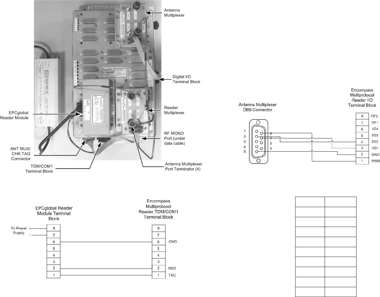
Installing the Antenna Multiplexer
To install the EPCglobal Reader Module on the Encompass
Reader
1. Install the antenna multiplexer assembly on the Encompass
reader housing using the four standoffs provided (Figure 1).
Secure the module to the reader housing using the Phillips
screws provided with the kit.
2. Connect the antenna multiplexer to the external digital
input/output (I/O) port on the Encompass reader (Figure 1
and Figure 3).
Figure 3. Antenna Multiplexer-to-Digital I/O Wiring Diagram
Table 1 lists the cable terminations for the DB9 connector-to- I/O
terminal block.
Figure 1. Encompass Multiprotocol Reader Showing
EPCglobal Reader Module and Reader and
Antenna Multiplexers Table 1. Antenna Multiplexer-to-Encompass Reader I/O Block
DB9 Pin I/O Pin
1 NC
6 1
2 4
7 3
3 NC
8 NC
4 NC
9 NC
5 2
Figure 2. EPC Module-to-Encompass Reader Wiring Diagram
8 9