TransCore 05726 LOW POWER TRANSCEIVER MODULE User Manual Encompass IAG PnP Reader System User s Manual
TransCore LOW POWER TRANSCEIVER MODULE Encompass IAG PnP Reader System User s Manual
Users Manual
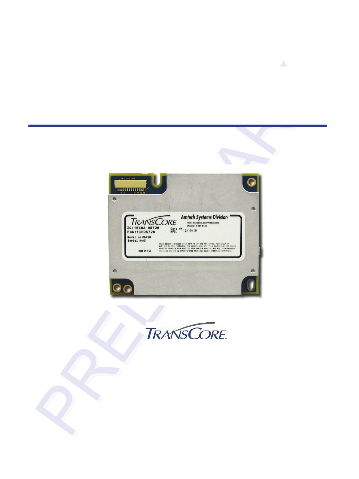
05726 IAG Read-Only Radio Module
Developer’s Guide
TransCore, Inc.
8600 Jefferson Street NE
Albuquerque, New Mexico 87113
December 2010
P/N 412114

©2010 TC License, Ltd. All rights reserved. TRANSCORE and ENCOMPASS are registered
trademarks of TC License. All other trademarks listed are the property of their respective owners.
Contents are subject to change. Printed in the U.S.A.
For further information, contact:
TransCore
3410 Midcourt Road, Suite 102
Carrollton, Texas 75006 USA
Phone: (214) 461-4031
Fax: (214) 461-6478
Technical Support
Web: transcore.com/rfidsupport
NO UNAUTHORIZED MODIFICATIONS
CAUTION: TRANSCORE IS NOT RESPONSIBLE FOR ANY RADIO OR TV
INTERFERENCE CAUSED BY UNAUTHORIZED MODIFICATIONS TO THIS EQUIPMENT.
SUCH MODIFICATIONS COULD VOID THE USER’S AUTHORITY TO OPERATE THE
EQUIPMENT.

Contents
Hardware Overview ........................................................................................................ 1
RF Connector .............................................................................................................. 1
Digital Connector ........................................................................................................... 2
Firmware Overview ........................................................................................................ 2
Regional Support ........................................................................................................... 3
Frequency ....................................................................................................................... 3
Host-to-Reader Communication ................................................................................... 4
Reader -to-Host Communication .................................................................................. 5
CCITT CRC-16 Calculation ......................................................................................... 6
Antenna Connector ........................................................................................................ 8
Communications Connector ......................................................................................... 8
Connectors ..................................................................................................................... 9
List of Figures
Figure 1. Host-to-Reader Communication Packets .......................................................................... 4
Figure 2. Host-to-Reader Communication Packets .......................................................................... 5
Figure 3. 05726 Radio Module Communications Interfaces ............................................................ 8
List of Tables
Table 1. Features of the 05726 Radio Module ................................................................................. 1
Table 2. Digital Connector Pin Assignments .................................................................................... 2
Table 3. Host-to-Reader Communication Descriptions .................................................................... 5
Table 4. Reader-to-Host Communication Descriptions .................................................................... 5
Table 5. Proposed Host-to-Reader Format of IAG Read (follows ThingMagic requirements) ......... 7
Table 6. Proposed Reader-to-Host Format of IAG Read Response ................................................ 7
iii

Introduction to the 05726 IAG
Read-Only Radio Module
The 05726 embedded IAG read-only module is a radio frequency identification
(RFID) radio that can be integrated into other systems to create RFID-enabled
products that support the E-ZPass® Interagency Group (IAG) protocol.
This document is written for developers and explains how to incorporate the 05726
TransCore Radio Module (hereafter called the 05726 radio module) into a third-party
host system.
Hardware Overview
The 05726 radio module is a single board module designed for more space-
constrained applications. The digital and analog electronics are located on the same
circuit board.
The 05726 radio module is designed to be incorporated into products requiring
capabilities in a small form factor. Table 1 shows the basic features of the radio
hardware.
Table 1. Features of the 05726 Radio Module
Specification Value
Input Power Requirements +5V DC
Communication Interfaces High-speed serial interface
Protocols supported IAG read-only
Dimensions (L x D x H) 3.1 x 2.5 x 0.3 in. (78 x 63 x 8 mm)
RF Connector
The 05726 radio module supports one MMCX connector for a single monostatic
antenna.
1
05726 IAG Read-Only Radio Module Developer’s Guide
Digital Connector
The digital connector provides power and serial communications signals. The
connector is a 14-pin digital connector. Table 2 lists the pin-outs and descriptions.
Table 2. Digital Connector Pin Assignments
Pin No. Description
1 GND
2 GND
3 GND
4 +5V
5 +5V
6 NO CONNECTION
7 NO CONNECTION
8 NO CONNECTION
9 NO CONNECTION
10 NO CONNECTION
11 RS-232 RX TTL from host
12 RS-232 RX TTL to host
13 NO CONNECTION
14 NO CONNECTION
Firmware Overview
The software for the 05726 radio module is loaded at the factory and cannot be
updated in the field. If the software requires updating, the radio module has to be
returned to the factory.
2
05726 IAG Read-Only Radio Module Developer’s Guide
Functionality of the Embedded Module
Regional Support
This radio module has been designed to comply with the following regulatory
requirements:
North America Region FCC 47 CFG Chapter 1, Part 15
Industrie Canada RSS-210
Frequency
The 05726 radio module has been designed to operate at a fixed frequency of 915.00
MHz.
3
05726 IAG Read-Only Radio Module Developer’s Guide
Overview of the Communication
Protocol
The serial communication between a host and the reader is based on a synchronized
command-response/master-slave mechanism. Whenever the host sends a message to
the reader, it cannot send another message until after it receives a response. The
reader never initiates a communication session, only the host initiates a
communication session.
This protocol allows for each command to have its own timeout because some
commands require more time to execute than others. The host manages retries if
necessary, and the host tracks the state of the intended reader if it reissues a
command.
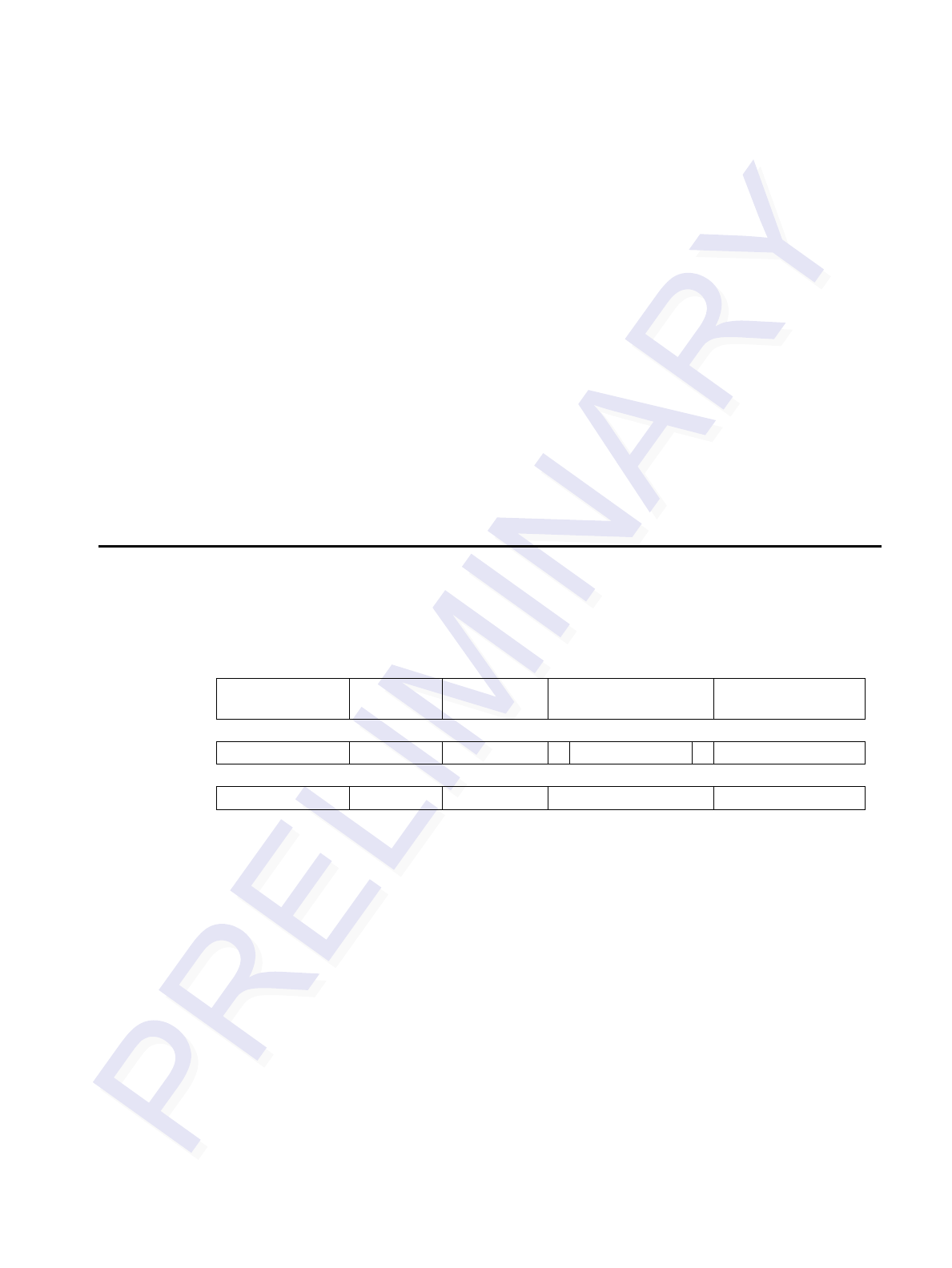
Host-to-Reader Communication
Host-to-reader communication is packetized according to Figure 1. The reader can
only accept one command at a time, and commands are executed serially, so the host
waits for a reader-to-host response before issuing another host-to-reader command
packet.
Header Data
Length Command Data CRC-16
Checksum
Hdr Len Cmd - - - - - CRC HI CRC LO
1 byte 1 byte 1 byte 0 to N bytes 2 bytes
Figure 1. Host-to-Reader Communication Packets
4
05726 IAG Read-Only Radio Module Developer’s Guide
The communication packet fields are summarized in Table 3.
Table 3. Host-to-Reader Communications
Field Length Description
Header (Hdr) 1 byte Defines the start of the packet. Equal to 0xFF
1Data Length (Len) 1 byte Defines the length, N, of the data field contained in the
packet.
Command 1 byte Specifies the command that the reader is to execute.
Data N bytes (0 to 250) Defines the binary data required by the reader for use with
a command. This could, for example, represent the
transponder data to be written. The length, N, can vary
between 0 and 250 bytes.
CRC-16 Checksum
(CRC HI, CRC LO) 2 bytes CRC-16 checksum (high order byte first). CRC polynomial
is CCITT CRC-16, with a preload of 0xFFFF. This does
not fully specify the operation of the CRC. See the CCITT
CRC-16 Calculation section for more details.
Reader -to-Host Communication
Figure 2 defines the format of the generic response packet that is sent from the reader
to the host. The response packet is different in format from the request packet.
Header Data
Length Command Status Word Data CRC-16
Checksum
Hdr Len Cmd Status Word - - - - - CRC HI CRC LO
1 byte 1 byte 1 byte 2 bytes 0 to M bytes 2 bytes
Figure 2. Reader-to-Host Communication Packets
The response packet fields are summarized in Table 4.
Table 4. Reader-to-Host Communications
Field Length Description
Header (Hdr) 1 byte Defines the start of the packet. Equal to 0xFF
1Data Length (Len) 1 byte Defines the length, M, of the data field contained in the
packet. Length can be 0 to 248 bytes.
2Command 1 byte Specifies the command that the reader is to execute.
3Status Word 2 bytes Specifies the status of the last command.
Successful = 0x0000, else it contains a fault code.
1 Minimum packet length is 5 bytes and the maximum packet length is 255 bytes.
2 Each host command receives a response from the reader. In the response packet, the Header, Data Length,
Command, Data, and Checksum are functionally similar to the command packet.
3 The only difference is the addition of the Status Word field. The Status Word has two types of values: a Status
Word value of 0 (zero) means the command received was successful; any other value represents a fault.
5
05726 IAG Read-Only Radio Module Developer’s Guide
Field Length Description
Data M bytes (0 to 248) Defines the binary data required by the reader for use
with a command. This could, for example, represent
data read from a transponder. Data length, M, can be a
minimum of 0 bytes and a maximum of 248 bytes.
CRC-16 Checksum
(CRC HI, CRC LO) 2 bytes CRC-16 checksum (high order byte first). CRC
polynomial is CCITT CRC-16, with a preload of 0xFFFF.
This does not fully specify the operation of the CRC.
See the CCITT CRC-16 Calculation section for more
details.
CCITT CRC-16 Calculation
The same CRC calculation is performed on all serial communications between the
host and the reader. The CRC is calculated on the Data Length, Command, Status
Word, and Data bytes. The Header (SOH, 0xFF) is not included in the CRC.
6
05726 IAG Read-Only Radio Module Developer’s Guide
Command Set
The 05726 radio module uses only one command:
• 0xFF – IAG read-only command.
The Read command from the host causes the microcontroller to generate a Tx_enable signal,
used by a 915-MHz oscillator and output RF switch, to generate a 20-microsecond trigger
pulse. Instead of a timeout period specified in a command, the microcontroller generates up
to 10 trigger pulses separated by 100 milliseconds. The microcontroller stops when a tag is
seen or when 10 pulses have been generated.
Following the command formatted used by ThingMagic and TransCore’s Encompass® 1d
host programs, the commands necessary for the 05726 radio module prototype are listed in
the following tables.
Table 5. Proposed Host-to-Reader Format of IAG Read
(follows ThingMagic requirements)
Header Data Length Command Data CRC-16
FFH 02H 21H XXXXH XXH
Where
Data Length Number of bytes in the Data field
Data payload Set Data 0000H
CRC CRC-16 Checksum. See Reader-to-Host
Communications for details.
Table 6. Reader-to-Host Format of IAG Read Response
Header Data Length Command Status Word Data CRC-16
FFH 20H 21H 0X00H (256 bits) XXH
Where
Data Length Number of bytes in the Data field
Status Word 0000H if tag CRC check succeeds
0400H if no tag found
0500H if tag CRC check fails
Data Payload Current firmware returns all zeros (0)
CRC CRC-16 Checksum. See Host-to-Reader Communications for details.
7
05726 IAG Read-Only Radio Module Developer’s Guide
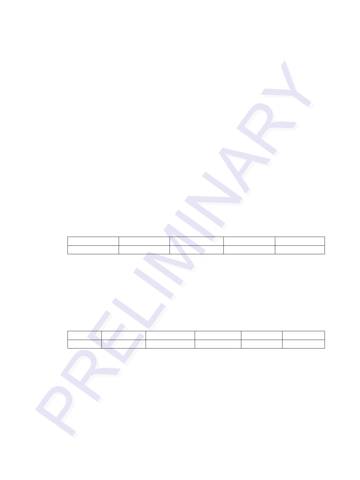
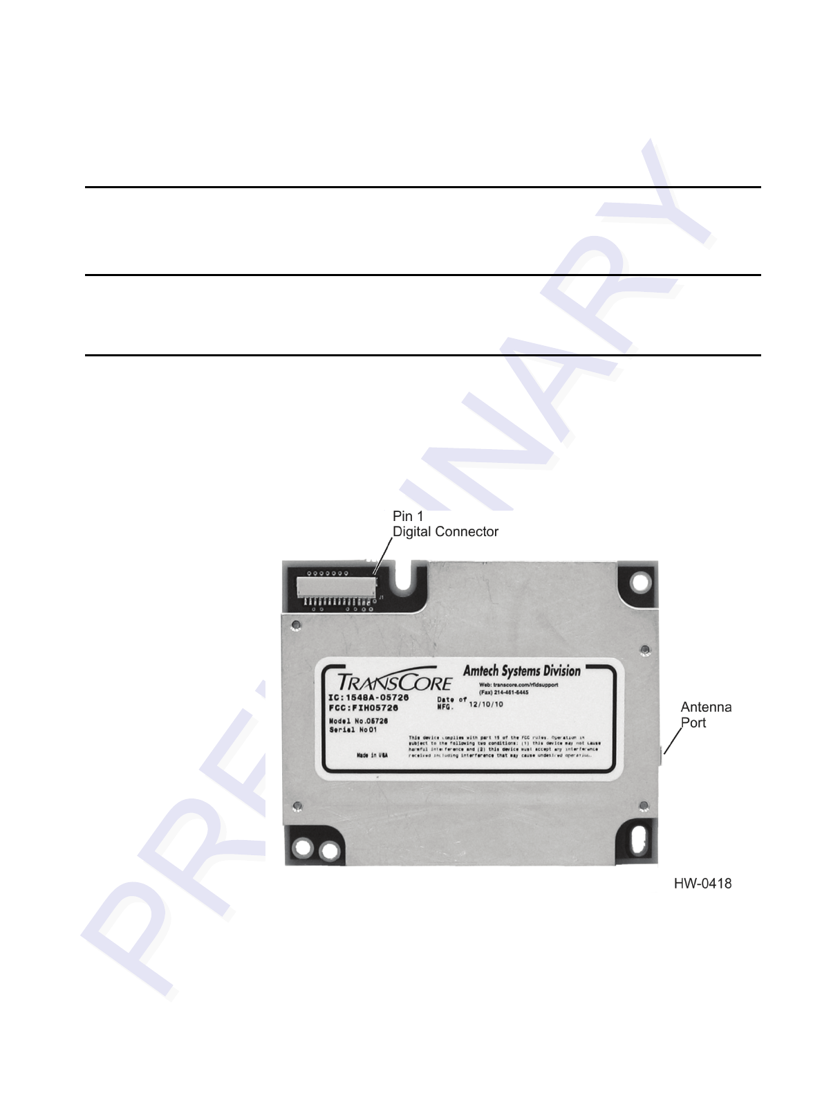
Hardware Details
This section details the physical components of the 05726 radio module including the pin 1
location for the serial connector.
Antenna Connector
The 05726 radio module has one MMCX connector for interfacing to an antenna.
Communications Connector
The communications interface on the module provides power, serial communications
signals, and access to the general purpose inputs and outputs.
The 05726 radio module has a 14-pin connector. For the interface pin-out, see the
05726 Radio Digital Connectors section for more detail.
Figure 3 shows the 05726 radio module communications interfaces.
Figure 3. 05726 Radio Module Communications Interfaces
8

05726 IAG Read-Only Radio Module Developer’s Guide
Connectors
The connector used for the communications interface on the 05626 radio module is as
follows:
• JST SM14B-SRSS-TB
The mating connectors are as follows:
• Connector Shell: JST SHR-14V-S-B
• Crimp Contacts: JST SSH-003T-PO.2-H
9

05726 IAG Read-Only Radio Module Developer’s Guide
10