TransCore 0596465PT90 Location Monitoring Services Transmitter User Manual 412066 012 E4 SG
TransCore Location Monitoring Services Transmitter 412066 012 E4 SG
UserManual.wiki
>
TransCore
>
0596465PT90 User Manual
User Manual
Navigation menu
Upload a User Manual
Namespaces
Wiki Guide
HTML
PDF
Info
Views
User Manual
Discussion / Help
Navigation


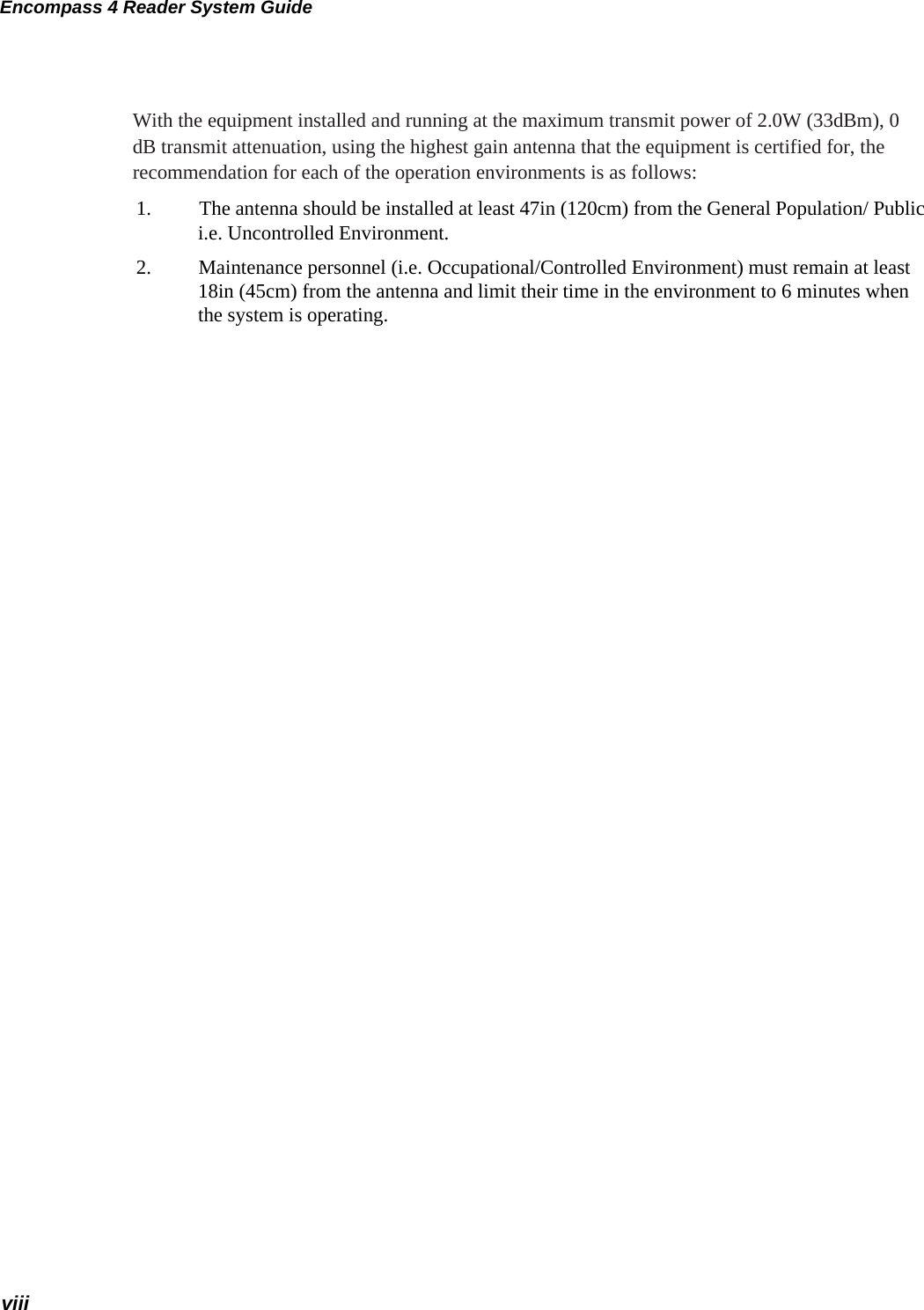


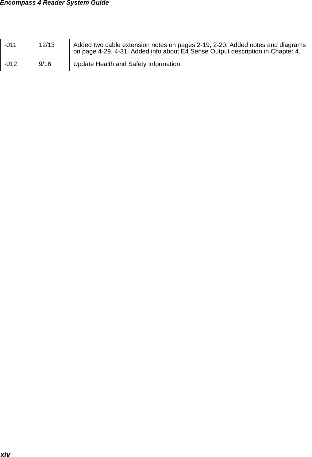
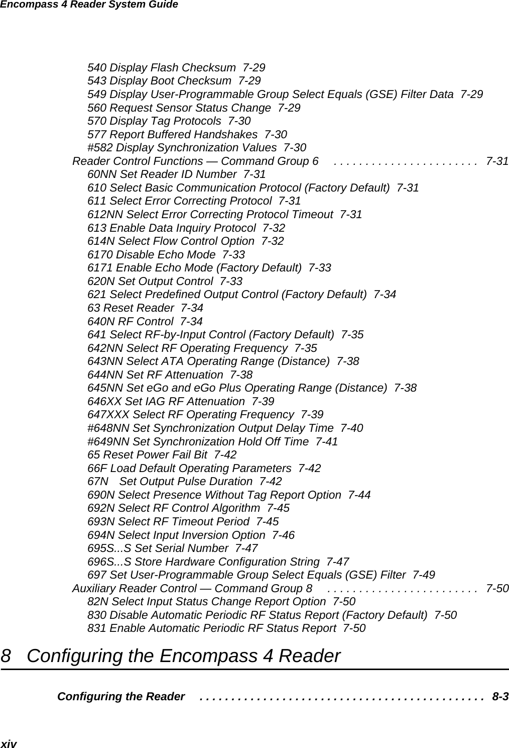


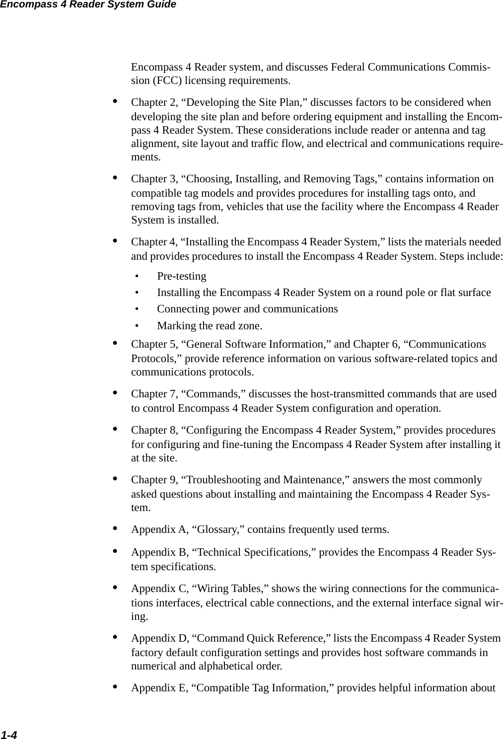


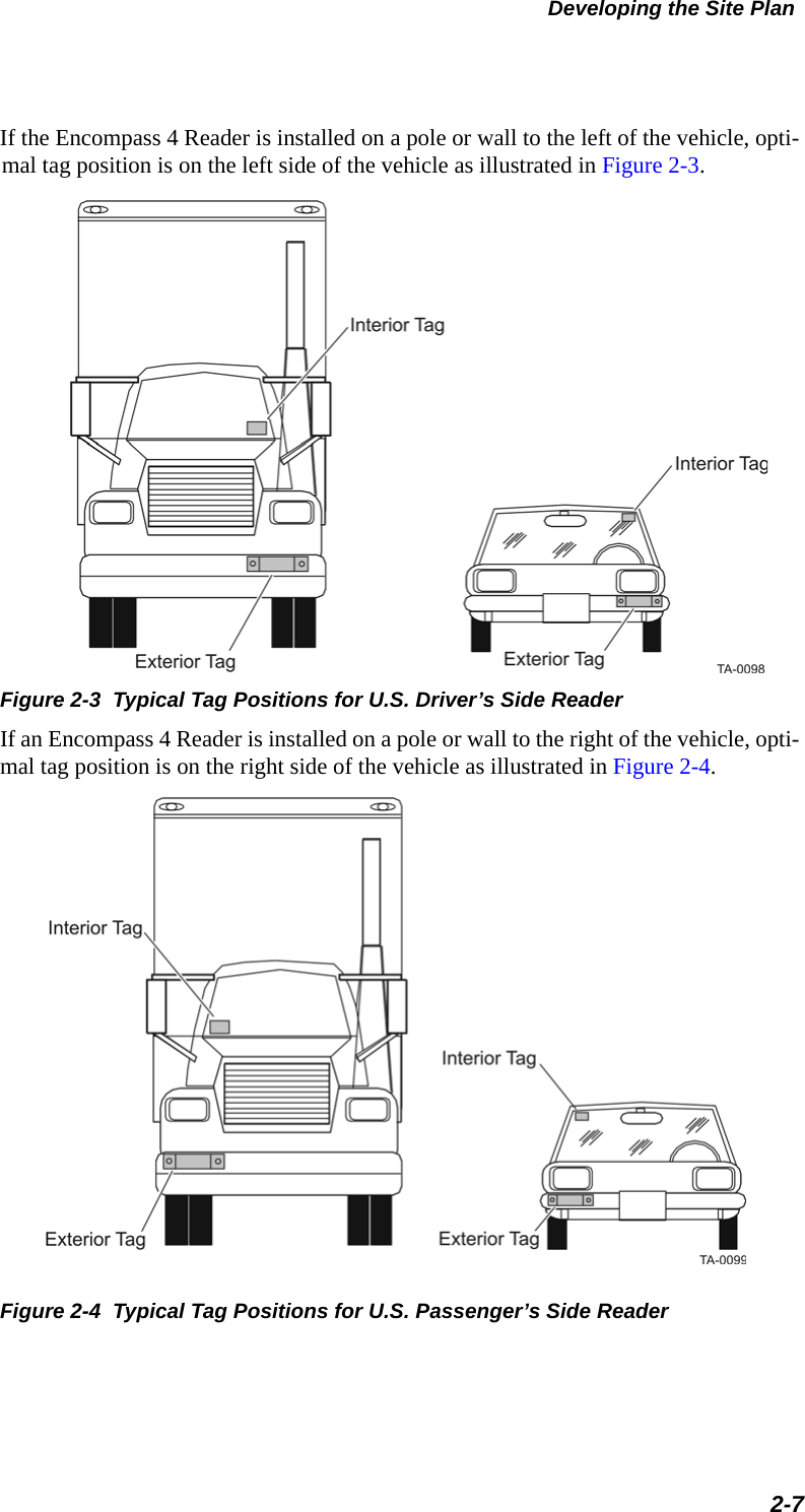
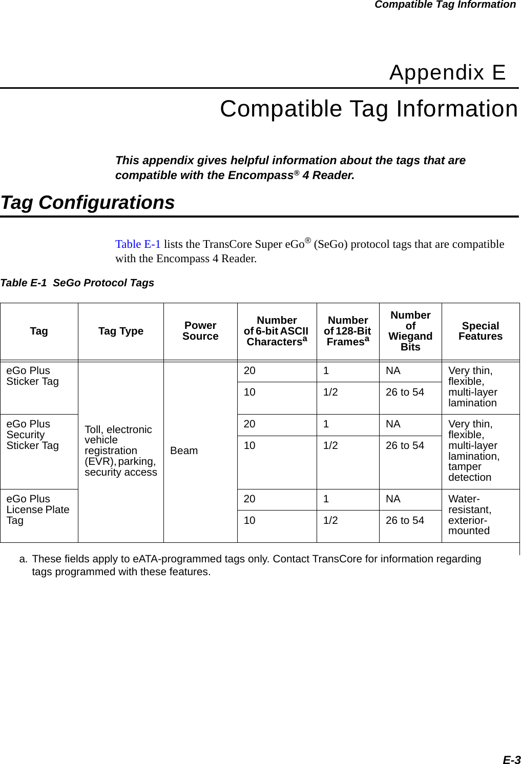
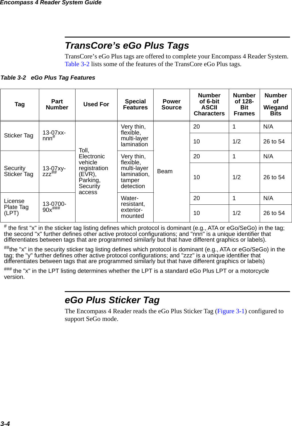
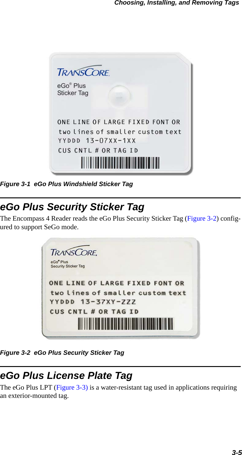
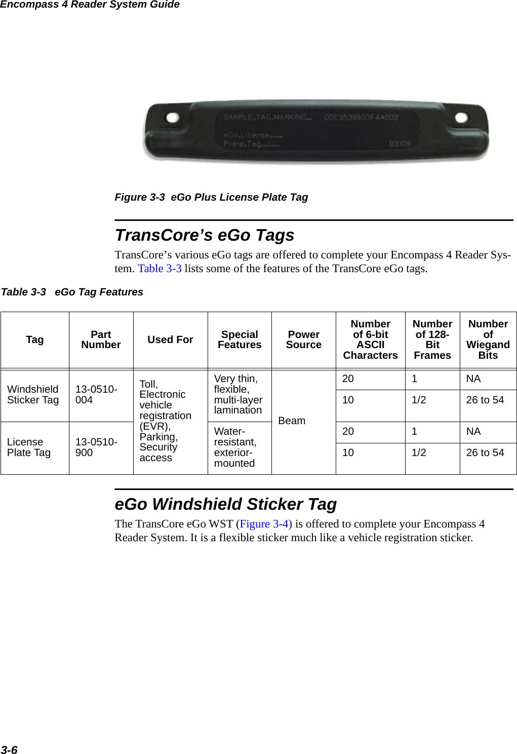
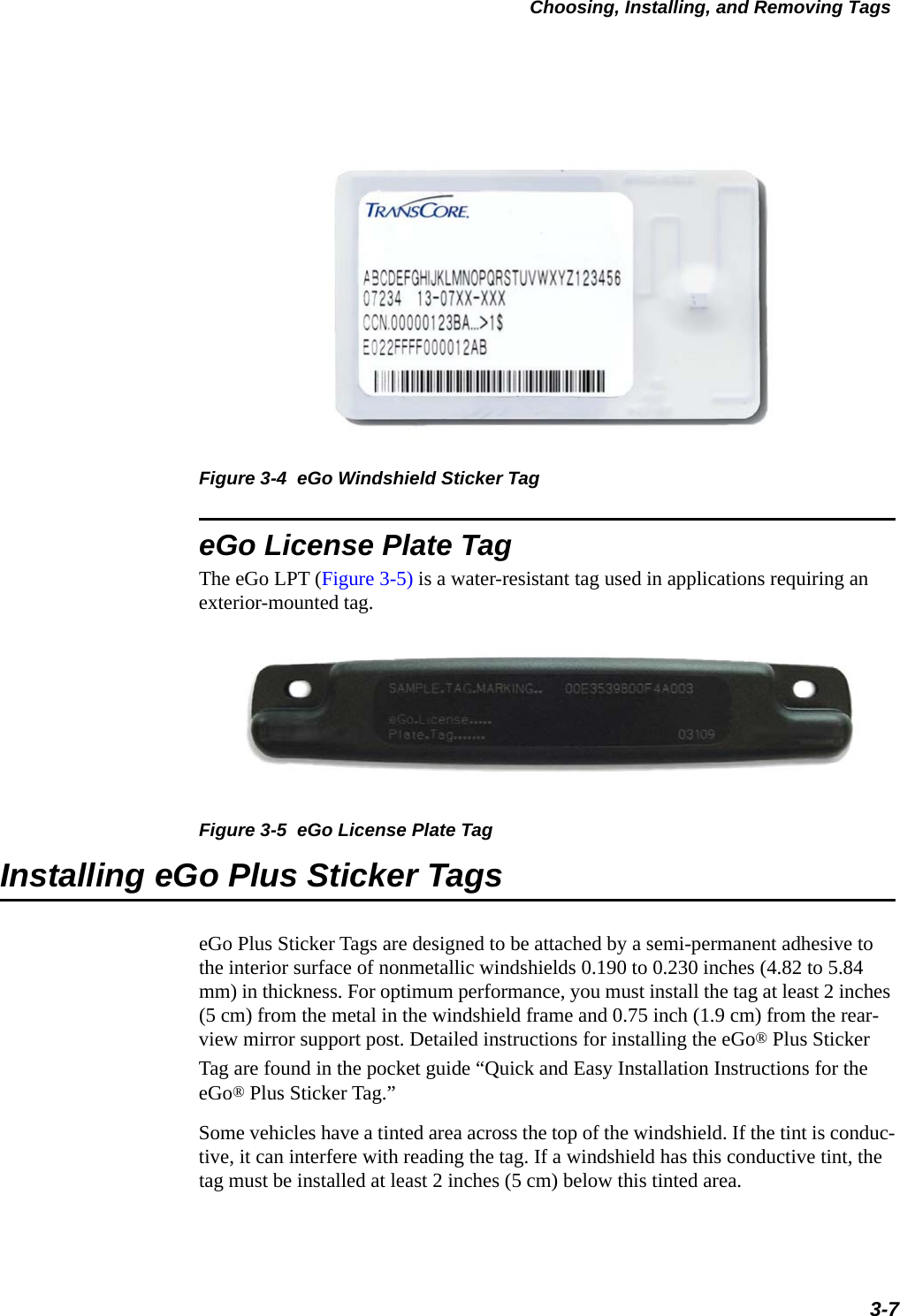
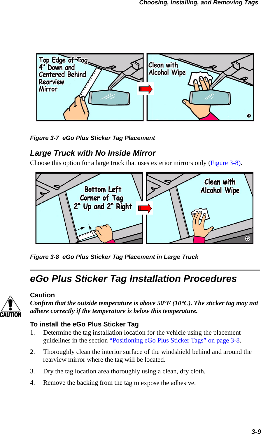
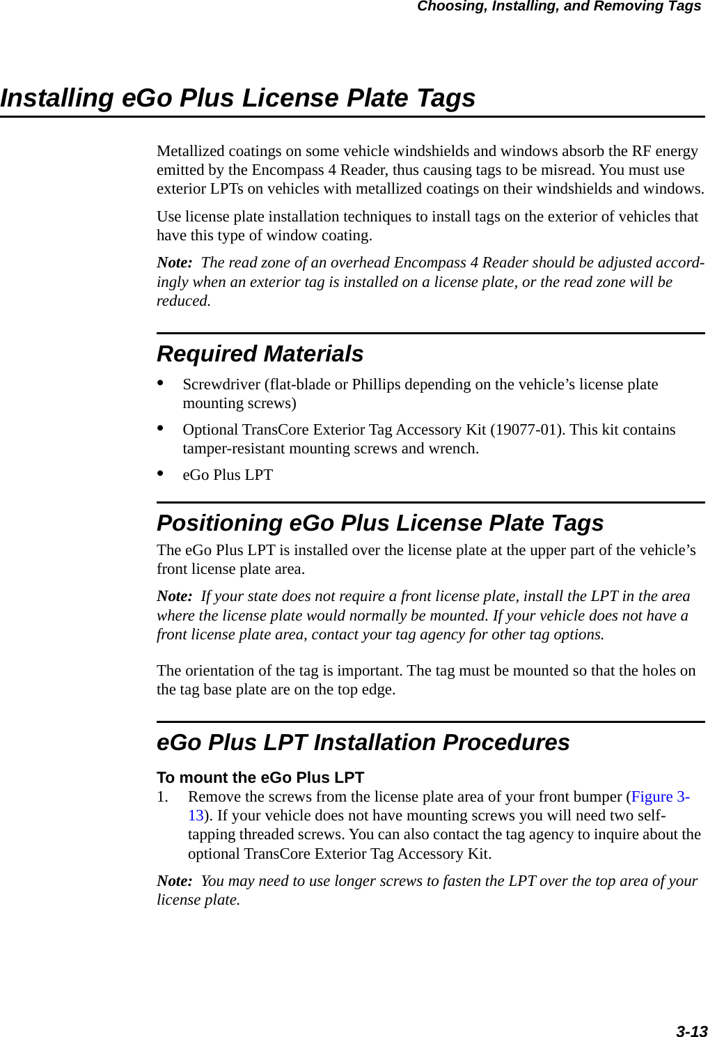
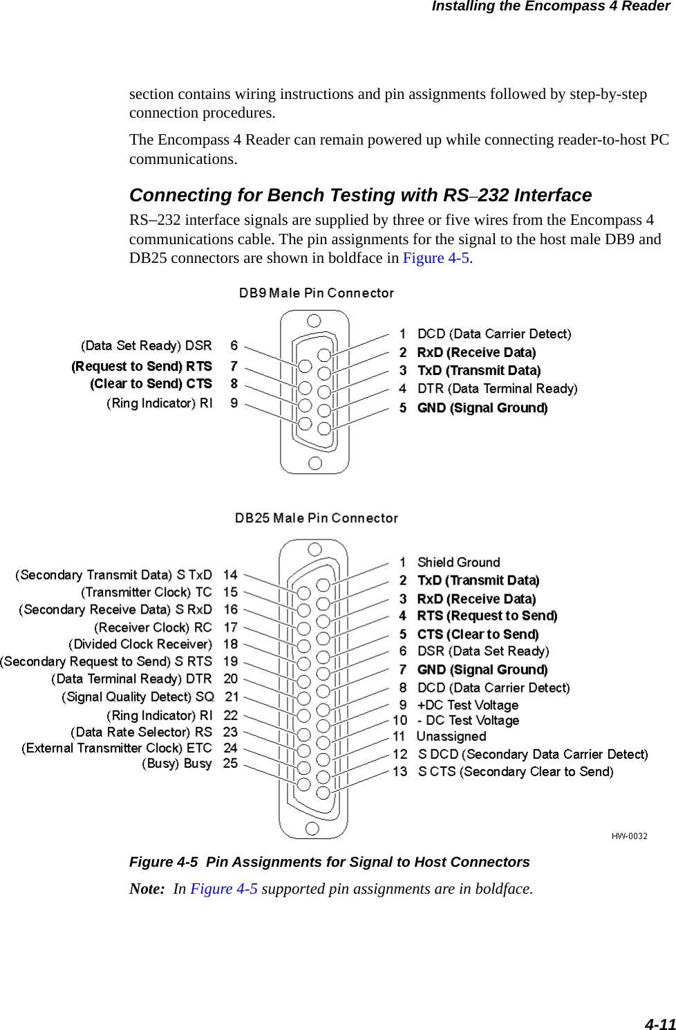
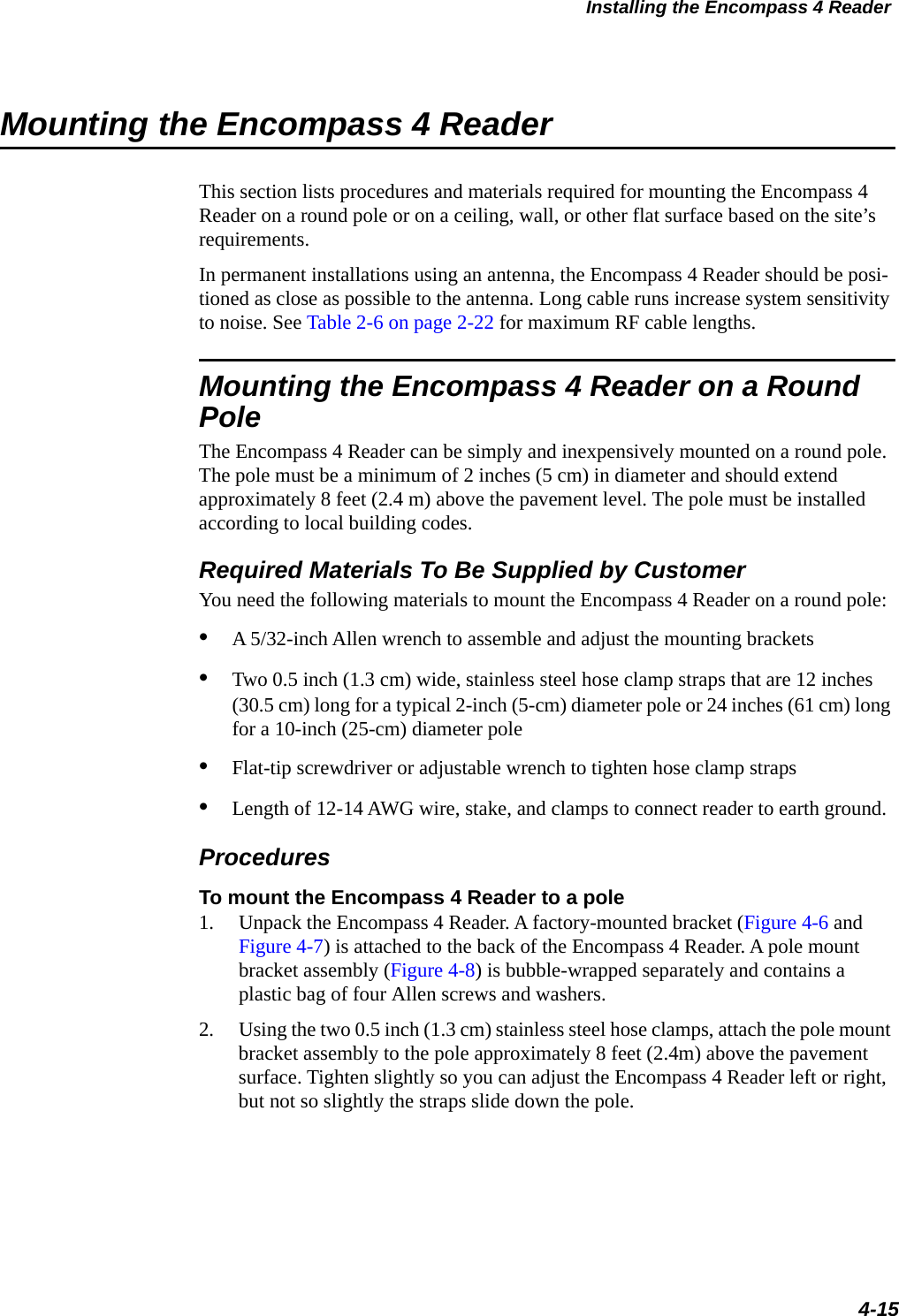
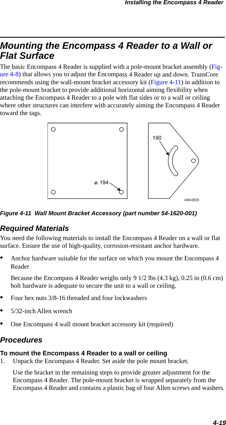
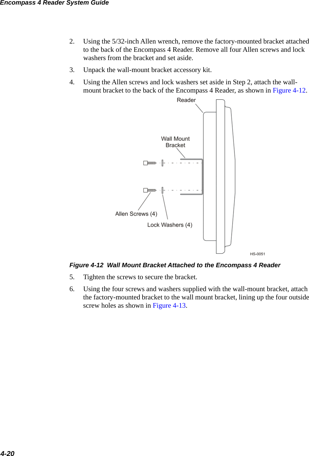
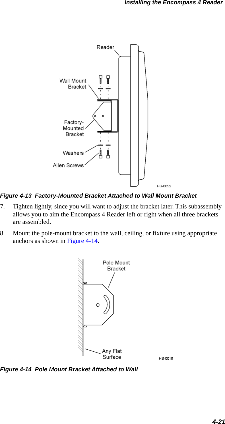
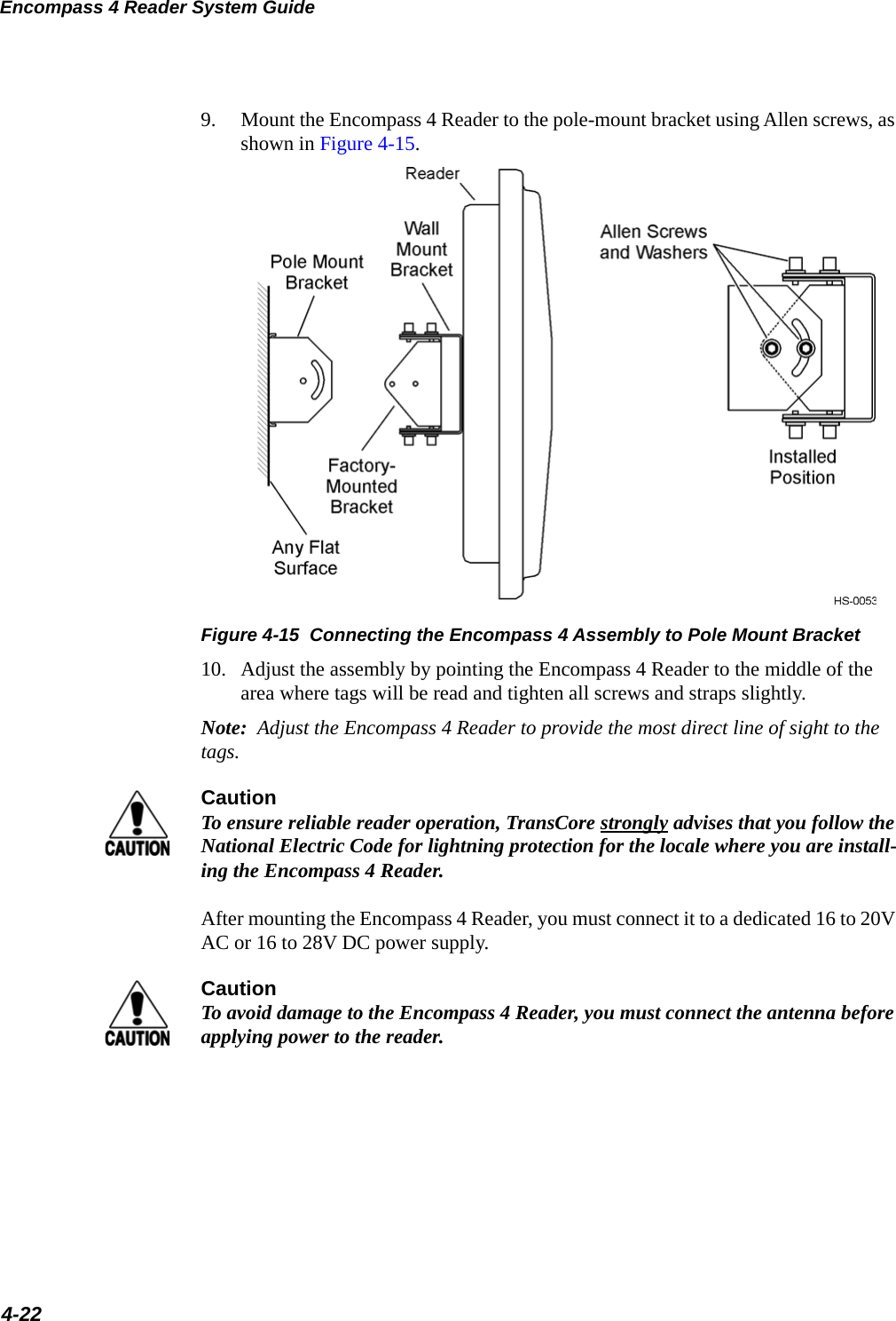
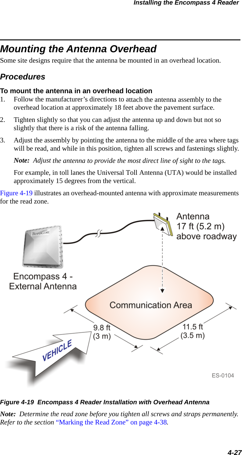
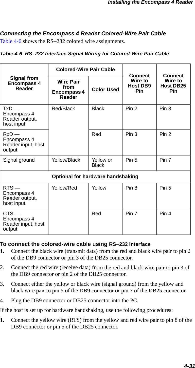
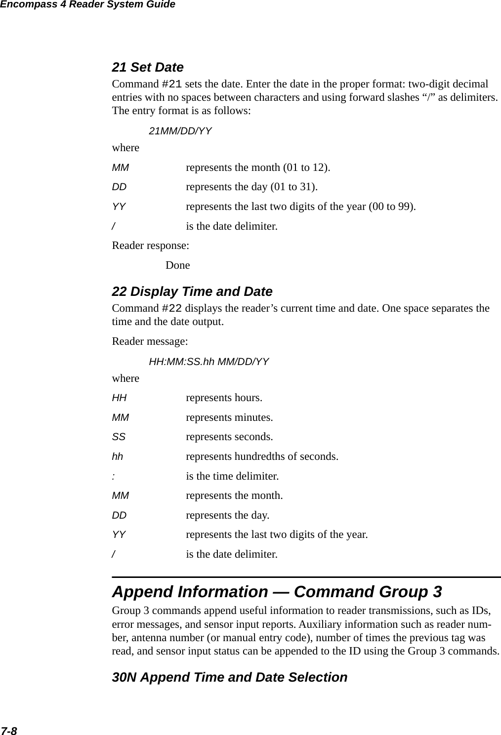
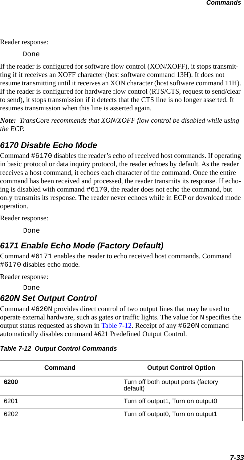
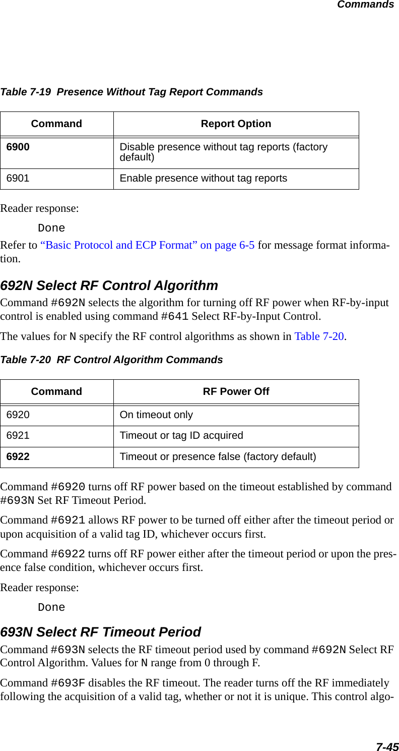
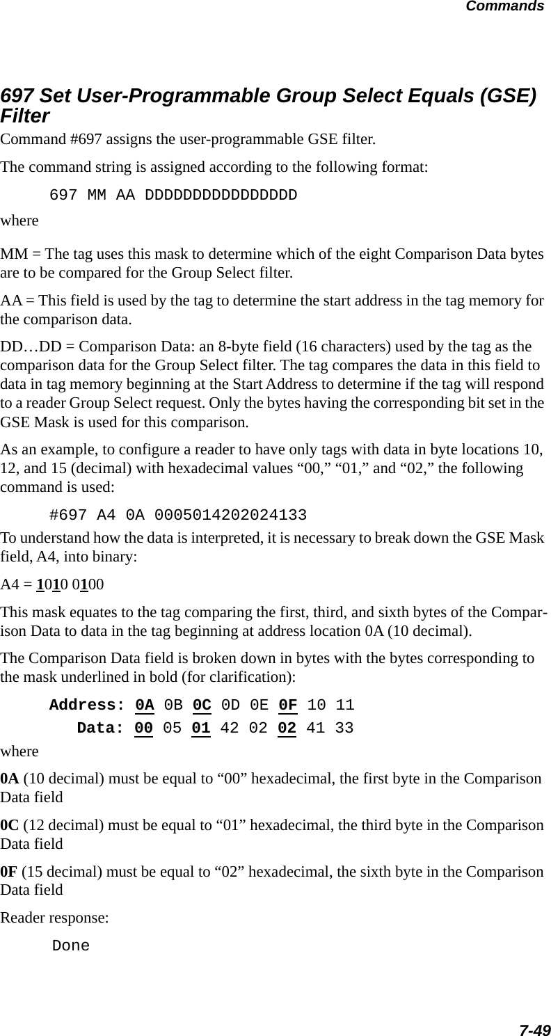
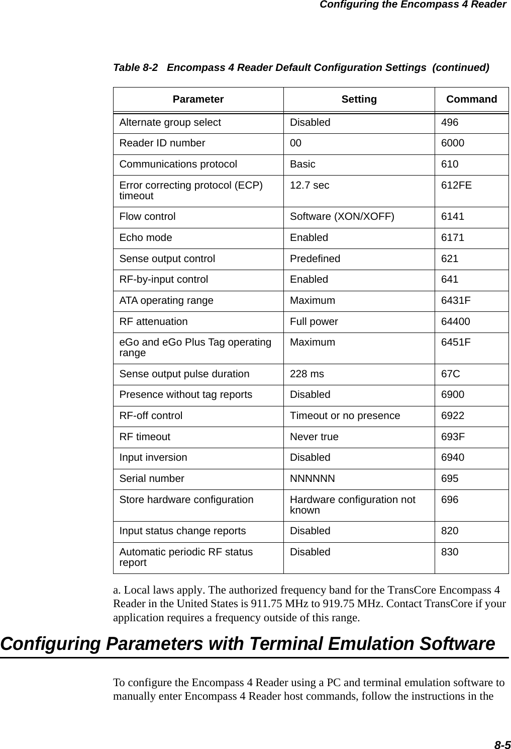
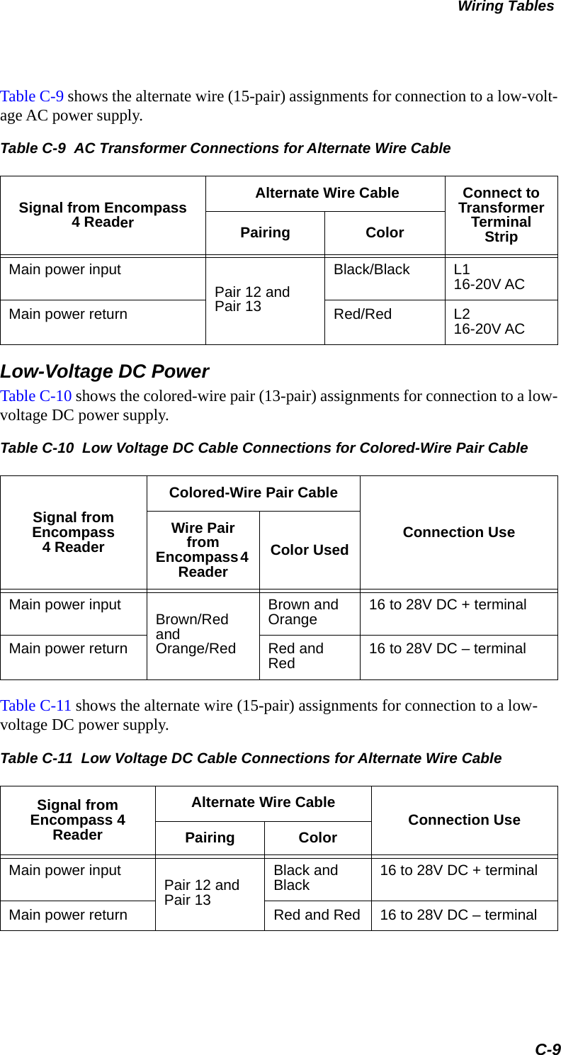
![Developing the Site Plan2-9•Relatively symmetrical reading range•Antenna profile not a major considerationAA3101 Yagi (with radome)Appropriate for installations with the following requirements and conditions:•902 to 928 MHz operation•Exposure to harsh environments•Relatively symmetrical reading range•Antenna profile not a major considerationAA3110 Parapanel Appropriate for installations with the following requirements and conditions:•902 to 928 MHz operation•Exposure to harsh environments•Broad radiation pattern in one dimension, narrow in the other•Low antenna profile•Horizontal polarizationAA3140 PCB Log PeriodicAppropriate for installations with the following requirements and conditions:•845 to 950 MHz operation•Exposure to harsh environments•Maximum coverage at close range (<20 ft [6.1 m])•Vertical or horizontal polarizationAA3152 Universal Toll AntennaAppropriate for installations with the following requirements and conditions:•902 to 928 MHz operation•Exposure to harsh environments•Broadcast pattern of similar size and shape in both horizontal and vertical planes](https://usermanual.wiki/TransCore/0596465PT90/User-Guide-3159238-Page-45.png)


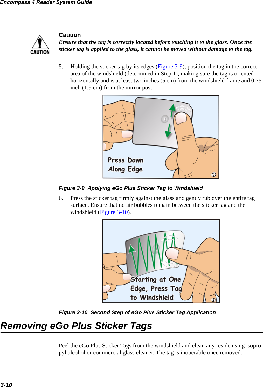
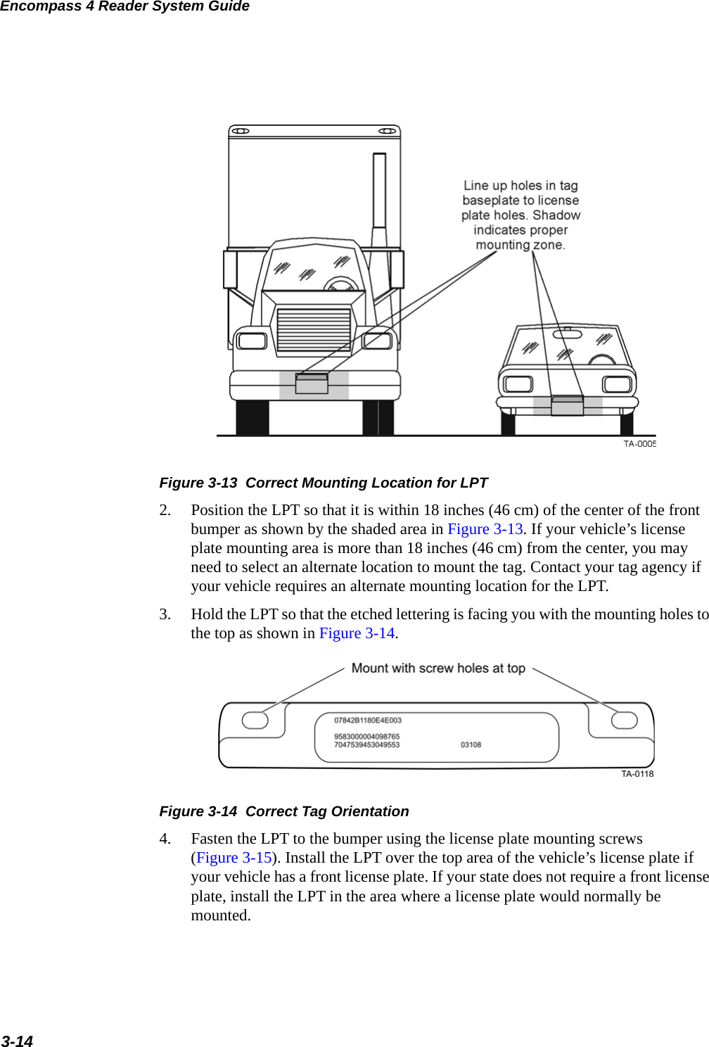


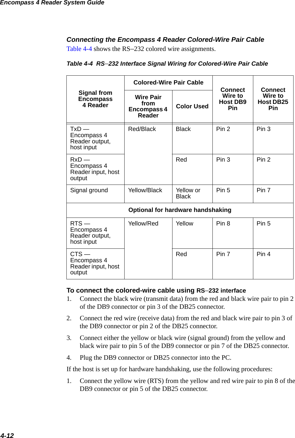
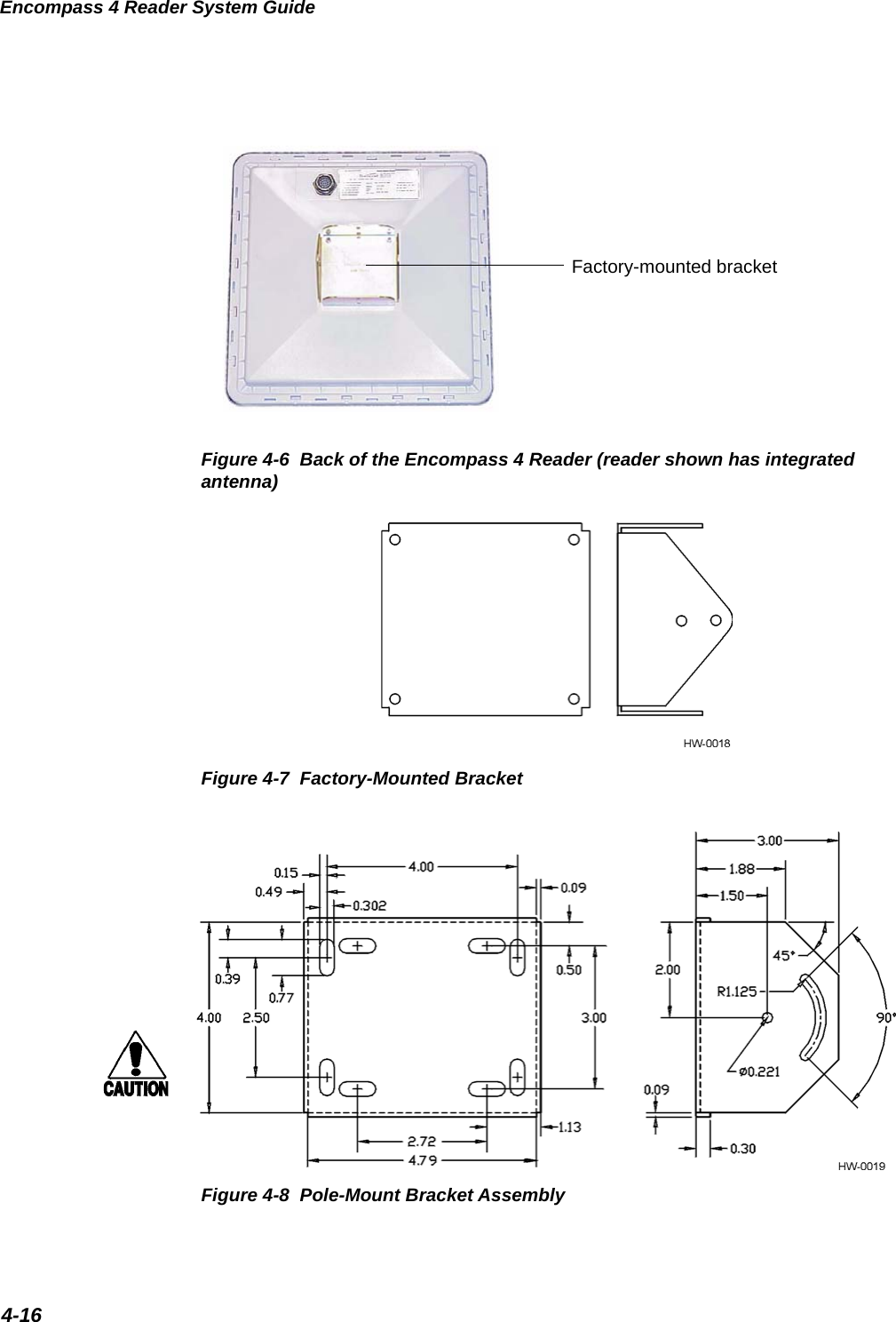
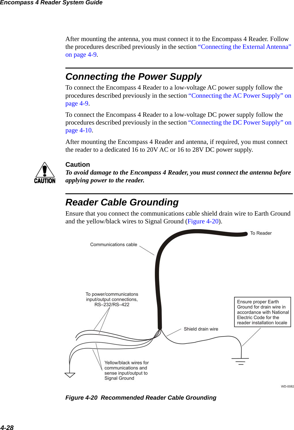
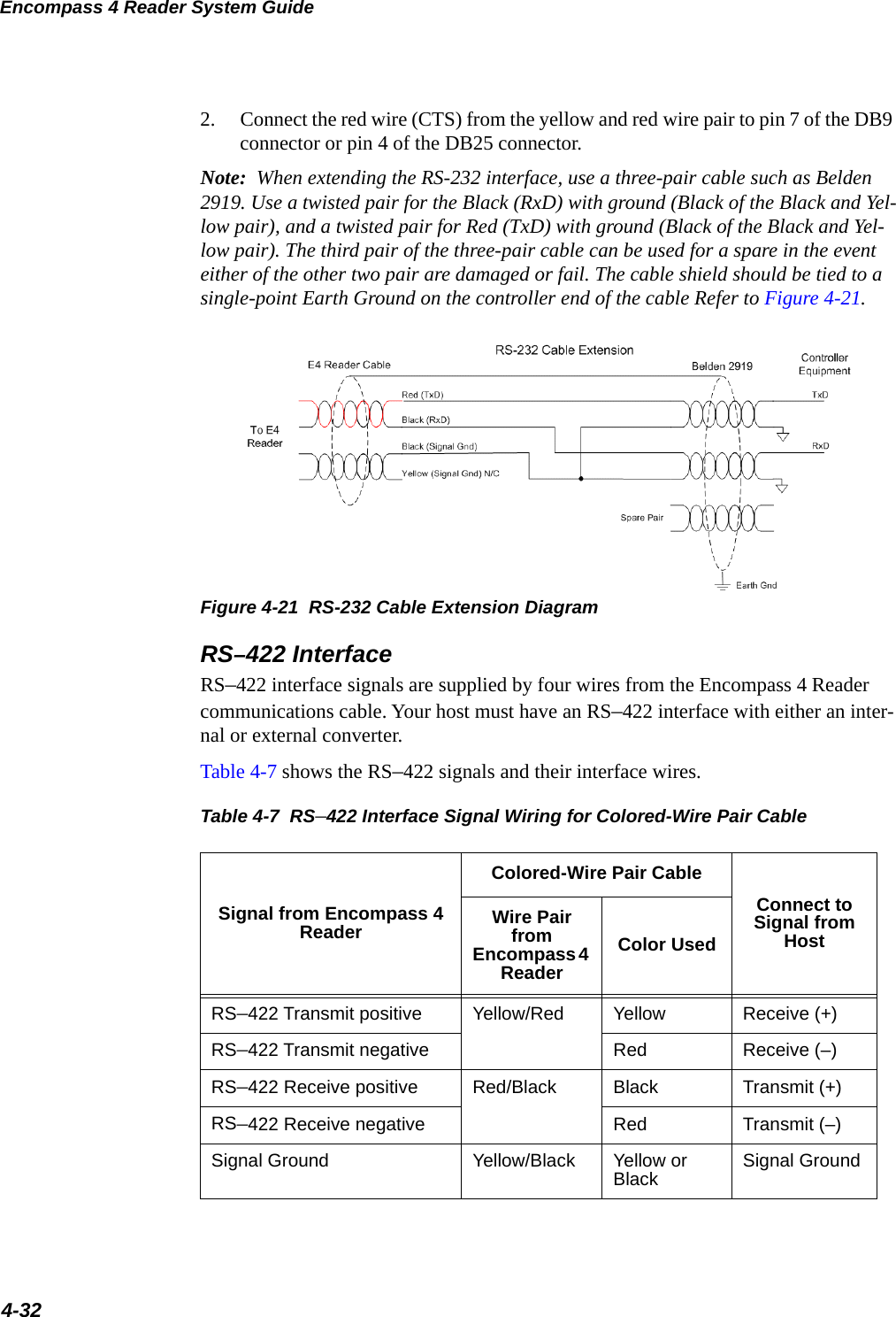


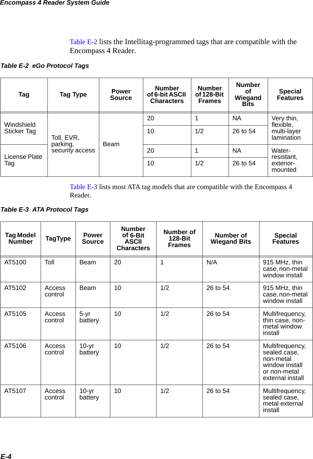
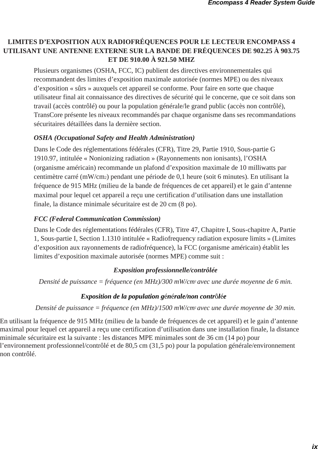
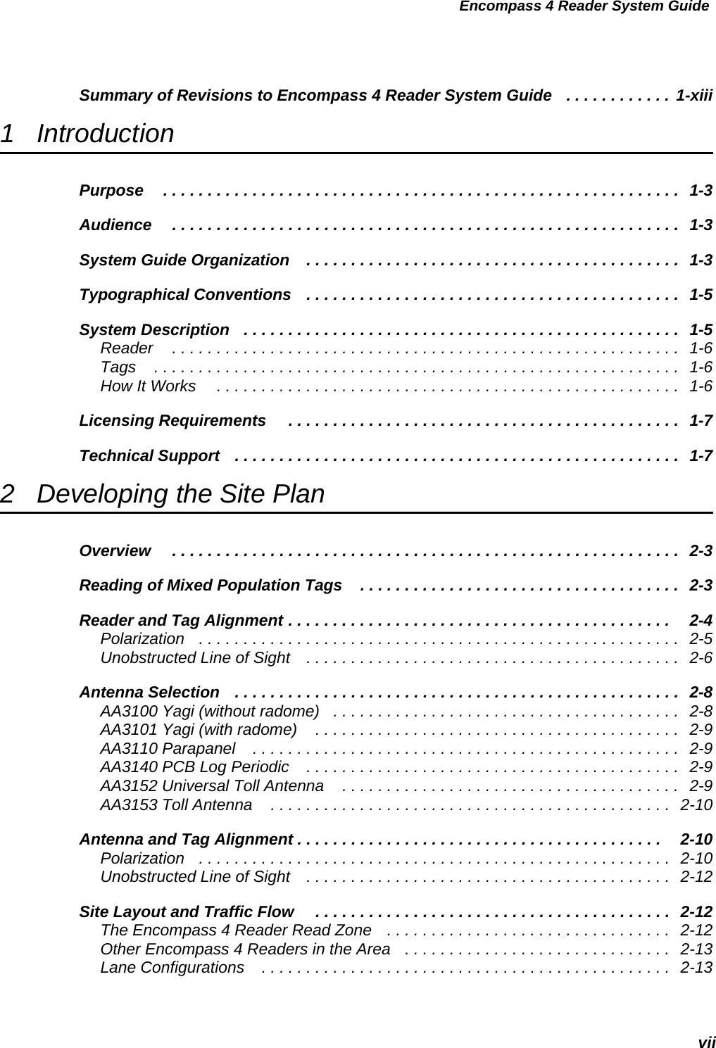
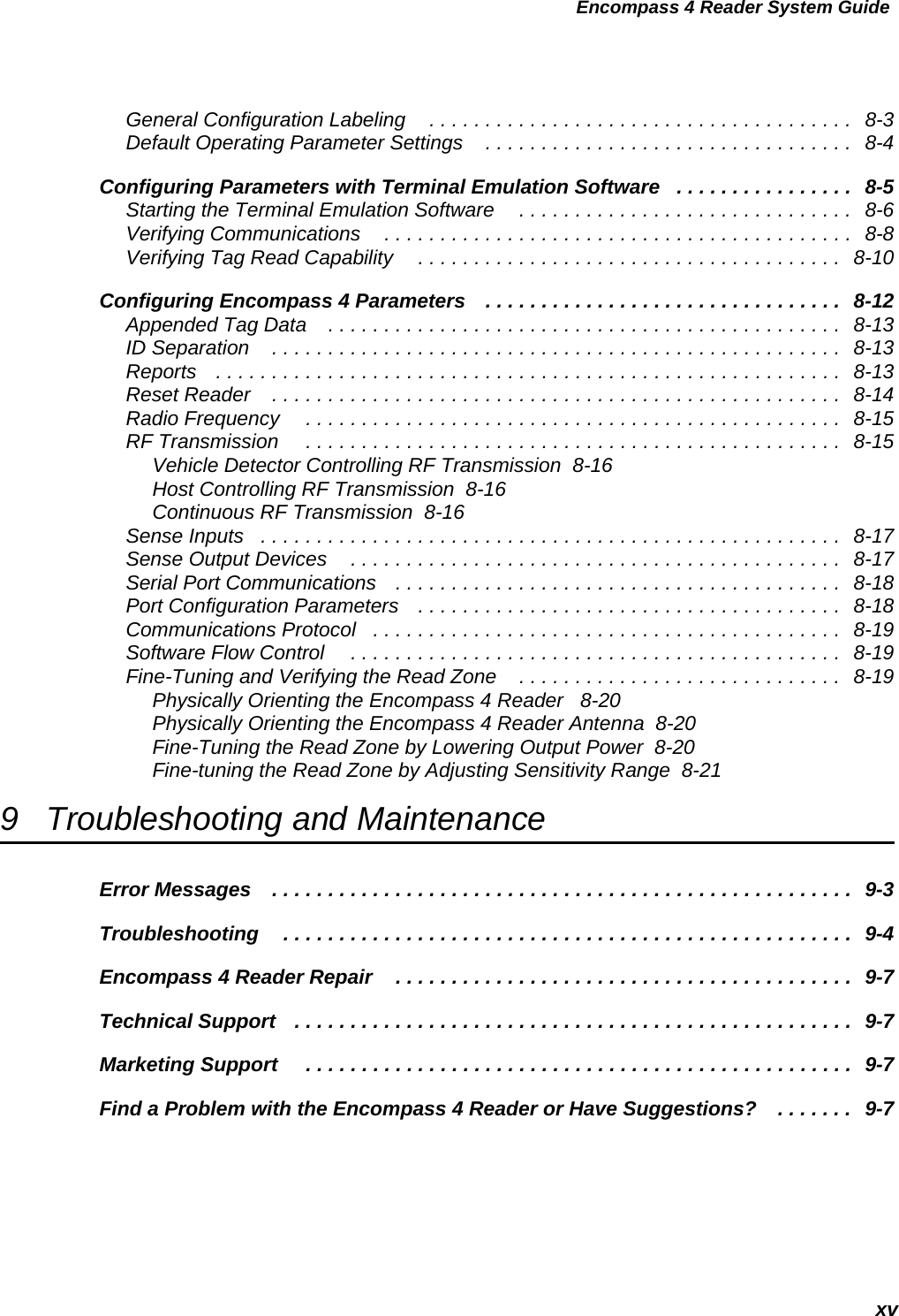
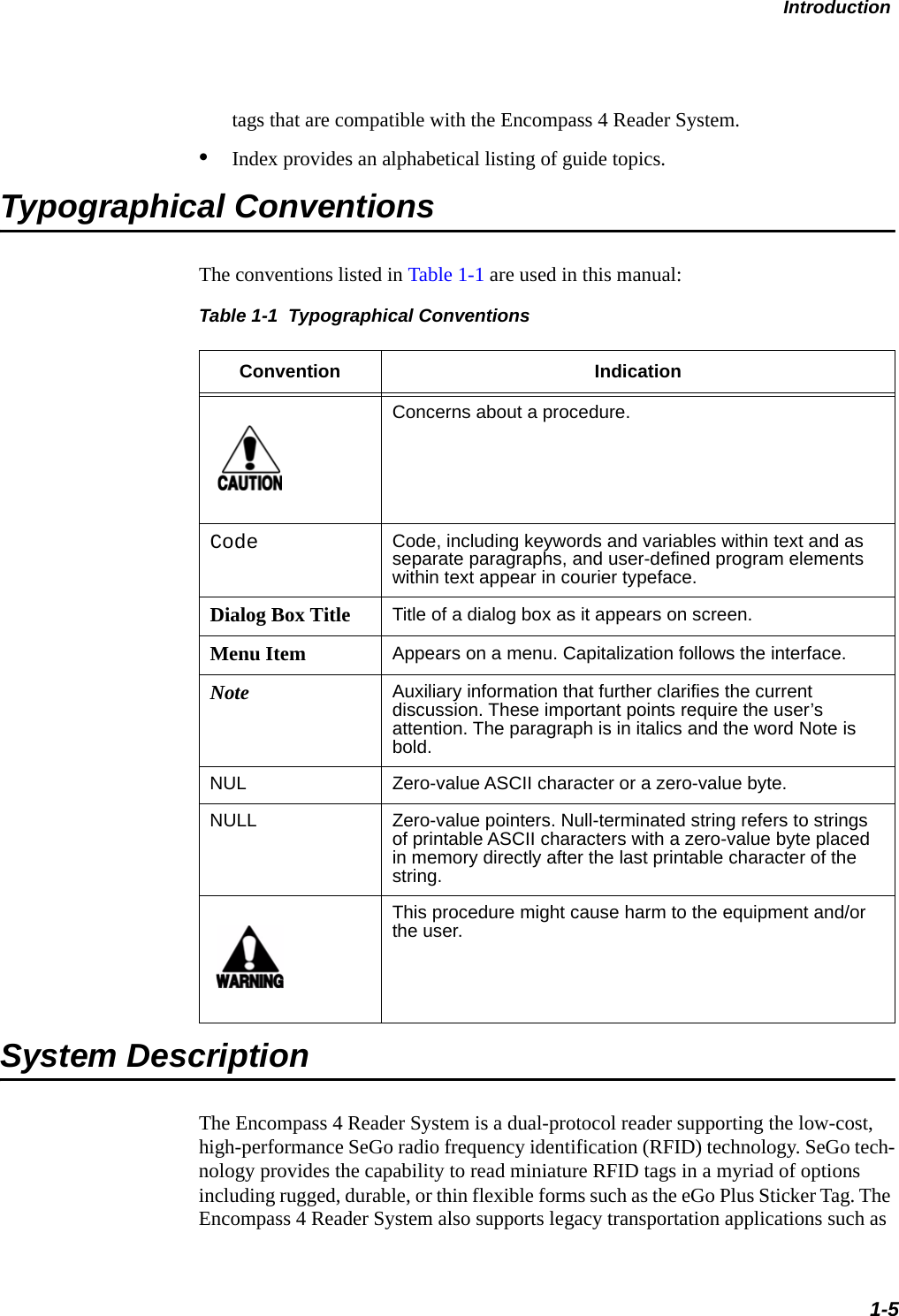
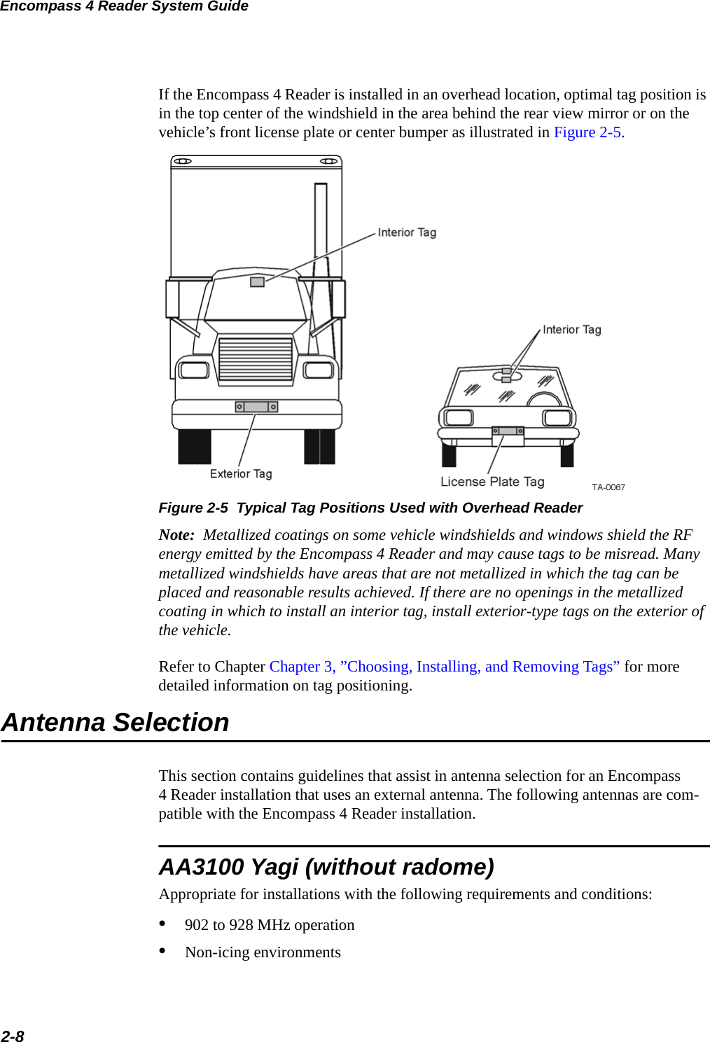
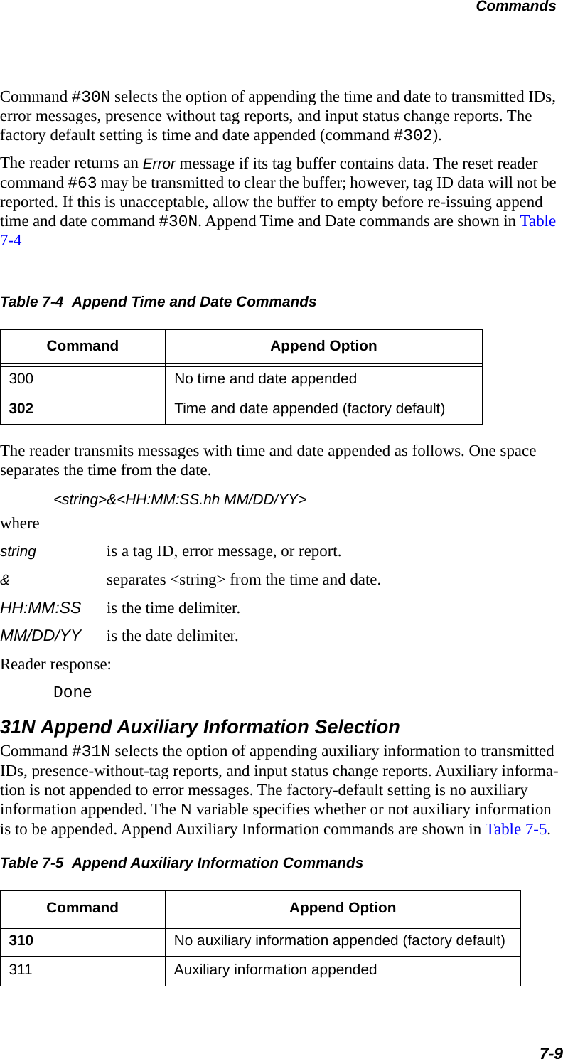
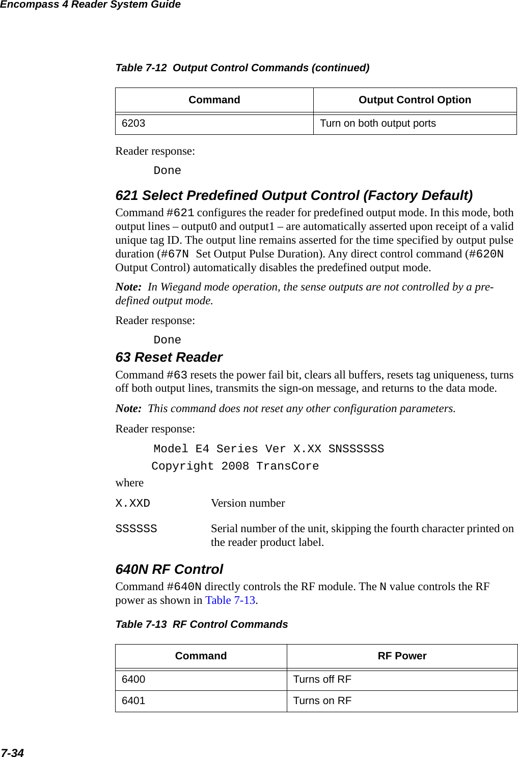
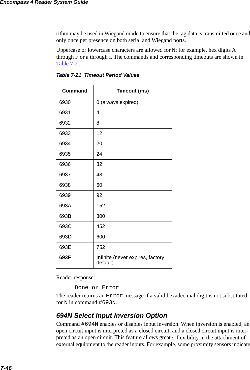
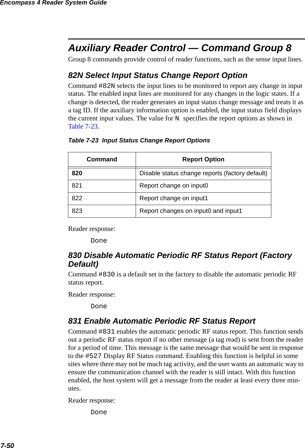
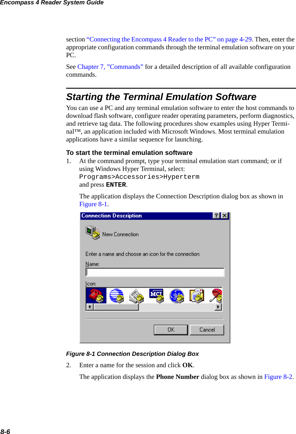
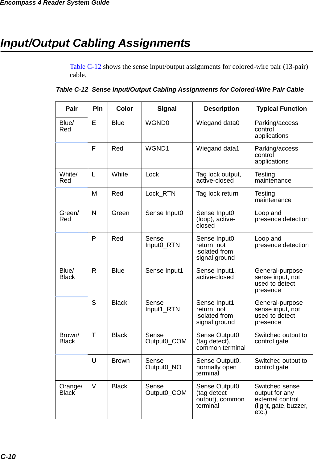
![Encompass 4 Reader System Guide5-6If TransCore releases a new version of the Encompass 4 Reader software or if the Encompass 4 Reader seems not to be working properly, you may need to download the software to the Encompass 4 Reader. Contact technical support or your TransCore Encompass 4 Reader sales representative.StartupUpon startup, Encompass 4 Reader’s transmit a sign-on message or a boot ROM fail-ure message.Sign-On MessageIf startup is successful, the sign-on message appears as follows: Model E4 Series [software version] SNYYYYYY[Copyright notice]where YYYYYY is the serial number assigned to the 4800 Reader unit being used.Serial number 000000 is the default setting and is not a valid number. If this number appears in the sign-on message, the serial number has never been stored into reader memory. The serial number must be assigned by factory-authorized personnel using command #695S...S Set Serial Number. Because only six digits are allowed in the software, when setting the serial number skip the fourth (middle) digit of the seven-digit number shown on the reader label.If the flash memory checksum does not indicate verification, the sign-on message appears as follows:Model [E4] Ver 0.00x[Copyright notice]Boot Failure MessageThe software performs a checksum function on itself. The function returns a specific value for the particular version of software. If the value returned is not correct, the boot ROM checksum assumes that locations have been corrupted and a failure condi-tion exists. If the boot ROM checksum is not correct, a boot failure message is trans-mitted. If the failure message does not transmit, a communications error has occurred or the boot failed to the extent that it cannot transmit the failure message.If the failure message version number equals 0.00 and no serial number exists, the flash memory checksum has failed, and the Encompass 4 Reader is operating out of boot ROM. In this case, the Encompass 4 Reader automatically enters download mode and waits for a new program to be loaded into the flash memory. Follow the instruc-tions in “Program Download” on page 5-5 to download a new program.](https://usermanual.wiki/TransCore/0596465PT90/User-Guide-3159238-Page-134.png)


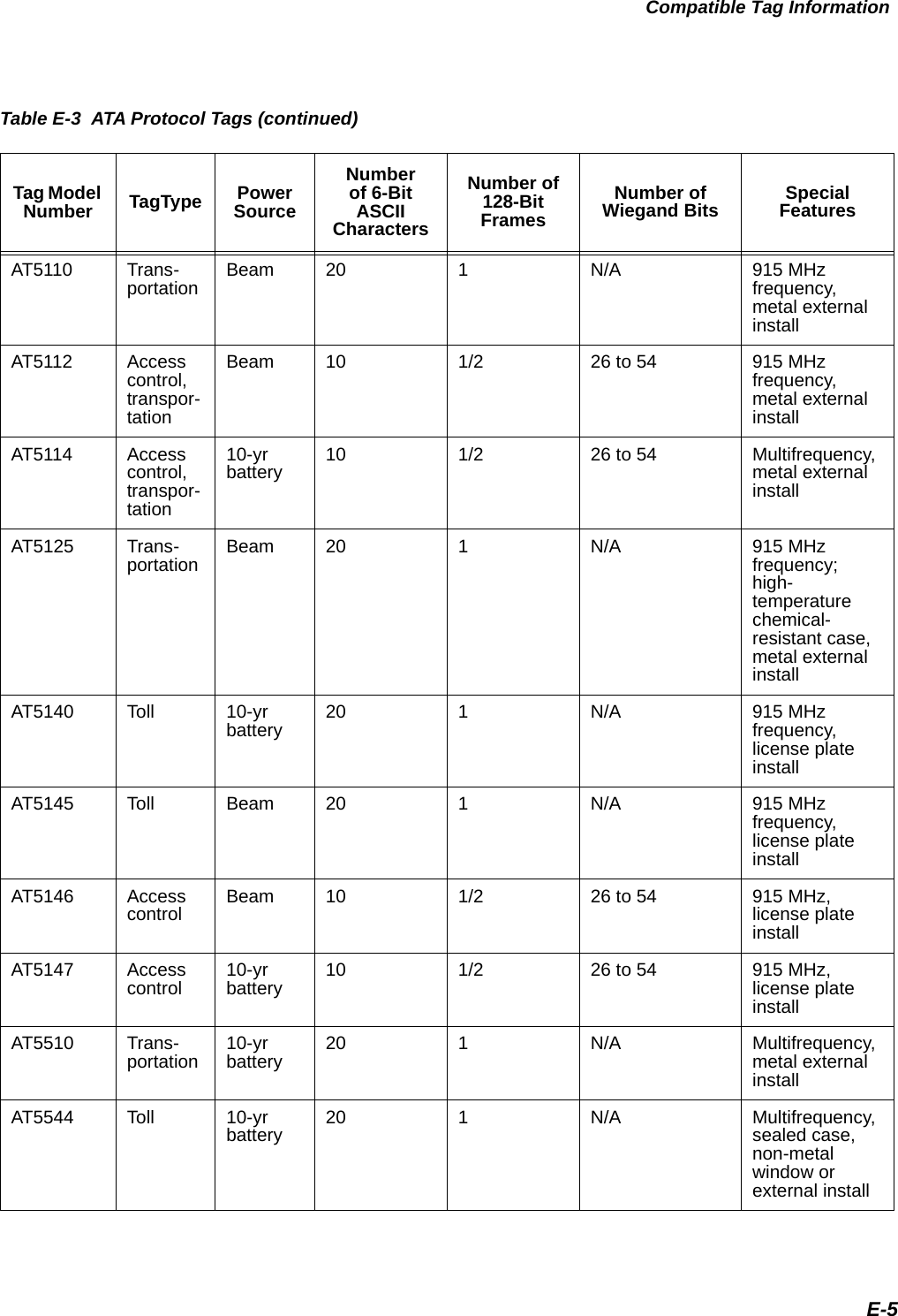
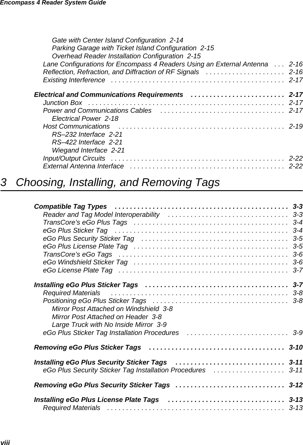
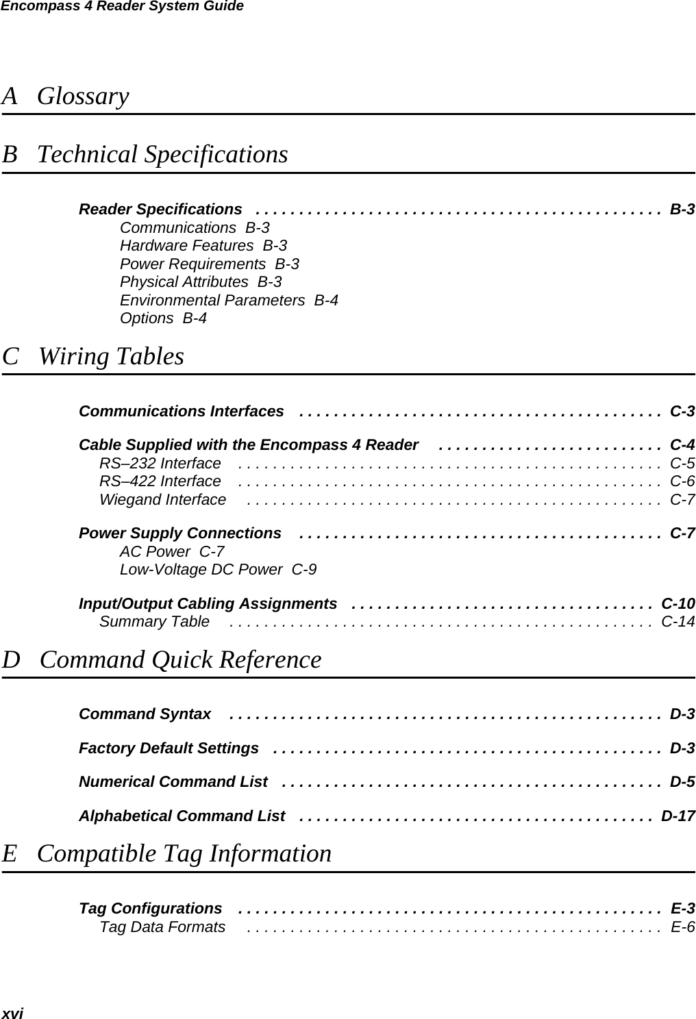
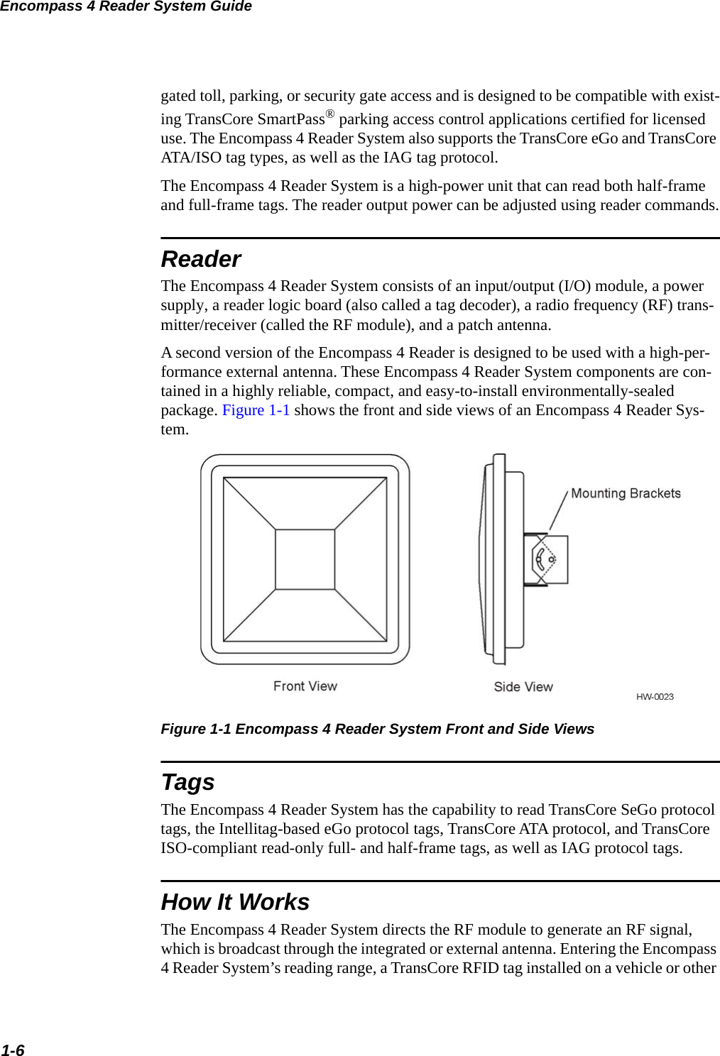
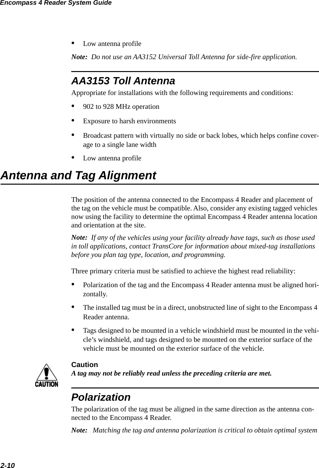
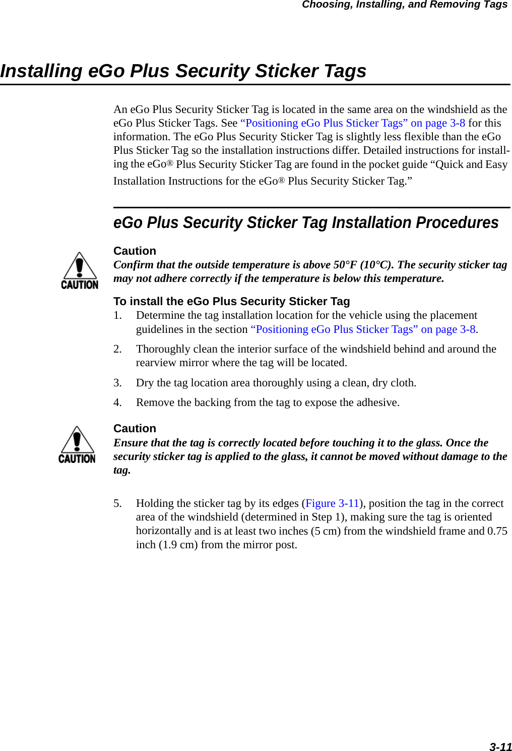
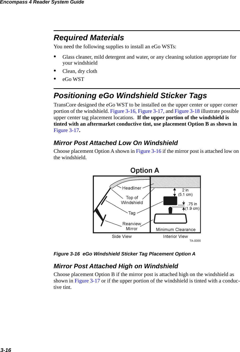
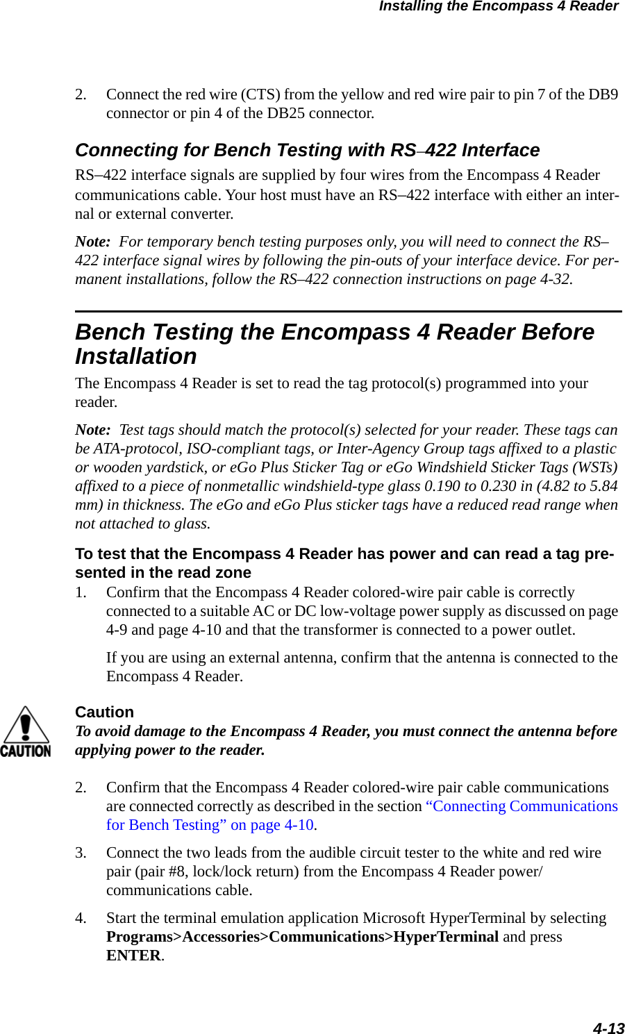
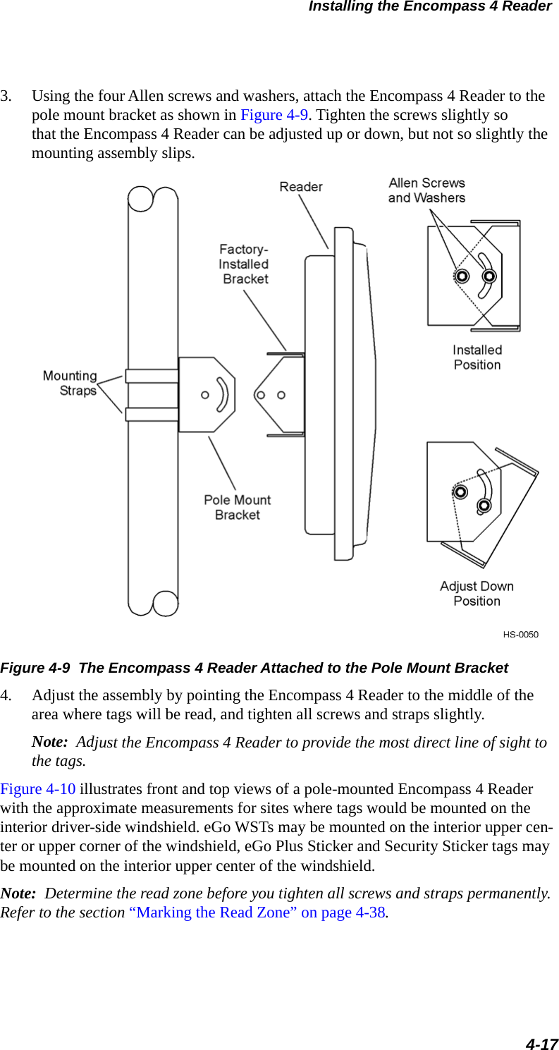
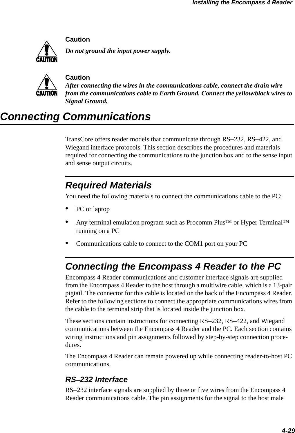
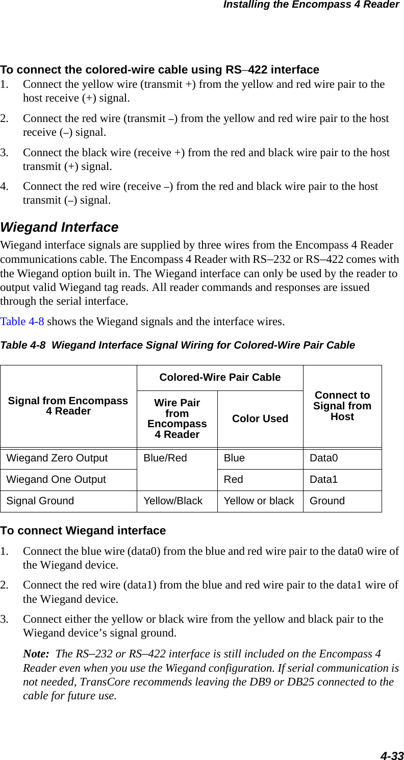
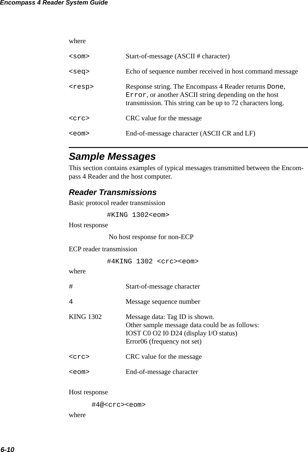
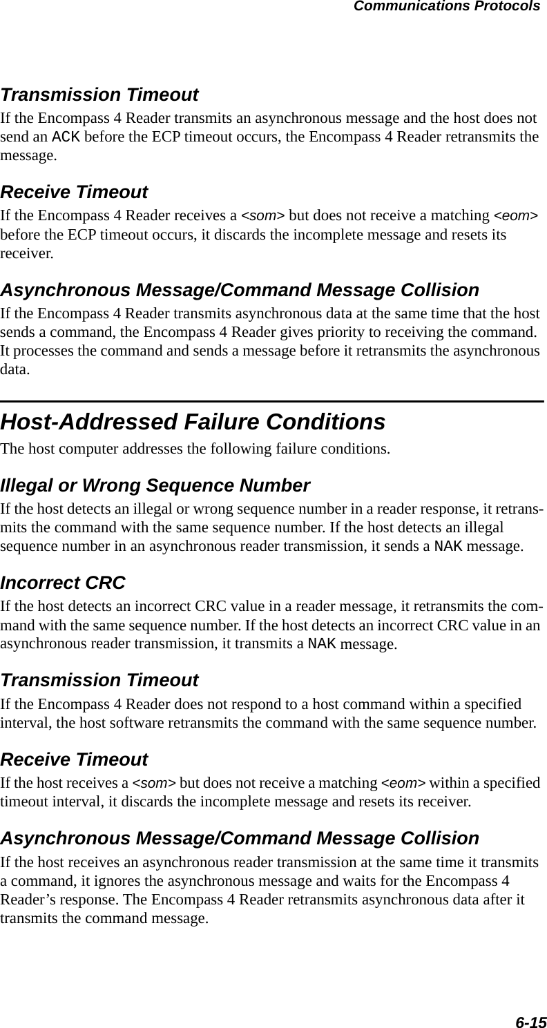
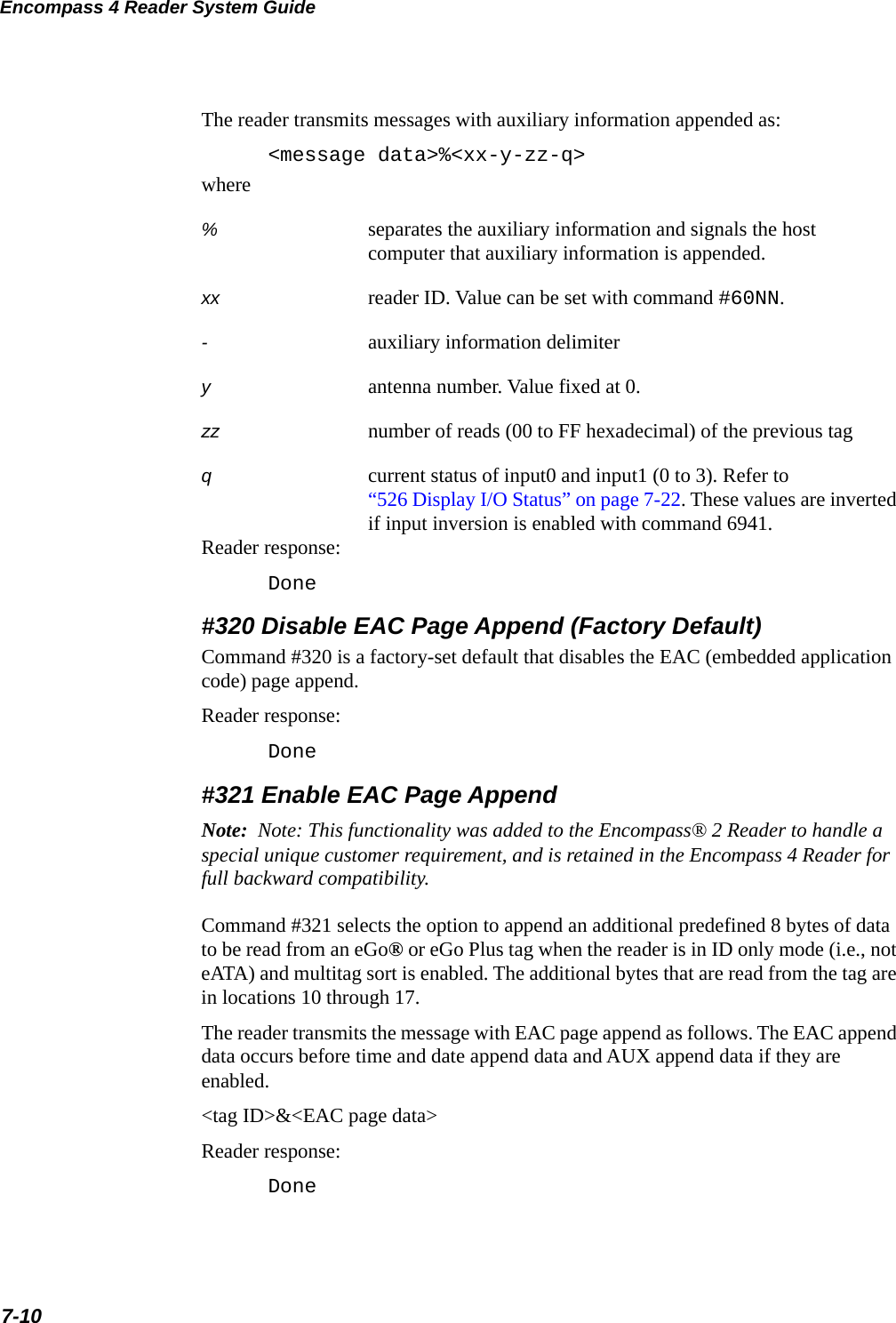
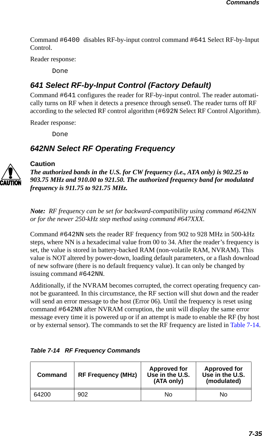
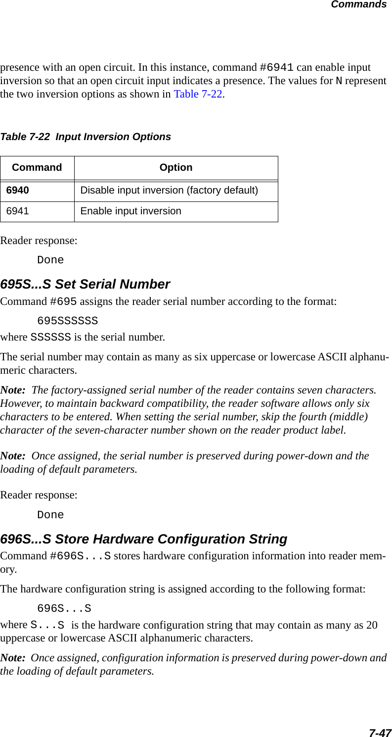
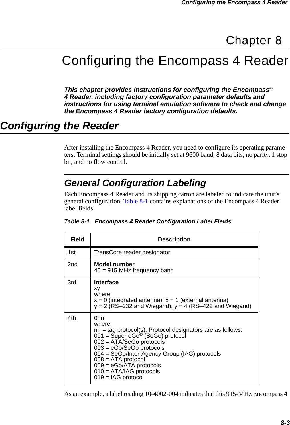
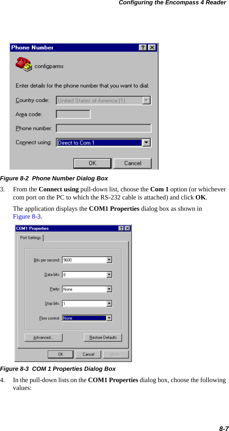
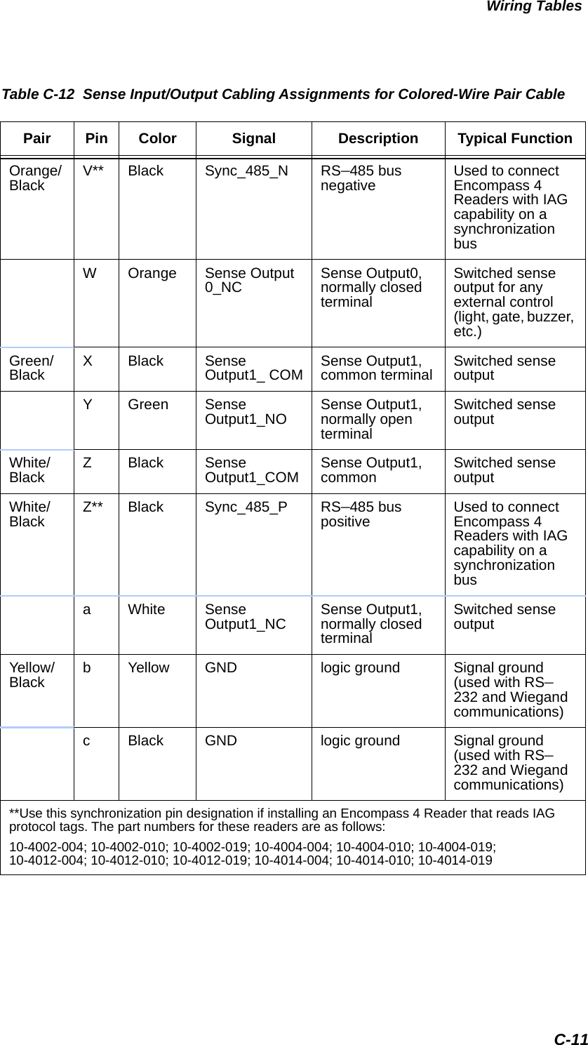
![Communications Protocols6-5Data Inquiry ProtocolData inquiry protocol is a basic protocol option that allows the host to control transmission of reader tag data. The selection of data inquiry protocol affects data mode operation. As the Encompass 4 Reader acquires tags, it buffers them but does not transmit them. Instead, the host must poll the Encompass 4 Reader for each tag by sending a CTRL-E character (hex 5 digit). The Encompass 4 Reader transmits one message (tag ID or report data) for each CTRL-E it receives until the buffer is empty.Each tag request message sent by the host consists only of the CTRL-E character; no som or eom characters are sent. Encompass 4 Reader data transmission (tag ID and report data) format is the same as for basic protocol.Selection of data inquiry protocol does not affect command mode operation.Basic Protocol and ECP FormatNote: In the following text, the symbols < and > are used to represent required vari-able message data, and the symbols [and] are used to represent optional data. These symbols are not part of the message syntax.Reader TransmissionsThe basic protocol format and the data inquiry protocol format are as follows:<som><data><eom>The ECP format is as follows:<som><seq><data><crc><eom>where<som> Start-of-message (ASCII # character)<seq> Sequence number (ASCII hex) that represents an even number in the range 0–9, A–F (0, 2, 4, 6, 8, A, C, E). The Encompass 4 Reader maintains the number. The host must acknowledge reader transmissions by sending an ACK message with the same sequence number received from the Encompass 4 Reader. The Encompass 4 Reader updates its sequence number upon receipt of a valid host ACK. If an ACK is not received, the Encompass 4 Reader retransmits the message. A reader transmission sequence is not considered complete until the Encompass 4 Reader receives an ACK and updates its sequence number.<data> An ASCII string up to 72 characters long. This string may contain tag data, a presence without tag report; an input status change report; an Error06, Error07, Error08, or Error11](https://usermanual.wiki/TransCore/0596465PT90/User-Guide-3159238-Page-141.png)
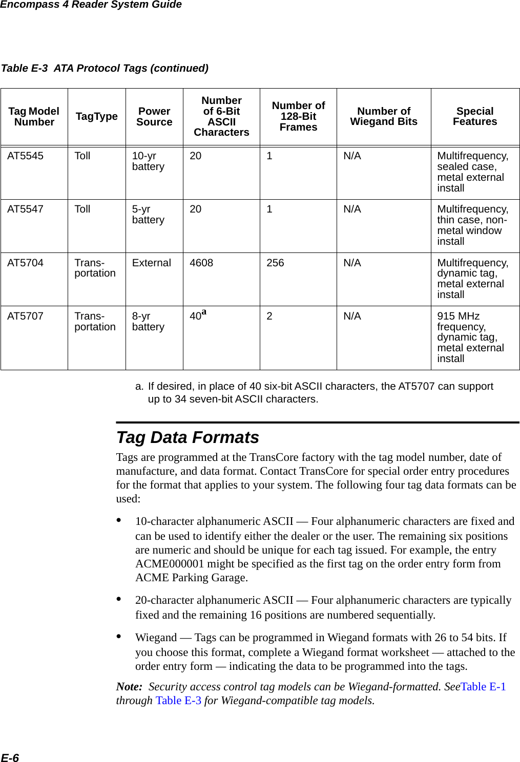
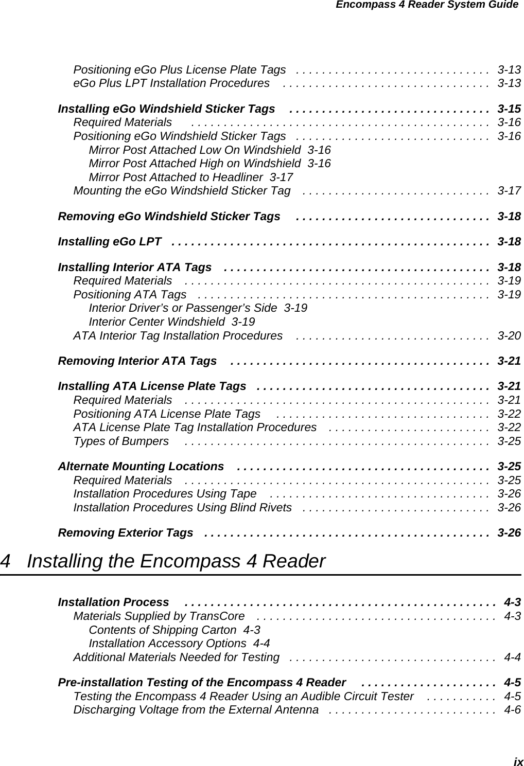
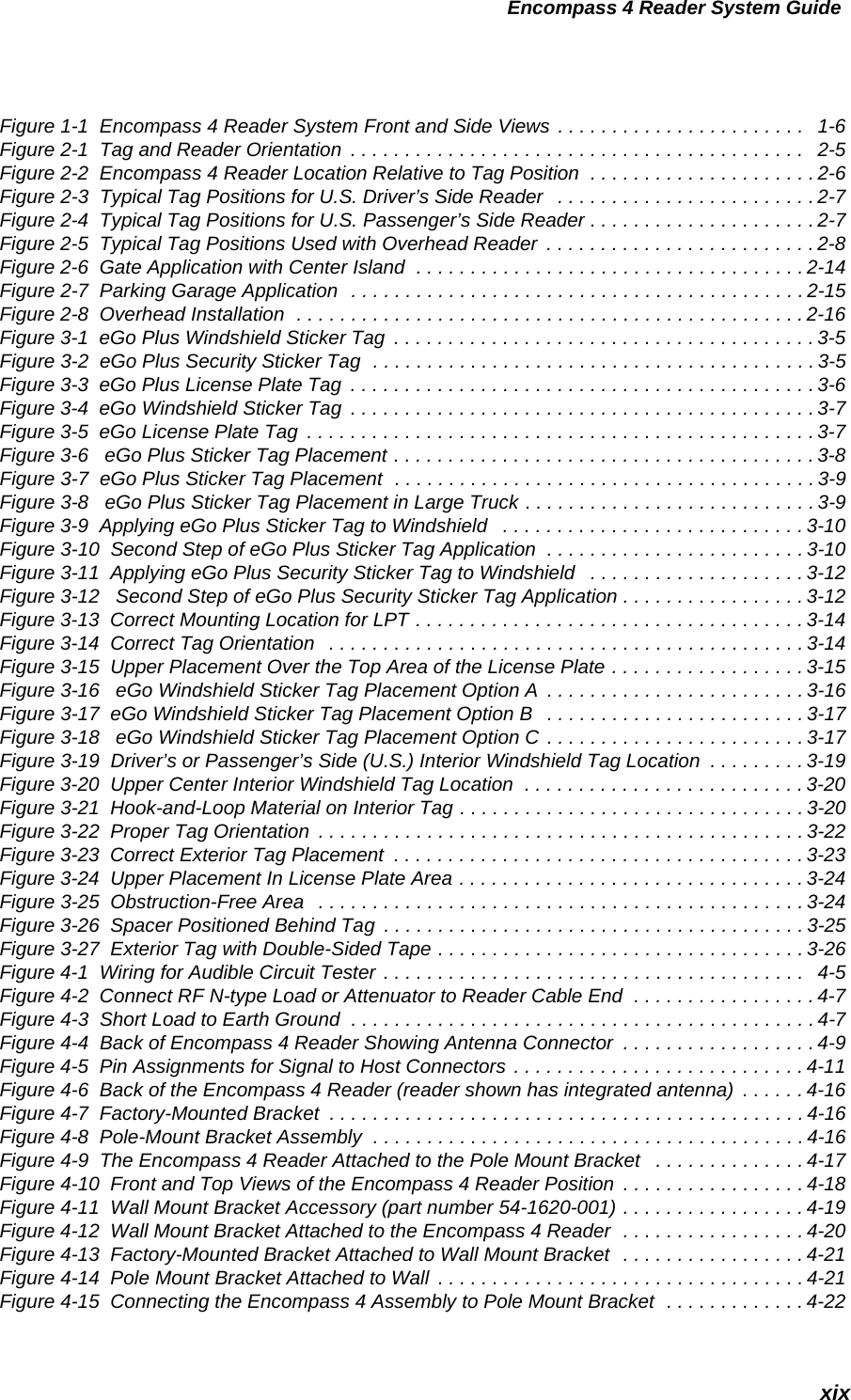
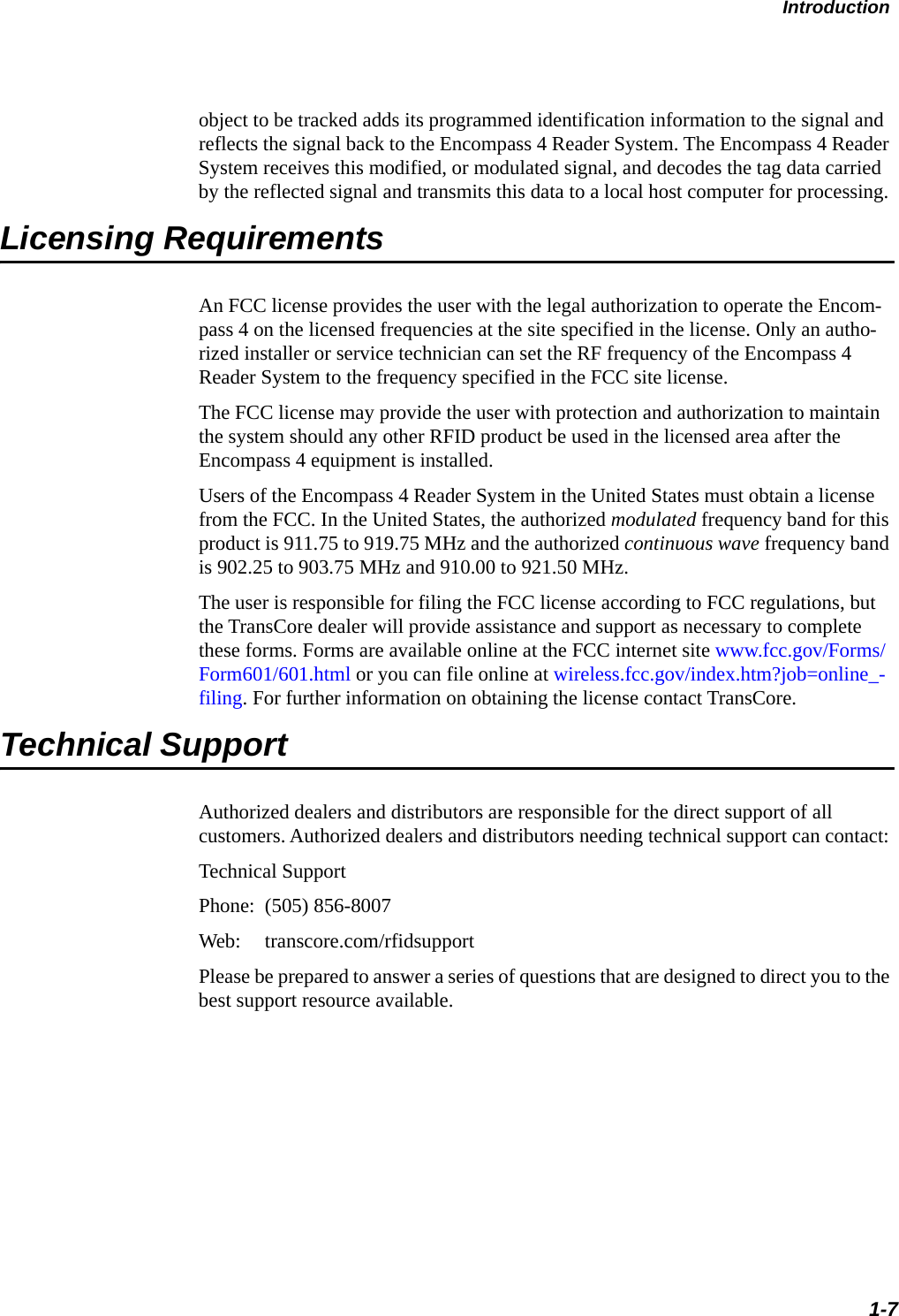
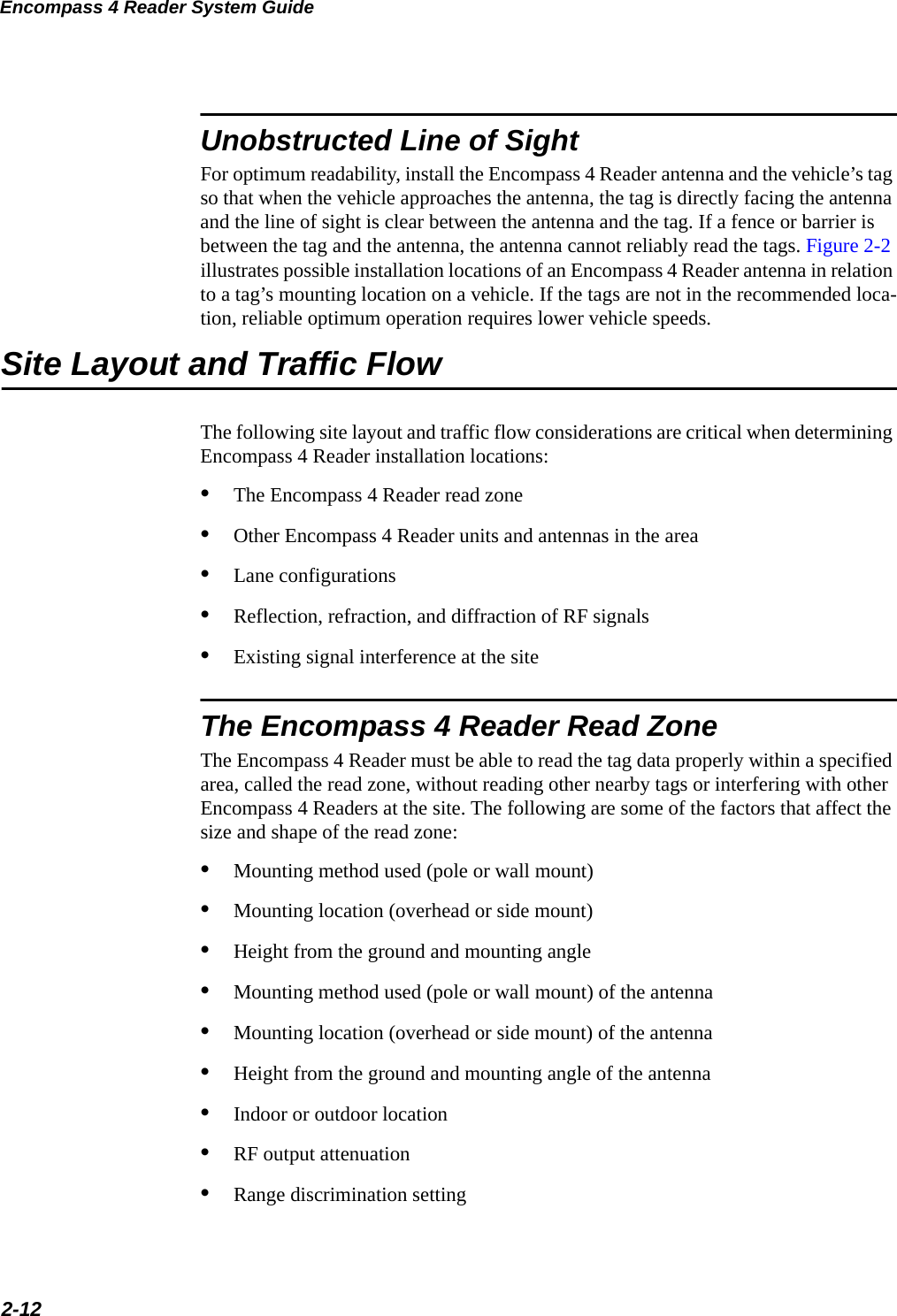
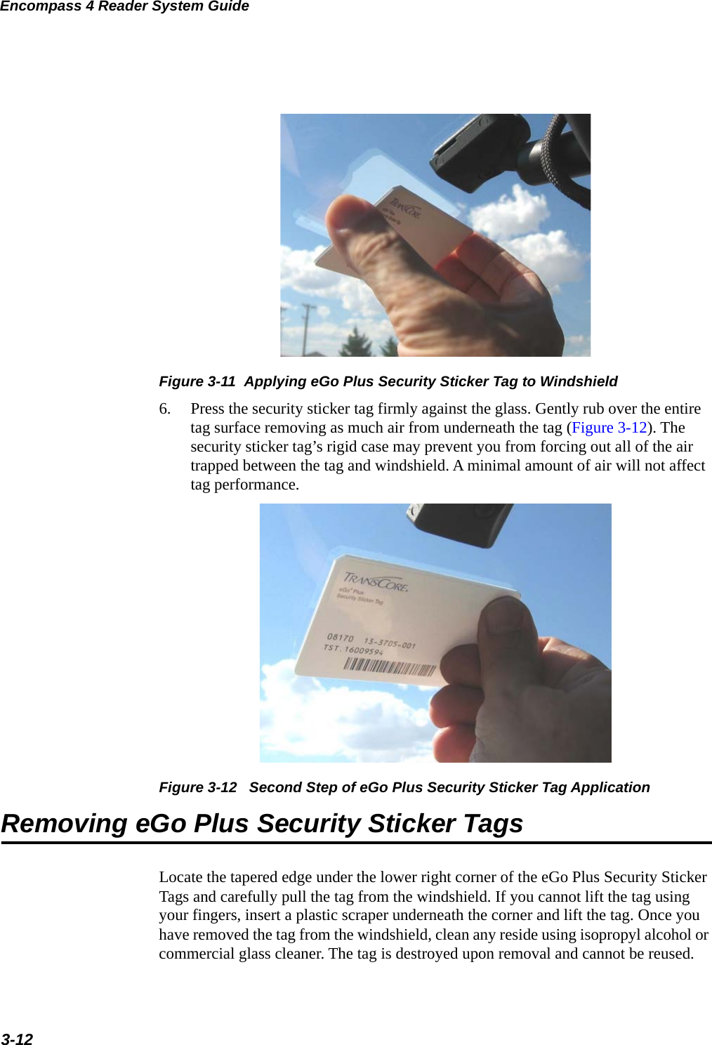
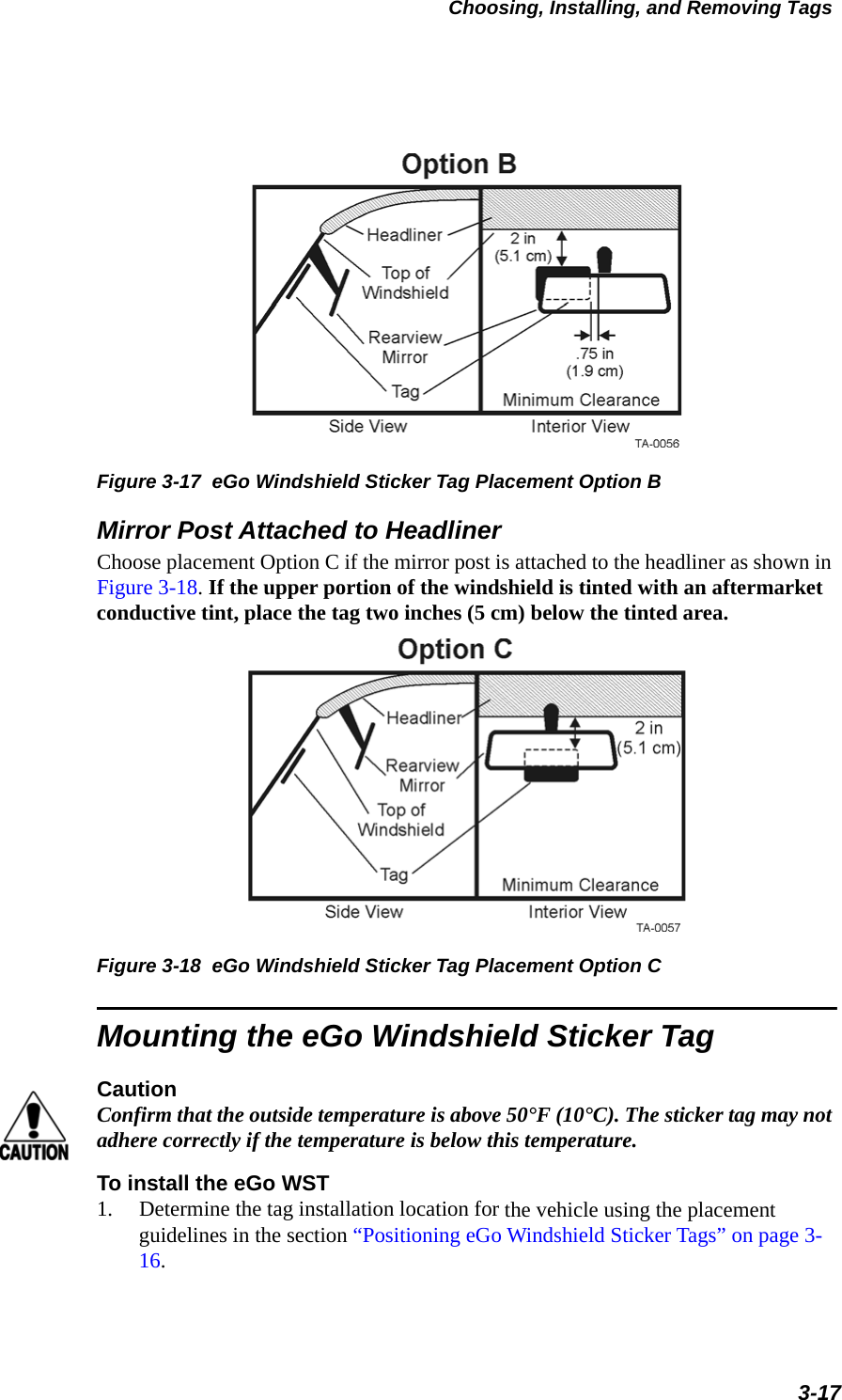
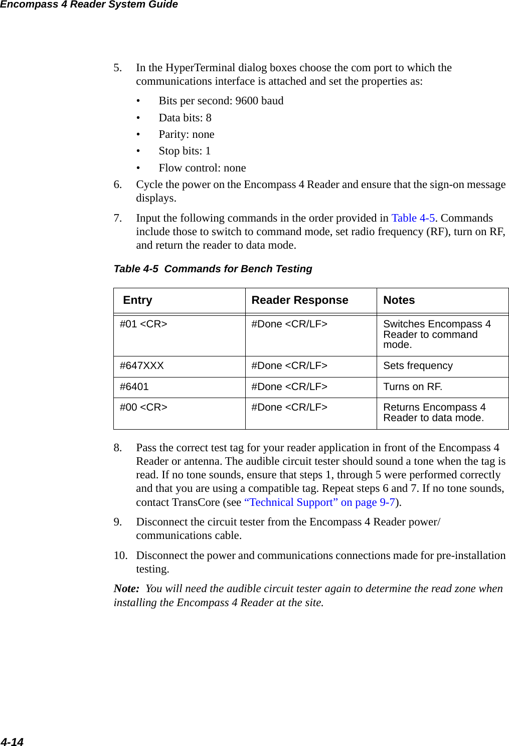
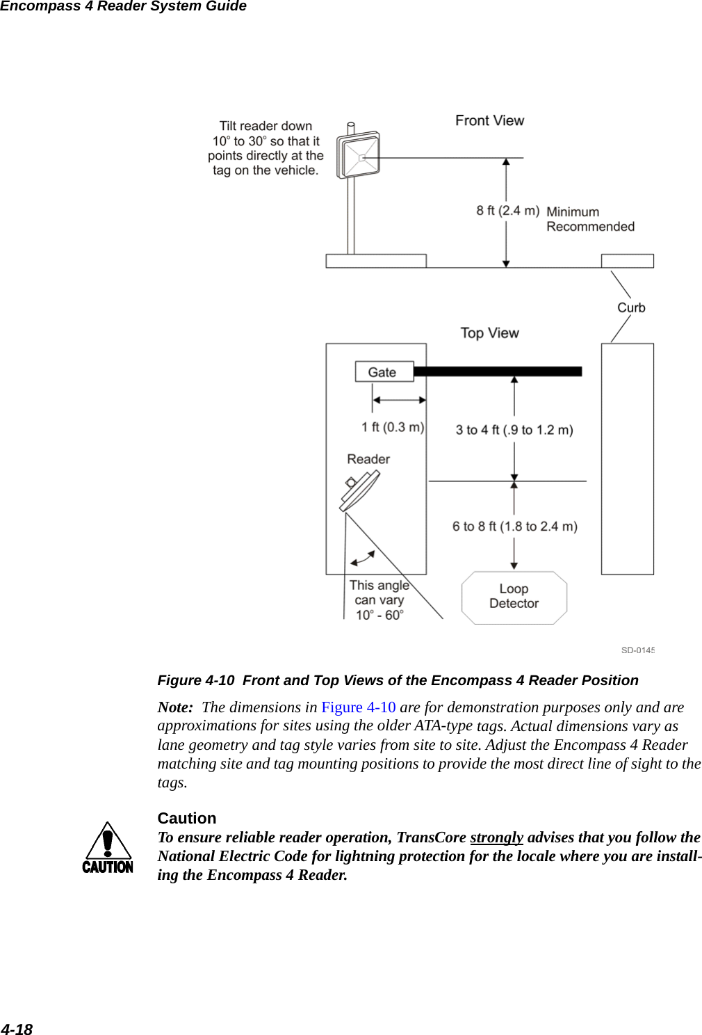
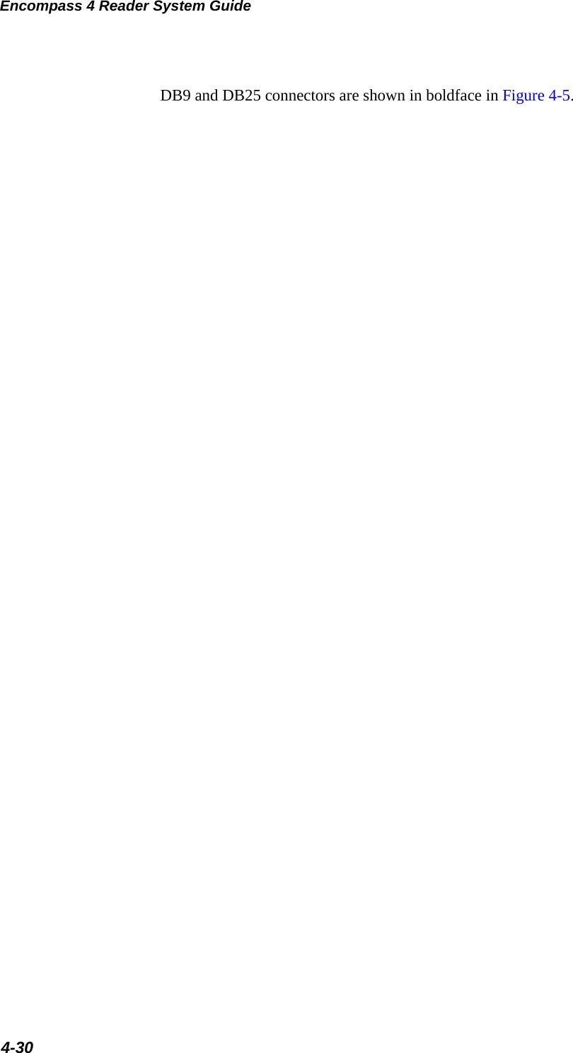
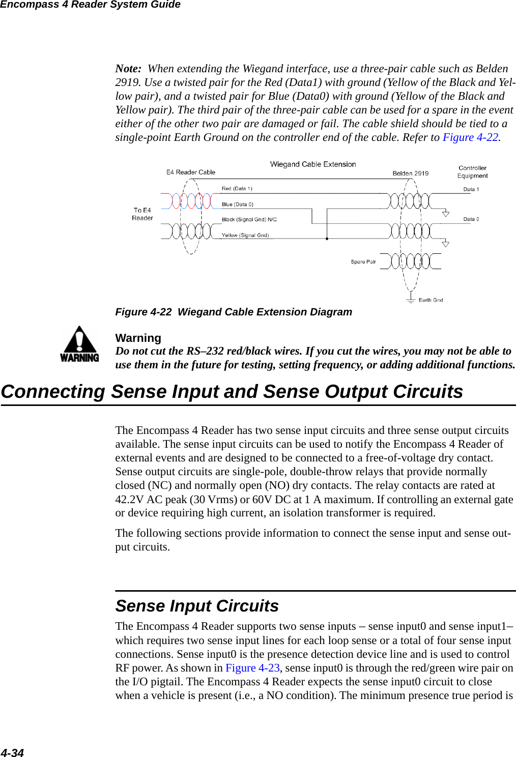
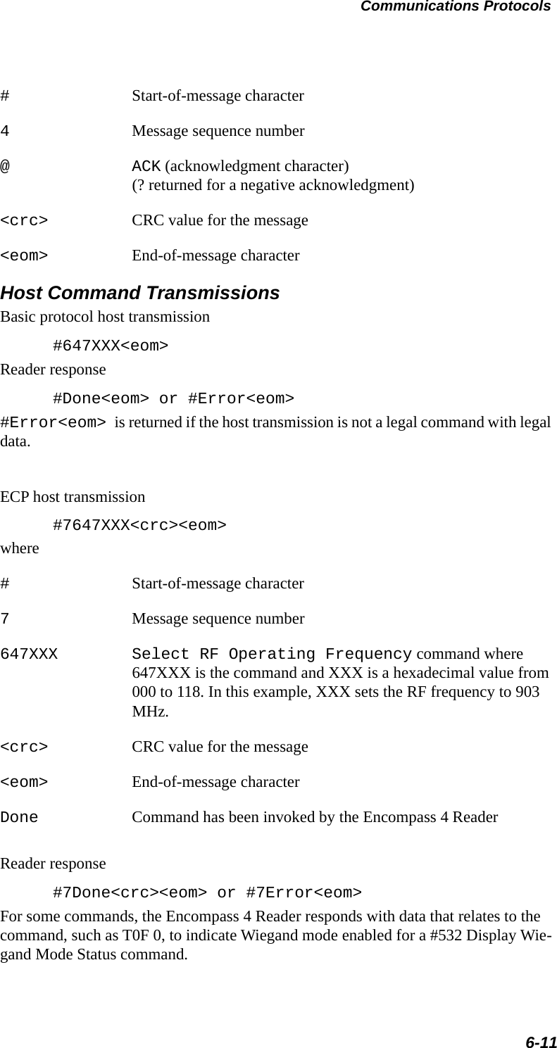
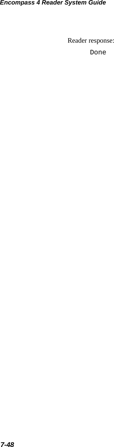
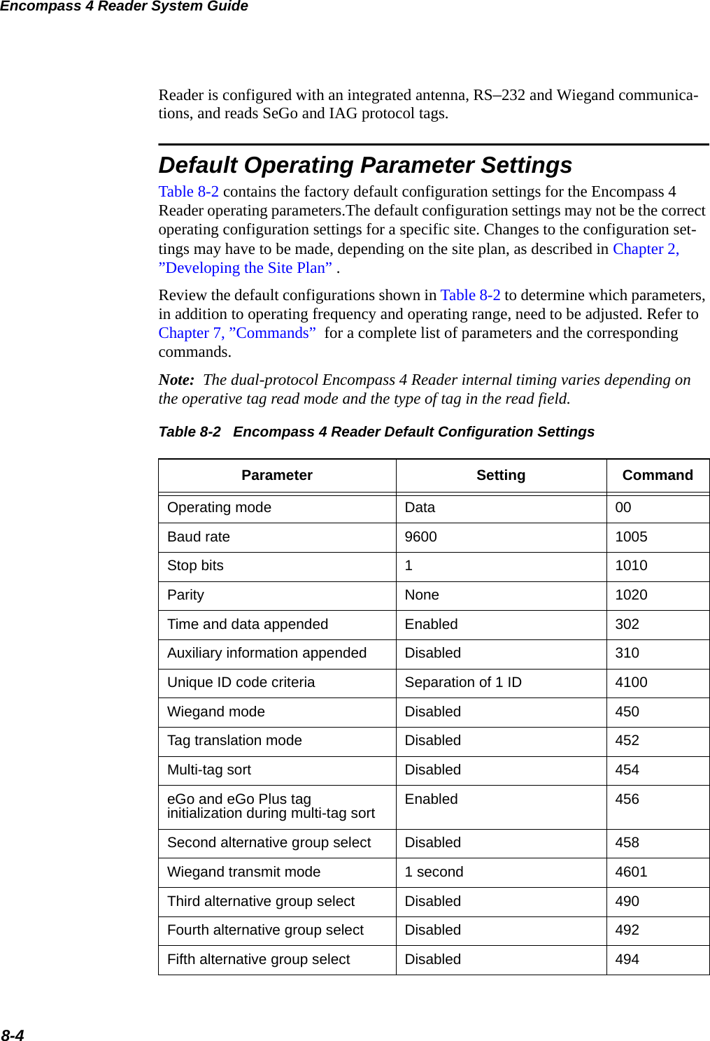
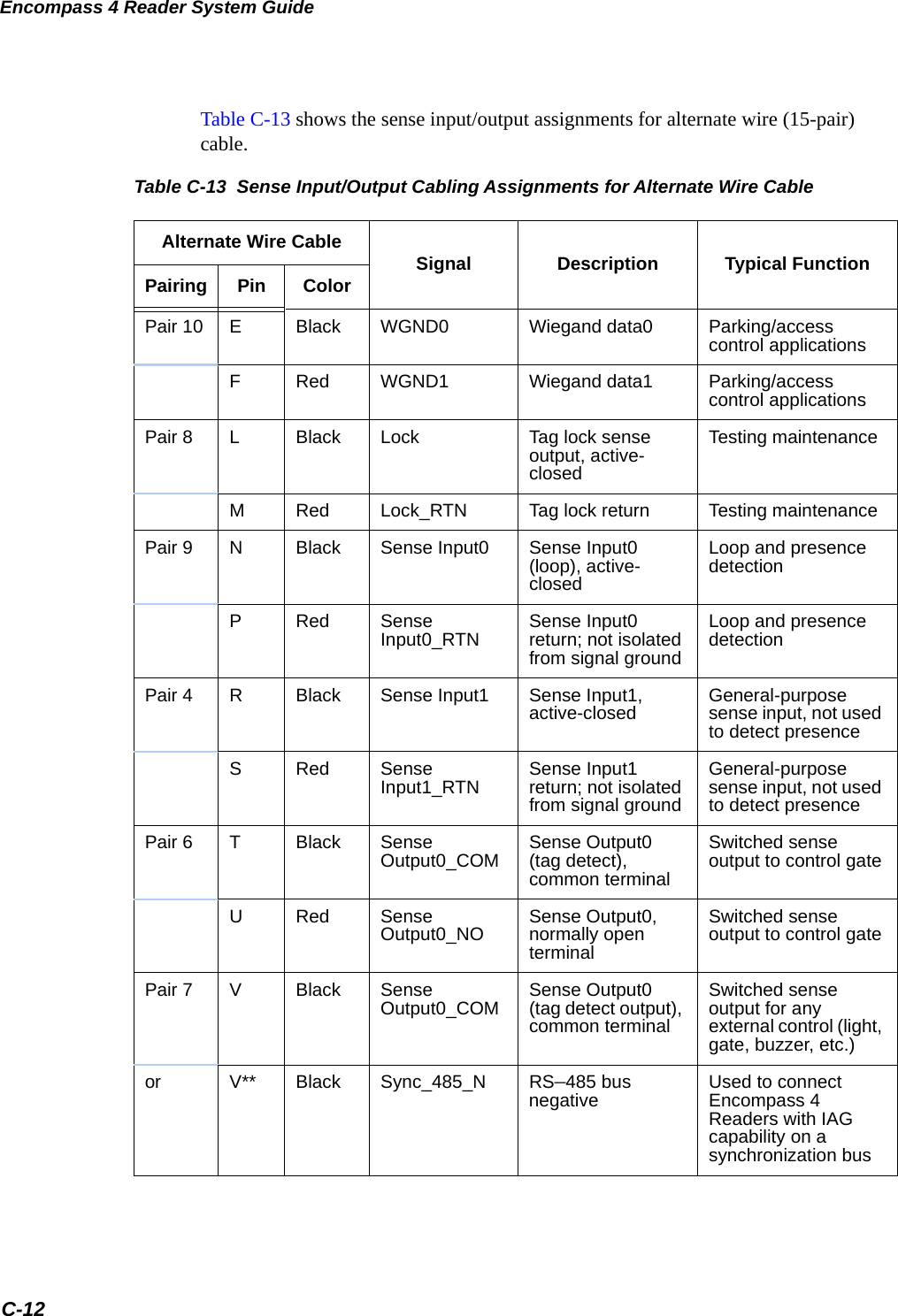
![Encompass 4 Reader System Guide6-8Host TransmissionThe host computer initiates synchronous communications between the Encompass 4 Reader and the host. The host begins a sequence by issuing a command; the Encom-pass 4 Reader responds accordingly.The data inquiry protocol format is as follows:<CTRL-E>The basic protocol format is as follows:<som><cmd>[<data>]<eom>The ECP format is as follows:<som><seq><cmd>[<data>]<crc><eom>where<CTRL-E> ASCII Control E (hex 5 digit). When in data inquiry mode, each transmission of a CTRL-E by the host causes the Encompass 4 Reader to transmit one tag ID.<som> Start-of-message (ASCII # character)<seq> Sequence number (ASCII hex digit) that represents an odd number in the range 0–9, A–F (1, 3, 5, 7, 9, B, D, F). The host should use odd sequence numbers in its command since the Encompass 4 Reader uses even sequence numbers in its transmissions. This method eliminates the possibility of a synchronous host command and an asynchronous reader transmission having the same sequence number.Upon receiving a host command in ECP, the Encompass 4 Reader replies using the command’s sequence number in its response. Therefore, the host computer updates its sequence number upon receipt of a valid reader message. If the sequence number is not updated before transmission of the next command, the Encompass 4 Reader will not service the new command; it will retransmit its previous message. A command/message sequence is not complete until the host updates its sequence number.<cmd> Command code, a string that contains from two to four ASCII hex characters[<data>] Optional data field, an ASCII string of as many as 20 characters in length. For example, the store hardware configuration string command is #696S...S or command #696 Store Hardware Configuration String followed by the data string S...S.<crc> CRC value for the message](https://usermanual.wiki/TransCore/0596465PT90/User-Guide-3159238-Page-144.png)
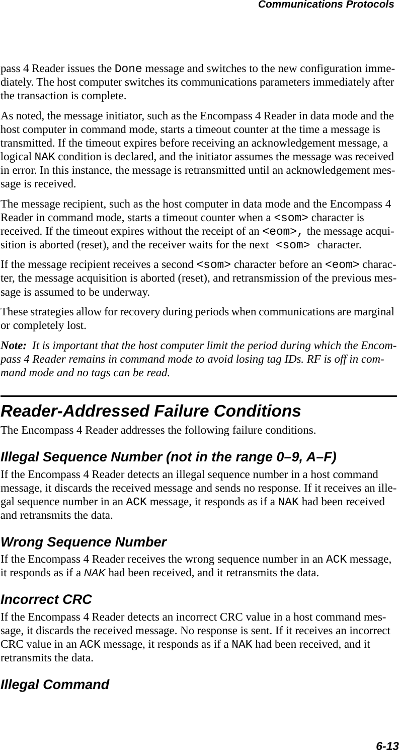
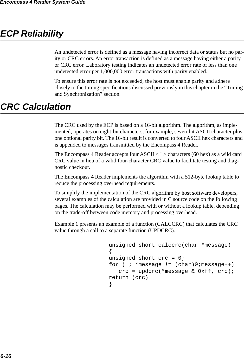
![Encompass 4 Reader System Guide6-12#7Error<eom> will be returned if host transmission is not a legal command with legal data.Timing and SynchronizationThe ECP is largely independent of baud rate. The timeout delays previously described are a function of baud rate.The Encompass 4 Reader supports an ECP timeout, which applies equally to both transmit and receive. The receiver’s minimum timeout delay equals the time to transmit/receive the longest anticipated message at the current baud rate setting. Additional margin should be included for idle periods between characters; for example, processing overhead, if any. The timeout delay period can be expressed as follows:rec (ms) = L x [char + idle]wherechar (ms) 1000 x [ Bc / Rb ]BcBits per character, typically 10RbBaud rate, 1200–38.4 KLLength of message in charactersidle Maximum idle period between characters (ms)Note: The Encompass 4 Reader supports baud rates between 1200 and 38.4 K.Likewise, the sender must set a timeout delay equal to the delay of nine characters at the current baud rate setting. For example, the time required to shift out the <eom> character plus the time to shift in the ACK or NAK message to be received plus a pro-cessing allowance for the receiver to process the message and check for error condi-tions.Thus, the sending timeout delay can be expressed as follows:send (ms) = 9 * char + errchkwhereerrckh (ms) Processing period to perform error checking by receiverThe host computer can remotely set the Encompass 4 Reader’s communications parameters while in the command mode, but TransCore does not recommend this action if communications conditions are marginal.After the Encompass 4 Reader receives new communications parameters, the Encom-](https://usermanual.wiki/TransCore/0596465PT90/User-Guide-3159238-Page-148.png)
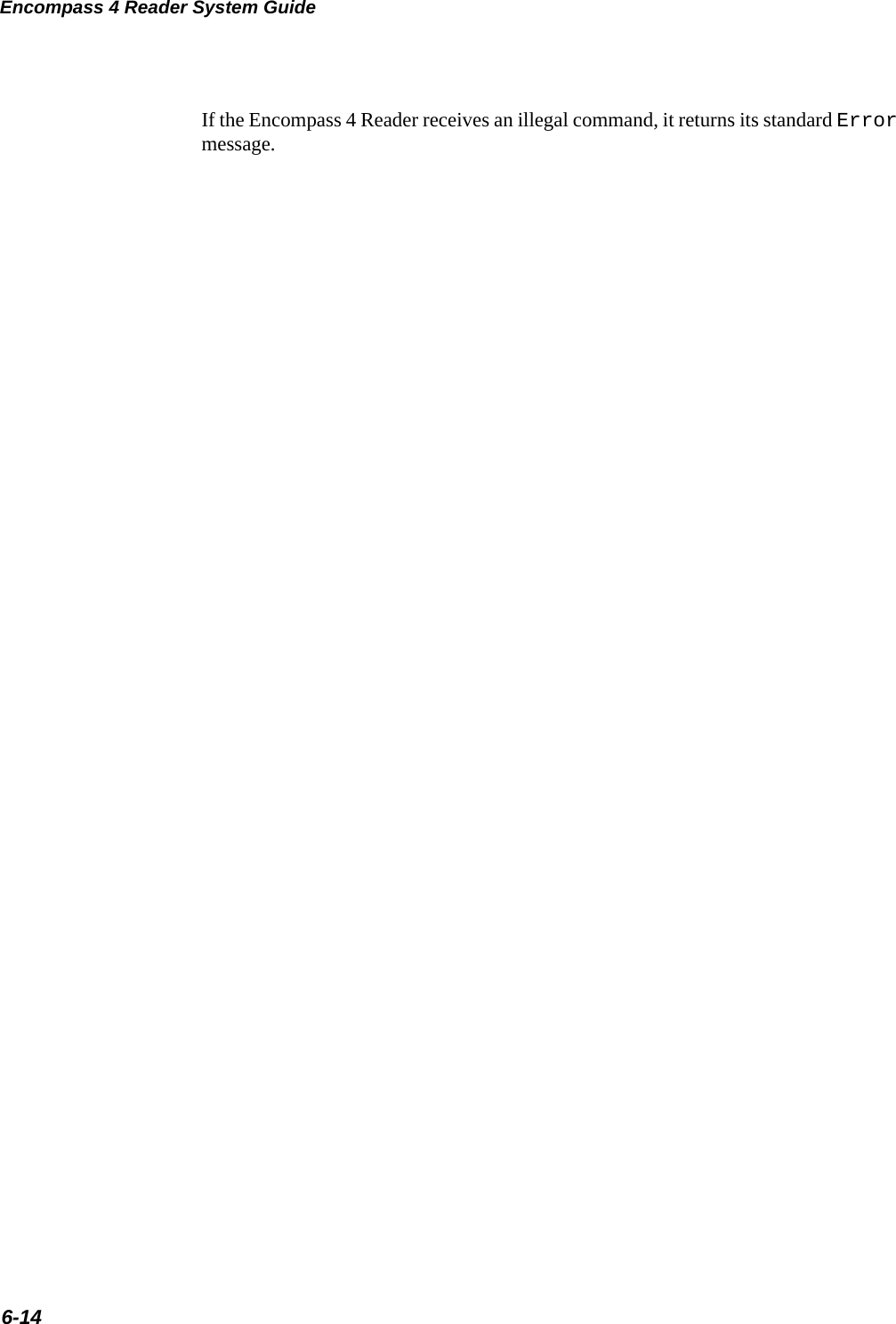
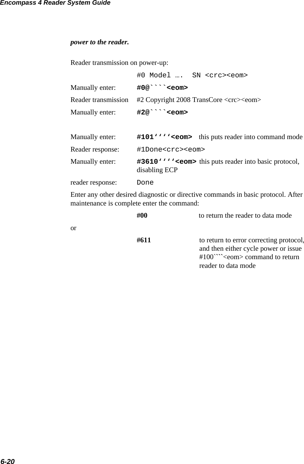
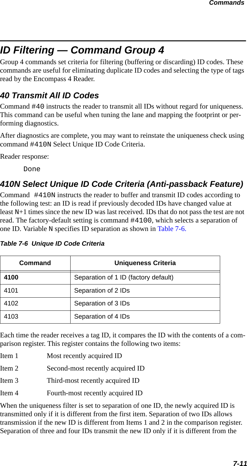
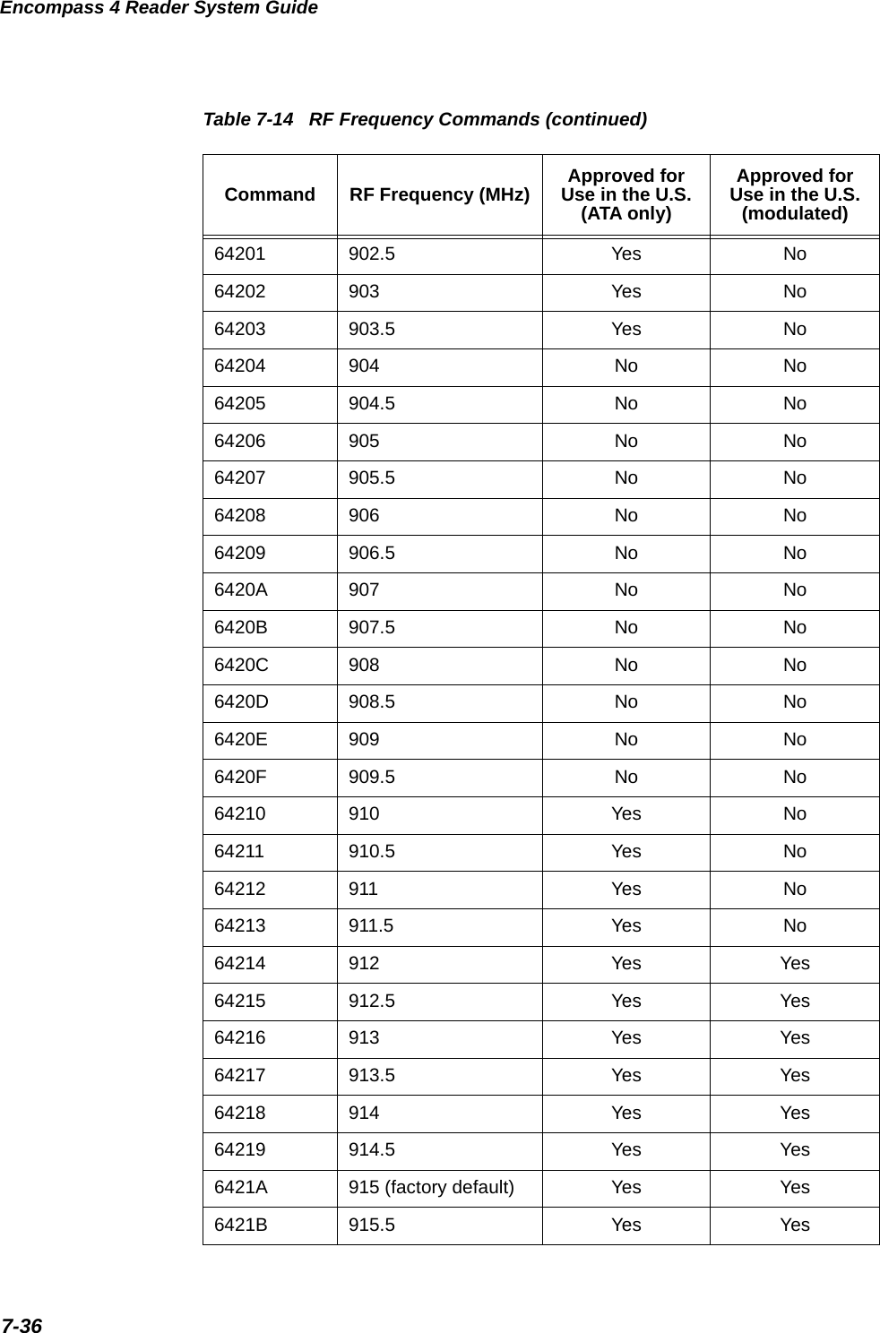
![Example 2 shows an example of UPDCRC that does not require a lookup table.#define BITS_PER_CHAR 8unsigned short updcrc (unsigned short ch, unsigned short crc){register short counter = BITS_PER_CHAR;register short temp = crc;while (--counter >= 0) if (temp & 0x8000) {temp <<= 1;temp += (((ch <<= 1) & 0x0100) != 0);temp ^= 0x1021; } else {temp <<= 1;temp += (((ch <<= 1) & 0x0100) != 0); }return(temp);}Communications Protocols6-17Example 3 contains an example of UPDCRC that does require a lookup table. #define updcrc(cp, crc)( crctab[((crc >> 8) & 255)]^ (crc << 8) ^ cpstatic unsigned short crctab [256] = {0x0000, 0x1021, 0x2042, 0x3063, 0x4048, 0x50a5, 0x60c6, 0x70e7,0x8108, 0x9129, 0xa14a, 0xb16b, 0xc18c, 0xd1ad, 0xe1ce, 0xf1ef,0x1231, 0x0210, 0x3273, 0x2252, 0x52b5, 0x4294, 0x72f7, 0x62d6,0x9339, 0x8318, 0xb37b, 0xa35a, 0xd3bd, 0xc39c, 0xf3ff, 0xe3de,0x2462, 0x3443, 0x0420, 0x1401, 0x64e6, 0x74c7, 0x44a4, 0x5485,0xa56a, 0xb54b, 0x8528, 0x9509, 0xe5ee, 0xf5cf, 0xc5ac, 0xd58d,0x3653, 0x2672, 0x1611, 0x0630, 0x76d7, 0x66f6, 0x5695, 0x46b4,0xb75b, 0xa77a, 0x9719, 0x8738, 0xf7df, 0xe7fe, 0xd79d, 0xc7bc,0x48c4, 0x58e5, 0x6886, 0x78a7, 0x0840, 0x1861, 0x2802, 0x3823,0xc9cc, 0xd9ed, 0xe98e, 0xf9af, 0x8948, 0x9969, 0xa90a, 0xb92b,0x5af5, 0x4ad4, 0x7ab7, 0x6a96, 0x1a71, 0x0a50, 0x3a33, 0x2a12,0xdbfd, 0xcbdc, 0xfbbf, 0xeb9e, 0x9b79, 0x8b58, 0xbb3b, 0xab1a,0x6ca6, 0x7c87, 0x4ce4, 0x5cc5, 0x2c22, 0x3c03, 0x0c60, 0x1c41,0xedae, 0xfd8f, 0xcdec, 0xddcd, 0xad2a, 0xbd0b, 0x8d68, 0x9d49,0x7e97, 0x6eb6, 0x5ed5, 0x4ef4, 0x3e13, 0x2e32, 0x1e51, 0x0e70,0xff9f, 0xefbe, 0xdfdd, 0xcffc, 0xbf1b, 0xaf3a, 0x9f59, 0x8f78,0x9188, 0x81a9, 0xb1ca, 0xa1eb, 0xd10c, 0xc12d, 0xf14e, 0xe16f,](https://usermanual.wiki/TransCore/0596465PT90/User-Guide-3159238-Page-153.png)
![Encompass 4 Reader System Guide6-18Example 4 shows an example of a function that creates the lookup table.#include <stdio.h>#define MAX_CHAR 256#define BITS_CHAR 8#define SIGN_BIT 0x8000#define POLY 0x1021unsigned short crctab [MAX_CHAR];main (){unsigned short ch;unsigned short workval;unsigned short bit;unsigned short carry;for (ch = 0; ch != MAX_CHAR; ch++) {workval = ch << BITS_CHAR;for (bit = BITS_CHAR; bit != 0; bit--) {carry = (workval & SIGN_BIT);workval <<= 1;if (carry)workval ^= POLY;}crctab[ch] = workval;0x1080, 0x00a1, 0x30c2, 0x20e3, 0x5004, 0x4025, 0x7046, 0x6067,0x83b9, 0x9398, 0xa3fb, 0xb3da, 0xc33d, 0xd31c, 0xe37f, 0xf35e,0x02b1, 0x1290, 0x22f3, 0x32d2, 0x4235, 0x5214, 0x6277, 0x7256,0xb5ea, 0xa5cb, 0x95a8, 0x8589, 0xf56e, 0xe54f, 0xd52c, 0xc50d,0x34e2, 0x24c3, 0x14a0, 0x0481, 0x7466, 0x6447, 0x5424, 0x4405,0xa7db, 0xb7fa, 0x8799, 0x97b8, 0xe75f, 0xf77e, 0xc71d, 0xd73c,0x26d3, 0x36f2, 0x0691, 0x16b0, 0x6657, 0x7676, 0x4615, 0x5634,0xd94c, 0xc96d, 0xf90e, 0xe92f, 0x99c8, 0x89e9, 0xb98a, 0xa9ab,0x5844, 0x4865, 0x7806, 0x6827, 0x18c0, 0x08e1, 0x3882, 0x28a3,0xcb7d, 0xdb5c, 0xeb3f, 0xfb1e, 0x8bf9, 0x9bd8, 0xabbb, 0xbb9a,0x4a75, 0x5a54, 0x6a37, 0x7a16, 0x0af1, 0x1ad0, 0x2ab3, 0x3a92,0xfd2e, 0xed0f, 0xdd6c, 0xcd4d, 0xbdaa, 0xad8b, 0x9de8, 0x8dc9,0x7c26, 0x6c07, 0x5c64, 0x4c45, 0x3ca2, 0x2c83, 0x1ce0, 0x0cc1,0xef1f, 0xff3e, 0xcf5d, 0xdf7c, 0xaf9b, 0xbfba, 0x8fd9, 0x9ff8,0x6e17, 0x7e36, 0x4e55, 0x5e74, 0x2e93, 0x3eb2, 0x0ed1, 0x1ef0,};](https://usermanual.wiki/TransCore/0596465PT90/User-Guide-3159238-Page-154.png)
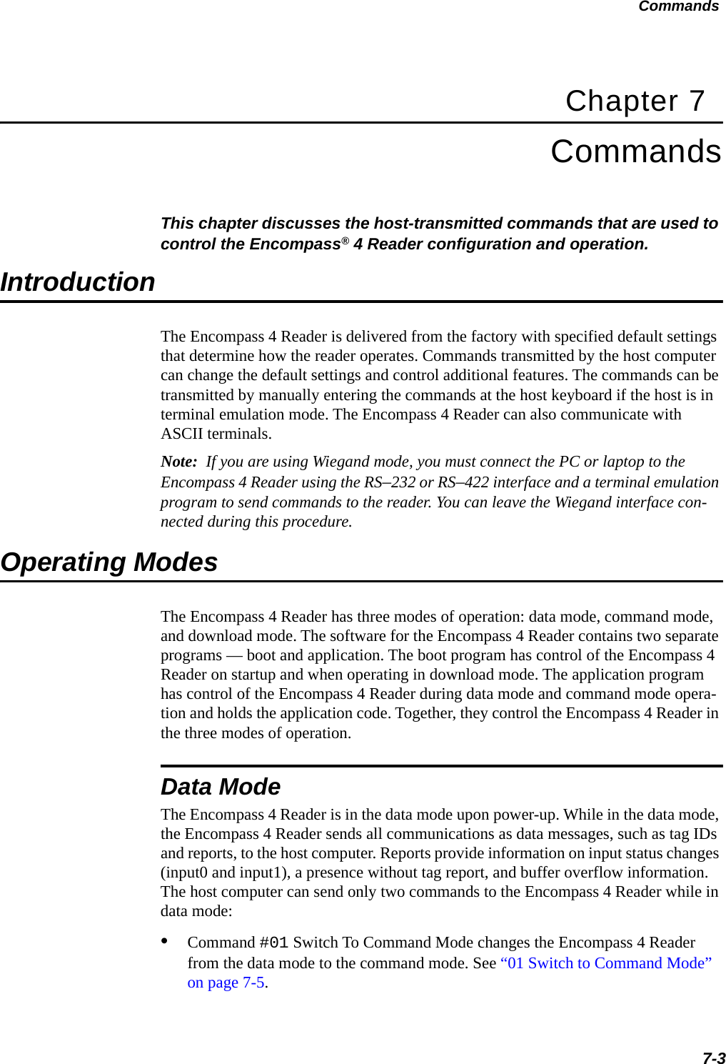
![Communications Protocols6-19}for (ch = 0; ch != MAX_CHAR; ch++)printf("0x%04x\n", crctab[ch]);}Manually Disabling ECP for MaintenanceUnder certain conditions, communications between the host and Encompass 4 Reader may be lost temporarily and maintenance may be required. The reader or host is send-ing out a message and waiting for an acknowledgment. When the acknowledgment is not received, the message is sent again. Additional messages are also buffered. Often the first indication that the Encompass 4 Reader software is in an ECP “loop” is when the user/technician sees a recurring display of the same message repeated over and over again on the monitor. The procedure described in the following paragraphs enables the maintenance technician to change configuration or test tag reading manu-ally.Assuming that the ECP timeout is at the factory default of 12.7 seconds (or other value that allows enough time for the commands to be manually entered) the following com-mand sequence may be used to break out of an ECP loop. This command sequence uses four ASCII < ` > characters (60 hex) as wild card CRC values.Note: The ASCII <`> character (60 hex) is commonly located on the ~ key.You must acknowledge existing messages by issuing commands with the generic for-mat:#x@‘‘‘‘<eom>where#Start-of-message characterxMessage sequence number. This must be the same as the sequence number of the message being acknowledged@ACK (acknowledgment character)<‘‘‘‘> Wild card CRC value for the message<eom> End-of-message characterThe following is a typical sequence after power-on limiting buffered messages.Note: Ensure that no tags are in the field when you are performing this troubleshoot-ing procedure.CautionTo avoid damage to the Encompass 4 Reader that uses an external antenna, ensure that you have connected the antenna or a dummy load to the reader before applying](https://usermanual.wiki/TransCore/0596465PT90/User-Guide-3159238-Page-155.png)


![Encompass 4 Reader System Guide7-12first three and the first four items, respectively.Note: A new ID can fail the filter test and not be transmitted; however, it remains stored in the comparison register.The uniqueness test’s time limit is set by Command #441. If an ID is buffered, it will not be accepted again unless it arrives at the reader more than the programmed time interval from the previous arrival or until the receipt of one or more other IDs reset the uniqueness. Reader response:Done420N Select Valid ID Code CriteriaCommand #420N directs the reader to validate an ID received only after it has been obtained a specified number of times in sequence. Values for N are 0 through 3 (Table 7-7). The factory setting is one acquisition (N = 0).Table 7-7 Select Valid Code Commands and FramesCommand Valid Code Frames4200 1 (factory default)4201 24202 34203 4The validation procedure is executed before the unique ID test (Select Unique ID Code Criteria [#410N] commands). IDs that do not pass the validation test are not reported.For example, command #4203 specifies that the same ID must be obtained from the antenna/RF module 4 times in succession before it is considered for the uniqueness test. This feature is useful in installations where RF reflections may cause a single tag to be read multiple times or where an occasional ID might be read from fringe areas440 Reset UniquenessCommand 440 causes the ID filtering process set by Select Unique ID Code Criteria (#410N) to restart. It is used in conjunction with the Variable Timeout #44N) com-mands. This command provides a method to end all uniqueness timers.44N Set Uniqueness TimeoutPlaces a time limit on the uniqueness criterion set by Select Unique ID Code Criteria (#410N). The parameter N sets the number of minutes on the timeout clock. The fac-tory setting is two minutes (N = 1).Command Timeout Clock](https://usermanual.wiki/TransCore/0596465PT90/User-Guide-3159238-Page-168.png)


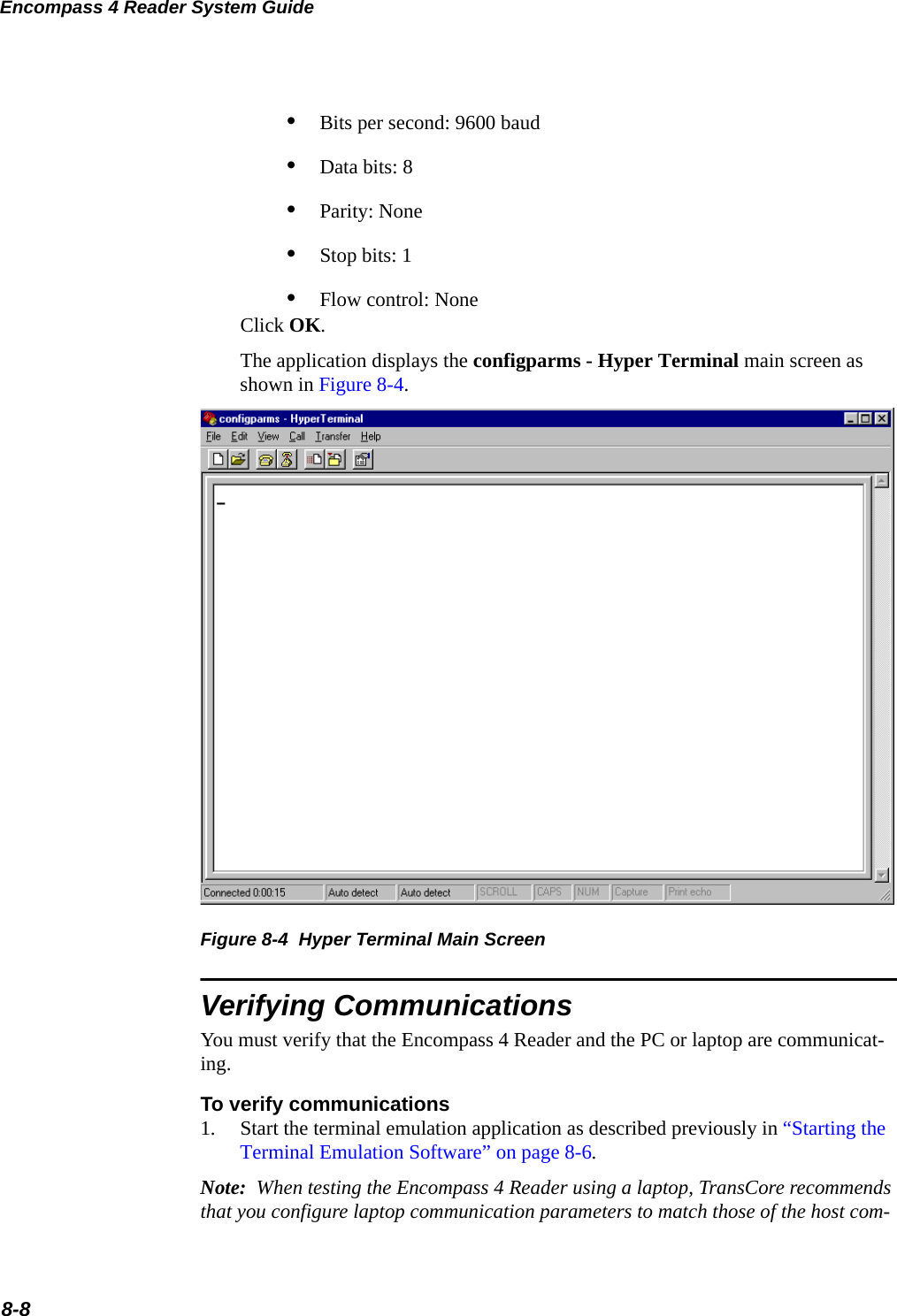
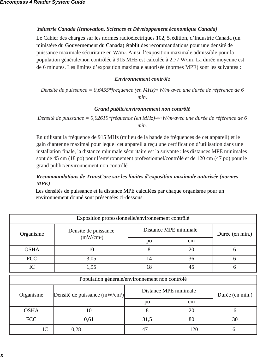
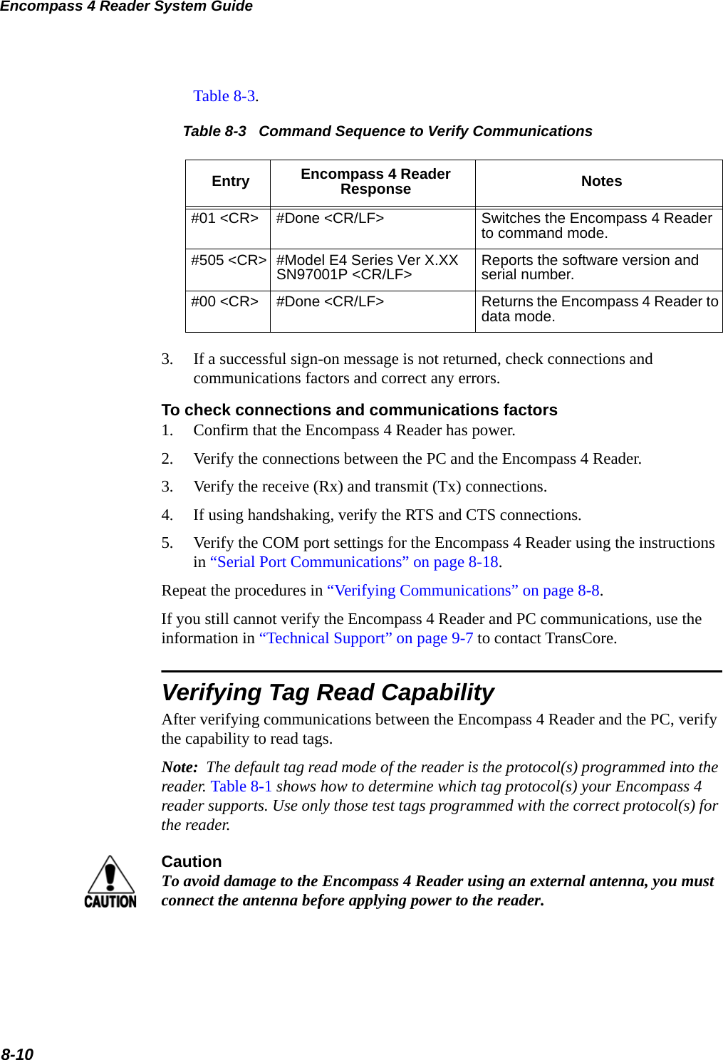
![Configuring the Encompass 4 Reader8-9puter to which the Encompass 4 Reader will be connected after testing and configura-tion are completed.2. Cycle the power on the Encompass 4 Reader.Upon startup, the Encompass 4 Reader transmits a sign-on message, displayed on the terminal emulation screen as shown in Figure 8-5, or a boot ROM failure message.Figure 8-5 Sign-on MessageThe sign-on message appears as follows: Model [software version] SNYYYYYY[Copyright notice]where YYYYYY is the serial number assigned to the Encompass 4 Reader skipping the fourth character printed on the reader product label.Serial number 000000 is the default setting and is not a valid number. If this number appears in the sign-on message, the serial number has never been stored into reader memory. Contact TransCore Technical Support.If the flash memory checksum is not verifiable, the sign-on message appears as follows:Model [E4 BOOT] Ver 0.00 A[Copyright notice]If the failure message version number equals 0.00 E and no serial number exists, the flash memory checksum has failed, and the Encompass 4 Reader is operating out of boot ROM. In this case, the Encompass 4 Reader automatically enters download mode and waits for a new program to be loaded into the flash memory. Follow the instructions in “Program Download” on page 5-5.Communications can also be verified by using the command sequence in ](https://usermanual.wiki/TransCore/0596465PT90/User-Guide-3159238-Page-215.png)


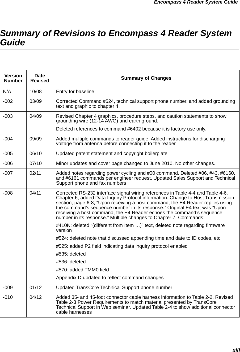
![Encompass 4 Reader System Guide9-6aUse this number to reference the problem you are having with the Encompass 4 Reader if you contact Transcore for Technical Support. 8When connected to a PC that is running terminal communications software, a just-powered up Encompass 4 Reader displays one of the following messages: #Model E4 Series X.XX SNYYYYYY#[Copyright notice]The Encompass 4 Reader works. The software is now loaded. YYYYYY is the TransCore-assigned serial number for this Encompass 4 Reader. However, if YYYYYY = 000000, a serial number has never been assigned. If a serial number has not been assigned to your Encompass 4 Reader, contact TransCore Technical Support.9The read zone is too small, even before the RF power and range control have been adjusted.If another Encompass 4 Reader is in the same area, ensure that it is operating on another frequency that is at least 2 MHz different.Check for possible interference from another nearby RF source: fluorescent lights, neon signs, high voltage power lines, nearby cellular telephone, or radio stations. Lights will need to be removed or shielded. Point the Encompass 4 Reader or external antenna in a different direction to see if interference comes from only one direction. You may require a different Encompass 4 Reader that uses another frequency.Verify that the RF power is set to an appropriate value.Verify that the range adjustment is set to the maximum.Verify that the reader is getting at least 16V. 10 The perimeter of the read zone has been defined, but there is a “hollow” spot in the center of the zone that does not read tags.The angle of the Encompass 4 Reader or external antenna may need adjustment. Slightly tilt the Encompass 4 Reader or external antenna to a different angle to change either the length or width of the read zone.Check the range control adjustment. See “Radio Frequency” on page 8-15. 11 The Encompass 4 Reader is reading tags out of the desired read zone, or cross-lane reads are occurring.Some interference from other RF or electrical sources may be occurring. See “Reflection, Refraction, and Diffraction of RF Signals” on page 2-16. Verify that the read zone has been properly set up. See “Fine-Tuning and Verifying the Read Zone” on page 8-19.12 The Encompass 4 Reader is not providing any output to the Wiegand interface.Ensure that the Encompass 4 Reader is in Wiegand mode (#451). The default is either RS–232 or RS–422 mode. Refer to “Wiegand Interface” on page 4-33. Ensure the tags are properly programmed with Wiegand data.Table 9-2 Symptoms and Remedies (continued)Symptom NumberaSymptom Remedy](https://usermanual.wiki/TransCore/0596465PT90/User-Guide-3159238-Page-234.png)


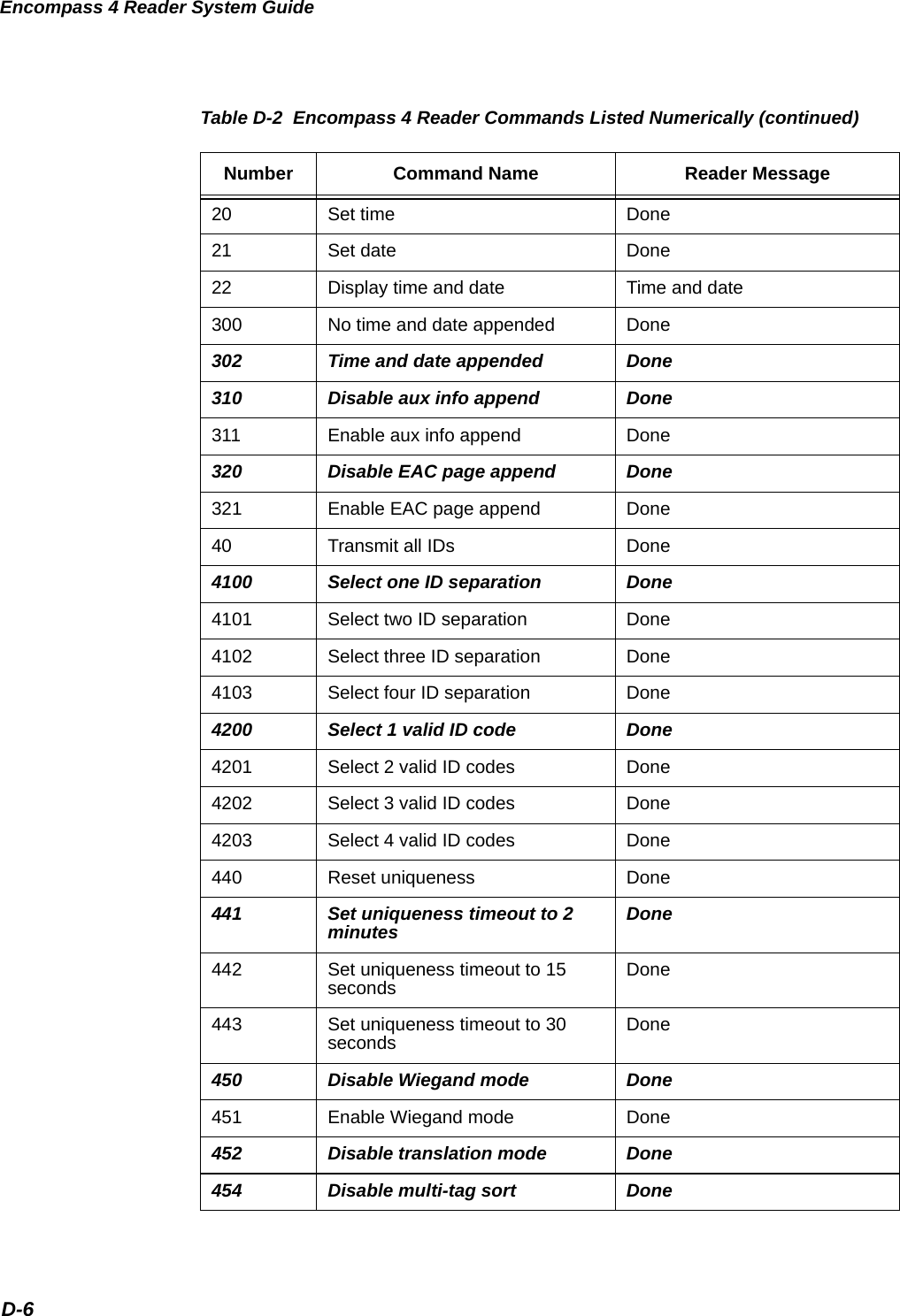
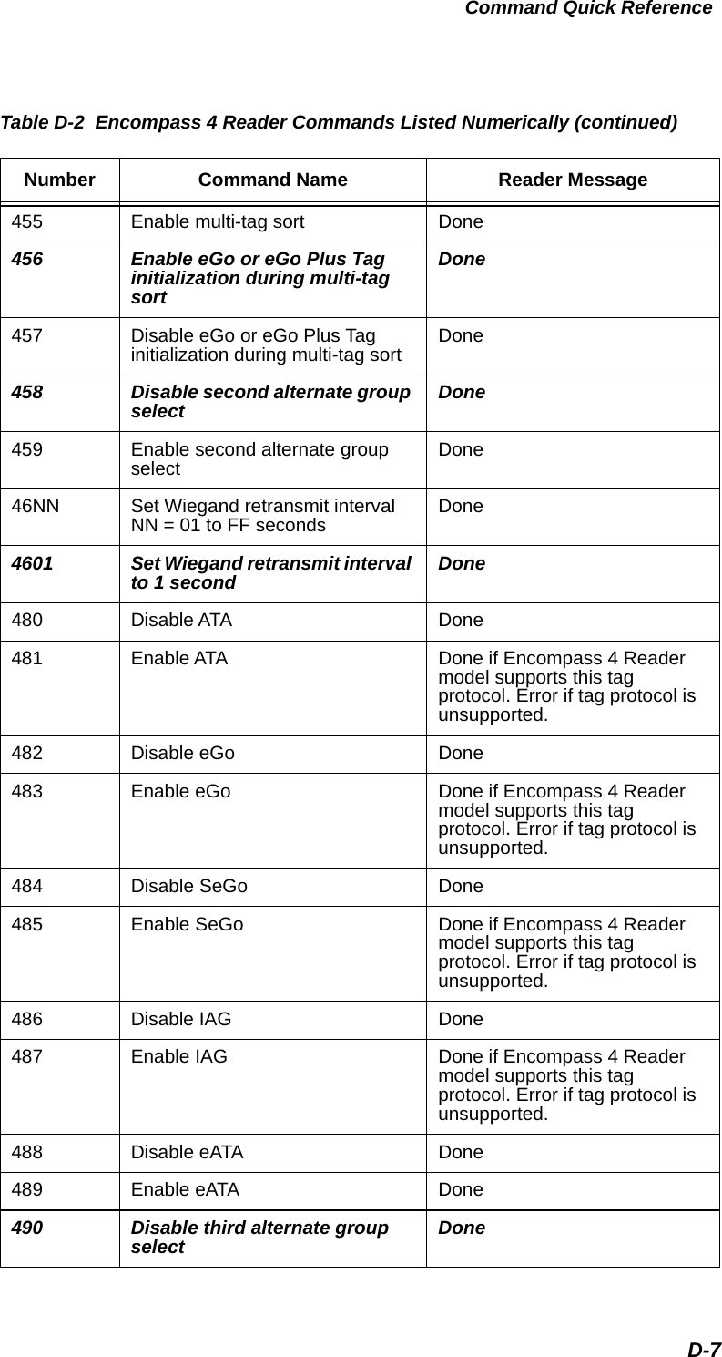
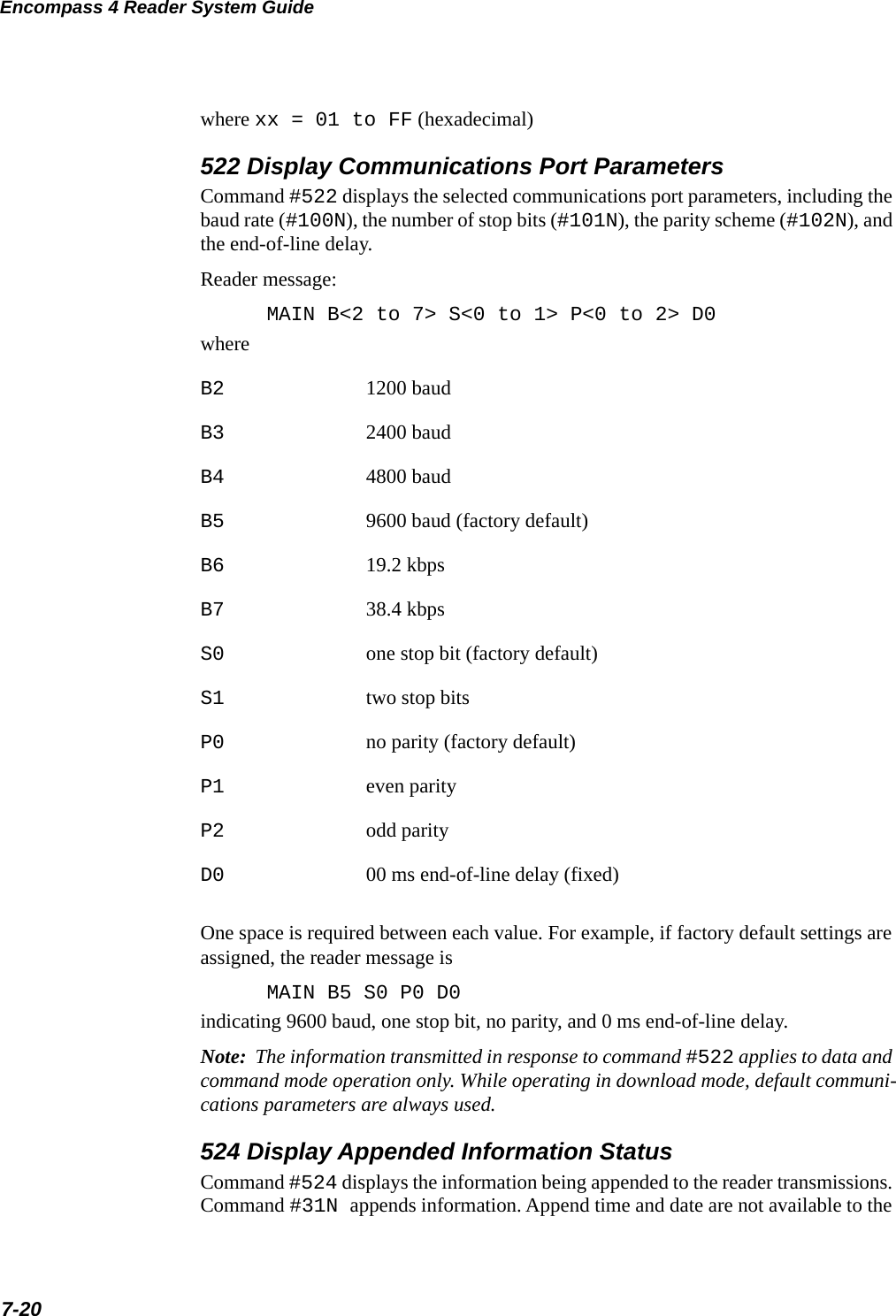
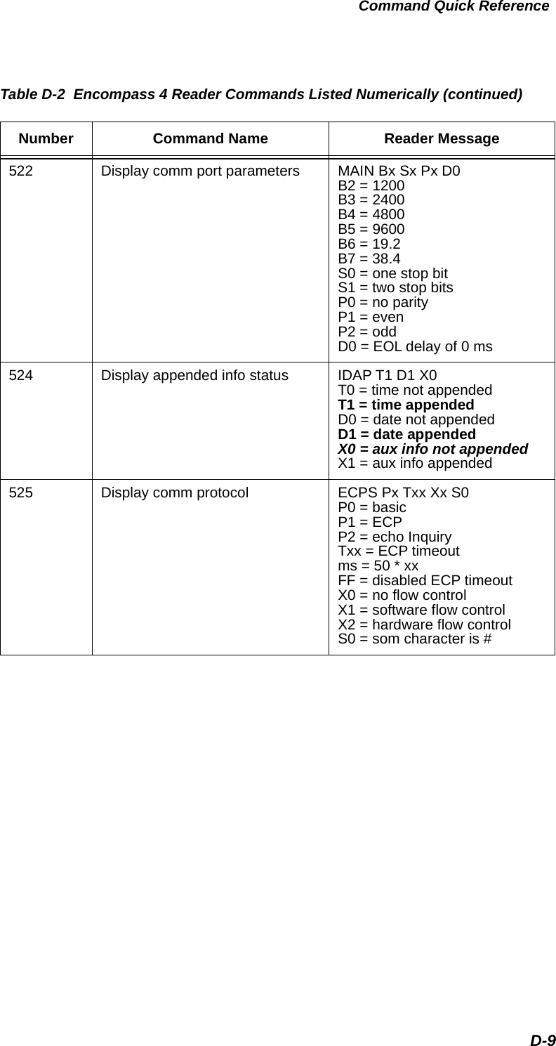
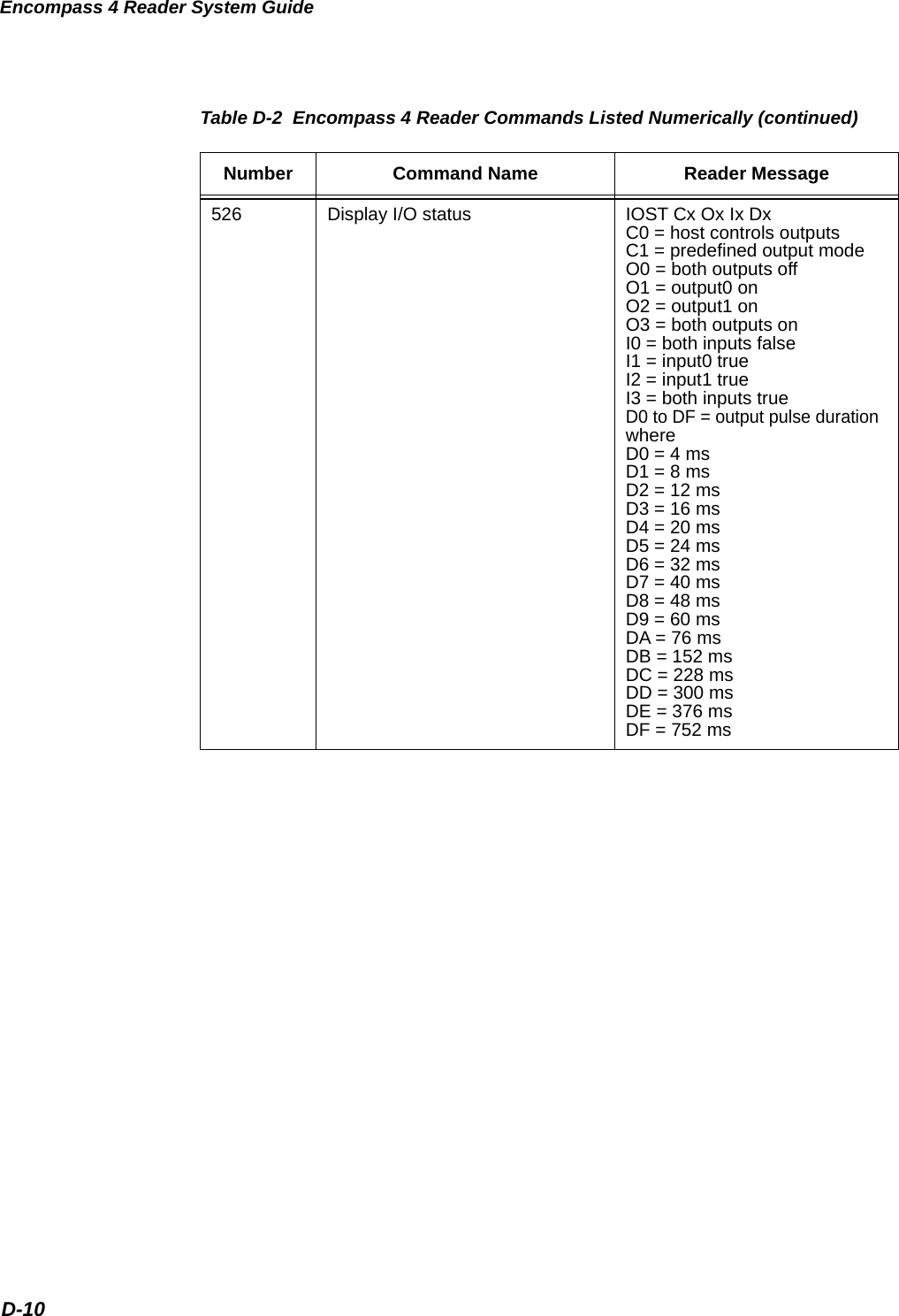
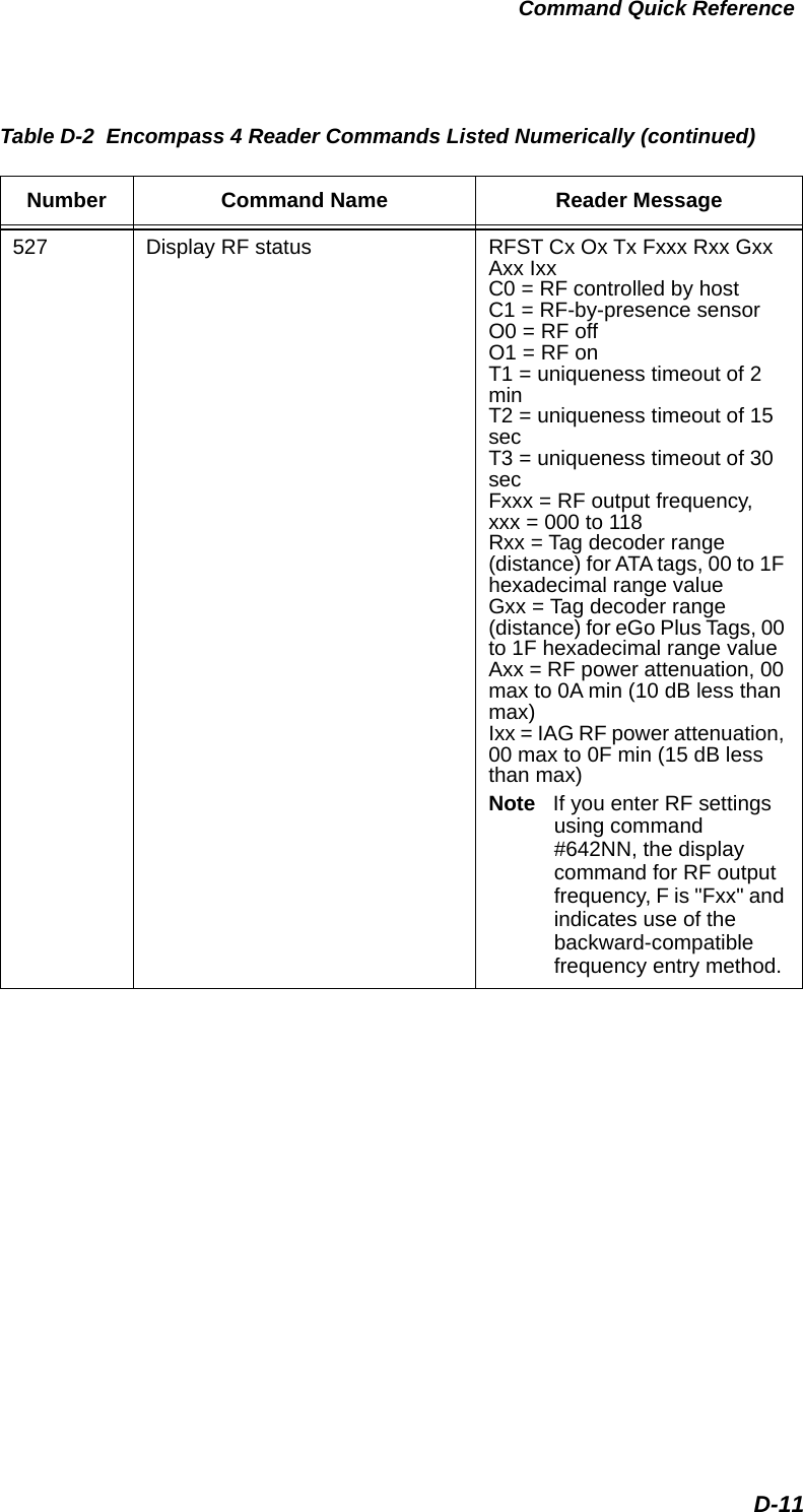
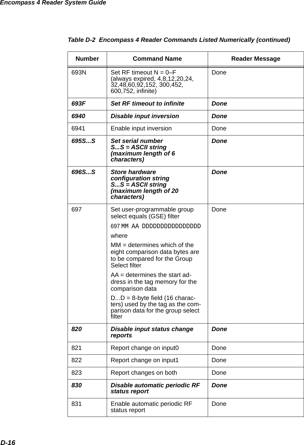
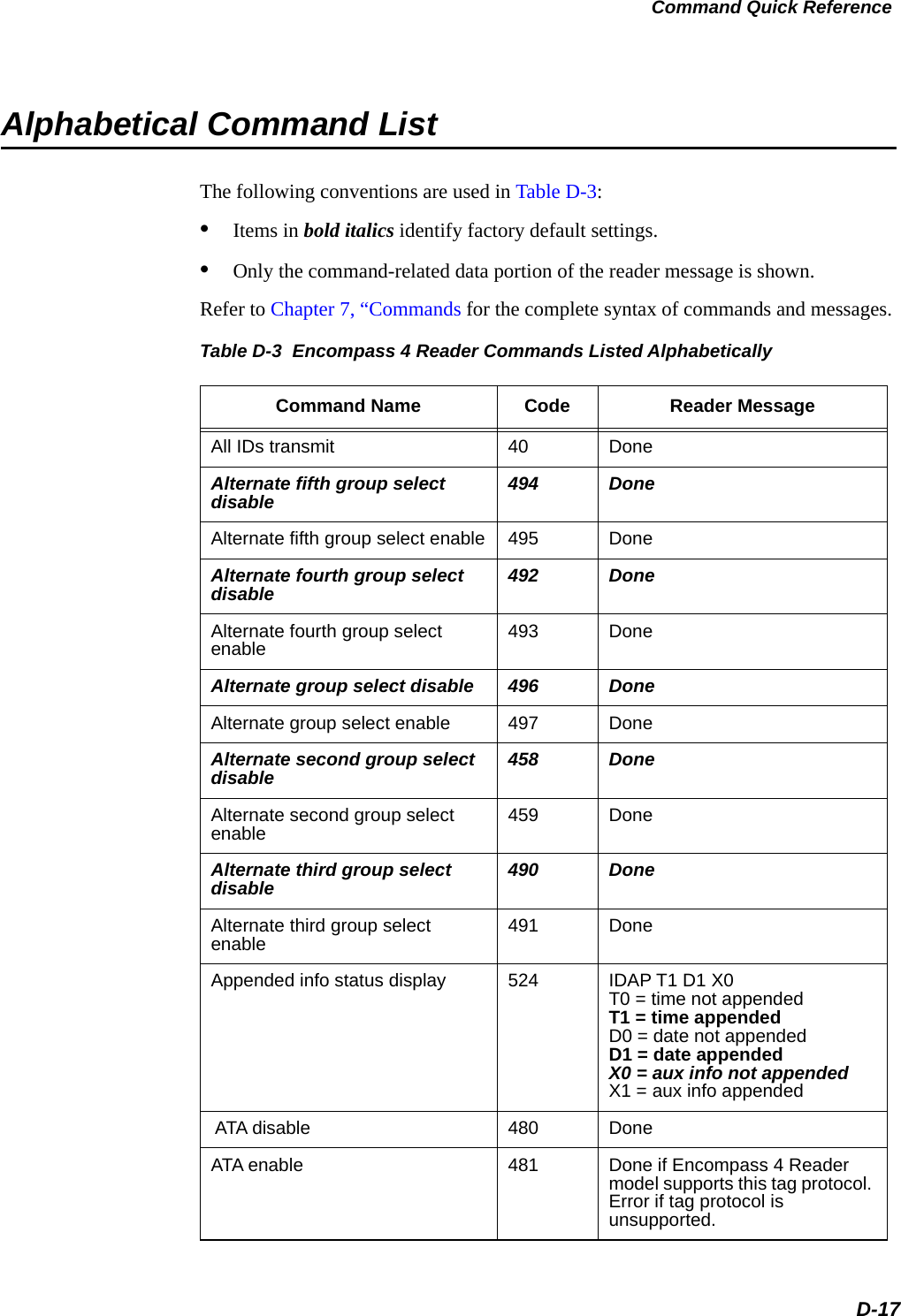
![Encompass 4 Reader System GuideD-8491 Enable third alternate group select Done 492 Disable fourth alternate group select Done493 Enable fourth alternate group select Done 494 Disable fifth alternate group select Done495 Enable fifth alternate group select Done 496 Disable alternate group select Done497 Enable alternate group select Done505 Display version Model [model] Ver [version no.] SN [serial no.]506 Display hardware configuration information S...S S...S = ASCII string(maximum length of 20 characters)510 Display RF transceiver FPGA version RF FPGA VER = XX.XX511 Display RF transceiver I filter chip version FIL IC I VER = XX.XX512 Display RF transceiver Q filter chip version FIL IC Q VER = XX.XX513 Display DSP board Actel version DSP FPGA VER = XX.XX520 Display power fail bit PWRB Px R0 P0 = no power fail has occurredP1 = power fail has occurredR0 = not applicable521 Display reader ID number RDID xx xx = 00–FFTable D-2 Encompass 4 Reader Commands Listed Numerically (continued)Number Command Name Reader Message](https://usermanual.wiki/TransCore/0596465PT90/User-Guide-3159238-Page-272.png)
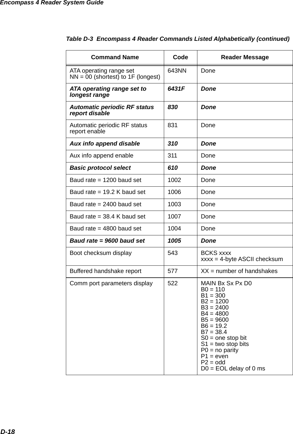
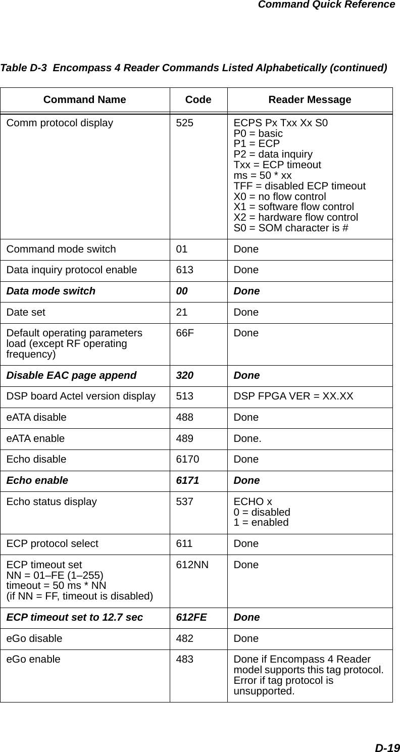
![Encompass 4 Reader System GuideD-14612NN Set ECP timeoutNN = 01–FE (1–255)timeout = 50 ms * NN(if NN = FF, timeout is disabled)Done 612FE Set ECP timeout = 12.7 sec Done 613 Enable data inquiry protocol Done6140 Disable flow control Done6141 Enable software flow control Done6142 Enable hardware flow control Done6170 Disable echo Done6171 Enable echo Done 6200 Turn both outputs off Done6201 Turn output0 on Done6202 Turn output1 on Done6203 Turn both outputs on Done621 Select predefined output mode Done63 Reset reader Model [model] Ver [version no.] SN [serial no.]Copyright [date]TransCore 6400 Turn off RF Done6401 Turn on RF Done641 Select RF-by-input control Done642NN Select RF operating frequency Done643NN Set ATA operating rangeNN = 00 (shortest) to 1F (longest) Done6431F Set ATA operating range to longest range Done644NN Set RF attenuation NN = 00 to 0A Done64400 Set RF attenuation to 0 dB (full power) DoneTable D-2 Encompass 4 Reader Commands Listed Numerically (continued)Number Command Name Reader Message](https://usermanual.wiki/TransCore/0596465PT90/User-Guide-3159238-Page-278.png)
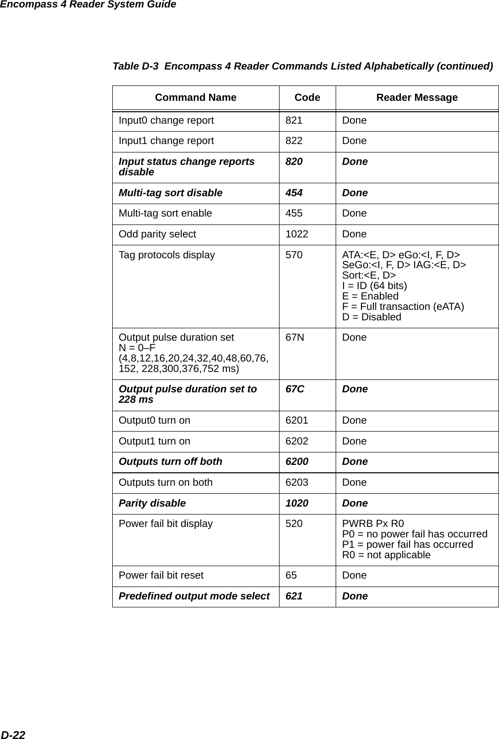
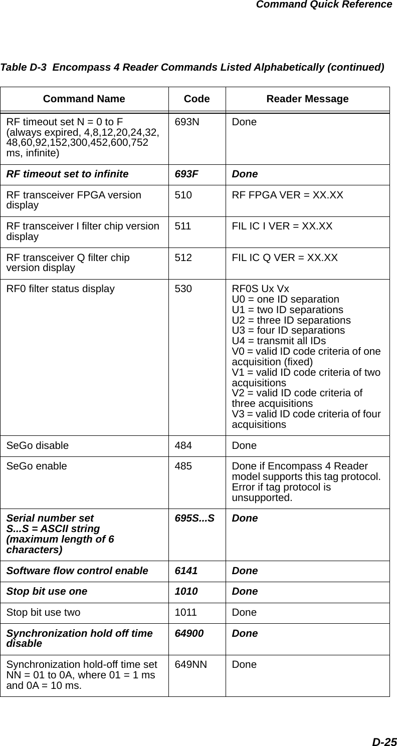
![Command Quick ReferenceD-23Presence input status display 529 PRST Px D0 Ax Tx IxP0 = disable presence w/o tag reportsP1 = enable presence w/o tag reportsD0 = min presence true period of 0 msA0 = RF off on timeoutA1 = RF off on timeout or tagA2 = RF off on timeout or no presenceT0: RF timeout of 0 ms (always expired)T1: RF timeout of 4 msT2: RF timeout of 8 msT3: RF timeout of 12 msT4: RF timeout of 20 msT5: RF timeout of 24 msT6: RF timeout of 32 msT7: RF timeout of 48 msT8: RF timeout of 60 msT9: RF timeout of 92 msTA: RF timeout of 152 msTB: RF timeout of 300 msTC: RF timeout of 452 msTD: RF timeout of 600 msTE: RF timeout of 752 msTF: RF timeout infinite, never expires (factory default)I0 = Input inversion disabled (factory default)I1 = Input inversion enabledPresence without tag reports disable 6900 DonePresence without tag reports enable 6901 DoneReader ID number display 521 RDID xx xx = 00–FFReader ID number setNN = 00 to FF 60NN DoneReader ID number set to 00 6000 DoneReader reset 63 Model [model] Ver [version no.] SN [serial no.]Copyright [date]TransCore Report changes both 823 DoneRF attenuation set NN = 00 to 0A 644NN Done Table D-3 Encompass 4 Reader Commands Listed Alphabetically (continued)Command Name Code Reader Message](https://usermanual.wiki/TransCore/0596465PT90/User-Guide-3159238-Page-287.png)
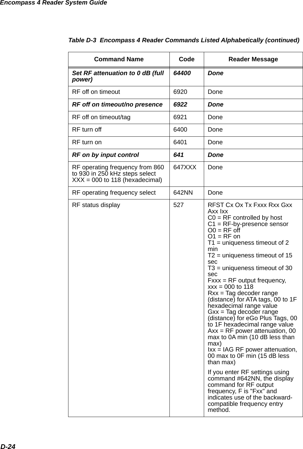
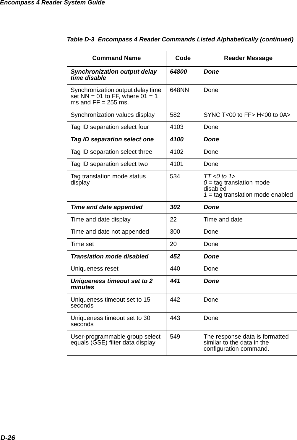
![Command Quick ReferenceD-27User-programmable group se-lect equals (GSE) filter set697 MM AA DDDDDDDDDDDDDDDDwhereMM = determines which of the eight comparison data bytes are to be compared for the Group Select filterAA = determines the start ad-dress in the tag memory for the comparison dataD...D = 8-byte field (16 charac-ters) used by the tag as the com-parison data for the group select filter697 DoneValid ID code select four 4203 DoneValid ID code select one 4200 DoneValid ID code select three 4202 DoneValid ID code select two 4201 DoneVersion display 505 Model [model] Ver [ver no.] SN [serial no.]Wiegand mode disable 450 DoneWiegand mode enable 451 DoneWiegand mode status display 532 T0F x0 = disabled1 = enabledWiegand retransmit interval display 533 WTI xx xx = 01–FF secondsWiegand retransmit interval setNN = 01 to FF seconds 46NN Done Wiegand retransmit interval set to 1 second 4601 DoneTable D-3 Encompass 4 Reader Commands Listed Alphabetically (continued)Command Name Code Reader Message](https://usermanual.wiki/TransCore/0596465PT90/User-Guide-3159238-Page-291.png)