TransCore 05986 Location Monitoring Services Transmitter User Manual
TransCore Location Monitoring Services Transmitter
User Manual
Trusted Transportation Solutions
GoAnywhere Pass™
RUNNER
Installation Instructions
16-0092-001 Rev A 06/17
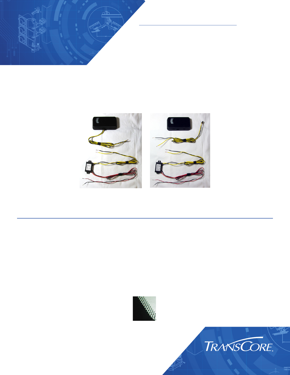
The GoAnywhere Pass Runner is an interior-mounted transponder that
is powered directly from the vehicle through a wire harness assembly
connected to switched power at the vehicle’s fuse panel. This product is
available in a hard-wired model or with a connector cable.
Transponder Instructions and Guidelines
Metallized Windshield
Some vehicle windshields contain a metallic treatment that could prevent an interior windshield-
mounted device from working correctly. If you have a vehicle with a metalized windshield, contact
your local customer service center for more information.
Windshield Band
Some windshields have a solid or dotted black frit band around the edges of the windshield
(Figure 1). The frit band protects the windshield mounting materials from the sun and ultra-violet
rays. The Runner transponder may be placed behind this band if necessary without aecting
performance.
Figure 1 – Windshield Frit Band
Hard-wired Connector Cable
Installation Instructions
Page 2
Runner Transponder Installation
Required Supplies
• Runner Transponder
• Commercial glass cleaner and paper towels
Determine Transponder Location
The Runner transponder should be mounted on the interior windshield, with the longest side
parallel to the bottom of the windshield. Other tags should be kept at least 3 inches away from
the transponder. The area on the dashboard beneath the transponder must be kept clear of
paperwork and metallic items.
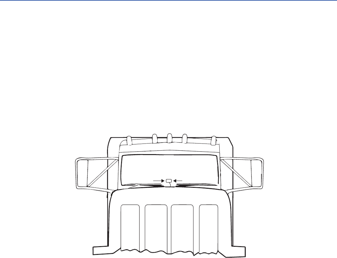
1. If the vehicle has a one-piece windshield, the Runner transponder should be centered
on the windshield, 3 inches above the dashboard (Figure 2).
Figure 2 – Placement of Runner on one-piece windshield
TA-0480
Centered, 3” from
bottom of windshield
Page 3
Runner
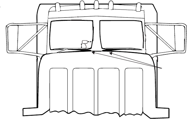
2. If the vehicle has a two piece windshield, the Runner transponder should be mounted
on the passenger side, 3 inches away from the center dividing bar and 4 inches above
the dashboard (Figure 3).
Figure 3 – Placement of Runner on two-piece windshield
3. Clean and dry the interior windshield surface completely. The windshield temperature
must be at least 68ºF (20ºC) for optimum bonding.
4. Peel the backing o of the transponder to expose adhesive. Apply the Runner
transponder to the windshield using moderate pressure.
Note: Installation is semi-permanent and the transponder cannot be moved once it is in
place
Windshield
Wipers
TA-0479
4”
3”
Installation Instructions
Page 4
Standard Wiring Instructions
Runner is powered directly from the vehicle through a power harness assembly connected to
switched power at the vehicle’s fuse panel. To complete the installation of the Runner transponder,
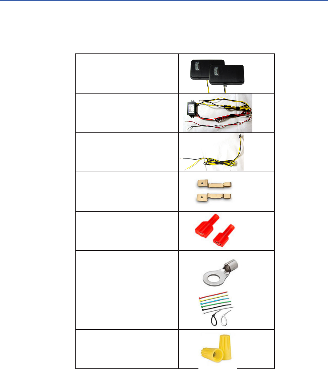
be sure that you have the parts listed in Table 1.
Table 1 – Parts List
Runner Transponder,
hard-wired or with connector
Runner Power Harness
Power Cable with Connector
(Optional)
Fuse Taps
Quick Disconnects for 20 AWG
wire
Ring Terminals for 20 AWG wire
Zip Ties
Wire Nuts for 20 AWG wire
Page 5
Runner
You may also need these tools in order to complete the installation:
• Needle nose pliers
• Screwdriver set
• Socket set
• Voltage meter
• Wire crimper
• Wire snips
• Wire strippers
Assemble the Power Cable and Harness
Note: Connection to the power harness assembly will be located underneath the
dashboard of your vehicle.
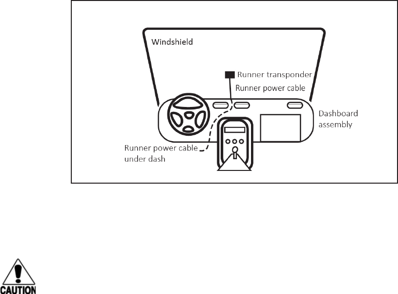
1. Run the Runner power cable through the gap between the bottom of the windshield
and the dashboard assembly (Figure 4).
Note: If you are using the optional Connectorized Power Cable, connect the cable to
the Runner transponder before beginning Step 2.
Figure 4 – Run power cable behind the dashboard assembly
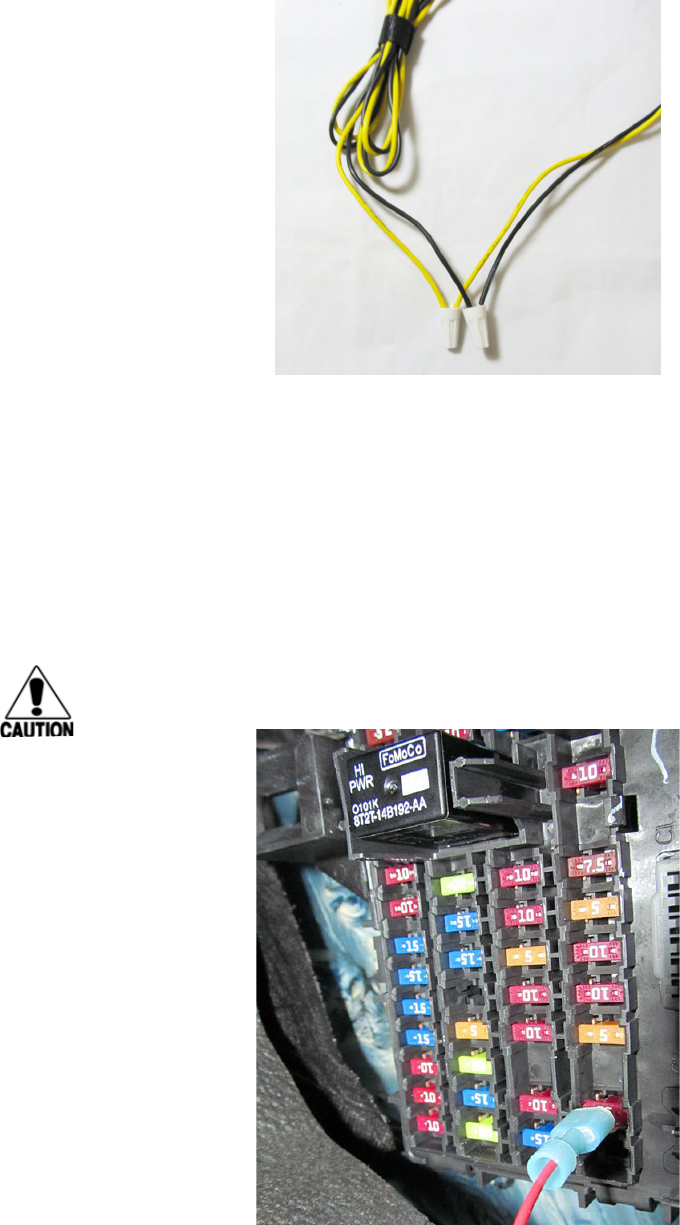
2. Connect the Runner power cable to the Runner power harness. Use wire nuts and
match black wires to black wires and yellow wires to yellow wires (Figure 5).
Caution:
Do not power the Runner transponder directly from 12/24 ADC. You must use the
power harness assembly.
Installation Instructions
Page 6
Figure 5 – Connect Runner cable to harness assembly
Connect Cable to Vehicle Power
1. Locat a fuse (max. 25 Amp) in the fuse panel that has voltage present ONLY when the
ignition switch is in the run/on position.
2. Remove the fuse. Using a voltage meter, determine which side of the fuse receptacle
DOES NOT have power when the ignitition switch is in the run/on position.
3. Attach the Red/Continuous power wire using a fuse tap and a quick disconnect of the
appropriate size, depending on fuse (Figure 6).
CAUTION: Do NOT place fuse taps on hot side of fuse.
Figure 6 – Fuse tap with quick disconnect
Page 7
Runner
4. Place fuse back into panel where it was removed. Make sure the fuse tap is on the side
of fuse receptacle that DOES NOT have power when the ignition switch is in the run/on
position.
5. Locate a ground attachment point. Find a bolt or nut that is attached to bare metal.
6. Secure the Black/Ground wire using the appropriate size ring terminal.
7. Zip ties may be used as needed to manage extra slack in the wiring assembly.
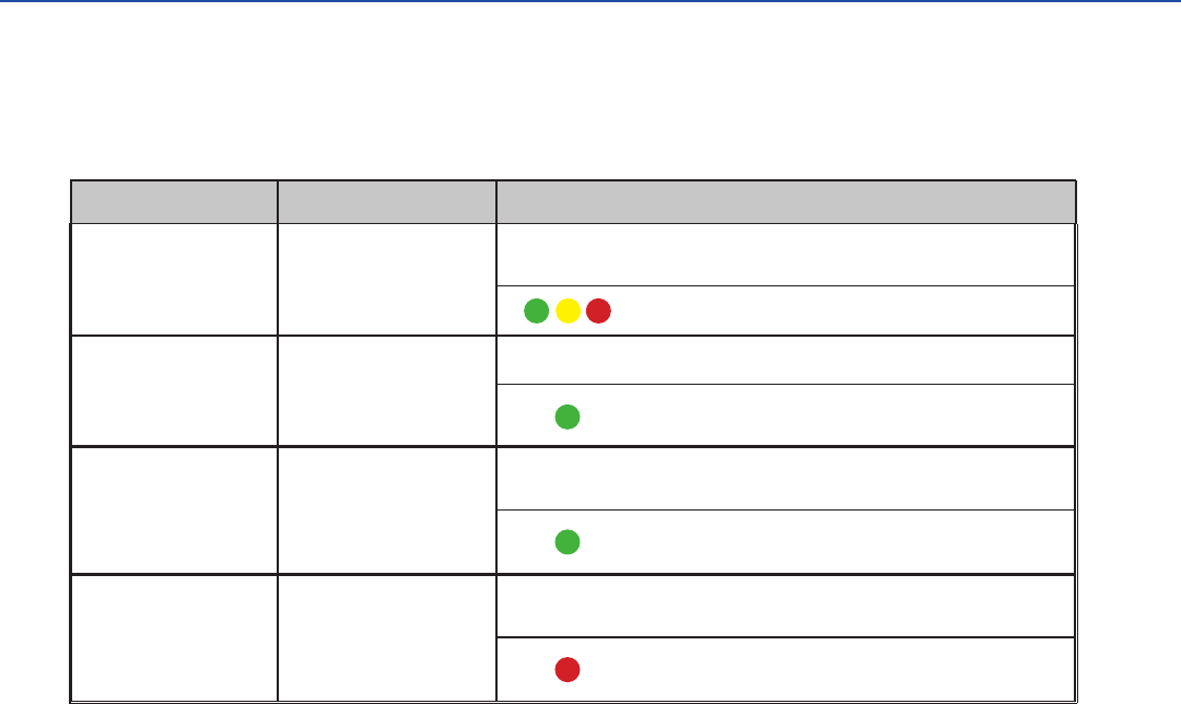
Audio/Visual Signals
Your Runner is equipped with audio/visual signals that will alert you about certain conditions
relevant to your tag. Refer to Table 2 for a list of audio and visual signals.
Table 2 – Runner Audio/Visual Signals
Notifi cation Indication Audio/Visual Signals
Ready to Go
Indicates tag is ready for
operation
x 4 Four quick beeps accompanied by visual signals
LEDs fl ash once in sequence, once together
Title 21 Acknowledge
(T21 Protocol Only)
Indicates a successful
transaction
Ocurs as the vehicle passes
through a Title-21 toll
installation
x 2 Two short beeps accompanied by visual signals
LED fl ashes 5 times
Weigh Station Bypass
(ASTM V6 Protocol Only)
Indicates that driver may
bypass the weigh station
Occurs just prior to a weigh
station off -ramp
x 9 Nine 2-second beeps, accompanied by visual signals
LED stays constant for 6 seconds, then displays 2 two
short fl ashes at 3 second intervals for 15 seconds. The LED
fl ashes every 10 seconds for 15 minutes
Weigh Station Pull-in
(ASTM V6 Protocol Only
Indicates that the driver
must pull into the weigh
station
Occurs just prior to a weigh
station off -ramp
x 18 Eighteen half-second beeps, accompanied by visual signals
LED stays constant for 6 seconds, then displays 2 two
short fl ashes at 3 second intervals for 15 seconds. The LED
fl ashes every 10 seconds for 15 minutes
Installation Instructions
Page 8
NO UNAUTHORIZED MODIFICATIONS STATEMENT
Caution: This equipment may not be modied, altered, or changed in any way without permission from
TransCore, LP. Unauthorized modication may void the equipment authorization from the FCC and will
void the TransCore warranty.
RADIO FREQUENCY INTERFERENCE STATEMENTS
Note: This device complies with Part 15 of the FCC Rules and the Industry Canada Licence-Exempt RSS
Standards. Operation is subject to the following two conditions:
(1) this device may not cause interference, and
(2) this device must accept any interference, including interference that may cause undesired operation of
this device.
Note: Le présent appareil est conforme aux CNR d’Industrie Canada applicables aux appareils radio
exempts de licence. L’exploitation est autorisée aux deux conditions suivantes:
(1) l’appareil ne doit pas produire de brouillage, et
(2) l’utilisateur del’appareil doit accepter tout brouillage radioélectrique subi, même si le brouillage est
susceptible d’en compromettre le fonctionnement.
Page 9
Runner

For more information:
Sales Support
800.923.4824
Technical Support
505.856.8007
transcore.com
Trusted Transportation Solutions
© 2017 TransCore L.P. All rights reserved. TRANSCORE is a registered trademark, and
is used under license. All other trademarks listed are the property of their respective
owners. Contents subject to change. Printed in the U.S.A.