TransCore AI142205618 LMS TRANSMITTER User Manual 411237 002 AI1422 RDR UG
TransCore LMS TRANSMITTER 411237 002 AI1422 RDR UG
USERS MANUAL

AI1422 Half-Frame Reader
User Guide
TransCore, Inc.
19111 Dallas Parkway, Suite 300
Dallas, Texas 75287-3106
October 2004
P/N 411237-003
©2004 TC IP, Ltd. All rights reserved. TRANSCORE is a registered trademark. The trademark is used under
license. All other trademarks listed are the property of their respective owners. Contents are subject to change.
Printed in the U.S.A.
Products covered by this document are protected by one or more of the following U.S. patents 4,739,328;
4,864,158; 4,999,636; and foreign equivalent patents. Other patents pending.
For further information, contact:
TransCore
19111 Dallas Parkway, Suite 300
Dallas, Texas 75287-3106 USA
Phone: (972) 733-6600
Fax: (972) 733-6699
TransCore Action Center (TrAC)
19111 Dallas Parkway, Suite 300
Dallas, Texas 75287-3106 USA
Phone: (800) 755-0378
Fax: (972) 733-6695
WARNING TO USERS IN THE UNITED STATES
FEDERAL COMMUNICATIONS COMMISSION (FCC) RADIO FREQUENCY
INTERFERENCE STATEMENT
47 CFR §15.105(a)
NOTE: This equipment has been tested and found to comply with the limits for a Class A digital device
pursuant to Part 15 of the Federal Communications Commission (FCC) rules. These limits are designed to
provide reasonable protection against harmful interference when the equipment is operated in a
commercial environment. This equipment generates, uses, and can radiate radio frequency (RF) energy and
may cause harmful interference to radio communications if not installed and used in accordance with the
instruction manual. Operating this equipment in a residential area is likely to cause harmful interference, in
which case, depending on the laws in effect, the users may be required to correct the interference at their
own expense.
NO UNAUTHORIZED MODIFICATIONS
47 CFR §15.21
CAUTION: This equipment may not be modified, altered, or changed in any way without permission
from TransCore, Inc. Unauthorized modification may void the equipment authorization from the FCC and
will void the TransCore warranty.
USE OF SHIELDED CABLES IS REQUIRED
47 CFR §15.27(a)
Shielded cables must be used with this equipment to comply with FCC regulations.
A license issued by the FCC is required to operate this RF identification device in the United States.
Contact TransCore, Inc. for additional information concerning licensing requirements for specific devices.
TransCore, Inc.
USA


vii
Contents
1 Before You Begin
Purpose of This Guide. . . . . . . . . . . . . . . . . . . . . . . . . . . . . . . . . . . . . . . . . . . . . 1-3
Intended Audience . . . . . . . . . . . . . . . . . . . . . . . . . . . . . . . . . . . . . . . . . . . . . . . . 1-3
Related Documents . . . . . . . . . . . . . . . . . . . . . . . . . . . . . . . . . . . . . . . . . . . . . . . 1-3
Guide Topics . . . . . . . . . . . . . . . . . . . . . . . . . . . . . . . . . . . . . . . . . . . . . . . . . . . . 1-3
Typographical Conventions . . . . . . . . . . . . . . . . . . . . . . . . . . . . . . . . . . . . . . . . 1-4
2 System Overview
System Overview . . . . . . . . . . . . . . . . . . . . . . . . . . . . . . . . . . . . . . . . . . . . . . . . . 2-3
Transponder Interrogator . . . . . . . . . . . . . . . . . . . . . . . . . . . . . . . . . . . . . . . . . . 2-3
Reader Power Regulation and Filtering. . . . . . . . . . . . . . . . . . . . . . . . . . . . . . . 2-4
Antenna . . . . . . . . . . . . . . . . . . . . . . . . . . . . . . . . . . . . . . . . . . . . . . . . . . . . . . . 2-4
Transponders (Tags) . . . . . . . . . . . . . . . . . . . . . . . . . . . . . . . . . . . . . . . . . . . . . 2-4
3 Interface Connections
Description of AI1422 Reader System . . . . . . . . . . . . . . . . . . . . . . . . . . . . . . . . 3-3
Antenna Interface. . . . . . . . . . . . . . . . . . . . . . . . . . . . . . . . . . . . . . . . . . . . . . . . . 3-3
Main RS–232 Interface . . . . . . . . . . . . . . . . . . . . . . . . . . . . . . . . . . . . . . . . . . . . . 3-3
Aux RS–232 Interface . . . . . . . . . . . . . . . . . . . . . . . . . . . . . . . . . . . . . . . . . . . . . 3-4
Customer I/O Interface. . . . . . . . . . . . . . . . . . . . . . . . . . . . . . . . . . . . . . . . . . . . . 3-4
Lock LED. . . . . . . . . . . . . . . . . . . . . . . . . . . . . . . . . . . . . . . . . . . . . . . . . . . . . . 3-5
Main Power LED . . . . . . . . . . . . . . . . . . . . . . . . . . . . . . . . . . . . . . . . . . . . . . . . 3-5
RF Power LED. . . . . . . . . . . . . . . . . . . . . . . . . . . . . . . . . . . . . . . . . . . . . . . . . . 3-5
Trigger Signals . . . . . . . . . . . . . . . . . . . . . . . . . . . . . . . . . . . . . . . . . . . . . . . . . 3-5
Channels A, B, and C . . . . . . . . . . . . . . . . . . . . . . . . . . . . . . . . . . . . . . . . . . . . 3-6
Power Connection . . . . . . . . . . . . . . . . . . . . . . . . . . . . . . . . . . . . . . . . . . . . . . . 3-6

AI1422 Half-Frame Reader System User Guide
viii
4 System Test Procedures
Required Tools and Equipment . . . . . . . . . . . . . . . . . . . . . . . . . . . . . . . . . . . . . 4-3
Testing Basic Operation . . . . . . . . . . . . . . . . . . . . . . . . . . . . . . . . . . . . . . . . . . . 4-3
Measuring RF Power . . . . . . . . . . . . . . . . . . . . . . . . . . . . . . . . . . . . . . . . . . . . . . 4-5
Measuring System Noise. . . . . . . . . . . . . . . . . . . . . . . . . . . . . . . . . . . . . . . . . . . 4-6
Reading the Tag . . . . . . . . . . . . . . . . . . . . . . . . . . . . . . . . . . . . . . . . . . . . . . . . . . 4-8
5 Command Codes
Default Command Codes . . . . . . . . . . . . . . . . . . . . . . . . . . . . . . . . . . . . . . . . . . 5-3
Asynchronous Reader Data Telegram . . . . . . . . . . . . . . . . . . . . . . . . . . . . . . . 5-3
Health Status Request . . . . . . . . . . . . . . . . . . . . . . . . . . . . . . . . . . . . . . . . . . . 5-3
Retransmit Request. . . . . . . . . . . . . . . . . . . . . . . . . . . . . . . . . . . . . . . . . . . . . . 5-3
Diagnostic Command Codes . . . . . . . . . . . . . . . . . . . . . . . . . . . . . . . . . . . . . . . 5-4
Diagnostic Command Code Syntax . . . . . . . . . . . . . . . . . . . . . . . . . . . . . . . . . 5-4
Diagnostic Command Code Listing . . . . . . . . . . . . . . . . . . . . . . . . . . . . . . . . . . 5-4
6 Troubleshooting
Required Tools and Equipment . . . . . . . . . . . . . . . . . . . . . . . . . . . . . . . . . . . . . 6-3
Troubleshooting. . . . . . . . . . . . . . . . . . . . . . . . . . . . . . . . . . . . . . . . . . . . . . . . . . 6-3
Failure Modes . . . . . . . . . . . . . . . . . . . . . . . . . . . . . . . . . . . . . . . . . . . . . . . . . . 6-3
Unit Will Not Read Tags . . . . . . . . . . . . . . . . . . . . . . . . . . . . . . . . . . . . . . . . . . 6-4
Unit Will Not Retain Settings . . . . . . . . . . . . . . . . . . . . . . . . . . . . . . . . . . . . . . . 6-4
Maintenance Procedures. . . . . . . . . . . . . . . . . . . . . . . . . . . . . . . . . . . . . . . . . . . 6-4
A Character Conversion
B Technical Specifications
C Diagnostic Command Codes List

Contents
ix
List of Figures
Figure 2-1 Typical Reader System Configuration 2-3
Figure 3-1 Front Panel of AI1422 Transponder Interrogator 3-3
Figure 3-2 RS–232, DB25 Interface Connector Pin-outs . . . . . . . . . . . . . . . . . . . . . . . . . . . . 3-4
Figure 3-3 Customer I/O Interface Pin-outs . . . . . . . . . . . . . . . . . . . . . . . . . . . . . . . . . . . . . 3-5
Figure 4-1 Power Source Connections 4-4
Figure 4-2 Locations for DC Voltage Adjustment Measuring RF Power . . . . . . . . . . . . . . . . . . 4-5
Figure 4-3 Antenna Interface on Front Panel . . . . . . . . . . . . . . . . . . . . . . . . . . . . . . . . . . . . 4-5
Figure 4-4 Typical Waveform with a Tag in the Reader Field . . . . . . . . . . . . . . . . . . . . . . . . . 4-7
Figure 4-5 Typical Quiescent Noise Waveform . . . . . . . . . . . . . . . . . . . . . . . . . . . . . . . . . . 4-7
Figure 4-6 Typical Beat Frequency Interference Waveform . . . . . . . . . . . . . . . . . . . . . . . . . . 4-8
List of Tables
Table 1-2 Typographical Conventions . . . . . . . . . . . . . . . . . . . . . . . . . . . . . . . . . . . . . . . . 1-4
Table 4-1 System Noise Test Parameters . . . . . . . . . . . . . . . . . . . . . . . . . . . . . . . . . . . . . . 4-6
Table A-1 TransCore 6-Bit-Per-Character Conversion . . . . . . . . . . . . . . . . . . . . . . . . . . . . . A-3
Table B-1 AI1422 Half-Frame Reader System Specifications . . . . . . . . . . . . . . . . . . . . . . . . . B-3
AI1422 Half-Frame Reader System User Guide
x

1
Before You Begin

1-3
Chapter 1
Before You Begin
The AI1422 Half-Frame Reader User Guide provides information
necessary for interfacing the AI1422 Half-Frame Reader System to a host
computer system.
Purpose of This Guide
This user guide provides information for interfacing the AI1422 Half-Frame Reader
System with a host processor system, also called a host computer system. This guide
also provides on-site test procedures useful in troubleshooting any problems
encountered after installation. Command codes, which allow the user to configure the
reader system for communicating with the host computer, are discussed in Chapter 4.
The ASCII character conversion to TransCore 6-bit character codes is provided in
Appendix A.
Intended Audience
The intended audience for the AI1422 Half-Frame Reader User Guide is engineers
and technicians. These people are involved in the design, specification, and
installation of AI1422 Half-Frame Reader Systems.
Related Documents
AP4110 Programmer’s Guide
Guide Topics
This document presents the following information:
Chapter 1 – Before You
Begin
Describes the purpose, intended audience, guide topics, related
documentation, and document conventions.
Chapter 2 – AI1422 Half-
Frame Reader System
Overview
Provides an overview of the AI1422 Half-Frame Reader System’s features,
options, and accessories.
Chapter 3 – Interface
Connections
Describes the AI1422 Half-Frame Reader System interface connectors and
identifies their primary functions.
Chapter 4 – System Test
Procedures
Provides testing procedures that the user can use to fine-tune the AI1422
Half-Frame Reader System.
AI1422 Half-Frame Reader System User Guide
1-4
Typographical Conventions
Table 1-2 lists the conventions used in this manual.
Chapter 5 – Firmware
Command Codes
Discusses the firmware command code that are used to configure the AI1422
Reader for communication with a personal computer or other host computer.
Chapter 6 – Maintenance
and Troubleshooting
Provides maintenance procedures and troubleshooting indications that are
used to keep the AI1422 Half-Frame Reader System operating.
Appendix A – Character
Conversions
Provides TransCore 6-bit-per-character conversions from the standard ASCII
character set.
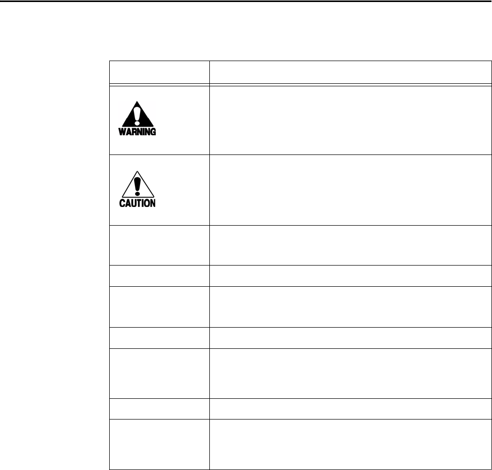
Table 1-2 Typographical Conventions
Convention Indication
This procedure might cause harm to the equipment and/or
the user.
Concerns about a procedure
Code Code, including keywords and variables within text and as
separate paragraphs, and user-defined program elements
within text appear in courier typeface.
Dialog Box Title Title of a dialog box as it appears on screen
Function Start with the characters, G4, and are in mixed case with no
underscores, and include parentheses after the name, as in
G4FunctionName().
Menu Item Appears on a menu. Capitalization follows the interface.
Note Auxiliary information that further clarifies the current
discussion. These important points require the user’s
attention. The paragraph is in italics and the word Note is
boldface.
NUL Zero-value ASCII character or a zero-value byte
NULL Zero-value pointers. Null-terminated string refers to strings
of printable ASCII characters with a zero-value byte placed
in memory directly after the last printable character of the
string.

2
System Overview
2-3
Chapter 2
System Overview
The AI1422 Half-Frame Reader System is a microprocessor-controlled,
single-antenna unit that uses a unique communications protocol to
interface with vehicle identification (ID) equipment.
System Overview
This reader system uses radio frequency (RF) energy to read data from tags. The
AI1422 Half-Frame Reader System then decodes the tag ID information, validates the
ID code, and transmits tag data directly to a host processor for real-time data process-
ing and use.
Communications (terminal) programs usually do not provide adequate data processing
capability. Your host computer software can be customized to provide the required
capabilities.
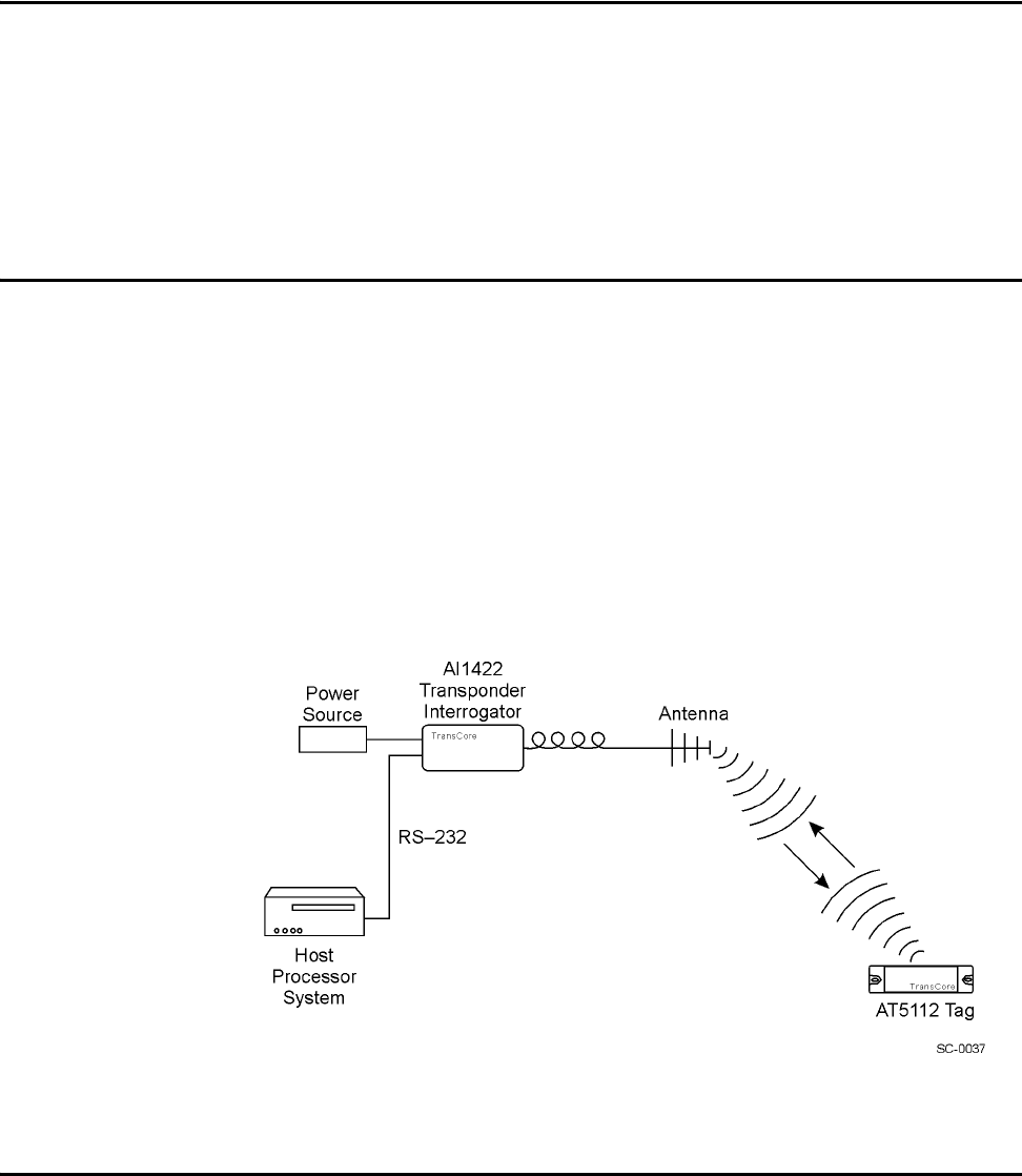
The AI1422 Half-Frame Reader System consists of the AI1422 Transponder Interro-
gator, which consists of a reader and RF module, combined with a TransCore antenna,
a TransCore tag, a host processor system, and a power source. Figure 2-1 illustrates a
typical reader system configuration.
Figure 2-1 Typical Reader System Configuration
Transponder Interrogator
The transponder interrogator reads 60 bits of user-programmable data in the transpon-
der.

AI1422 Half-Frame Reader System User Guide
2-4
The transponder interrogator is operated in a continuous read mode, and any tag enter-
ing its read field has its data automatically read and relayed to the host computer. In
many applications this function is implemented by installing the reader on a vehicle
with restricted movement, such as a railcar or monorail bus. The tags are imbedded in
the roadway at various locations in the vehicle’s path. The data read from the tag
allows the host computer to assess the vehicle’s location and make any appropriate
response to that information.
The transponder interrogator is an independent tag decoder that combines a reader and
RF source to provide automatic identification and data storage within a single,
compact unit. The transponder interrogator includes the following components:
•19-inch rack-mount design
•Serial input/output (I/O) link
•Real-time clock
•32K buffer storage in static random access memory (SRAM) with battery backup
•Reader and RF module, combined in one unit
Reader Power Regulation and Filtering
The reader system uses an input voltage ranging from 8V DC to 140V DC. The
AI1422 Reader System incorporates a high-performance, DC-to-DC power supply
that converts voltage in this range to 13.5V DC. TransCore offers three input voltage
options, 8V DC to 32V DC, 28V DC to 140V DC, and 14V DC to 70V DC.
Antenna
TransCore has two antennas that can operate with the AI1422 Half-Frame Reader Sys-
tem, the AA3233 Rail Antenna and the AA3234 Light Rail Antenna. The AA3233
Rail Antenna can be used where high shock and vibration conditions exist. The
AA3234 Light Rail Antenna can be used for light rail applications that require a low
profile for mounting on the carriage of commuter trains and people-mover systems.
Transponders (Tags)
The AI1422 Half-Frame Reader System can use TransCore’s half-frame read-only
tags.

3
Interface Connections
3-3
Chapter 3
Interface Connections
This chapter describes the interface connections and their primary
functions.
Description of AI1422 Reader System
Because the AI1422 Half-Frame Reader System combines a reader and radio fre-
quency (RF) module into a single unit, you must connect the following items to the
system: the external DC power, the customer input/output (I/O), the main and auxil-
iary RS–232 interfaces, and the antenna. These interface connectors are located on the
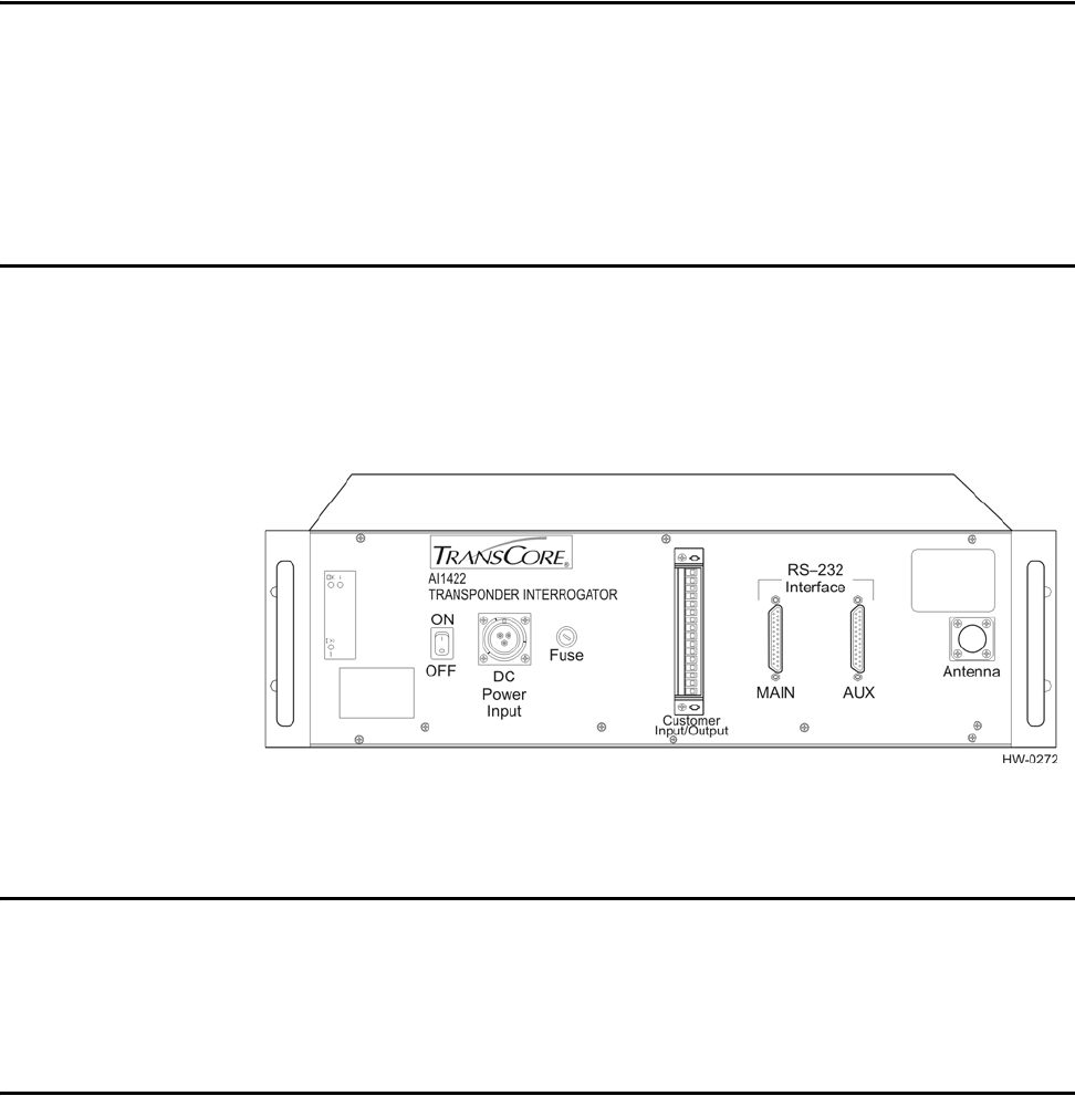
AI1422 Half-Frame Reader System front panel as shown in Figure 3-1.
Figure 3-1 Front Panel of AI1422 Transponder Interrogator
Antenna Interface
Attach the antenna cable directly to the antenna interface on the front panel of the
AI1422 Half-Frame Reader System. The antenna cable length depends on the installa-
tion.
Main RS–232 Interface
The main RS–232 interface is a standard DB25 plug connector used with a host pro-
cessor. During operation, a host processor system uses the reader system functions in
real-time operating mode. In real-time mode, tag IDs are read and passed on to the
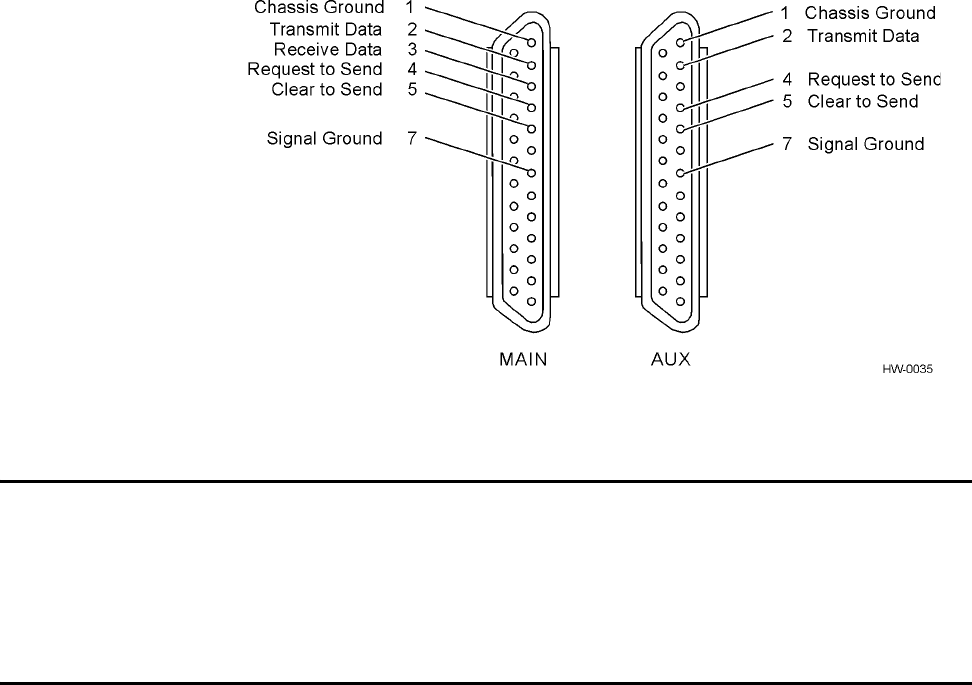
host processor. Figure 3-2 illustrates the RS–232, DB25 plug connector pin-outs.
AI1422 Half-Frame Reader System User Guide
3-4
Figure 3-2 RS–232, DB25 Interface Connector Pin-outs
Aux RS–232 Interface
The auxiliary RS–232 interface is used as a backup monitoring system to the main
RS–232 interface. The auxiliary interface monitors data from the transponder interro-
gator. The auxiliary RS–232 interface is a standard DB25 plug connector. This port is
not wired to receive data and cannot accept commands.
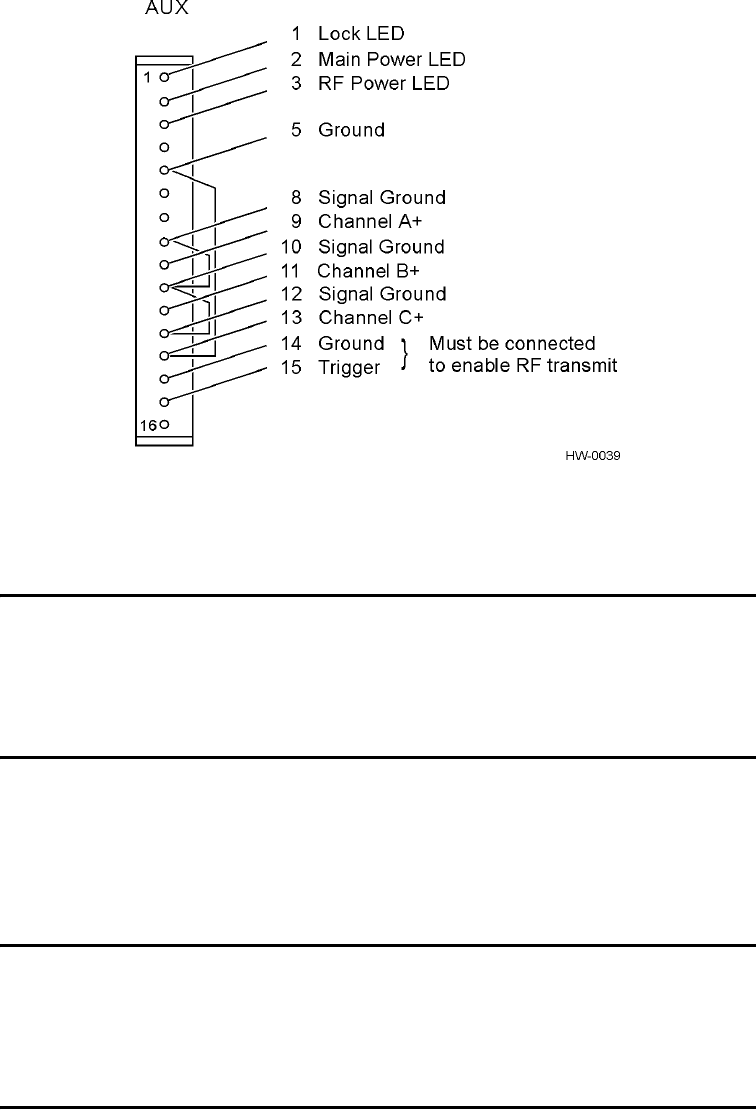
Customer I/O Interface
A mating connector for the customer I/O interface is supplied with each unit. This
connector allows a screw terminal, point-to-point wiring interface. Figure 3-3 shows
the pin-outs on the customer I/O interface connector.
Interface Connections
3-5
Figure 3-3 Customer I/O Interface Pin-outs
The customer I/O interface connector contains the lock light-emitting diode (LED),
main power LED, RF power LED, the trigger signals, and channels A, B, and C.
Lock LED
The transistor-transistor-logic (TTL) lock signal shows the presence of a tag. The lock
signal goes active high when a valid tag is in the RF field of the antenna and may be
connected to an LED for monitoring purposes.
Main Power LED
The TTL main power signal goes active high when the ON/OFF switch on the front
panel is switched to on. The switch is connected to +5V through a 300 ohm resistor
and is connected to an LED on the front panel, which may be used for power monitor-
ing purposes.
RF Power LED
The TTL RF power LED goes active high when the reader system is configured for
the RF power to be on and the ON/OFF switch is set to on. It is connected to +12V
through a resistor and may be connected to a LED for RF power monitoring purposes.
Trigger Signals
The trigger connection turns on the RF power when a ground is applied and the
AI1422 Reader System has been programmed with the RF Follows Trigger command
(!642).

AI1422 Half-Frame Reader System User Guide
3-6
Channels A, B, and C
The analog intermediate frequency channel A, B, and C signals represent the three
channels generated by the AI1422 Reader System. These channels can be used to
measure tag signal quality.
Power Connection
The power connector on the front panel of the AI1422 Half-Frame Reader System is a
panel mount circular connector of type Cannon CA 3100 E16-10P-F80-T12.

4
System Test Procedures

4-3
Chapter 4
System Test Procedures
This chapter provides testing procedures that will help you fine-tune
your reader system and test basic operation, measure radio frequency
(RF) power, measure system noise, read tags, and monitor the system.
Required Tools and Equipment
The following tools and equipment are required:
•50-ohm, 5-watt (W) load (N-type connector)
•Personal computer (PC) with terminal emulator software
•Appropriate power source for your reader
•Digital multimeter
•RF power meter
•100 MHz oscilloscope
•Antenna, cable, and connectors
Testing Basic Operation
To test the system operation, configure the reader system as outlined in the following
steps.
CAUTION
The following procedures will cause RF power to be turned on and off at various
times. Do not operate the system without a 50-ohm, 5-W load attached to the RF
output. When any RF cable is disconnected, the associated RF power measurement
unit must be turned off.
1. Connect a 50-ohm, 5-W load (termination) to the antenna interface located on the
front panel of the reader system.
2. Configure a terminal emulator (a PC running communications software) to 2400
or 9600 baud, no parity, 8 data bits, and 1 stop bit.
3. Connect the emulator to the main RS–232 interface located on the front panel of
the reader system.
4. Switch off the ON/OFF switch located on the front panel of the reader system.
AI1422 Half-Frame Reader System User Guide
4-4
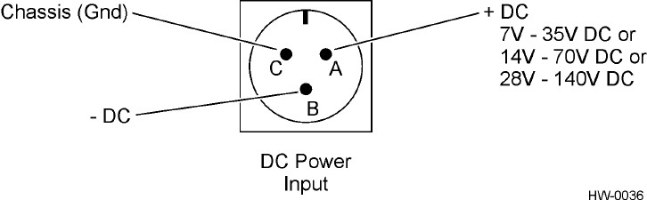
5. Connect a power source to pins A (+) and B (-) on the DC power input front
panel connector (Figure 4-1).
Figure 4-1 Power Source Connections
6. Switch on the ON/OFF switch located on the front panel of the reader system.
7. Type the command ~~CC (CC must be entered in upper case) and press
Enter.
Note: For information on entering command codes, refer to Chapter 5, Command
Codes.
8. Type !22 and press Enter. The time and date will be returned.
If the time and date are not received, check communications connections, cycle
power, and repeat.
If the time and date are incorrect, use !20 and/or !21 to correct this information,
then type the following commands.
!20hh:mm:ss sets time
!21MM/DD/YY sets date
!642 sets RF to follow the trigger
!41 enables tag reporting
The entered command and !Done response will be returned after each properly
executed command.
9. Connect a jumper between pins 14 (ground) and 15 (trigger) on the customer
input/output (I/O) connector to turn on the RF power. Figure 3-3 on page 3-5 in
Chapter 3 shows the location of pins 14 and 15.
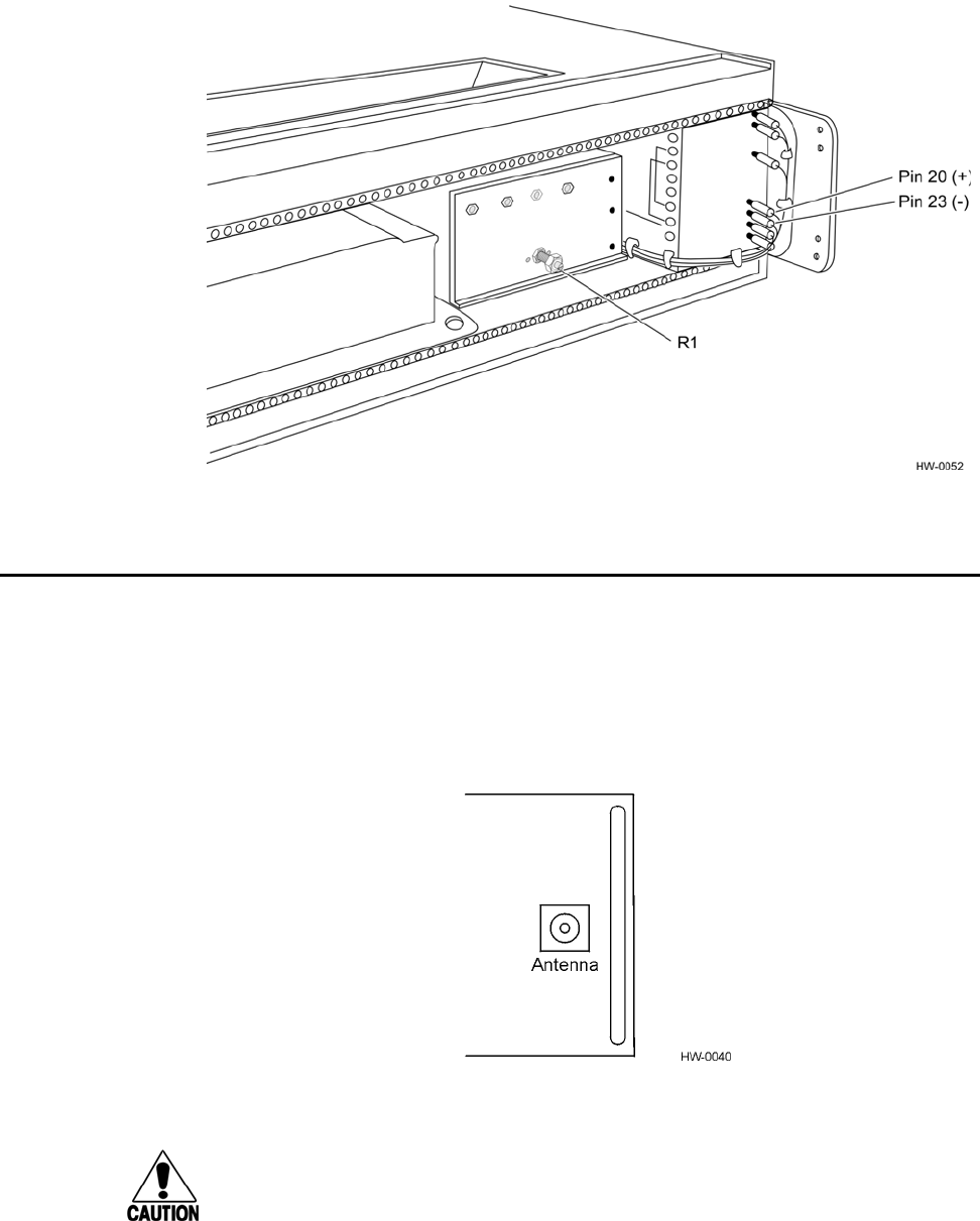
10. Connect a voltage output meter to pins 20 (+) and 23 (-) at the back of the
Melcher DC-DC converter. Figure 4-2 shows the location of pins 20 and 23.
11. Adjust the R1 knob (Figure 4-2) to obtain 13.5V DC.
System Test Procedures
4-5
Figure 4-2 Locations for DC Voltage Adjustment Measuring RF Power
Measuring RF Power
To measure the RF power
1. Set the ON/OFF switch located on the front panel of the reader system to off.
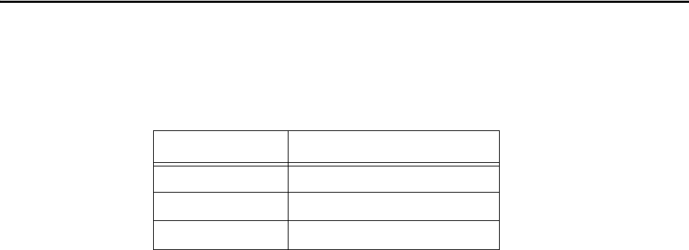
2. Connect an RF power meter of known accuracy to the antenna interface on the
front panel of the reader system (Figure 4-3). Power measured at the antenna
connector should be 0.8 W (29 dBm).
Figure 4-3 Antenna Interface on Front Panel
Caution
Some RF power meters have input power restrictions, and 0.8 W can severely dam-
age the RF meter if applied directly. Use supplemental attenuators of known accu-
racy with these types of meters and add the attenuation amount to the resulting RF
power measurement.
AI1422 Half-Frame Reader System User Guide
4-6
3. If a cable is used with the power meter, the cable loss must be determined by
measuring all cables with an RF power meter of known accuracy. Calculate the
resultant RF power levels using the formula dB = 10log P in/P out. Add this loss to
the meter reading to determine the actual RF power output.
4. Set the ON/OFF switch located on the front panel of the reader system to on.
5. Repeat steps 6 through 8 under the section “Testing Basic Operation” on page 4-
3 to configure the unit to operating conditions.The RF power measurement
should read greater than 0.8 W.
Example of RF power measurement with a 645-mW meter reading using a
cable:
10log 645 +28.1 dBm
Test cable loss 0.9 dB
Total +29.0 dBm = 0.8 W
Measuring System Noise
With the equipment configured the same as for the RF power measurement test
described above, connect a 100 MHz oscilloscope to the customer I/O interface
according to the parameters listed in Table 4-1.
Table 4-1 System Noise Test Parameters
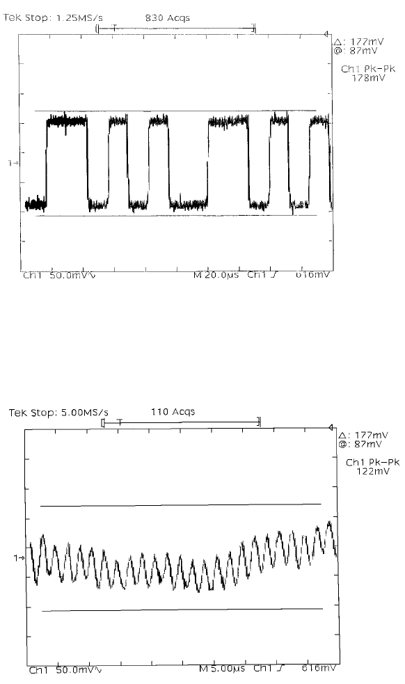
Figures 4-4 through 4-6 depict waveforms generated at selected channels, as shown by
an oscilloscope.
Figure 4-4 illustrates the desired waveform generated during normal operation with a
valid tag in the reader field.
Channel Pins
A8 (ground) and 9
B10 (ground) and 11
C12 (ground) and 13
System Test Procedures
4-7
Figure 4-4 Typical Waveform with a Tag in the Reader Field
Figure 4-5 depicts typical quiescent noise levels with the RF connector configured
with a 50-ohm, 5-W terminator. Quiescent noise levels vary from unit to unit with
channel C having the most representative noise level.
Figure 4-5 Typical Quiescent Noise Waveform
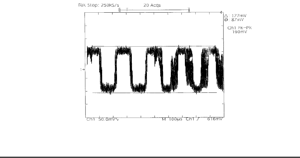
Figure 4-6 shows the typical beat frequency interference waveform caused by a simi-
lar frequency interrogator system connected to an antenna in proximity to the system
under test.
AI1422 Half-Frame Reader System User Guide
4-8
Figure 4-6 Typical Beat Frequency Interference Waveform
Reading the Tag
To verify that the AI1422 Half-Frame Reader System is properly reading tags
1. Switch the ON/OFF switch located on the front panel of the reader system to off.
2. Using your own cable, connect the laptop PC to the reader system at the main
RS–232 interface.
3. Connect the antenna to the antenna interface on the front panel of the reader
system.
4. Connect three customer-supplied light-emitting diodes (LED) between the
ground pin and lock LED, the ground pin and the main power LED, and the
ground pin and the RF power LED. All of these pins are located on the customer
I/O interface on the front panel of the reader system.
5. Set the ON/OFF switch located on the front panel of the reader system to on.
6. Connect a jumper between pins 14 (ground) and 15 (trigger) on the customer
I/O interface to trigger the RF on (Figure 3-3 on page 3-5).
7. Monitor the LEDs on the box, and verify that the main power LED and the RF
power LED are lit.
8. Position a programmed TransCore half-frame rail tag with a backplate within 2 to
3 feet (0.6 to 0.9 m) of the antenna. No other tag can be in this 2 to 3 foot (0.6 to
0.9 m) area during this test.
9. Verify that the lock LED is lit and that the PC is acquiring the tag data.
10. Remove the tag from the antenna field. The PC should stop reading the tag data.
System Test Procedures
4-9
11. Disable the trigger by disconnecting the jumper.
12. Set the on/off switch located on the front panel of the reader system to off.
Note: Repeat this test several times. Each time, the lock LED should be lit and the PC
should be reporting the tag data.
AI1422 Half-Frame Reader System User Guide
4-10

5
Command Codes

5-3
Chapter 5
Command Codes
This chapter describes the default and diagnostic command codes that
enable you to develop host computer programs to control the functions
of the AI1422 Half-Frame Reader System.
Default Command Codes
The default command codes enable communications between the host computer and
the reader system. These codes, also referred to as the communications protocol, are in
a binary format. TransCore strongly recommends that a person with software writing
capabilities write this communications protocol.
The transponder identification (ID) can be 3 or 10 bytes, which corresponds to 2400 or
9600 baud, respectively. These bytes are 6-bits coded. See Appendix A, “Character
Conversion,” of this user guide.
Asynchronous Reader Data Telegram
The reader system sends a data telegram when it reads a unique tag ID.
<7EH><7EH><01H><transponder count><transponder ID<CR>
Health Status Request
You will need to write a script file to download the following binary string for the
health status request.
<7EH><7EH><40><CR>
The response is
<7EH><7EH><02H><Transponder count><host computer
telegrams-bad CRC><incomplete host telegram>
<Reserved><Reserved><Reserved><CR>
Retransmit Request
You will need to write a script file to download the retransmit request.
<7EH><7EH><42H><CR>
The response is
<7EH><7EH><01H><transponder count><transponder ID><CR>

AI1422 Half-Frame Reader System User Guide
5-4
Diagnostic Command Codes
Diagnostic commands are used to check or fine-tune the reader system.
Diagnostic Command Code Syntax
Unlike default command codes that require a script file, diagnostic codes are typed by
the user. The general syntax of diagnostic commands is to begin with an exclamation
character, !, followed by the command code and a list of parameters. No spaces should
be between characters, and the command is sent by pressing Enter or carriage return
<CR>.
As characters are typed, they are automatically displayed on the terminal (except for
the ~~CC command). As soon as the command is terminated with Enter or a <CR>,
the reader system responds to the command as follows:
!Done command recognized and accepted
or
!Error command not recognized
The normal response is !Done. Other responses, for example, the time/date
response, provide a description of the entry made or command completed.
The reader system operates using two distinct command sets. The first command set
contains the system default commands when the system is turned on. The second
command set contains diagnostic and other fine-tuning codes.
Diagnostic Command Code Listing
The following commands are used for diagnostics or to fine-tune the reader system.
Escape Command
!~~CC
Pressing the escape command disables the reader system default command codes and
allows the reader system to accept the other diagnostic and fine-tuning command
codes.
The response is
No response is returned
Baud Rate Select
!100x
Command !100x selects the baud rate, where x = 0 to 6:
0 = 110 baud
1 = 300 baud
2 = 1200 baud
Command Codes
5-5
3 = 2400 baud
4 = 4800 baud
5 = 9600 baud (factory setting)
6 = 19.2 kbaud
The response is
!Done or !Error
Note: The !Done response is issued at the setting that existed before invoking the new
command. All subsequent communications will be at the new baud rate.
Stop Bits
!101x
Command !101x selects the stop bits, where x = 0 or 1:
0= 1 stop bit (factory setting)
1 = 2 stop bits
The response is
!Done or !Error
Note: The !Done response is issued at the setting that existed before invoking the new
command. All subsequent communications will be at the stop bit mode.
Parity Select
!102x
Command !102x is used to select parity, where x = 0 to 2:
0 = disable parity (factory setting)
1 = enable even parity
2 = enable odd parity
The response is
!Done or !Error
Note: The !Done response is issued at the setting that existed before invoking the new
command. All subsequent communications will be at the new parity mode.
Set the Time in the Real-Time Clock
!20hh:mm:ss
where
hh = hours (00–23)
AI1422 Half-Frame Reader System User Guide
5-6
mm = minutes (00–59)
ss = seconds (00–59)
The response is
!Done or !Error
Note: The time must be entered exactly as shown with no spaces between characters
and colons as delimiters. All entries use decimal characters 0 through 9.
Set the Date in the Real-Time Clock
!21MM/DD/YY
where
MM = month (01–12)
DD = day (01–31)
YY = year (00–99)
The response is
!Done or !Error
Note: The date must be entered exactly as shown with no spaces between characters
and with forward slashes (/) as delimiters. All entries use decimal characters 0
through 9.
Display Time and Date
!22
where
hh = hours (00–23)
mm = minutes (00–59)
ss = seconds (00–59)
dd = hundredths of seconds
MM = month
DD = day
YY = year
The response is
!hh:mm:ss.dd MM/DD/YY
or
!Error
Note: There are two spaces between the time and the date.
Command Codes
5-7
Real-Time Transmission to Host Enabled (factory setting)
!305
When a tag identification (ID) is acquired by the radio frequency (RF) source, it is
immediately sent out on the RS–232 port. The tag ID is not stored in the data buffer.
The response is
!Done or !Error
Transmit All Tag ID Codes
!41
Command !41 transmits to the host computer all tag IDs received by the antenna.
The response is
!Done or !Error
Note: This command is to be used for diagnostic purposes only.
Return to Default Command Codes
!63
Command !63 returns the host computer to the default command codes.
The response is
No response is returned
RF Follows Trigger
!642
Command !642 switches RF power on continuously.
The response is
!Done or !Error
Note: This command is for diagnostic purposes only.
AI1422 Half-Frame Reader System User Guide
5-8

6
Troubleshooting

6-3
Chapter 6
Troubleshooting
This section lists routine maintenance procedures to keep the AI1422
Half-Frame Reader System operating correctly and diagnostic
procedures for troubleshooting an improperly working reader system.
Required Tools and Equipment
The following tools and equipment are required:
•50-ohm, 5-watt (W) load (N-type connector)
•Personal computer (PC) with terminal emulator software
•Appropriate power source for your reader
•Digital multimeter
•RF power meter
•100 MHz oscilloscope
•Antenna and cable
Troubleshooting
No loop-back mode to restore defaults, such as baud rate, means that troubleshooting
is required.
Failure Modes
No Communication — To determine if there is a problem in the communications
hardware, the following two commands should be repeated together for testing pur-
poses:
!~~CC escape to diagnostic mode
!22 display time and date
If functioning properly, the time and date will be displayed after the second command,
which means that the reader is communicating. If the reader is not functioning prop-
erly, then perform the following checks.
•Does the AI1422 Half-Frame Reader System have adequate power? If not, ensure
reader has 13.5V DC ±1.0V DC.
•Is the main power switch on? If not, switch it on.

AI1422 Half-Frame Reader System User Guide
6-4
•Is the main power switch light-emitting diode (LED) lit? If not, turn on power
switch.
•Is the front panel fuse blown? If so, replace it with a 1.5 amp (A) slo-blo fuse.
•Is the reader’s DC-DC converter functioning? If so, the OK LED on upper left
corner of front panel will be lit.
•Are you using a null modem cable connection? If not, switch to a null modem
connection.
•Have you set the correct baud rate? If an incorrect baud rate is suspected, select
and send each baud rate in turn, using the !100x Baud Rate Select command, and
wait for a response.
Unit Will Not Read Tags
The suggestions listed here assume that the user has already verified proper serial
communications, and the command !305 has been entered successfully to enable
real-time transmission to the host computer. If RF POWER LED, which is recom-
mended for customer I/O connector, is lit, the indication is that the AI1422 is querying
for tags. If the LOCK LED, which is recommended for the customer I/O connector, is
lit, the indication is that the reader system is retrieving tag data. If either LED is not lit,
then check the following items:
•Verify that the antenna connection is good.
•Verify that the antenna cable is in good condition.
•Verify that a single, known valid tag is in the antenna field.
•Verify that the trigger remains activated and the unit power is on.
•Verify that a tag being alternated with a tag containing different data to avoid
uniqueness filtering.
Unit Will Not Retain Settings
If the unit will not retain information, such as time and date stamp or baud rate
between power cycles, the internal battery backup has failed and the unit must be
returned for repair. Contact TransCore at the telephone number listed at the front of
this user guide.
Maintenance Procedures
Except for the 1.5-A slo-blo fuse in the front panel of the unit, there are no user-ser-
viceable parts in the AI1422 Half-Frame Reader System.

A
Character Conversion

A-3
Appendix A
Character Conversion
Table A-1 lists the TransCore 6-bit-per-character conversion from the standard ASCII
character set.
Table A-1 TransCore 6-Bit-Per-Character Conversion
spc 000000 6010110 L101100
!000001 7010111 M101101
"000010 8011000 N101110
#000011 9011001 O101111
$000100 :011010 P110000
%000101 ;011011 Q110001
&000110 <011100 R110010
'000111 =011101 S110011
(001000 >011110 T110100
)001001 ?011111 U110101
*001010 @100000 V110110
+001011 A100001 W110111
,001100 B100010 X111000
-001101 C100011 Y111001
.001110 D100100 Z111010
/001111 E100101 [111011
0010000 F100110 \111100
1010001 G100111 ]111101
2010010 H101000 ^111110
3010011 I101001 _111111
4010100 J101010
5010101 K101011
AI1422 Half-Frame Reader System User Guide
A-4

B
Technical Specifications

B-3
Appendix B
Technical Specifications
Table B-1 lists the specifications of the AI1422 Half-Frame Reader System.
Table B-1 AI1422 Half-Frame Reader System Specifications
Specification Description
Size 19.0 x 5.25 x 9.0 in
(48.3 x13.34 x 22.9 cm)
Weight 12.0 lb (5.4 kg)
Operating temperature +32°F to +158°F (+0°C to +70°C)
Power requirement 13.5V DC ±1.0V DC @25W
Available frequency range 902–928 MHz
Approved frequency range for
Federal Communications
Commission and Industry Canada
902.25–903.75 MHz and
910.00–921.50 MHz
Receiver RF bandwidth ≅1.2 MHz
Receiver sensitivity -48 dBm
Transmitter frequency stability ±5.0 ppm over operating temperature
range
Transmitter RF power 0.8W ±0.1W
Communications port RS–232, 110 to 19,200 baud
Other features
Real-time calendar clock
Optional 8V–32V DC, 14V–70V DC, or
28V-140V DC power supply
AI1422 Half-Frame Reader System User Guide
B-4

C
Diagnostic Command Codes List

C-3
Appendix C
Diagnostic Command Codes List
Command Function
!~~CC Escape (CC must be entered in upper case)
!100x Baud Rate Select
!101x Stop Bits
!102x Parity Select
!20hh:mm:ss Set the Time in the Real-Time Clock
!21MM/DD/YY Set the Date in the Real-Time Clock
!22 Display Time and Date
!305 Real-Time Transmission to Host Enabled (factory setting)
!41 Transmit All Tag ID Codes
!63 Return to Default Command Codes
!642 RF Follows Trigger
AI1422 Half-Frame Reader System User Guide
C-4