Transact Campus WR5000X012 WR5000 User Manual WR5000 Installation Guide
Blackboard Inc. WR5000 WR5000 Installation Guide
Installation Guide

403-003-000 Rev A
Blackboard Wall Reader (WR5000)
Installation Guide

403-003-000 Rev A
Table 1: Revision History
Bb Document Part Number Rev. Description Date
403-003-000 A ECO10418. Initial Release. PENDING

CONTENTS
403-003-000 Rev A I
1BLACKBOARD (WR5000) READER INSTALLATION GUIDE
2 Federal Communications Commission (FCC) statement
4 Hardware Kit and Parts List
5 Reader Installation Overview
5 Reader Wiring
5 Door Reader RS-485 Interface
6 Door Reader Wiegand Interface
7 Attendance Reader
8 Reader Mounting
10 Specifications
BLACKBOARD (WR5000) READER INSTALLATION GUIDE
403-003-000 REV A 1-1
BLACKBOARD (WR5000) READER INSTALLATION GUIDE
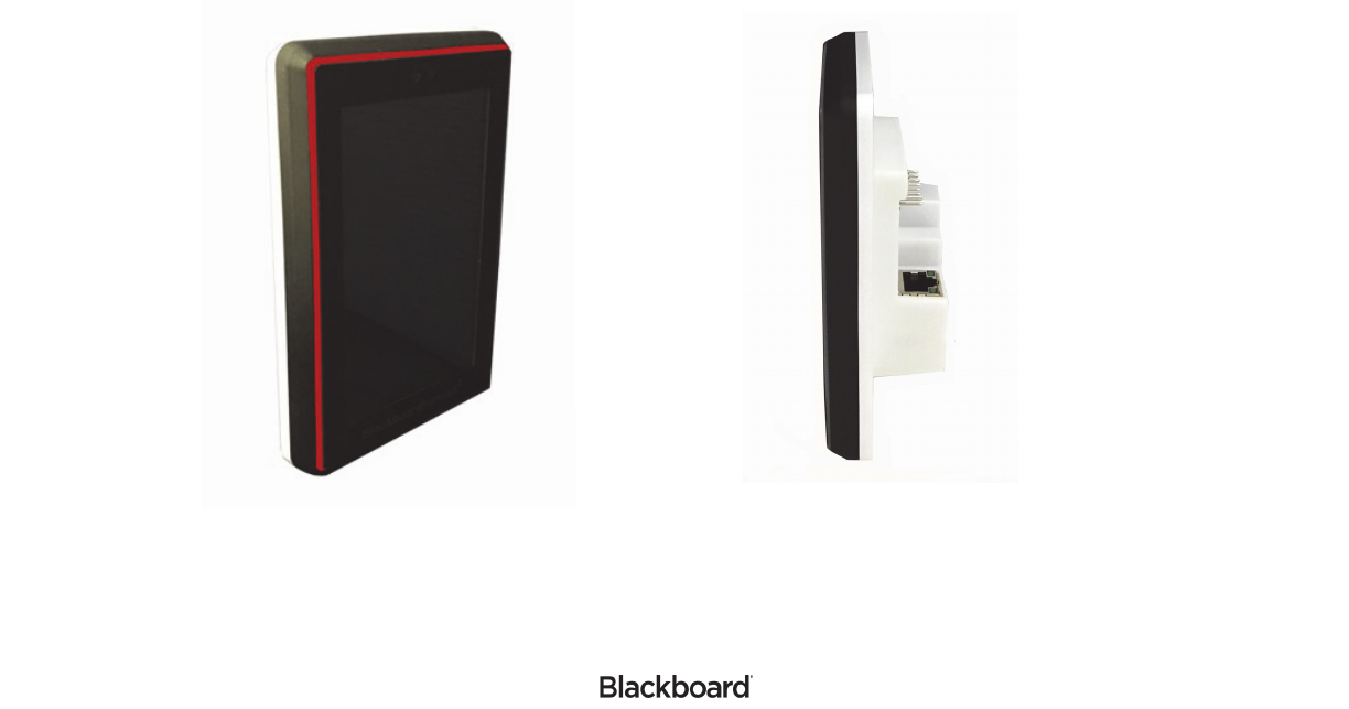
The Blackboard Wall Reader, Model WR5000, is a device for reading Blackboard contactless cards and
other credentials that use Near Field Communications (NFC) technology. The reader supports two modes
of operation; a door reader that interfaces to either the Blackboard Security Access System or third-party
control panels using a Wiegand interface. A second mode of operation is as an attendance reader.
Features:
• 4.0” LCD (480 x 800) with capacitive touch panel
• Configuration via touchscreen/display
•NFC technology
• RS-485 Serial Interface
• Bluetooth Low Energy (BLE)
• Host communications via 10/100 Base-T Ethernet (IP) or 802.11 b/g/n wireless
• Encrypted and authenticated IP communications
Figure 1-1 Blackboard WR500 Reader

FEDERAL COMMUNICATIONS COMMISSION (FCC) STATEMENT
403-003-000 REV A 1-2
FEDERAL COMMUNICATIONS COMMISSION (FCC) STATEMENT
This device complies with Part 15 of the FCC Rules. Operation is subject to the following two conditions:
1. This device may not cause harmful interference.
2.This device must accept any interference received, including interference that may cause undesired
operation.
Note: This equipment has been tested and found to comply with the limits for a Class A digital device,
pursuant to Part 15 of the FCC Rules. These limits are designed to provide reasonable protection against
harmful interference when the equipment is operated in a commercial environment. This equipment
generates, uses, and can radiate radio frequency energy, and if it is not installed and used in accordance
with the instruction manual, it may cause harmful interference to radio communications. Operation of this
equipment in a residential area is likely to cause harmful interference, in which case the user will be
required to correct the interference at his own expense.
Modifications: Any modifications made to this device that are not approved by Blackboard Inc. may void
the authority granted to the user by the FCC to operate this equipment.
IMPORTANT NOTE: This equipment complies with the FCC radiation exposure limits set forth for an
uncontrolled environment. End users must follow the specific operating instructions for satisfying RF
exposure compliance. The antenna(s) used for this transmitter must be installed to provide a separation
distance of at least 20 cm from all persons and must not be co-located or operating in conjunction with any
other antenna or transmitter.
Contains:
Industry Canada Class A emission compliance statement
This Class A digital apparatus complies with Canadian ICES-003.
Cet appareil numérique de la classe A est conforme à la norme NMB-003 du Canada.
FCC ID: 2AFDI-ITCOQ410S Intrinsyc Open-Q 410 System-On-Module
FCC ID: WAP2005 Cypress Semiconductor Bluetooth Low-Energy Module (CYBLE-222014-01)

BLACKBOARD (WR5000) READER INSTALLATION GUIDE
403-003-000 REV A 1-3
This device complies with Industry Canada licence-exempt RSS standard(s). Operation is subject to the
following two conditions: (1) this device may not cause interference, and (2) this device must accept any
interference, including interference that may cause undesired operation of the device.
Le présent appareil est conforme aux CNR d’Industrie Canada applicables aux appareils radio exempts de
licence. L’exploitation est autorisée aux deux conditions suivantes: (1) l’appareil ne doit pas produire de
brouillage, et (2) l’utilisateur de l’appareil doit accepter tout brouillage radioélectrique subi, même si le
brouillage est susceptible d’en compromettre le fonctionnement.
Contains:
Contient des IC: 9049A-ITCOQ410S and 7922A-2005
Australia and New Zealand Class A statement
Attention: This is a Class A product. In a domestic environment this product may cause radio interference
in which case the user may be required to take adequate measures.
Radiation Exposure Statement
This equipment complies with radiation exposure limits set forth for uncontrolled environment. The
antenna(s) used for this transmitter must be installed to provide a separation distance of at least 20 cm
from all persons and must not be collocated or operating in conjunction with any other antenna or
transmitter.
Déclaration d'exposition aux radiations
Cet appareil se conforme aux limites d'exposition aux rayonnements pour un environnement non contrôlé.
L'antenne (s) qui est utilisé pour cet émetteur doit être installé pour produire une distance de séparation
d'au moins 20 cm de toutes personnes et ne doit pas être installé à proximité ou utilisé en conjonction avec
une autre antenne ou émetteur.
IC: 9049A-ITCOQ410S Intrinsyc Open-Q 410 System-On-Module
IC: 7922A-2005 Cypress Semiconductor Bluetooth Low-Energy Module (CYBLE-222014-01)
HARDWARE KIT AND PARTS LIST
403-003-000 REV A 1-4
HARDWARE KIT AND PARTS LIST
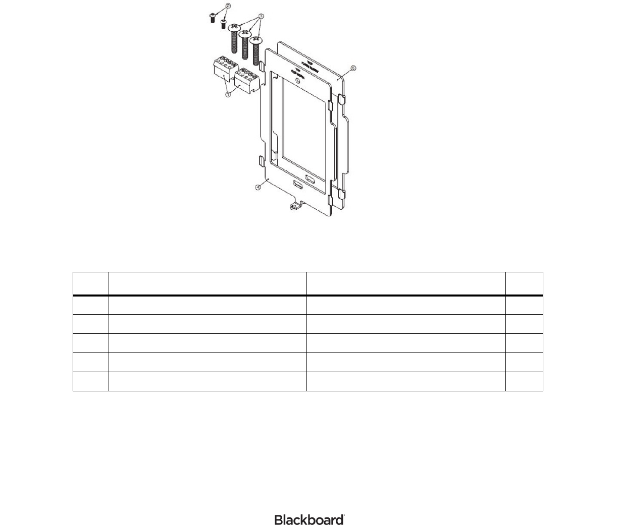
A hardware kit is included with the WR5000. These components are used for wire termination and
installation to a single gang-box.
Figure 1-2 Hardware Kit
Table 1-1: Hardware Parts List
Item Description Use Qty
1 1 x 4m 3,5mm Terminal Block Attach wires to reader. 2
2 M2 x 5 Button-head Socket Cap Screw Secure Reader to mounting plate. 2
3 6-32 x ¾" FH Machine Screw Secure Mounting plate to gang-box. 3
4 Mounting bracket - Old Work Old Work - gang-box tabs on wall surface. 1
5 Mounting bracket - Flush Mount New Work - gang-box is flush with wall. 1

BLACKBOARD (WR5000) READER INSTALLATION GUIDE
403-003-000 REV A 1-5
READER INSTALLATION OVERVIEW
When choosing a location to install the WR5000 reader, consider the following:
• Proximity to entry point
• Visibility and Access to Users
• ADA Requirements
• Protection of the reader from environmental elements
• Cable distance/path:
1200 ft. maximum for RS-485 to Blackboard SA3032
500 ft. maximum for Wiegand interface
500 ft. maximum for Wiegand interface
328 ft. maximum for Cat-5e cable
Reader Wiring
Based on the application of the reader, the wiring options are as follows:
•Door Reader RS-485 Interface (page 1-5)
•Door Reader Wiegand Interface (page 1-6)
•Attendance Reader (page 1-7)
The hardware kit includes two (1 x 4) terminal blocks. These terminal blocks provide electrical connections
to signals on the pin headers.
Two WR5000 readers can be connected to the Blackboard Access SA3032 to support ingress and egress
configurations. The administrator must login to each reader and set the address. Verify that the readers do
not have the same assigned address (0 or 1).
Note: To maintain UL compliance, install only 1 wire in each terminal block opening. If
necessary, use an external splice when more than one wire is required.
Install in accordance with the National Electrical Code (NEC), ANSI/NFPA 70, and local codes.
Door Reader RS-485 Interface
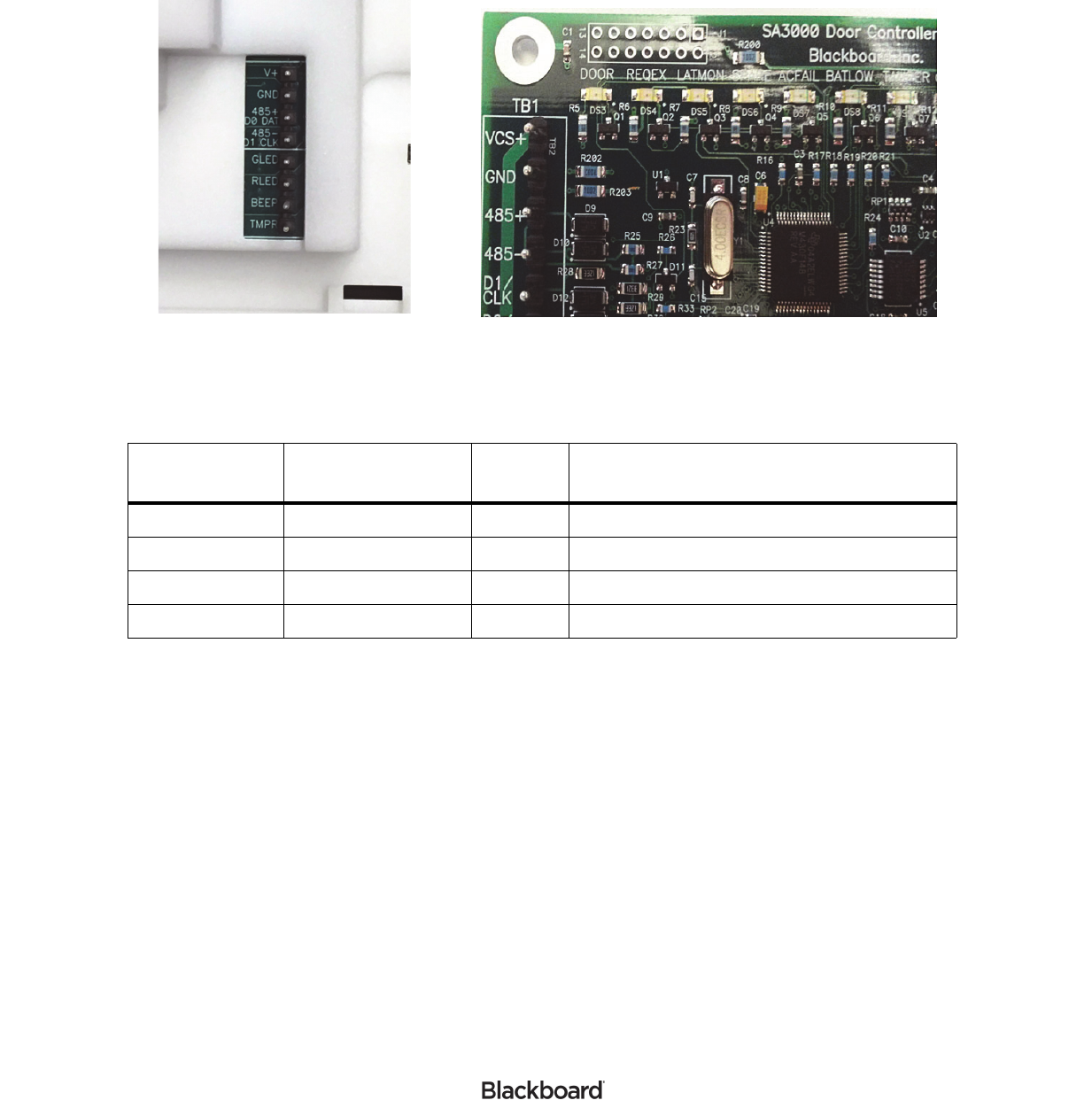
When using the RS-485 Interface option, only one terminal block is required. The connection points are
shown in Table 1-2. The TB1 designation is for the top four pins shown in Figure 1-3.
READER INSTALLATION OVERVIEW
403-003-000 REV A 1-6
Figure 1-3 Terminal Blocks
The reader must be configured by the administrator to operate in RS-485 mode. In addition to the wiring
shown above, the reader can also be connected to a network using the RJ-45 connector. This provides a
means of getting software updates for the Android OS.
Door Reader Wiegand Interface
When connecting the reader to a Third-party Controller using a Wiegand interface, both terminal blocks are
required. Cable wiring should be a minimum of 24 AWG. If a shielded cable shield is used, ground the
shield at the panel only. Grounding at both ends can cause ground loops which can be disruptive.
For Wiegand Connection Points, see: Table 1-3:.
Table 1-2: RS-485 Connection Points
WR5000
Terminal Block
SA3032 Door
Controller
Signal
Name Description
TB1-1 TB1-1 V+ Power Input +
TB1-2 TB1-2 GND Power Return -
TB1-3 TB1-3 485+ Serial Interface +
TB1-4 TB1-4 485- Serial Interface -
WR5000 Terminal Block Door Controller Terminal Block

BLACKBOARD (WR5000) READER INSTALLATION GUIDE
403-003-000 REV A 1-7
The reader must be configured by the administrator to operate in Wiegand mode. In addition to the wiring
shown above, the reader can also be connected to a network using the RJ-45 connector. This provides a
means of getting software updates for the Android OS.
Attendance Reader
When using the WR5000 as an attendance reader, the device must be connected to a network.
The WR5000 can be powered using an external power supply, or a Power Over Ethernet (POE) switch. If
using an external power supply, the power supply must have a regulated output of +12 Volts DC. If using
POE, a CAT-5 cable must be connected between the POE switch and the RJ-45 connector on the WR5000
(cable length must not exceed 100 meters).
WARNING: When using a POE switch to power the WR5000, both the POE switch and
WR5000 must be installed within the same building or structure.
When using an external supply, wire the reader as shown in Table 1-4:
Table 1-3: Wiegand Connection Points
WR5000
Terminal Block Signal Name Third-Party Controller connections
TB1-1 V+ Connect to regulated Power Supply (+6V to +24V)
TB1-2 GND Connect to Ground
TB1-3 D0/DAT Connect to Wiegand D0 input
TB1-4 D1/CLK Connect to Wiegand D1 input
TB2-1 GLED Connect to Green LED output
TB2-2 RLED Connect to Red LED output
TB2-3 BEEPER Connect to Beeper output
TB2-4 TAMPER Connect to Tamper Input
Table 1-4: Power Supply Wiring
WR5000
Terminal Block Signal Name External Power supply
TB1-1 V+ Connect to regulated Power Supply (+6V to +24V)
TB1-2 GND Connect to Ground
READER MOUNTING
403-003-000 REV A 1-8
READER MOUNTING
The WR5000 is designed to mount to a single gang-box. Each reader ships with a hardware kit that
includes screws and two mounting brackets. The mounting brackets are similar except for the height of the
four ramped hooks which position the reader against the wall. The brackets are marked to show orientation
and application.
To mount the reader
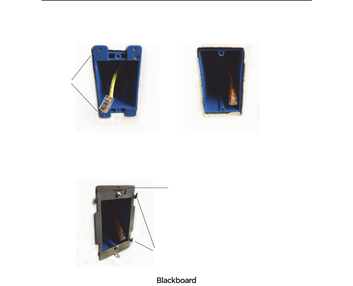
1Use the bracket marked OLD WORK when the gang-box has tabs on the outside of the wall. Use the
bracket marked FLUSH MOUNT when the gang-box is recessed or flush with wall (see: Figure 1-4).
Figure 1-4 Flush Mount & Old Work
2Choose the correct bracket for your application, and then install the bracket onto the gang-box using
the two truss-head screws provided in the hardware kit.
Be sure to orientate the bracket with the TOP marking as shown in Figure 1-5.
Figure 1-5 Flush Mount Installation With Bracket
FLUSH MOUNT
OLD WORK
Tab s
TOP marking
Ramp Hooks
BLACKBOARD (WR5000) READER INSTALLATION GUIDE
403-003-000 REV A 1-9
Note: The Flush Mount installation uses the mounting bracket with the taller ramp hooks.
3Connect wiring to the reader.
4Place the reader on the mounting bracket by gently placing it over the ramp hooks, and then moving it
downward until it stops.
Orientate the reader so that the Blackboard logo is at the bottom.
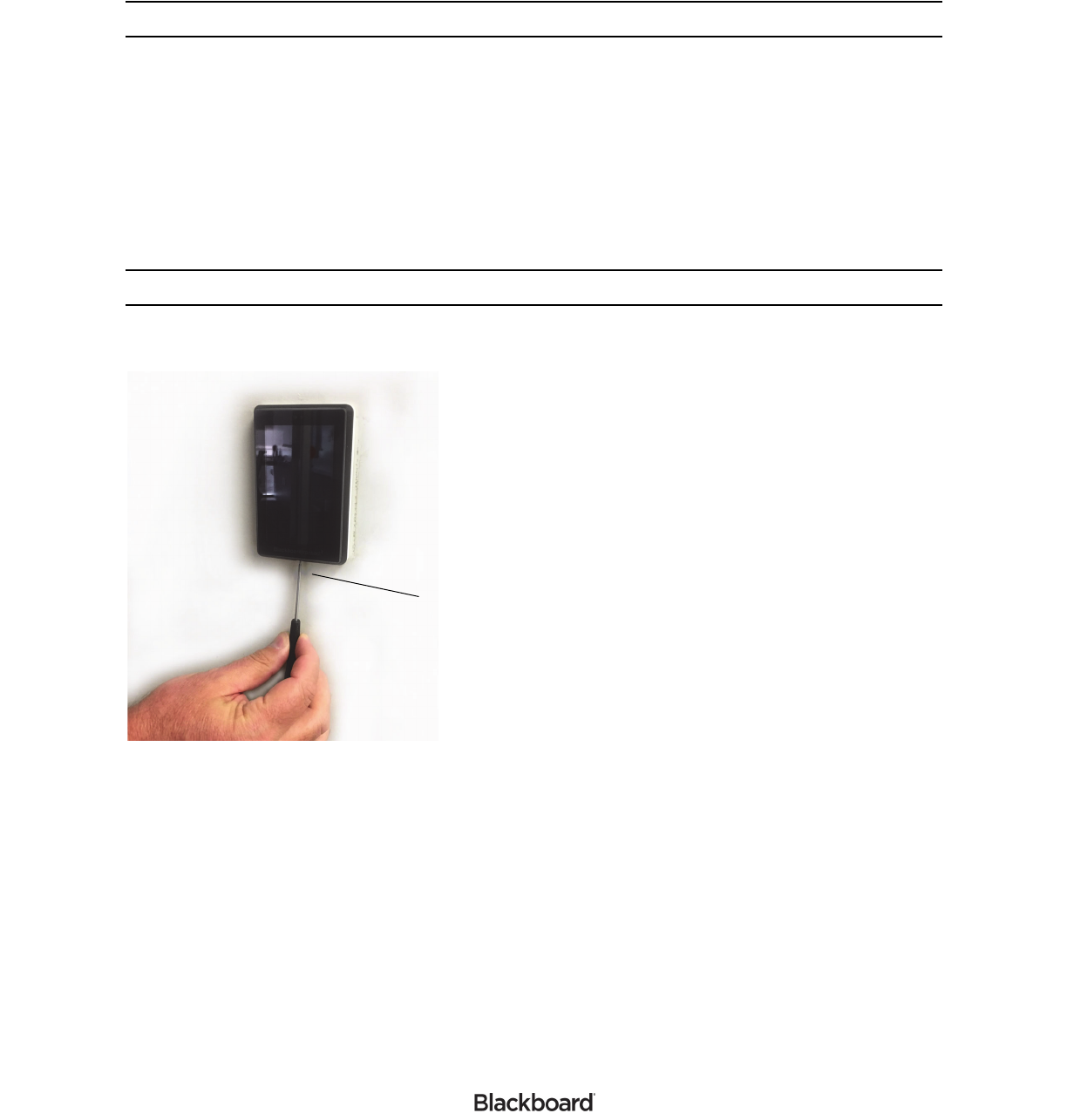
5Using a Hex Driver, install one M2 x 5 Button-head Socket Cap Screw to secure the reader to the
mounting bracket.
Note: Install the Socket Cap Screw from the bottom of the reader as shown in Figure 1-6.
Figure 1-6 Securing Reader to the Bracket
6Verify that the reader is securely in place.
Secure the reader using
one M2 x 5 Button-head Socket Cap Screw

SPECIFICATIONS
403-003-000 REV A 1-10
SPECIFICATIONS
Physical Size 2.95” W x 4.55” H x 1.40”D (extends 0.6” from wall surface when mounted)
Input Power 6 to 24 VDC (3.6 W max.)
Operating Temperature 0 to +50 Celsius (Indoor Use Only)
Storage Temperature -20 to +70 Celsius
Inputs (See Note 1) 0 to 5.5V
Wiegand Input Signals RLED, GLED, BEEPER
• 0 - 5.5V maximum
• Active when < 2.5V (driver must be able to sink at least 1mA)
Wiegand Output Signals D0, D1, TAMPER
• Open-drain outputs, max sink current 100 mA
• Internal 10K pullup to +5V
• TAMPER output polarity is configurable