Transamerica Broadcasting EM500DIG 500 Watt FM Broadcast Transmitter User Manual PORTADA ING
Transamerica International Broadcasting Inc 500 Watt FM Broadcast Transmitter PORTADA ING
User Manual
TECHNICAL MANUAL
v1.0 April 2012
F
FM
M
B
BR
RO
OA
AD
DC
CA
AS
ST
T
T
TR
RA
AN
NS
SM
MI
IT
TT
TE
ER
R
E
EM
M
5
50
00
0
H
HE
E
D
DI
IG
G
P
PL
LU
US
S
C
CO
OM
MP
PA
AC
CT
T
OMB EUROPE
OMB USA
Polígono Industrial Centrovía
Calle Paraguay, 6
50198 - La Muela
Zaragoza, ESPAÑA
3100 NW 72nd. Avenue Unit 112
MIAMI, Florida 33122 USA
Telf.: (305) 477 0973
(305) 477 0974
Fax: (305) 477 0611
Web: http://www.omb.es
E-mail: europa@omb.com
Web: http://www.omb.com
E-mail: usa@omb.com
Telf. : +34 976 14 17 17
Fax: +34 976 14 17 18

Certif. nº ES08-002-A Certif. nº ES08-002-B
OMB ESPAÑA
Polígono Industrial Centrovía
Calle Paraguay, 6
50196 – La Muela
Zaragoza (ESPAÑA)
Ph: +34 976 14 17 17
Fax: +34 976 14 17 18
Web: http://www.omb.es
E-mail: europa@omb.com

LIMITED WARRANTY
About Installation_____________________________________________________________
1. - Mains Voltage must be kept between ±10% about its nominal value, unless otherwise
specified. If were variations exceeding this tolerance, it will be indispensable to install a voltage
stabilizer system within station. If transient overvoltages, due to electric motors, or other devices
of this sort connected to the distribution line, were present, or if the distribution line is exposed
to atmospheric electrical discharges, it must be indispensable the installation of isolation
transformers and gaseous dischargers before connecting any equipment within station.
2. - All equipments must be connected to station ground system in order to avoid damage
both to equipments and maintenance personnel too. It is necessary to connect a differential
automatic switch (lifesaver) at station.
3. - Some equipments does not include interlock protection for open doors, covers or
connectors. In that case, these equipments must be kept in key –locked places, with access
only to conveniently qualified personnel that is previously noticed about not to open doors,
covers or connectors without disconnecting station mains switch before performing this job.
4. - Transmitter equipments NEVER will be operated with output powers over its nominal values,
or with signals or input informations others than those specified in its individual characteristics.
5. - Ambient temperature inside equipments' room, will accomplish technical specifications of
equipments installed at station lodge. In absence of such specifications, maximum allowable
temperatures will be from -5 to + 45ºC for Television equipments, and from 0 to + 40ºC for
Sound Broadcast equipments.
6. - In case of operation at abnormally high or extremely high temperatures (over 30 to 40 º
C), it is obligatory to install a forced cooling system that will keep temperature below its upper
limit. In case of operation at abnormally or extremely low temperatures, it will be obligatory to
install a thermostatic controlled heating system for equipment's room.
7. - Both equipment's surroundings and room must be free of dust and dirt. Ambient relative
humidity will be kept below equipment's extreme specifications. In case of absence of this
specification, allowable maximum will be 90 % of relative humidity, non-condensing. Average
relative humidity will be kept under 70%, non-condensing.
8. - Every transmission equipment that can radiate some quantity of RF power, must be
connected to a load or antenna system, suited to its individual specifications , before being
energized.
9. - Maximum allowable VSWR in antenna systems both for Television or FM Radio Broadcast
operation of a given transmitter, will be 1.25:1, unless otherwise specified.
10.- For those transmitter equipments having power valve amplifiers, and that doesn't has an
automatic shutoff cycle, and must be manually turned off, as a first step high voltage, or
anode voltage, will be disconnected, keeping forced cooling system working during at least 5
minutes after high voltage disconnection, and only after this time, cooling system & filament
voltage can be shutted off. O.M.B. Sistemas Electrónicos, S.A., is not responsible of damages
to those power valves caused by sudden AC mains failures at station where our equipments
are installed.
11.- Periodically, monthly as a maximum, technical personnel must visit station in order to
perform a general equipment maintenance, unless otherwise specified. This maintenance will
include output power check, VSWR of antenna systems, forced cooling or heating systems
checks, both for equipments and station itself, including air filters cleaning, measuring of
transmission frequency with eventual correction if necessary, and will perform a general check
of fundamental parameters of equipments. In the event of any important change in some
operation parameter, that will require replacement or readjustment of any unit, Customer
MUST CONTACT FIRST WITH O.M.B. SISTEMAS ELECTRONICOS, S.A. BEFORE ANY ATTEMPT TO
READJUST OR REPLACE ANY COMPONENT OR UNIT INSIDE EQUIPMENTS, IN ORDER TO KEEP
VALID THIS WARRANTY.
12.- For equipments who are located in fixed racks or cabinets, those equipments must be
effectively connected, according to International Installations Standards, to station ground
system, whose total impedance measured to ground can't be higher than 5 ohms.
Equipments must be connected to ground system so that they can be kept out of main
discharge path between tower and ground.
About Transportation___________________________________________________________
1. - O.M.B. Sistemas Electrónicos, S.A. is not responsible of damages and/or detriments derived
from mishandling, steal, robbery, theft or vandalism during the act of transportation of
equipments to final or intermediate destination.
About Storage________________________________________________________________
1. - O.M.B. Sistemas Electrónicos, S.A. is not responsible of damages and/or detriments derived
from unappropiate storage of equipments, within inadequate warehouses or outdoors, once
equipments are delivered to transportist agency.
About Projects________________________________________________________________
1.- O.M.B. Sistemas Electronicos, S.A. is not responsible of inadequate use of equipments
made or registered by our Company, accomplishing propagation projects that are not
performed by our Specialists.
About Systems________________________________________________________________
1.- O.M.B. Sistemas Electrónicos, S.A. is not responsible for performance of those equipments
or systems that are not made, certified or registered by our Company.
About Operation______________________________________________________________
1.- O.M.B. Sistemas Electrónicos, S.A. is not responsible of damages and/or detriments derived
from inadequate or negligent operation of equipments made, certified or registered by our
Company, once those equipments are operated by personnel hired and/or employed by
Customer.
General______________________________________________________________________
This Warranty covers and protects, during a period of 18 months after start of operations, all
equipments made , certified or registered by O.M.B. Sistemas Electrónicos, S.A., including its
components and units, against failures in workmanship that may occur during operation of
those equipments, with the exception of power valves or semiconductor devices that are
covered by its particular Factory's Guarantee. In this case, O.M.B. Sistemas Electrónicos, S.A.
only can act as intermediary for negotiation with such Factory, about accomplishment of
individual Guarantees.
For Validity of this Warranty, it is indispensable that all Paragraphs be respected by the
Customer. Otherwise, this Warranty will be automatically voided. This Warranty is self-activated
with the reception by OMB Sistemas Electrónicos, S.A. of the "Guarantee Activation Manual"
returned to OMB by Customer. If such Document is not received, this Warranty will be
voided.
All repairings or adjustments covered by this Warranty are free of workmanship & materials
costs and expenses, but postage and transportation expenses of equipments and O.M.B.
technical personnel & specialists, if required, will be carried out by the Customer.
O.M.B. Sistemas Electrónicos, S.A.

FM Transmitter
EM 500 DIG PLUS
Technical Manual - v1.0 - April 2012
1
LIST OF CONTENTS
SECTION 0. GENERAL RECOMMENDATIONS 2
Gives information on safety procedures and good practices to use the equipment.
SECTION 1. INTRODUCTION 9
Introduction to the manual, technical specifications and description of the equipment’s features.
SECTION 2. OPERATION 18
Contains a deep description of the system operation.
SECTION 3. INTERNAL MODULES 57
Contains the schematics of the different modules included in the equipment.

FM Transmitter
EM 500 DIG PLUS
Technical Manual - v1.0 - April 2012
2
S
Se
ec
ct
ti
io
on
n
0
0
G
GE
EN
NE
ER
RA
AL
L
R
RE
EC
CO
OM
MM
ME
EN
ND
DA
AT
TI
IO
ON
NS
S

FM Transmitter
EM 500 DIG PLUS
Technical Manual - v1.0 - April 2012
3
GENERAL SAFETY RECOMMENDATIONS
When connecting the equipment to the Mains power, please follow these important
recommendations:
• This product is intended to operate from a power source that will not apply more than
10% of the voltage specified on the rear panel between the supply conductors or between
either supply conductor and ground. A protective-ground connection by means of the
grounding conductor in the power cord is essential for a safe operation.
• This equipment is also grounded through the grounding conductor of the power cord. To
avoid electrical shock, plug the power cord into a properly wired socket before connecting
to the product input or output terminals.
• Upon loss of the protective-ground connection, all accessible conductive parts (including
parts that may appear to be insulated) can render an electric shock. Equipment must be
connected to station's ground system before any attempt to connect it to Mains
electrical supply.
• To avoid fire hazard, use only fuses of the type, voltage rating, and current rating specified
in this manual. For fuse replacement, always refer to User’s Manual.
• To avoid explosion, do not operate this equipment in an explosive atmosphere.
• To avoid personal injury, do not remove the product covers or panels. Do not operate the
product without the covers and panels properly installed.

FM Transmitter
EM 500 DIG PLUS
Technical Manual - v1.0 - April 2012
4
GOOD PRACTICES
During the maintenance of the equipment covered in this Manual, please keep in mind the
following standard good practices:
• When connecting any instrument (wattmeter, spectrum analyzer, etc.) to a high frequency
output, use the appropriate attenuator or dummy load to protect the final amplifiers and
the instrument input.
• When inserting or removing printed circuit boards (PCBs), cable connectors, or fuses,
always turn off power from the affected part of the equipment. After power is removed,
allow sufficient time for the capacitors to bleed down before reinserting PCBs. Always use
discharge stick when available.
• When troubleshooting, remember that FETs and other metal-oxide-semiconductor (MOS)
devices may appear defective because of leakage between traces or component leads on the
printed circuit board. Clean the printed circuit board and recheck the MOS device before
assuming it is defective.
• When replacing MOS devices, follow standard practices to avoid damage caused by static
charges and soldering.
• When removing components from PCBs (particularly ICs), use care to avoid damaging
PCB traces.
FM Transmitter
EM 500 DIG PLUS
Technical Manual - v1.0 - April 2012
5
F
FI
IR
RS
ST
T
A
AI
ID
D
A
AN
ND
D
E
EM
ME
ER
RG
GE
EN
NC
CI
IE
ES
S
RESCUE BREATHING AND CPR
WARNING:
Improper CPR or CPR performed on a person whose heart is still beating can cause serious
injury. Never perform CPR unless:
1. The person has stopped breathing.
2. The person does not have signs of circulation, such as normal breathing, coughing, or
movement in response to rescue breathing.
3. No one with more training in CPR is present.
CPR for infant or child through 8 years is not explained in this text.
Step 1: CHECK FOR CONSCIOUSNESS.
If you suspect a neck or spinal injury, do not shake the person. If the
person does not respond:
Call 911 or other emergency services immediately (have someone else
make the call if possible). Then proceed to Step 2.
Step 2: CHECK FOR BREATHING.
• Look, listen, and feel for breathing for 5 seconds. Kneel next to the person with your head
close to his or her head.
• Look to see if the person's chest rises and falls.
• Listen for breathing sounds, wheezing, gurgling, or snoring.
• Put your cheek near the person's mouth and nose to feel whether air is moving out.
• If the person is not breathing (or if you can't tell), roll the person onto his or her back. If
he or she may have a spinal injury, gently roll the person's head, neck, and shoulders
together as a unit until the person is on his or her back.

FM Transmitter
EM 500 DIG PLUS
Technical Manual - v1.0 - April 2012
6
Step 3: BEGIN RESCUE BREATHING.
• Place your hand on the person's forehead and pinch the person's nostrils shut with your
thumb and forefinger. With your other hand, continue tilting the chin forward to keep the
airway open.
Take a deep breath and place your mouth over the person's
mouth, making a tight seal. For an infant, place your mouth
over the baby's mouth and nose. As you slowly blow air
into the person, watch to see if his or her chest rises.
If the first breath does not go in, try tilting the person's
head again and give another breath.
Slowly blow air in until the person's chest rises. Take 1 to 2
seconds to give each breath. Between rescue breaths,
remove your mouth from the person's mouth and take a
deep breath. Allow his or her chest to fall and feel the air
escape.
• Give the person 2 full breaths. Then check for
circulation.
Step 4: CHECK FOR CIRCULATION.
Look for signs of circulation, such as breathing, coughing,
or movement in response to rescue breathing. If there are
no signs of circulation , begin chest compressions. See
Step5. If there are signs of circulation, continue to give
rescue breaths until help arrives or until the person starts
breathing on his or her own. If the person starts breathing
again, he or she still needs to be seen by a health
professional.
Give rescue breaths:
Adults (age 9 and older): 2 breaths every 15 seconds.
FM Transmitter
EM 500 DIG PLUS
Technical Manual - v1.0 - April 2012
7
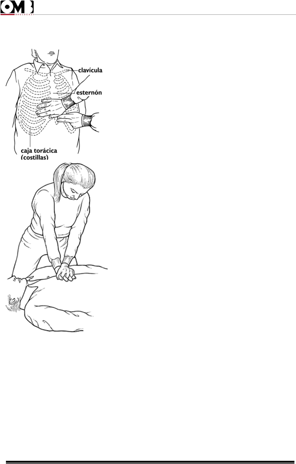
Step 5: BEGIN CHEST COMPRESSIONS.
Kneel next to the person. Use your fingers to locate the end
of the person's breastbone (sternum), where the ribs come
together. Place 2 fingers at the tip of the sternum. Place the
heel of the other hand directly above your fingers (on the side
closest to the person's face).
Place your other hand on top of the one that you just put in
position. Lock the fingers of both hands
together, and raise the fingers so they don't touch the person's
chest.
Straighten your arms, lock your elbows, and center your
shoulders directly over your hands.
Press down in a steady rhythm, using your body weight and
keeping your elbows locked. The force from each thrust
should go straight down onto the sternum, compressing it 1
to 2 inches. It may help to count "one and two and three and
four...," giving 1 downward thrust each time you say a
number. Lift your weight, but not your hands, from the chest
each time you say "and." Give 15 compressions.
After 15 compressions, give 2 full, slow breaths.
• Repeat the 15 compressions/2 breaths cycle 4 times (1 minute); then check again for signs of
circulation. If there are still no signs of circulation, continue to give chest compressions and
rescue breaths until help arrives or until signs of circulation are present and breathing is
restored.

FM Transmitter
EM 500 DIG PLUS
Technical Manual - v1.0 - April 2012
8
E
EL
LE
EC
CT
TR
RO
OC
CU
UT
TI
IO
ON
N
Otherwise the current will pass through the victim directly to you.
• If at all possible, turn off the source of electricity (i.e. light switch, circuit breaker, etc.) If this is
not an option, use non-conductive material such as plastic or dry wood to separate the source
of electricity from the victim.
• If the injuries appear serious or extensive, call to emergency number.
• Check the victim's vitals signs such as the depth of his breathing and regularity of his heart
beat. If either one is effected by exposure to electricity or if the victim is unconscious, begin to
perform CPR.
T
TR
RE
EA
AT
TM
ME
EN
NT
T
F
FO
OR
R
B
BU
UR
RN
NS
S
Continue treating victim for electrical shock.
Check for points of entry and exit of current.
Cover burned surface with a clean dressing.
Remove all clothing from the injured area, but cut around any clothing that adheres to
the skin and leave it in place. Keep the patient covered, except the injured part, since
there is a tendency to chill.
Splint all fractures. (Violent muscle contractions caused by the electricity may result in
fractures.)
Never allow burned surfaces to be in contact with each other, such as: areas between
the fingers or toes, the ears and the side of the head, the undersurface of the arm and
the chest wall, the folds of the groin, and similar places.
Transport the victim as soon as possible to a medical facility.
IN THE EVENT OF ELECTROCUTION DO
NOT RUSH TO ASSIST THE VICTIM UNTIL
YOU ARE CERTAIN THAT HE IS NO LONGER
IN CONTACT WITH ELECTRICITY.

FM Transmitter
EM 500 DIG PLUS
Technical Manual - v1.0 - April 2012
9
CONTENTS:
1.1 Introduction. . . . . . . . . . . . . . . . . . . . 10
1.2 Technical specifications. . . . . . . . . . . . . .11
1.3 Location of parts. . . . . . . . . . . . . . . . . .12
1.4 Installation. . . . . . . . . . . . . . . . . . . . . 14
S
Se
ec
ct
ti
io
on
n
1
1
I
IN
NT
TR
RO
OD
DU
UC
CT
TI
IO
ON
N

FM Transmitter
EM 500 DIG PLUS
Technical Manual - v1.0 - April 2012
10
1.1 Introduction.
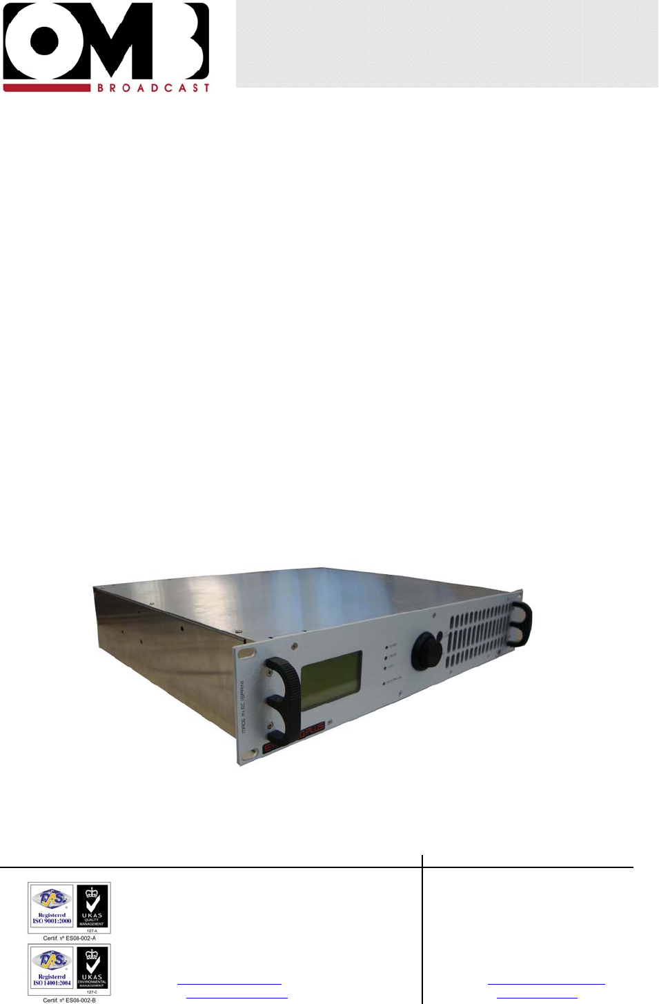
The EM 500 DIG PLUS transmitter is equipped with the most modern technology available, to provide
you with maximum performance at minimal performance cost, while fully conforming to technical
regulations. Flexibility, quality, compactness, and low electrical consumption make the devices in the
EM 500 DIG PLUS the best offered on the market today.
These are just a few of the advanced characteristics that make the EM 500 DIG PLUS truly unique:
• Super-compact size and reduced weight
• Low performance costs. The unique design reduces internal loss and allows the device to achieve
an extremely high yield – typically greater than 80% - minimizing electrical consumption and thus
decreasing performance costs.
• Sturdy modular construction. Reliable modular construction minimizes and facilitates maintenance
operations. In addition, it ensures a greater average time between failures, as well as ease of
maintenance.
• Easy to use and to configure. The transceiver uses a control interface, which is equipped with a
large LCD screen, a multifunction knob, and few other buttons. This allows the user to easily set
functions on the device, and to view the operating parameters in the blink of an eye.
• Nominal RF output power over the full FM range particularly stable against time. The output
power may be varied from a minimum level and the operating frequency includes the full FM range,
without retouching other parameters.
• Power section entirely modular and highly reliable.
• RF output stage has a reverse intermodulation figure lower than the standard bipolar
construction. Low enough to approach that of tube equipment, due to the MOS-FET design.
• Low level of dissipation. The reduction in internal loss and overall elevated yield minimize the
dissipation of heat; as a result, the devices in the EM 500 DIG PLUS perform well even in challenging
environmental conditions.
• Stable, reliable power supply. The entire line of transmitters integrates the use of power sources
with active power factor correction (PCF), as stipulated in recent regulations. As such, impact on the
electrical power source is minimal, resulting in greater reliability over the entire device.
• Easy diagnostics and easy-to-read parameters, thanks to a comprehensive metering and alarms
section on the LCD display. All parameters and alarms are easily accessible from remote posts via the
remote control input, which allows the user to change from stand-by to “on air” in a fraction of a second.
Upon request, an external controller can be provided for long range use of the device from an office or
from other service points.
• Compliance with the strictest regulations. This device was designed in full compliance with CCIR,
FFC, and other strict international regulations, as well as the recent, strict EC anti-magnetic noise
requirements. In addition, this device complies with EC and ETSI 302.018-2 v 1.1.2.1 (2006-03)
standards.

FM Transmitter
EM 500 DIG PLUS
Technical Manual - v1.0 - April 2012
11
1.2 Technical Specifications.
Frequency range 87.5 - 108MHz
FM Modulation
75kHz (adjustable) peak deviation
Mono 180kF3E
Stereo 256kF3E
Audio/MPX Input Level -3.5 to +12.5dBm @ 75kHz deviation
Audio Input Connectors XLR Female
AES/EBU digital input connector (optional) XLR Female, 110Ω balanced
Separation between channels (optional
stereo generator) 60dB
Aux channel input level (RDS/SCA) 7.5 kHz deviation: -12.5 to 3.5dBm
2 kHz deviation: -24 to -8 dBm
Aux channel input impedance 10kOhm
Modulation distortion 7.5 kHz deviation: <0.05%, 0.02% typical
2 kHz deviation: <0.2%, 0.05% typical
Mono S/N ratio 30 to 20000Hz: >76dB, 86dB typical
CCIR: >75dB, 81dB typical
Stereo S/N ratio 30 to 20000Hz: >72dB, 77dB typical
CCIR: >68dB, 72dB typical
Audio channels bandwidth 30 to 15000Hz ± 0.1dB
Pre-emphasis time constant Selectable, 25/50/75 microseconds
Nominal RF output power 500W
Consumption 713 VA (@ 500 W output power)
Transmitter tuning steps 10/100kHz
Output power ALC stability ±3%
Harmonics and spurious emissions <80dBc
RF output impedance 50Ω
RF output connector N type
RF sampler connector BNC type
Power supply 110 - 230Vac ± 15%; 50/60Hz
Operating temperature range 0 to 40ºC recommended
-10 to 55ºC max
Relative humidity up to 95% not condensed

FM Transmitter
EM 500 DIG PLUS
Technical Manual - v1.0 - April 2012
12
1.3 Location of parts.
1.3.1 Front panel description.
The front panel of the EM 500 DIG PLUS is shown in the next picture:
Figure 1.1: EM 500 DIG PLUS Front Panel
The elements shown in the previous figure are described next:
1. Control Panel. Allows the user to set device functions and to view and set operating parameters. It is
composed of the following:
• Liquid crystal display (LCD) – a graphics display that shows the operating parameters and functions
selected via the multifunction knob.
• ALARM indicator light (red) – this LED lights up in red if an alarm event occurs (e.g., output power or
modulation too low).
• LIMITER indicator light (red) – this LED lights up in red to indicate that the maximum deviation limiter
has activated due to an audio signal that is too high.
• ON indicator light (yellow/green) – this LED lights up two ways:
• It lights up in yellow when the device is on stand-by
• It lights up in green when the device is in operation (powered up).
• LOCK indicator light (green) – this LED lights up in green to indicate that the internal frequency
synthesizer is locked on the set operating frequency.
• Multifunction knob (encoder) – allows the user to navigate the command menu in various ways:
• If turned – selects the various functions/operations for the device, or the parameter values to be set.
• If briefly pressed (like a button) when inside a menu – activates the option currently selected.
• ESCAPE button – while navigating through a menu, pressing this button will return the user to the
previous level.
• ON/STAND-BY button – starts the device or puts it on stand-by.
2. Handles. Allow the user to easily pick up the device to remove it from or insert it into a mobile rack.
1
2 2
FM Transmitter
EM 500 DIG PLUS
Technical Manual - v1.0 - April 2012
13
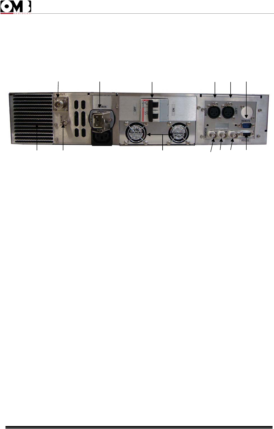
1.3.2 Rear panel description.
The rear panel of the EM 500 DIG PLUS is shown in the next picture:
Figure 1.2: EM 500 DIG PLUS Rear Panel
The elements shown in the previous figure are described next:
1. Antenna output socket/flange (RF OUTPUT) – this socket/flange is connected to an FM
broadcasting antenna that can tolerate the transmitter’s nominal power.
2. Power socket or cable – used to connect to a mains supply.
3. General power switch (POWER ON) – allows the user to turn the general system power on and off.
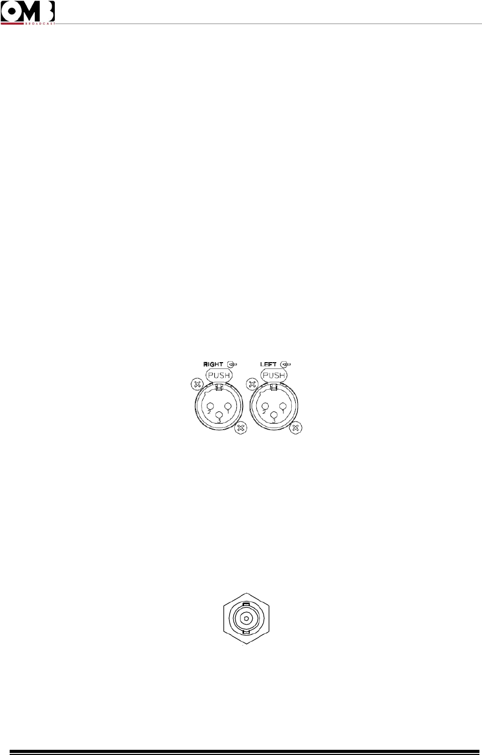
4. RIGHT – balanced input (female XLR) for modulation of the right audio channel. This input can also
accept a mono signal for monophonic transmissions.
5. LEFT – balanced input (female XLR) for modulation of the left audio channel.
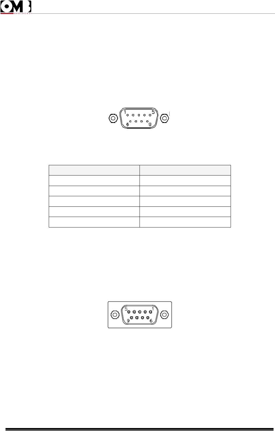
6. REMOTE control input – this 9-pin SUBD connector allows the user to remotely control the device
or to perform other functions via a suitable interface.
7. RS232 serial programming port – this female RS 232 Sub-D9 port with inverted cable allows the
user to control the transmitter via a computer or an external point-to-point control device.
8. MPX – externally created broadband stereo composite modulating signal input (BNC-type
unbalanced connector with grounding shield).
9. AUX – auxiliary modulating channel input (RDS/SCA) at low frequency on a 20-100 KHz band (BNC-
type unbalanced connector with grounding shield) for connection to an RDS encoder.
10. MODULATION MONITOR socket – BF modulation output socket to be used as a monitor, for
synchronization of the RDS encoder, or broadcast retransmission (BNC-type connector).
11. Power supply fans.
12. Posterior RF MONITOR input – BNC-type connector for sourcing the low level RF signal. The
signal attenuation is 57 dB.
13. Heat shink.
13 12 11 10 9 8 7
1 2 3 4 5 6

FM Transmitter
EM 500 DIG PLUS
Technical Manual - v1.0 - April 2012
14
1.4 Installation
1.4.1 Check the supplied parts
Before using your transmitter, ensure that the following parts are included in the package:
• The transmitter
• The user manual
• A power cable supplied with a suitable connector
If any parts or missing or damaged, contact your supplier at once.
1.4.2 General safety rules
Warning! In order to prevent serious damage to objects or people, the following rules must be
strictly followed.
• Although no special instruments are required in most cases, the device should be installed by skilled
personnel only. To make best use of the device and prevent damage to the unit, it is necessary to
comply with the instructions outlined in this manual.
Should doubts or technical problems arise during the installation procedure, it is strongly recommended
that you contact OMB or a local agent/dealer.
• Should technical problems or doubts of any kind arise during installation, OMB would be happy to
provide qualified technical assistance. Technical intervention by personnel not authorized by OMB
should not be performed.
• As a rule, the user should not access the inside of the device. Tampering with the factory settings
renders our warranty null and void, and may also affect the device’s performance, causing costly
damage.
• No adjustments or internal calibrations are required for normal operations. The device must be
properly grounded and must be used with all the covers closed in order to prevent electrical shocks and
to fully comply with EC, EMI, and other safety regulations.
• Never touch the inside of the device without first disconnecting it from the mains. AC, DC, and
radiofrequency voltages are present inside the device and can be dangerous when the covers are
removed.
• Do not operate the device without the covers properly screwed into place. Using an open transmitter
may be dangerous to objects or people. In addition, if the top cover is removed, this may cause the
device or other electronic measurement instrument to perform incorrectly due to the elevated RF fields.
1.4.3 Placement of the device
- Choosing the proper room and placement
• Install the device in a dry, sheltered, well-ventilated room away from dust, moisture, insects, and
rodents (mice).
• Room size should be such that the device can be placed in an upright position, and that technical
personnel can easily perform routine or extraordinary maintenance. Evaluate the minimum size
according to the power supplied by your model, taking into account that a volume of 2.5 x 2.2 m in

FM Transmitter
EM 500 DIG PLUS
Technical Manual - v1.0 - April 2012
15
height is required for a transmitter with 1 KW of power, and that no other transmission or auxiliary
devices should be present in the vicinity.
• Place the apparatus as close as possible to the antenna, in order to prevent excessive power loss in
the cables. If this is not feasible, use antenna cables with low loss and suitable cross-section.
• Vents in the walls and any other openings must be fitted with metal gratings to keep rodents and
insects out, and must be equipped with a dust filter. Make absolutely sure that no water can seep
through the vents, the air exhaust duct, or the antenna cable grommet. Also confirm that the floor is not
at risk of flooding during heavy rainfall.
- Climatic conditions
• In order to achieve optimum performance in terms of power, life span, etc., the ideal room temperature
should range between 5°C and +25°C. As a general rule, the useful life span of the device may be
halved by a 10°C increase in room temperature, should the temperature exceed 30°C. The pre-set
over-temperature alarm will activate when the limit of 45°C is exceeded. It is advisable to hang a
minimum/maximum thermometer on the wall to indicate variations in temperature.
• The room must be ventilated to ensure that the temperature never exceeds 35°C. Such conditions can
NOT generally be met when the exhaust cooling air is not pushed outside and is instead fed back into
the room. This is also occurring if more than one device is installed in the same location. An efficient
ventilation system with air exchange is thus required in the room. For your reference, the air flow rate
required for proper functioning of a 1 KW transmitter must be at least 500 cubic meters per hour.
Evaluate this element in proportion to the power supplied by the model you are installing.
• If the device is placed on a rack, the rear door of the rack can not usually be secured. If the system
must be completely enclosed, a ventilation and air removal system must be created. To encourage air
flow, a flange can be installed at the ventilation outflow, to which a hot air discharge conduit can be
connected to the exterior. In this case, it is important to remember that the transmitter’s internal fans are
low pressure units and that it is fundamental for an exhaust fan to be installed on the air discharge
conduit.
• The best solution is to keep the room at 20-25°C. Thermal insulation and effective ventilation via a fan
controlled by a thermostat generally present the most advantageous solution.
• Excessive concentrations of moisture and/or dust in the air or in the room may cause a condensation
build-up in the transmitter. If the system is periodically switched on and off, this can trigger destructive
electric arcs and short circuits, and thus cause damage that is not covered by warranty.
- Electrical conditions
• The mains capacity must be proportionately designed to adequately support the device’s power
consumption (including a sufficient safety margin).
• The power supply nominal range comes from 100 to 265 VAC (nominal voltage single-phase 230
VAC).
• Mains fluctuations and electrical discharges due to weather or nearby industrial machinery may cause
significant trouble, especially in mountain areas and in locations close to industrial areas.
• In such cases, it is advisable, if not indispensable, to install a protector, an insulating transformer, or
possibly an electromechanical mains voltage regulator.

FM Transmitter
EM 500 DIG PLUS
Technical Manual - v1.0 - April 2012
16
• Even though the mains regulator allows for a wide incoming voltage range, it is important to avoid
operating using high impedance mains lines in proximity to the lowest permitted AC limit: if the line falls
below a given value while fully loaded, the control circuit for the lowest AC limit may trigger a very
dangerous oscillating on/off cycle. In such cases, we recommend using a stabilizer on the external line.
1.4.4 Wiring the device
This section describes the minimum connections required to place the transmitter in operation.
- Wiring into the antenna
Connect the RF OUT connector to the antenna or to the next RF amplifier via a high-quality 50 Ohm
shielded coaxial cable equipped with the appropriate connectors.
It is indispensable that only low-loss cables be used when connecting directly to the antenna: in such
cases, Celflex or another similar ½" cable is recommended. Larger cables must be connected using
flexible terminal ends from the smallest section, in order to avoid mechanical stress on the output
connector.
It is very important to ensure that the antenna, cables, and connectors have the correct
impedance and are appropriate to the transmitter’s nominal power level.
The antenna must be suitable for FM broadcasting and able to resonate at the operating
frequency with the minimum possible SWR.
The antenna must be grounded via a copper braid of suitable cross-section to prevent lightening
or static electricity from reaching the amplifier through the antenna cable.
- Connection to modulation signals
Connect the LEFT and RIGHT modulation inputs, or the MPX input alternatively, based on your desired
operating mode (monophonic or stereophonic) and the type of source being used (mono, stereo, or
multiplex signal).
The MPX connector is internally connected in parallel to the RIGHT connector. As such, if the
MPX connector is in use, the simultaneous connection of signals to the LEFT and RIGHT
connectors is not possible. Again in this case, the highest impedance position is 5 KOhm.
- Wiring into the mains
1) Verify that the rear power switch is turned off; if it is not off, do so now.
2) Ground the system.
3) According to your model, connect the power cable or the device’s cable to a suitable single-phase
input (230VAC nominal voltage).
Before connecting the power, ensure that it is appropriate and is able to support the
consumption required by the transmitter model you intend to use.
Your transmitter should not be used when near the lower voltage limit with high-impedance
lines: if the line voltage falls below a certain limit at full load, the low voltage sensor circuit could
trigger a continuous, extremely dangerous on/off cycle. In such case, install an external voltage
stabilizer.
In order to ensure proper operation and comply with safety regulations, proper grounding is
required. Use the yellow/green lead in the power cable. The cable neutral lead is blue. Never
connect the earth to the mains neutral lead.
FM Transmitter
EM 500 DIG PLUS
Technical Manual - v1.0 - April 2012
17
Use only the power supply cable supplied with the transmitter. For cable extensions, sections of
sufficient and appropriate length are recommended.
Never turn the device on without an antenna connection, even when in stand-by.
- Connection to the auxiliary modulation (optional)
Where necessary, an auxiliary RDS or SCA modulation source can be connected to the AUX input.
- Parallel port for remote control (optional)
Where necessary, connections can be made to the REMOTE parallel port. Various lines are located in
this port for simple, direct control of the transmitter via a male DB9 connector.
Connection of the pins is outlined in the following table:
Number Connection
1, 5 and 8 Ground
2 On the air signal
3 Direct power
6 Disable RF
7 Alarm
- Connection to the RS232 port (optional)
Where necessary, connections can be made to the RS232 port. This port manages Tx, Rx, and related
return data signals via a RS232 standard without any “handshake” signal.
The above signals are inversely connected to the port; as such, a simple pin-to-pin type serial cable is
sufficient, directly connected to suitable connectors, usually a female DB9 or DB25 on the PC port and
a male DB9 connector to the transmitter. The applicable communication software is also required.
- Never connect the cable if the PC or the transmitter are turned on.

FM Transmitter
EM 500 DIG PLUS
Technical Manual - v1.0 - April 2012
18
CONTENTS:
2.1 Audio Operation Modes . . . . . . . . . . . . . 19
2.2 Basic Operations . . . . . . . . . . . . . . . . . 22
2.3 Menu and Navigation Commands . . . . . . . . 30
2.4 Description of the menu . . . . . . . . . . . . . 33
2.5 Troubleshooting . . . . . . . . . . . . . . . . . 55
S
Se
ec
ct
ti
io
on
n
2
2
O
OP
PE
ER
RA
AT
TI
IO
ON
N

FM Transmitter
EM 500 DIG PLUS
Technical Manual - v1.0 - April 2012
19
2.1 Audio Operation Modes.
This section describes how to select the various available operating modes, and how to make audio
connections according to your requirements.
The transmitter is equipped with numerous characteristics specific to high-fidelity systems; as such, it
should be connected to modulating signals with the same care as a Hi-Fi system, avoiding ground loops
as much as possible. Under these conditions, you will obtain optimal performance.
According to the operating mode and type of modulation source available, you can connect to the
modulation inputs in various ways:
• Monophonic transmission from an audio signal, via the main mono channel
• Monophonic transmission from a stereophonic audio signal, using the internal stereo encoder
• Stereophonic transmission from a stereophonic audio signal, using the internal stereo encoder
• Monophonic or stereophonic transmission from an external encoder or radio link receiver.
The device is also able to transmit an auxiliary signal (RDS or SCA), connected to the rear AUX input
as described below.
2.1.1 Mono transmission from a mono signal
1) Connect the RIGHT connector to the monophonic audio signal. Connection to the LEFT input is not
necessary.
2) Using the SETUP menu, set the modulation mode to Mono.
3) Confirm or change pre-emphasis according to the local standard.
2.1.2 Mono transmission from a stereo signal
1) Connect the RIGHT connector to the right audio channel.
2) Connect the LEFT connector to the left audio channel.
3) Using the SETUP menu set the modulation mode to Mono L+R.
4) Confirm or change pre-emphasis according to the local standard.
2.1.3 Monophonic or stereophonic transmission from a multiplex signal
If you wish to use a multiplex signal (MPX) originating, for example, from an external encoder or a radio
link receiver, follow the steps below:
1) Connect the multiplex signal to the MPX connector. The multiplex signal is already pre-emphasized;
as such, using the MPX input, the filtering and stereo encoding stages are skipped and the signal will
not be further preemphasized.
2) Using the SETUP menu, set the modulation mode to Mpx.
Selecting the preemphasis according to the local standard is not required, as it is irrelevant in this
mode. However, it is recommended that this be done anyway.
If the length of the cable delivering the signal to the MPX connector is only a few meters long, a 50 Ohm
(RG58) cable can be used. If the distance is greater, a 75 Ohm (RG59) or 92 Ohm (RG62) cable should
be used.
2.1.4 Connection to LEFT, RIGHT, or MPX modulation connectors
FM Transmitter
EM 500 DIG PLUS
Technical Manual - v1.0 - April 2012
20
The EM 500 DIG PLUS supports both balanced and unbalanced audio signals according to the
connection that is made in the three LEFT and RIGHT XLR connector contacts. The input impedance
for these contacts is pre-set at the factory at 10 KOhm resistivity (5 KOhm for unbalanced connections),
which can be decreased to 600 Ohm if necessary, as explained further ahead.
Normally, an XLR audio input with balanced connection is used for connection to the balanced output of
a professional mixer.
Alternatively, an unbalanced connection can be used, and is useful for output connections on
inexpensive devices, without a perceptible degradation in the audio signal.
Alternatively to connection to the LEFT e RIGHT connectors, an externally created multiplex signal can
be connected to the MPX connector. In this case, connection should not be made to the LEFT and
RIGHT connectors.
The MPX connector is internally connected in parallel to the RIGHT connector. As such, if the
MPX connector is in use, the simultaneous connection of signals to the LEFT and RIGHT
connectors is not possible. In such case, the highest impedance position is 5 KOhm.
- Balanced connection to the LEFT and RIGHT connectors
The output for a mixer or any other audio processor that drives a transmitter with a balanced coaxial
cable should be connected at pin 3 (-) and pin 2 (+). The cable shield, connected to the ground of the
audio driver device, must be connected to pin 1.
Balanced connection offers the greatest advantages. For example, cables connected to a source can
greatly exceed 100 meters in length.
- Unbalanced connection to the LEFT and RIGHT connectors
For driving with an unbalanced signal, input pin 3 must be short-circuited with the ground and the shield
to pin 1, while the signal must go to pin 2. In such case, the highest impedance selection will be 5
KOhm rather than 10 KOhm.
2.1.5 Connection to the MPX input
Connect an externally created multiplex signal to the MPX input using a suitable encoder.
If the length of the cable delivering the signal to the MPX connector is only a few meters long, a 50 Ohm
(RG58) cable can be used. If the distance is greater, a 75 Ohm (RG59) or 92 Ohm (RG62) cable should
be used.
- Checking the pilot tone in stereophonic transmission
FM Transmitter
EM 500 DIG PLUS
Technical Manual - v1.0 - April 2012
21
Where the internal stereo encoder is used, the level of the stereo driver tone, which is usually set
internally at 9-10% of the modulation (from -21 to -20dB) corresponding to the standard established
deviation of 7 – 7.5 kHz, cannot be changed externally.
Where the stereo modulation signal is externally generated by a separate stereo encoder, the driver
tone must be measured in the absence of audio modulation and all other auxiliary signals, as described
below:
1) Disconnect all signals from the external stereo encoder input, and any RDS or SCA signals.
2) Select the VIEW - AUX menu and confirm that the driver tone is now the only available signal. The
standard level is as indicated above, 9-10% (-21 to -20dB), and can be consequently adjusted on the
external stereo encoder as required.
3) Reconnect the previously disconnected signals.
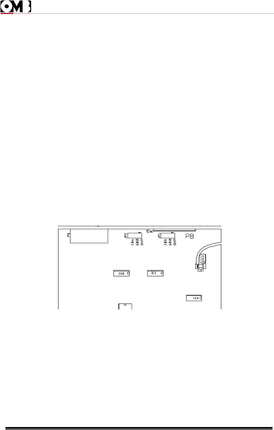
2.1.6 Changing the input impedance
As previously explained, the input impedance on the modulation inputs can be changed. Selection of
the input impedance is one of the very few settings that can only be changed internally, as follows:
1) Disconnect the mains.
2) Unscrew the screws that hold the top cover in place (16 or more cross-head screws will require
removal, depending on the model).
3) Remove the top cover and store it in a safe place.
4) Identify the input card.
5) The input impedance is easily set using the JP1 e JP2 jumpers found on the input card, immediately
after the input connectors as illustrated in the design. The selectable impedance values are serigraphed
on the printed circuit board.
6) Place the top cover back on the transmitter, ensuring that all the screws are correctly screwed into
place.
2.1.7 Pre-emphasis
The low frequency audio signals of mono and stereo channels must be properly “pre-emphasized”. The
standard pre-emphasis is 50 or 75 μs, the first value usually being the one selected during manufacture.
Confirm that this value is appropriate in your country: it is the standard value for all countries in Europe,

FM Transmitter
EM 500 DIG PLUS
Technical Manual - v1.0 - April 2012
22
most of the Pacific regions, and some countries in South America. However, the North American FCC
standards require 75 μs.
To make changes to the pre-emphasis, use the SETUP menu.
2.1.8 Operating with the RDS and SCA encoders
In addition to the aforementioned operating modes, this device is able to transmit an auxiliary signal
(RDS or SCA) connected to the rear AUX terminal as follows:
1) Connect the AUX terminal to the RDS or SCA encoder output.
2) If the internal stereo encoder is used, connect the MODULATION MONITOR output to the “driver
tone” synchronization input on the RDS encoder (where available).
3) Using the SETUP - AUX SENS menu, change the channel input sensitivity and, where necessary,
the external generator level so as to obtain the required deviation. For RDS encoders, a reading of -
11.5 dB or 2kHz is the standard modulation value.
4) Modulation and deviation can be viewed on the STATUS screen, in addition to any other multiplex
signals available at that time.
If the length of the cable delivering the signal to the AUX terminal is only a few meters long, a 50 Ohm
(RG58) cable can be used. If the distance is greater, a 75 Ohm (RG59) or 92 Ohm (RG62) cable should
be used. The same is valid for connection to the MODULATION MONITOR input.
2.2 Basic Operations.
2.2.1 Initial start-up and basic adjustments
The first time the device is turned on, it is important to perform basic adjustments (frequency, output
power, modulation, etc.) and verify that they are functioning correctly (e.g., reflected power) via the
commands menu. This section explains how to perform these adjustments.
The transmitter stores in its memory the operating mode in which it was working before the
power supply was turned off or a mains failure took place. Therefore, before continuing, it is
important to ensure that it is connected to a load that is able to support the maximum
deliverable power.
Operating the transmitter without an antenna, or when the antenna is improperly connected,
may cause damage that is not covered by the warranty, particularly during the final stage of
transmission.
If turning the transmitter on places it directly in operation (rather than on stand-by), we
recommend that the ON/STAND-BY button be pressed to place the transmitter on stand-by while
making adjustments.
FM Transmitter
EM 500 DIG PLUS
Technical Manual - v1.0 - April 2012
23
Proper adjustment of the parameters should be made so as to conform to local regulations;
such conformity is the full responsibility of the user.
If the device is left on the SETUP menu without receiving a command, the display will automatically
return to the STATUS screen under the VIEW menu.
1) Ensure that all installation conditions are met, and that all the connections described have been
made. You can connect a suitable dummy load to the transmitter’s RF output instead of the antenna.
2) Turn on the device via the rear power switch. For a few seconds, the OMB logo will appear on the full
screen; after this, the default screen will be displayed; the bottom of the default screen will show the two
main menus, VIEW and SETUP.
3) At this point, two conditions are possible:
• The transmitter begins to operate (including possible powering up) – the display turns on, and the
ON LED lights up in green. In such case, it is recommended that the basic settings be made, turning the
transmitter on stand-by. To do so, press the ON/STAND-BY button. Ensure the ON LED lights up in
yellow and skip directly to step 4).
• The transmitter goes to stand-by – the display turns on, and the ON LED lights up in yellow. At this
point, proceed to the next step.
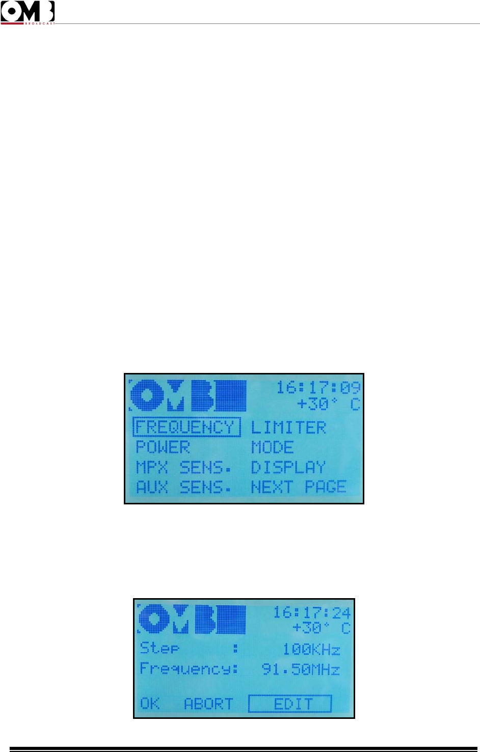
4) Turn the knob to select the main SETUP menu, and press briefly to confirm. The first of the three
pages comprising the SETUP menu will appear:
2.2.2 Operating frequency
5) Ensure that the FREQUENCY sub-menu is selected; otherwise, turn the knob to select it.
6) Press the knob to access the sub-menu. The following screen will appear:
FM Transmitter
EM 500 DIG PLUS
Technical Manual - v1.0 - April 2012
24
7) Ensure that the EDIT option is selected; otherwise, turn the knob to select it, then press to confirm.
8) A value will be indicated after Step (frequency steps).
9) Turn the knob until you select the frequency step required to exactly set the required operating
frequency, then press the knob to confirm.
Normally, it is sufficient to leave it at 100KHz (e.g., operating frequency of 91.50 MHz). Otherwise, if the
operating frequency is defined at a step lower than 100 KHz (e.g., operating frequency of 97.850 MHz),
you will need to select the 10 KHz step.
10) A value will be indicated after Frequency. Turn the knob until you reach the exact operating
frequency desired,then press the knob to confirm.
11) OK will be highlighted. Three choices are now available:
o If the parameters set are correct – skip directly to step 12) to confirm the settings.
o If the parameters set are all incorrect – cancel all settings by turning the knob until ABORT is
highlighted, then skip to step 12).
o If a slight adjustment to the parameters is required – turn the knob until EDIT is highlighted, then
return to step 8.
12) Press the knob to confirm. You will return to the page indicated in step 3).
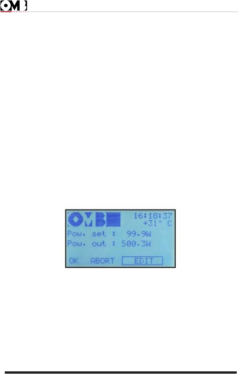
2.2.3 RF output power
13) Turn the knob until the POWER sub-menu is selected, then press to confirm. The power adjustment
screen will appear:
14) Ensure that the EDIT option is selected; otherwise, turn the knob to select it, then press to confirm.
15) A value will be indicated after Pow. Set:
16) Turn the knob until the desired power is set, then press the knob to confirm.
17) Okay will be highlighted OK. Three choices are now available:
o If the parameters set are correct – skip directly to step 18) to confirm the settings.
o If the parameters set are all incorrect – cancel all settings by turning the knob until ABORT is
highlighted, then skip to step 18).
o If a slight adjustment to the parameters is required – turn the knob until EDIT is highlighted, then
return to step 15).
FM Transmitter
EM 500 DIG PLUS
Technical Manual - v1.0 - April 2012
25
18) Press the knob to confirm. You will return to the page indicated in step 3).
If the device is currently in operation (green ON LED lit up), the Pow. out: indicator will show the
power currently supplied.
Otherwise, with the device on stand-by (yellow ON LED lit up), the indicator will remain at 0.0W.
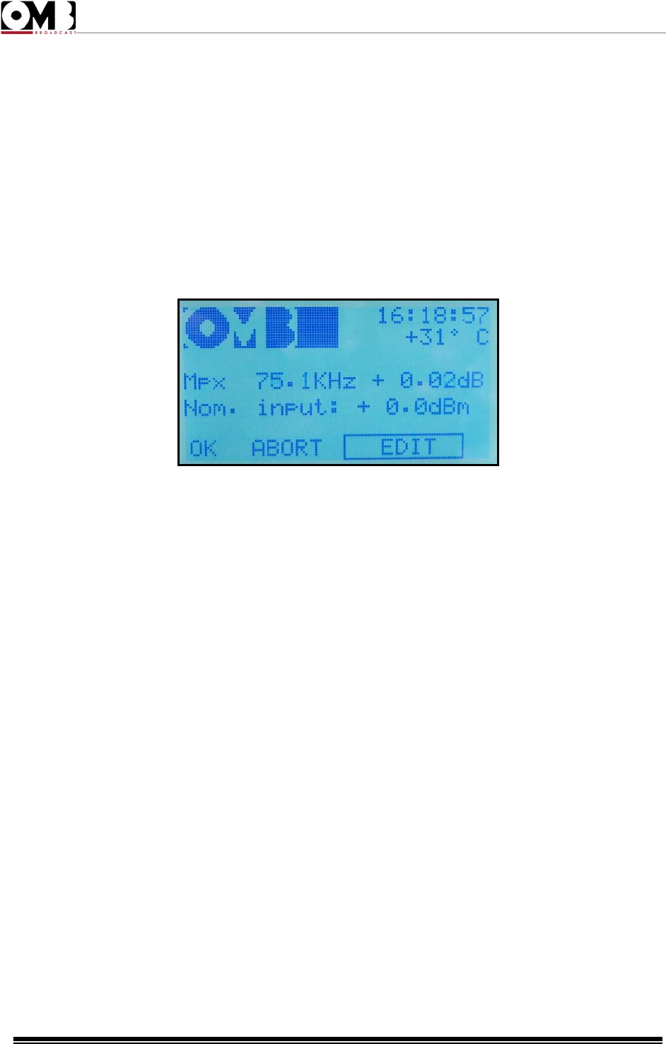
2.2.4 Modulation sensitivity
19) Turn the knob until the MPX SENS. sub-menu is selected, then press the knob to confirm.
20) The modulation sensitivity adjustment screen will appear:
21) Ensure that the EDIT option is selected; otherwise, turn the knob to select it, then press to confirm.
22) A value will be indicated after Nom. Input, normally pre-defined at +0.0 dBm.
23) Turn the knob to adjust the value based on the modulation level used. The peak deviation indicated
by Mpx, expressed in KHz, will consequently be changed. Note that, to the right of the deviation, the
value of the modulating signal will be indicated, as compared to the nominal value set.
24) Ensure that the measured peak deviation does not exceed local regulations, then press the knob to
confirm the setting.
25) OK will be highlighted. Three choices are now available:
o If the parameters set are correct – skip directly to step 26) to confirm the settings.
o If the parameters set are all incorrect – cancel all settings by turning the knob until ABORT is
highlighted, then skip to step 26).
o If a slight adjustment to the parameters is required – turn the knob until EDIT is highlighted, then
return to step 22).
26) Press the knob to confirm. You will return to the page indicated in step 3).
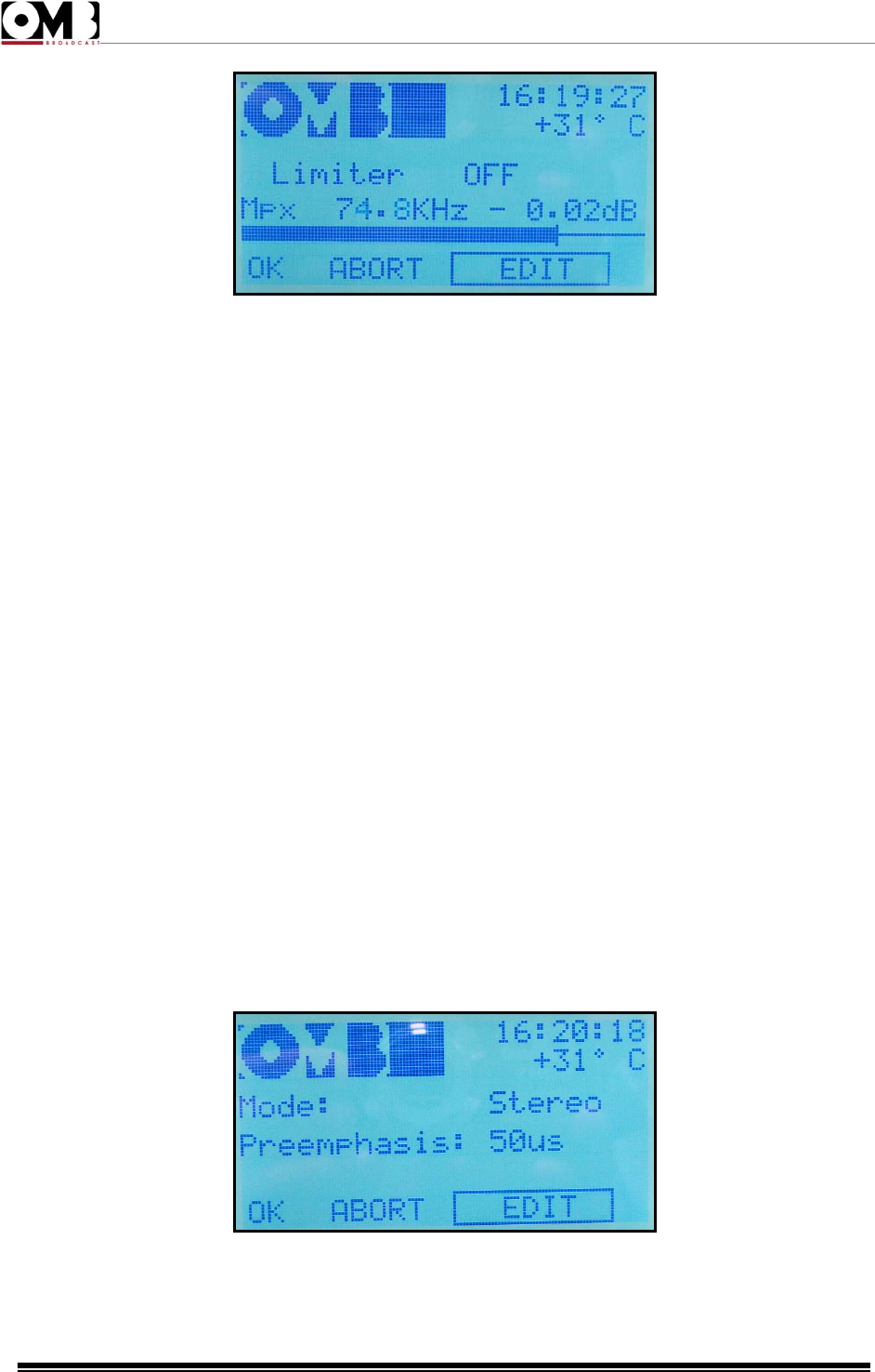
2.2.5 Modulation limiter
27) Turn the knob until the LIMITER sub-menu is selected, then press the knob to confirm.
28) The modulation limiter adjustment screen will appear:
FM Transmitter
EM 500 DIG PLUS
Technical Manual - v1.0 - April 2012
26
29) Ensure that the EDIT option is selected; otherwise, turn the knob to select it, then press to confirm.
30) A value will be indicated after Limiter. This indicator is normally followed by OFF or by the limiter
intervention value, expressed in dB, in reference to a deviation of 75 KHz.
31) Turn the knob to set the desired value (0 dB = limiter intervention of 75 KHz), then press the knob to
confirm.
32) OK will be highlighted. Three choices are now available:
o If the parameters set are correct – skip directly to step 33) to confirm the settings.
o If the parameters set are all incorrect – cancel all settings by turning the knob until ABORT is
highlighted, then skip to step 33).
o If a slight adjustment to the parameters is required – turn the knob until EDIT is highlighted, then
return to step 30).
33) Press the knob to confirm. You will return to the page indicated in step 3).
When the limiter begins to intervene, the modulation distortion increases. As such, the modulation
sensitivity should be adjusted so the limiter intervenes sporadically. Using this approach, its operation is
generally imperceptible.
When the limiter activates, the LIMITER LED lights up in red.
2.2.6 Transmission modes (mono/stereo) and pre-emphasis
34) Turn the knob until the MODE sub-menu is selected, then press the knob to confirm.
35) The transmission mode settings screen will appear:
36) Ensure that the EDIT option is selected; otherwise, turn the knob to select it, then press to confirm.
FM Transmitter
EM 500 DIG PLUS
Technical Manual - v1.0 - April 2012
27
37) A value will be indicated after Mode. This indicator is normally followed by the operating mode
(mono, stereo, mono L+R, or Mpx).
38) Turn the knob until the desired setting is selected, based on your needs, then press the knob to
confirm.
39) A value will be indicated after Pre-emphasis. Turn the knob until the pre-emphasis value for your
geographical region is selected (50 microseconds in Spain), then press the knob to confirm the value.
40) OK will be highlighted. Three choices are now available:
o If the parameters set are correct – skip directly to step 41) to confirm the settings.
o If the parameters set are all incorrect – cancel all settings by turning the knob until ABORT is
highlighted, then skip to step 41).
o If a slight adjustment to the parameters is required – turn the knob until EDIT is highlighted, then
return to step 37).
41) Press the knob to confirm. You will return to the page indicated in step 3).
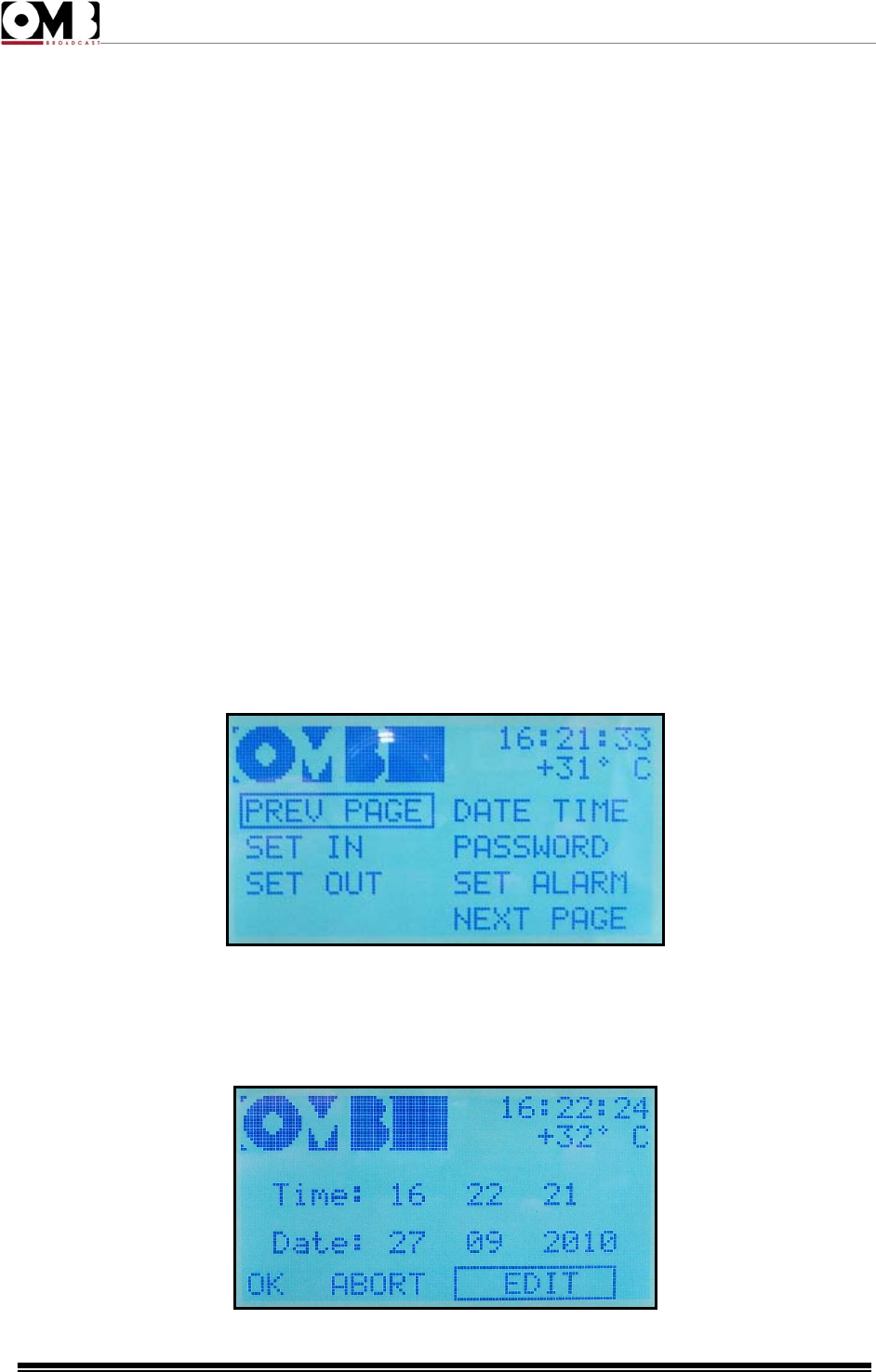
2.2.7 System date and time
Setting the date and time is important because it allows the transmitter to keep track of events (alarms,
etc.) that occur while the transmitter is operating. Set the date and time as follows:
42) Turn the knob until the NEXT PAGE sub-menu is selected, then press the knob to confirm. The
display will indicate the second page of the SETUP menu:
43) Turn the knob until the DATE TIME sub-menu is selected, then press the knob to confirm.
44) The date and time settings screen will appear:

FM Transmitter
EM 500 DIG PLUS
Technical Manual - v1.0 - April 2012
28
45) Ensure that the EDIT option is selected; otherwise, turn the knob to select it, then press to confirm.
46) The hour will be indicated after Time. Turn the knob and adjust the current hour, then press the
knob to confirm.
47) The minute will be indicated. Turn the knob to adjust the current minute, then press to confirm.
48) The second will be indicated. Turn the knob to adjust the current second, then press to confirm.
49) The day of the month will be indicated after Date. Turn the knob to set the current day, then press to
confirm.
50) The month will be indicated. Turn the knob to set the current month, then press to confirm.
51) The year will be indicated. Turn the knob to set the current year, then press to confirm.
52) OK will be highlighted. Three choices are now available:
o If the parameters set are correct – skip directly to step 53) to confirm the settings.
o If the parameters set are all incorrect – cancel all settings by turning the knob until ABORT is
highlighted, then skip to step 53).
o If a slight adjustment to the parameters is required – turn the knob until EDIT is highlighted, then
return to step 46).
53) Press the knob to confirm. You will return to the SETUP menu screen indicated in step 42).
2.2.8 Changing from stand-by to full operation
The transmitter is thus programmed with the basic parameters. You can now return to the default
screen by pressing the ESCAPE button. Of course, you may now need to adjust other parameters,
according to your requirements (e.g., modulation of the auxiliary RDS/SCA signal.
Once you are sure that you’ve correctly programmed all the parameters, you can place the transceiver
in full operation by pressing the ON/STAND-BY button. Ensure that the ON LED is lit up in green.
If the red ALARM indicator light appears, this means that an alarm event has occurred. When
this happens, check the type of alarm on the display, refer to the error table, and solve the
problem.
2.2.9 Checking parameters
We recommend that all the operating parameters be verified the first time that the transceiver is placed
in full operation, via the VIEW menu. To access this menu from the default screen:

FM Transmitter
EM 500 DIG PLUS
Technical Manual - v1.0 - April 2012
29
54) Turn the knob to select the main VIEW menu, then press to confirm.
55) The first page composing the VIEW menu will appear:
56) Verify that all parameters are correct, in particular:
o Direct and reflected power, via the STATUS sub-menu.
o Modulation, via the L/R and MPX GRAPH sub-menus.
o Operating frequency, mono/stereo mode, and pre-emphasis, via the SYSTEM sub-menu.
o Internal temperatures, via the TEMPERAT. sub-menu.
In addition, a spectrum analysis must be performed to ensure that no spurious emissions are generated
due to internal or external reasons (e.g., inverse intermodulation in the final stage).
If the reflected power exceeds 10% of the direct power, you will not be able to increase the
output power beyond a certain value due to an excessive SWR (standing wave ratio). Where this
occurs, the antenna system must be checked with a view to minimizing the reflected power.
If the red ALARM indicator light appears, this means that an alarm event has occurred. When
this happens, check the type of alarm on the display, refer to the error table, and resolve the
problem.
While in normal operation, we recommend that you leave your device on the STATUS sub-menu, found
under the main VIEW menu.
If you leave the device in the main SETUP menu, after a period, the timer will automatically select the
STATUS sub-menu under the main VIEW menu in order to avoid programming accidental settings.
2.2.10 Changing from full operation to stand-by and vice-versa
During normal operation, you can place the transmitter in stand-by by pressing the ON/STAND-BY
button. The device is on stand-by when the ON LED changes from green to yellow.
To perform the reverse operation, press the ON/STAND-BY button again. The ON LED will light up in
green.
2.2.11 Turning off the transmitter
To completely deactivate the device (for maintenance, etc.), we recommend that you first put it on
stand-by, as described above, and then completely turn off the device via the general power switch.
FM Transmitter
EM 500 DIG PLUS
Technical Manual - v1.0 - April 2012
30
2.3 Menu and Navigation Commands.
To view the device’s operating parameters, and to set parameters according to your requirements, you
will need to navigate the commands menu shown on the LCD display. You can navigate the menu
using:
• The multi-function knob.
• The ESCAPE button.
2.3.1 Multifunction knob
The multifunction knob is used to select the various menus that allow you to view or set the device’s
parameters and functions. It can be used in a variety of ways:
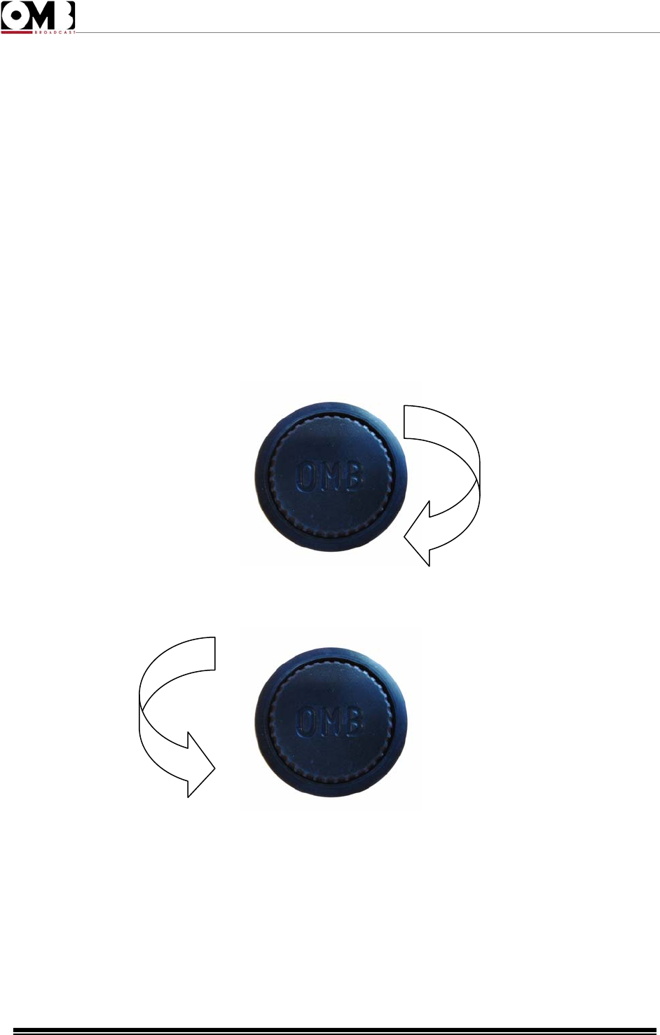
• When turned clockwise, it shows the next menu (or next option).
• When turned anti-clockwise, it shows the previous menu (or previous option).
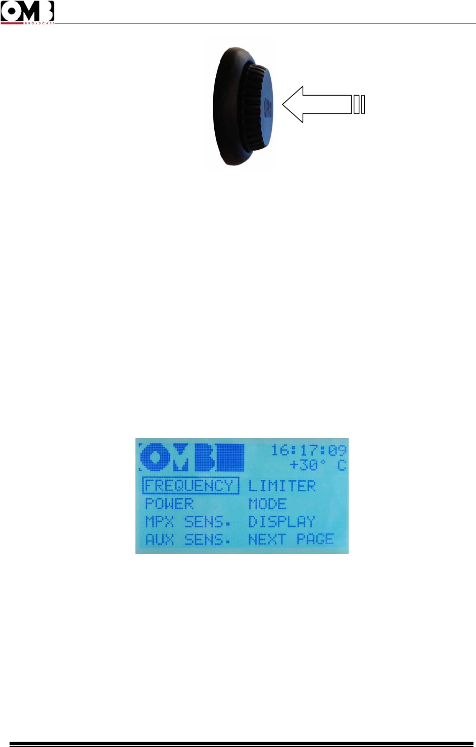
• When pressed briefly like a button, it allows the user to access the menu currently highlighted (or
option currently highlighted).
FM Transmitter
EM 500 DIG PLUS
Technical Manual - v1.0 - April 2012
31
You can also turn the knob clockwise and anti-clockwise to select the various screens showing data that
can be viewed within a menu. For example, alarm events in the view alarms menu.
2.3.2 ESCAPE button
The ESCAPE button allows you to return to the previous menu level. As such, repeatedly pressing this
button returns you to the main screen (you usually only need to press it twice), which appears when you
turn the device on.
2.3.3 Navigating the commands menu
Generally, you can navigate the commands menu as follows:
1) From the main screen (which appears when you turn the device on), turn the knob until one of the
two main menus, VIEW or SETUP, are highlighted.
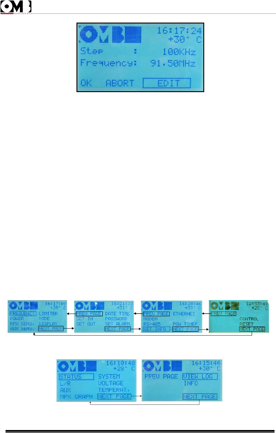
2) Briefly press the knob to access the highlighted menu. The first page of the selected menu will
appear (in the example below, the first page of the SETUP menu).
3) Turn the knob to select the desired sub-menu, then confirm by briefly pressing the knob. In the
example below, the screen for the FREQUENCY sub-menu is shown.
FM Transmitter
EM 500 DIG PLUS
Technical Manual - v1.0 - April 2012
32
4) At this point, depending on the main menu that you have accessed, various options may be
available. Each option is explained in detail in the following chapter, and a brief overview is provided
below:
VIEW menu – used to check the device’s operating parameters and alarms/events; as such, options
are not usually available in its sub-menus. Once you have accessed a sub-menu, turning the knob has
no effect, with the exception of the MPX GRAPH and VIEW LOG sub-menus.
SETUP menu – this was expressly designed to set the transmitter’s parameters; as such, the options
EDIT, ABORT, and OK are available in all the sub-menus.
5) Where required, use the knob according to the instructions provided in each of the following
descriptions of the individual sub-menus.
6) To go back to the previous level (and exit the current menu/sub-menu), press the ESCAPE button.
7) Where necessary, repeat the previous step multiple times until you return to the main screen,
indicated in step 1.
Access to the VIEW and/or SETUP menus may be password protected. If so, you may need to enter a
previously assigned password at step 2.
2.3.4 Additional commands in the SETUP and VIEW menus
- NEXT PAGE and PREV PAGE
The SETUP and VIEW menus are composed of multiple pages; as such, you can access the next page
by selecting the NEXT PAGE sub-menu, and the previous page by selecting PREV. PAGE.
SETUP MENU
VIEW MENU
FM Transmitter
EM 500 DIG PLUS
Technical Manual - v1.0 - April 2012
33
- EDIT, ABORT, and ESCAPE
Once you’ve entered one of the sub-menus in the SETUP menu, turning the knob allows you to select
three commands that appear at the bottom of the screen:
• EDIT - used to access a setting and modify parameters.
• ABORT – used in the same manner as pressing the ESCAPE button, and thus to exit the screen and
return to the previous navigation level without saving any settings made in that sub-menu.
• OK – confirms settings made in a sub-menu.
2.4 Description of the menu.
2.4.1 Default screen
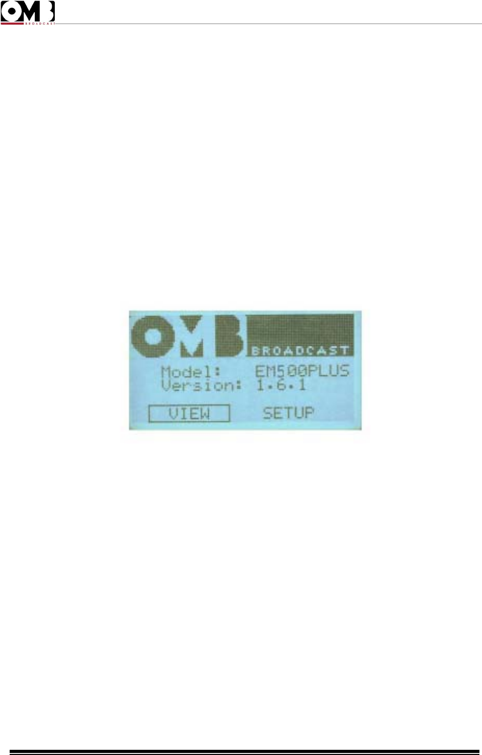
As soon as the device is turned on, the default screen will appear on the display, indicating the following
information:
• Model: indicates the transmitter model.
• Version: indicates the software version installed.
The following main menus can be selected from the bottom part of the screen:
• VIEW: used to view the transmitter’s operating parameters.
• SETUP: used to set operating parameters and many of the device’s functions/services.
The main VIEW menu is normally the menu accessed; as such, pressing the knob will take you to that
menu. For further details, refer to the next section.
Access to the VIEW and SETUP menus may be password protected. If so, you will be asked for the
previously assigned password. The menu and sub-menu screens described below all indicate the
current time and temperature in the top right corner.
In order to avoid misinterpreting the screens, it is important to verify the exact model number of
your device on the main menu, and to safely store this model number.
FM Transmitter
EM 500 DIG PLUS
Technical Manual - v1.0 - April 2012
34
2.4.2 VIEW menu
This menu is used to view the transmitter’s operating parameters; for example, direct power, reflected
power, modulation, etc. It is in turn organized into nine sub-menus divided into the following two pages:
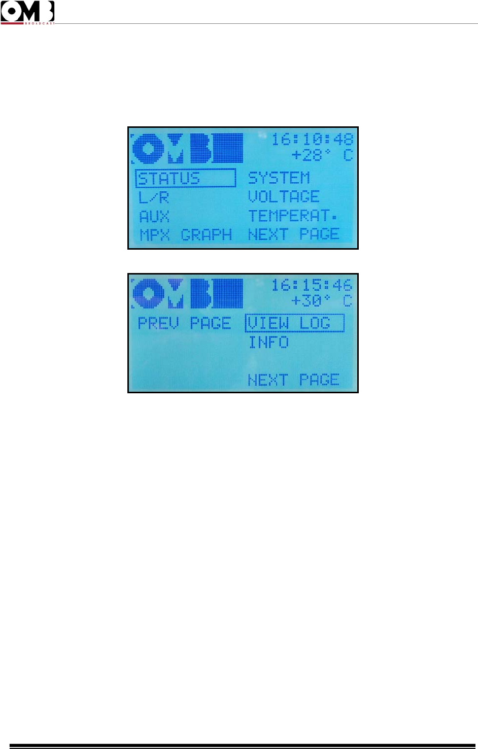
VIEW Page 1
VIEW Page 2
• STATUS – indicates the primary measurements, such as direct power, reflected power, etc.
• L/R – for measuring modulation.
• AUX – for measuring modulation of the auxiliary RDS/SCA signal.
• MPX GRAPH – graphically displays modulation in various modes.
• SYSTEM – indicates the main system parameters, such as frequency, mono/stereo mode, pre-
emphasis, etc.
• VOLTAGE – measures internal power voltages.
• TEMPERAT. – measures internal temperatures.
• VIEW LOG – indicates alarms/events that have occurred during operation.
During normal use of the device, we recommend that the STATUS menu be selected.
Each of the above sub-menus is used to view parameters; as such, options cannot be selected using
the knob, with the exception of the MPX GRAPH and VIEW LOG sub-menus.
• INFO – indicates if the stereo, modem and Ethernet options are present in the equipment or not.
FM Transmitter
EM 500 DIG PLUS
Technical Manual - v1.0 - April 2012
35
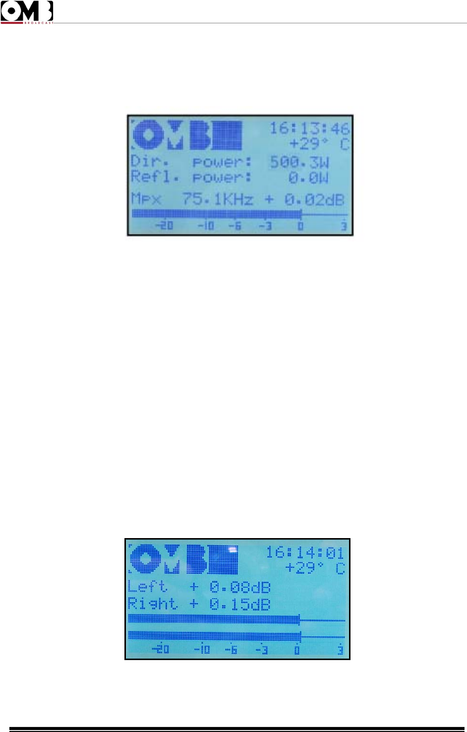
- STATUS sub-menu
The screen for this sub-menu contains the following items:
• Dir. Power: indicates the direct power currently delivered (in the example, 100.3 W).
• Refl. Power: indicates the reflected power currently measured (in the example, 0.0 W).
• Mpx (multiplex) – indicates the peak deviation, expressed in KHz (in the example, 75.1 KHz) and
0.02dB, in reference to a deviation of 75 KHz (0dB = 75 KHz). To change the deviation in function of the
modulating signal, the modulation sensitivity must be set via the MPX SENS submenu, from the main
SETUP menu.
In addition, the bar indicator graphically shows the last parameter indicated.
This screen shows the most important parameters; as such, it is normally the one displayed during
normal use of the transmitter.
In order to avoid saving accidental settings, when the SETUP has been accessed but no operation
performed within a certain period of time, the device will automatically exit the SETUP menu and enter
the VIEW menu, selecting the sub-menu STATUS.
To adjust the output power, go to the sub-menu POWER under the SETUP menu.
- L/R sub-menu
The screen for this sub-menu is used to monitor total peak modulation. It shows the following items:
• Left (left channel) – the current level of the left modulating signal, expressed in dB, against the
nominal level (in the example, +0.08 dB).
FM Transmitter
EM 500 DIG PLUS
Technical Manual - v1.0 - April 2012
36
• Right (right channel) – the current level of the right modulating signal, expressed in dB, against the
nominal level (in the example, +0.15 dB).
In addition, the bar indicators graphically show the two parameters indicated above (peak value).
Depending on the setting made in the SETUP menu, the modulation level can also be viewed via this
screen, which indicates a solo or a multiplex channel (which share the same channel).
Adjustments can be made to the nominal modulation level via the SETUP menu.
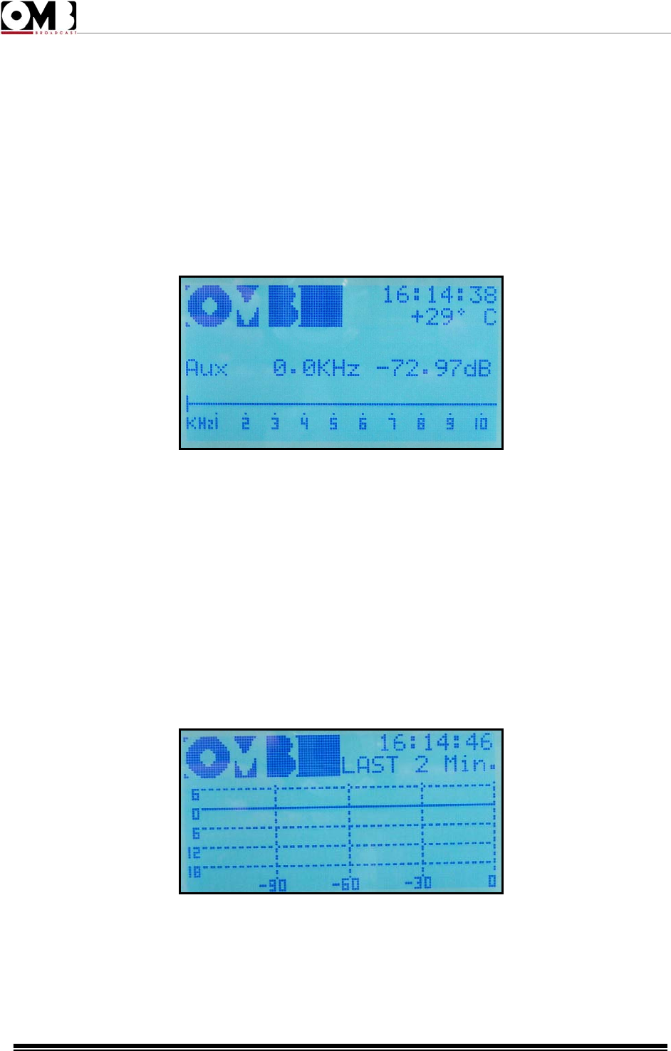
- AUX sub-menu
The screen for this sub-menu shows the modulation level for the Aux RDS/SCA signal:
The above example shows the standard level of the RDS signal (0 KHz), as well as the bar indicator,
which shows the level graphically.
Adjustments can be made to modulation of the auxiliary signal via the SETUP menu.
- MPX GRAPH sub-menu
This sub-menu graphically shows the modulation trend over time in three different scales indicated on
the right. The different scales can be selected by simply turning the knob.
The first (LAST 2 Min.) shows the modulation trend for the last two minutes. The second (LAST 2 Hr.)
shows the modulation trend for the last two hours. The third (LAST 24 Hr.) shows the modulation trend
for the last 24 hours.
The screens are shown cyclically. As such, at the third screen, turning the knob clockwise will take you
back to the first screen.
Similarly, if you are at the first screen and you turn the knob anti-clockwise, the last screen will be
selected.
FM Transmitter
EM 500 DIG PLUS
Technical Manual - v1.0 - April 2012
37
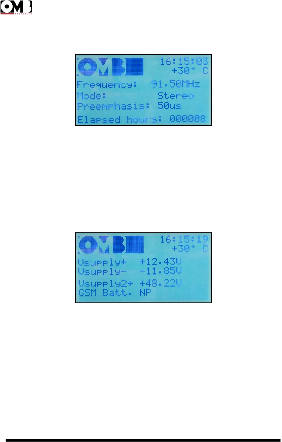
- SYSTEM sub-menu
The screen for this sub-menu shows the key parameters (set frequency, mono/stereo mode, etc.) as
follows:
• Frequency: indicates the operating frequency (in the example, 91.50 MHz).
• Mode: indicates Mono, Stereo, Mono L+R, or Mpx mode (in the example, Stereo).
• Preemphasis: indicates the modulation preemphasis value (in the example, 50 microseconds).
• Elapsed hours: indicates the time elapsed since the device was first turned on in the factory (in the
example, 8 hour).
These adjustments are available via the SETUP menu.
- VOLTAGE sub-menu
The screen for this sub-menu indicates the device’s power voltages as follows:
• Vsupply+ (positive voltage supply) – indicates the positive voltage supply for the low power section (in
the example, +12.43V)
• Vsupply- (negative voltage supply) – indicates the negative voltage supply for the low power section
(in the example, -11.85V)
• Vsupply2+ (positive voltage 2) – indicates the voltage supply for the power section (in the example,
+48.22V)
• GSM Batt (GSM battery voltage supply) – indicates the voltage for the battery that powers the optional
remote control unit via GSM cellular phone (in the example, NP indicates that the optional module is not
present)
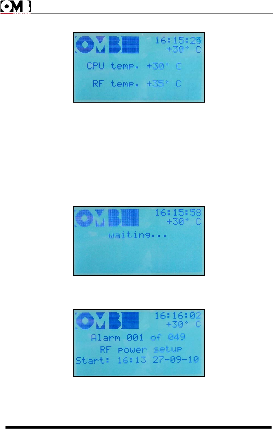
- TEMPERAT. sub-menu
The screen for this sub-menu indicates the current operating temperatures as follows:
FM Transmitter
EM 500 DIG PLUS
Technical Manual - v1.0 - April 2012
38
• CPU temp. – indicates the current CPU temperature (in the example, +30 °C)
• RF temp. – indicates the RF temperature, if pertinent to the model in use (in the example, +35 °C )
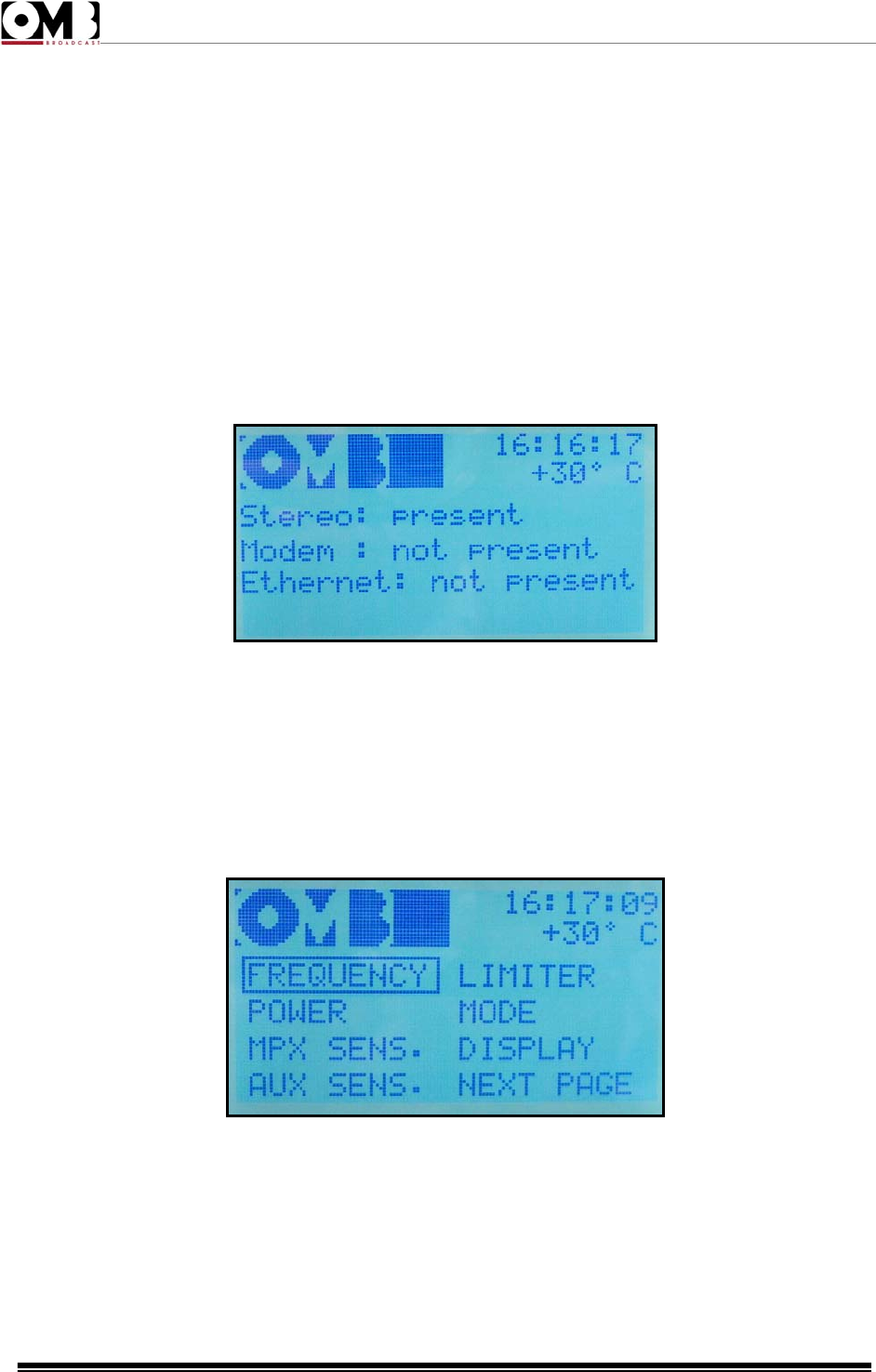
- VIEW LOG sub-menu
This sub-menu provides a historical record of events (transmitter turned on, turned off, on stand-by,
etc.) and alarms (insufficient modulation, excessive reflected power, etc.) that took place during
operation. The transmitter’s memory (non volatile) can record up to 100 alarms/events. As soon as you
enter this menu, the transmitter takes a few seconds to update the data; during this time, the screen
waiting... appears.
Next, the following screen will appear:
If the device already has 100 events/alarms in its memory, a new event/alarm that occurs will cancel out
the oldest recording so that the new event/alarm can be saved (FIFO).
FM Transmitter
EM 500 DIG PLUS
Technical Manual - v1.0 - April 2012
39
Via the SETUP menu, you can decide whether to activate/deactivate each alarm (e.g., low power,
insufficient modulation, etc.), and set new detection thresholds. Through this menu, you can also delete
the alarm history.
If an alarm event occurs when you are accessing the VIEW LOG menu, you must exit and re-enter the
VIEW LOG menu in order to view the alarm on the event list.
To select subsequent alarm events (less recent, with higher numbers), turn the knob anti-clockwise;
turning the knob clockwise will take you to the most recent events.
- IN FO sub-menu
This sub-menu provides information about the presence of the different options the equipment may
have or not present.
In the example only the Stero option is present, and the Modem and Ethernet options are not.
2.4.3 SETUP menu
This menu allows you to program the device’s operating parameters; for example, operating frequency,
output power, modulation, passwords, etc. It is divided into the following four pages:
SETUP Page 1
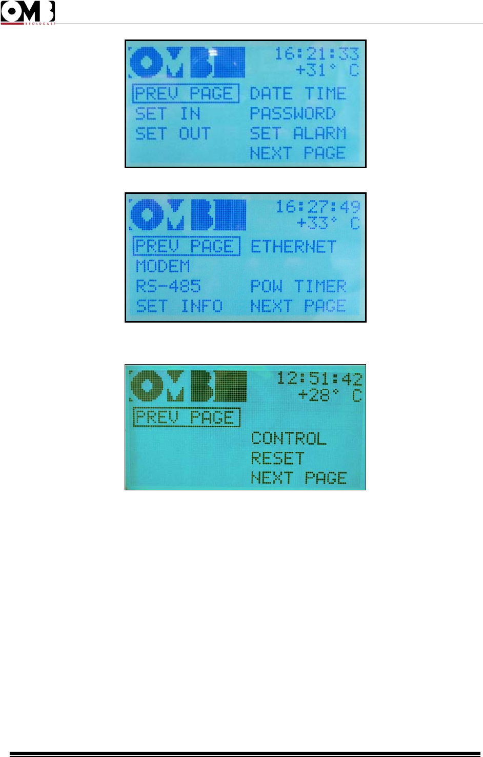
FM Transmitter
EM 500 DIG PLUS
Technical Manual - v1.0 - April 2012
40
SETUP Page 2
SETUP Page 3
SETUP Page 4
To move from one page to another, select the commands NEXT PAGE or PREV PAGE using the knob,
then press to confirm.
As you can see, the four pages allow you to access the following settings:
• FREQUENCY – frequency increment steps and operating frequency
• POWER – output power level
• MPX SENS – modulation sensitivity
• AUX SENS – auxiliary modulation sensitivity, e.g., RDS
• LIMITER – maximum deviation limiter
• MODE – transmission mode, e.g., stereo/mono and pre-emphasis
• DISPLAY – display backlighting and contrast
• SET IN – logic levels for the ENABLE line and related activation mode
• SET OUT – logic levels for remote control
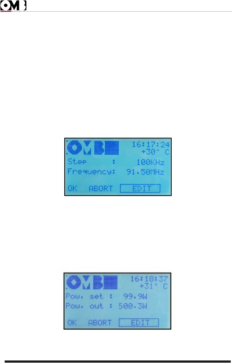
FM Transmitter
EM 500 DIG PLUS
Technical Manual - v1.0 - April 2012
41
• DATE TIME – system date and time
• PASSWORD – set passwords
• SET ALARM – alarm identification mode
• ETHERNET – Ethernet LAN interface settings
• RS-485 – RS485 interface settings
• POW TIMER – set automatic power reduction during specific time periods
• MODEM – modem modes
• CONTROL – control modes
• RESET – modem reset
- FREQUENCY setting
Used to define the transmitter’s operating frequency.
The following parameters can be set:
• Step – frequency increments can be selected (in the example, 100 KHz)
• Frequency – operating frequency
- POWER setting
Used to adjust the transmitter’s output power.
The display shows the following:
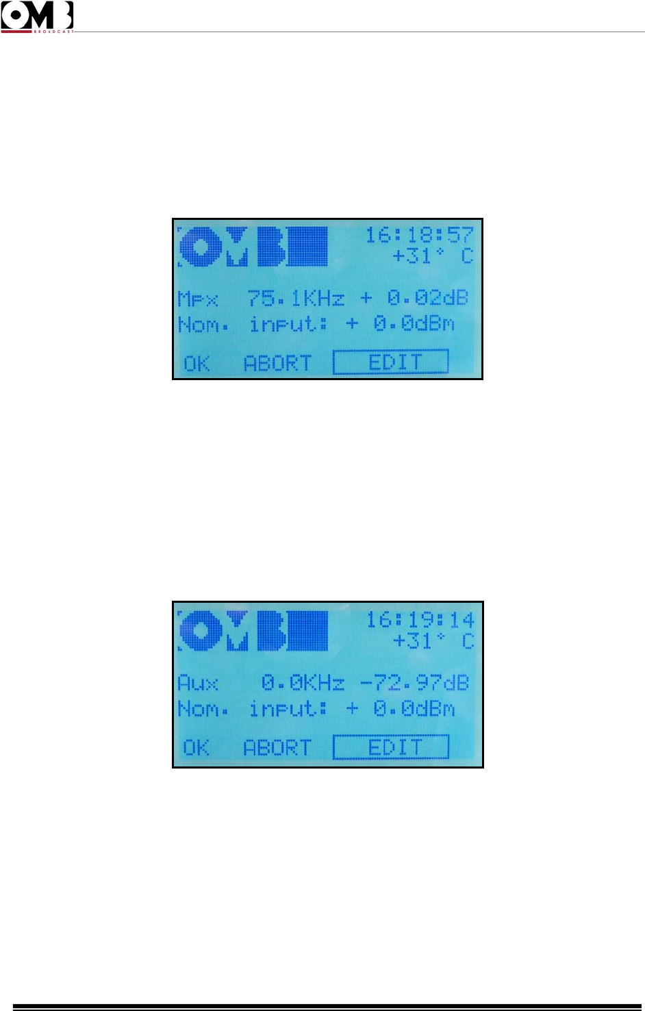
FM Transmitter
EM 500 DIG PLUS
Technical Manual - v1.0 - April 2012
42
• Pow. set – set power
• Pow. out – measurement of the power supplied
- MPX SENS setting
Used to adjust modulation input sensitivity according to the low frequency level available.
The display shows the following:
• Mpx – followed by the deviation value, expressed in KHz (in the example, 75.1 KHz) and in dB, in
reference to a deviation of 75 KHz (0dB = 75 KHz)
• Nom. input – nominal value of low frequency input level (in the example, + 0.0 dBm)
- AUX SENS (RDS/SCA sensitivity modulation) setting
Used to adjust the present modulation result of the single auxiliary signal (RDS/SCA).
The display shows the following:
• Aux – followed by a deviation value expressed in KHz (in the example, 0.0 KHz) and in dB, in
reference to a deviation of 75 KHz (0dB = 75 KHz)
• Nom. input – nominal value of auxiliary signal input level
To change the auxiliary modulation:
1) Ensure that the EDIT option is selected; otherwise, turn the knob to select it, then press to confirm.
2) A value will be indicated after Nom. input. This indicator is normally predefined at +0.0 dBm.
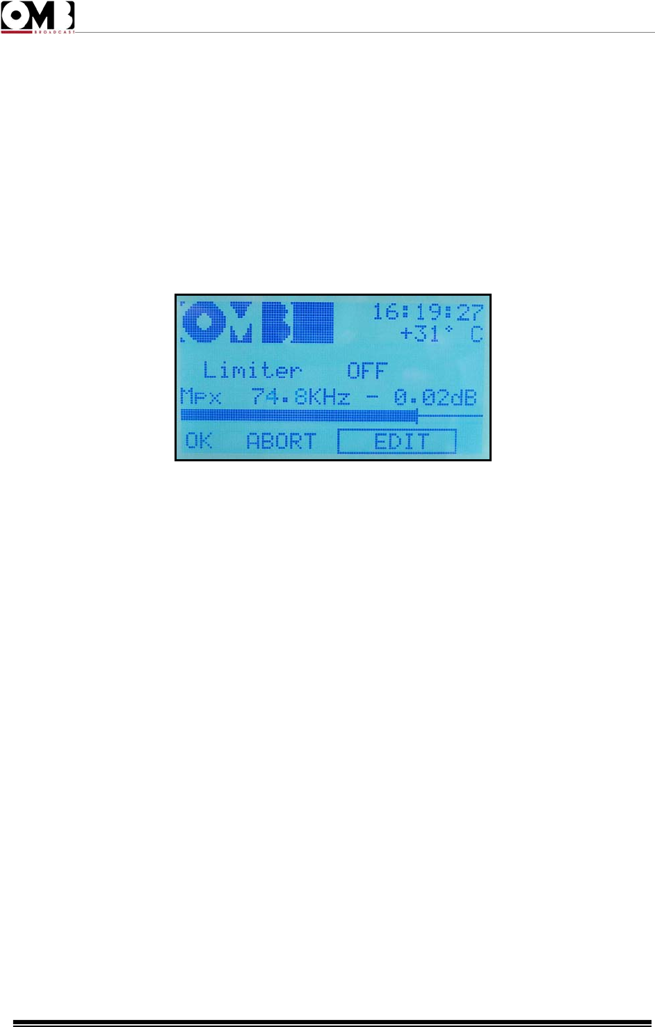
FM Transmitter
EM 500 DIG PLUS
Technical Manual - v1.0 - April 2012
43
3) Turn the knob to change the value, based on the modulation level used. The peak deviation indicated
by Aux, expressed in KHz, will consequently change. You will note that, to the right of the deviation, the
value of the modulating signal will be indicated in dB, against the nominal value set.
4) Ensure that the deviation measured does not exceed local regulations, then press the knob to
confirm the setting.
5) Using the knob, select OK to save the settings, EDIT to make further changes, or ABORT to exit
without saving the new settings, then press to confirm
- LIMITER setting
Used to limit the peak modulation at a maximum value.
The display shows the following:
• Limiter – followed by OFF if deactivated, or by a value expressed in dB, in reference to a deviation of
75 KHz (0dB = 75 KHz)
• Mpx – measurement of the current peak deviation value, expressed in KHz (in the example, 74.8 KHz)
in dB, in reference to a deviation of 75 KHz (0dB = 75 KHz)
In addition, the bar indicator graphically shows the current peak deviation value.
By changing the Limiter, you can set a maximum modulation value beyond which the limiter will
activate.
When the limiter begins to intervene, the modulation distortion increases. As such, the modulation
sensitivity should be adjusted so the limiter intervenes sporadically. Using this approach, its operation is
generally imperceptible.
- MODE setting
Used to define whether the transmitter operates in mono or stereo, and its pre-emphasis value.
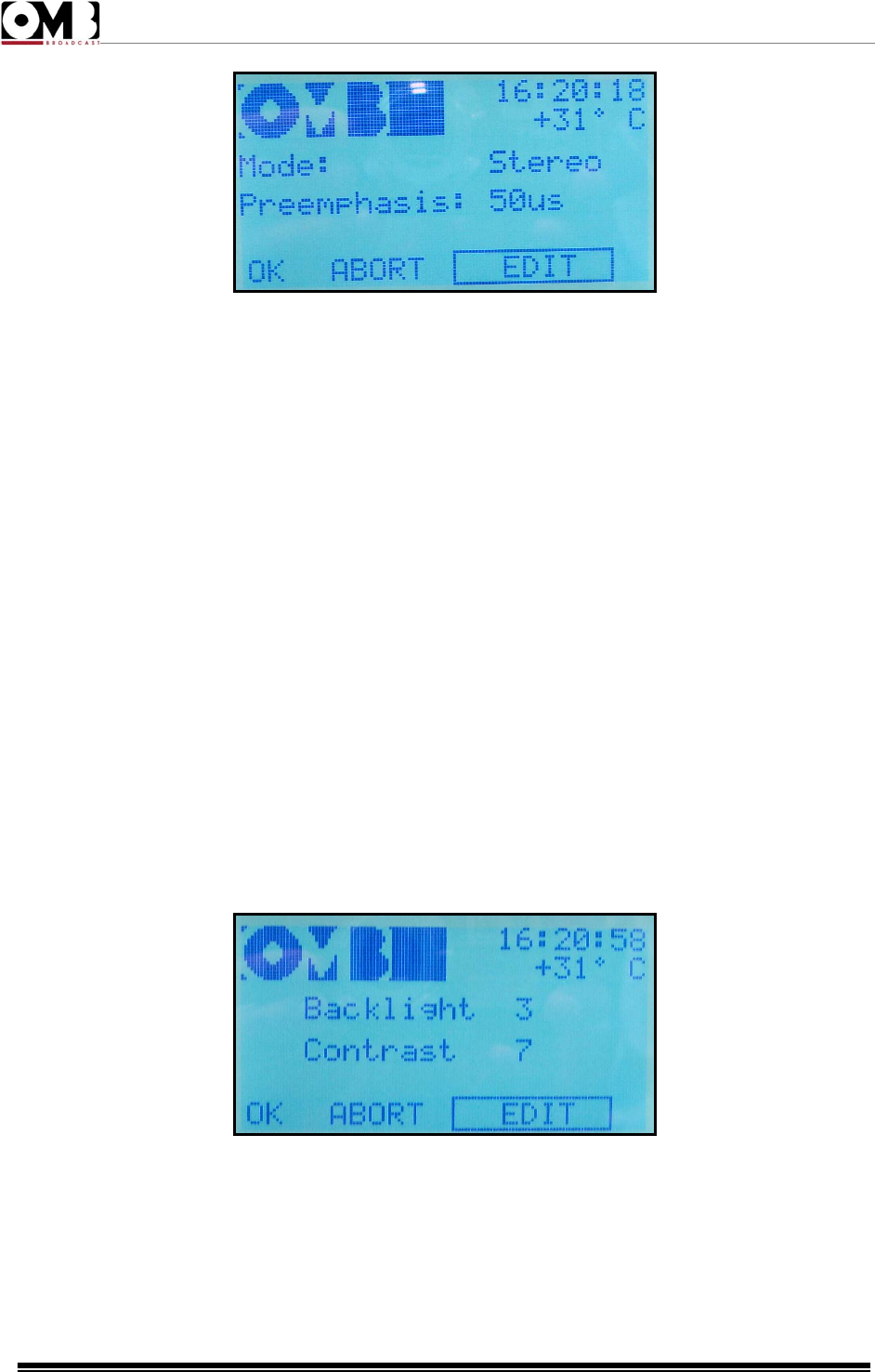
FM Transmitter
EM 500 DIG PLUS
Technical Manual - v1.0 - April 2012
44
The display shows the following:
• Mode – followed by Mono (from the RIGHT input, Stereo, Mono L+R (monophony obtained through
the sum of the stereo channels), or Mpx (external multiplex modulation signal originating from the MPX
input.
• Pre-emphasis – followed by the current pre-emphasis value, expressed in microseconds.
To change the auxiliary modulation:
1) Ensure that the EDIT option is selected; otherwise, turn the knob to select it, then press to confirm. A
value will be indicated after Mode.
2) Turn the knob to change the setting to Mono, Stereo, Mono L+R, or Mpx according to your
requirements, then press the knob. A value will be indicated after Preemphasis.
3) Turn the knob to change the setting to 0, 25, 50, or 75 microseconds, according to your requirements
(50 microseconds for Spain), then press the knob to set the value.
4) Using the knob, select OK to save the settings, EDIT to make further changes, or ABORT to exit
without saving the new settings, then press to confirm.
- DISPLAY setting
Used to optimize display legibility, based on ambient lighting conditions and the angle of the visual field.
This screen shows:
• Backlight – followed by the current backlighting value
• Contrast – followed by the current contrast value
To change these parameters:
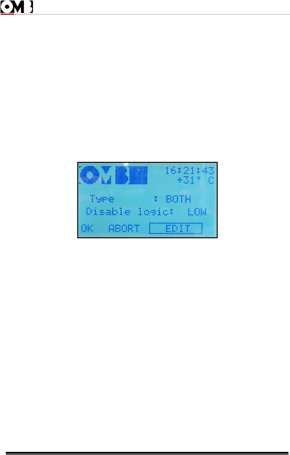
FM Transmitter
EM 500 DIG PLUS
Technical Manual - v1.0 - April 2012
45
1) Ensure that the EDIT option is selected; otherwise, turn the knob to select it, then press to confirm. A
value will be indicated after Backlight.
2) Turn the knob to change the backlighting, which will immediately change based on the setting
selected (three levels are available; 3 corresponds to maximum illumination), then press to confirm. A
value will be indicated after Contrast.
3) Turn the knob to change the contrast, which will immediately change based on the setting selected
(twenty levels are available; 1 corresponds to maximum contrast), then press the knob to set the value.
4) Using the knob, select OK to save the settings, EDIT to make further changes, or ABORT to exit
without saving the new settings, then press to confirm.
- SET IN (remote control input) setting
Used to set logic levels for the ENABLE line in the remote control input:
The following parameters can be adjusted:
• Type – transmitter’s activation/deactivation mode. You can define whether this takes place via the
front ON/STAND-BY button only (the ENABLE line is therefore deactivated), the rear line only (the front
ON/STAND-BY button is deactivated), or using both commands (either the front button or the ENABLE
line). To this end, the settings BOTH, LOCAL, and REMOTE (only via the ENABLE line) are available.
• Disable logic: - defines whether activation of the command takes place using a LOW or HIGH logic
level. The device is normally deactivated with a low level, meaning when this line is grounded.
To set these parameters:
1) Ensure that the EDIT option is selected; otherwise, turn the knob to select it, then press to confirm. A
value will be indicated after Type.
2) Turn the knob to change the setting to BOTH, LOCAL, or REMOTE according to your requirements,
then pres the knob to set the value. A value will be indicated after Disable logic.
3) Turn the knob to change the setting to LOW or HIGH according to your requirements, then press the
knob to set the value.
4) Using the knob, select OK to save the settings, EDIT to make further changes, or ABORT to exit
without saving the new settings, then press to confirm
The ENABLE line is equipped with an internal pull-up resistance that maintains the line on high status in
the absence of a signal or connection.
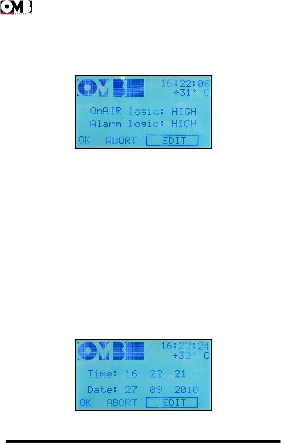
FM Transmitter
EM 500 DIG PLUS
Technical Manual - v1.0 - April 2012
46
If BOTH is set under Type and the ENABLE line on the rear input is short-circuited, the ON/STAND-BY
button won’t work correct when this setting performs a logic function (OR) for the two commands.
- SET OUT (remote control output) setting
This screen allows you to define the logic levels (high/low) used for remote control:
You can define whether the status of the following lines normally has a HIGH or LOW logic level:
• OnAIR logic – ON THE AIR line, which signals when the device is powered up
• Alarm logic – ALARM line, which signals the presence of an alarm
To set these parameters:
1) Ensure that the EDIT option is selected; otherwise, turn the knob to select it, then press to confirm. A
value will be indicated after OnAIR logic.
2) Turn the knob to change the setting to LOW or HIGH according to your requirements, then press the
knob to set the value. A value will be indicated after Alarm logic.
3) Turn the knob to change the setting to LOW or HIGH according to your requirements, then press the
knob to set the value.
4) Using the knob, select OK to save the settings, EDIT to make further changes, or ABORT to exit
without saving the new settings, then press to confirm
The alarm activation threshold levels can also be defined via the alarm menu
- DATE TIME setting
Used to set the date and time used by the system to generate an alarm history, and for other functions.
The display shows the following:
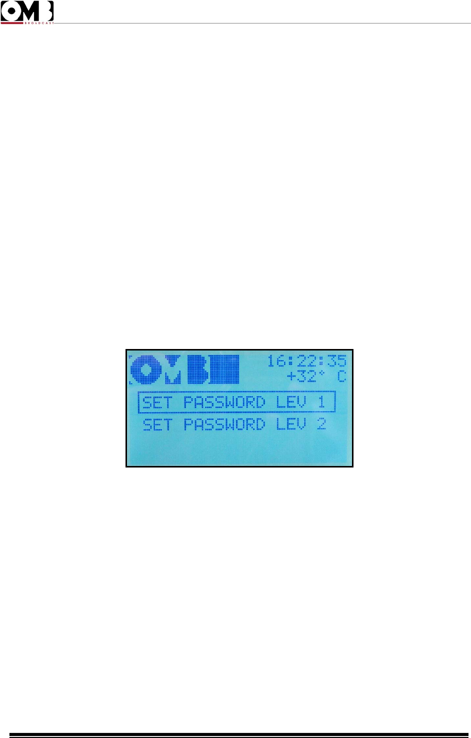
FM Transmitter
EM 500 DIG PLUS
Technical Manual - v1.0 - April 2012
47
• Time – followed by the currently set time
• Date – followed by the currently set date
It is important to correctly set the time and date; otherwise, the alarm history and various other
functions will not operate correctly.
- PASSWORD (menu protection) setting
Used to activate and set the passwords to protect access to the menus. Two passwords are available:
• LEV 1 – this level is more restrictive, and protects access to both the VIEW and the SETUP main
menus.
• LEV 2 – protects access to the SETUP menu only.
Each password is composed of four alphanumeric characters (numbers 0-9 or letters A-Z).
Activate only one of the two passwords (LEV 1 or LEV 2) according to your requirements. Activating
both passwords may cause problems when using the transmitter.
If one of the two passwords is activated, remember to store it in a safe location. Losing a
password requires that the level 3 password be used; this password should never normally be
used.
The display shows the following:
• SET PASSWORD LEV 1
• SET PASSWORD LEV 2
• In order to gain confidence with the password settings menu and with its operation, we recommend
that the password be set as 0 0 0 0 (four zeros) the first time.
LEVEL 1 PASSWORD
To protect both main menus, activate/set the LEV 1 password as follows:
1) Select SET PASSWORD LEV 1 with the knob, then press to confirm.
2) Using the knob, select EDIT and press to confirm. OFF (password deactivated) will be selected. Turn
the knob to select ON, then press to confirm. The first character in the password will be highlighted.
3) Turn the knob to select the first character, then press to confirm. The second character in the
password will be highlighted.
4) Turn the knob to select the second character, then press to confirm. The third character in the
password will be highlighted.

FM Transmitter
EM 500 DIG PLUS
Technical Manual - v1.0 - April 2012
48
5) Turn the knob to select the third character, then press to confirm. The fourth character in the
password will be highlighted.
6) Turn the knob to select the fourth character, then press to confirm. The first character in the Confirm
line will be highlighted; repeat the same password on this line in order avoid errors in setting the
password.
7) Set the four characters on the Confirm line as explained in steps 3) to 6).
8) Using the knob, select OK to save the settings, EDIT to make further changes, or ABORT to exit
without saving the new settings, then press the knob to confirm.
9) Store the password in a safe place.
If the four characters in the CONFIRM line do not correspond to the ones entered in the first line, a
Wrong password message will appear. Press the knob to delete the screen and return to step 2).
Once a level 1 password is activated, each time someone attempts to access the SETUP menu, they
will receive an Insert PASSWORD message asking for the password to be entered. Access to the
VIEW menu is timed, and the password will only be requested if the VIEW menu is not used for a given
period of time.
LEVEL 2 PASSWORD
If you wish to protect the SETUP menu only, activate/set the LEV 2 password using the same
procedure as outlined above, ensuring that SET PASSWORD LEV 2 is selected at step 1).
Once a level 2 password is activated, each time someone attempts to access the SETUP menu, they
will receive an Insert PASSWORD message asking for the level 2 password to be entered. The VIEW
menu will remain accessible at all times.
- SET ALARM setting
As previously explained, if a parameter falls outside a given value for a specific period of time (for
example: modulation 6 dB lower than the nominal value for more than 10 minutes), the ON LED will
light up in red and the bottom part of the display will indicate the associated alarm (e.g., Mpx Low =
insufficient modulation). The last 100 alarm events can be accessed via the VIEW LOG alarm history
menu, under the main VIEW menu.
This menu allows you to activate/deactivate each diagnostic alarm, and to set its sensitivity level and
the time period beyond which the alarm is activated. In addition, the RESET LOG function is available,
which allows you to delete the alarm history saved.
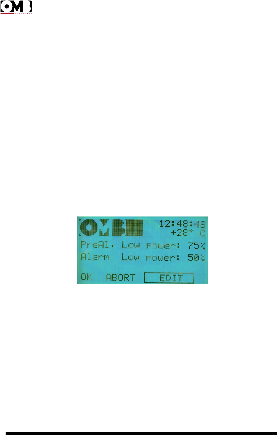
FM Transmitter
EM 500 DIG PLUS
Technical Manual - v1.0 - April 2012
49
The following alarms can be set:
• LOW RF POW – an alarm is issued when the RF power is detected at below a certain percentage
value.
• HIGH VSWR – an alarm is issued when an excessive SWR (standing wave ratio) is detected.
• UNLOCK – an alarm is issued when the internal PLL frequency synthesizer is unlocked.
• MPX – an alarm is issued when low (or no) modulation is detected for a given period of time.
In general, to set alarms:
1) Turn the knob to select the alarm that you wish to activate/configure (e.g., LOW RF POW), then
press to confirm.
2) Ensure that the EDIT option is selected; otherwise, turn the knob to select it, then press to confirm.
The first value to be set will be highlighted.
3) Turn the knob to change the setting according to your requirements, then press to set.
4) If the setting includes this option, the second alarm setting will be highlighted. Turn the knob to
change the setting according to your requirements, then press to set.
5) Using the knob, select OK to save the settings, EDIT to make further changes, or ABORT to exit
without saving the new settings, then press the knob to confirm.
LOW RF POW
Two parameters can be set from this screen:
• PreAl. Low Power – if the output power falls below the percentage set here, a warning pre-alarm is
issued by flashing the ALARM LED. The pre-alarm is not saved in the event history.
• Alarm Low Power – if the output power falls below the percentage set here, an alarm is issued via a
steadily lit ALARM LED. Obviously, this alarm is saved in the event history.
To set the low power pre-alarm and alarm:
1) Ensure that the EDIT option is selected; otherwise, turn the knob to select it, then press to confirm. A
value will be indicated after PreAl.Low Power.
2) Turn the knob to change the percentage to meet your requirements, then press to confirm. A value
will be indicated after Alarm Low Power.
3) Turn the knob to change the percentage to meet your requirements, then press to confirm.
4) Using the knob, select OK to save the settings, EDIT to make further changes, or ABORT to exit
without saving the new settings, then press to confirm.
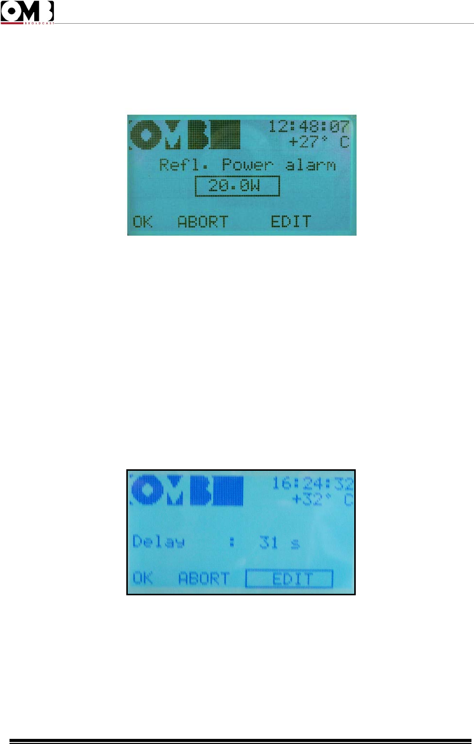
FM Transmitter
EM 500 DIG PLUS
Technical Manual - v1.0 - April 2012
50
HIGH VSWR
From this screen, a value can be set for reflected power, beyond which a high SWR alarm will be
issued.
In the above example, the Refl. Power alarm is issued when a reflected power of 20.0 W is exceeded.
To set the high reflected power alarm:
1) Ensure that the EDIT option is selected; otherwise, turn the knob to select it, then press to confirm. A
value will be indicated after Refl. Power alarm.
2) Turn the knob to change the reflected power level according to your requirements, then press to
confirm.
3) Using the knob, select OK to save the settings, EDIT to make further changes, or ABORT to exit
without saving the new settings, then press to confirm.
UNLOCK
From this screen, a time can be set, beyond which an alarm will be issued if the transmitter’s internal
synthesizer continues to be unlocked.
In the above example, if the synthesizer is unlocked for a Delay of 31 seconds, an alarm will be issued.
To set the synthesizer unlock alarm:
1) Ensure that the EDIT option is selected; otherwise, turn the knob to select it, then press to confirm. A
value will be indicated after Delay.
2) Turn the knob to change the time according to your requirements, then press to confirm.
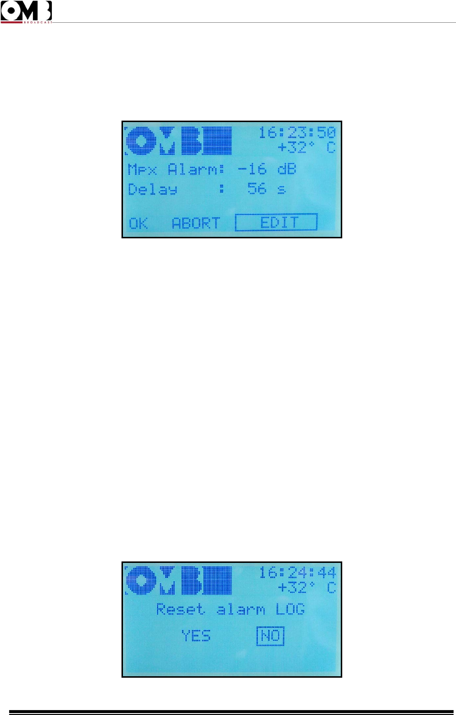
FM Transmitter
EM 500 DIG PLUS
Technical Manual - v1.0 - April 2012
51
3) Using the knob, select OK to save the settings, EDIT to make further changes, or ABORT to exit
without saving the new settings, then press to confirm
MPX
From this screen, you can personalize the insufficient modulation alarm. Two parameters can be set:
• Mpx Alarm – the threshold below which modulation, expressed in dB in reference to a deviation of 75
KHz (0dB = 75 KHz), is considered insufficient.
• Delay – the time in seconds after which, if modulation remains insufficient, an alarm is issued.
In the above example, the alarm is issued only when modulation constantly remains at least 16 dB
below 75 KHz for 56 seconds.
To set the insufficient modulation pre-alarm and alarm:
1) Ensure that the EDIT option is selected; otherwise, turn the knob to select it, then press to confirm. A
value will be indicated after Mpx Alarm.
2) Turn the knob to change the modulation to a level that is considered insufficient for your
requirements, then press to confirm.
A value will be indicated after Delay.
3) Turn the knob to change the time interval according to your requirements, then press to confirm.
4) Using the knob, select OK to save the settings, EDIT to make further changes, or ABORT to exit
without saving the new settings, then press to confirm.
RESET LOG
As previously mentioned, this menu does not allow you to configure alarms, but rather to delete the
alarm history.
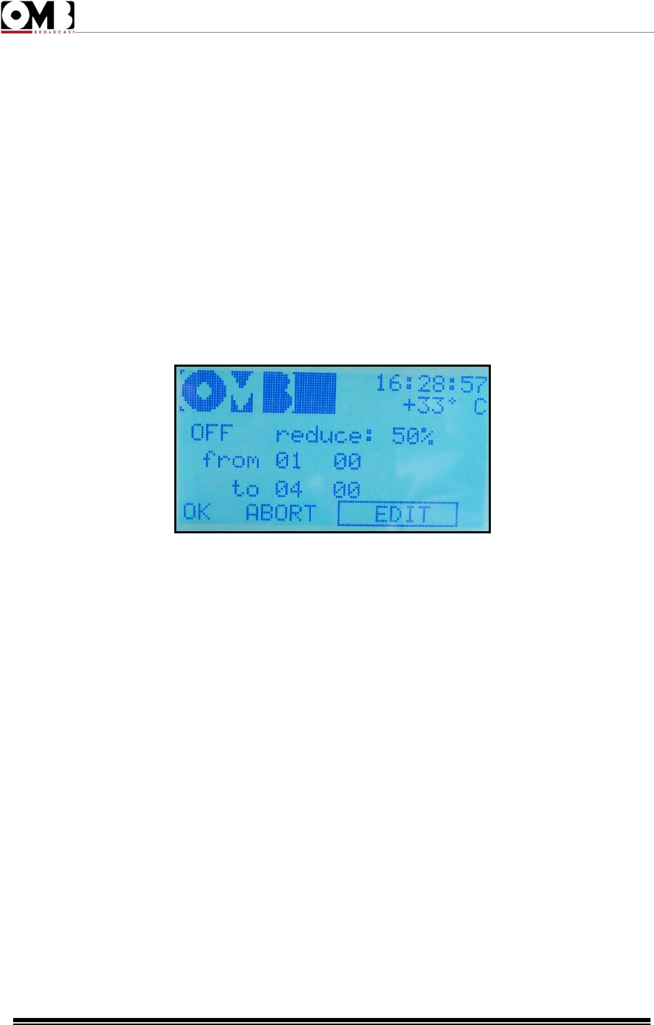
FM Transmitter
EM 500 DIG PLUS
Technical Manual - v1.0 - April 2012
52
When you access this menu, two simple commands are available by turning the knob:
• YES – the alarm history will be deleted. The message waiting… will appear while the history is being
deleted.
• NO – the alarm history will not be deleted (in cases of accidental access to the sub-menu, where there
is no actual need to delete the history).
After either command is selected, the display will return to the SET ALARM sub-menu.
The alarm/event history delete function does not request confirmation; as such, be careful not to
accidentally delete the history.
- POW TIMER setting
Used to automatically decrease the transmitter’s power by a given percentage during a specific time
period (e.g., night time).
The display shows the following parameters:
• OFF or ON – power reduction deactivated (OFF) or activated (ON).
• Reduce: percentage of power reduction compared to the power set via the menu.
• From – followed by two sets of numbers (hour and minute). Indicates the time in which the transmitter
will reduce power.
• To – followed by two sets of numbers (hour and minute). Indicates the time in which the transmitter will
return to the normal power level set via the menu.
To set automatic power reduction:
1) Ensure that the EDIT option is selected; otherwise, turn the knob to select it, then press to confirm. A
value will be displayed after OFF or ON.
2) Turn the knob to set OFF or ON according to your requirements, then press to confirm. A value will
be indicated after reduce.
3) Turn the knob to change the power reduction percentage, then press to confirm. The first number
(hour) will be highlighted after from.
4) Turn the knob to change the hour in which the power reduction will start (24-hour clock), then press
to confirm. The second number (minutes) will be highlighted after from.
5) Turn the knob to change the minute in which the power reduction will start, then press to confirm. The
first number (hour) will be indicated after to.
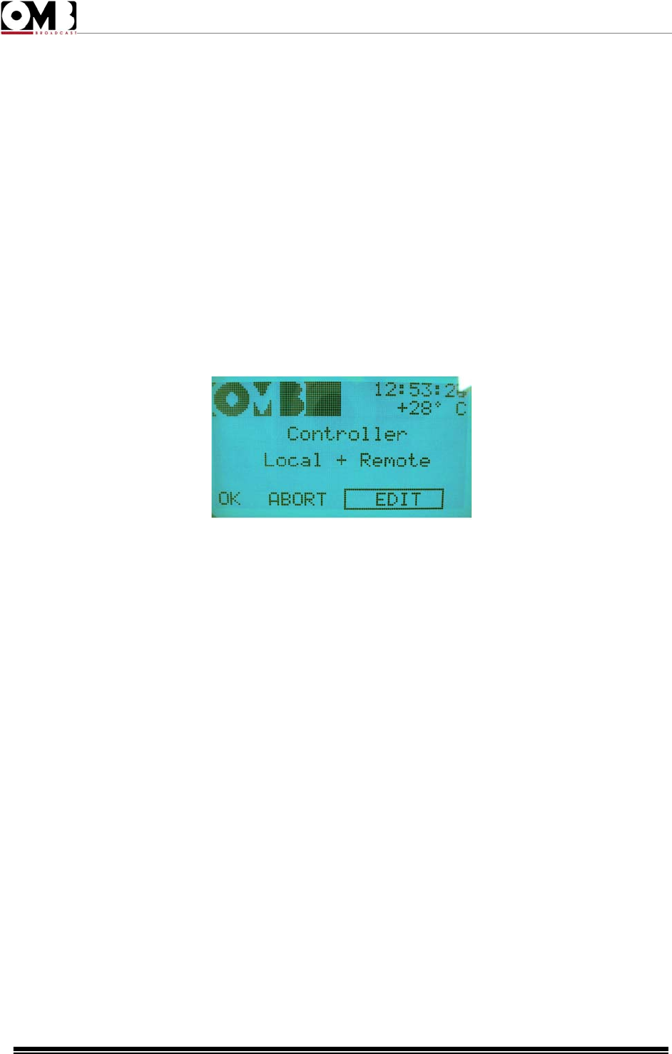
FM Transmitter
EM 500 DIG PLUS
Technical Manual - v1.0 - April 2012
53
6) Repeat steps 4 and 5 to set the time in which the transmitter will return to normal power.
7) Using the knob, select OK to save the settings, EDIT to make further changes, or ABORT to exit
without saving the new settings, then press to confirm.
- MODEM setting
If the transmitter is equipped with an optional modem, its parameters can be defined via this screen. For
further details, refer to the documentation provided with this option.
If a modem has not been installed, the screen will indicate Modem not present.
- CONTROL setting
Used to select how to control the transmitter.
1) Ensure that the EDIT option is selected; otherwise, turn the knob to select it, then press to confirm.
The current option will be hightlighted.
2) Turn the knob to set Local + Remote, Local or Remote according to your requirements, then press to
confirm.
3) Using the knob, select OK to save the settings, EDIT to make further changes, or ABORT to exit
without saving the new settings, then press to confirm.
- Hidden menus (under level 3 password)
Beside the two level 1 and level 2 passwords, a third password, called “level 3 password” is available.
It’s preset during the production, it’s always active and allows to access the SETUP sub menu and the
one which allows the activation/change of the level 1 and level 2 passwords even when the user has
activated and forgotten them.
There are two hidden menus which can be accessed only by entering the level 3 password. Briefly,
accessing the SETUP menu by means of the level 3 password allows to:
• Access the SETUP sub menu and the one which allows the activation/change of the level 1 and level
2 passwords even when the user has activated and forgotten them.
• Change the level 3 password in order to change the one preset during the production of the
equipment.

FM Transmitter
EM 500 DIG PLUS
Technical Manual - v1.0 - April 2012
54
- Accessing the level 3 password
To access the SETUP submenu when you have forgotten the level 1 or level 2 password currently
active:
1) Use the knob to select the SETUP menu and press it to confirm.
2) When the password is prompted, enter the level 3 password which was set during the production to
A B C D.
3) Select the password change menu and change the level 1 or level 2 password which is currently
active
4) Note down the new level 1 or level 2 password currently active and store it in a safety pace.
- Changing the level 3 password
Some unauthorized people who know the level 3 password preset in the production could alter the
setting of the transmitter even when it’s protected with either one or both the level 1 or two passwords.
For this reason you can change the level 3 password preset in the production. This operation must be
done only if you are absolutely sure to note down the new level 3 password and stored it in a safety
place.
IMPORTANT! Always note down the level 3 password and sore it in a safety place. Should you
loose it, the total reprogramming of the equipment or the CPU replacement at OMB will be
mandatory – with the related costs which this operation involves. This kind of service is not
included in the warranty.
To change the level 3 password :
1) Use the knob to select the SETUP menu and press it to confirm.
2) When the password is prompted, enter the level 3 password which was set during the production to
A B C D.
3) Select the PASSWORD submenu. As you can see, the command SET PASSWORD LEV 3 (set level
3 password) also appears in it
4) Select SET PASSWORD LEV 3 and change the password by following the procedure stated
previously.
You can change the level 3 password, but not disable it, because its setting is always fixed to ON.

FM Transmitter
EM 500 DIG PLUS
Technical Manual - v1.0 - April 2012
55
2.5 Troubleshooting.
All instructions set in this manual are followed, the EM 500 DIG PLUS series will guarantee several
years of perfect service. However, should problems arise, refer to this chapter before contacting the
local authorized assistance point.
2.5.1 Error messages
The following table explains the meaning of the main error messages and indicates the actions to be
taken in order to solve the problem.
All alarms will be usually shown in any screen you are, and they will be overlapped on the upper screen
section, where you normally see the company logo, system temperature and system time. In addition,
the ALARM LED will light.
The messages below may appear during the amplifier normal operation as well as when the alarm data
are displayed in the VIEW LOG sub-menu.
- Mpx low (insufficient modulation)
The Mpx low alarm message appears when an insufficient modulation lasts for more than a given time.
Both alarm delay and alarm threshold can be set in the alarms menu, respectively up to 180 seconds
and < -16dB (as to 75 KHz frequency deviation, that is 0dB = 75 KHz).
- Refl Power High (excessive reflected power)
The Refl Power high alarm message appears when the reflected power level exceeds a threshold,
usually set in the range from 5% to 7% of the maximum nominal power level. The threshold level can be
adjusted via the alarms menu.
If necessary, the maximum reflected power level can be automatically limited to the ~ 10% of the
maximum output power level reducing the direct output power.
- Over temperature
The Over temperature alarm may be referred to a system over temperature (CPU Temp.) or only to a
RF power stage over temperature (RF temp.); each of the said temperatures is taken via a specific heat
probe.
Before reaching the max allowed temperature, the alarm LED starts flashing, to signalize the approach
to the limit condition. If the threshold is exceeded, the alarm LED stops flashing and starts steadily
lighting. In this condition the output power level will be progressively reduced, to limit dissipation without
completely blocking the transmitter operation.
To check whether the over temperature is due to whole system or to the RF power stage only, select
the Temperat. sub-menu, in the View menu, which displays both the temperatures:
CPU temp. = system temperature
RF temp. = RF power stage temperature

FM Transmitter
EM 500 DIG PLUS
Technical Manual - v1.0 - April 2012
56
- Unlock (unlocked PLL synthesizer)
Unlock shows an unlock status of the built in synthesizer, generally meaning a real transmitter fault.
When this failure happens it’s quite important to contact the local authorized assistance point.
Depending on the software release of the control firmware, this alarm is often “masked” by the
consequent low RF direct output power alarm, however the LOCK LED keeps off whereas the ALARM
LED steadily lights.
With the most recent software releases the Synthesizer unlock priority alarm will be shown in the
current screen, immediately signaling such condition.

FM Transmitter
EM 500 DIG PLUS
Technical Manual - v1.0 - April 2012
57
CONTENTS:
3.1 Internal modules location . . . . . . . . . . . . . 58
3.1.1 Power supply. . . . . . . . . . . . . . . . . . .59
3.1.2 600W FM Power Module . . . . . . . . . . . .60
3.1.3 Low Pass Filter . . . . . . . . . . . . . . . . .63
3.1.4 Auxiliary power supply . . . . . . . . . . . . . 65
3.1.5 Compada Board . . . . . . . . . . . . . . . . 66
3.2 Schematics. . . . . . . . . . . . . . . . . . . . 67
S
Se
ec
ct
ti
io
on
n
3
3
I
IN
NT
TE
ER
RN
NA
AL
L
M
MO
OD
DU
UL
LE
ES
S
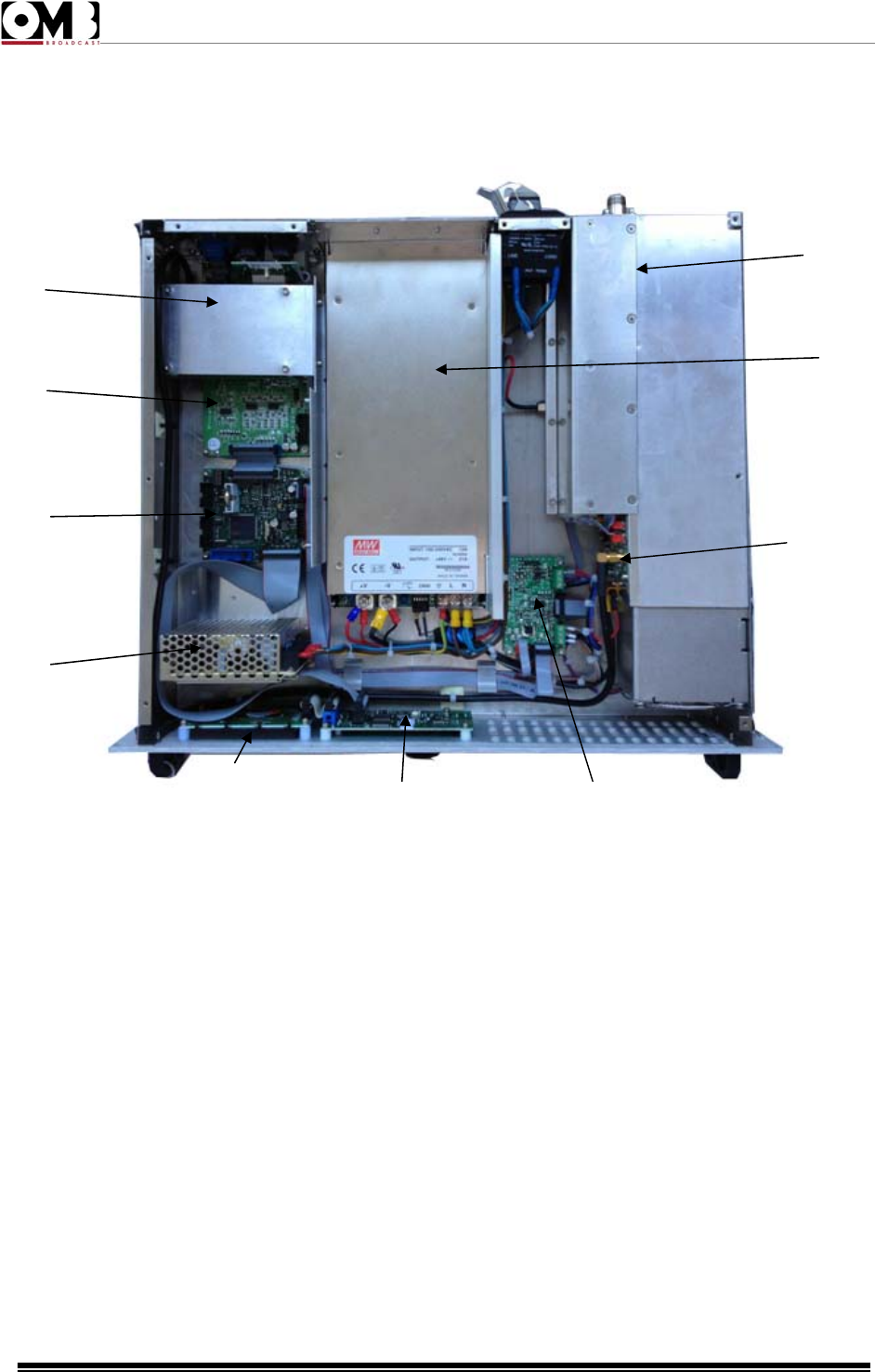
FM Transmitter
EM 500 DIG PLUS
Technical Manual - v1.0 - April 2012
58
3.1 Internal Modules Location.
Next picture shows an internal view of the EM 500 DIG PLUS transmitter:
Figure 3.1: EM 500 DIG PLUS Internal View
The elements numbered in the previous picture are described next:
1. FM Synthesizer.
2. Main Board.
3. Control Unit Board.
4. Aux. Power Supply.
5. Display Board.
6. Knob Encoder Board.
7. COMPADA, Power supply control and fan speed regulator.
8. 10W Driver Module.
9. Main Power Supply.
10. Power Amplifier Block.
11. Stereo Coder (Optional).
5 6 7
1
2
3
4
10
9
8
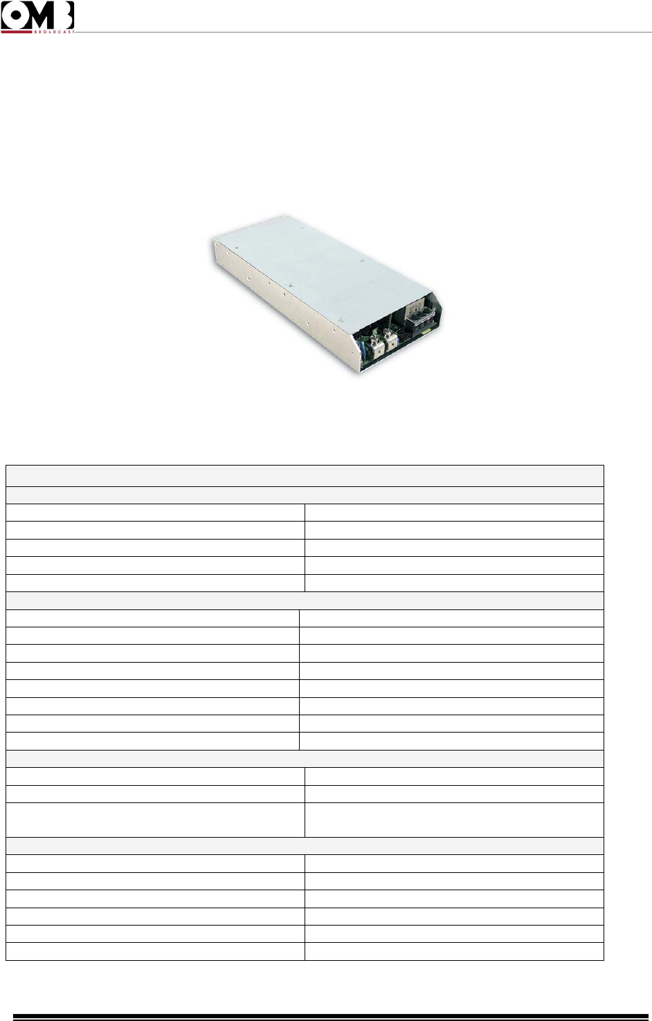
FM Transmitter
EM 500 DIG PLUS
Technical Manual - v1.0 - April 2012
59
3.1.1 Power Supply
The FMA 500 HE uses an AC/DC high performance power supply, to provide voltage to the
different parts that make up the device.
Figure 3-1.. Power Supply 1000-48
These are the technical features for the power supplies we use in the Power Amplifier:
TECHNICALSPECIFICATIONS
Input
Voltage90‐264VVAC127‐370VDC
Frequency47‐63Hz
Efficiency90%(typical)
ACCurrent12A/115VAC6A/230VAC(typical)
PowerFactor0.95/230VAC0.98/115VACfullload(typical)
Output
DCVoltage48V
NominalCurrent21A
CurrentRange0‐21A
NominalPower1008W
AdjutabletensionRange150mVp‐p
VoltageTolerance43‐55V
LineRegulation±1.0%
LoadRegulation±0.5%
Alarms
Overload105‐125%nominaloutputpower
Overvoltage56.6‐66.2V
Overtemperature85ºC±5ºCatDiodeO/P
75ºC±5ºCinpowertransistor
General
WorkingTemperature‐20to+60ºC
StorajeTemperature‐40to+85ºC
WorkingHumidity20‐90%HRwithoutcondensation
Humiditydampness10‐95%HRwithoutcondensation
Dimmensions295x127x41mm
Weight1.95kg
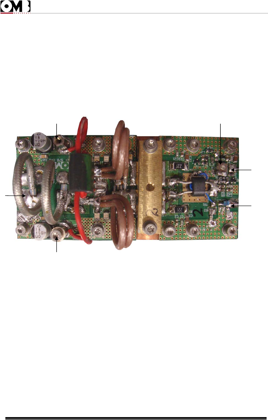
FM Transmitter
EM 500 DIG PLUS
Technical Manual - v1.0 - April 2012
60
3.1.2 600W FM AMPLIFIER MODULE
The amplifier module has been developed using a capsule with two MOSFET designed for its
class B push-pull operation. This module is able to deliver an output power of 600W. It is powered
by a voltage of +48V delivered by the switching power supply of the equipment. In order to avoid
any interference or the propagation of the RF signal across the rest of the equipment producing
EMI radiation, the supply of these modules is made through pass-wall filters and a choke.
The transistors are polarized by an external BIAS Regulator, which set a fixed voltage polarization
value of 8V. This voltage is then internally adjusted to the necessary value for the transistor by
means of the R10 (1) adjustment.
Figure 2-8: RF 600W RF Amplifier Module
Elements numbered in the previous figure are:
1. R10. Potentiometer used for the adjustment of the transistor voltage.
2. Bias connection.
3. RF Input connection.
4. VDD Supply.
5. RF Output connection.
1
2
3
4
5
4
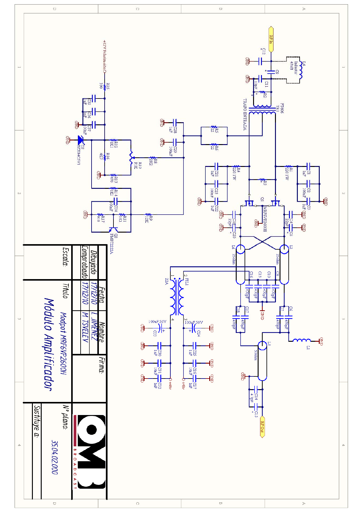
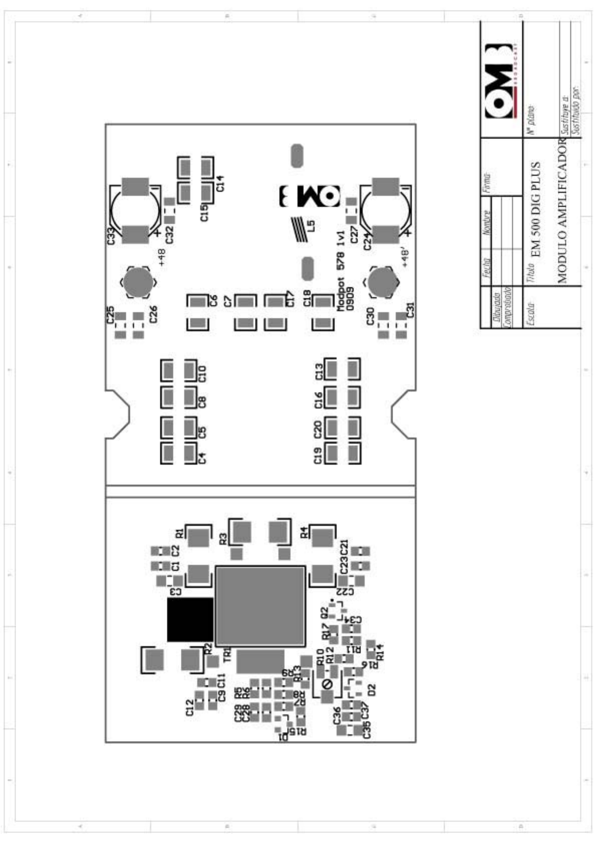
FM Transmitter
EM 500 DIG PLUS
Technical Manual - v1.0 - April 2012
61
600WFMAmplifierModule
DESCRIPTIONREFERENCEQUANTITY
SMD0805±10%50V1nFCapacitorC1,C21,C28,C364
SMD0805±10%50V100nFCapacitorC2,C23,C29,C34,C375
SMD1206±10%50V1uFCapacitorC3,C22,C353
SMD1210±10%200V22pFCapacitorC4,C192
SMD1210±10%500V150pFCapacitorC6,C7,C17,C184
SMD1210±10%200V470pFCapacitorC8,C10,C13,C164
SMD0805±5%50V47pFCapacitorC91
SMD0805±5%50V6.8pFCapacitorC121
SMD1210±10%500V15pFCapacitorC141
SMD≥50VD8mm100uFelectrolytic
Capacitor
C24,C332
SMD1206±10%100V1nFCapacitorC25,C27,C30,C324
SMD1206±10%100V10nFCapacitorC26,C312
SMDSOT235.1VBZX84C5V1ZenerDiodeD21
BinocularFerriteFT8FIL11
InductorDext8mm7vueltDcable0.8‐1mm
enamelwire
L11
25ΩCoaxialline L2,L62
50ΩCoaxialline L31
NPNSMDSOT23PMBT2222ATransistorQ21
SMD25122W10ResistanceR1,R42
SMD2512(270R2W=2x560R1W)
Resistance
R22
SMD25122W56RResistanceR31
SMD08050.125W±5%22ResistanceR5,R62
SMD08050.125W±5%2K2ResistanceR81
SMD08050.125W±5%12KResistanceR91
Singleturn1K3/8’’1kΩPotentiometerR101
SMD08050.125W±5%5K1ResistanceR111
SMD08050.125W±5%3K9ResistanceR121
SMD08050.125W±5%270ResistanceR131
SMD08050.125W±5%1K1ResistanceR141
SMD08050.125W±5%390ResistanceR151
SMD08050.125W±5%4K7ResistanceR161
SMD08050.125W±5%910ResistanceR171
InputtransformerTR11

FM Transmitter
EM 500 DIG PLUS
Technical Manual - v1.0 - April 2012
62
600WFMAmplifierModule
DESCRIPTIONREFERENCEQUANTITY
Ferriteforinputtransformer TR1’2
Transformerprimarycopperwire
7xD0.2mmTeflon1turn
TR1’’1
Transformersecondarysilveredcopper
wireD1.5mm
TR1’’’1
Hex.Separ.H‐H10mmBrass‐NickelH1,H22
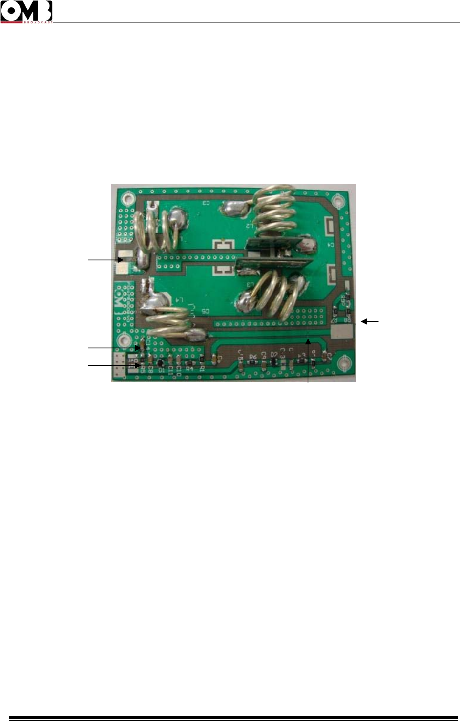
FM Transmitter
EM 500 DIG PLUS
Technical Manual - v1.0 - April 2012
63
3.1.3 800W Filter
The low pass filter attenuates the harmonics outside band II, at -70dbc levels, being placed in the
drainage circuit of the output transistors.
A directional coupler is also included in this section. It provides forward and reflected proportional
Vdc voltages depending forward and reflected power. It takes a RF sample not demodulated
(MONITOR RF) too, in order to be externally used to make measures with a modulation monitor
or frequency-meter. This signal is present at the BNC female connector located in the back panel.
Figure 3-3 800W Filter
These are the numbered elements of the filter in the previous image:
1 – Reflected Power Detector.
2 – Direct Power Detector.
3 – Directional Coupler.
4 – RF Input.
5 – RF Output.
3
2
1
5
4
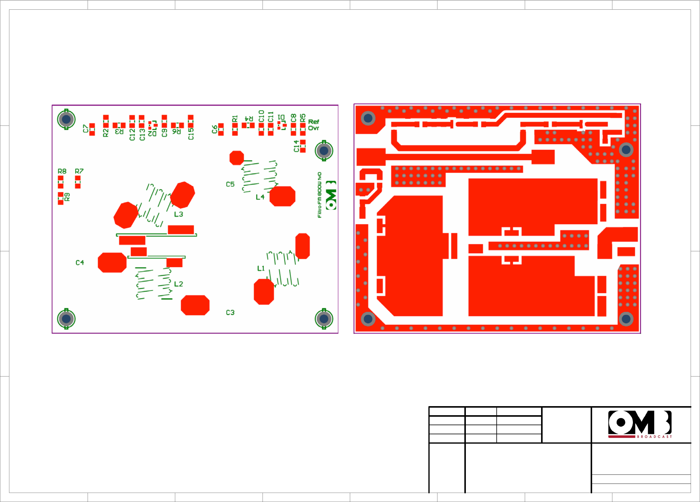
1
1
2
2
3
3
4
4
5
5
6
6
7
7
8
8
D D
C C
B B
A A
Drawn
Checked
Date Name Signature:
Scale: Title Drawing nr:
Replace:
Replaced with:
FILTRO 800 W

FM Transmitter
EM 500 DIG PLUS
Technical Manual - v1.0 - April 2012
64
800WFilter
DESCRIPTIONREFERENCEQUANTITY
PCBfilter800W1v0PCB1
PCB7.5pFPCBC11
PCB11.7pFPCBC21
SMDCapacitor12061nFC6,C7,C8,C9,C14,C15 6
SMDCapacitor120610pFC10,C122
SMDDiodeSOT‐23HSMS2800D1,D22
CoilL1,L2,L3,L44
SMDResistor1206100RR1,R2,R3,R44
SMDResistor120651RR7,R8,R93
SMDResistor12061kR5,R62
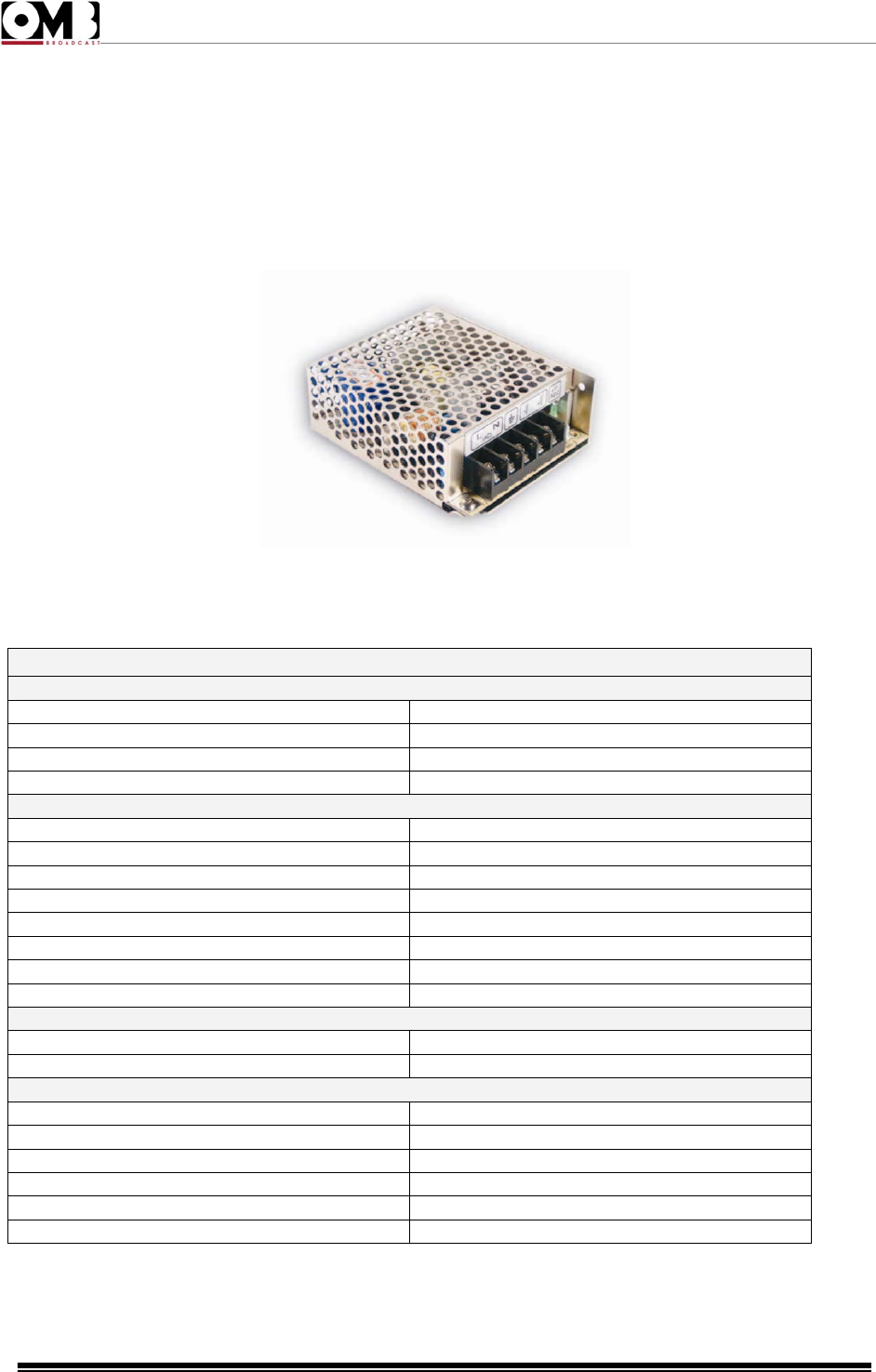
FM Transmitter
EM 500 DIG PLUS
Technical Manual - v1.0 - April 2012
65
3.1.4 Auxiliary Power Suppy
The FMA 500 HE uses an AC/DC power supply, to provide auxiliary voltage to the different
parts that make up the device.
Figure 3-4. RD 3513 Power Supply
TECHNICALSPECITICATIONS
Input
Voltage88‐264VAC125‐373VDC
Frecuency47‐63Hz
Eficiency80%(tipical)
ACConsumtion0.8A/115VAC0.55A/230VAC(tipical)
Output
DCVoltage13.5V
NominalCurrent1.3A
CurrentRange0.3–2ª
NominalPower35.1W
AdjustableVoltageRange120mVp‐p
VoltageTolerance11.5–15.5V
Lineregulation±0.5%
LoadRegulation±3.0%
Alarms
Overload110–150%potenciadesalidanominal
Overvoltage56.6‐66.2V
General
WorkingTemperature‐25a+70ºC
StorajeTemperature‐40a+85ºC
WorkingHumidity20‐90%HRwithoutcondensation
Humiditydampness10‐95%HRwithoutcondensation
Dimmensions98x82x36mm
Weight0.3kg
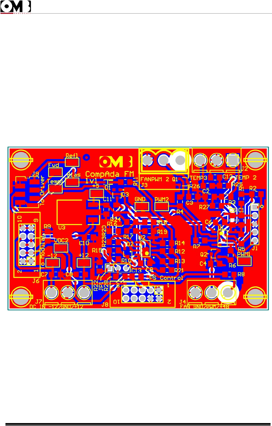
FM Transmitter
EM 500 DIG PLUS
Technical Manual - v1.0 - April 2012
66
3.1.5 Compada Board.
This card has the following functions:
• Connects the +/-12V power supply to modulator.
• Controls power supply level voltage of the RF power stage.
• It helps to improve the device’s efficiency in the whole working power range, reducing the
supply voltage at the same time the output power reduces.
• This function can be set according to the type of power supply in use, according to the
transmitter.
• Controls the speed fans in FM amplifiers in relation to their own temperature. By this, the
device consumes less in airing and the acoustic noise decreases, improving the efficiency.
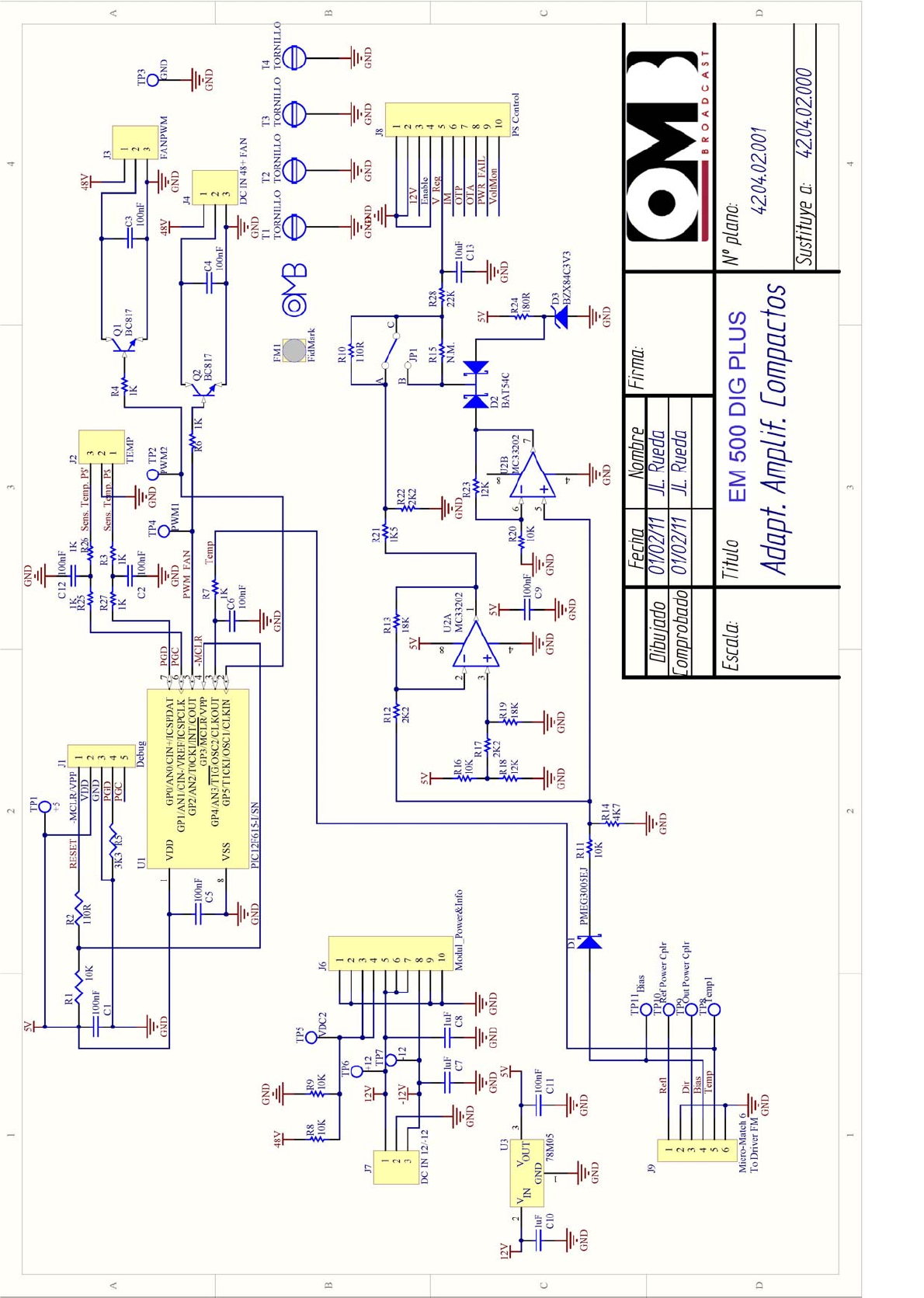
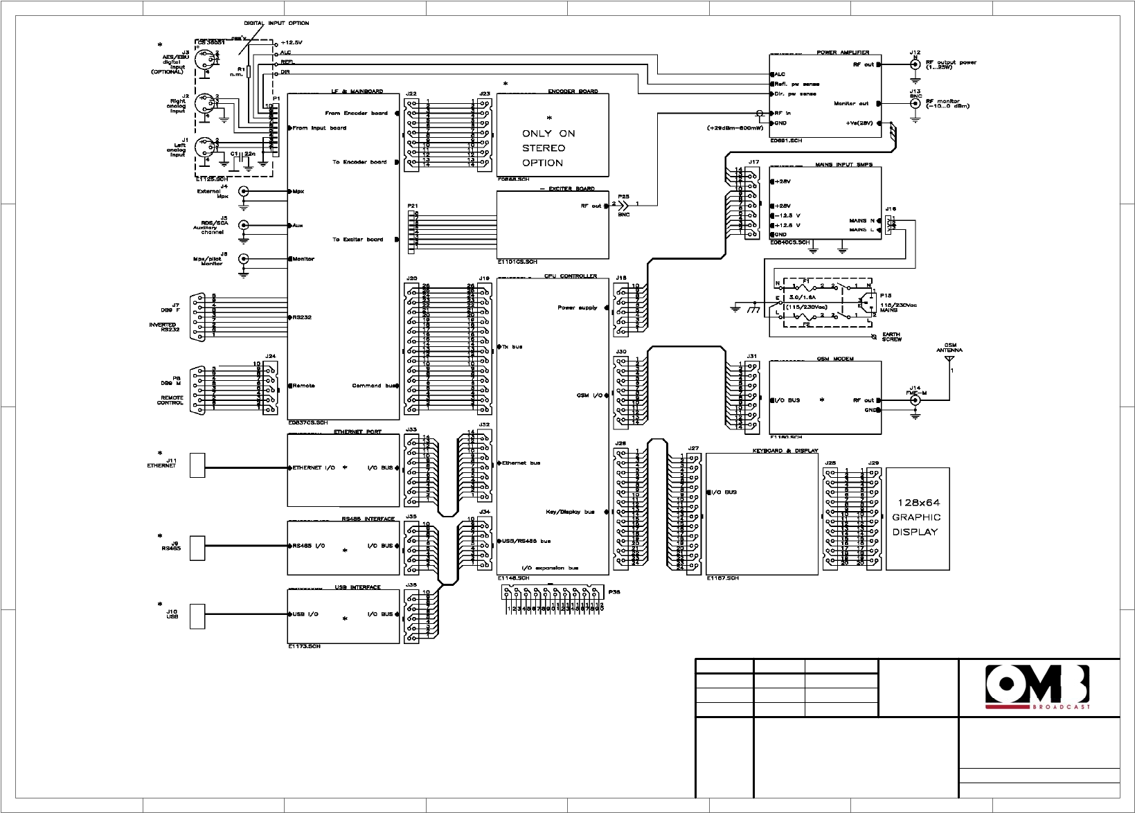
1
1
2
2
3
3
4
4
5
5
6
6
7
7
8
8
D D
C C
B B
A A
Dibujado
Comprobado
Fecha Nombre Firma:
Escala: Titulo Nº plano:
Sustituye a:
Sustituido por:
EM 500 DIG PLUS
General Wiring
Diagram
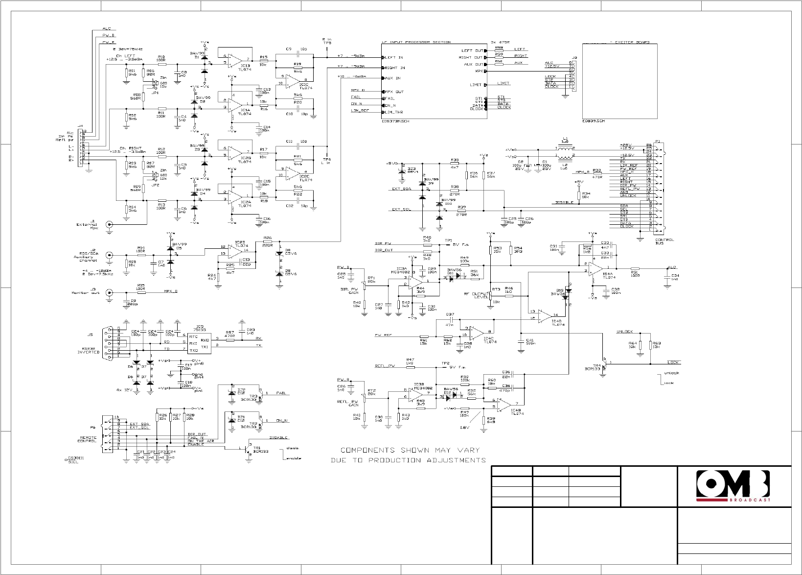
1
1
2
2
3
3
4
4
5
5
6
6
7
7
8
8
D D
C C
B B
A A
Dibujado
Comprobado
Fecha Nombre Firma:
Escala: Titulo Nº plano:
Sustituye a:
Sustituido por:
EM 500 DIG PLUS
Main Board 1/2
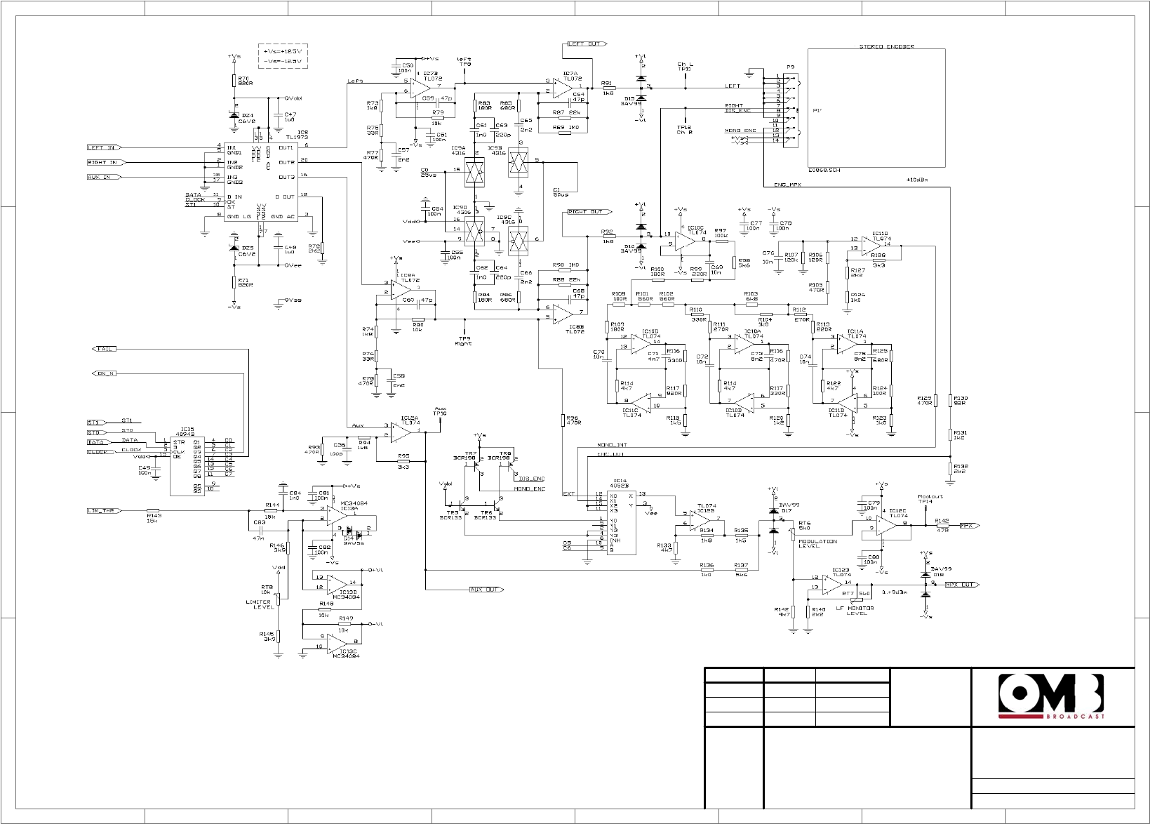
1
1
2
2
3
3
4
4
5
5
6
6
7
7
8
8
D D
C C
B B
A A
Dibujado
Comprobado
Fecha Nombre Firma:
Escala: Titulo Nº plano:
Sustituye a:
Sustituido por:
EM 500 DIG PLUS
Main Board 2/2
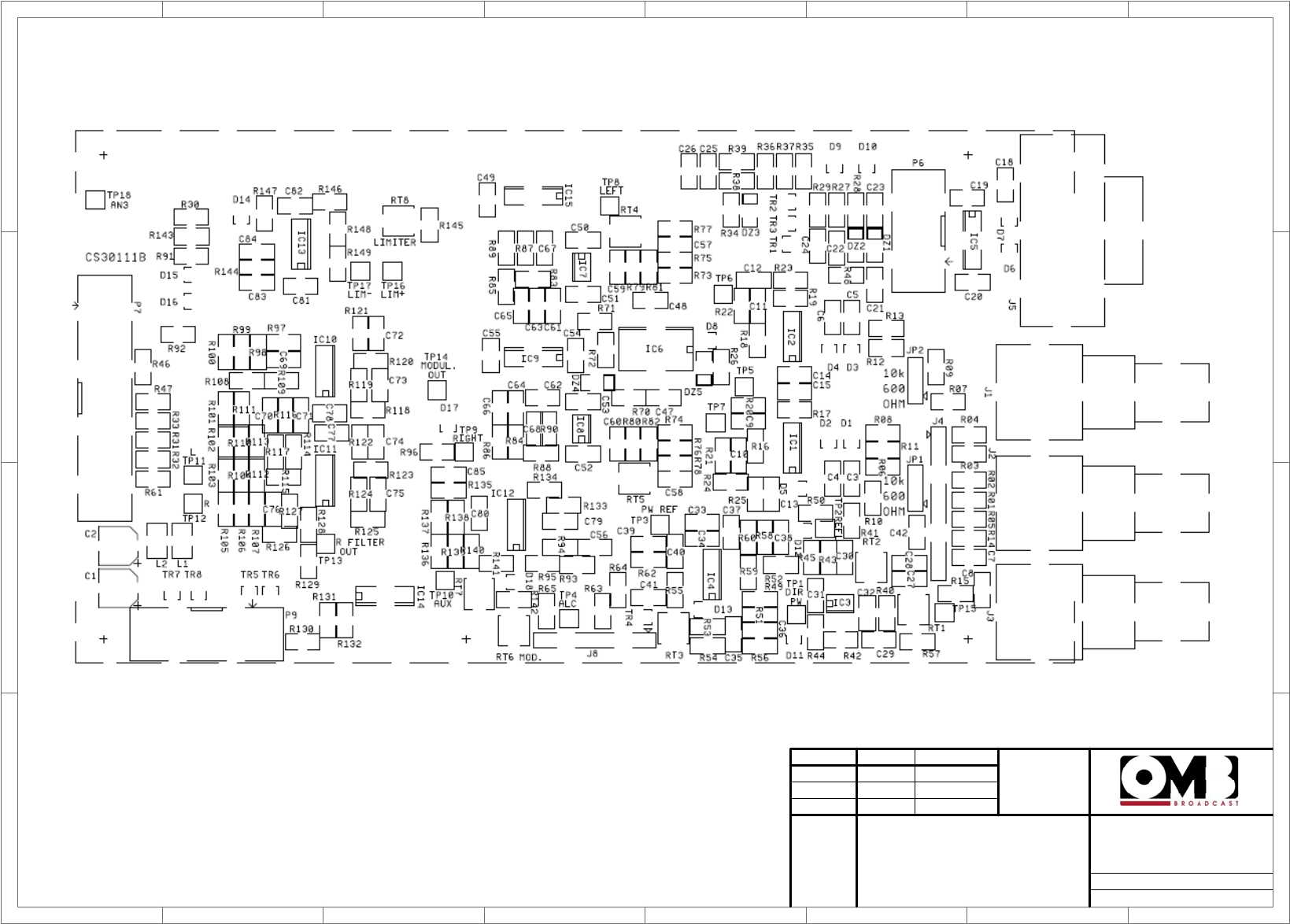
1
1
2
2
3
3
4
4
5
5
6
6
7
7
8
8
D D
C C
B B
A A
Dibujado
Comprobado
Fecha Nombre Firma:
Escala: Titulo Nº plano:
Sustituye a:
Sustituido por:
EM 500 DIG PLUS
Main Board
Layout
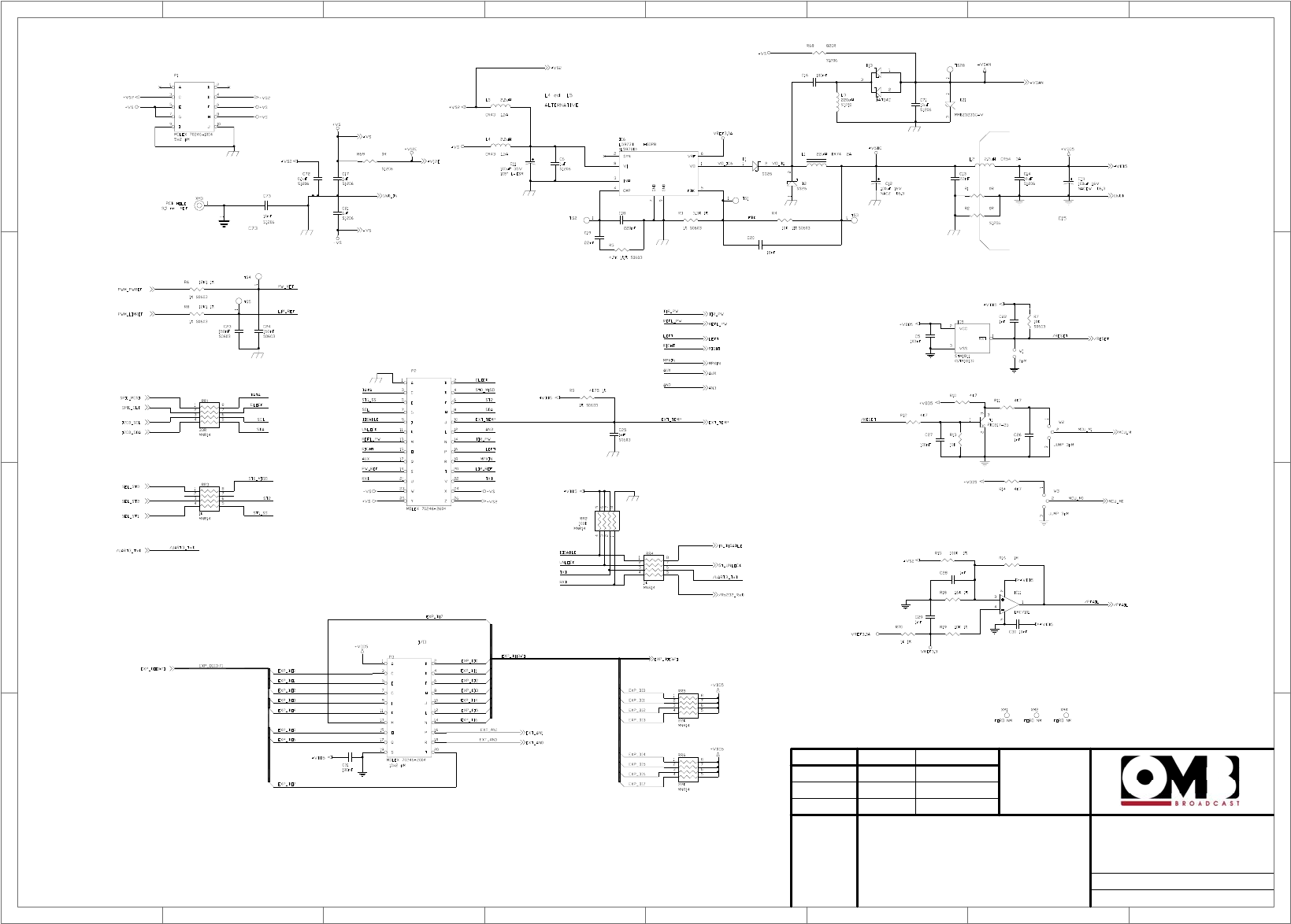
1
1
2
2
3
3
4
4
5
5
6
6
7
7
8
8
D D
C C
B B
A A
Dibujado
Comprobado
Fecha Nombre Firma:
Escala: Titulo Nº plano:
Sustituye a:
Sustituido por:
EM 500 DIG PLUS
Controller Board 1/3
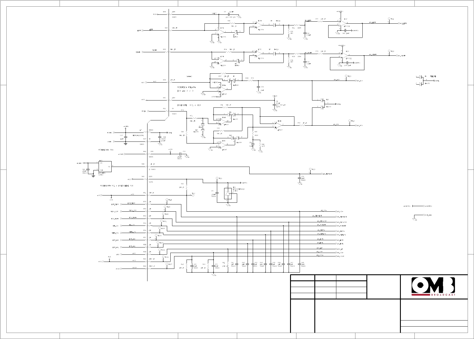
1
1
2
2
3
3
4
4
5
5
6
6
7
7
8
8
D D
C C
B B
A A
Dibujado
Comprobado
Fecha Nombre Firma:
Escala: Titulo Nº plano:
Sustituye a:
Sustituido por:
EM 500 DIG PLUS
Controller Board 2/3
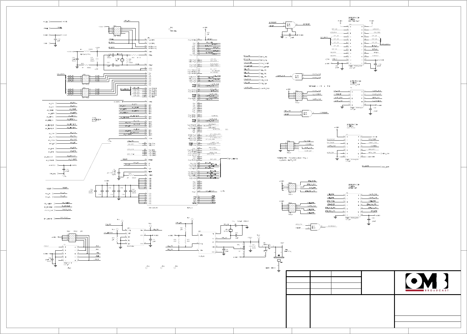
1
1
2
2
3
3
4
4
5
5
6
6
7
7
8
8
D D
C C
B B
A A
Dibujado
Comprobado
Fecha Nombre Firma:
Escala: Titulo Nº plano:
Sustituye a:
Sustituido por:
EM 500 DIG PLUS
Controller Board 3/3
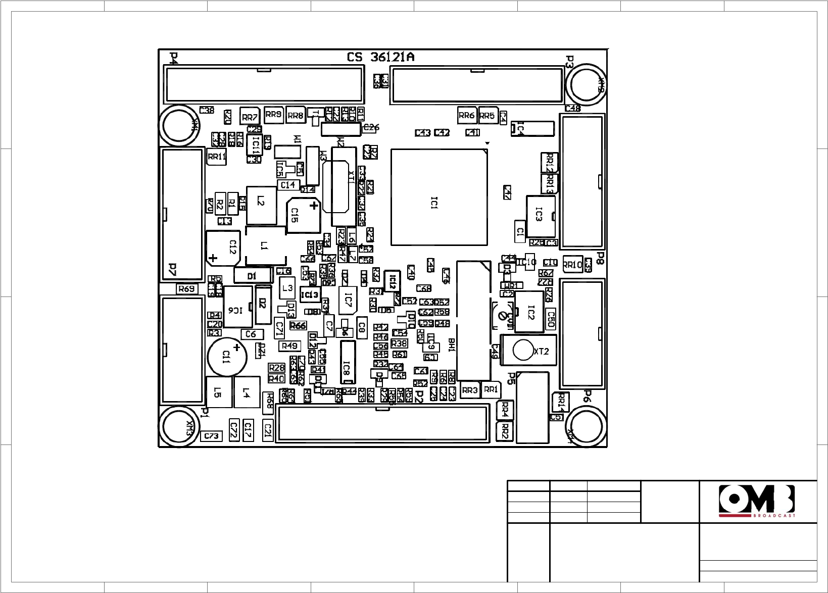
1
1
2
2
3
3
4
4
5
5
6
6
7
7
8
8
D D
C C
B B
A A
Dibujado
Comprobado
Fecha Nombre Firma:
Escala: Titulo Nº plano:
Sustituye a:
Sustituido por:
EM 500 DIG PLUS
Controller Board Layout
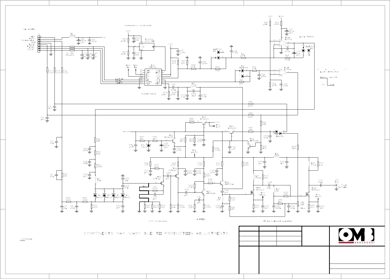
1
1
2
2
3
3
4
4
5
5
6
6
7
7
8
8
D D
C C
B B
A A
Dibujado
Comprobado
Fecha Nombre Firma:
Escala: Titulo Nº plano:
Sustituye a:
Sustituido por:
EM 500 DIG PLUS
FM Exciter
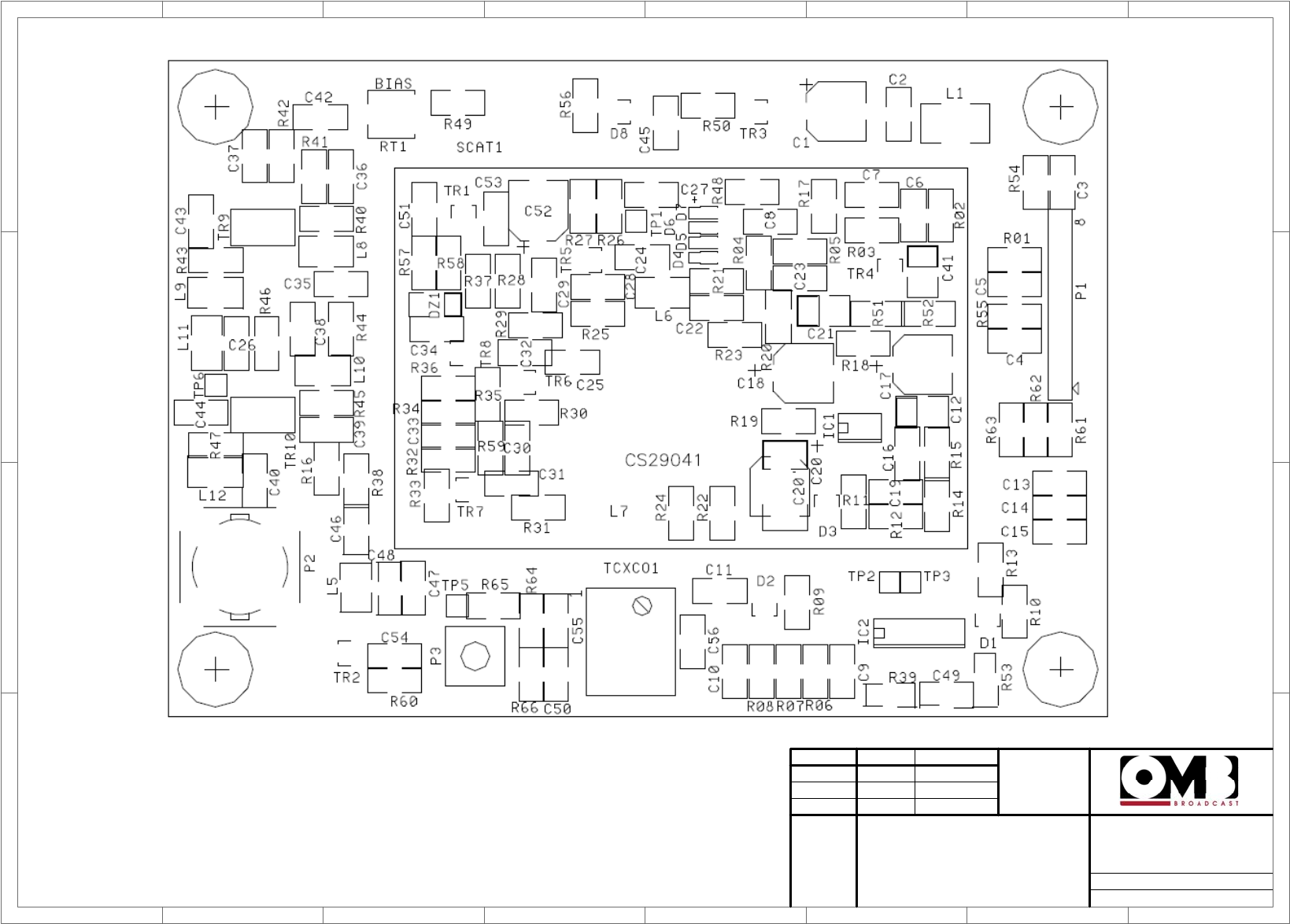
1
1
2
2
3
3
4
4
5
5
6
6
7
7
8
8
D D
C C
B B
A A
Dibujado
Comprobado
Fecha Nombre Firma:
Escala: Titulo Nº plano:
Sustituye a:
Sustituido por:
EM 500 DIG PLUS
FM Exciter
Layout
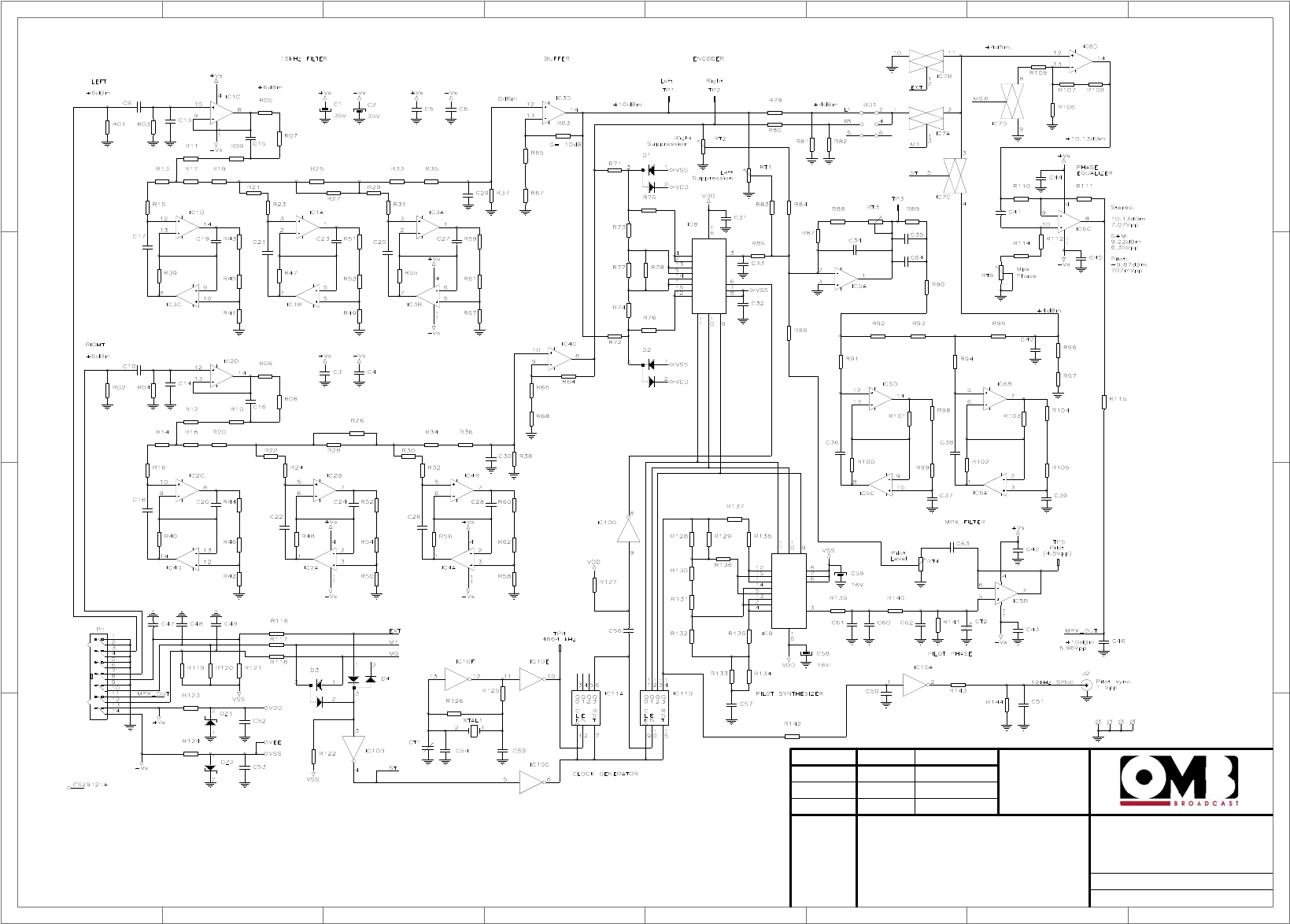
1
1
2
2
3
3
4
4
5
5
6
6
7
7
8
8
D D
C C
B B
A A
Dibujado
Comprobado
Fecha Nombre Firma:
Escala: Titulo Nº plano:
Sustituye a:
Sustituido por:
EM 500 DIG PLUS
Stereo Encoder
(OPTIONAL)
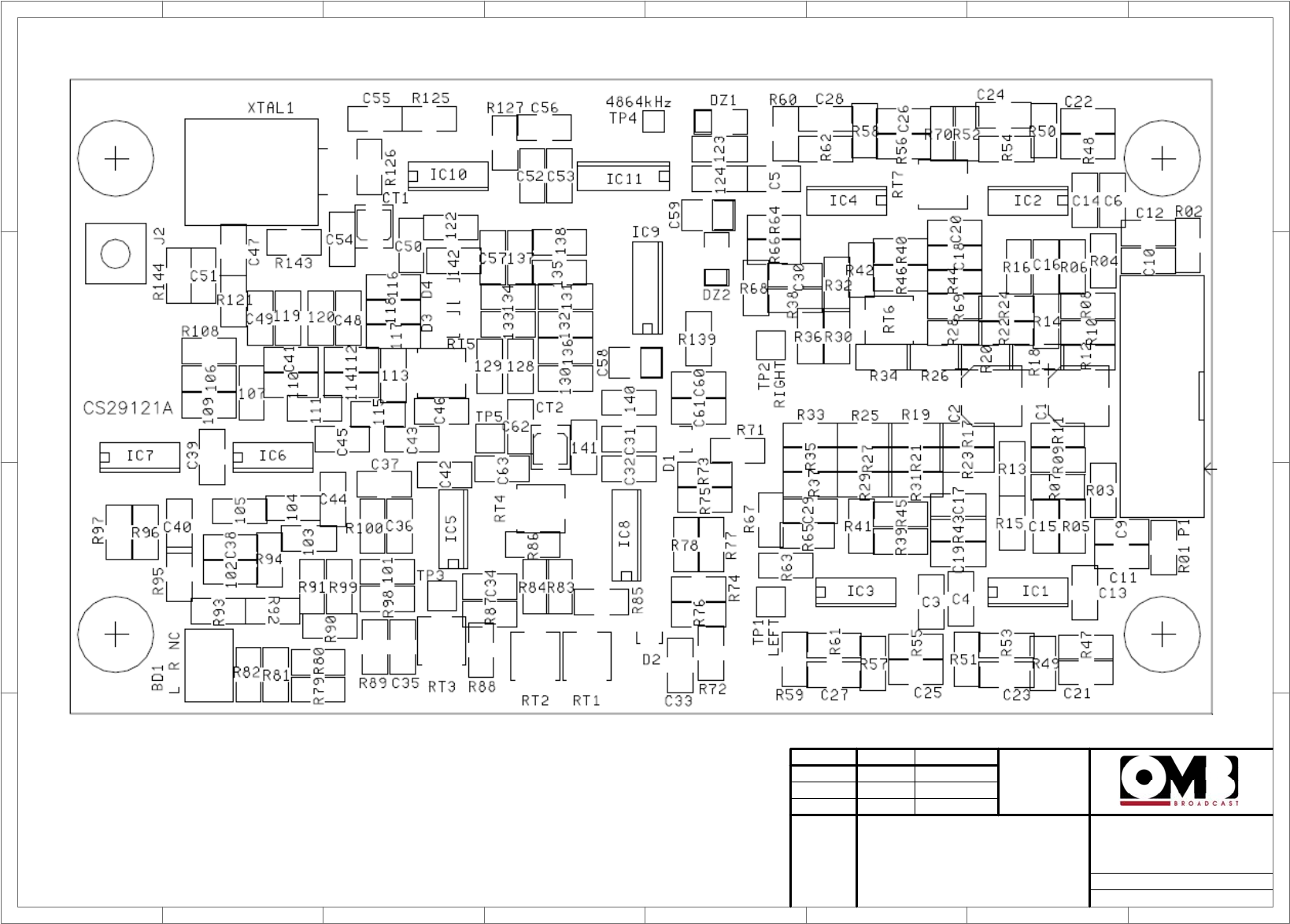
1
1
2
2
3
3
4
4
5
5
6
6
7
7
8
8
D D
C C
B B
A A
Dibujado
Comprobado
Fecha Nombre Firma:
Escala: Titulo Nº plano:
Sustituye a:
Sustituido por:
EM 500 DIG PLUS
Stereo Encoder
Layout (OPTIONAL)
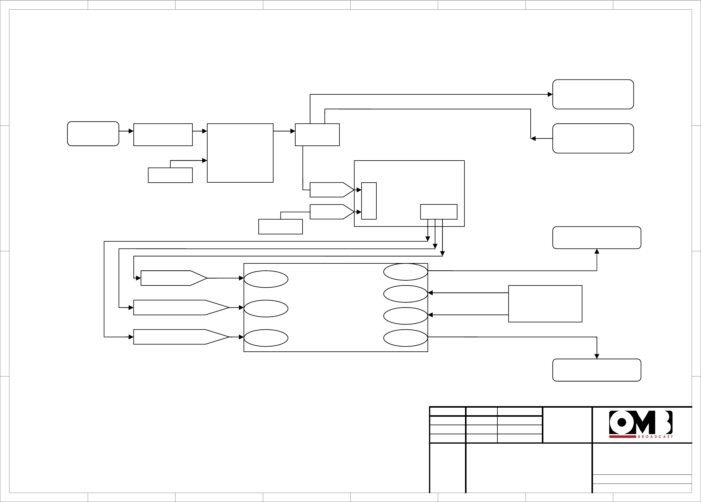
1
1
2
2
3
3
4
4
5
5
6
6
7
7
8
8
D D
C C
B B
A A
Drawn
Checked
Date Name Signature:
Scale: Title Drawing nr:
Replace:
Replaced with:
Switch
Auxiliary AC
power supply
DC/DC converter
Relay
Rectifier bridge
25Amps/600V
20Amps fuse
P1
GND
+12Vcc output main
-12Vcc output main
+48Vcc from AC
power supply
+48Vcc Output
main
P2
+48Vcc
GND
P2 1-2
g
nd
P2 5-6-7 +12Vdc
P2 8 -12Vdc
P1 3
P1 4
A2
A1
11
1
2
2
2
24
2
1
EM 500 HE DIG PLUS
COMPACT
48Vcc (OPTIONAL)

FM Transmitter
EM 500 DIG PLUS
Technical Manual - v1.0 - April 2012
67
R&TTE DIRECTIVE 1999/5/CE
Declaration of Conformity
English: This equipment is in compliance with the essential requirements
and other relevant provisions of Directive 1999/5/EC
Deutsch: Dieses Gerät entspricht den grundlegenden Anforderungen und
den weiteren entsprechenden Vorgaben der Richtlinie 1999/5/EU.
Dansk: Dette udstyr er i overensstemmelse med de væsentlige krav og
andre relevante bestemmelser i Directiv 1999/5/EF.
Español: Este equipo cumple con los requisitos esenciales asi como con
otras disposiciones de la Directiva 1999/5/EC.
'Ελληνας Αυτός ο εξοπλισµóς συµµορφώνεται µε τις ουσιώδεις απαιτήσεις και
τις λοιπές διατάξεις της Οδηγίας 1999/5/ΕΚ
Français: Cet appareil est conforme aux exigences essentielles et aux autres
dispositions pertinentes de la Directive 1999/5/EC.
Íslenska: Þessi búnaður samrýmist lögboðnum kröfum og öðrum ákvæðum
tilskipunar 1999/5/ESB.
Italiano: Questo apparato é conforme ai requisiti essenziali ed agli altri
principi sanciti dalla Direttiva 1999/5/EC.
Nederlands: Deze apparatuur voldoet aan de belangrijkste eisen en andere
voorzieningen van richtlijn 1999/5/EC.
Norsk: Dette utstyret er i samsvar med de grunnleggende krav og andre
relevante bestemmelser i EU-directiv 1999/5/EC.
Português: Este equipamento satisfaz os requisitos essenciais e outras
provisões da Directiva 1999/5/EC.
Suomalainen: Tämä laite täyttää direktiivin 1999/5/EY oleelliset vaatimukset ja
on siinä asetettujen muidenkin ehtojen mukainen.
Svenska: Denna utrustning är i överensstämmelse med de väsentliga kraven
och andra relevanta bestämmelser i Direktiv 1999/5/EC.
The following CE mark is affixed to the equipment:
The identification number of the Notified Body who certified the product might change.
The use of this equipment may be restricted to certain frequencies and may require a
license for operation. For more details, contact with your nearest local administration.
FM Transmitter
EM 500 DIG PLUS
Technical Manual - v1.0 - April 2012
68
Legal Notice:
According to the European directives, 2002/96/CE and 2003/108/CE, it is forbidden to trash Waste
Electrical and Electronic Equipment (WEEE) products along with normal wastes. The equipment
classified cannot be disposed as urban waste but it must be sent to the specific collecting centres prepared
by the municipal government and they will arrange the separate collection of WEEE.
The under-reproduced symbol indicates that the unit at the end of its life has to be considered WEEE
(Waste of Electrical and Electronic Equipment).
Toxic materials – Product and environmental safety
Some components used in the construction of this equipment contain
Beryllium Oxide (BeO). The product is entirely safe provided that the BeO
discs are not damaged. Do not disassemble, crush or dispose of this product
with normal waste. All persons who handle, use or dispose of this product
should be aware of its nature and of the necessary safety precautions. After
use, dispose of as chemical or special waste according to the regulations
applying at the location of the user. It must never be thrown out with the
general or domestic waste.

FM Transmitter
EM 500 DIG PLUS
Technical Manual - v1.0 - April 2012
69
INTENTIONALLY BLANK