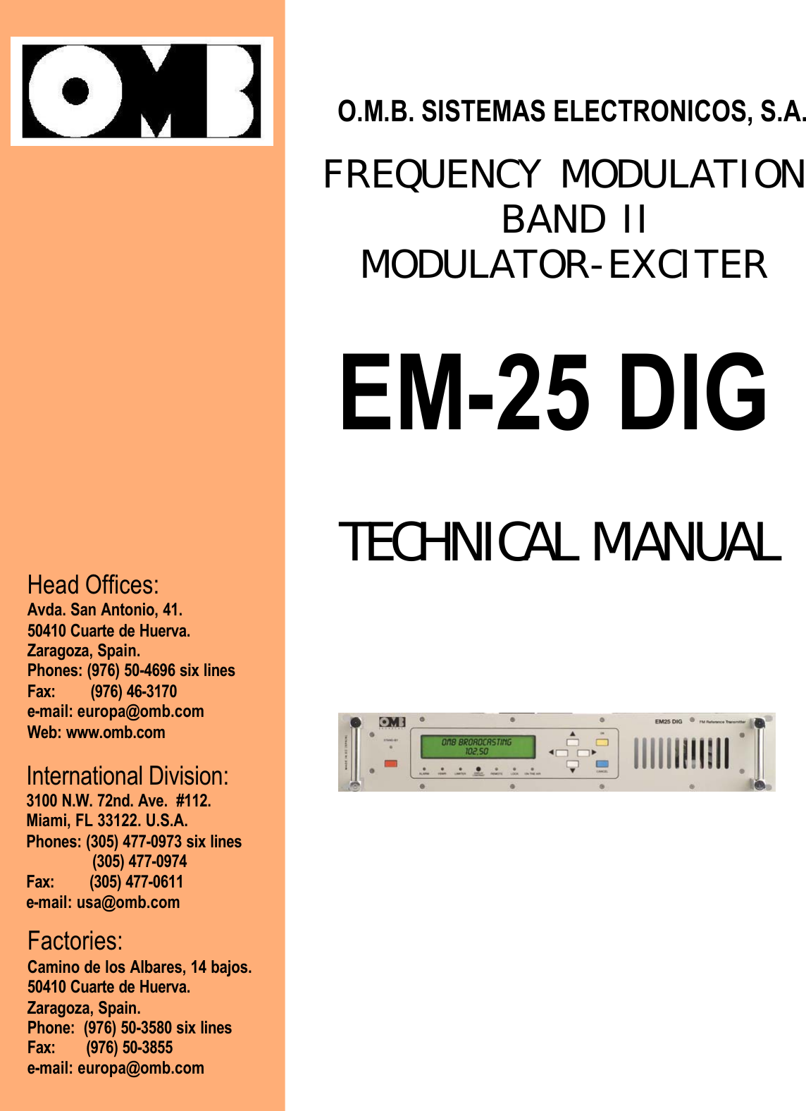
Transamerica Broadcasting EMDIG25 25 Watt FM Broadcast Transmitter User Manual Frontpage

Transamerica International Broadcasting Inc 25 Watt FM Broadcast Transmitter Frontpage

User Manual

                                                                            O.M.B. SISTEMAS ELECTRONICOS, S.A.                                 FREQUENCY MODULATION                                     BAND II                                         MODULATOR-EXCITER   EM-25 DIG                                           TECHNICAL MANUAL                                             Head Offices: Avda. San Antonio, 41. 50410 Cuarte de Huerva. Zaragoza, Spain. Phones: (976) 50-4696 six lines Fax:        (976) 46-3170 e-mail: europa@omb.com Web: www.omb.com International Division: 3100 N.W. 72nd. Ave.  #112. Miami, FL 33122. U.S.A. Phones: (305) 477-0973 six lines                (305) 477-0974 Fax:        (305) 477-0611 e-mail: usa@omb.com   Factories: Camino de los Albares, 14 bajos. 50410 Cuarte de Huerva. Zaragoza, Spain. Phone:  (976) 50-3580 six lines Fax:       (976) 50-3855 e-mail: europa@omb.com
.                                                                                                                                                                                          FM BROADCAST MODULATOR/EXCITER EM-25 DIG.                                                                         Limited Warranty Conditions                                                                                                                           I.- About Installation.1.-  Mains Voltage must be kept between ± 10% about its nominal value,  unless  otherwise  specified.     If  were  variations  exceeding  this  tolerance, it will   be indispensableto install a voltage stabilizer system  within station. If transient overvoltages,  due  to electric motors, or  other  devices  of  this sort connected   to  the distribution line,    werepresent,    or if the  distribution  line  is   exposed  to  atmospheric  electrical   discharges,  it  must  be  indispensable  the  installation  of   isolation transformers  and  gaseousdischargers before connecting any equipment within station.2.-  All equipments must be connected to station ground system in order to avoid damage both to equipments and maintenance personnel too. It  is  necessary  to connect adifferential automatic switch (lifesaver) at station.3.-  Some equipments does not include interlock protection for open doors, covers or connectors. In that case, these equipments must be kept in key-locked places, with accessonly to  conveniently qualified personnel  that is previously noticed about not to open doors, covers or connectors  without  disconnecting  station mains switch before performingthis job.4.-  Transmitter equipments NEVER will be operated with output powers over its nominal values, or with signals or input informations others than those specified in its individualcharacteristics.5.-  Ambient temperature inside equipments' room, will accomplish technical specifications of equipments  installed at station lodge. In absence of such specifications, maximumallowable temperatures will  be  from  -5 to + 45 º C for Television equipments, and from 0 to + 40 º C  for Sound Broadcast equipments.6.-  In case of operation at abnormally high or extremely high temperatures (over 30 to 40 º C), it is obligatory to install a forced cooling system that will keep temperature belowits upper limit. In case of operation at abnormally or extremely low temperatures, it will be obligatory to install a  thermostatic controlled heating system for equipment's room.7.-  Both equipment's surroundings and room must be free of dust and dirt. Ambient relative humidity  will  be kept below equipment's extreme specifications. In case of absenceof this specification, allowable  maximum will be 90 % of relative humidity, non-condensing. Average relative humidity will be kept under 70 %, non-condensing.8.-  Every transmission equipment able to radiate some quantity of RF power, must  be  connected  to  a  load or antenna system, suited to its individual specifications, beforebeing energized.9.-  Maximum allowable VSWR in antenna systems both for Television or FM Radio Broadcast operation of a  given transmitter, will be 1.25:1, unless otherwise specified.10.- For those transmitter equipments having power valve amplifiers, and that doesn't has an automatic shutoff cycle, and must be manually turned off, as a first step highvoltage,  or  anode voltage, will be disconnected, keeping forced cooling system working during at least 5 minutes after high voltage disconnection, and only after this time,cooling system & filament voltage can be shutted off. O.M.B.  Sistemas Electrónicos, S.A., is not  responsible of damages to those power valves caused by sudden AC mainsfailures  at station where our equipments are installed.11.- Periodically,  monthly as a  maximum, technical  personnel must visit  station in order  to  perform a   general    equipment maintenance,  unless otherwise specified. Thismaintenance will include output power check, VSWR  of antenna systems, forced cooling or heating systems checks, both for equipments and station itself, including air filterscleaning, measuring of transmission frequency with eventual correction if  necessary,   and will perform a general check of fundamental parameters of equipments. In the eventof    any   important    change in  some  operation parameter, that will require replacement  or readjustment    of  any unit, Customer    MUST CONTACT FIRST WITH O.M.B.SISTEMAS ELECTRONICOS, S.A. BEFORE ANY ATTEMPT TO READJUST OR REPLACE  ANY  COMPONENT OR UNIT INSIDE EQUIPMENTS, IN ORDER TO KEEPVALID THIS WARRANTY.12.- For  equipments  who  are  located  in  fixed racks or cabinets,  those  equipments  must be  effectively  connected, according to International Installations Standards, tostation ground system, whose  total impedance measured to ground can't be higher than 5 ohms. Equipments must be connected to ground system  so that they can be kept outof main discharge path between tower and ground.                                                                                                                           II.- About Transportation.1.-    O.M.B.  Sistemas  Electrónicos,  S.A.  is  not  responsible  of damages and/or  detriments  derived    from  mishandling,  steal,  robbery,  theft  or  vandalism during the  act  oftransportation of equipments to final or intermediate destination.                                                                                                                               III.- About Storage.1.-  O.M.B. Sistemas Electrónicos, S.A. is not responsible of damages and/or detriments derived  from unappropiate storage  of  equipments, within  inadequate  warehouses  oroutdoors, once equipments  are  delivered  to transportist agency.                                                                                                                                   IV.- About Projects.1.-  O.M.B. Sistemas Electronicos, S.A. is not responsible of inadequate use of equipments made  or registered by our Company, accomplishing propagation projects that arenot performed by our Specialists.W-1
.                                                                                                                                                                                          FM BROADCAST MODULATOR/EXCITER EM-25 DIG.                                                                                                                                V.- About Systems.1.-  O.M.B. Sistemas Electrónicos, S.A. is not responsible for performance of those equipments or systems that  are not made, certified or registered by our Company.                                                                                                                             VI.- About Operation1.-   O.M.B.  Sistemas Electrónicos, S.A.  is not responsible of  damages and/or detriments  derived from  inadequate  or negligent operation of equipments made, certified orregistered by our Company, once  those  equipments are operated by  personnel hired and/or employed by Customer.                                                                                                                                   VII.- General.This Warranty covers and protects, during a period of 18 months after start of operations, all equipments made , certified or registered by O.M.B. Sistemas Electrónicos, S.A.,including  its  components    and    units,  against      failures  in  workmanship  that  may  occur  during operation  of  those  equipments,  with  the  exception  of    power  valves  orsemiconductor devices that are covered by its particular Factory's Guarantee. In this case, O.M.B. Sistemas Electrónicos, S.A. only can act as intermediary for negotiation withsuch Factory,  about  accomplishment of individual Guarantees.For Validity of this Warranty, it is indispensable that all Paragraphs,  from  I  to  VI,  be respected by the Customer. Otherwise, this Warranty will be automatically voided.  ThisWarranty is self-activated with the reception by OMB Sistemas Electrónicos, S.A. of the  "Guarantee Activation Manual". returned to OMB by Customer.  If such Document is notreceived, this Warranty will be voided.All repairings or adjustments covered by this Warranty are free of workmanship & materials costs and expenses, but  postage and transportation expenses of equipments andO.M.B. technical personnel & specialists, if required, will  be  carried out by the Customer.                                                                                                                                                                                                            O.M.B. Sistemas Electrónicos, S.A.                                                                                                                                                  W-2
.                                                                                                                                                                                          FM BROADCAST MODULATOR/EXCITER EM-25 DIG. GENERAL SAFETY RECOMMENDATIONSWhen connecting the equipment to the Mains power , please follow these important recommendations: This product is intended to operate from a power source that will not apply more than 10% of the voltagespecified on the rear panel between the supply conductors or between either supply conductor and ground.A protective-ground connection by way of the grounding conductor in the power cord is essential for safeoperation. This equipment is also grounded through the grounding conductor of the power cord. To avoid electricalshock, plug the power cord into a properly wired socket before connecting to the product input or outputterminals. Upon loss of the protective-ground connection, all accessible conductive parts (including parts that mayappear to be insulating) can render an electric shock. Equipment must be throughly connected to Station'sground system before any attempt to connect it to Mains electrical supply. To avoid fire hazard, use only the fuses of correct type, voltage rating, and current rating. Refer fusereplacement to Technical Manual and qualified service personnel. To avoid explosion, do not operate this equipment in an explosive atmosphere. To avoid personal injury, do not remove the product covers or panels. Do not operate the product withoutthe covers and panels properly installed. GOOD PRACTICESIn maintaining the equipment covered in this Manual, please keep in mind the following, standard good practices: When connecting any instrument (wattmeter, spectrum analyzer, etc.) to a high frequency output, use theappropriate attenuator or dummy load to protect the final amplifiers and the instrument input. When inserting or removing printed circuit boards (PCBs), cable connectors, or fuses, always turn off power tothe affected portion of the equipment. After power is removed, allow sufficient time for the power supplies tobleed down before reinserting PCBs. Always use discharge stick when available. When troubleshooting, remember that FETs and other metal-oxide semiconductor (MOS) devices may appeardefective because of leakage between traces or component leads on the printed circuit board. Clean the printedcircuit board and recheck the MOS device before assuming it is defective.                When replacing  MOS devices,  follow standard  practices to  avoid damage  caused by  static charges  andsoldering. When removing components from PCBs (particularly ICs), use care to avoid damaging PCB traces.                                                                                         FA-1
.                                                                                                                                                                                          FM BROADCAST MODULATOR/EXCITER EM-25 DIG.                        FIRST AID IN CASE OF ELECTRICAL SHOCKIf someone seems unable to free himself while receiving an electric shock, turn power off before rendering aid. Amuscular spasm or unconsciousness can make a victim unable to free himself from the electrical power.If power  cannot  be  turned  off  immediately,  very carefully  loop  a  length of dry non-conducting material (suchas a rope, insulating material, or clothing) around the victim and pull him free of the power. Carefully avoid touchinghim or his clothing until free of power. EMERGENCY RESUSCITATION TECHNIQUEStep 1Check the victim for unresponsiveness. If there is no response, immediately  call  formedical assistance, and then return to the person.Step 2Position the person flat on their back. Kneel  by their side  and place one hand on theforehead and the other under the chin. Tilt the head back and lift the chin until teeth almosttouch. Look and listen for breathing.Step 3If not breathing normally, pinch the nose and cover the mouth with yours. Give two fullbreaths. The person's chest will rise if you are giving enough air.           FA-2DO NOT TOUCH VICTIM OR HIS CLOTHING BEFOREPOWER IS DISCONNECTED OR YOU CAN ALSOBECOME A SHOCK VICTIM
.                                                                                                                                                                                          FM BROADCAST MODULATOR/EXCITER EM-25 DIG.Step 4Put the fingertips of your hand on the Adam's apple, slide them into the groove next to thewindpipe. Feel for a pulse. If you can not feel a pulse or are unsure, move on to the nextstep.Step 5Position your hands in the center of the chest between the nipples. Place one hand on top ofthe other.Step 6Push down firmly two inches. Push on chest 15 times.CONTINUE WITH TWO BREATHS AND 15 PUMPS UNTIL HELP ARRIVES.                            TREATMENT FOR BURNS Continue treating victim for electrical shock. Check for points of entry and exit of current. Cover burned surface with a clean dressing. Remove all clothing from the injured area, but cut around any clothing that adheres to the skin and leave it inplace. Keep the patient covered, except the injured part, since there is a tendency to chill.      Splint all fractures. (Violent muscle contractions caused by the electricity may result in fractures.) Never allow burned surfaces to be in contact with each other, such as: areas between the fingers or toes, theears and the side of the head, the undersurface of the arm and the chest wall, the folds of the groin, and similarplaces.. Transport as soon as possible to a medical facility.                                                                                              FA-3
.                                                                                                                                                                                          FM BROADCAST MODULATOR/EXCITER EM-25 DIG.      FREQUENCY-MODULATION BAND II MODULATOR / EXCITER                                       87.5-108.0 MHzEM-25 DIG                         TABLE OF CONTENTS                         Description                                                                                 PageChapter I.     Introduction. General Description...............................................................................................     1Chapter II.    Technical Specifications .............................................................................................................     8Chapter III.   Description of Modules & Units ... ..............................................................................................    10                      3.1.- Introduction .......................................................................................................................    10                      3.2.- Audio Processor  ...............................................................................................................    10                      3.3.- Stereo Generator (Optional)...............................................................................................    12                      3.4.- Synthesized Channel Oscillator ........................................................................................     12                      3.5.- RF Power Amplifier ...........................................................................................................     13                      3.6.- Microcontroller & Display ...................................................................................................    14                      3.7.- Switching Power Supply ....................................................................................................     15Chapter IV.  Installation, Operation  and Maintenance.....................................................................................     17                      4.1.- Introduction ........................................................................................................................      17                      4.2.- System Connection ...........................................................................................................      17                      4.3.-Audio Baseband Presets and Connections ........................................................................     19                      4.4.- Operation ............................................................................................................................     23                      4.5.- Commands & Programming ...............................................................................................     25                      4.6.- Service and Maintenance ...................................................................................................     38 Chapter V.  Schematics & Diagrams ..............................................................................................................      39                                  Document: Frequency Modulation Band II R.F. Modulator/Exciter EM-25 DIG. Technical Manual.                                 Version: 2.0E                                           Reference: EM25DIG.0E                 Date: November, 2001                                                  Made by: Fernando A. Alvarez. B.SC.E.E. Electronics & Telecommunications Engineer.                                                     Copyright: 2001. O.M.B. Sistemas Electrónicos, S.A. / O.M.B. America Division.                                                                                                    All Rights Reserved.            This Manual contains information that is exclusive property of aforementioned Company. Any type of unauthorized reproduction             and/or distribution is forbidden. This Manual does not replaces the professional advise of Engineers or Lawyers.   It is delivered              "as is" , intended  to  be used  as orientative reference. This  Manual  can  be  submitted  to  changes  without  previous notice.            Customer  must  check  first  the  updating status of this book before making use of it, calling OMB Sistemas Electrónicos, S.A.             to be properly oriented by our qualified Specialists.                                                                                     Page  I-1
.                                                                                                                                                                                          FM BROADCAST MODULATOR/EXCITER EM-25 DIG.      FREQUENCY-MODULATION BAND II MODULATOR / EXCITER                                           87.5-108.0 MHzEM-25 DIG                                                                 Chapter I.                                                       INTRODUCTION.  GENERAL DESCRIPTION.1.1.- Introduction:The OMB 20/30 DIG PRO series transmitters are the result of experience gained by OMB during years of producingFM broadcast equipment, transmitters, stl and stereo encoders. These  transmitters  were  specifically  designed  tocomply with the latest international standards and the requirements of advanced broadcasters, meeting tighter spe-cifications than usually required, at an affordable cost.Great care went into producing a Hi-Fi-quality modulated signal, with low residual  noise and distortion. The RFsignal is also free from spurious and harmonic components to a higher degree than required by CCIR, European,USA and most other national standards.  To obtain this outstanding performance, OMB strongly recommend to relyon qualified personnel to install and verify the equipment which makes up the radio station, i.e. the transmitter, thepossible stl and power amplifier, the corresponding antennas, cables and connectors. This will assure to achievethe best performance and stability in time. To this aim, OMB especially recommend that their equipment should notbe tampered with by unskilled personnel and its after-sale service is available to customers for any technicalproblem. Before proceeding to installation, please carefully read at least the general installation part of this manual,to gain confidence with the equipment.The transmitters are very stable and changes to the internal pre-setting other than frequency and few other optionsare not usually required but, if they are, once again they must be done by skilled personnel, with proper instrumen-tation and service documentation. Improperly tampering with the settings may harm the apparatus or jeopardize theguaranteed performance.THIS  EQUIPMENT  COMPLIES   WITH   ALL   RELEVANT  EMI / EMC  AND  SAFETY  REQUIREMENTS,  ETSIEN300384, ETS300447 AND EN60215 STANDARDS.NO INTERNAL ADJUSTMENT OR PRESETTING IS REQUIRED DURING NORMAL OPERATION.   EQUIPMENTSHALL  BE  PROPERLY  GROUNDED   AND   BE   OPERATED   WITH   ALL   THE  COVERS   CLOSED TOPREVENT ELECTRICAL HAZARDS AND COMPLY WITH EMC STANDARDS.OMB hence recommends for these equipments not to be handled by unskilled personnel, together with antennasystem, transmission lines and the remaining components, both at Transmitters and related equipments and station'santennas system. A good installation, made by skilled and trained personnel will avoid many future troubles duringstation's exploitation process.All the operations described in the Certification of Limited Warranty must be accomplished to have the right of makeany claim concerning this Warranty, having free equipment service by OMB's technical personnel during this firstexploitaition phase of Equipment.                                                                                        Page 1
                      MODULADOR-EXCITADOR DE FM BANDA II MODELO EM-25 DIG                                         1.2.-General Description.  The EM-25 DIG is a 30W rated,direct-synthesis,FM-modulated transmitter.Being digitally controlled,it is extensively on field programmable by front panel or remotely in every respect:frequency,power,channel sensitivity, preemphasis, functioning mode (mono,stereo,external mpx),clock and date and many other parameters without adjusting or substituting any part.A powerful 3-levels password management permits a very high degree of security and privacy as may be required in different situations.Equipment requires little o no maintenance and its simple modular layout facilitates stage testing and servicing.  As imposed by various national standards,these transmitters incorporate sophisticated low-pass audio filters on mono and stereo channels,and a sharp acting modulation limiter,which is usually set at a peak deviation slightly higher than 75 kHz.Its intervention may nevertheless be avoided,if required,pre-setting its threshold at a deviation higher than 150 kHz.Output frequency is phase-locked to a temperature-compensated crystal oscillator,which ensures superior precision and stability.A very low noise,low distortion VCO produces a harmonic-free,spurious- free signal.A lock control circuit inhibits the presence of power on the output until the apparatus is on the right frequency,when turning on.  To lower the noise threshold further,the low-frequency inputs are fitted with balanced input circuitry.The input level is precisely adjustable over a broad range,by means of a 0.5dB stepwise variable attenuators.The transmitter has an auxiliary input,specifically designed for RDS and SCA encoders.A modulation output permits to control other transmitters or STL's with the same internally processed high-quality mpx signal.  The alphanumeric display permits easy and accurate metering,adjustment and continuous monitoring of modulation levels,power,operation and internal parameters.All these information may be externally available on the same RS232 I/O bus that may be used to remotely control the transmitter.                 Fig.#1. EXTERNAL VIEW OF EM-25 DIG MODULATOR /EXCITER  Figure #1 shows us the external view of Modulator/Exciter's cabinet,whose control panel has been simplified to a maximum,being Microcontroller in charge of practically to select and make all tests and adjustments of all parameters that are relevant to the normal Equipment's performance.Due to this fact,Front Panel has only a few control elements,since with only the four push buttons pertaining to Microcontroller (like those used to control movement of cursor in a Conmputer)and two keys,these virtually controlling all processes &parameters having place within Equipment.Microcontroller uses a Liquid-Crystal dot matrix as Alphanumeric Display nit in order to watch parameter's values,as it's asked for it,as can be seen in the corresponding Chapter in this Manual.  Page 2
.                                                                                                                                                                                          FM BROADCAST MODULATOR/EXCITER EM-25 DIG.In addition to the serial I/O, some signals (RF power, On the air state, Disable line) are  available  on  a  parallel I/Osocket for easy interfacing with others analog controllers or supervisory systems. A top-quality stereo  encoder maybe factory installed as option and even retrofitted in the field in a second time, requiring minimum technical skill. Thepowerful internal software and monitoring functions recognise its presence and enable its functions.The RF power amplifier employs a broadband design and has a lot of  of  reserve:  the  output  power  is  feedback-controlled for increased stability still higher than nominal level.    High reflected power  is  limited  to  prevent  outputstage degradation; direct power is accordingly continuously  reduced so as not to exceed the reflected power safetylevel. A sturdy telecom-grade high efficiency switch-mode power  supply  allows  operation in a very wide and noisymains environment.FRONT PANEL COMMANDS AND SUPERVISION ELEMENTS.The EM-25 DIG Front Panel is very clean and easy to control. The wide alphanumeric display and the controlkeyboard permits a simple self-explanatory menu-driven navigation through the various options.A great care was taken in the design of the software to allow natural feeling with the controls to allow operation andprogramming in every respect of the Equipment without needing to extensively read the user-manual.The password management, hides some functions and prevents tampering with the most critical options and data tounauthorized people.Figure # 2 shows the simple Equipment's Front Panel, indicating all supervision & control elements:Fig. # 2. EM-25 DIG F.M. MODULATOR-EXCITER. FRONT PANEL.These supervision & control elements are numbered in Figure # 2 as follows:1.- Twin-row Alphanumeric dot-matrix LCD display, working directly with Microcontroller unit.2.- Escape key to cancel menu or command.3.- Keyboard to navigate through the different menus and options.                                                                                            Page 3
.                                                                                                                                                                                          FM BROADCAST MODULATOR/EXCITER EM-25 DIG.4.- Enter key to confirm some order or command5.- Alarm LEDs display panel and operation LEDs panel shown in the form:Alarm               VSWR            Limiter            Remote           Lock             On the air           STANDBYAlarm LED lights on in event of any equipment's alarm condition. Limiter LED lights on showing high audio signallevel at equipment's  input, and subsequent operation of baseband peak clipper. VSWR lights on showing that RFoutput circuit is overloaded by a severe  high VSWR condition.On the air  LED works together with STANDBY (7) yellow LED. It lights on when equipment is in normal operatingcondition, whereas STANDBY (7) LED is turned off, and vice versa.Lock LED shows when Channel Oscillator's PLL is properly locked, some tenths of second after equipment isturned on.Local LED indicates  when equipment is  locally commanded, whereas Remote LED shows remote-controlledoperation.6.- ON/STANDBY switch key with internal light indication for ON position, to put equipment in standby conditionThis ON/STANDBY key do not power off equipment, which is still locked on frequency and ready to transmit assoon the key is pushed or a remote command is sent.7.- STANDBY condition indicator clear LED.REAR PANEL CONNECTORS AND CONTROLS.All transmitter inputs and outputs are allocated on the rear panel. They are:- The audio channels input sockets on balanced female XLR-type connectors- The wide-band external processed / stereo composite signal input on a grounded unbalanced BNC connector- The low-frequency limited (20k ÷ 100kHz) auxiliary channel input on a grounded, unbalanced BNC connector- The lf modulation output for monitoring, RDS external synchronisation or re-broadcasting purpose, BNC-type- The inverted wired RS232 DB9 female remote serial control port- The parallel control port, DB9 male type- The RF antenna connector, N-type- The RF sampled output for counter or monitoring, BNC-typeNote that:- The hot center-pin on the "EXTERNAL" BNC input is physically in parallel with the signal + input (pin 3) on themono/right channel XLR socket. For this reason both connectors cannot be used at the same time.                                                                                    Page 4
                      MODULADOR-EXCITADOR DE FM BANDA II MODELO EM-25 DIG                                          Figure #3 shows Equipment's Rear Panel indicating all connectors and elements:  Fig.#3. EM-25 DIG F.M.MODULATOR-EXCITER. REAR PANEL.  Elements shown in Figure #3 above are numbered as follows:  1.-Mains IEC ON/OFF switch,mains voltage selector,socket &fuses block.  Please note that the transmitter is usually factory pre-set for 220-240 Vac nominal mains voltage.If requested,110-120 Vac range must be internally set on the power supply board.  2.-Series number Factory label.  3.-Output RF connector.Type "N"female.  4.-Output RF sample connector.Type "BNC"female.  5.-RF Power Amplifier's heat sink.  6.-Right channel audio input XLR balanced female connector.(See note in Page #4). For using internal stereo coder. (See equipment's rear panel for pin connections).  7.-Left channel audio input XLR balanced female connector.For using internal stereo coder.(See equipment's rear panel for pin connections).  8.-Remote operation DB-9 male connector:          Fig.#4.REMOTE CONNECTOR PINS  Page 5
                      MODULADOR-EXCITADOR DE FM BANDA II MODELO EM-25 DIG                                         Pins of DB-9 connector at Figure #4 above are connected as follows:  Pins 1-5-8 :GROUND Pin 2 :ON THE AIR,presence of +12V indicating that equipment is under normal operation condition. Pin 3 :FWD PWR.A DC voltage proportional to forward or transmitted RF power output from 0 to 50 W. DC from 0 to 5 volts.(5v =50W,non-linear) Pin 6 :RF ENABLE.Shorting to ground this pin disables RF out. Pin 7 :FAILURE.Logic low signal level means Alarm condition. +12V DC means normal operation. Imax=10 mA.  9.-RS-232 serial interface connector.This RS232 port manages only Tx,Rx and Return data signals,with no hand- shake.Being the two former wired signals inverted to the port,it needs a simple straight wired serial cable with appropriate connectors:usually a female DB9 or DB25 female to the PC port and a male DB9 connector at the transmitter end.Appropriate software is needed for communication.Do not connect the serial cable with neither transmitter or PC on.  10.-MPX connector.Type BNC female.For use in pre-coded stereo multiplex signal input.Flat input from 10 Hz to 100 KHz to feed stereo multiplex signal.Hi-Z unbalanced input (10 Kohms).  11.-AUX connector.Unbalanced Hi-Z BNC female connector,to feed a RDS or SCA encoder output signal.  12.-MODULATION output connector.Baseband modulation output for monitoring,re-broadcasting or RDS external synchronization.BNC female type,unbalanced Hi-Z (10 Kohms).  INTERNAL ARRANGEMENT OF PC BOARDS AND UNITS WITHIN CABINET.  Figure #5 below shows space occupied by the different units and PC boards within equipment,and internal arrangement of cabinet.All boards and units can be easily and quickly replaced in case of failure:  Fig.#5.EM-25 DIG F.M.MODULATOR-EXCITER.UPPER VIEW WITH COVER REMOVED.  Page 6
                      MODULADOR-EXCITADOR DE FM BANDA II MODELO EM-25 DIG                                         Units can be easily identified according with their respective position within cabinet,as numbered in Figure #5 above:  1.-Audio Processor Card and Stereo Generator.  2.-Channel Oscillator and PLL Circuit Board.  3.-RF Power Amplifier Unit.  4.-Switching Power Supply Unit.  5.-Microcontroller Unit.  6.-LCD Display Unit.  In the correspondent Chapter,a particular description of each unit will be given.   ---------------o0o----------------                             Page 7
.                                                                                                                                                                                          FM BROADCAST MODULATOR/EXCITER EM-25 DIG. FREQUENCY-MODULATION BAND II MODULATOR / EXCITER                                       87.5-108.0 MHzEM-25 DIG                                                                 Chapter II.                                           TECHNICAL SPECIFICATIONS & CHARACTERISTICSSignal to Noise Ratio:Monaural ................................................................................................  >78 dB. typical 86 dB from 30 to 20,000 Hz.Stereophonic ........................................................................................... >72 dB. typical 77 dB from 30 to 20,000 Hz.CCIR weighted S/N:Monaural .................................................................................................................................... >75 dB. typical 81 dB.Stereophonic ............................................................................................................................. >68 dB. typical 77 dB.Harmonic Distortion:NOTE: Limiter set to 150 KHz deviation threshold.For 75 KHz dev. ....................................................................................................................... <0.05%. typical 0.02%.For 150 KHz dev. ....................................................................................................................... <0.2%. typical 0.05%Stereo Crosstalk:w/External Encoder ........................................................................................................................................ < -50 dB.w/Internal Encoder. From 100 to 5000 Hz ......................................................................................................< -60 dB.w/Internal Encoder. From 30 to 15000 Hz ......................................................................................................< -50 dB.Program audio channel Frequency Response from 30 to 15000 Hz ............................................................. ± 0.1 dB.Attenuation at Audio Filter Rejection Band (f = 19 KHz) ................................................................................. > 50 dB.Deviation Limiter Threshold ....................................................................................... Adjust. between 0 and +7 dBm.Stereo Multiplex Input Frequency Response.From 10 Hz to 100 KHz ............................................................±0.1 dB.Auxiliary Input Frequency Response .From 10 to 100 KHz ............................................................................ ±0.2 dB.Mains Supply Requirements ......................................................................................115 / 230 vAC ± 15%. 50/60 Hz.Power Consumption at 25 watts RF output level ............................................................................. 130 VA / 75 watts.Operating Temperatures Range ............................................................. from 0 to +35ºC recomm. -10 to +45ºC max.Mounting Dimensions (w/o handles) ......................................................... width: 19"  height: 2U. Standard 19" Rack.Dimensions ....................................................................................... 483 mm width x 88 mm height x 334 mm depth.                                                                                          Pag. 8
.                                                                                                                                                                                          FM BROADCAST MODULATOR/EXCITER EM-25 DIG.Modulation .................................................................................................................. Frequency, ±75 KHz peak dev.Modulation type ............................................................................................. 180K F3E monaural.  256K F3E stereo.Oscillator's synthesis steps ..................................................................................................................... 10 / 100 KHz.Frequency error .......................................................................................................................................... < ±200 Hz.Frequency drift ........................................................................................... < 250 Hz over temperature <100 Hz/year.RF Output Power ............................................................................. adjustable between 1 and 25 watts rms nominal.Maximum Allowable Reflected RF Power ........................................................................................................ 4 watts.RF Harmonic Products ...................................................................................................... < -60 dBc.  typical -70 dBc.RF Spurious Products ........................................................................................................ < -80 dBc. typical -95 dBc.RF Output Impedance ............................................................................. 50 ohms unbalanced. N Female connector.Audio / Multiplex Input Level .................................... adjustable between -3.5 and +12.5 dBm for ±75 KHz peak dev.Audio / Multiplex Input Impedance ............................................................... select.10 Kohms / 600 ohms, bal./unbal.Common Mode Input Rejection from 20 to 15000 Hz ............................................................. >50 dB. typical >60 dB.Audio Input Connectors ........................................................................................................... XLR Female balanced.SCA/RDS Channel Input Level: ±7.5 KHz dev. ............................................................................................... adjustable between -12.5 to +3.5 dBm. ±2.0 KHz dev. ................................................................................................... adjustable between -24 and -8 dBm.SCA/RDS Channel Input Impedance ................................................................. 10 Kohms unbal. BNC Female conn.Modulation output level............................................................................... from  0 to +10dBm at  ±75 KHz peak dev.Pre-emphasis Time Constant ..................................................................................... variable 0 / 50 / 75 usec. ± 2%.                                                                                       Page 9
.                                                                                                                                                                                          FM BROADCAST MODULATOR/EXCITER EM-25 DIG.FREQUENCY-MODULATION BAND II MODULATOR / EXCITER87.5-108.0 MHzEM-25 DIG                                                                 Chapter III.                                                           DESCRIPTION OF UNITS & BOARDS3.1.- INTRODUCTION.The EM-25 DIG transmitter comprise 5 or 6 internal modules, as can be seen in the drawing “General view” and inthe "General wiring diagram", both contained in this manual:-The Audio Processor &  RF control Main Board.-The Microcontroller Unit & Display Board.-The Stereo Encoder Module (optional)-The Channel Oscillator & PLL Board.-The RF Power Amplifier Unit.-The Switching Regulated Power Supply Unit.For the detailed description of each module on the following pages, always refer to the corresponding electricaldiagram, in the correspondent section of the manual.THIS SECTION IS ONLY AIMED TO GENERAL EXPLANATION, REFERENCE AND SERVICE PURPOSE BYSKILLED PERSONNEL.  AS  EXPLAINED IN THE PREVIOUS  SECTIONS,  INTERNAL  ADJUSTMENTS ARENOT  REQUIRED  DURING  NORMAL  OPERATION. TAMPERING  WITH INTERNAL  SETTINGS  VOIDS  THEWARRANTY, MAY HARM THE APPARATUS AND JEOPARDIZE THE GUARANTEED PERFORMANCE.                        COMPONENT VALUES SHOWN MAY VARY FOR PRODUCTION REQUIREMENTS.         DUE TO THE TECHNOLOGY USED, MOST MODULES AND ESPECIALLY THOSE IN SMT ARE NOT        INTENDED TO BE REPAIRED IN CASE OF FAILURE AND MUST BE REPLACED WITH NEW ONES.3.2.- THE AUDIO PROCESSOR  AND RF CONTROL  MAIN BOARD.This is the most complex board in the transmitter and supports the Audio input processing, with level adjustment,audio-pass filtering and limiting, the RF control section and the I/O interfaces. It also interconnects the varioustransmitter modules with flat-cables. Its electrical diagram is splitted in two sheets for clarity purpose: they will be                                                                                      Page 10
.                                                                                                                                                                                          FM BROADCAST MODULATOR/EXCITER EM-25 DIG.examined in sequence. In the first diagram sheet are situated the I/O interfaces both audio and digital ports and theanalog RF control. Let's start to briefly consider each block diagram.In the upper left side of the diagram are located the audio channels amplifier/buffers made with 6 op-amp sectionsof IC1 and IC2. Two impedance selector jumpers for the audio channels leads the pack and a protection networkmade by resistors and diodes protects the inputs from occasional static discharges, as required for CE compliance.Four unity-gain active buffers follow and than two balanced to unbalanced signal converters, which drive theelectronic attenuator in the 2nd sheet. The last op-amp in IC2 (d), amplify the auxiliary channel input with a -0.1dBupper corner band >>200 kHz and drives the third channel of the electronic attenuator.                                   Fig. # 6. AUDIO PROCESSOR AND R.F.  CONTROL MAIN BOARD.On the lower left of the diagram are the RS232 interface (IC5) and the parallel remote I/O active interface with itsprotection network, built around TR1, TR2 and TR3. A wired OR pull-up makes the logic levels <1V as 0 and 10-12V for 1.On the lower right section of the diagram it is located the RF power controller. The RF direct and reflected powersignals coming from the output directional coupler are amplified by IC3 in a symmetrical circuit. The direct-powercontrol circuit, built around IC4a continuously drives the RF output stage gain,varying the bias supply voltage to theRF output MOSFET  transistor. The reflected-power limiting circuit IC4b only acts on the same loop when the IC3boutput voltage is greater than the threshold set by the voltage on the R49/R50 network. A third and fourth section ofIC4 filter and buffer the signal coming from the Microcontroller and set the reference level for the output power loop.TR4 disable the RF output when the synthesizer is not locked on the correct frequency. In the upper right section ofthe sheet it is shown the control bus connector to the CPU, which carries the digital control lines on the lower pinsand the analog lines on the upper ones. From this connector comes the power supply too: only +12.5V and -12.5Vare used in the board.Let's now go to the second sheet of this diagram. Beginning from the lower left side, we find IC8, which makes a 3-channel digitally controlled attenuator. It separately manages left, right and auxiliary channel, while the externalmultiplex signal is processed in the same channel as the right one. 3 buffer/amplifiers follow each channel: IC7aa,IC8a  and IC12a. The output of the first two amplifiers drive the pre-emphasis stages, whose time constants can be                                                                                          Page 11
.                                                                                                                                                                                          FM BROADCAST MODULATOR/EXCITER EM-25 DIG.digitally set at 0, 50 and 75µs, through the analog gates of IC9. A limiter stage follows, built around D8 and D9diodes acting as clippers. By acting on the limiter’s reference voltage driven by the Microcontroller through IC13a,the limiter threshold level +Vl & -Vl can be adjusted. RT4, if present, impose a top limit to the limiter.The signal is then sent to the stereo-encoder circuit’s input sections if present. Contemporary,  the signal on themono right channel path is sent to a low-pass filter, consisting of the section built  around IC10 and IC11, whichattenuates the frequencies above 15 kHz.The switch IC14 selects the signal issuing from the non-pre-emphasized input section through R124 or from thepre-emphasis-and-filter section through R128 or from the stereo-encoder through R131. IC12b buffers the chosensignal and mixes it with that issuing from the auxiliary channel. When required, the diode D17 further limits theresulting total signal. The latter is then sent to the FM modulating/exciting circuit via IC12c buffer circuit andadjusted in level by RT6 as required. A separate section of IC12 separately buffers the modulation signal formonitoring purpose, and sends it to the modulation output  connector.IC15 deserialize the digital signal sent by the Microcontroller, to control the transmission channels with IC14 andpreemphasis action with IC9. Two output lines from IC15 are used to latch the remote output lines "Failure" and "Onthe air".3.3.- THE OPTIONAL STEREO ENCODER MODULE.The encoding circuit uses an 8-step switching technique, which ensures excellent performance with a relativelysimple circuit. In addition, by this technique, the first harmonics that are associated with the switching devices arethe 7th and 9th (266 and 342 kHz); this simplifies the design of the low-pass filter on the multiplex signal.The signal is filtered beyond 15 kHz by the two precision active low-pass filters built around IC1 ÷ IC4. It is thenbuffered by IC3d and IC4c and applied to the encoding circuit comprised in IC8. Another higher frequency low-passfilter follows to remove higher order harmonic products. This filter is also made with highly precise active circuitrybuilt around IC5 and IC6a, b. The latter section (c) of IC6 performs phase equalization. The four analog switchescomprised in IC7 permits to select the mono or the stereo-encoded signal and to slightly vary the encoder gain toadjust for the 90% audio modulation in stereo vs. 100% in mono. Two jumpers on BD1 permit to select either Left orRight or Left+Right channel for mono operation, with no output level change. As factory configured, both jumpersare installed, to mix Left and Right channel for "MONO L+R" operation.Circuits IC10, IC11 make the encoder’s time base; IC9 synthesizes the 19kHz pilot frequency, which is filtered andbuffered by IC5a. A separate 1Vpp output is provided on J2 to drive carrier synchronization on a possible externalRDS generator.3.4.- THE SYNTHESIZED CHANNEL OSCILLATOR.It’s a classical phase-locked-loop circuit with 10-kHz step synthesis across the entire FM band. The very low-noise,fundamental-frequency VCO consists of a FET-oscillator transistor TR5, modulated by the varactor diode setD4÷D7, which also sets the operating frequency. The circuit is sensitivity compensated vs. carrier frequencyvariation so that its modulation gain varies less then 0.5 dB across the entire operating range. Modulation distortionis typically lower than 0.03% with over 90 dB S/N ratio in the mono mode in the 30 - 20,000 Hz band.                                                                                    Page 12
.                                                                                                                                                                                          FM BROADCAST MODULATOR/EXCITER EM-25 DIG.The RF signal is buffered and amplified by three successive transistors TR6 ÷ TR8, from which is derived thefeedback signal to the PLL and the drive signal for the output RF stage. This latter is composed by two smallMOSFET transistors TR9 and TR10 and attains some 900 mW output level (+29 dBm) over the full FM range. Tocorrectly operate TR9 and TR10 require a gate bias voltage, which is factory pre-set by RT1.The digital PLL circuit is entirely contained in IC2, whose frequency reference is derived by a highly precisetemperature compensated oscillator (TCXO1) running at 12.8MHz. To correctly operate on the chosen frequency,IC2 must be serially programmed with complex data. This task is done by the Exciter's Microcontroller through 3control lines.                        Fig. # 7. CHANNEL R.F. OSCILLATOR & PHASE-LOCKED LOOP CIRCUIT CARD.IC1 either performs loop filtering from IC2 frequency comparator output to the varactor diodes and lock detection.Note that bias voltage is removed from output transistors through TR4 and TR3 to turn-off RF when the PLL is notlocked on the right frequency. The control loop was designed to ensure that cross-talk added to stereo-compositesignal is below -55 dB at 30 Hz, and is virtually not influent at just slightly higher frequencies.3.5.- RF POWER AMPLIFIER UNIT.This stage is designed with only one high gain MOSFET  RF power transistor, which has some 17 dB gain, in abroadband design, with +28V supply.A  resistive  input  attenuator  (R2,  R3,  R4),  when  present,  enhances  matching  with  the  preceding  stage  andcontributes to insulate the two stages. After that, a broadband matching network feeds the transistor gate. A low-pass filter that attenuates the harmonics to a value that is generally below -70 dBc, follows the transistor drain. Inthe RF output path, a directional coupler generates a dc signal, which is proportional to the direct  and reflected RFpower. Another coupled loop samples the RF, providing an attenuated monitor output that may be used by afrequency counter or a modulation analyzer.                                                                                        Page 13
.                                                                                                                                                                                          FM BROADCAST MODULATOR/EXCITER EM-25 DIG.The transistor gate is biased by a Zener network and a potentiometer which adjusts the idle current of the transistor.RT1 is usually set so that to provide some 200mA drain current, with +12Vdc control voltage applied and no RFinput. Varying the control voltage towards a negative supply progressively disables the amplifier transistor, soeffectively acting as an AGC input. In fact the power management circuit, in a closed loop driven by the outputsensor circuitry, varies this voltage. This will accordingly vary the output power to obtain the pre-set value and copewith alarm and start-up conditions.The output transistor is a rugged device which easily could pass the nominal 25 W power output. OMB suggestnever exceeding 25 ÷ 28W output power, even when the exciter could generate more than this.3.6.- THE MICROCONTROLLER UNIT AND DISPLAY BOARD.This circuit board is basically simple. It contains the Microcontroller,  the keyboard and few other circuits which wewill briefly discuss. Microcontroller & Display Units are shown in Figure # 8 below. The Microcontroller has 3 digital8-bit ports and an analog one. This latter is the interface with the analog signals that must be measured in thetransmitter. A fast peak rectifier built around IC4 drives one of these analog lines. All audio or baseband modulationplus some steady  state signals are  multiplexed to  its input by  IC3, so requiring  only one peak  rectifier andincreasing the number of the analog channels. One analog channel reads the internal temperature through theoptional TR3 sensor.Fig. # 8.- MICROCONTROLLER UNIT  AND DISPLAY BOARDThe simple specialized IC6 performs clock and date functions as a stand-alone unit, backed-up by a NiMnh batterywhich keeps circuit active for a long time when the power is removed.The keyboard switch set is sequentially interrogated one hundred times in a second to determine if a key waspushed. IC5, a serial to parallel converter, drives the front-panel LEDs and the display backlighting with TR2.                                                                               Page 14
.                                                                                                                                                                                          FM BROADCAST MODULATOR/EXCITER EM-25 DIG.The alphanumeric display is a separate module, connected to the board by a small flat-ribbon cable, as shown inFigure # 9 above. 11 digital lines from the Microcontroller drive this module. The internal board potentiometer RT1regulates the LCD contrast and may be used to change it for different situations. A separate power supply currentfor the backlight LEDs is provided by R41 and R42: these resistors become quite hot when the display is full on andtheir heat someway influence the internal temperature read by TR3.No other regulation is provided on the board. The precision of the measurements is guaranteed by design by theprecision of the components and the reference voltage source IC1.3.7.- THE POWER SUPPLY AND SWITCHING  REGULATOR UNIT.The power supply regulator is a sturdy high-efficiency, direct mains switch-mode type. A diode bridge full-waverectifies the mains voltage in the 220-240 Vac mains range. In this range preset, the power supply accepts mainsinput varying wider than 160 ÷ 260 VAC, generating an unregulated 300VDC voltage which is used by the regulatoras input voltage. When the lower 110/120 VAC mains range is needed, this must be internally pre-set on the boardmounting the jumper JP1. In this case the diode bridge DB1 acts as a doubler, attaining the same dc raw voltage forthe regulator.                               Fig. # 10. SWITCHING POWER SUPPLY UNIT. PRINTED CIRCUIT CARD.                                                                                         Page 15
.                                                                                                                                                                                          FM BROADCAST MODULATOR/EXCITER EM-25 DIG.The regulator is a flyback type, where the PWM control circuit IC1 drives the power MOSFET TR2. The oscillationfrequency is fixed nearly 100 kHz. Several windings on T1 generate the output voltages. The main output voltage isthat one which delivers +28V/2.5A.  This output is regulated by  the main  control loop, through  the precisionreference IC3 and the opto-coupler IC2, which routes the control on the primary side of the regulator.The secondary +12.5V / 0.5A output is secondary regulated by TR3 and TR4 driven by the precision reference IC4.Only loose regulation is provided on the negative nominal -12.5V /0.1A leg, which really delivers -13.0 ±1Vdc inworking condition, but is very stable as the loads on the various output are constant as in usual conditions.All outputs are post-filtered by LC cells, which remove the high frequency pulse contents on the output powersupply lines.                                                                                   WARNING                IN THIS BOARD, MAINS VOLTAGE AND OTHER DANGEROUS VOLTAGES ARE PRESENT:                    DO NOT MAKE ANY INTERVENTION ON THE BOARD WHEN IT IS CONNECTED TO                                       MAINS. SERVICE IS LIMITED TO SKILLED TECHNICIANS ONLY.                       AN INSULATION MAINS TRANSFORMER IS REQUIRED TO SERVICE OR OVERHAUL                                                                                  THE BOARD.                                                                          -------------o0o--------------                                                                                        Page 16
.                                                                                                                                                                                          FM BROADCAST MODULATOR/EXCITER EM-25 DIG.                                                                FFFFRRRREEEEQQQQUUUUEEEENNNNCCCCYYYY    MMMMOOOODDDDUUUULLLLAAAATTTTIIIIOOOONNNN    BBBBAAAANNNNDDDD    IIIIIIII                          MODULATOR / EXCITER                                                                                                            88887777....5555----111100008888....0000    MMMMHHHHzzzzEM-25 DIG                                                                                     Chapter IV.                                                      INSTALLATION,OPERATION & MAINTENANCE.4.1.- INTRODUCTION.Before proceeding further, make sure that mains voltage corresponds to the factory-set value (usually  220/240Vac ). In case it  differs, a  proper jumper must  be internally  set on the mains supply  regulator board  of theapparatus. This must be done by skilled technicians.In case the voltage selection is changed to 110/120 Vac, the fuses must be substituted with others of double currentcapacity, compared to those for the higher voltage.Install the transmitter in a dry, ventilated and possibly dust-free environment, so that it will operate in the +10 ÷ +35°C temperature range.Connect the exciter to the load and audio source using suitable cables and connectors, which should be periodicallyinspected.The EM-25 DIG has many features of a hi-fi Exciter and should be installed and audio-wired with the same care,avoiding earth loops as much as possible. When these conditions are met, the transmitter performs superbly.The exciter is adequately shielded and can be installed close to the program Studios without fear that it will affectthe audio equipment. This arrangement has the advantage that the audio level, deviation and power parameterscan be continually monitored. The exciter can also be installed away from the studio and connected with severalmeters of LF co-axial cables with no adverse effect on modulation quality. A remote installation usually requires aSTL (Studio to Transmitter Link).As the final modulation performance is dependent on the whole system arrangement, carefully consider the wholesystem planning. Some advice is given on the appropriate paragraph in this Manual.4.2.- SYSTEM CONNECTION.1) Connect the N-type output connector, marked “RF OUT” to the antenna or RF Power Amplifier with top-grade 50-ohm shielded cable.Note that although practically any 50-ohm specified cable has enough power management capability, its powerattenuation  can  be  too  high  and  may  excessively lower the power available to the antenna. For this reason only                                                                                           Page 17
.                                                                                                                                                                                          FM BROADCAST MODULATOR/EXCITER EM-25 DIG.low-attenuation type cable must be used for direct antenna connection: in this case we suggest Cellflex, Andrew  orsimilar low-loss  1/2" cable.In some applications, where the power is over-dimensioned or the cable length is small, RG213 cable will do. RG58is also adequate for connection to a subsequent amplifier, little apart.2) Connect the Audio inputs as required for operation and detailed in the following chapters for various situations. Ifneeded connect the serial and/or parallel remote control I/O ports as required, or jump this step to a subsequentmoment.3) Switch-off the mains rear switch and connect the transmitter to mains and ground system.4) Before turning on the exciter in the system, pre-set if possible frequency and power separately on a dummy load,to avoid system problems at the first turn-on of the equipment. If this cannot be done, check that the transmitter'smaximum output power (25 ÷ 30 W) does not harm the downstream amplifier stage (if any).If a proper dummy load is not available and the status of the apparatus (frequency and set power) is not note, itmay be possible for low-power (<100W) OMB transmitters to operate for reduced time without any load, to permitsetting the transmission parameters. In this case the exciter will  automatically  limit its output power  to themaximum permitted with infinite VSWR, i.e. few watts. When turn-on without any load, immediately reduce outputpower to 1W or less, to reduce the overload to the output stage and damage risks. Then set the appropriatefrequency as required. Refer to the appropriate programming section of this manual for the procedure, if not known.5) Turn-on the rear panel mains switch, then push-on the front panel on/stand-by switch to operate the transmitterand check that:- All LEDs and the display briefly light on and off for the initial check.- The yellow "STAND-BY" LED turns off, correspondingly turning on the "ON" green LED on the cap of the stand-byswitch.- The green "Local" LED must light immediately and the upper green “Lock” LED must light up after some seconds,when frequency is locked.- When locked, the RF power will rapidly increase to the pre-set level in a mild increasing mode.Once preset poweris reached, the "On the air" led will light completely, if the power is set >1W (at least 1.1W). Till that moment it willturn off and on, signalling the RF power is on but not correct.Equipment is now functioning in the pre-set mode, delivers power and can be accessed to be programmed orsimply to monitor its functions with the front panel display.The first  request it will do will be entering the password for the required level of authorization/security.  Theequipment is factory pre-set with the first 2 levels disabled: this will allow to set most of the operating parameters,including power, frequency, input levels, clock and date. Some more critical parameters it will require the upper 3rdlevel: be sure to know it if you need this access.                                                                                     Page 18
.                                                                                                                                                                                          FM BROADCAST MODULATOR/EXCITER EM-25 DIG.THE  EXCITER  WILL ALWAYS  TURN-ON  IN THE  SAME  STATE AS  IT  WAS IN  THE  LAST TIME  IT  WASTURNED OFF FROM MAINS, I.E. POWER, FREQUENCY AND EVEN ON OR STAND-BY CONDITION.  ASSOON  YOU  TURN-ON  THE  REAR  PANEL  MAINS  SWITCH  BE  PROMPT  TO  THAT,  EVEN  WHEN  JUSTFACTORY DELIVERED.6) The first task to manage when turning on the equipment as factory delivered is to set-up the passwords. At leastthe 3rd (the highest) level must be immediately changed: if any unauthorized people change it or you loose it,there is no way to change it for security reasons and the equipment may become unmanageable. Gaining againaccess to the equipment will require factory reprogramming or changing of the internal  Microcontroller.For this reason be sure to write down and keep it immediately in a secure place: there is no way to read it afteryou have programmed down and confirmed.For practically any parameters that may require some setting in the field, the 2nd level password is enough andmay be used for any standard service requirement. The main purpose of the existence of the 3rd level is a securityassurance for the user if he loses control on the lower password levels.7) If not already done, adjust frequency and RF power as required and check reflected power on the exciter display.To this aim search for RF power menu and read the corresponding value of direct and reflected output power.For proper operation, the reflected power reading should typically be less than 10% of the direct power value, 3Wmax. Any higher reading may indicate that the antenna is not properly connected or the subsequent amplifier inputneeds to be tuned.8) Check and/or set clock and data and all transmission parameters as required, i.e. channel sensitivity anddeviation, mono/stereo, preemphasis etc. Refer to the appropriate section of the Manual.4.3.- AUDIO BASEBAND  CONNECTION AND PRESETS.4.3.1.- Baseband Connection & Wiring and Impedance Selection.EM-25 DIG supports balanced or unbalanced signals with selectable input impedance.The audio inputs are basically balanced and have selectable 600/10k ohm resistive impedance, factory pre-set at10k ohm. They can be connected to the balanced output of a professional mixer console or to the unbalanced oneof a cheaper unit without appreciable degradation.Audio mono or stereo channels inputs are “XLR” female connectors. They should be connected to the output of themixer console, or of any audio-processor that drives it, by a balanced coaxial cable connected to pin 3 (+) and pin 2(-). The cable shield, connected to the ground of the driving equipment, has to be connected to pin 1.In case of unbalanced drive, input pin 2 shall be short-circuited with ground and shield on pin 1, while the signalshall be available on pin 3. Higher impedance selection, in this case, will be 5 kohm instead of 10 kohm.                                                                                    Page 19
.                                                                                                                                                                                          FM BROADCAST MODULATOR/EXCITER EM-25 DIG.                                                                                              Fig. # 12. CABINET'S CONNECTIONS REAR PANEL  Fig. # 11. IMPEDANCE SELECTION JUMPERSSelection of the input impedance is one of the very few pre-sets that may be done only internally. For this purposeyou must gain internal access by removing the upper cover. While no risk is involved, remove mains connectionbefore doing it. As many as 14 Phillips screws must be unscrewed to remove the cover. Be sure to put them inplace again when done, for EMI/EMC compliance.Preset of input impedance is easily done by accordingly selecting the jumpers JP1 and JP2 located on the inputboard, shown to the right, just on the rear of the input connectors. Impedance selection is silk-screened on thecomponent mask of the board. Its position is shown in Figure # 11 above.With balanced driving signals, the connecting cables to the audio source may be well more than 100-m long.Mpx or an externally processed signal, usually an unbalanced signal, can be supplied to the female BNC connector,marked "MPX", which is internally parallel wired with the "RIGHT" channel connector: for this reason it is notpossible to connect signals to these two connectors at the same time. Higher impedance position is 5 kohm in thiscase too. Figure # 12 above shows equipment's connections panel located at Rear Panel' s right side.Connect this input with a 50-ohm (RG58) cable for a few meters’ distance; if the distance exceeds several tens ofmeters, use 75-ohm (RG59) or 92-ohm (RG62) cables.The auxiliary-channel connector is also of the grounded BNC female type. Use 50-ohm (RG58) or 75-ohm (RG59)cables to connect to the driver. The same applies to the monitor "MODULATION" output, if needed.4.3.2.- Pre-emphasis settingLow frequency mono and stereo channel signals have to be adequately “pre-emphasized”. Standard preemphasistime constant is 50 and 75µs, the former being usually factory pre-set.Check whether this is correct for your country (it is usually correct for any European country and part of the Pacificareas). It is not correct for USA and Center & South America standards, which require 75µs.                                                                                    Page 20
.                                                                                                                                                                                          FM BROADCAST MODULATOR/EXCITER EM-25 DIG.If above correction is needed, simply set it on the "mode" frame of the transmitter menu, which also includesmono/stereo operation and frequency. See appropriate section further on in this Manual.4.3.3.- Audio Baseband input level range, setting and requirementsIn the following paragraph we will refer to 0 dBm as the audio signal which produce 1mW on 600 ohm, i.e. a 775mVrms / 2200 mVpp sinusoidal. Irrespective of the impedance, we will continue to assume 0 dBm as an audiosignal whose peak is + (or -) 1100 mV.In the same way, when talking of the modulation, we will assume as 0 dB the signal which produces 100%maximum allowed modulation, i.e. 75 kHz deviation.There is no absolute worldwide standard regarding audio peak level as modulation signal for a transmitter, nor forthe mean deviation. Many Broadcasters use 0 or +6 dBm as LF peak level for 100%  modulation, USA often uses+10 dBm.Many European countries specify +6dBm for 40 kHz deviation (which is assumed to be a "mean" modulation). Thisallows for 5.5 dB headroom to max 75 kHz deviation, i.e. +11.5 dBm for 100% modulation.A higher level minimize system and ambient noise. A level too high may over-stress the input circuitry of thetransmitter, reducing the dynamic distortion-free range over the nominal level (headroom). It may also be costly toproduce with high quality.For this reason OMB recommends, whenever possible, to adopt +6 ÷ +11.5 dBm as nominal peak level for audiomodulation purposes.EM-25 DIG exciters allows an input audio level on the main channel/s ranging -3.5 ÷ +12.5 dBm to be set for 100%modulation, with almost no difference in modulation performances, if high quality signal is provided. Even at thehigher level, at least +6 dB headroom is additionally allowed: i.e. up to 150 kHz deviation, with no distortion.Obviously this deviation is not currently allowed by the broadcast standards and the limiter threshold must be set atits maximum to permit undistorted performance.The auxiliary channel’s level ranges -12 ÷ +4 dBm to produce 10% modulation, i.e. 7.5kHz deviation. Consequentlytypical input levels for an SCA-type signal (10% max. admissible deviation) are 0.2 ÷ 1.0 V rms / 696 ÷ 2200 mVpp,when the input is set between -11.5 and +2.5 dB. All the same, an RDS-type signal could be accommodated in the0.052 ÷ 0.33 V rms / 150 ÷ 930 mVpp level range, to produce the standard peak deviation of 2 kHz, as above.Regulating the nominal input level for 0 dB modulation on the transmitter is an easy task. From the proper menuscreen it may be seen varying the modulation in real-time with the level adjustment, in 0,5 dB steps. The modulationis reported as deviation in kHz and in dB, referred to 75kHz.In this screen, the reported deviation includes any other auxiliary signal as pilot tone, when in stereo, and RDS orSCA signals applied at the same time. To measure only the audio channel signal, go to the Left/Right level menuscreen.The auxiliary channel level is slightly less immediate to set, being measured in dB only. Remember that 0dB corresponds to 7.5kHz deviation, i.e. 10% max allowed total modulation. The typical level for RDS so being -11.5 for 2 kHz deviation. This menu screen accounts only for deviation due to auxiliary signal. To see the addedeffect on the total deviation, go to the MPX menu.                                                                                       Page 21
.                                                                                                                                                                                          FM BROADCAST MODULATOR/EXCITER EM-25 DIG.The exciter’s  internal limiter is of the peak-clipping type; this means that as soon at it cuts in, modulation distortionincreases sharply. For this reason, the modulation signal should be kept under control to prevent intervention of thelimiter.The cut-in limiter threshold, when enabled, is factory pre-set to +2.5 dB (100 kHz peak value). It may be set from 0dB (75 kHz) up to +7.1 dB (170 kHz). This threshold value is mostly specified in the various national standards, andtolerance to short over-modulating peaks varies from country to country. Some countries do not permit the user todisable the limiter or change the level. Note that the limiter action begins slightly after the pre-set level, with noaction at all till that. The difference between the threshold level and hard clipping is some 0.5dB.In any case, the modulation peak value that is internationally admitted for FM is 75 kHz for peaks that are notextremely short. For this reason, the limiter’s cut-in threshold should never be too high.It is highly recommended to use an external multi-band limiter to optimize modulation, with higher tolerance for anyaudio-signal peaks. Such devices momentarily reduce the amplifier circuits’ gain if the threshold is exceeded andprevent severe, significant distortion.Any external compressor, limiter or audio meter must be frequency compensated with the same time constant ofthe pre-emphasis to modulate or monitor deviation properly.Therefore, the audio level shall be constantly and correctly monitored and adjusted, to prevents as much aspossible, the internal limiter from cutting in. On the other hand, the audio level should be as high as possible, toachieve the best signal/noise ratio on reception.The  tendency  to  over-process  audio  signals  is  common  in  many  local  broadcasting  stations:  some  sort  ofprocessing is advisable and we recommend using a top grade multiband compressor, but not to compress thesignal too much as this impairs the original dynamics.The audio response of the EM-25 DIG exciter is extremely flat, without perceivable loss on low and high audiofrequency: for this reason large frequency alterations of the audio signal supplied by using a so-called “frequencyequalizer,” are not advisable. An increase of the low and high frequency contents of the audio signal by more than afew dB can cause general degradation of modulation dynamics and improper functioning of the limiter.4.3.4.- RS232  Serial Port.The RS232 port manages only Tx, Rx and Return data signals, with no handshake. Being the two former signalswired inverted to the port, it need a simple straight wired serial cable with appropriate connectors: usually a femaleDB9 or DB25 female to the PC port and a male DB9 connector at the transmitter end. Appropriate software isneeded for communication. Do not connect the cable with neither transmitter or PC on.4.3.5.- Parallel REMOTE Port.Remember that this port accommodates some lines for simple direct  control / monitor on a DB9 male connector.They are:- Pin 1, 5, 8 Ground.- Pin 2, On The Air: a +12V/10 kohms signals that the transmitter is delivering substantial RF power.                                                                                     Page 22
.                                                                                                                                                                                          FM BROADCAST MODULATOR/EXCITER EM-25 DIG.- Pin 3, Direct power: a signal proportional to direct power is present, with a pseudo square law. Range is 0-5Vdc                                       /10 Kohms impedance. On EM-25 DIG 5V stands for 50W.- Pin 6, RF enable: a shorted circuit to ground disables RF. signal level +10VCD/1mA max.- Pin 7, Fail: logic low signal means alarm. Correct functioning is signalled by +12V/10 Kohms Maximum current                         sinking capability <10mA.4.4.- OPERATION.4.4.1.- Monaural Broadcasting, from a Monophonic Audio Source through Main Mono Channel:1) Connect the “right” (or mono) input connector to the corresponding audio source as described in the "systemconnection" section. No connection to the "left" channel input is needed. The signal runs through the channelprocessor and is 15-kHz filtered and pre-emphasized.2) Select the "MODE" command menu screen (cf. relevant section on the manual) and select "MONO" operatingmode. Confirm or change also 50 or 75µs preemphasis as required.4.4.2.- Monaural Broadcasting, from a Stereophonic Audio Source through the Optional Internal Stereo           Encoder:1) Connect both the "left" and “right” input connector to the corresponding audio source as required for stereotransmission as described above. The audio signals will run through the channel processors and will be 15-kHzfiltered and pre-emphasized. The internal stereo-encoder will blend the stereo input source to transmit in monauralmode. In this case the transmitter is already preset for stereo operation if needed, simply reversing transmissionmode to "stereo".2) Select the "MODE" command menu screen and select "MONO L+R" operating mode. Confirm or change also  50or 75µs preemphasis as required.4.4.3.- Mono or Stereo Broadcasting from a Radio-Link Receiver or an External Encoder:1) In this case, the signal is already multiplexed and pre-emphasized. Use the “MPX” lf input. The signal skips thecoding and filtering stage and therefore is not pre-emphasized.2) Select  the "MODE" command menu  screen  and  select  "EXT  MPX" operating mode. While  it  is  anywayadvisable to select the proper preemphasis time-constant as required for your country, in this position thisselection is not influent.4.4.4.- Stereo Broadcasting from a Stereophonic Audio Source through the Optional Internal Stereo           Encoder:1) Connect the XLR-type modulation input connectors, marked “Left” (channel) and “Right” (channel), to the outputof the two channels from the mixer console  or stereo source. They will be internally 15-kHz filtered and pre-emphasized.2)  Select the "MODE" command menu screen and select "STEREO" operating mode. Confirm or change 50 or75µs preemphasis as required.                                                                                        Page 23
.                                                                                                                                                                                          FM BROADCAST MODULATOR/EXCITER EM-25 DIG.4.4.5.- Operation with a RDS or SCA Encoder:1) Connect the BNC-type “Aux” connector to the output of the RDS or SCA Encoder. If the internal optional stereo-encoder is used, connect the "MODULATION" BNC output to the pilot-tone synchronization input of the RDSencoder, if present.2) Select the "AUX" command menu screen  and push  "ENTER" to  vary the channel sensitivity. Adjust bothtransmitter sensitivity and/or the level of the external generator for the deviation required, as explained in theprevious Manual sections. Consider that 0dB modulation reading (not the input level) in this field means 10% totalmodulation or 7.5kHz deviation, i.e. the standard setting for a SCA auxiliary channel. In the case of RDS, a readingof -11.5dB or 2kHz is the correct value of modulation.3) Total modulation  and deviation may  be read in  the "MPX"  display screen, with  the addition of  any othercomposite signal contemporary present. If only the final modulation due to the auxiliary signal requires to bemeasured, momentarily disconnect every other baseband signals present on the inputs and change mode to"MONO" or "MPX EXT" mode, for the measuring operation only. This is not required when you display only theauxiliary signal.4) If you have changed transmission mode selection or removed any input signal for check purpose, reverse to theoriginal setting and reconnect any previously disconnected signal.4.4.6.- Modulation Adjustment with Broadcast Signal:Check the overall modulation level for adequacy, as follows:1) Select the display menu screen "MPX": The total modulation will be displayed, both in dB and as deviation inkHz. An analog moving bar and a digital peak reading are shown at the same time.2) Send a sufficiently constant musical signal to modulator input, check that the measure hovers around 0 dBm andmoves into the upper range during signal peak only and by no more than 1 or 2 dB. For any other reading, adjustthe mixer console’s “MASTER” output attenuator until the above conditions are obtained. The red “Limiter” alarmLED should never or rarely light up, as this would indicate distortion.If the limiter is set just above 75 kHz, the red LED will light up above 0dB and the modulation measured will nevershow a much greater value. Factory pre-set is 100 kHz (+2.5 dB).4.4.7.- Check of Pilot Tone on Stereophonic Broadcast:In case of internal stereo-encoder, no allowance is externally provided to change the pilot tone level, which isusually internally pre-set for 9-10 % of modulation, i.e. -21 ÷ -20 dB or 7 ÷ 7.5 kHz deviation.In case it is externally provided by a separate stereo-encoder, it must be measured in absence of audio modulationand any other auxiliary signal as below described:                                                                                      Page 24
.                                                                                                                                                                                          FM BROADCAST MODULATOR/EXCITER EM-25 DIG.1) Disconnect any signal from the external stereo-encoder input and any RDS or SCA signal.2) Select the display menu screen "MPX" and check the pilot tone, which must be now the only signal present. Thestandard level is that previously stated, i.e. 9-10 % or -21 ÷ -20 dB, and may be adjusted accordingly on theexternal stereo encoder to suit the request.3) Reconnect any previously disconnected signals as done.4.4.8.- Very low power level transmission:EM-25  DIG  exciter  is  not  specified  at  power  levels  less  than  2  watts,  as  with  some  power  and  frequencycombinations (usually at less than 0.5 watts), some sub-harmonic and/or spurious signals may be generated andthe power level stability is not so good as at higher power. In addition it may be dangerous to use an exciter whichmay generate a 15 times higher power level if improperly set.So were low power level transmission was imperative, preset it very carefully and preset also the maximum outputpower which may be adjusted by main regulation: the software permits to adjust the max RF output level (cfr.relevant section in the Manual). Carefully verify with a spectrum analizer that the exciter is correctly functioning atand just below the operating power.The installation of the exciter is thereby completed. Many other monitoring and control facilities are provided by theinternal  display  and software and are remotely accessible.  Navigation  through  the  menu  driven  software  issuggested and encouraged to gain confidence with the options: no extensive training is needed for the mostcommon options. Nevertheless some options are hidden for security purposes and require always the password:read the correspondent section of the manual to know all possible functions which are provided and presettable.OMB wishes you success in your work and remind you that they are always available for further information or totackle any specific problem.                                                                    WARNING       OPERATION WITHOUT THE ANTENNA OR WITH A FAULTY ANTENNA CONNECTION MAY CAUSE  DEGRADATION AND POSSIBLE DESTRUCTION OF THE FINAL STAGE. THIS FAILURE IS NOT COVERED                                                                      BY THE GUARANTEE.4.5.- COMMANDS AND PROGRAMMING.Exciter allows an exhaustive control of all transmission parameters and a complete programmability and monitoringthrough the various software controls via the front panel keyboard and display. The same functions are remotelyaddressable with proper software, which is not included as a standard option other than some simple demoprograms.For a description of remote capability see the proper section on the manual. In this section we will examine the frontpanel menu-driven operational capability.      Page 25
.                                                                                                                                                                                          FM BROADCAST MODULATOR/EXCITER EM-25 DIG.4.5.1.- Passwords Organization:The passwords organization is set in 3 security levels, each with its own password. A higher level permits to changethe lower levels authorizations and passwords.The password is composed by 4 alphanumeric characters, including extended capital and lowercase ones andseveral special symbols. We suggest using a wide range of characters as the security level raises, to increase thepossible combinations. No password is ever shown: it is always masked by dummy characters as "...." or "****".Nevertheless it may be always changed with the higher level authorization. Here is the purpose of each level:Level 1: Lower security level. It is needed to access to most of the monitoring and control menu screens, notpermitting to alter or programming any operating parameter. It is set to "off" state as default, permitting to anybodyto navigate freely through exciter's monitoring menu information. OMB suggests leaving it in this state if a high"privacy" level is not needed.If set to "on" it will show the default menu screen #00, requiring password for any other information or pre-set.Failure to insert a correct password of any level will impede any other access to the commands for the time-outlength (usually 3 minutes). No change to the functioning mode is done in case of incorrect password input. Noinformation is available on the display regarding the transmitter functioning.Level 2: Service level. This password is needed for any functioning set-up as frequency and power, sensitivities,clock and date etc. Its use is reserved only to service technicians who need wide access to the transmitter presetsand functions.Although the default factory state is "off", OMB suggests changing the default state and password immediately atthe first power on, to prevent to unauthorized people to tamper with transmitter commands, if the default word isknown or the state is set to "off".Level 3: Highest security level. It is always "on" by default and reset anyway to "on" after the display time-out, forsecurity purposes. Its knowledge is deserved only to very few people and must be immediately registered aftersetup and kept in a secure place: there is no way to read it after you have setup and confirmed on the exciter.This password must be immediately changed at the first pre-set of the equipment: if any unauthorized peopletampers with it or you lose it, there is no way to change it if you do not know the correct word for security reasonsand the apparatus may become unmanageable.                                                                                WARNING                 Gaining again access to the equipment will require Factory reprogramming or changing                                                              the internal Micocontroller unit.For practically any parameters that may require some setting in the field, the 2nd level password is enough andmay be used for any standard service requirement. The main purpose of the existence of the 3rd level is a securityassurance for the user if he loses control on the lower password levels.Only very few critical parameters, like limiter permission or frequency step control requires this password, as insome countries this functions are not allowed to be freely chosen.         Page 26
.                                                                                                                                                                                          FM BROADCAST MODULATOR/EXCITER EM-25 DIG.4.5.2.- Factory Default Passwords:These are the factory default passwords:                                                                  Level 1: P001Level 2: P002Level 3: ABCDFor what previously said, be sure to change at least the 3rd and possibly the 2nd level as soon as you receive andturn on the equipment.For security purpose the 3rd level password may be factory changed from the default value before the transmitter isshipped, in consequence of a specific final customer request.4.5.3.- Menu & Commands Description:The hierarchical tree of the menu is depicted in the following Figure # 13 at next page, with a small number near theleft side of each field for easy reference. In the following pages we will examine each menu field and option.All of the first column fields require the first level password  authorization to  be navigated.  In a  similar way,practically all the second column fields require the second level authorization, as some in the third column. The thirdlevel  is  required only by some functions  in  this  last  column.  Navigation  through  the menu screens is quitestraightforward and natural, with the direction key. "Up" and "Down" keys vertically scrolling the screens, while the"Left" and "Right" keys horizontally scrolls the menu.Moving to the right may be impeded by the password permission, while returning to left is always possible.The "ENTER" key changes from scrolling to programming mode, if allowed in the field. Another push on the"ENTER" key will confirm the input data. When in program mode, the up and down keys will change the character,while the left and right key will move the cursor on the field.Pushing on the "ESCAPE" key will abort the input while repeated escape commands will reset the menu screen tothe default one (#00).A local input time-out will automatically escape the command mode resetting input data if this is not confirmed in 60seconds after the last variation.Few minutes of tests will enable most users to gain confidence with control keys and menu and to  be able toaccess to all main feature of the transmitter, without any previous training.Anyway it is impossible to discover hidden functions without the proper password permission.4.5.3.1.- Start menu:The start menu screen is the unnumbered one on the top of the menu tree. It is shown only when the equipment isturned on from mains or software reset. It will show the software version and the initialization step, when all theLEDs and the display will be turned on and off for testing purpose. Any subsequent key input will turn this menufield on the next, requesting a password code.                                  Page 27
.                                                                                                                                                                                          FM BROADCAST MODULATOR/EXCITER EM-25 DIG.               Fig. # 13. HIERARCHICAL TREE OF COMMANDS  & SUPERVISION MODES MAIN MENU.           Page 28EM25DIG - USER & MAINTENANCE MANUAL - rev.1.0 - 11/04110001 21 3102 22 32030405 250607 27 370809 29 391213 2314YES/NOLEV.1 ****ELAPSED TIMEEXEC SW RESET?SET PASSWORD CONF. PASSWORDT=+25°C  01 JAN 01       17:22 SET DATA & TIME AUTO POWER DOWN?23:00-06:00 P=50%FREQUENCY MODEVS2       Vs+       Vs-28V   +12.5V   -12.7VFM  100.0 MHzM= MONO   PR= OFF00.0     0.0    0.0      0.0 MPX LIMIT LEVELAUTOCONTROL LEFT    level    -3.0dB#########   0   | SET MPX GAINMAX REFL POWERAUTOCONTROLSET DIR POWERAUX     L      R     MPXVers. 1.0DIR POWER    25WREF POWER   0.0WMPX   75KHz   +7.1dBENTER PASSWORDCODEOMBVers. 1.0SET AUX GAINSET MODE, PREENF. & FREQ.AUX              -11.0dB#########        |L########   0   |R######## 0     |RIGHT  level    -4.0dBEM25DIG The "OK" key acts as an "enter" key and changes from scrolling to programming mode, ifallowed in the field. Another push on the "OK" key will confirm the input data. When in programmode, the up and down keys will change the character, while the left and right key will move theeated
.                                                                                                                                                                                          FM BROADCAST MODULATOR/EXCITER EM-25 DIG.4.5.3.2.- Menu # 11: Initial Password                                                   Fig. # 14. INITIAL PASSWORD MENU (No. 11)This screen requests to input a valid password code. When the input is confirmed by the "ENTER” key, the word willbe compared with the memorized passwords and, if recognized, the corresponding security level will be allowed. Ifthe password is incorrect or the input is terminated by an "ESCAPE", the password will be signalized as invalid andthe security level allowed will be as actually in memory, i.e. 0 (no permission at all), 1 or 2.If the security level is already pre-set to "off" for the 1st level and "on" for the 2nd one, as usual, there is no need toinput any password to freely navigate in the menu tree without altering any parameter.When the password is recognized as valid and the corresponding level is displayed, press on "ESCAPE" key willturn on the default menu field # 00.4.5.3.3.- Menu # 00: Default Message                                                   Fig. # 15. DEFAULT MESSAGE MENU (No. 00)This screen shows the default message and the software release. It is the field that will be initially set, or to which itwill return back after repeated escape commands.If authorized by the 3rd level permission, going in the command mode (inputting "ENTER") will permit to edit thefirst row of this field with a custom message e.g. the following organization name:                                          Fig. # 16. DEFAULT MESSAGE EDITED BY USER. (No. 00')                                                                                   Page 29
.                                                                                                                                                                                          FM BROADCAST MODULATOR/EXCITER EM-25 DIG.4.5.3.4.- Menu # 01: Direct & Reflected Power                                      Fig. # 17. FORWARD AND REFLECTED POWER MENU (No. 01)This screen shows the direct and reflected power actually delivered. Going in the command mode, with the 2ndlevel password authorization, will permit to set a new direct RF output power. See menu # 21.4.5.3.5.- Menu # 02: Multiplex Signal Level (Output Modulation)                                           Fig. # 18. MULTIPLEX BASEBAND LEVEL  MENU (No. 02)This screen shows the actual peak modulation in dB referred to 75kHz and as deviation in kHz. A pseudo-analogmoving bar contemporary fast changes with the modulation, leaving a peak mark at its end for 1 or 2 seconds. Avertical bar (|) on this line marks the 0 dB position.Command mode, with the 2nd level password authorization, permits to set LF input channel sensitivity. See Menu #22.Right key, with the 3rd level password authorization, permits to access to limiter setup and threshold.See Menu #32.4.5.3.6.- Menu # 03: Left & Right Signal Level in dB                         Fig. # 19. STEREO CHANNELS INPUT LEVEL . INTERNAL ENCODER. (No. 03)This  screen  shows  the  actual  left  and  right  peak modulation in dB referred to 75kHz. The reading is adequately     Page 30
.                                                                                                                                                                                          FM BROADCAST MODULATOR/EXCITER EM-25 DIG.accurate with real audio signals. Some steady state test tone especially at very low audio frequency may beat withthe discrete ADC conversion sometimes producing reading uncertainty. In this case the MPX level reading willanyway produce correct overall modulation measure.4.5.3.7.- Menu # 04: Left & Right Signal Levels Seen as Analog Moving Bar                            Fig. # 20. STEREO CHANNELS INPUT LEVEL. INTERNAL ENCODER. (No. 04)This screen shows the actual left and right peak modulation as two moving bars. A vertical line marks 0dB positionand the same considerations as the previous menu are still valid.4.5.3.8.- Menu # 05: Auxiliary Signal Modulation Level (SCA, RDS)                                         Fig. # 21. AUXILIARY SIGNAL MODULATION LEVEL (No. 05)This screen shows the actual modulation due to an auxiliary (SCA, RDS) signal in dB referred to 7.5kHz or 10% ofmax peak modulation. Usual level for SCA signal is 0dB (7.5kHz) while a standard RDS modulation is set at -11.5dB (2kHz).Command mode, with the 2nd level password authorization, permits to set auxiliary input channel sensitivity. Seemenu # 25.                                                                                        Page 31
.                                                                                                                                                                                          FM BROADCAST MODULATOR/EXCITER EM-25 DIG.4.5.3.9.- Menu # 06: Aux, Left, Right and Mpx level in dB                                       Fig. # 22. MODULATION SUMMARY DISPLAY MENU. (No. 06)This screen contemporary summarizes the actual modulation in dB due auxiliary, left, right and multiplex signal asseen in their own menu screens.4.5.3.10.- Menu # 07: Transmission Modes and Frequency                                  Fig. # 23. TRANSMISSION MODES AND FREQUENCY MENU. (No. 07)This screen shows the transmission mode, i.e. "MONO R", "STEREO", "MONO L+R", "EXT MPX". It also displaysthe preemphasis constant time and the transmission frequency.Entering in command mode, with the 2nd level password authorization, permits to set every of this transmissionparameters. See menu # 27.Only 3rd level authorization permits, pressing "Right" key, to change the frequency variation between 10 and100kHz / step. See menu # 37.4.5.3.11.- Menu # 08: Internal Voltages                                   Fig. # 24. INTERNAL POWER SUPPLY VOLTAGES MENU. (No. 08)                                                                                        Page 32
.                                                                                                                                                                                          FM BROADCAST MODULATOR/EXCITER EM-25 DIG.This screen shows the internal regulated voltages. In the EM-25 DIG they are +28 ±0.8V, +12.5 ±0.3V, -13.0±1.0V. A marked difference from these values, especially regarding VS2, may indicate misfunctioning or very lowmains voltage.4.5.3.12.- Menu # 09: Temperature, Data and Clock                                             Fig. # 25. TEMPERATURE,  DATE & TIME MENU. (No. 09)This screen shows the internal temperature, the actual data and clock. To set data and clock it is required to go incommand mode, with the 2nd level password authorisation. See Menu # 29.The temperature sensor is optional and, when present, in the case of EM-25 DIG reads the internal temperatureslightly behind the front panel. It is usual it reads some 20 °C higher than external ambient temperature at fulloutput power: i.e. some +65 °C assuming an external temperature of +45 °C (the maximum allowed).4.5.3.13.- Menu # 12: Elapsed Time                                                  Fig. # 26. ELAPSED OPERATION TIME. (No. 12)This screen shows the elapsed time whether the exciter is on the air or in stand-by with the mains applied. There isno way to change the reading.4.5.3.14.- Menu #13: Password ManagementFig. # 27. PASSWORD MANAGEMENT MENU. (No. 13)                                                                                     Page 33
.                                                                                                                                                                                          FM BROADCAST MODULATOR/EXCITER EM-25 DIG.This screen shows the password status and permits to change the code and/or the status in command mode, whenin possession of the necessary level authorization. No code is ever shown and no access is permitted to a levelhigher than the current authorization.If the code or the status is changed, it is always required to confirm the correct password for that level. If thepassword is unknown, lost or tamperers changed it, it is possible to change status and code when in possession ofthe higher password. In this case the lower level password code must be changed and confirmed: no possibility stillbeing to know what was the old password.In case a lower password permission is actually set in regard to the needed action, it is possible to input the higherlevel password either performing a software reset, if permitted, or turning off and on the mains voltage through therear mains switch or an external switch.The 3rd level authorization, when set, will stay valid only till a display time-out is performed, i.e. usually 3 minutesafter the last command. Simply navigating through the menu or performing some action will prolong the time-out.If the password status is set to on for the level 1, a hung-up may follow after the time-out. This may be intentional toprevent unauthorized people from browsing the exciter parameters. Exciter performance will be unaffected by thiscondition. Any attempt to access the exciter will cause the password request: if an invalid password in entered, itneeds to wait for the time-out to permit a new attempt or to remove the mains power to the equipment, causing ahardware reset. Even in this case, the first request will be a valid password input.4.5.3.15.- Menu #14: Software Reset                                         Fig. # 28. SOFTWARE RESET REQUEST MENU. (No. 14)This screen permits to execute a software reset if in possession at least of level 1 password authorization. The mainpurpose of this reset is permitting to input a new password level; its action is similar to turning off and on the mainsto the equipment. A software reset will lead to a small interruption of the RF output power which will be re-established in few seconds, while lock on frequency will not be lost. No transmission or sensitivity parameter is lostin consequence of software or hardware reset.4.5.3.16.- Menu # 21: Output Power Set                                                 Fig. # 29. OUTPUT R.F. POWER SET MENU. (No. 21)                                                                                          Page 34
.                                                                                                                                                                                          FM BROADCAST MODULATOR/EXCITER EM-25 DIG.This screen derives from #01, in command mode. The direct power value blinks and acting on up and down keysthe numeric value varies. The output power will vary in real time. Confirming the final value with an "ENTER" willwrite the new setting in the non-volatile memory of the equipment. Escaping will abort the change. A local time-outwill automatically escape the input if not confirmed in 30s from the last change.4.5.3.17.- Menu # 22: Multiplex, Left & Right Input Level Set                          Fig. # 30. STEREO CHANNELS & BASEBAND LEVELS ADJUST MENU. (No. 22)This screen in command mode, with the 2nd  level password authorization, permits to set LF  input channelssensitivity, i.e. multiplex, left and right channel. Take present that multiplex and left signals share the same channeland the sensitivity is set to the same value for both left (or multiplex) and right channel, with a differential error<0.2dB at any level. Allowed range is -3.5 ÷ +12.5 dBm.The first line of the display shows the actual modulation, while the bottom line shows the input level for 100%modulation. Increasing the input level will accordingly decrease the modulation.4.5.3.18.- Menu # 23: Password Confirmation                                              Fig. #  31. PASSWORD CONFIRMATION MENU. (No. 23)This screen is displayed when password code or mode is changed on menu # 13. It requires inputting the samepassword code as in the current level which is to be changed. Failure to do so will show the message:                                        Fig. # 32. PASSWORD CONFIRMATION ERROR MENU. (No. 23')                                                                                     Page 35
.                                                                                                                                                                                          FM BROADCAST MODULATOR/EXCITER EM-25 DIG.This display stops input mode for 5 second and than permits to exit (and possibly to try again) with the escape key.4.5.3.19.- Menu # 25: Auxiliary channel Input Level Set                                   Fig. # 33. AUXILIARY CHANNEL INPUT LEVEL SET MENU. (No. 25)This screen in command mode, with the 2nd level password authorization, permits to set the auxiliary channelsinput sensitivity. Allowed range is -12 ÷ +4 dBm to produce 10% modulation, i.e. 7.5kHz deviation or 0dB in theupper line of the display.4.5.3.20.- Menu # 27: Operation Mode, Preemphasis and Frequency Set                   Fig. # 34. OPERATION MODE, PREEMPHASIS AND FREQUENCY SET MENU. (No. 27)In this screen it is possible to set the transmission "modes" (MONO R, STEREO, MONO L+R, EXT MPX), thepreemphasis time constant (0, 25, 50 & 75 ms) and the frequency in step of 10 or 100kHz as preset on the menu #37. To access to this last menu,  the 3rd authorization level is required, from the main frequency menu # 07.Left  and  right  keys  change  the  input  fields  whilst  the  up  and  down  keys  change  the  various  options  orincrease/decrease the frequency.4.5.3.21.- Menu #29: Data and Time Set                                                          Fig. #  35. DATE & TIME SET MENU. (No. 29)This screen is the command mode display of menu # 09, with the 2nd level password authorization and permits toset correct data and time.                                                                                       Page 36
.                                                                                                                                                                                          FM BROADCAST MODULATOR/EXCITER EM-25 DIG.As in the last menu, the left and right keys change the input fields while the up and down keys increase/decreasethe date and time.4.5.3.22.- Menu # 31: Maximum Reflected Power Set                                     Fig. # 36. MAXIMUM REFLECTED POWER SET MENU.(No. 31)This screen permits to set the maximum reflected power level. Default value is 3.0W and in any case this power ishardware limited to 4 o 5W for security reason.Auto Control on the lower line is not operative and could be absent in other software releases.4.5.3.23.- Menu # 32: Limiter Set                                                          Fig. # 37. LIMITER SET MENU. (No. 32)This screen, with the 3rd level authorization, permits to set the limiter action. The right/left keys toggle limiter on andoff. The up/down keys vary the threshold level.Auto Control on the lower line is not operative in some software releases. When it is, it will dynamically reduce theinput sensitivity to allow distorsionless limiting if pre-set to ON. Even in this case it will be wise not to exceed thelimiter threshold to avoid "pumping" effect on the modulation.4.5.3.24.- Menu # 37: Frequency Change Mode                                            Fig. # 38. FREQUENCY CHANGE MODE MENU.( No. 37)                                                                                  Page 37
.                                                                                                                                                                                          FM BROADCAST MODULATOR/EXCITER EM-25 DIG.This screen, with the 3rd level authorization, permits to set the frequency step variation between 100 and 10kHz.4.5.3.25.- Menu # 39: Power-Down Setup                              Fig. # 39. POWER-DOWN MODE PROGRAMMING SETUP MENU. (No. 39)This screen,  with the 2nd level authorization, allows to preset the "power-down" mode. If this mode is on, theoutput power will be automatically decreased to the pre-set percentage in the time period set on the bottom line.The scaled power is approximate and must be tested and/or adjusted before final setup, if critical.4.6.- SERVICE AND MAINTENANCE.Since the EM-25 DIG is cooled by natural air convection, it is not subject to clogging by dust. It is very important toinstall the equipment on a stable stand/rack, in such a way to permit good ventilation to the rear heatsink. If neededit may be externally cleaned with a soft brush and a wet cloth, with the apparatus turned off.Other than this, because of the high-quality materials used in their manufacture, if it is installed as set forth under“INSTALLATION AND USE,”  it will not require special maintenance for quite some time.After a few years of continuous service, it is recommended that the equipment be overhauled in the factory or in aOMB specialized laboratory, where the characteristics can be checked against the initial ones and re-calibration canbe done when needed.It is especially  important  that the power  supply be overhauled  when  the exciter have  been working at  hightemperatures, over 30 / 35 °C.                                                                                WARNING             Never change the internal calibrations to avoid altering the exciter declared performances.                                                                 ------------------o0o-------------------                                                                                    Page 38
.                                                                                                                                                                                          FM BROADCAST MODULATOR/EXCITER EM-25 DIG.                                                                FFFFRRRREEEEQQQQUUUUEEEENNNNCCCCYYYY    MMMMOOOODDDDUUUULLLLAAAATTTTIIIIOOOONNNN    BBBBAAAANNNNDDDD    IIIIIIII                          MODULATOR / EXCITER                                                                                                    88887777....5555----111100008888....0000    MMMMHHHHzzzzEM-25 DIG                                                                                 Chapter V.                                                                  SCHEMATICS & DIAGRAMSThis Chapter offers a compilation of all Schematics & Components Location Diagrams corresponding to all Units &Boards of EM-25 DIG  Modulator/Exciter. We recommend its study together with the reading of Chapter IIIof this Manual.Description of all parts & components is given and specified at each particular Schematic Electric Diagram. Hence,it's not required to include an extensive List of Parts in this Manual. All capacitors are specified as 50 vDC, unlessotherwise is specified, and resistors are 1/4 watt, metal-film ,5%, unless otherwise is specified. Resistors withthermal dissipations higher than 2 watts are nichrome-type, ceramic-encapsulated.                                                                 ------------------o0o---------------------                                                                                       Page 39
Date Drawn Checked Name Standards Signature: Scale:  Ttle:    Drawing nr: :Replace:Replaced with: Sistemas Electrónicos S.A.01/11/04  OMB Eng. Dpt. EM 25 DIG Mechanical assembly view
01/11/04   OMB Eng. Dpt. EM 25 DIG General Wiring Diagram  12345678ABCD87654321DCBADrawn Checked Standards Date Name     Signature: Scale : Title:  Drawing nr: Replace: Replaced with: Sistemas Electrónicos S.A.
18/04/03   OMB Eng. Dpt. EM 25 DIG Control unit   12345678ABCD87654321DCBADrawn Checked Standards Date Name     Signature: Scale : Title:  Drawing nr: Replace: Replaced with: Sistemas Electrónicos S.A.
Date Drawn Checked NameStandards Signature: Scale:  Title:Drawing nr: Replace: Replaced with: Sistemas Electrónicos S.A.18/04/03  OMB Eng. Dpt. EM 25 DIG Control unit Component side                                                                    Solder side
16/07/02   OMB Eng. Dpt. EM 25 DIG Keyboard / display interface  12345678ABCD87654321DCBADrawn Checked Standards Date Name     Signature: Scale : Title:  Drawing nr: Replace: Replaced with: Sistemas Electrónicos S.A.
Date Drawn Checked NameStandards Signature: Scale:  Title:Drawing nr: Replace: Replaced with: Sistemas Electrónicos S.A.16/07/02  OMB Eng. Dpt. EM 25 DIG Keyboard / display interfaceCOMPONENT SIDESOLDER SIDE
01/11/04   OMB Eng. Dpt. EM 25 DIG MAINBOARD - I/O & R.F. Control Section 12345678ABCD87654321DCBADrawn Checked Standards Date Name     Signature: Scale : Title:  Drawing nr: Replace: Replaced with: Sistemas Electrónicos S.A.
101/11/04  OMB Eng. Dpt. EM 25 DIG MAINBOARD - LF Process Section 12345678ABCD87654321DCBADrawn Checked Standards Date Name     Signature: Scale : Title:  Drawing nr: Replace: Replaced with: Sistemas Electrónicos S.A.
Date Drawn Checked NameStandards Signature: Scale:  Title:Drawing nr: Replace: Replaced with: Sistemas Electrónicos S.A.01/11/04   OMB Eng. Dpt. EM 25 DIG Mainboard
01/11/04   OMB Eng. Dpt. EM 25 DIG FM Exciter  12345678ABCD87654321DCBADrawn Checked Standards Date Name     Signature: Scale : Title:  Drawing nr: Replace: Replaced with: Sistemas Electrónicos S.A.
Date Drawn Checked NameStandards Signature: Scale:  Title:Drawing nr: Replace: Replaced with: Sistemas Electrónicos S.A.01/11/04   OMB Eng. Dpt. EM 25 DIG FM Exciter
01/11/04   OMB Eng. Dpt. EM 25 DIG FM 25W  Power Amplifier  12345678ABCD87654321DCBADrawn Checked Standards Date Name     Signature: Scale : Title:  Drawing nr: Replace: Replaced with: Sistemas Electrónicos S.A.
Date Drawn Checked NameStandards Signature: Scale:  Title:Drawing nr: Replace: Replaced with: Sistemas Electrónicos S.A.01/11/04   OMB Eng. Dpt. EM 25 DIG FM 25W Power Amplifier
Date Drawn Checked NameStandards Signature: Scale:  Title:Drawing nr: Replace: Replaced with: Sistemas Electrónicos S.A.01/11/04   OMB Eng. Dpt. EM 25 DIG Fan controller board
01/11/04   OMB Eng. Dpt. EM 25 DIG Stereo encoder  12345678ABCD87654321DCBADrawn Checked Standards Date Name     Signature: Scale : Title:  Drawing nr: Replace: Replaced with: Sistemas Electrónicos S.A.
Date Drawn Checked NameStandards Signature: Scale:  Title:Drawing nr: Replace: Replaced with: Sistemas Electrónicos S.A.01/11/04   OMB Eng. Dpt. EM 25 DIG Stereo encoder
01/11/04   OMB Eng. Dpt. EM 25 DIG  Power Supply Regulator 12345678ABCD87654321DCBADrawn Checked Standards Date Name     Signature: Scale : Title:  Drawing nr: Replace: Replaced with: Sistemas Electrónicos S.A.
FechaDibujadoComprobadoNombre:Ids NormasFirma:Escala: Título: Nº Plano:Sustituye a:Sustituido por:Sistemas Electrónicos S.A.01/11/04  OMB Eng. Dpt.  EM 25 DIG Power Supply Regulator

Navigation menu