Transparent Technologies 1M2ESS Models AL & AX Landis & Gyr FOCUS Electric Meters with M2e Radio User Manual TRANSPARENT TECHNOLOGIES
Transparent Technologies, Inc. Models AL & AX Landis & Gyr FOCUS Electric Meters with M2e Radio TRANSPARENT TECHNOLOGIES
Users Manual

TR A N S P A R E N T TE C H N O L O G I E S
M2e Electric Meter Radio
Operations Manual
Transparent Technologies, Inc
5665 Airport Blvd
Boulder, CO 80301
720-406-1294
Disclaimer
In no event shall Transparent Technologies be liable for any incidental, indirect, or
consequential damages or other damages including without limitation loss of profits, loss of
revenue, loss of data, loss of use of the product or any associated equipment, downtime, and
user’s time associated with the use of this product, the resale hardware or its software.
Use of Hardware
In no event shall Transparent Technologies be liable for damages resulting from the use of its
hardware or the malfunction of that hardware. Specifications for the hardware are subject to
change at any time without notice.
Copyrights /Trademarks
Transparent Technologies reserves the names T2, M2 and UDA. References are made
to Landis & Gyr (L&G), Sony®, Clie™and Palm©.
Version
M2e Version 01.01
Nov 2012
OVERVIEW 1
INSTALLATION & WIRING 2
OPERATION 3
TROUBLESHOOTING 4
APPENDIX 5
M2e
Electric
Meter
Radio
Operations
Manual
1
1
M2e
Electric Meter
Radio
Universal
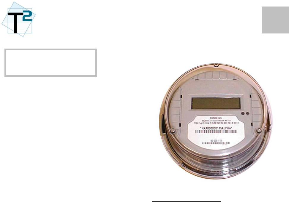
The M2e radio is a modular AMR
and datalogging device designed for
embedding with Landis & Gyr
FOCUS line electronic meters.
Simple
The M2e operates in an unlicensed
mode in the 900-Mhz range which
requires no utility regulation. The
radio is easily configured and
interfaced via the G2 Mobile System.
Powerful
In addition to reliable meter reading,
the M2e also provides powerful
datalogging, consumption profiling
and usage flags. The M2e transmits
basic meter usage data and
customer service information
through the RF signal.
Basic Specifications
Transmission: One-Way
Config/Datalogging: Two-Way
(unregulated)
Regulatory: FCC 15.247
Approval: Modular
Temperature: -40F to 158F
(-40C to +70C)
Housing: Embedded within
L&G Electric Meter
Power: 5V supply from
L&G electric meter
Battery: Coin Cell for Last
Gasp during
outage only
OVERVIEW
2
1
M2e Housing
The M2 is housed within a Landis &
Gyr FOCUS line electric meter.
The M2e radio is pre-installed at the
factory and should not be removed
or tampered with.
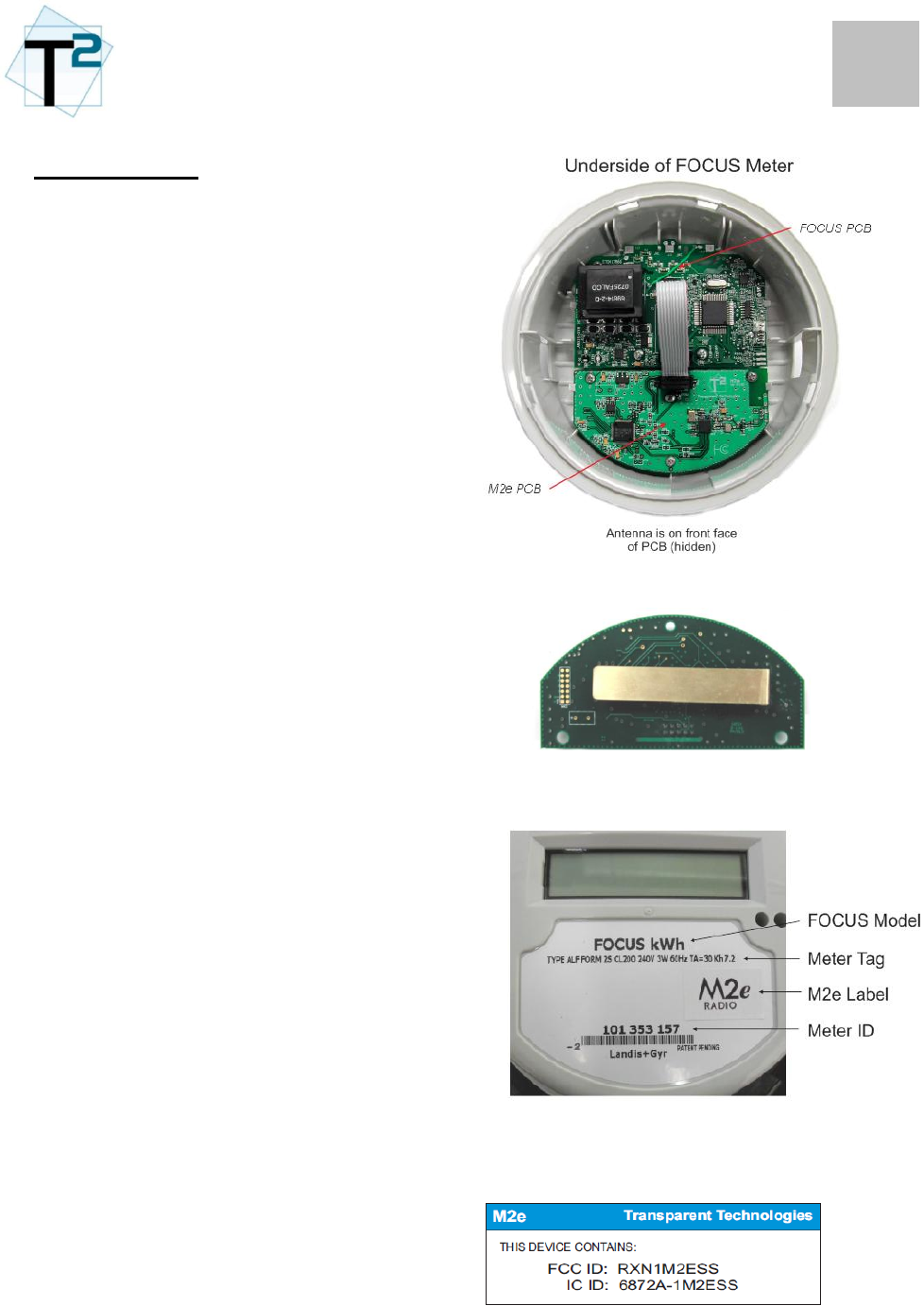
The diagram to the right shows the
embedded M2e board installed in a
L&G FOCUS meter.
The antenna is on the front side of
the M2e PCB as shown in the lower
picture.
The FOCUS label will show the
meter model, the meter tag
information, an M2e label and the
meter ID.
The M2e radio FCC Label will be
placed on the side of the FOCUS
housing.
M2e Antenna
FOCUS Label

1
2
Electric Meter Installation
Refer to Landis & Gyr
documentation and local electrical
code for installation requirements of
the FOCUS meter. All installations
should be performed by qualified
electrical professionals.
M2e Installation
The M2e is designed for embedding
within a Landis & Gyr electric meter
only.
For safety and quality assurances,
the installation of the M2e radio
PCB must be performed at the T2
factory.
Removal or alternation of the M2e
PCB within the FOCUS meter will
result in a void of warranty.
Notice:
Per FCC and Industry Canada
regulations, the Landis & Gyr meter
with the M2e radio should never be
installed within 8 inches (20cm ) of
typical people locations.
Radio Orientation
The FOCUS meter is intended to be
installed vertically (such that the front
panel LCD is visible). In this orientation,
the M2e antenna is positioned in the
optimum way and should perform well.
INSTALLATION

1
3
FOCUS Electric Meter
Refer to Landis & Gyr documentation for operational information on the FOCUS electric
meters.
Note: Certain functions of the M2e radio are only available on certain FOCUS models. This
section will identify these functions.
M2e AMR Operations
The M2e radio is a full transceiver. Its standard mode of operation is to transmit its standard
data packet on a regular interval. This standard data packet contains the following
information:
Meter ID
Meter Read (kWh+)
Data Flags
Meter Read (kWh-)
The M2e radio standard transmit interval is 3 seconds.
After each transmission, the M2e radio turns on its receiver and listens for any command
coming from the mobile system transceiver. These commands can be for configuration or
datalogging. This is the mode of handshaking for 2-way communications.
M2e Datalogging
Via the G2 Mobile software, the user can request the following datalogs:
kWh Consumption (60 min intervals)
Instantaneous Voltage (1 min intervals)
Instantaneous Power (1 min intervals)
The data is stored in CSV files on the G2 Mobile laptop for viewing and analysis.
M2e Configuration
Via the G2 Mobile software, the user can perform data verifications and re-configuration of
the M2e settings.
The Landis & Gyr FOCUS meters also have an infrared port which allows a “passthrough”
mode. Utilizing the L&G IR module, the user can perform a configuration of the radio.
OPERATION
2
3
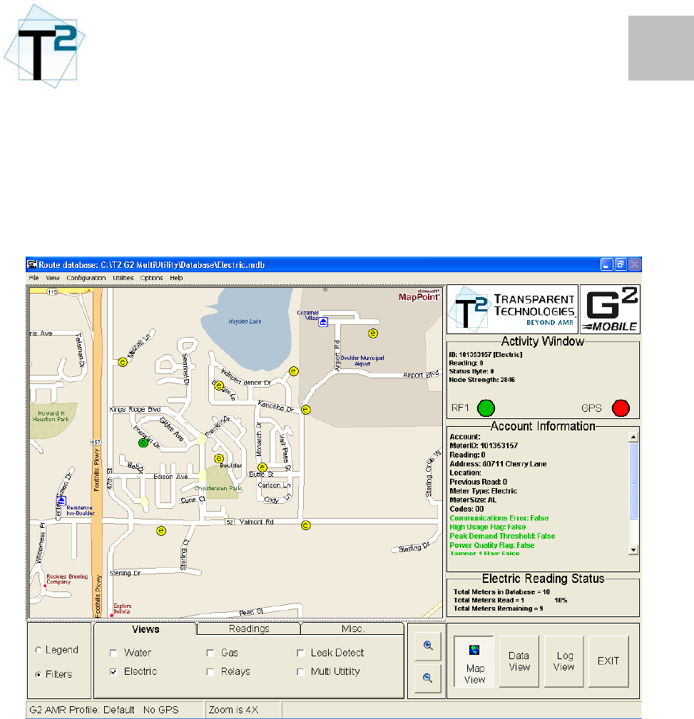
AMR and Datalogging
For standard meter reading and datalogging applications, the user will utilize the G2 Mobile
Multi-Utility software. G2 Mobile is a map-based, GPS enabled reading software. The G2
Mobile software also provides the ability to download datalogs from any T2 radio.
Refer to the G2 Mobile Multi-Utility manual for complete software operational instructions.
3
3
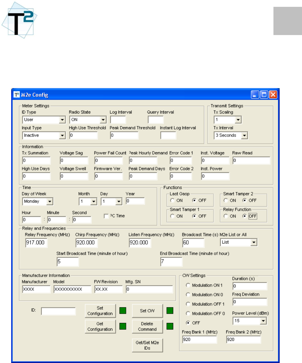
M2e Configuration
T2 will provide a configuration software for the RF configuration of M2e radios. The
software screen for configuration will appear as shown:

4
3
The software will have a GET Data button, which will initiate the communication with the
M2e board. The command will retrieve the entire M2e data packet and populate the data
shown.
The software will also have a SET Data button, which will initiate an updated data packet
being sent to the M2e board.
The available settings on the M2e radio (default settings are shown in bold)
Meter Settings Selections
ID Type: User / Meter
Meter Type: L&G FOCUS kWh
Tx Summation: kWh+, kWh-, Net, Added
Transmit Settings Selections
Transmit Interval 2, 3, 4, 5, 6, 7, 8, 9, 10
Transmit Scaling N/A
Data/Log Settings Selections
Log/Query Interval 1, 2, 5, 10, 15, 20, 30, 60
Peak Demand Days 0 (off) to 31
Peak Demand Threshold Selectable kWh
High Usage Days 0 (off) to 31
High Usage Threshold Selectable kWh
Voltage Sag% 0 to 100% (10%)
Voltage Swell% 0 to 100% (10%)
5
3
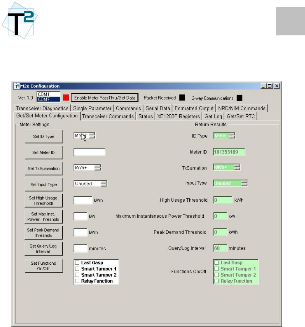
IR Configuration
T2 will provide a configuration software for the IR configuration of M2e radios. The software
screen for configuration will appear as shown:
ComPort: The user will need to select the comport that is assigned to the L&G IR
module. Once the valid port is selected, the indicator light will turn green.
Enable Meter Pass Through / Get Data: This button will send the proper command to the
FOCUS meter to enable the pass-through and then forward the M2e
command.
The settings are the same as described in the RF section.

1
5
To be completed
TROUBLESHOOTING

1
A
FCC Information
Information to user. - The users manual or
instruction manual for an intentional or
unintentional radiator shall caution the user
that changes or modifications not expressly
approved by the party responsible for
compliance could void the user's authority
to operate the equipment.
Special accessories.
(a) Equipment marketed to a consumer
must be capable of complying with the
necessary regulations in the configuration
in which the equipment is marketed.
Where special accessories, such as shielded
cables and/or special connectors, are
required to enable an unintentional or
intentional radiator to comply with the
emission limits in this part, the equipment
must be marketed with, i.e., shipped and
sold with, those special accessories.
However, in lieu of shipping or packaging
the special accessories with the
unintentional or intentional radiator, the
responsible party may employ other
methods of ensuring that the special
accessories are provided to the consumer,
without additional charge, at the time of
purchase. Information detailing any
alternative method used to supply the
special accessories shall be included in the
application for a grant of equipment
authorization or retained in the verification
records, as appropriate.
The party responsible for the equipment, as
detailed in §2.909 of this chapter, shall ensure
that these special accessories are provided with
the equipment. The instruction manual for such
devices shall include appropriate instructions on
the first page of the text concerned with the
installation of the device that these special
accessories must be used with the device. It is
the responsibility of the user to use the needed
special accessories supplied with the equipment.
(b) If a device requiring special accessories is
installed by or under the supervision of the
party marketing the device, it is the
responsibility of that party to install the
equipment using the special accessories. For
equipment requiring professional installation, it
is not necessary for the responsible party to
market the special accessories with the
equipment. However, the need to use the
special accessories must be detailed in the
instruction manual, and it is the responsibility
of the installer to provide and to install the
required accessories.
(c) Accessory items that can be readily
obtained from multiple retail outlets are not
considered to be special accessories and are not
required to be marketed with the equipment.
The manual included with the equipment must
specify what additional components or
accessories are required to be used in order to
ensure compliance with this part, and it is the
responsibility of the user to provide and use
those components and accessories.
(d) The resulting system, including any
accessories or components marketed with the
equipment, must comply with the regulations.
APPENDIX – FCC / IC INFORMATION

2
A
FCC Definitions
Class A digital device. A digital device
that is marketed for use in a commercial,
industrial or business environment,
exclusive of a device which is marketed for
use by the general public or is intended to
be used in the home.
Class B digital device. A digital device
that is marketed for use in a residential
environment notwithstanding use in
commercial, business and industrial
environments. Examples of such devices
include, but are not limited to, personal
computers, calculators, and similar
electronic devices that are marketed for use
by the general public.
NOTE: The responsible party may also
qualify a device intended to be marketed
in a commercial, business or industrial
environment as a Class B device, and in
fact is encouraged to do so, provided the
device complies with the technical
specifications for a Class B digital
device. In the event that a particular type
of device has been found to repeatedly
cause harmful interference to radio
communications, the Commission may
classify such a digital device as a Class B
digital device, regardless of its intended
use.
For a Class A digital device or peripheral,
the instructions furnished the user shall
include the following or similar statement,
placed in a prominent location in the text of
the manual:
This equipment has been tested and found
to comply with the limits for a Class A
digital device, pursuant to Part 15 of the
FCC Rules. These limits are designed to
provide reasonable protection against
harmful interference when the equipment
is operated in a commercial environment.
This equipment generates, uses, and can
radiate radio frequency energy and, if not
installed and used in accordance with the
instruction manual, may cause harmful
interference to radio communications.
Operation of this equipment in a residential
area is likely to cause harmful interference in
which case the user will be required to correct
the interference at his own expense.
For a Class B digital device or peripheral, the
instructions furnished the user shall include the
following or similar statement, placed in a
prominent location in the text of the manual:
This equipment has been tested and found to
comply with the limits for a Class B digital
device, pursuant to Part 15 of the FCC Rules.
These limits are designed to provide
reasonable protection against harmful
interference in a residential installation. This
equipment generates, uses and can radiate
radio frequency energy and, if not installed
and used in accordance with the instructions,
may cause harmful interference to radio
communications. However, there is no
guarantee that interference will not occur in a
particular installation. If this equipment does
cause harmful interference to radio or
television reception, which can be determined
by turning the equipment off and on, the user
is encouraged to try to correct the interference
by one or more of the following measures:
- Reorient or relocate the receiving antenna.
- Increase the separation between the
equipment and receiver.
- Connect the equipment into an outlet on a
circuit different from that to which the
receiver is connected.
- Consult the dealer or an experienced
radio/TV technician for help.
The provisions of paragraphs (a) and (b) of this
section do not apply to digital devices exempted
from the technical standards under the
provisions of §15.103.
3
A
FCC / IC Declarations
The M2 Utility Radio Tranceiver is an
approved intentional radiator device under
FCC 15.247 and Industry Canada under
RSS-210.
THIS DEVICE COMPLIES WITH PART
15 OF THE FCC RULES AND TO
INDUSTRY CANADA RSS120.
OPERATION IS SUBJECT TO THE
FOLLOWING TWO CONDITIONS:
(1) THIS DEVICE MAY NOT CAUSE
HARMFUL INTERFERENCE, AND
(2) THIS DEVICE MUST ACCEPT ANY
INTERFERENCE RECEIVED,
INCLUDING INTERFERENCE THAT
MAY CAUSE UNDESIRED
OPERATION.
The M2 Radio is a self-contained unit and
access to its circuitry by an end user, other
than replacement of the battery, is not
intended. Changes or modifications not
expressly approved by Transparent
Technologies or use of the radio other than
the purposes described herein voids the
user's authority to operate the equipment.
Industry Canada product labeling.
“IC” before the equipment certification
number only signifies that the Industry
Canada technical specifications were met.