Tranwo Technology ACS-5820R 5.8Ghz Cable sender User Manual cable sender manual 0601103
Tranwo Technology Corp 5.8Ghz Cable sender cable sender manual 0601103
User manual
QUICK INSTALL GUIDE
Model:
5.8 GHz Cable Sender
• software, warranty card, and user manuals.
1. Package Content ………………………………
2. Panel Control and Function …...……………………………
3. Setup Guide ………………….……………
4. Orient Transmitter/Receiver for optimal performance…….….
5. Specification……………………………………………………
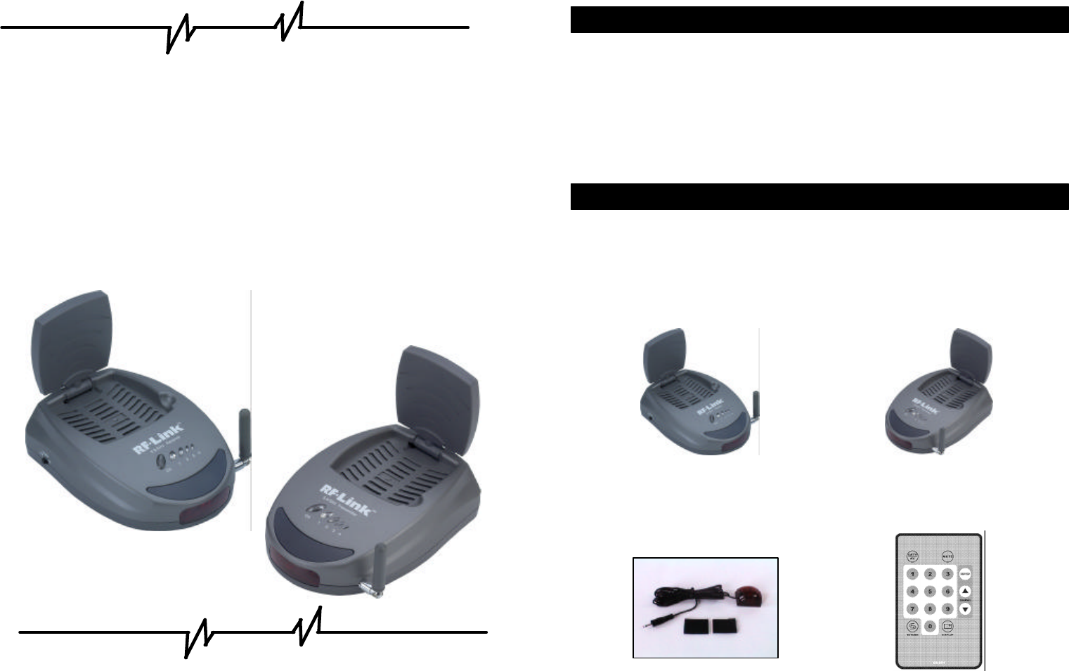
Check to make sure that all units shown as below are enclosed. If something
missed, please contact your dealer.
1. 5.8GHz Transmitter * 1 2. 5.8GHz Receiver * 1
UHF: 433.92MHz (USA Standard)
3. IR Mouse * 1 / fasten strips * 2 4.IR Remote Controller * 1
Contents
1. Package Content
5. Accessories
(1) Power Adapters (120V) * 2 (2) RCA Cable * 2
(3) Co-axial T-plug (4) Co-axial cable
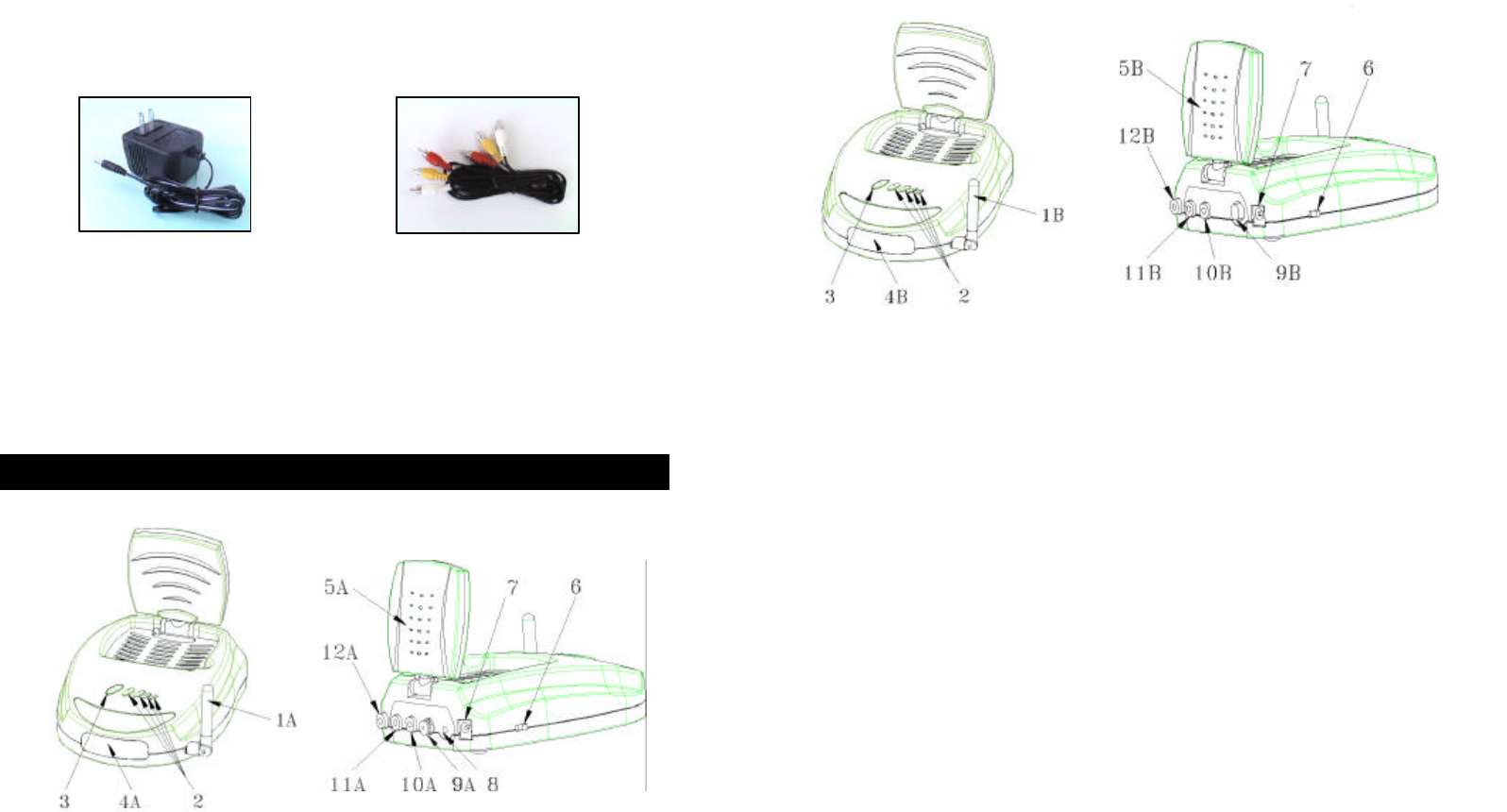
5.8GHz Transmitter
5.8GHz Receiver
1A – UHF antenna receives remote control signal.
1B – UHF antenna sends remote control signal.
2 – Indicator lights show the channel it configured as.
3 – Channel selection button to find optimal reception, the transmitter and receiver must to be
Configured as the same channel.
4A – Remote control window sends IR rays, to remotely control the source AV equipment.
4B – Remote control window receives IR rays from remote controller.
5A – Directional 5.8GHz A/V antenna sends A/V signal from source equipment.
5B – Directional 5.8GHz A/V antenna receives audio and video signal.
6 – Power on/off switch.
7 – DC power input, connect to power supply. (9V).
8 – IR Mouse output, to remotely control source AV equipment.
9A –-CABLE IN (75?), CATV Cable in.
9B – No available (To TV)
10A–Video Jack, (yellow), input from source AV equipment.
10B–Video Jack, (yellow), output to TV.
11A–Audio Jack, Right (red), input from source AV equipment.
11B–Audio Jack, Right (red), output to TV.
2. Panel Control and Function
12A–Audio Jack, Left (white), input from source AV equipment.
12B–Audio Jack, Left (white), output to TV.
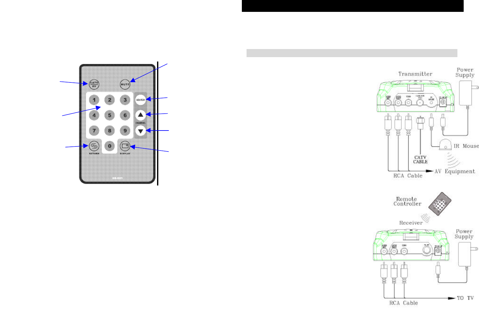
IR Remote Controller
1 CATV/AV : For switching Video signal and cable TV channels
2 CH + / CH - : For paging up and down through the cable TV Channels
3 SEARCH : Automatic search tuning for cable TV and memorize it
4 MUTE : Silent
5 DISPLAY : Displays the selected mode : Channel number or AV
6 RETURN : Switching back to the channel last selected
7 NUMBER BUTTONS : TV channel selection
3.1 To enjoy a life of wireless video and audio, just connect the transmitter to any
A/V source you like and CATV cable, and connect the receiver to a TV,
monitor or speaker in another location.
□ Transmitter
□ Receiver
CH +
CH -
CATV/AV
NUMBER BUTTONS
SEARCH
MUTE
DIAPLAY
RETURN
NOTE: Make sure the ON/OFF switch is in the
「OFF」position before connection
3. Setup Guide
1.
Connect one end of the RCA cable to the
audio and video jack
s, and connect the other
end to a source device via its “AV output”.
2. Connect the CATV cable to the Cable IN jack.
3.
Connect the DC plug of the adapter to the DC
jack, and connect the power supply to an
outlet.
4.
Fix IR mouse next to or in front of IR sensor
of
source device, or alternatively have
transmitter
facing directly toward the source
1.
Connect one end of the RCA cable to the
audio and video jacks and connect the
other end to a TV (or monitor, speakers)
via its “AV input”.
2.
Connect the DC plug of the adapter to the
DC jack, and connect the power supply to
an outlet.
3. Keep the IR window oriented toward
front when using your
source device
remote controller.
3.2 After setup your transmitter and receiver,the first time to enjoy
CATV on Cable Sender,It needs to scan and find the available
channels ,please follow procedure below :
l The first step : turn on your TV set and Switch to AV IN.
l The step 2 : power on the cable sender (Transmitter and Receiver ) and
select the same channel you like .
l The step 3 : push “CATV/AV “ button on IR Remote Controller to
switch Cable Sender to CATV mode.
l The step 4 : Programming the cable tuner using “search” button on IR
Remote Controller to automatic scan and find the available channels ,
and memorize it.
l The step 5 : Using CH+/CH- button on IR Remote Controller for
paging up/down channel , using “NUMBER” button to select TV
channel you like.
For optimal performance, both the audio/video and remote control antennas should
be carefully oriented as described below. For maximum transmitting range, try to
minimize obstacles (e.g. your TV or other electronics, large furniture) where
between the transmitter and receiver.
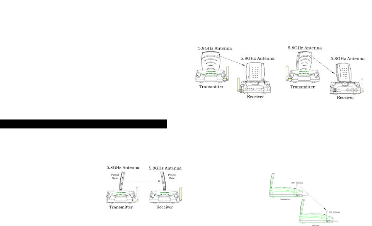
Orients the 5.8GHz A/V Antennas
Orients the UHF Antennas
In order to obtain optimal performance of the remote control extender, the remote
control antennas should also be oriented at a right angle to an imaginary line
drawn between the transmitter and receiver. If your remote control extender is not
working satisfactorily, rotate the remote control antenna on either the transmitter
or receiver 90 degrees so that it is still perpendicular to the path between the units.
(See Fig-4)
If you notice improved performance, keep this orientation. Rotating the antenna on
both units should have no effect.
4. Orient Transmitter/Receiver for optimal performance
The system delivers high-
quality audio and
vide
o by using directional antennas, which must
be oriented in the best ways. The antennas are
designed to be able to vertically and horizontally
pivot and rotate in almost any direction.
In most situations, the flat-
pitted face of the antennas on both the transmitter and
receiver should be facing one another and perpendicular (at a right angle) to an
Fig-2
Fig-3
Fig-1
imaginary line drawn between the two units. Three examples are shown as Fig-
1,
Fig-2 and Fig-
3. Since all homes are different, for optimal reception, additional
slight pivots or rotations may be necessary.
If the transmitter and receiver are
less than 10 feet apart, suggest that the antennas are lying on their casings since
the distance is so short.
Fig-4
5.1 Transmitter
5.1.1 General specification
Input Voltage DC 9V ± 0.5V
Current Consumption < 350mA
Antenna Type Patch (34 * 34mm)
Operation temperature & humidity
0℃ ~ +50℃ less than
85%
Storage temperature & humidity -20℃ ~ +70℃ less
than 90%
5.1.2 Electrical specification
RF
Output power @ connector +0 dBm MIN
Modulation Type FM
RF Deviation(FM) 6.4MHz peak to peak
CH1
5745MHz
CH2
5765MHz
CH3
5785MHz
Channel Frequency
CH4
5805MHz
Channel Selection Tact Switch
Frequency Stability ±250KHz
Output Flatness 0 ~ +3dB
Video
Input Level 1V peak to peak
Impedance 75 ohms
Pre-Emphasis NTSC
D.G. < ±8%
D.P. < ±8%
Audio
Input Level 1.4V peak to peak
Impedance 600 ohms
Frequency Response 30Hz ~ 12KHz
Audio Carrier Frequency(L)
6.0MHz ±25KHz
Audio Carrier Frequency(R)
6.5MHz ±25KHz
Audio Distortion 3% max. THD
AM Rejection 40dB min.
5.2 Receiver
5.2.1 General specification
Input Voltage DC 9V ±0.5V
Current Consumption < 400mA
Antenna Type Patch (34 * 34mm)
Operation temperature & humidity
0℃ ~ +50℃ less than 85%
Storage temperature & humidity -20℃ ~ +70℃ less than 90%
5.2.2 Electrical specification
RF
Input Frequency Range 5745 ~ 5805MHz
Input Level @ connector -25 ~ -80dBm
IF Frequency 479.5MHz
IF Bandwidth 18MHz
Gain Flatness 3dB max.
Noise Figure 2dB Typical
Input Return Loss 7dB Typical
LO. Drift ±250KHz
5. Specification
LO. Leakage -50dBm max.
Image Rejection 40dB
Video
Output Level 1V ±0.15Vp-p Load.
Impedance 75 ohms
De-Emphasis NTSC
D.G. < ±8%
D.P. < ±8%
Video S/N Ratio 38dB min.
Audio
Output Level 1Vp-p ±0.2
Impedance 600 ohms
Frequency Response 30Hz ~ 12KHz
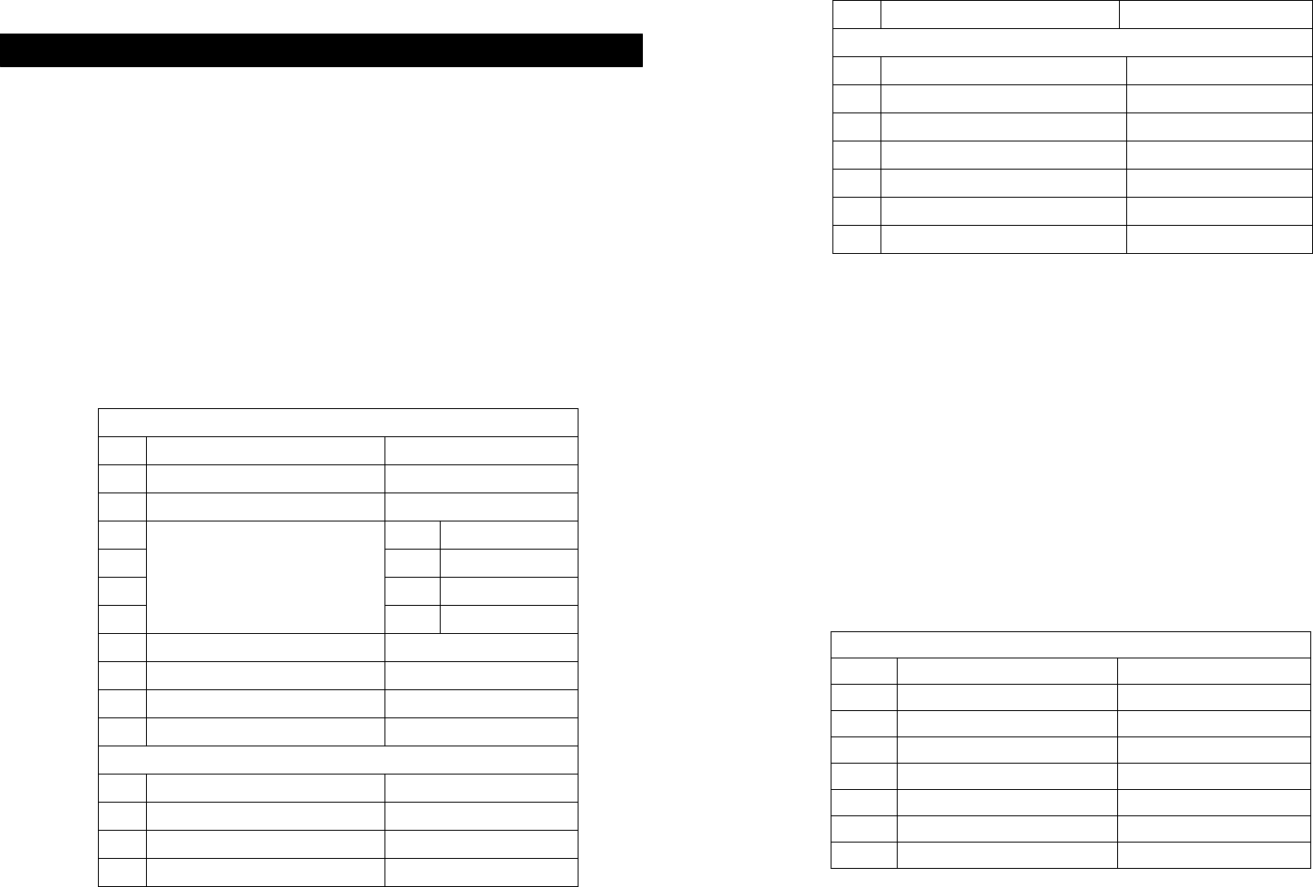
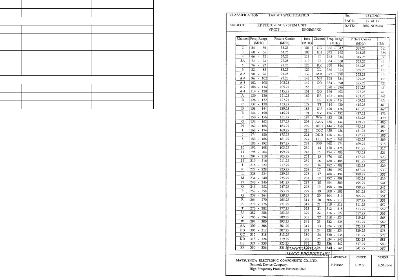
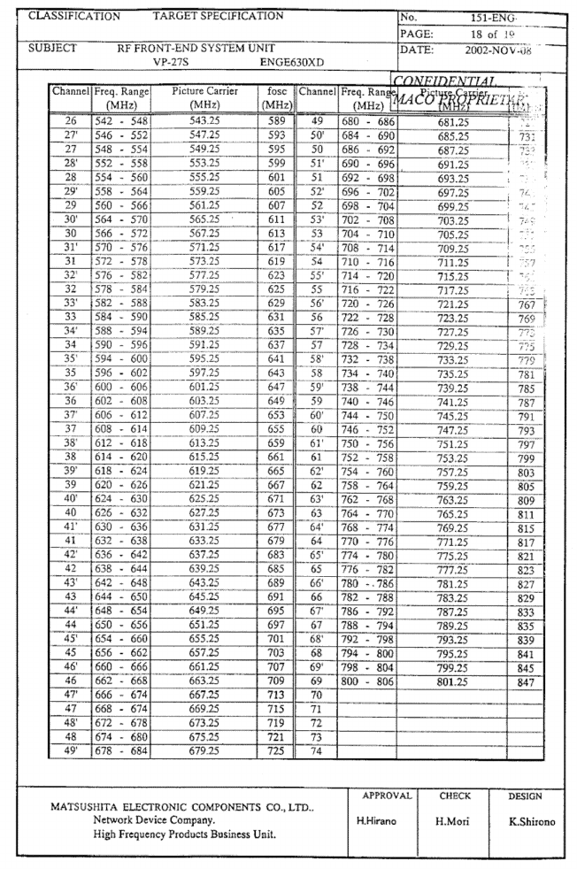
5.3 TV Tuner : OSD ENGE630XD(VP-27S)
5.3.1 Channel
(VHF): Band I ch. 2 à I (fp=55.25 à 169.25MHz)
Band II ch. 7 à EEE (fp=175.25 à 463.25MHz)
(UHF): Band III ch.FFF à 69 (fp= 469.25 à 801.25MHz)
5.3.2 Receiver System : NTSC
5.3.3 Input System : U/V terminals 75 ohm Unbalance
5.3.4 Channel Table
Notice : The changes or modifications not expressly approved by the
party responsible for compliance could void the user’s authority to
operate the equipment.
To comply with the FCC RF exposure compliance requirements, no
change to the antenna or the device is permitted. Any change to the
antenna or the device could result in the device exceeding the RF
exposure requirements and void user’s authority to operate the
device.
The equipment has been tested and found to comply with the limits for a
ClassB Digital Device, pursuant to part 15 of the FCC Rules. These
limits are designed to provide reasonable protection against harmful
interference in a residential installation. This equipment generates,
uses and can radiate radio frequency
energy and, if not installed and used in accordance with the instruction,
may cause harmful interference to radio communication.