Tranwo Technology GIGAAIR-30T 2.4GHz Transmitter User Manual 4110mal
Tranwo Technology Corp 2.4GHz Transmitter 4110mal
UserManual.wiki
>
Tranwo Technology
>
GIGAAIR-30T User Manual
>
users manual
Contents
1.
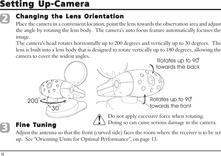
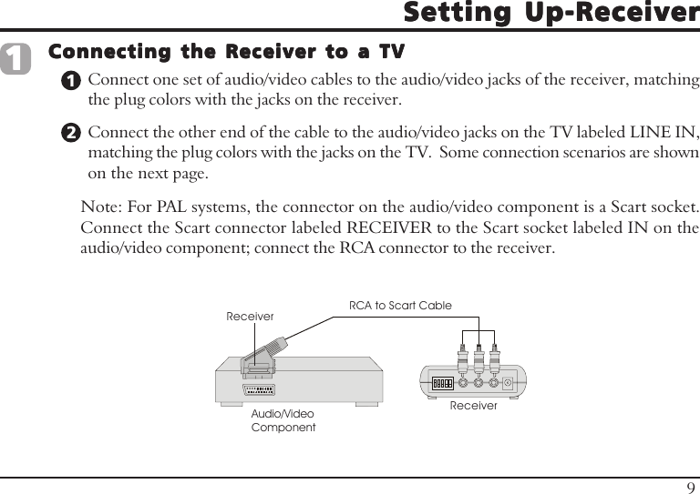
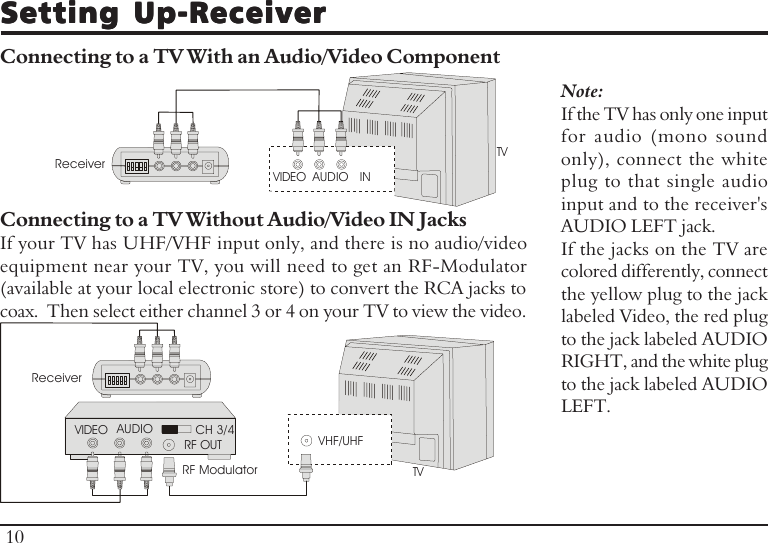
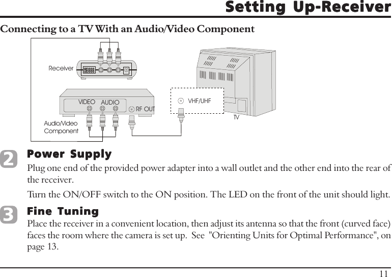
User Manual
2.
users manual
users manual
Navigation menu
Upload a User Manual
Namespaces
Wiki Guide
HTML
PDF
Info
Views
User Manual
Discussion / Help
Navigation