Tranzeo Wireless Technologies PVE35XBY WIRELESS NETWORKING DEVICE User Manual TR WMX 3 5 User s Manual
Tranzeo Wireless Technologies, Inc WIRELESS NETWORKING DEVICE TR WMX 3 5 User s Manual
USERS MANUAL

TR
-
WMX
-
3.5 WiMAX Subscriber Unit
User’s Guide
Document Number TRONNN
-
A2
May 2008
FastFind Links
Preface
Table of Contents
Basic Installation
Advanced Configuration

TR-WMX-3.5 Subscriber Unit User's Guide
ii
© 2008 Tranzeo Wireless Technologies Inc. ALL RIGHTS RESERVED
No part of this publication may be reproduced or transmitted in any form or by any
electronic or mechanical means, including photocopying and recording, or stored in a
database or retrieval system for any purpose, without the express written permission of
Tranzeo Wireless Technologies Inc.
Tranzeo Wireless Technologies Inc. reserves the right to make changes to this document
at any time without notice and assumes no responsibility for its use. Tranzeo Wireless
Technologies Inc. products or services can only be ordered under the terms and
conditions of Tranzeo Wireless Technologies Inc.’s applicable agreements, including
license agreements. All of the features described in this document may not be currently
available. Refer to the most recent product announcement or contact Tranzeo Wireless
Technologies Inc. for information about feature and product availability.
This document contains the most current information available at the time of
publication. When new and/or revised information becomes available, this document
may be updated and made available to all registered users.
Trademarks
Tranzeo, the Tranzeo logo, and TR-WMX-3.5 are trademarks of Tranzeo Wireless
Technologies Inc.
All other brand or product names are or may be trademarks or service marks of and are
used to identify products or services of their respective owners.
Product Version
This document revision applies to TR-WMX-3.5 Indoor and Outdoor WiMAX Subscriber
Units 1.11xx and higher running firmware version 3.0 and higher.
Document Revision Level
Revision Date Description
A1 April 2008 Initial Release
A2 May 2008 Revision 2, supersedes and replaces A1
Changes in this Revision
Includes information about the indoor unit.
TR-WMX-3.5 Subscriber Unit User's Guide
iii
Preface
Welcome to the Tranzeo TR-WMX-3.5 WiMAX Subscriber Unit User’s Guide. The TR-WMX-
3.5 WiMAX Subscriber Unit supports point-to-multipoint communication with an IEEE
802.16-2004-compliant WiMAX base station. This guide contains all the information you
need to install and configure the TR-WMX-3.5 WiMAX Subscriber Unit.
Purpose and Audience
This guide is designed for anyone who installs, configures, deploys, or prepares a site for
the TR-WMX-3.5 WiMAX Subscriber Unit. This guide is intended for the following
audiences:
Customers with a technical knowledge of and experience with networks and the
Internet.
Network administrators who install, configure, and manage Tranzeo TR-WMX-3.5
WiMAX Subscriber Units.
Network administrators who install, configure, and manage other Tranzeo or similar
products, but are unfamiliar with the Tranzeo TR-WMX-3.5 WiMAX Subscriber Unit.
Models and Configurations
The TR-WMX-3.5 WiMAX Subscriber Unit is available in a variety of models and
configurations. The following table lists some of the models available.
TR-WMX-3.5 Models and Configurations
Model Number Configuration and Description
TR-WMX-3.5-14 3.5 GHz subscriber unit with integrated 14dBi antenna
TR-WMX-3.5-17 3.5 GHz subscriber unit with integrated 17dBi antenna
TR-WMX-3.5-20 3.5 GHz subscriber unit with integrated 20 dBi antenna
TR-WMX-3.5-N 3.5 GHz subscriber unit with N-type connector
In this document, the term “TR-WMX-3.5” is used to refer collectively to the
family of TR-WMX-3.5 indoor and outdoor WiMAX Subscriber Unit products. If
information in this document pertains to certain models, the term “indoor” or
“outdoor” will be used along with the particular model number.

Preface
TR-WMX-3.5 Subscriber Unit User's Guide
iv
TR-WMX-3.5 Features
The TR-WMX-3.5 is designed for quick installation. The following list summarizes the key
features of the TR-WMX-3.5.
Complies with IEEE 802.16-2004 for communication with WiMAX base stations that
support this standard.
Supports multiple duplex modes and channel bandwidths.
Power-over-Ethernet (PoE) capabilities allow data and power to be supplied to the unit
using a single Ethernet cable.
Includes an external or embedded antenna.
External signal strength LEDs allow the antenna to be aligned for optimal received signal
strength from the base station, without having to use a computer to log in to the unit.
Summary of Chapters
This guide contains the following chapters.
Chapter 1, Basic Installation includes instructions for getting the TR-WMX-3.5 WiMAX
Subscriber Unit up and running as quickly as possible.
Chapter 2, Advanced Configuration describes how to perform advanced configuration
activities using the Web-based Configurator.
Chapter 3, Viewing Status Information describes how to use the Configurator to
view/change status information about TR-WMX-3.5.
Chapter 4, Configuring Administrative Settings describes how to use the Configurator
to view change the device name and location; enable or disable Web, SSH, and Telnet
access to the TR-WMX-3.5; enable or disable the TR-WMX-3.5 status LEDs; and change
the user name and password for logging in to the Configurator.
Appendix A, Factory Default Configuration Settings lists the factory default
configuration settings for the TR-WMX-3.5.
Appendix B, Upgrading Firmware describes how to upgrade the TR-WMX-3.5 firmware.
Release Notes
The Release Notes provided with your TR-WMX-3.5 contain information that may not
have been available when this User’s Guide was written. We recommend you read the
Release Notes before installing and configuring your TR-WMX-3.5.
Preface
TR-WMX-3.5 Subscriber Unit User's Guide
v
Document Conventions
This document uses the following conventions to draw your attention to certain
information.
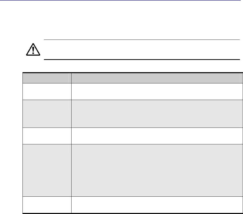
Safety and Warnings
This document also uses the following symbols to draw your attention to certain
information.
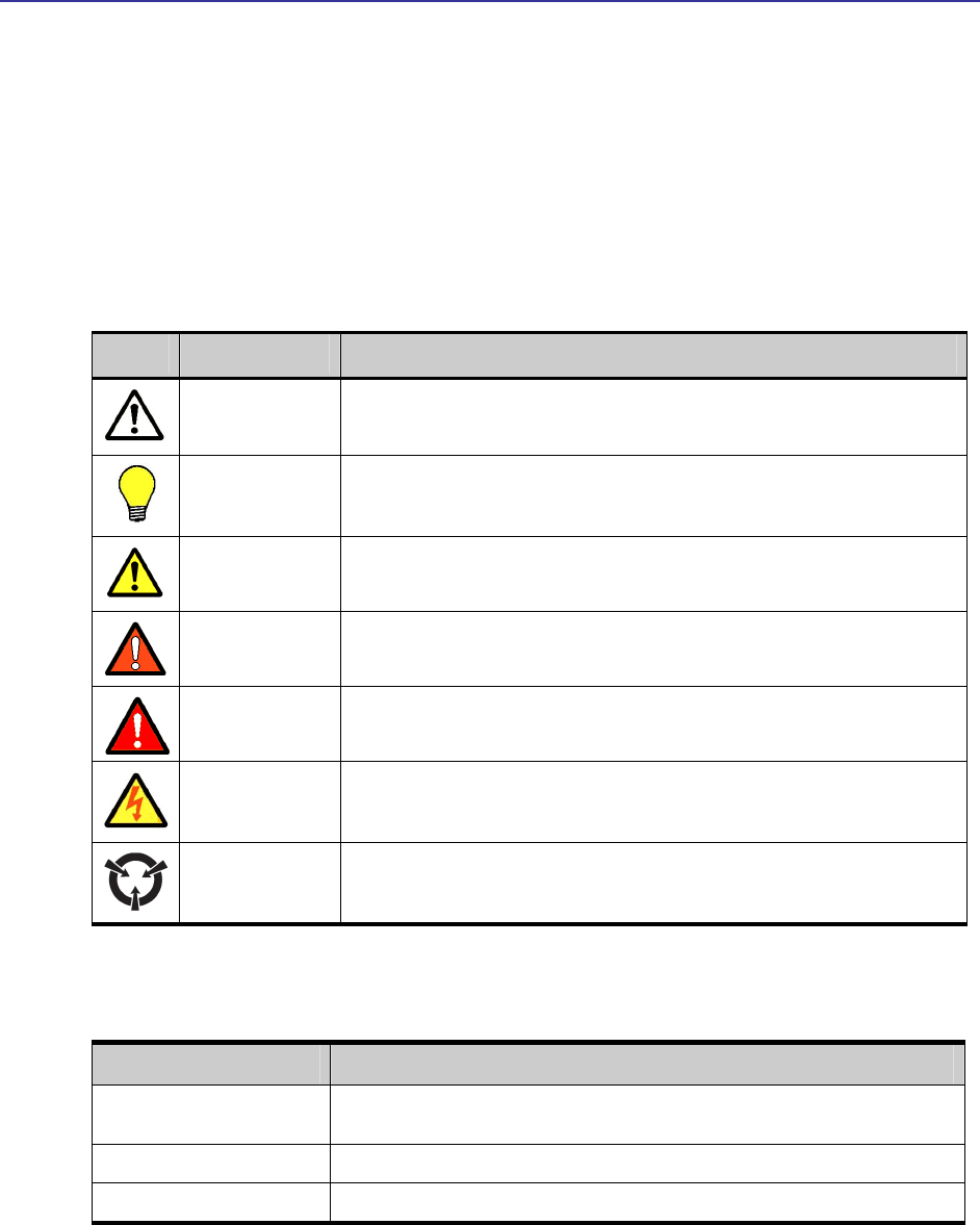
Icon Meaning Description
Note Notes emphasize or supplement important points of the main text.
Tip Tips provide helpful information, guidelines, or suggestions.
Caution Cautions indicate that failure to take a specified action could result in damage to the
software or hardware.
WARNING Warnings indicate that failure to take a specified action could result in loss of
communications or serious damage to hardware.
DANGER Danger warns users of possible injury or death if instructions are not followed.
ELECTRIC SHOCK
HAZARD
This symbol warns users of electric shock hazard. Failure to take appropriate
precautions such as not opening or touching hazardous areas of the equipment could
result in injury or death.
Electrostatic
Sensitive
The ESD symbol warns users that the equipment is sensitive to electrostatic discharge
(ESD) and could be damaged if users do not take appropriate precautions such as using
a grounded wrist strap when touching or handling the equipment.
Typographic Conventions
The following typographic conventions are used in this document.
Convention Description
Bold Indicates text on a window, other than the window title, including menus, menu options,
buttons, fields, and labels.
Italic Indicates a variable, which is a placeholder for actual text provided by the user or system.
screen font Indicates text that is displayed on screen or entered by the user.

Preface
TR-WMX-3.5 Subscriber Unit User's Guide
vi
Contact Information
For more information about the TR-WMX-3.5 or other products from Tranzeo Wireless
Technologies Inc., please contact us using any of the following methods:
Web site: Our Web site contains valuable information about our products. We encourage
you to visit us at http://www.tranzeo.com.
Sales: Our Sales Department can be reached by phone or email:
– Phone: +1 866 872-6936
– Email: sales@tranzeo.com
Fax calls: Requests for information can be sent to our 24-hour fax number:
+1 604 460 6005.
Technical support: Technical support, the customer-satisfaction arm of Tranzeo
Wireless Technologies Inc., is available by phone, live chat, email, and fax. For more
information, see Appendix C.
TR-WMX-3.5 Subscriber Unit User's Guide
vii
Contents
1 BASIC INSTALLATION ..................................................................................................................................1
1.1 SAMPLE CONFIGURATION ...............................................................................................................................2
1.2 UNPACKING ...................................................................................................................................................3
1.3 USER-SUPPLIED ITEMS ...................................................................................................................................3
1.4 INSTALLING THE TR-WMX-3.5......................................................................................................................4
1.4.1 Installing the Outdoor Unit.....................................................................................................................4
1.4.2 Installing the Indoor Unit........................................................................................................................6
1.4.3 Installation Best Practices ......................................................................................................................7
1.5 CONFIGURING THE TR-WMX-3.5...................................................................................................................8
1.5.1 Logging in to the Configurator................................................................................................................8
1.5.2 Specifying Wireless Settings..................................................................................................................10
1.5.3 Specifying Network Setup Settings.........................................................................................................13
1.6 MONITORING TR-WMX-3.5 STATUS ............................................................................................................15
1.6.1 Viewing Status Information...................................................................................................................15
1.6.2 Status LEDS .........................................................................................................................................16
2 ADVANCED CONFIGURATION ..................................................................................................................17
2.1 UNDERSTANDING THE PAGES IN THE CONFIGURATOR ....................................................................................18
2.2 ENTERING WIMAX SETUP SETTINGS............................................................................................................20
2.2.1 Entering Wireless Settings ....................................................................................................................20
2.2.2 Setting Security Settings........................................................................................................................24
2.3 ENTERING NETWORK SETUP SETTINGS .........................................................................................................25
2.3.1 Entering TCP/IP Settings......................................................................................................................25
2.3.2 VLAN Settings ......................................................................................................................................27
3 VIEWING STATUS INFORMATION ...........................................................................................................31
3.1 INFORMATION PAGE .....................................................................................................................................32
3.2 WIRELESS INFORMATION PAGE.....................................................................................................................34
3.3 SYSTEM INFORMATION PAGE........................................................................................................................36
3.4 STATISTICS INFORMATION PAGE ...................................................................................................................38
3.5 ARP INFORMATION PAGE.............................................................................................................................40
3.6 SYSTEM LOG................................................................................................................................................41
4 CONFIGURING ADMINISTRATIVE SETTINGS .....................................................................................43
4.1 DISPLAYING THE ADMINISTRATIVE SETTINGS PAGE ......................................................................................44
4.2 RETURNING TO FACTORY DEFAULT SETTINGS...............................................................................................44

Table of Contents
TR-WMX-3.5 Subscriber Unit User's Guide
viii
4.3 REBOOTING THE TR-WMX-3.5 UNIT ............................................................................................................45
4.4 CHANGING DEVICE CONFIGURATION SETTINGS.............................................................................................45
4.4.1 Changing the Device Name and Location..............................................................................................45
4.4.2 Enabling or Disabling Web, SSH, and Telnet Access .............................................................................46
4.4.3 Enabling or Disabling the Status LEDs .................................................................................................46
4.4.4 Changing Log In Settings......................................................................................................................47
A FACTORY DEFAULT CONFIGURATION SETTINGS.........................................................................49
A.1 DEFAULT WIRELESS SETTINGS.....................................................................................................................49
A.2 DEFAULT SECURITY SETTINGS .....................................................................................................................50
A.3 DEFAULT TCP/IP SETTINGS.........................................................................................................................50
A.4 DEFAULT VLAN SETTINGS..........................................................................................................................50
A.5 DEFAULT ADMINISTRATIVE SETTINGS..........................................................................................................50
B UPGRADING FIRMWARE ........................................................................................................................51
C TECHNICAL SUPPORT.............................................................................................................................53
C.1 TELEPHONE SUPPORT ..................................................................................................................................53
C.2 LIVE CHAT ..................................................................................................................................................53
C.3 EMAIL .........................................................................................................................................................53
C.4 FAX ............................................................................................................................................................54
GLOSSARY ........................................................................................................................................................55
COMPLIANCE INFORMATION .....................................................................................................................57
INDEX.................................................................................................................................................................59

Table of Contents
TR-WMX-3.5 Subscriber Unit User's Guide
ix
List of Figures
FIGURE 1-1. EXAMPLE OF A TR-WMX-3.5 CONFIGURATION ...........................................................................................2
FIGURE 1-2. ATTACHING THE BOOT COVER TO THE TR-WMX-3.5..................................................................................4
FIGURE 1-3. SAMPLE TR-WMX-3.5 INSTALLATION........................................................................................................5
FIGURE 1-4. INSTALLING THE INDOOR UNIT ..................................................................................................................6
FIGURE 1-5. LOGIN PAGE...........................................................................................................................................9
FIGURE 1-6. EXAMPLE OF AN INFORMATION PAGE ..........................................................................................................9
FIGURE 1-7. WIRELESS SETTINGS PAGE......................................................................................................................11
FIGURE 1-8. TCP IP SETTINGS .................................................................................................................................13
FIGURE 1-9. STATUS LINKS ON THE CONFIGURATOR.....................................................................................................15
FIGURE 2-1. AREAS ON THE CONFIGURATOR PAGE.......................................................................................................19
FIGURE 2-2. WIRELESS SETTINGS PAGE......................................................................................................................20
FIGURE 2-3. SECURITY SETTINGS PAGE ......................................................................................................................24
FIGURE 2-4. TCP/IP SETTINGS PAGE........................................................................................................................26
FIGURE 2-5. VLAN SETTINGS PAGE ..........................................................................................................................27
FIGURE 3-1. INFORMATION PAGE...............................................................................................................................32
FIGURE 3-2. WIRELESS INFORMATION PAGE ................................................................................................................34
FIGURE 3-3. SYSTEM INFORMATION PAGE ...................................................................................................................36
FIGURE 3-4. STATISTICS INFORMATION PAGE ..............................................................................................................38
FIGURE 3-5. ARP INFORMATION PAGE .......................................................................................................................40
FIGURE 3-6. SYSTEM LOG PAGE ................................................................................................................................41
FIGURE 4-1. ADMINISTRATIVE SETTINGS PAGE.............................................................................................................44

Table of Contents
TR-WMX-3.5 Subscriber Unit User's Guide
x
List of Tables
TABLE 1-1. PIN ASSIGNMENTS FOR THE TR-WMX-3.5 10/100 ETHERNET PORT ....................................................... 7
TABLE 1-2. WIRELESS SETTINGS ............................................................................................................................11
TABLE 1-3. TCP/IP SETTINGS ................................................................................................................................13
TABLE 1-4. TR-WMX-3.5 LEDS............................................................................................................................16
TABLE 2-1. FIELDS AND BUTTONS IN THE WIRELESS SETTINGS PAGE ......................................................................21
TABLE 2-2. FIELDS AND BUTTONS IN THE SECURITY SETTINGS PAGE.......................................................................24
TABLE 2-3. FIELDS AND BUTTONS IN THE TCP/IP SETTINGS PAGE...........................................................................26
TABLE 2-4. FIELDS AND BUTTONS IN THE VLAN SETTINGS PAGE ...........................................................................28
TABLE 3-1. INFORMATION PAGE.............................................................................................................................33
TABLE 3-2. WIRELESS INFORMATION PAGE ............................................................................................................35
TABLE 3-3. SYSTEM INFORMATION PAGE ...............................................................................................................37
TABLE 3-4. STATISTICS INFORMATION PAGE...........................................................................................................39
TABLE C-1. TELEPHONE SUPPORT HOURS AND NUMBERS .......................................................................................53
TABLE C-2. LIVE CHAT SUPPORT HOURS................................................................................................................53

1
1 Basic Installation
This chapter provides instructions for getting your TR-WMX-3.5 up and running as quickly
as possible.
The topics covered in this chapter are:
Section 1.1, Sample Configuration (page 2)
Section 1.2, Unpacking (page 3)
Section 1.3, User-Supplied Items (page 3)
Section 1.4, Installing the TR-WMX-3.5 (page 4)
Section 1.6, Monitoring TR-WMX-3.5 Status (page 15)
1
Chapter 1, Basic Installation
2 TR-WMX-3.5 Subscriber Unit User's Guide
1.1 Sample Configuration
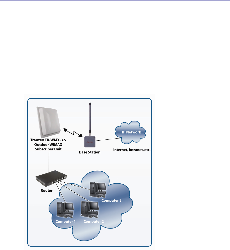
Figure 1-1 shows a configuration example where the TR-WMX-3.5 is connected to the
uplink (WAN) interface on an Ethernet router, hub, or switch. In this configuration, the
TR-WMX-3.5 communicates wirelessly with a base station using its WiMAX interface,
while communicating at 10/100 Mbps with the attached Ethernet device. The TR-WMX-
3.5 also receives its power from the Ethernet connection, eliminating the need to run a
power cable to the TR-WMX-3.5. In this way, the Ethernet device serves as the bridge
between the attached computers and the TR-WMX-3.5.
Figure 1-1. Example of a TR-WMX-3.5 Configuration

Unpacking
TR-WMX-3.5 Subscriber Unit User's Guide
3
1.2 Unpacking
After receiving your TR-WMX-3.5, perform the following steps to ensure that your
contents arrived safely.
Inspect the outer shipping container for damage during shipping. Report any sign of
damage to the appropriate shipping carrier.
Remove the contents from the shipping container.
One TR-WMX-3.5 WiMAX Subscriber Unit
One Power over Ethernet (POE) adapter
An 18 VAC, 24 VAC, or other adapters
One L bracket, boot cover with gasket, and U bolt kit (outdoor unit only)
Inspect your contents thoroughly and compare them to the checked items on the inside
of the shipping carton. If any item is missing or damaged, contact the shipping carrier.
1.3 User-Supplied Items
To complete your installation, please provide the following items:
One 3/8 wrench
One 3/4 wrench
One RJ-45 crimper
A Category 5 Ethernet LAN cable (straight-through or crossover) that is sufficiently long
to bring the signal from the device to the POE adapter
Two RJ-45 jacks
One #6 grounding wire
A personal computer (PC) with a Web browser
An IEEE 802.16-2004-compliant WiMAX base station
Chapter 1, Basic Installation
4 TR-WMX-3.5 Subscriber Unit User's Guide
1.4 Installing the TR-WMX-3.5
The TR-WMX-3.5 can be mounted either horizontally or vertically. Before you install the
unit, determine whether the TR-WMX-3.5 will be mounted horizontally or vertically.
The TR-WMX-3.5 must be installed by a trained professional, value added
reseller, or systems integrator who is familiar with RF cell planning issues and
the regulatory limits defined by the FCC for RF exposure, specifically those
limits outlined in sections 1.1307.
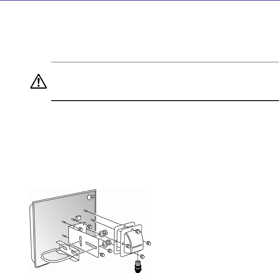
1.4.1 Installing the Outdoor Unit
The following procedure describes how to install the TR-WMX-3.5 Outdoor Subscriber
Unit.
1. Mount the TR-WMX-3.5 at the desired location.
2. Attach the boot cover, L bracket, and U bolt to the TR-WMX-3.5, as shown in Figure
1-2.
Figure 1-2. Attaching the Boot Cover to the TR-WMX-3.5
3. To power the TR-WMX-3.5:
– Connect one end of a Category 5 Ethernet LAN cable to the TR-WMX-3.5 Ethernet
port.
– Connect the other end of the cable to the port labeled CPE on the supplied PoE
adapter.
– Connect the supplied AC adapter to the PoE adapter.
– Plug the AC adapter into an electrical outlet. The TR-WMX-3.5 performs its self-
test for about 30 seconds. Then the TR-WMX-3.5 LEDs show the status of the unit
(see section 1.6.2).
Installing the TR-WMX-3.5
TR-WMX-3.5 Subscriber Unit User's Guide
5
Do not connect a device other than the TR-WMX-3.5 to the CPE port. Network
equipment that does not support PoE can be damaged permanently by
connecting to a PoE source. Most Ethernet interfaces on PCs, laptop/notebook
computers, and other network equipment (such as Ethernet switches and
routers) do not support PoE.
4. If your unit has an external antenna, turn off power to the TR-WMX-3.5, then attach
the antenna to the TR-WMX-3.5 antenna connector. Mount the antenna in a location
that provides the best communication with the base station.
Be sure to turn off power to the TR-WMX-3.5 before mounting the antenna.
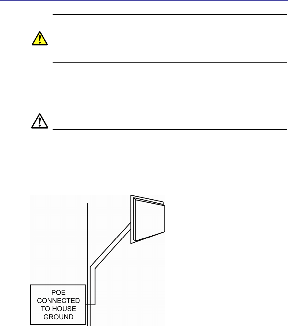
5. Use the Ground terminal on the TR-WMX-3.5 to ground the unit (for best practices,
see section 1.4.3).
Figure 1-3 show an example of the TR-WMX-3.5 installed.
Figure 1-3. Sample TR-WMX-3.5 Installation
Chapter 1, Basic Installation
6 TR-WMX-3.5 Subscriber Unit User's Guide
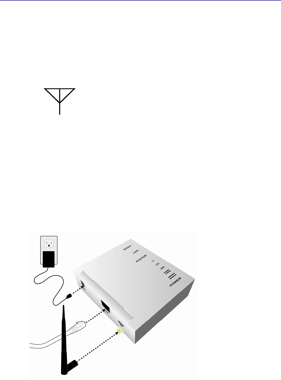
1.4.2 Installing the Indoor Unit
The following procedure describes how to install the TR-WMX-3.5 Indoor Subscriber
Unit. Figure 1-4 shows the steps for installing the indoor unit.
1. Connect the supplied antenna to the antenna connector on the rear of the unit.
Facing the rear of the unit, this is the round connector on the right that is
designated with the following symbol:
2. The TR-WMX-3.5 Indoor Subscriber Unit can be powered by connecting to either an
Ethernet network or an AC outlet. Perform one of the following steps to provide
power the unit:
Connect an Ethernet cable to the RJ-45 jack labeled LAN on the rear panel.
Connect the round end of the supplied power cable to the power connector labeled PWR
on the rear panel. Connect the other end of the cable to a working AC outlet. If
appropriate for your area, use one of the supplied adapters to connect to the AC outlet.
3. Use the signal LEDs on the top panel of the unit to determine signal strength (see
Table 1-4 on page 16). If signal strength is poor, relocate the unit to try and improve
signal strength, as indicated by the status LEDs on the top panel.
Figure 1-4. Installing the Indoor Unit

Installing the TR-WMX-3.5
TR-WMX-3.5 Subscriber Unit User's Guide
7
1.4.3 Installation Best Practices
Observe the following best practices when installing the TR-WMX-3.5.
The TR-WMX-3.5 10/100 Ethernet port auto-senses the cable connected to it and adjusts
automatically. The Ethernet connector is protected with a weatherproof housing. Pin
assignments for this connector are shown in Table 1-1.
Always try to run the Category 5 cable and LMR inside the mounting pole whenever
possible. This helps to insulate the cable form any air surges.
Keep all runs as straight as possible. Never put a full loop into the cables.
The TR-WMX-3.5 antenna’s grounding system must be installed according to Article 810-
15, 810-20, and 810-21 of the National Electric Code, ANSI/NFPA No. 70-1993. Test all
grounds to ensure that they are using a proper Ground. If you use an electrical socket for
Ground, use a socket tester, such as Radio Shack 22-1412. We recommend you obtain a
copy of the National Electric Code Guide and follow its guidelines. If you are in doubt or
have questions about the antenna grounding system, contact a local licensed electrician.
Alternatively, you can drive your own rod and bond it to the house Ground; this way, you
will know that at least one rod is correctly grounded in the system.
Never attach a Grounding wire when the TR-WMX-3.5 is powered. If the Ground is to be
attached to an existing electrical circuit, turn off the circuit before attaching the wire.
Never install radio equipment, such as the TR-WMX-3.5, during an electrical storm. In
addition, to protect your system against damage from lightning, design the system so it
does not attract lightning (it cannot repel lightning, either). National, state, and local
codes are designed to protect life, limb, and property and must always be obeyed. When
in doubt, consult local and national electrical codes or contact an electrician or
professional trained in the design of grounding systems.
Table 1-1. Pin Assignments for the TR-WMX-3.5 10/100 Ethernet Port
Pin Signal Standard Wire Color
1 Tx+ White/Orange
2 Tx- Orange
3 Rx+ White/Green
4 PoE V+ Blue
5 PoE V+ White/Blue
6 Rx- Green
7 Gnd White/Brown
8 Gnd Brown
Chapter 1, Basic Installation
8 TR-WMX-3.5 Subscriber Unit User's Guide
1.5 Configuring the TR-WMX-3.5
After installing the TR-WMX-3.5, use the procedures in the following sections to
configure it using its Configurator.
1.5.1 Logging in to the Configurator
Your TR-WMX-3.5 provides a Web-based Configurator for performing advanced
configuration activities. After you install your TR-WMX-3.5, use the following procedure
to launch the Configurator.
1. Use an Ethernet cable to connect the Ethernet port on the PoE to a network-
interface card (NIC) in a PC or network hub.
The TR-WMX-3.5 Ethernet port is equipped with an auto-sensing Ethernet port
that allows both regular and cross-over cables to be used.
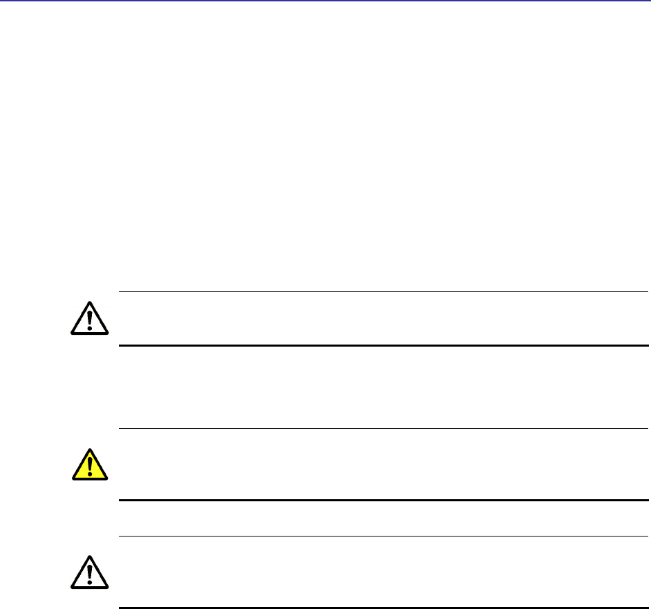
2. Start your Web browser and point it to one of the following default IP addresses:
http://192.168.101.151 or http://192.168.0.1. The Login page in Figure
1-5 appears, with your cursor in the User name field.
The default IP address is the same for all TR-WMX units. Therefore, do not
simultaneously connect multiple unconfigured TR-WMX units to a common
Local Area Network (LAN) and try to access them using the default IP address.
To connect to the Configurator, your PC’s IP address must be on the same
subnet (192.168.101.xxx, where xxx is a number from 1 to 253) as the TR-
WMX-3.5, and the PC’s netmask must be set to 255.255.255.0.
Configuring the TR-WMX-3.5
TR-WMX-3.5 Subscriber Unit User's Guide
9
Figure 1-5. Login Page
3. Enter the default username admin and default case-sensitive password default in
the appropriate fields.
For security, every typed password character appears as a bullet (•). For
additional security, we recommend you change the default password (see
section 4.4.4).
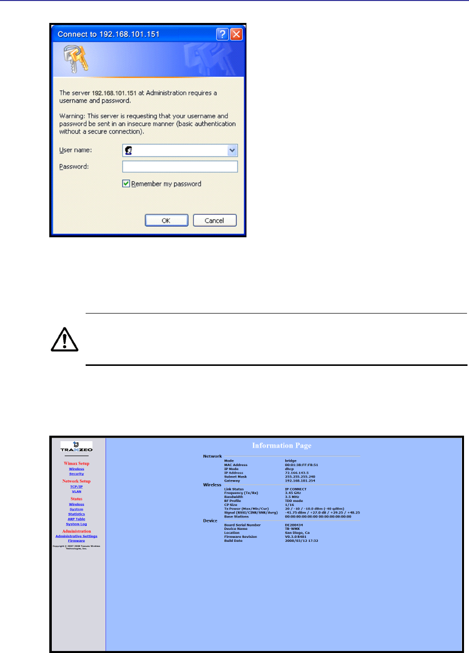
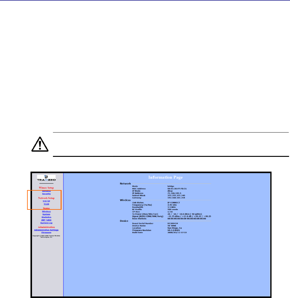
4. Click the OK button to log in. The Information Page appears (see Figure 1-6). This
read-only page displays network, wireless, and device information about your
installation. For more information about this page, see section 3.1.
Figure 1-6. Example of an Information Page

Chapter 1, Basic Installation
10 TR-WMX-3.5 Subscriber Unit User's Guide
1.5.2 Specifying Wireless Settings
After logging in to the Configurator, use the following procedure to set the TR-WMX-3.5
wireless settings.
The default configuration settings for most parameters should work well for
the majority of installations. Only those settings that should be confirmed or
adjusted as part of the quick-start instructions are described in this section.
1. In the left pane, under WiMAX Setup, click Wireless. The Wireless Settings page
appears (see Figure 1-7).
2. Set the three groups of parameters as indicated in Table 1-2 and Figure 1-7.
3. Click the Apply button. A page tells you that your configuration changes have been
saved, but will not be applied until you reboot the TR-WMX-3.5.
4. Do not reboot the TR-WMX-3.5 at this time. Instead, proceed to section 1.5.3 on
page 13.
Configuring the TR-WMX-3.5
TR-WMX-3.5 Subscriber Unit User's Guide
11
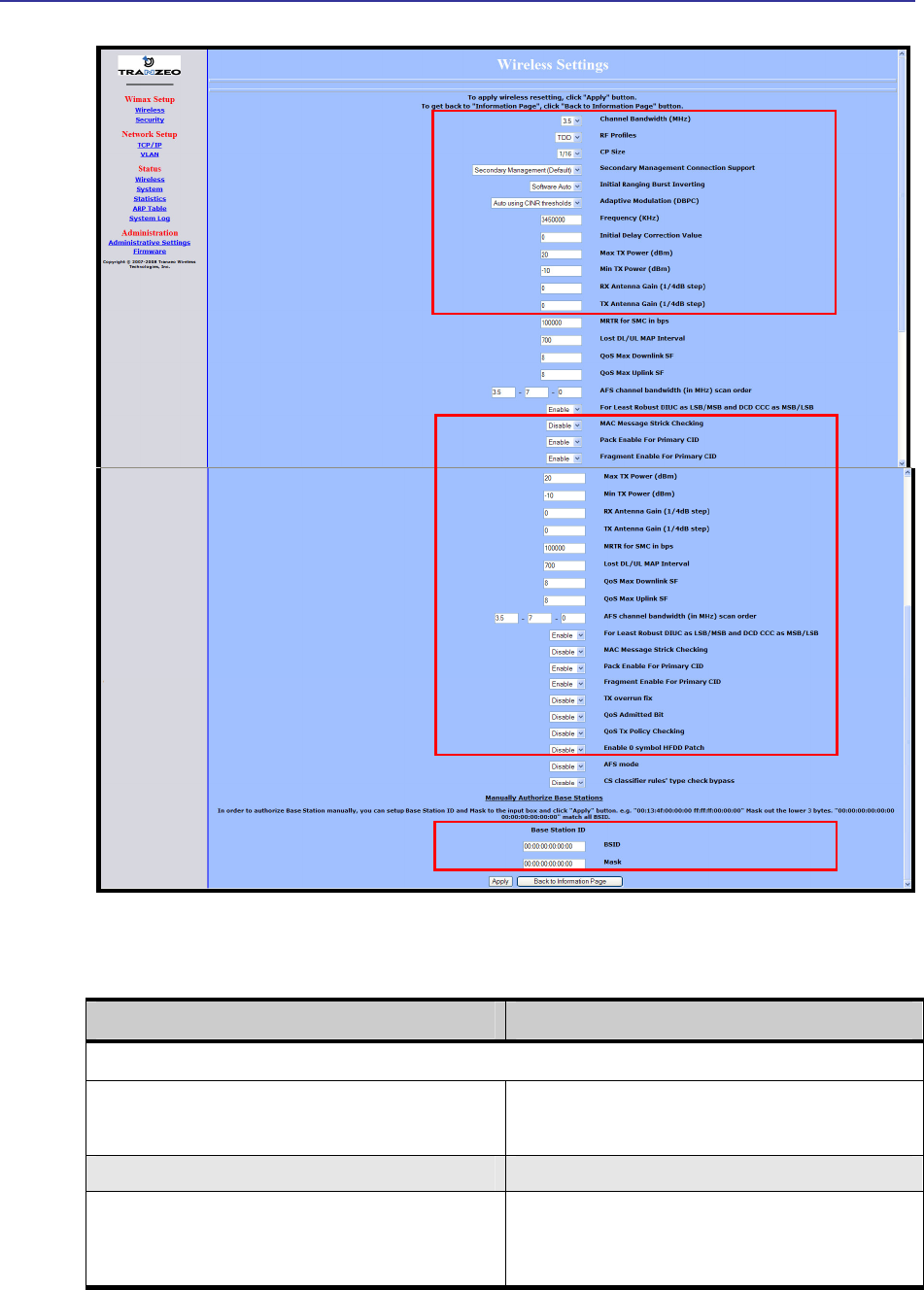
Figure 1-7. Wireless Settings Page
Table 1-2. Wireless Settings
Parameter Choose This Setting
Group ∂ Parameters in Figure 1-7
Channel Bandwidth (MHz) Select 3.5MHz (default) or 7MHz, whichever best suits your
application’s bandwidth needs and is allowed by your license.
The base station must be set to the same bandwidth.
RF Profiles Confirm that the default setting (TDD) is selected.
CP Size Sets the cyclic prefix size, which helps mitigate multipath-
induced signal degradation. Choices are 1/4, 1/8, 1/16
(default), or 1/32. This setting should match the CP setting of
the base station to which the device is connecting.
∂
•
•
÷

Chapter 1, Basic Installation
12 TR-WMX-3.5 Subscriber Unit User's Guide
Parameter Choose This Setting
Secondary Management Connection Support Confirm that the default setting (Secondary Management
Support) is selected. If not, select it.
Initial Ranging Burst Inverting Confirm that the default setting (Software Auto) is selected. If
not, select it.
Adaptive Modulation (DBPC) Confirm that the default setting (Auto using CINR thresholds)
is selected. If not, select it.
Frequency (KHz) Sets the frequency, in kHz. Range is 3650000 – 3675000 in
increments of 250. Default is 3650000 (3.65 GHz).
Initial Delay Correction Value Confirm that the default setting (0) is selected. If not, select it.
Max TX Power (dBm) This value should match the TR-WMX-3.5 antenna.
Examples:
• TR-WMX-3.5-14: specify a value that is 14db less than
the max EIRP setting. If the max EIRP setting is 30dBm,
for example, set Max Tx Power to 16dBm.
• TR-WMX-3.5-17: specify a value that is 17db less than
the max EIRP setting. If the max EIRP setting is 30dBm,
for example, set Max Tx Power to 13dBm.
• TR-WMX-3.5-20: specify a value that is 20db less than
the max EIRP setting. If the max EIRP setting is 30dBm,
for example, set Max Tx Power to 10dBm.
The Max Tx Power value cannot exceed 20dBm. Default
setting is 20.
Note: When setting the Max Tx Power value, do not exceed
the max EIRP allowed by your license. When adding the
values for Tx Antenna Gain and Max Tx Power, the sum of
these values must equal or be less than the max EIRP that
your license allows. The gain of the internal antenna is 17dB,
requiring the Max Tx Power to be set to (max EIRP – 17).
Min Tx Power (dBm) Confirm that the default setting (-10) is selected. If not, select
it.
Rx Antenna Gain (1/4dB step) Confirm that the default setting (0) is selected. If not, select it.
Tx Antenna Gain (1/4dB step) Confirm that the default setting (0) is selected. If not, select it.
Group • Parameters in Figure 1-7
MAC Message Strict Checking Confirm that the default setting (Disable) is selected. If not,
select it.
Pack Enable for Primary CID Confirm that the default setting (Enable) is selected. If not,
select it.
Fragment Enable for Primary CID Confirm that the default setting (Enable) is selected. If not,
select it.
Tx Overrun Fix Confirm that the default setting (Disable) is selected. If not,
select it.
QoS Admitted Bit Confirm that the default setting (Disable) is selected. If not,
select it.
QoS Tx Policy Checking Confirm that the default setting (Disable) is selected. If not,
select it.
Configuring the TR-WMX-3.5
TR-WMX-3.5 Subscriber Unit User's Guide
13
Parameter Choose This Setting
Enable 0 Symbol HDD Patch Confirm that the default setting (Disable) is selected. If not,
select it.
Group ÷ Parameters in Figure 1-7
BSID and Mask Use the standard format for MAC addresses (six 2-digit
hexadecimal numbers separated by colons) to enter the base
station ID. Example: “12:34:56:78:9a:bc”. You can enter up to
8 base station addresses, separating each by pressing the
Enter key. To match all BSIDs, mask out the lower 3 bytes.
"00:00:00:00:00:00 00:00:00:00:00:00" .
1.5.3 Specifying Network Setup Settings
After specifying wireless settings, use the following procedure to specify the network
setup settings.
1. In the left pane, under Network Setup, click TCP/IP. The TCP/IP Settings page
appears (see Figure 1-8).
2. If the TR-WMX-3.5 is set to unmanaged mode (No Secondary Management), set the
parameters in Table 1-3 (these parameters are highlighted in orange in Figure 1-8).
Otherwise, skip to step 3 below.
By default, the TR-WMX-3.5 is set to use secondary managed mode. In this
mode, the settings in Table 1-3 are set automatically and the fields are
unavailable. If you switch to unmanaged mode (No Secondary Management),
you can specify the settings in Table 1-3 manually. To change between the
two modes, use Secondary Management Connection Support on the Wireless
Settings page (see section 2.2.1).
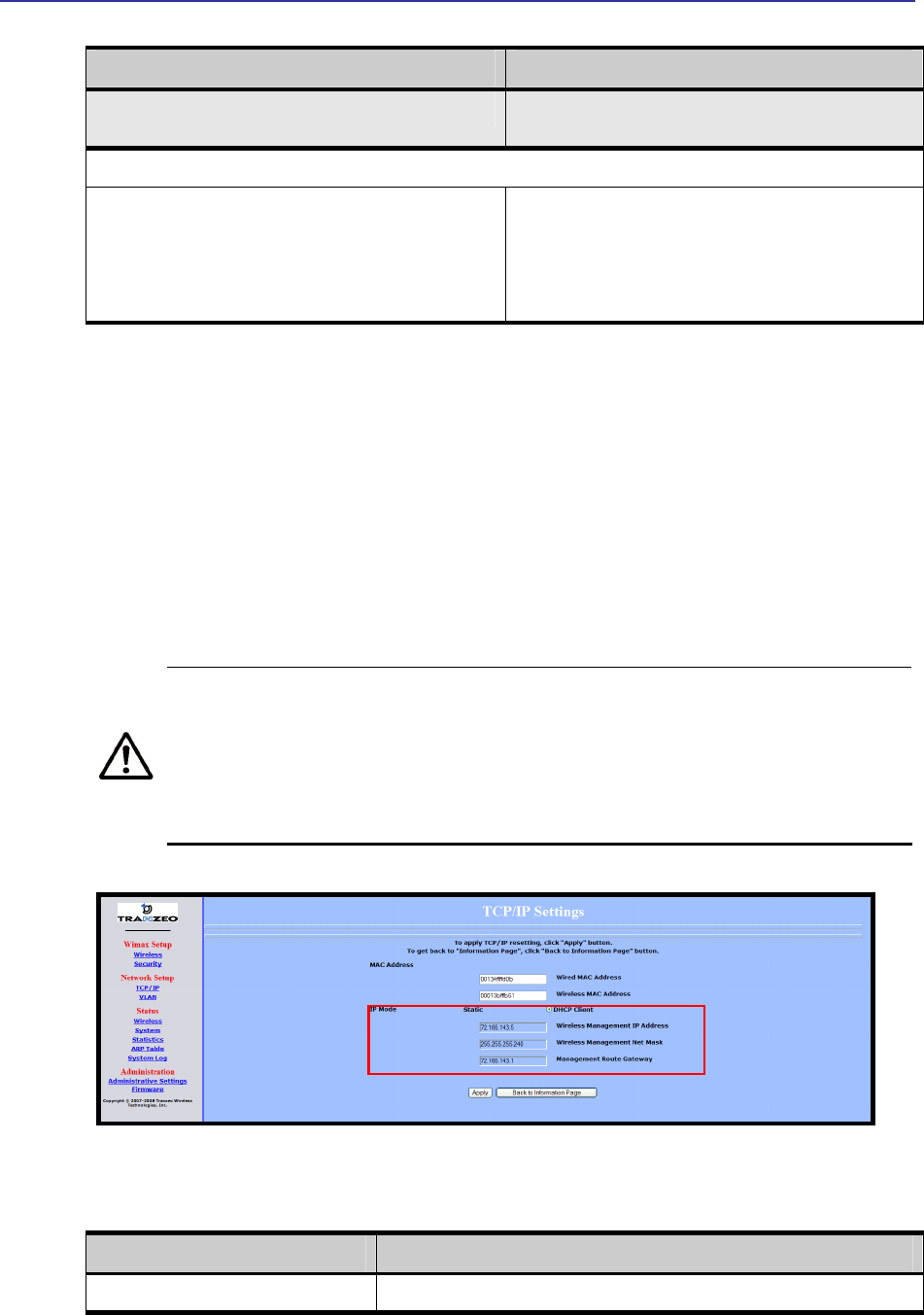
Figure 1-8. TCP IP Settings
Table 1-3. TCP/IP Settings
Parameter Choose This Setting
Wireless IP Address Secondary managed mode: This value is set automatically and the field is
Chapter 1, Basic Installation
14 TR-WMX-3.5 Subscriber Unit User's Guide
Parameter Choose This Setting
unavailable.
Unmanaged mode: Set this parameter to an unused value in the subnet to which
the base station is connected.
Wireless Net Mask Secondary managed mode: This value is set automatically and the field is
unavailable.
Unmanaged mode: Set this value to match that of the subnet to which the base
station is connected.
Route Gateway Secondary managed mode: This value is set automatically and the field is
unavailable.
Unmanaged mode: Set this value to be the router on the subnet to which the base
station is connected.
3. Click the Apply button. When the next page appears, click the Reboot button to
reboot the TR-WMX-3.5 and put your saved settings into effect.
Rebooting disconnects the TR-WMX-3.5 and any connections currently running.
It may take 60 seconds before the TR-WMX-3.5 s running and accessible again.
The Status LED flashes while the unit reboots and goes ON when the unit
completes the reboot process.
Congratulations! You have now completed the installation procedures for your TR-WMX-
3.5 node. Your TR-WMX-3.5 unit is now ready for use.
By default, security is disabled on the TR-WMX-3.5. To enable security, see
section 2.2.2.
Monitoring TR-WMX-3.5 Status
TR-WMX-3.5 Subscriber Unit User's Guide
15
1.6 Monitoring TR-WMX-3.5 Status
There are two ways to monitor the status of your TR-WMX-3.5:
Viewing status pages through the TR-WMX-3.5 Configurator
Watching the status LEDS on the rear panel of the TR-WMX-3.5
1.6.1 Viewing Status Information
You can view TR-WMX-3.5 status information by clicking the links under Status in the
left pane of the Configurator. To display the system information, for example, click
System. For more information, see Chapter 3.
The values shown in the status pages are not updated dynamically. To refresh
the values shown, reload the Web page.
Figure 1-9. Status Links on the Configurator
Status Links
Chapter 1, Basic Installation
16 TR-WMX-3.5 Subscriber Unit User's Guide
1.6.2 Status LEDS
The rear of the TR-WMX-3.5 has 9 LEDs that show the unit’s status. Table 1-4 describes
the functions of the LEDs.
The TR-WMX-3.5 status LEDs can be disabled from the Administrative Settings
page (see section 4.4.3).
Table 1-4. TR-WMX-3.5 LEDs
LED Description
Radio ON = connection with a base station has been established.
OFF = connection with a base station has not been established.
LAN ON = a connection to the Ethernet port has been established.
Flash = connection is in use.
OFF = a connection to the Ethernet port has not been established.
Status ON = TR-WMX-3.5 is fully operational.
Blink = TR-WMX-3.5 is booting or shutting down.
Signal Indicates the received signal strength from a base station.
1 LED blinking = there is no link between the TR-WMX-3.5 and the base station.
1 LED ON = RSSI ≤ -96dBm
2 LEDs ON = -95dBm ≤ RSSI -86 dBm
3 LEDs ON = -85dBm ≤ RSSI ≤ -76 dBm
4 LEDs ON = -75dBm ≤ RSSI ≤ -61 dBm
5 LEDs ON = RSSI ≥ -60 dBm
Power ON = TR-WMX-3.5 is receiving power.
OFF = TR-WMX-3.5 is not receiving power.

17
2 Advanced Configuration
This chapter describes how to perform advanced configuration activities using the TR-
WMX-3.5 Configurator.
This chapter is for expert users who understand networking concepts and
terminology. You do not need to perform these activities to use your TR-
WMX-3.5, nor should you undertake these procedures if you are a novice
user. Performing the instructions in Chapter 1 is all that is required to start
using your TR-WMX-3.5.
The topics covered in this chapter are:
Section 2.1, Understanding the Pages in the Configurator (page 18)
Section 2.2, Entering WiMAX Setup Settings (page 20)
Section 2.3, Entering Network Setup Settings (page 25)
2

Chapter 2, Advanced Configuration
18
2.1 Understanding the Pages in the Configurator
The TR-WMX-3.5 Configurator is a Web-based utility that provides an intuitive user
interface for viewing and changing configuration and status settings.
The page header at the top of the page shows the name of the page. The navigation
panel on the left side provides links you can click to display the pages in the
Configurator. The links are organized into the following categories:
WiMAX Setup - lets you access the pages for viewing and configuring the TR-WMX-3.5
wireless and security settings. See section 2.2.
Network Setup – lets you access the pages for viewing and configuring the TR-WMX-3.5
TCP/IP and VLAN settings. See section 2.3.
Administration – lets you view and configure administrative settings (see section 4) and
upgrade the TR-WMX-3.5 firmware (see Appendix B).
Pages with user-configurable settings have an Apply button at the bottom of the page.
The same pages, and the Firmware page, have a Back to Information Page button.
After you change configuration settings on a page, click Apply before going to another
page; otherwise, your changes will be discarded. Clicking Apply saves in memory all
changes made on the currently displayed page. When you click this button, another page
appears with a Reboot button. You can either click the Reboot button to reboot the TR-
WMX-3.5 and have the new configuration settings take effect, or change settings on
other pages and reboot after all of your configuration changes are complete.
Rebooting disconnects the TR-WMX-3.5 and any connections currently running.
It may take up to 60 seconds before the TR-WMX-3.5 is running and accessible
again. When you reboot the TR-WMX-3.5, the Status LED flashes while the
unit reboots and goes ON when the unit completes the reboot process.
Another way to reboot the unit is by using the Reboot button on the
Administration Settings page (see section 4.3).
The Back to Information Page lets you redisplay the Information Page. This page lets
you view the TR-WMX-3.5’s current network, wireless, and device settings (see section
3.1). This page is the first page that appears when you log in to the Configurator.
The main panel is the viewing area on the page. When you select a link in the navigation
panel, the fields of the page are displayed in the main panel. This is where you view
and change the TR-WMX-3.5 configuration settings.
Understanding the Pages in the Configurator
TR-WMX-3.5 Subscriber Unit User's Guide
19
The remaining sections describe the Configurator pages you can use to view and change
the TR-WMX-3.5 configuration and status. These sections assume you used the
procedure in section 1.5.1 to log in to the Configurator.
Figure 2-1. Areas on the Configurator Page
Navigation
Panel
Main Area
Page Header
Chapter 2, Advanced Configuration
20 TR-WMX-3.5 Subscriber Unit User's Guide
2.2 Entering WiMAX Setup Settings
The Configurator provides two menu selections for entering WiMAX setup settings:
Wireless lets you set wireless settings for the TR-WMX-3.5. See section 2.2.1.
Security lets you set security settings for the TR-WMX-3.5. See section 2.2.2.
If you change any of the settings on these pages, click the Apply button at the bottom
of the page to reboot the TR-WMX-3.5 and have your settings take effect.
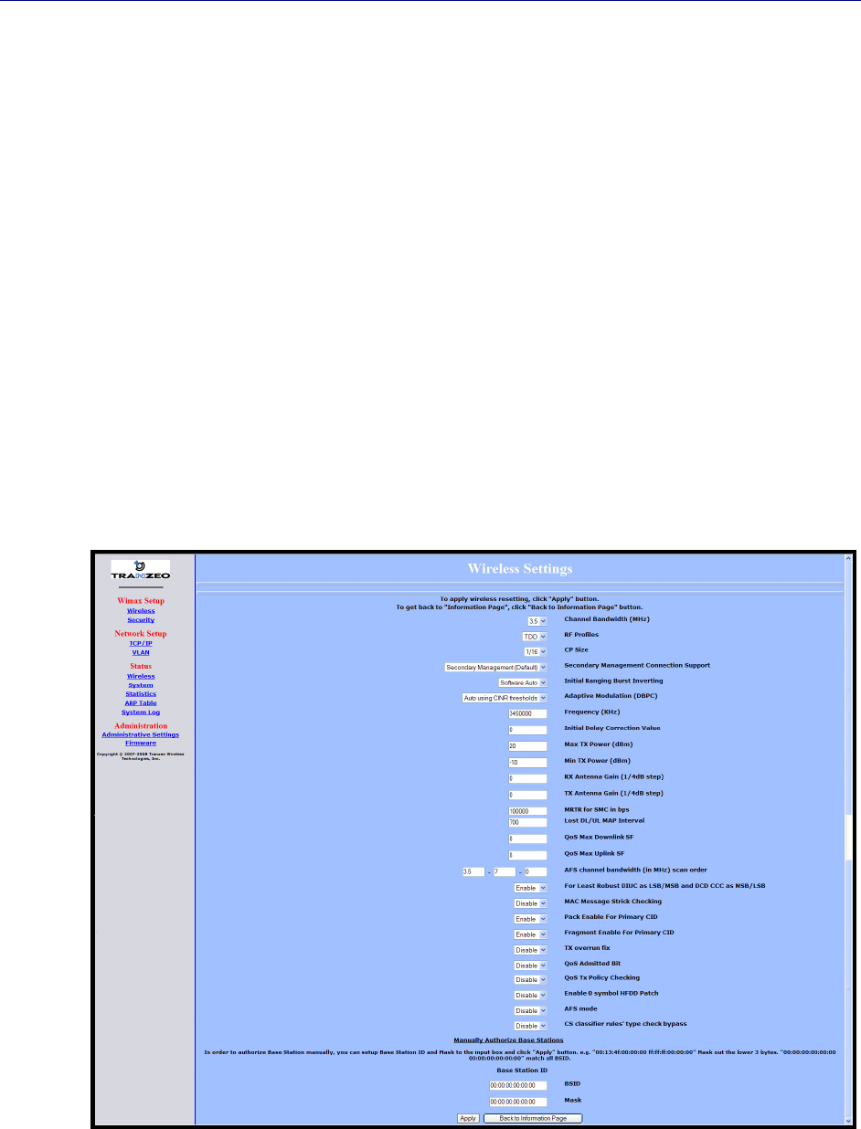
2.2.1 Entering Wireless Settings
Clicking the Wireless link under WiMAX Setup in the left pane of the Configurator
displays the Wireless Settings page. Use this page to select the wireless settings for the
TR-WMX-3.5. Figure 2-2 shows this page, and Table 2-1 describes the fields and buttons
on it.
Figure 2-2. Wireless Settings Page

Entering WiMAX Setup Settings
TR-WMX-3.5 Subscriber Unit User's Guide
21
Table 2-1. Fields and Buttons in the Wireless Settings Page
Field Description
Channel Bandwidth (MHz) Select the value that best suits your application’s bandwidth needs and is allowed by
your license. Choices are:
• 3.5 MHz (default)
• 7MHz
RF Profiles Select the duplex method that best suits your requirements. Choices are:
• TDD mode: sets the carrier frequency for communication between the CPE
and base station. (default)
• H-FDD mode: sets the carrier frequency for communication from the base
station to the CPE.
CP Size Sets the cyclic prefix size, which helps mitigate multipath-induced signal
degradation. The setting reflects the ratio of the guard band to the signal band (i.e.,
a smaller fraction implies a larger guard band). This setting should match the CP
setting of the base station to which the device is connecting.
Choices are:
• 1/4
• 1/8
• 1/16 (default)
• 1/32
Secondary Management Connection
Support
Determines whether the TR-WMX-3.5 is configured for Static or DHCP Client mode.
Choices are:
• No Secondary Management Support – unmanaged mode. This setting requires
you to set the TR-WMX-3.5 IP addresses manually. This setting makes the
Management Net Mask, and Management Route Gateway fields available on
the TCP/IP Settings page.
• Secondary Management (Default) – Secondary managed mode. Select this
setting if the TR-WMX-3.5 IP addresses will be set automatically by a DHCP
server. This setting makes Management Net Mask, and Management Route
Gateway fields on the TCP/IP Settings page unavailable. (default)
Initial Ranging Burst Inverting This feature is provided for Engineering development use, and is an undocumented
feature. Please do not change from the default selection of Software Auto.

Chapter 2, Advanced Configuration
22 TR-WMX-3.5 Subscriber Unit User's Guide
Field Description
Adaptive Modulation (DBPC) Matches the downlink modulation used to the link conditions. Adaptive modulation,
operates in conjunction with the downlink burst power control (DBPC) which adjusts
the CPE transmit power to that requested by the base station. Fixed modulations
can be selected or adaptive algorithms based on CINR or based on error rates can
be used to determine when the downlink modulation is adjusted. Choices are::
• Disable DBPC
• Auto using CINR thresholds (default)
• Auto using BER thresholds
• Fixed to BPSK–1/2
• Fixed to QPSK–1/2
• Fixed to QPSK–3/4
• Fixed to QAM16–1/2
• Fixed to QAM16–3/4
• Fixed to QAM64–2/3
• Fixed to QAM64–3/4
Frequency (KHz) Sets the frequency, in kHz. Range is 3650000 – 3675000 in increments of 250.
Default is 3650000 (3.65 GHz).
Initial Delay Correction Value 0 (default)
Max TX Power (dBm) The maximum transmit power at which the unit can operate, specified in dBm. This
value added to the Tx Antenna Gain cannot exceed the EIRP that the operator
license allows. Range is -10 to 20dBm. Default is 20dBm.
Min Tx Power (dBm) The minimum transmit power at which the unit can operate, specified in dBm. Range
is -10 to 20dBm. Default is -10dBm.
Rx Antenna Gain (1/4dB step) The gain of the Rx antenna, in dB. The gain of the internal antenna is 17dB. Default
is 0dB.
Tx Antenna Gain (1/4dB step) The gain of the Rx antenna, in dB. The gain of the internal antenna is 17dB. Default
is 0dB.
MRTR for SMC in bps Sets the minimum reserved traffic rate for the secondary management channel.
Default is 100000.
Lost DL/UL MAP Interval Sets the time in seconds that the CPE will maintain the link to the BS using the last
DL or UL MAP received. Default is 700.
QoS Max Downlink SF Sets the maximum number of downlink service flows the CPE will support. Default is
8.The maximum possible SF for downlink and uplink service flows, combined is 60.
QoS Max Uplink SF Sets the maximum number of uplink service flows the CPE will support. Default is
8.The maximum possible SF for downlink and uplink service flows, combined is 60.
AFS channel bandwidth (in MHz) scan
order
This feature is provided for Engineering development use, and is an undocumented
feature. Please do not change from the default selection.
For Least Robust DIUC as LSB/MSB and
DCD CCC as MSB/LSB
This feature is provided for Engineering development use, and is an undocumented
feature. Please do not change from the default selection.
MAC Message Strict Checking This feature is provided for Engineering development use, and is an undocumented
feature. Please do not change from the default selection.

Entering WiMAX Setup Settings
TR-WMX-3.5 Subscriber Unit User's Guide
23
Field Description
Pack Enable for Primary CID This feature is provided for Engineering development use, and is an undocumented
feature. Please do not change from the default selection.
Fragment Enable for Primary CID This feature is provided for Engineering development use, and is an undocumented
feature. Please do not change from the default selection.
Tx Overrun Fix This feature is provided for Engineering development use, and is an undocumented
feature. Please do not change from the default selection.
QoS Admitted Bit This feature is provided for Engineering development use, and is an undocumented
feature. Please do not change from the default selection.
QoS Tx Policy Checking This feature is provided for Engineering development use, and is an undocumented
feature. Please do not change from the default selection.
Enable 0 Symbol HDD Patch This feature is provided for Engineering development use, and is an undocumented
feature. Please do not change from the default selection.
AFS Mode This feature is provided for Engineering development use, and is an undocumented
feature. Please do not change from the default selection.
CS classifier rules' type check bypass This feature is provided for Engineering development use, and is an undocumented
feature. Please do not change from the default selection.
BSID and Mask Use the standard format for MAC addresses (six 2-digit hexadecimal numbers
separated by colons) to enter the base station ID. Example: “12:34:56:78:9a:bc”.
You can enter up to 8 base station addresses, separating each by pressing the
Enter key. To match all BSIDs, mask out the lower 3 bytes. "00:00:00:00:00:00
00:00:00:00:00:00" .
Chapter 2, Advanced Configuration
24 TR-WMX-3.5 Subscriber Unit User's Guide
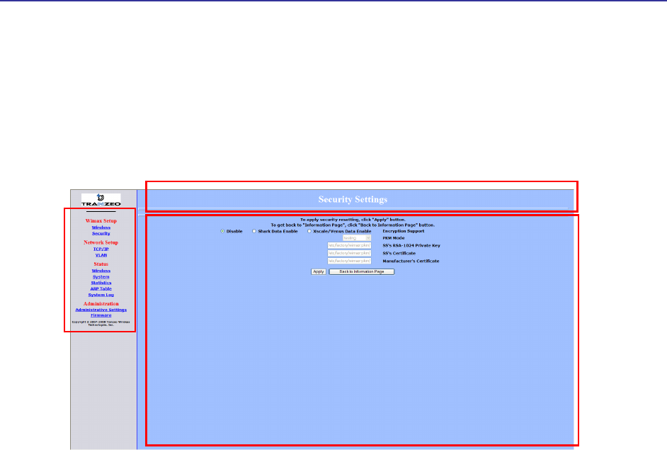
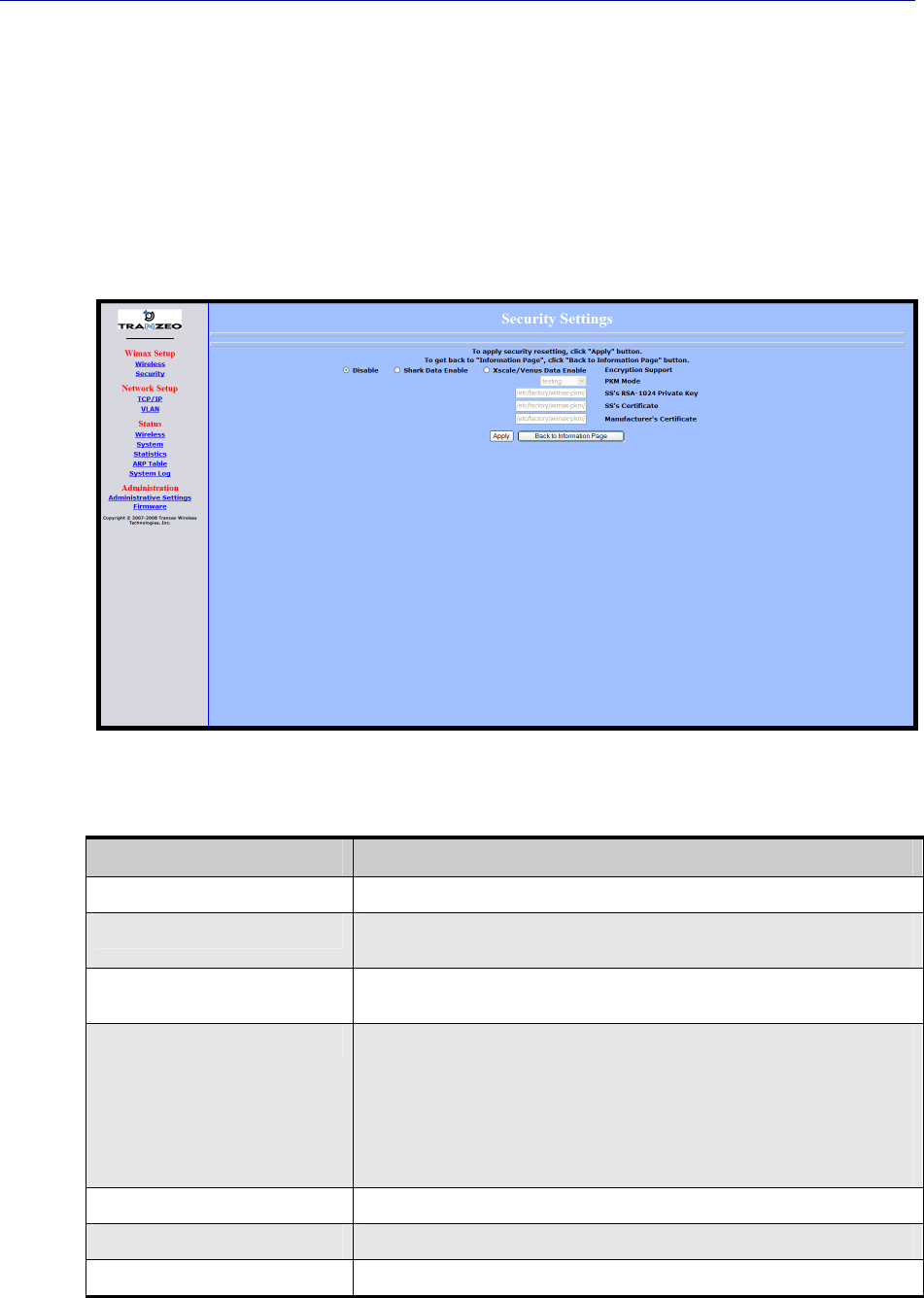
2.2.2 Setting Security Settings
Clicking the Security link under WiMAX Setup in the left pane of the Configurator
displays the Security Settings page. Use this page to select the security settings for the
TR-WMX-3.5. The first selection on this page lets you select the encryption method to
be used. Depending on your selection, the remaining fields on the page are either
enabled or disabled. Figure 2-3 shows this page, and Table 2-2 describes the fields and
buttons on it.
Figure 2-3. Security Settings Page
Table 2-2. Fields and Buttons in the Security Settings Page
Field Description
Disable Disables the TR-WMX-3.5 security settings on this page. This is the default setting.
Shark Data Enable This feature is provided for Engineering development use, and is an undocumented
feature. Please do not change from the default selection.
Xscale/Venus Data Enable This feature is provided for Engineering development use, and is an undocumented
feature. Please do not change from the default selection.
PKM Mode Enable the privacy key management (PKM) protocol used to distribute and maintain
private keys for traffic encryption. Choices are:
• Testing – select this setting if the TR-WMX-3.5 will be used for testing/evaluation
purposes. (default)
• Operational – select this setting if the TR-WMX-3.5 will be used for network
operations.
SS's RSA-1024 Private Key Specify the path where the RAS 1024 private key is located.
SS's Certificate Specify the path where the subscriber station’s certificate is located.
Manufacturer's Certificate Specify the path where the manufacturer’s certificate is located.
Entering Network Setup Settings
TR-WMX-3.5 Subscriber Unit User's Guide
25
2.3 Entering Network Setup Settings
The Configurator provides two menu selections for entering network setup settings:
TCP/IP lets you set the MAC address and IP mode for the TR-WMX-3.5. See section 2.3.1.
VLAN lets you set the virtual LAN (VLAN) settings for the TR-WMX-3.5. See section 0.
If you change any of the settings on these pages, click the Apply button at the bottom
of the page to reboot the TR-WMX-3.5 and have your settings take effect.
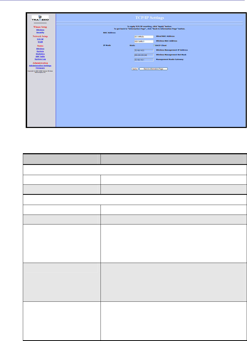
2.3.1 Entering TCP/IP Settings
Clicking the TCP/IP link under Network Setup in the left pane of the Configurator
displays the TCP/IP Settings page. Use this page to select the wireless settings for the
TR-WMX-3.5. Figure 2-4 shows this page, and Table 2-3 describes the fields and buttons
on it.
By default, the TR-WMX-3.5 is set to secondary managed mode. In this mode,
the IP Mode settings in Table 2-3 are set automatically and the fields are
unavailable. If you switch to unmanaged mode (No Secondary Management),
you can specify these settings manually. To change between the two modes,
use Secondary Management Connection Support on the Wireless Settings
page (see section 2.2.1).
If you change the unit’s MAC address from those assigned when the unit was
shipped and noted on the Subscriber Unit label, please ensure that the MAC of
the Wireless MAC address is a lower number than the Wired MAC address.
Chapter 2, Advanced Configuration
26 TR-WMX-3.5 Subscriber Unit User's Guide
Figure 2-4. TCP/IP Settings Page
Table 2-3. Fields and Buttons in the TCP/IP Settings Page
Field Description
MAC Address
Wired MAC Address The TR-WMX-35’s wired MAC address.
Wireless MAC Address The TR-WMX-35’s wireless MAC address.
IP Mode
Static The TR-WMX-35 IP address will be set manually and remain static.
DHCP Client The TR-WMX-35 IP address will be set automatically using DHCP.
Wireless Management IP Address The wireless management IP address of the TR-WMX-35.
• Secondary managed mode: This value is set automatically and the field is
unavailable.
• Unmanaged mode: Set this value to an unused IP address in the subnet to
which the base station is connected.
Wireless Management Net Mask The wireless management netmask of the TR-WMX-35.
• Secondary managed mode: This value is set automatically and the field is
unavailable.
• Unmanaged mode: Set this value to match that of the subnet to which the
base station is connected.
Management Route Gateway The wireless management gateway of the TR-WMX-35.
• Secondary managed mode: This value is set automatically and the field is
unavailable.
• Unmanaged mode: Set this value to be the router on the subnet to which the
base station is connected.
Entering Network Setup Settings
TR-WMX-3.5 Subscriber Unit User's Guide
27
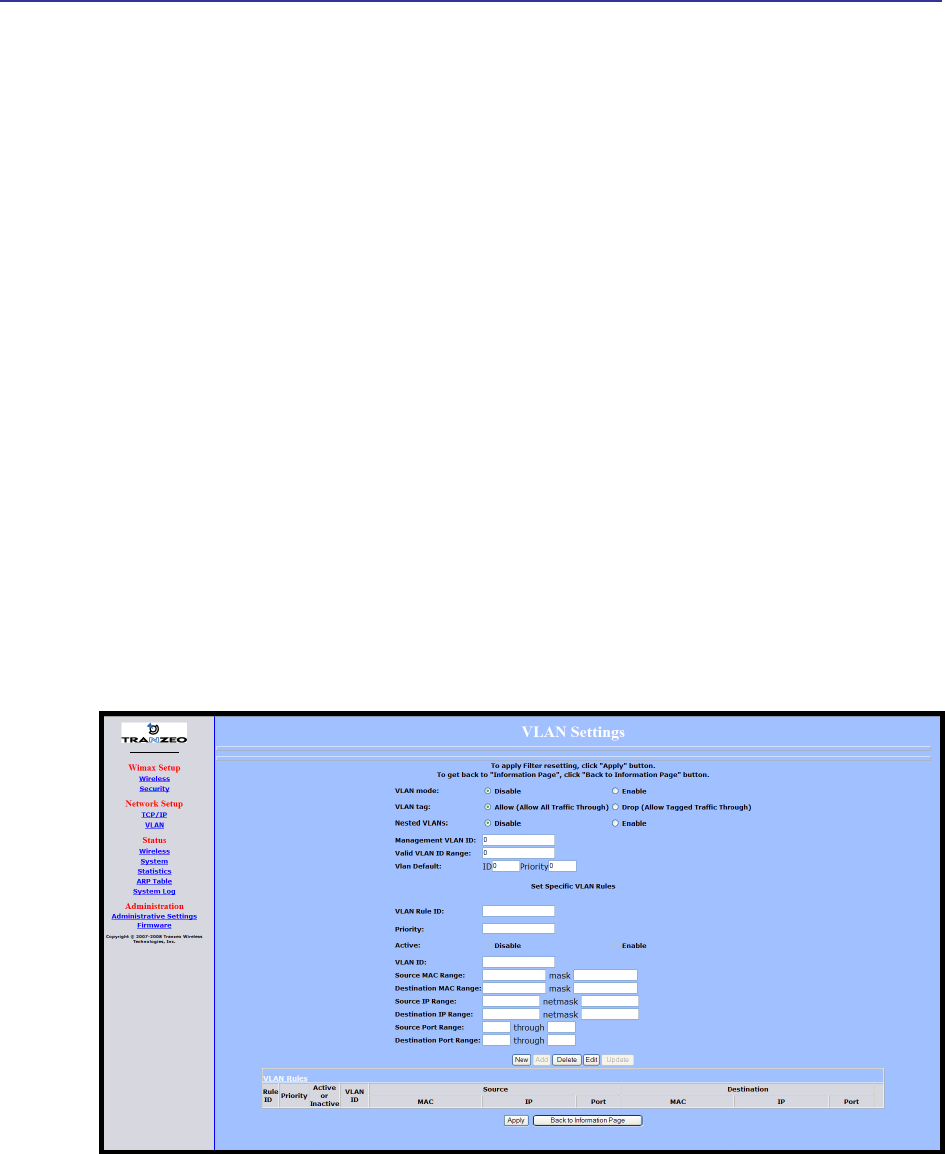
2.3.2 VLAN Settings
A VLAN is an administrative grouping of network devices that is logically segmented, by
functions, project teams, or applications rather than a physical or geographical basis.
VLANs provide the segmentation services traditionally provided by routers in LAN
configurations. For example, all workstations and servers used by a particular workgroup
team can be connected to the same VLAN, regardless of their physical connections to
the network. In this way, you can use VLANs to reconfigure the network through
software rather than physically unplugging and moving devices or wires.
Clicking the VLAN link under Network Setup in the left pane of the Configurator
displays the VLAN Settings page. Use this page to select the security settings for the TR-
WMX-3.5. Figure 2-5 shows this page, and Table 2-4 describes the fields and buttons on
it.
The VLAN Settings page is divided into four areas:
The top area lets you enable and configure the management VLAN.
The middle area lets you define rules for the management VLAN.
Buttons below the rules area let you add, edit, delete, and update a management VLAN.
The bottom of the page shows the VLAN rules that have been defined.
Figure 2-5. VLAN Settings Page

Chapter 2, Advanced Configuration
28 TR-WMX-3.5 Subscriber Unit User's Guide
Table 2-4. Fields and Buttons in the VLAN Settings Page
Field Description
VLAN Mode Lets you enable or disable VLAN mode. Choices are:
• Enable – enables VLAN mode, enabling the settings on this page.
• Disable – disables VLAN mode, disabling the settings on this page. (default)
VLAN Tag Tagging refers to the IEEE 802.1Q header that is inserted into the standard Ethernet header.
Choices are:
• Allow – a Tag Header is added to the frame after the destination and source MAC
addresses. This information is preserved as the frame moves through the network..
(default)
• Drop – a Tag Header is not added to the frame.
Nested VLANs Nested VLANs (also known as VLAN double tagging) are used to overlay a private Layer 2
network over a public Layer 2 network. This provides simple access to an infrastructure of
network service providers in networks. With a nested VLAN configuration, each customer is
given a customer-ID, which is a unique identifier within the service provider infrastructure.
Traffic from individual customers is tagged with the customer-ID and segregated from other
customer’s traffic.
• Disable – disables nested VLANs. (default)
• Enable – enables nested VLANs.
Management VLAN ID The numeric identifier for the management VLAN. Default is 0.
Valid VLAN ID Range To specify a range of VLAN IDs, enter the first and last numbers, separated by a dash (for
example, 100-200). Default is 0.
VLAN Default The default ID and priority of the VLAN. Defaults are 0 for ID and Priority.
Set Specific VLAN Rules
VLAN Rule ID You can create a VLAN identification matching rule that is based on a single VLAN ID or
priority, a range of IDs or priorities, or any ID or priority.
Priority Specify a single VLAN priority, a range of VLAN priorities, or a VLAN priority for any traffic
flow.
• To specify a single VLAN priority, enter a number between 0 and 7 (0 has the highest
priority and 7 has the lowest priority).
• To specify a range of VLAN priorities, enter the first and last numbers, separated by a
dash (for example, 1-3).
• To match any traffic flow that has a VLAN priority tag, type the word any.
Active Select whether the rule is enabled or disabled. Choices are:
• Disable – rule is not in effect.
• Enable – rule is in effect.
VLAN ID Enter the VLAN ID of the rule you want to edit or delete.
Source MAC Range The range of source MAC addresses to which the rule applies and corresponding mask.
Destination MAC Range The range of destination MAC addresses to which the rule applies and corresponding mask.

Entering Network Setup Settings
TR-WMX-3.5 Subscriber Unit User's Guide
29
Set Specific VLAN Rules (continued)
Field Description
Source IP Range The range of source IP addresses to which the rule applies and corresponding mask.
Destination IP Range The range of destination IP addresses to which the rule applies and corresponding mask.
Source Port Range The range of source ports to which the rule applies and corresponding mask.
Destination Port Range The range of destination ports to which the rule applies and corresponding mask.
Button Description
New Click this button to set up a new rule for the management VLAN. After clicking this button,
complete the Set Specific VLAN Rules section on this page and click Add. The new rule
appears under VLAN Rules at the bottom of this page.
Add After setting up a new rule, click this button to add the rule to the VLAN Rules list at the
bottom of the page.
Delete Lets you delete a rule. In the VLAN Rule ID field, enter the ID for the rule you want to delete.
Then click Delete to delete the rule.
Note: No precautionary message appears before deleting a rule, so be sure you do not need
the rule before you delete it.
Edit Lets you modify a rule. In the VLAN Rule ID field, enter the ID for the rule you want to edit.
Then click Edit, change the settings, and click Update.
Update Click this button after editing a rule.

Chapter 2, Advanced Configuration
30 TR-WMX-3.5 Subscriber Unit User's Guide
This page intentionally left blank.

31
3 Viewing Status Information
The Configurator provides a Status section that lets you display status pages for
monitoring the TR-WMX-3.5. This section describes how to use these pages to monitor
the TR-WMX-3.5.
The topics covered in this chapter are:
Section 3.1, Information Page (page 32)
Section 3.2, Wireless Information Page (page 34)
Section 3.2, Wireless Information Page (page 34)
Section 3.3, System Information Page (page 36)
Section 3.4, Statistics Information Page (page 38)
Section 3.5, ARP Information Page (page 40)
Section 3.6, System Log (page 41)
3
Chapter 3, Viewing Status Information
32 TR-WMX-3.5 Subscriber Unit User's Guide
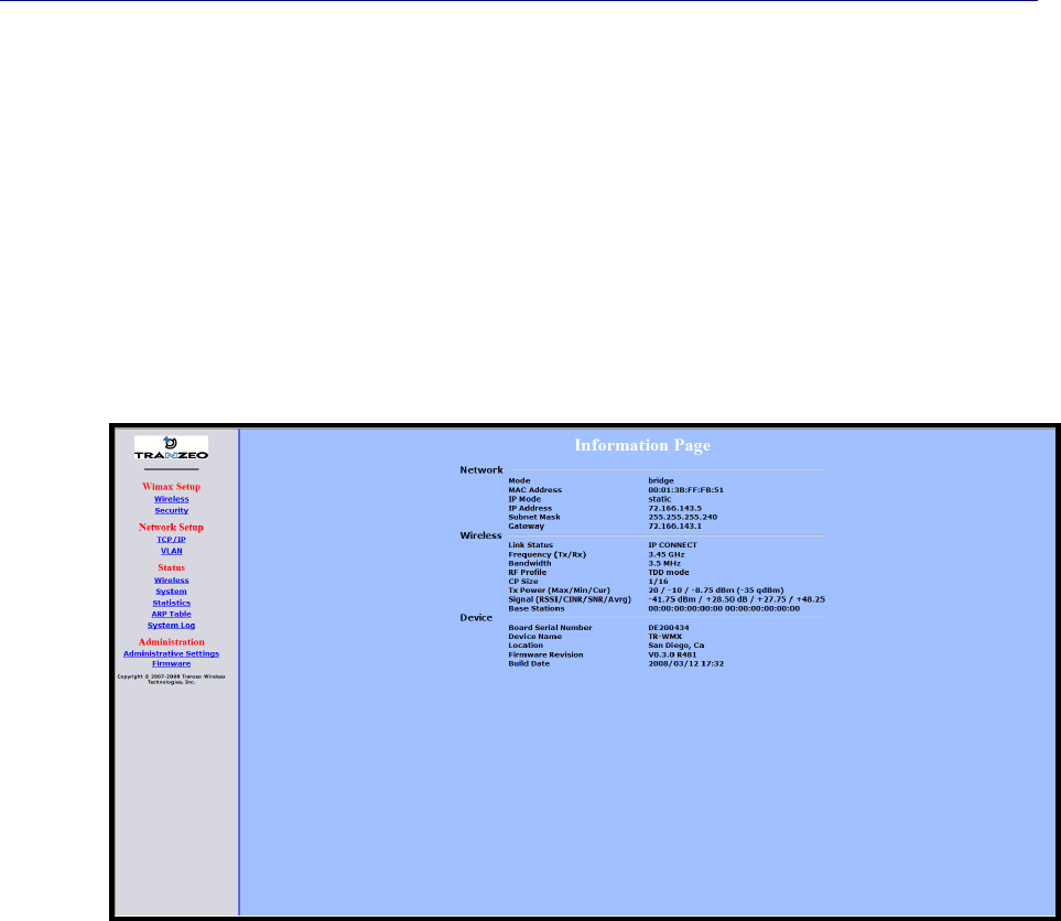
3.1 Information Page
The Information Page is the first page that appears when you log in to the Configurator.
You can also display this page from another page in the Configurator by clicking the
Back to Information Page button at the bottom of the pages in the WiMAX Setup,
Network Setup, and Administration sections.
The Information Page is a read-only page that displays network, wireless, and device
information. Figure 3-1 shows this page and Table 3-1 describes the fields on it.
Figure 3-1. Information Page

Information Page
TR-WMX-3.5 Subscriber Unit User's Guide
33
Table 3-1. Information Page
Field Description
Network
Mode TR-WMX operating mode (for example, bridge, router, etc.).
MAC Address TR-WMX Media Access Control (MAC) address, as defined on the TCP/IP Settings page (see
section 2.3.1).
IP Mode IP mode of the TR-WMX-3.5, as defined on the TCP/IP Settings page (see section 2.3.1).
IP Address IP address of the TR-WMX-3.5.
Subnet Mask Subnet mask of the TR-WMX-3.5.
Gateway Gateway mask of the TR-WMX-3.5.
Wireless
Link Status Shows whether the TR-WMX-3.5 is connected to the base station.
Frequency (Tx/Rx) TR-WMX-3.5 transmit and receive frequencies, as defined on the Wireless Settings page (see
section 3.2).
Bandwidth Bandwidth used by the TR-WMX-3.5.
RF Profile TR-WMX-3.5 duplex method, as defined on the Wireless Settings page (see section 3.2).
CP Size TR-WMX-3.5 cyclic prefix size, as define on the Wireless Settings page (see section 3.2).
Tx Power (Max/Min/Cur) TR-WMX-3.5 maximum, minimum, and current transmit power levels, in dBm. The maximum and
minimum settings are defined on the Wireless Settings page (see section 3.2).
Signal
(RSSI/CINR/SNR/Avrg)
RSSI, CINR, SNR, and average signal strength, in dBm.
• RSSI - the higher the value, the higher the transmit rate (up to the maximum). Conversely, the
lower the RSSI, the lower the transmission speed until 0 is reached (no connectivity).
• CINR - the higher the value, the more throughput a link can maintain.
• SNR - the lower the value means the desired signal is nearly indistinguishable from the
unwanted noise.
• Avrg - the average of the RSSI, CINR, and SNR values.
Base Stations MAC address with which the TR-WMX-3.5 is communicating, as defined on the Wireless Settings
page (see section 3.2).
Device
Board Serial Number Serial number of the TR-WMX-3.5 printed circuit board.
Device Name Name of the TR-WMX-3.5 unit, as defined on the Administrative Settings page (see section 4.4.1).
Default is TR-WMX.
Location Location of the TR-WMX-3.5, as defined on the Administrative Settings page (see Chapter 4).
Firmware Revision Revision number of the firmware used by the TR-WMX-3.5.
Build Date Build date of the firmware used by the TR-WMX-3.5.
Chapter 3, Viewing Status Information
34 TR-WMX-3.5 Subscriber Unit User's Guide
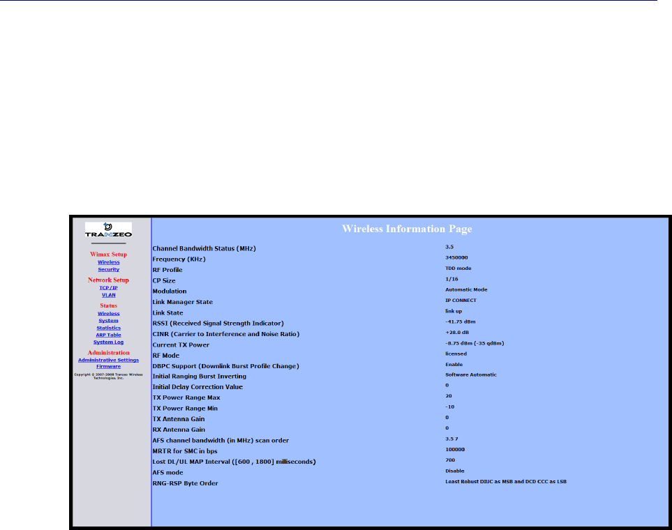
3.2 Wireless Information Page
The Wireless Information page shows information about the TR-WMX-3.5’s wireless
operation. The user-configurable information on this page can be set using the Wireless
Settings page (see section 2.2.1). Figure 3-2 shows this page and Table 3-2 describes the
fields on it.
Figure 3-2. Wireless Information Page

Wireless Information Page
TR-WMX-3.5 Subscriber Unit User's Guide
35
Table 3-2. Wireless Information Page
Field Description
Channel Bandwidth
Status (MHz)
Bandwidth, in MHz, of theTR-WMX-3.5, as defined on the Wireless Settings page (see section
2.2.1).
Frequency (KHz) Frequency, in kHz, of theTR-WMX-3.5, as defined on the Wireless Settings page (see section
2.2.1).
RF Profile RF profile of theTR-WMX-3.5, as defined on the Wireless Settings page (see section 2.2.1).
CP Size Cycle prefix size, as defined on the Wireless Settings page (see section 2.2.1).
Modulation Modulation used by theTR-WMX-3.5.
Link Manager State Shows where in the network connection process the CPE is. For example if the CPE is scanning
for a BS downlink message, receiving a DHCP address assignment, or if the CPE to BS link is
operational.
Link State Shows whether the TR-WMX-3.5 link is up or down.
RSSI (Received Signal
Strength Indicator)
Strength of the Received Signal Strength Indicator, in dBm, received by your TR-WMX-3.5. The
higher the value, the higher the transmit rate (up to the maximum). Conversely, the lower the RSSI,
the lower the transmission speed until 0 is reached (no connectivity).
CINR (Carrier to
Interference and Noise
Ratio)
Carrier to Interference and Noise Ratio, in dB, for your TR-WMX-3.5. The higher the value, the
more throughput a link can maintain.
Current TX Power Current transmit power, in dBm, for your TR-WMX-3.5.
RF Mode Current radio-frequency mode (licensed or unlicensed) for your TR-WMX-3.5.
DBPC Support (Downlink
Burst Profile Change)
Shows whether Downlink Burst Profile Change is enabled or disabled.
Initial Ranging Burst
Inverting
This feature is provided for Engineering development use, and is an undocumented feature.
Initial Delay Correction
Value
This feature is provided for Engineering development use, and is an undocumented feature.
TX Power Range Max The maximum transmit power range of the TR-WMX-3.5, as defined on the Wireless Settings page
(see section 2.2.1).
TX Power Range Min The minimum transmit power range of the TR-WMX-3.5, as defined on the Wireless Settings page
(see section 2.2.1).
TX Antenna Gain The maximum transmit antenna gain of the TR-WMX-3.5, as defined on the Wireless Settings page
(see section 2.2.1).
RX Antenna Gain The minimum transmit antenna gain of the TR-WMX-3.5, as defined on the Wireless Settings page
(see section 2.2.1).
AFS Channel Bandwidth
(in MHz) Scan Order
This feature is provided for Engineering development use, and is an undocumented feature.
MRTR for SMC in bps The minimum reserved traffic rate for the secondary management channel.
Lost DL/UL MAP Interval
([600 , 1800]
milliseconds)
The time in seconds that the CPE will maintain the link to the BS using the last DL or UL MAP
received.
AFS Mode This feature is provided for Engineering development use, and is an undocumented feature.
RNG-RSP Byte Order This feature is provided for Engineering development use, and is an undocumented feature.
Chapter 3, Viewing Status Information
36 TR-WMX-3.5 Subscriber Unit User's Guide
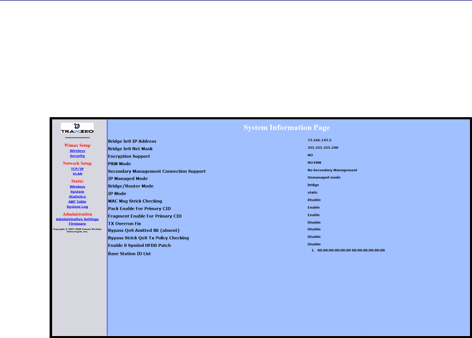
3.3 System Information Page
The System Information page shows information about the TR-WMX-3.5’s wireless
configuration settings and operation. Figure 3-3 shows this page and Table 3-3 describes
the fields on it.
Figure 3-3. System Information Page

System Information Page
TR-WMX-3.5 Subscriber Unit User's Guide
37
Table 3-3. System Information Page
Field Description
Bridge br0 IP Address Wired IP address of the TR-WMX-3.5, as defined on the TCP/IP Settings page (see section 2.3.1).
Bridge br0 Net Mask Wired netmask of the TR-WMX-3.5, as defined on the TCP/IP Settings page (see section 2.3.1).
Encryption Support Shows whether encryption is enabled or disabled on the TR-WMX-3.5, as defined on the Security
Settings page (see section 2.2.2).
PKM Mode Shows whether private key management is enabled or disabled on the TR-WMX-3.5, as defined on
the Security Settings page (see section 2.2.2).
Secondary Management
Connection Support
Shows whether the secondary management support has been enabled.
IP Managed Mode Shows whether an IP address has been assigned to the CPE using DHCP operating over the IEEE
802.16 secondary management channel.
Bridge/Router Mode Shows whether the TR-WMX-3.5 is configured for bridge or router mode, as defined on the TCP/IP
Settings page (see section 2.3.1).
IP Mode Shows whether IP mode is set to static or DHCP setting, as defined on the TCP/IP Settings page
(see section 2.3.1).
MAC Msg Strict Checking Shows whether MAC Message Strict Checking is enabled or disabled, as defined on the Wireless
Settings page (see section 2.2.1).
Pack Enable For Primary
CID
Shows whether Pack Enable for Primary CID is enabled or disabled, as defined on the Wireless
Settings page (see section 2.2.1).
Fragment Enable For
Primary CID
Shows whether Fragment Enable For Primary CID is enabled or disabled, as defined on the
Wireless Settings page (see section 2.2.1).
TX Overrun Fix Shows whether TX Overrun Fix is enabled or disabled, as defined on the Wireless Settings page
(see section 2.2.1).
Bypass QoS Admitted Bit
(Absent)
Shows whether Bypass QoS Admitted Bit (Absent) is enabled or disabled.
Bypass Strict QoS Tx
Policy Checking
Shows whether Bypass Strict QoS Tx Policy Checking is enabled or disabled.
Enable 0 Symbol HFDD
Patch
Shows whether Enable 0 Symbol HFDD Patch is enabled or disabled, as defined on the Wireless
Settings page (see section 2.2.1).
Base Station ID List Shows the base station ID list, as defined on the Wireless Settings page (see section 2.2.1).
Chapter 3, Viewing Status Information
38 TR-WMX-3.5 Subscriber Unit User's Guide
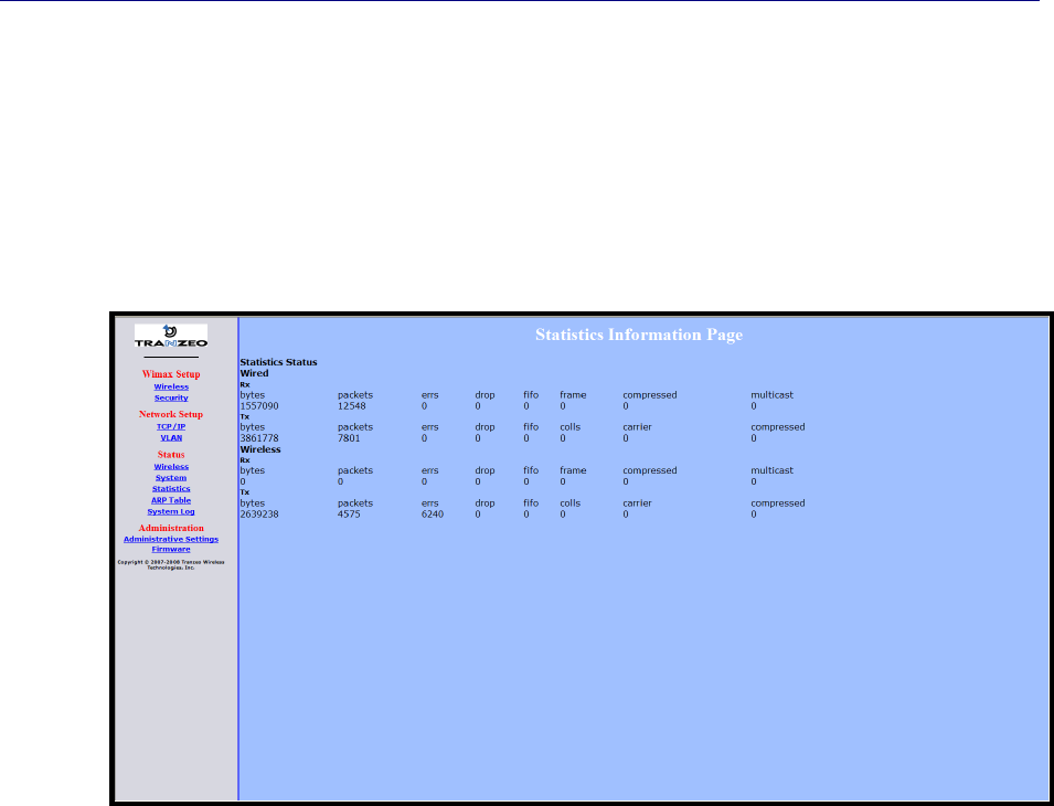
3.4 Statistics Information Page
The Statistics Information page shows statistics of the wired and wireless packets sent
and received by the TR-WMX-3.5. Figure 3-4 shows this page and Table 3-4 describes the
fields on it.
Figure 3-4. Statistics Information Page

Statistics Information Page
TR-WMX-3.5 Subscriber Unit User's Guide
39
Table 3-4. Statistics Information Page
Field Description
Wired Received (Rx) and transmitted (Tx) statistics for the TR-WMX-3.5’s wired interface.
• Bytes – number of bytes transmitted (Tx) or received (Rx) by the TR-WMX-3.5 on the wired
network.
• Packets – number of packets transmitted (Tx) or received (Rx) the TR-WMX-3.5 on the wired
network.
• Errs – number of transmit/receive errors detected by the TR-WMX-3.5 on the wired network.
• Drop – number of dropped transmitted (Tx) or received (Rx) packets detected by the TR-
WMX-3.5 on the wired network.
• Fifo – number of transmitted (Tx) or received (Rx) packets first in/first out between the TR-
WMX-3.5 and the wired network.
• Frame – number of frames transmitted (Tx) or received (Rx) by the TR-WMX-3.5 on the wired
network.
• Compressed – number of compressed frames transmitted (Tx) or received (Rx) by the TR-
WMX-3.5 on the wired network
• Muilticast – number of multicast frames transmitted (Tx) or received (Rx) by the TR-WMX-3.5
on the wired network
Wireless Received (Rx) and transmitted (Tx) statistics for the TR-WMX-3.5’s wireless interface.
• Bytes – number of bytes transmitted (Tx) or received (Rx) by the TR-WMX-3.5 on the wireless
network.
• Packets – number of packets transmitted (Tx) or received (Rx) the TR-WMX-3.5 on the
wireless network.
• Errs – number of transmit/receive errors detected by the TR-WMX-3.5 on the wireless
network.
• Drop – number of dropped transmitted (Tx) or received (Rx) packets detected by the TR-
WMX-3.5 on the wireless network.
• Fifo – number of transmitted (Tx) or received (Rx) packets first in/first out between the TR-
WMX-3.5 and the wireless network.
• Frame – number of frames transmitted (Tx) or received (Rx) by the TR-WMX-3.5 on the
wireless network.
• Compressed – number of compressed frames transmitted (Tx) or received (Rx) by the TR-
WMX-3.5 on the wireless network
• Muilticast – number of multicast frames transmitted (Tx) or received (Rx) by the TR-WMX-3.5
on the wireless network

Chapter 3, Viewing Status Information
40 TR-WMX-3.5 Subscriber Unit User's Guide
3.5 ARP Information Page
The TR-WMX-3.5 has an Address Resolution Protocol (ARP) table that automatically maps
the TR-WMX-3.5 IP address to the MAC address of a switch. The ARP Information page
shows the TR-WMX-3.5 IP address and the corresponding MAC address of the switch. For
example, the page in Figure 3-5 shows that the TR-WMX-3.5’s IP address is
72.166.143.1, which corresponds to the MAC address 00:A0:C8:2B:2A:4A.
Figure 3-5. ARP Information Page
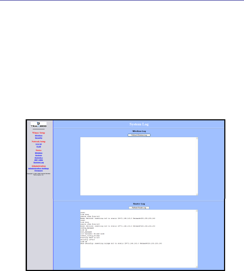
System Log
TR-WMX-3.5 Subscriber Unit User's Guide
41
3.6 System Log
The TR-WMX-3.5 has separate logs that contain information about the unit’s wireless
and router operations. Using the System Information page, you can view the information
in these logs.
The Wireless Log area shows wireless information recorded in the wireless log.
The Router Log area shows router information recorded in the router log.
Both areas have a Refresh button that can be used to update the information displayed
in the respective areas on this page.
Figure 3-6 shows this page.
Figure 3-6. System Log Page

Chapter 3, Viewing Status Information
42 TR-WMX-3.5 Subscriber Unit User's Guide
This page intentionally left blank.

43
4 Configuring Administrative Settings
The Configurator has an Administration link that lets you perform a variety of
administrative tasks, such as:
Restoring the TR-WMX-3.5 to its factory defaults
Rebooting the TR-WMX-3.5 without returning the unit to its factory default settings.
Changing the device name and location.
Enabling or disabling Web, SSH, and Telnet access.
Enabling or disabling the TR-WMX-3.5 status LEDs.
Changing the user name and password required to log in to the Configurator.
The topics covered in this chapter are:
Section 4.1, Displaying the Administrative Settings Page (page 44)
Section 4.2, Returning to Factory Default (page 44)
Section 4.3, Rebooting the TR-WMX-3.5 Unit (page 45)
Section 4.4, Changing Device Configuration Settings (page 45)
4
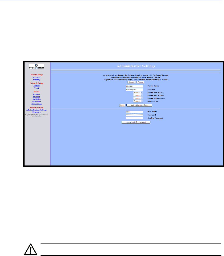
Chapter 4, Configuring Administrative Settings
44 TR-WMX-3.5 Subscriber Unit User's Guide
4.1 Displaying the Administrative Settings Page
All administrative tasks are performed from the Administrative Settings page. To display
the Administrative Settings page, click the Administrative Settings link under
Administration in the navigation panel of the Configurator. Figure 4-1 shows the
Administrative Settings page.
Figure 4-1. Administrative Settings Page
4.2 Returning to Factory Default Settings
Using the Defaults button on the Administrative Settings page, you can return the TR-
WMX-3.5 to the settings that were in effect when you powered it up for the first time.
When you click this button, a precautionary message tells you that proceeding will
remove any custom settings you set and return all parameters to their factory default
settings. You can then click OK to continue or Cancel to cancel the operation.
For a complete list of the TR-WMX-3.5’s default settings, see Appendix A.

Rebooting the TR-WMX-3.5 Unit
TR-WMX-3.5 Subscriber Unit User's Guide
45
4.3 Rebooting the TR-WMX-3.5 Unit
The Reboot button on the Administrative Settings page provides one way to reboot the
TR-WMX-3.5 (the other way is using the Apply and Reboot button described in section
2.1). If you change any TR-WMX-3.5 configuration settings, you must use one of these
methods to reboot the TR-WMX-3.5 and put the settings into effect.
When you click this button, a precautionary message tells you that proceeding will
reboot the TR-WMX-3.5. You can then click OK to continue or Cancel to cancel the
operation.
Rebooting disconnects the TR-WMX-3.5 and any connections currently running.
It may take up to 60 seconds before the TR-WMX-3.5 is running and accessible
again. When you reboot the TR-WMX-3.5, the Status LED flashes while the
unit reboots and goes ON when the unit completes the reboot process.
4.4 Changing Device Configuration Settings
Using the Administrative Settings page, you can:
Change the TR-WMX-3.5 device name and location
Enable or disable Web, SSH, and Telnet access
Enable or disable the TR-WMX-3.5 LEDs
4.4.1 Changing the Device Name and Location
The TR-WMX-3.5 device name is the name used to identify the device. The device name
appears on the Information Page (see section 3.1). If your installation has a number of
devices, you will probably want to assign a unique device name to each TR-WMX-3.5.
To change the device name:
1. On the Administrative Settings page, delete the current name shown in the Device
Name field and enter a new name.
2. To change the location, delete the current location shown in the Location field and
enter a new location.
3. Click the Apply button to save your changes. When the next page appears, either:
– Click the Reboot button to reboot the TR-WMX-3.5 and apply the settings.
– Change settings on other pages, then reboot the TR-WMX-3.5 to apply all the
new settings.

Chapter 4, Configuring Administrative Settings
46 TR-WMX-3.5 Subscriber Unit User's Guide
4.4.2 Enabling or Disabling Web, SSH, and Telnet Access
Using the Administrative Settings page, you can enable or disable Web access, SSH
access, and Telnet access to the TR-WMX-3.5.
If you disable Web access, you will not be able to access the TR-WMX-3.5 using a browser.
If you disable SSH access, you will not be able to access the TR-WMX-3.5 via an SSH
session.
If you disable Telnet access, you will not be able to access the TR-WMX-3.5 using a
Telnet session.
To enable or disable Web, SSH, and Telnet access to the TR-WMX-3.5, use the following
procedure.
1. To enable or disable Web access to the TR-WMX-3.5, click the down arrow next to
Enable Web Access and select Enable or Disable from the drop-down list.
2. To enable or disable SSH access to the TR-WMX-3.5, click the down arrow next to
Enable SSH Access and select Enable or Disable from the drop-down list.
3. To enable or disable Telnet access to the TR-WMX-3.5, click the down arrow next to
Enable telnet Access and select Enable or Disable from the drop-down list.
4. Click the Apply button to save your changes. Then either:
– Click the Reboot button on the next page that appears to apply the settings and
reboot the TR-WMX-3.5 at this time.
– Change any other configuration settings you want to modify. When finished,
apply all the new and reboot the TR-WMX-3.5.
4.4.3 Enabling or Disabling the Status LEDs
Using the Administrative Settings page, you can enable or disable the 10 status LEDs on
the rear panel of the TR-WMX-3.5. By default, the LEDs are configured to be ON. This
means they show the status of the TR-WMX-3.5 as described in Table 1-4 on page 16. If
the TR-WMX-3.5 will be installed in a location where the LEDs cannot be observed, you
can disable them and rely on the status screens described in Chapter 3 to assess the
status of the TR-WMX-3.5.
To enable or disable the status LEDs on the TR-WMX-3.5, use the following procedure.
1. Click the down arrow next to Status LEDs and select Enable or Disable from the
drop-down list.
2. Click the Apply button to save your changes. Then either:
– Click the Reboot button on the next page that appears to apply the settings and
reboot the TR-WMX-3.5 at this time.
– Change any other configuration settings you want to modify. When finished,
apply all the new and reboot the TR-WMX-3.5.

Changing Device Configuration Settings
TR-WMX-3.5 Subscriber Unit User's Guide
47
4.4.4 Changing Log In Settings
Using the Administrative Settings page, you can change the user name and password
used to log in to the Configurator. For security purposes, we recommend you change the
default password.
1. To change the user name, click in the User Name field, delete the name shown, and
enter a new user name.
2. To change the log in password, click in the Password field, delete the entry, and
enter a new password.
3. Click in the Confirm Password field, delete the entry, and enter the same password
you typed in step 2.
For security, every typed password character appears as a bullet (•).
5. Click the Apply button to save your changes. When the next page appears, either:
– Click the Reboot button to reboot the TR-WMX-3.5 and apply the settings.
– Change settings on other pages, then reboot the TR-WMX-3.5 to apply all the
new settings.

Chapter 4, Configuring Administrative Settings
48 TR-WMX-3.5 Subscriber Unit User's Guide
This page intentionally left blank.

49
A Factory Default Configuration Settings
This appendix lists the factory default configuration settings that are in effect when you
unpack the TR-WMX-3.5 or reset it to factory default settings.
A.1 Default Wireless Settings
Setting Default Setting Default
Channel Bandwidth (MHz) 3.5 QoS Max Downlink SF 8
RF Profiles TDD QoS Max Uplink SF 8
CP Size 1/16 AFS channel bandwidth (in
MHz) scan order
35-7-0
Secondary Management
Connection Support
Secondary Management
(Default)
For Least Robust DIUC as
LSB/MSB and DCD CCC as
MSB/LSB
Enable
Initial Ranging Burst Inverting Software Auto MAC Message Strict
Checking
Disable
Adaptive Modulation (DBPC) Auto using CINR thresholds Pack Enable For Primary
CID
Enable
Frequency (KHz) 3650000 Fragment Enable For
Primary CID
Enable
Initial Delay Correction Value 0 TX overrun fix Disable
Max TX Power (dBm) 20 QoS Admitted Bit Disable
Min TX Power (dBm) -10 QoS Tx Policy Checking Disable
RX Antenna Gain (1/4dB
step)
0 Enable 0 symbol HFDD
Patch
Disable
TX Antenna Gain (1/4dB
step)
0 AFS mode Disable
MRTR for SMC in bps 100000 CS classifier rules' type
check bypass
Disable
Lost DL/UL MAP Interval 700
A

Appendix A, Factory Default Configuration Settings
50 TR-WMX-3.5 Subscriber Unit User's Guide
A.2 Default Security Settings
Setting Default
Encryption Support Disable
A.3 Default TCP/IP Settings
Setting Default
IP Mode
DHCP Client Enabled
A.4 Default VLAN Settings
Setting Default
VLAN Mode Disable
VLAN Tag Allow (Allow All Traffic Through)
Nested VLANs Disable
Management VLAN ID 0
Valid VLAN ID Range 0
Vlan Default ID = 0, Priority = 0
A.5 Default Administrative Settings
Setting Default
Device Name TR-WMX
Location San Diego, Ca
Enable Web Access Enabled
Enable SSH Access Disabled
Enable Telnet Access Disabled
Status LEDs Enabled
User Name Admin
Password Default
Confirm Password default
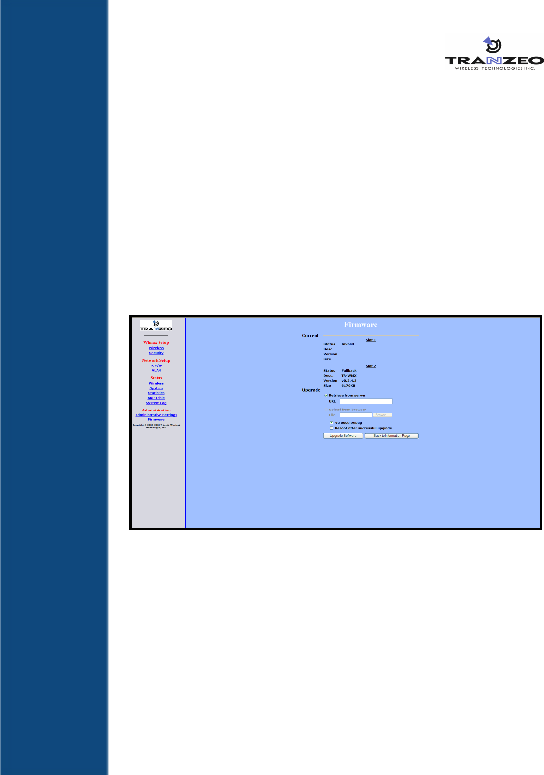
51
B Upgrading Firmware
From time to time, Tranzeo Wireless Technologies, Inc. makes new firmware available
for the TR-WMX-3.5. The firmware may add new features to the TR-WMX-3.5 and/or fix
problems.
This appendix describes how to upgrade the firmware for the TR-WMX-3.5.
1. Log in to the Configurator (see section 1.5.1).
2. In the left pane, under Administration, click Firmware. The Firmware page appears
(see Figure B-1). The Current section shows information about the current firmware
installed. The Upgrade section is where you specify the new firmware you want to
install. :f
Figure B-1. Firmware Page
3. To view the output of what is happening throughout the firmware upgrade process,
check Verbose Debug.
4. To reboot the TR-WMX-3.5 after its firmware has been upgraded, check Reboot
after successful upgrade.
5. Under Upgrade, select retrieve from server (if it is not already selected).
6. In the URL field, enter the Uniform Resource Locator (URL) of the FTP server where
the new firmware file is located.
7. Log in to the server and download the firmware file.
B

Appendix B, Upgrading Firmware
52 TR-WMX-3.5 Subscriber Unit User's Guide
8. After the firmware file has been downloaded, upload it to the TR-WMX-3.5 using
your browser. Under Upload from browser, click the Browse, select the firmware
file, and click OK.
9. Click Upgrade Software to start the upgrade procedure. If you checked Reboot
after successful upgrade, the TR-WMX-3.5 reboots automatically following the
firmware upgrade; otherwise, you must manually reboot the TR-WMX-3.5 to have
the new firmware upgrade take effect.

53
C Technical Support
Technical support is available by phone, live chat, email, and fax.
C.1 Telephone Support
In-house telephone support is available during the hours and at the telephone numbers
shown in Table C-1. Voice mail is available during non-telephone hours.
Table C-1. Telephone Support Hours and Numbers
Location Telephone Hours Telephone Number
Americas 1:00 AM to 5:00 PM PST +1 888 460 6366
(Toll free USA and Canada)
Europe, Africa, Middle East 9:00 AM to 1:00 AM GMT +353-61-775-702
Americas outside the USA and Canada +1 604 460 6366
Australia, Asia +1 604 460 6366
C.2 Live Chat
Live chat offers one-to-one chat support with a Tranzeo support representative
allows you to receive real-time answers to your questions. Live chat is available
during the hours and numbers shown in Table C-2.
Table C-2. Live Chat Support Hours
Location Live Chat Hours
Americas 1:00 AM to 5:00 PM PST
Europe, Africa, Middle East 9:00 AM to 1:00 AM GMT
C.3 Email
Technical support can be reached by email at support@tranzeo.com. RMA requests
should be addressed to rma@tranzeo.com.
C

Appendix C, Technical Support
54 TR-WMX-3.5 Subscriber Unit User's Guide
C.4 Fax
Faxes can be sent to our 24-hour fax number at +1 604 460 6005.

55 TR-WMX-3.5 Subscriber Unit User's Guide
Glossary
ARP Address Resolution Protocol, a network layer protocol used to convert an
IP address into a physical (DLC) address, such as an Ethernet address. A
host wishing to obtain a physical address broadcasts an ARP request onto
the TCP/IP network. The host on the network that has the IP address in
the request replies with its physical hardware address.
CINR Carrier to Interference and Noise Ratio, a measure of quality for wireless
signals.
CPE Customer Premises Equipment, communications equipment that resides
on the customer's premises and is owned or leased by the customer.
Gateway A node on a network that serves as an entrance to another network.
IEEE Institute of Electrical and Electronics Engineers (pronounced I-triple-E),
an organization that develops standards for the computer, networking,
and electronics industries.
MAC Address Media Access Control address, a hardware address that uniquely
identifies each node of a network.
PKM Privacy key management, a protocol used to authenticate nodes on the
network, and distribute and maintain private keys used for traffic
encryption.
PoE Power over Ethernet, a solution where electrical current is run to
networking hardware over an Ethernet Category 5 or higher data cable.
No additional AC power cord is needed, minimizing the amount of cables
needed and the hassle of installing extra outlets.
RSA Rivest, Shamir, and Adelman, a public-key encryption technology that
requires an extraordinary amount of computer processing power and
time to break. The RSA algorithm has become the de facto standard for
industrial-strength encryption, especially for data sent over the Internet.
RSSI Received Signal Strength Indicator, a circuit or signal that indicates the
strength of an incoming signal into a receiver, such as your TR-WMX-3.5.
SNR Signal-to-Noise Ratio, the ratio of the amplitude of a desired analog or
digital data signal to the amplitude of noise in a transmission channel at
a specific point in time.

Glossary
56 TR-WMX-3.5 Subscriber Unit User's Guide
SSH Secure Shell, a program to log into another computer over a network to
execute commands in a remote machine, and to move files from one
machine to another. SSH provides strong authentication and secure
communications over insecure channels, protecting a network from
attacks such as IP spoofing, IP source routing, and DNS spoofing.
Subnet mask A mask used to determine the subnet to which an IP address belongs.
Subscriber
station
A fixed station used by a subscriber for communication within a central
office station.
Telnet A terminal emulation program for TCP/IP networks that runs on your
computer and connects your PC to a device (such as your TR-WMX-3.5
unit. You can then enter commands through the Telnet program and they
will be executed at the TR-WMX-3.5 unit.
URL Uniform Resource Locator, the global address of documents and other
resources on the World Wide Web. www.tranzeo.com is an example of a
URL.
VLAN Virtual Local Area Network, a network of computers that behave as if
they are connected to the same wire even though they may actually be
physically located on different segments of a LAN. With VLANs, a
computer can physically move to another location while remaining on the
same VLAN, without any hardware reconfiguration.

57 TR-WMX-3.5 Subscriber Unit User's Guide
Compliance Information
This device has been tested and found to comply with the limits for a Class B digital
device pursuant to Part 15 and Part 90 of the FCC rules, and Industry Canada RSS-192.
Operation is subject to the following condition: (1) this device may not cause
Interference.
To reduce potential radio interference to other users, the antenna type and its gain
should be so chosen that the equivalent isotropically radiated power (e.i.r.p.) is not
more than that permitted for successful communication.
This device must be installed so that there is a minimum of 51.5 cm between the
antenna and any person.
Declaration of Conformity
“Hereby, Tranzeo Wireless Technologies, declares that the TR-WMX-58 product family is
in compliance with the essential requirements and other relevant provisions of Directive
1999/5/EC.”
To obtain a copy of the Declaration of Conformity, contact Tranzeo Wireless
Technologies at the following:
Tranzeo Wireless Technologies Inc.
19473 Fraser Way
Pitt Meadows, BC
Canada V3Y 2V4
Geographical Restrictions
This product is intended to be used in the following geographic locations:
AT DE MT GB
BE GR NL IS
CY HU PL LI
CZ IE PT NO
DK IT SK CH
EE LV SI BG
FI LT ES RO
FR LU SE TR
Operational Restrictions
The following restrictions apply to the use of this product:
The user of this product must ensure that it complies with the EIRP limits specified by
local regulations.
Compliance Information
58 TR-WMX-3.5 Subscriber Unit User's Guide
This page intentionally left blank.

59 TR-WMX-3.5 Subscriber Unit User's Guide
Index
A
Administrative settings
displaying the Administrative Settings page, 44
Administrative Settings page, 44
Advanced configuration
network setup, 25
TCP/IP settings, 25
VLAN settings, 27
WiMAX setup, 20
security settings, 24
wireless settings, 20
ARP Page, 40
C
Changing
device name, 45
password, 47
user name, 47
Components, 3
Configurations, iii
Configurator
Administrative Settings page, 44
ARP Page, 40
changing device name, 45
changing log in settings, 47
enabling or disabling Web, SSH, and Telnet access, 46
Information Page, 32
logging in, 8
network settings, 13
pages, 18
rebooting the TR-WMX-3.5, 45
returning to factory default settings, 44
Router Log, 41
security settings, 24
Statistics Information Page, 38
System Information Page, 36
System Log, 41
TCP/IP settings, 25
VLAN settings, 27
Wireless Page, 34
wireless settings, 10, 20
Configuring the TR-WMX-3.5
administrative settings, 44
Configuring TR-WMX-3.5, 8
logging in to the Configurator, 8
network settings, 13
wireless settings, 10
Connecting the TR-WMX-3.5, 4
Contact information, vi
Conventions
safety, v
typographic, v
warning, v
D
Default administrative settings, 50
Default security settings, 50
Default settings, 49, 50
Default TCP/IP settings, 50
Default VLAN settings, 50
Default wireless settings, 49
Device name, changing, 45
E
Enabling or disabling
SSH access, 46
status LEDs, 46
Telnet access, 46
Web access, 46
F
Factory default settings
returning to, 44
Features, iv
Firmware upgrade, 51
G
Glossary, 55
I
Information Page, 32
L
LEDs
definitions, 16
enabling or disabling, 46
Log in settings, changing, 47
Logging in to the Configurator, 8
Logs, 41
M
Models, iii
Mounting the TR-WMX-3.5, 4
N
Network settings, 13
Network setup, 25
TCP/IP settings, 25
VLAN settings, 27
P
Password
Index
60 TR-WMX-3.5 Subscriber Unit User's Guide
changing, 47
entering, 8
R
Rebooting the TR-WMX-3.5, 45
Returning to factory default settings, 44
Router Log, 41
S
Safety conventions, v
Security settings, 24
SSH access, enabling or disabling, 46
Statistics Information Page, 38
Status information
status LEDs, 16
enabling or disabling, 46
using the Information Page, 15
Status LEDs, 16
enabling or disabling, 46
Status pages
ARP, 40
Information, 32
Statistics Information, 38
System Information, 36
Wireless, 34
System Information Page, 36
System Log, 41
T
TCP/IP settings, 25
Telnet access, enabling or disabling, 46
TR-WMX-3.5, 46, 49, 50
changing device name, 45
changing log in settings, 47
components, 3
configurations, iii
configuring, 8
features, iv
firmware upgrade, 51
LEDs
definitions, 16
enabling or disabling, 46
logs, 41
models, iii
mounting and connecting, 4
rebooting, 45
returning to factory default settings, 44
security settings, 24
Typographic conventions, v
U
Understanding the Configurator pages, 18
Unpacking, 3
Upgrading firmware, 51
User name
entering, 8
User name, changing, 47
User-supplied items, 3
V
VLAN settings, 27
W
Warning conventions, v
Web access, enabling or disabling, 46
WiMAX setup, 20
security settings, 24
wireless settings, 20
Wireless Page, 34
Wireless settings, 10, 20

61 TR-WMX-3.5 Subscriber Unit User's Guide