Tranzeo Wireless Technologies RAEKT2KN2 WIRELESS MESH ROUTER User Manual USERS MANUAL
Tranzeo Wireless Technologies, Inc WIRELESS MESH ROUTER USERS MANUAL
UserManual.wiki
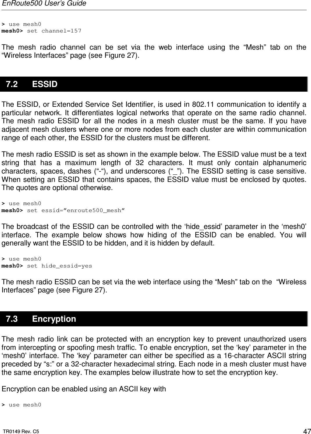
>
Tranzeo Wireless Technologies
>
RAEKT2KN2 User Manual
USERS MANUAL
Navigation menu
Upload a User Manual
Namespaces
Wiki Guide
HTML
PDF
Info
Views
User Manual
Discussion / Help
Navigation
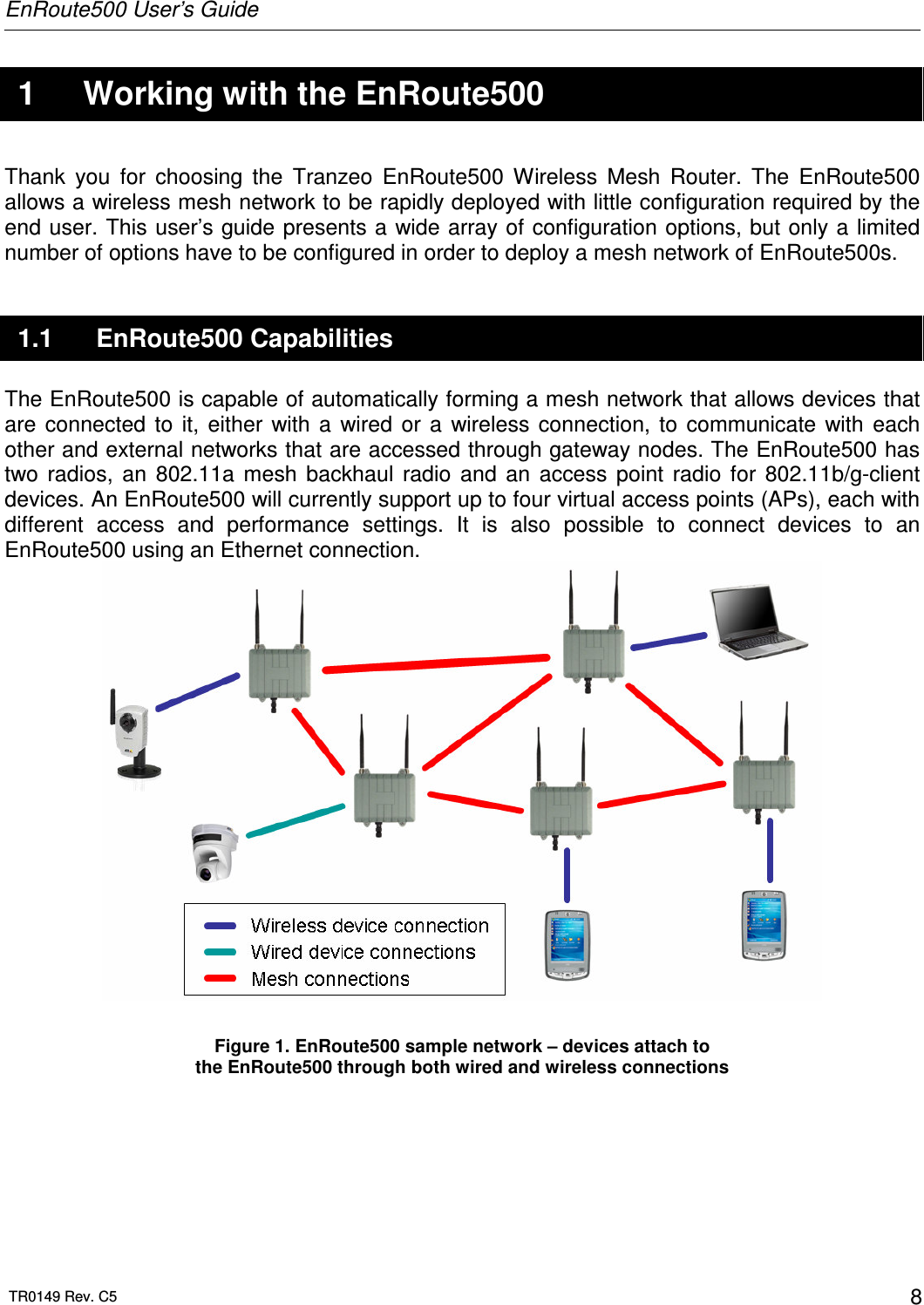
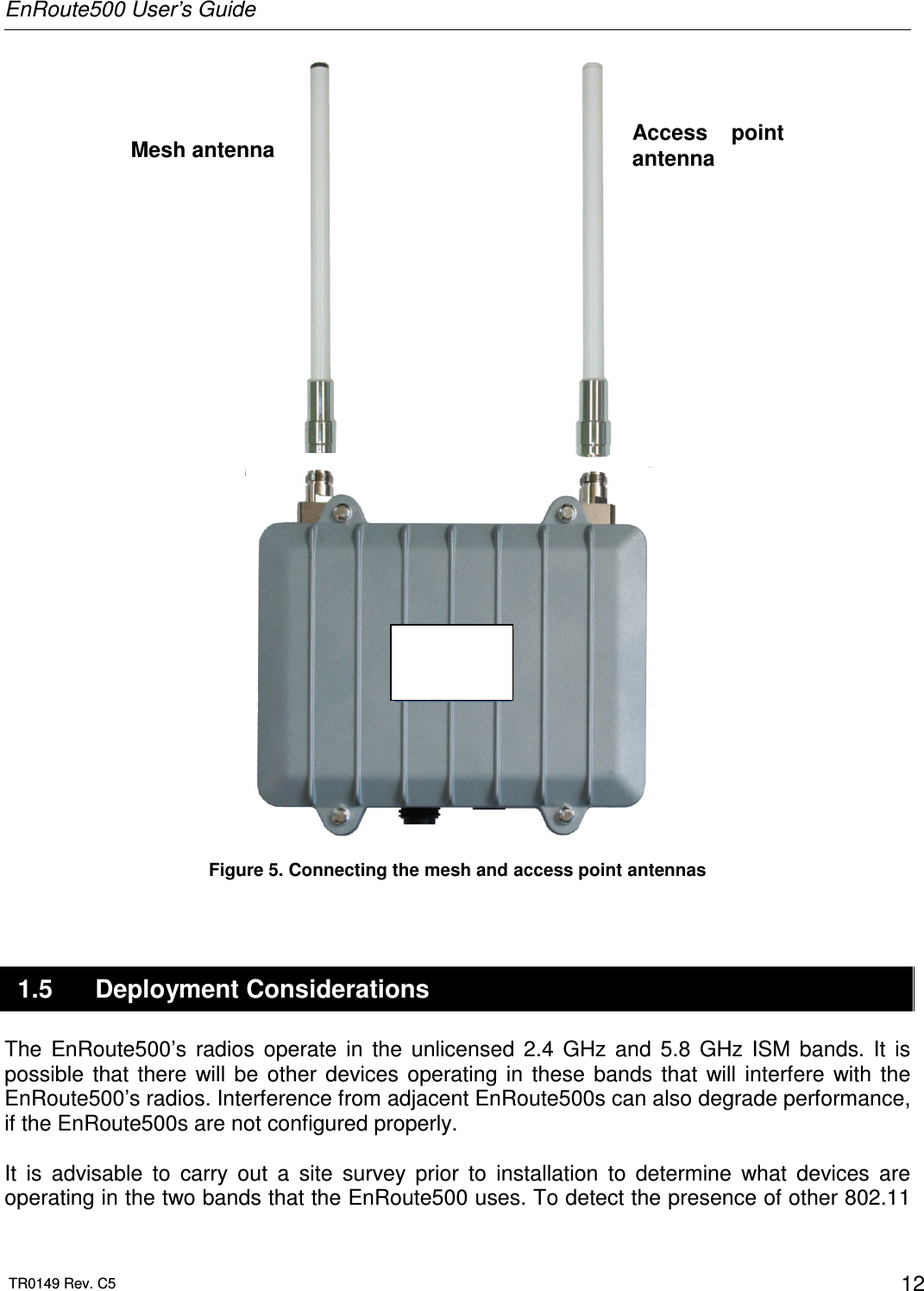
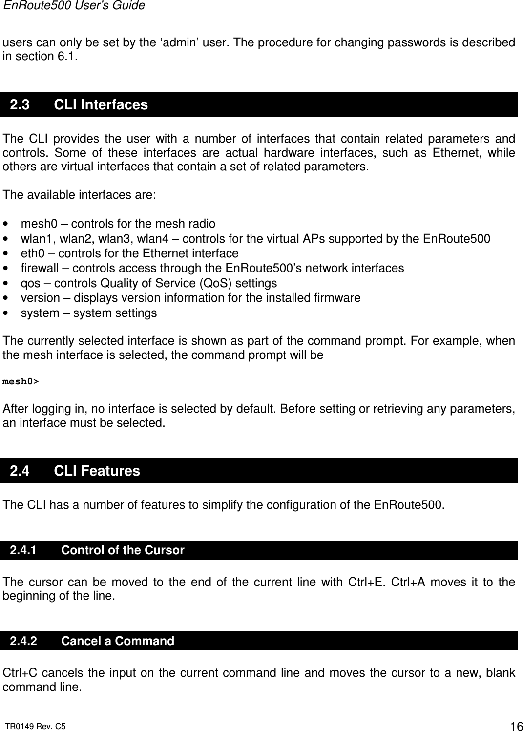
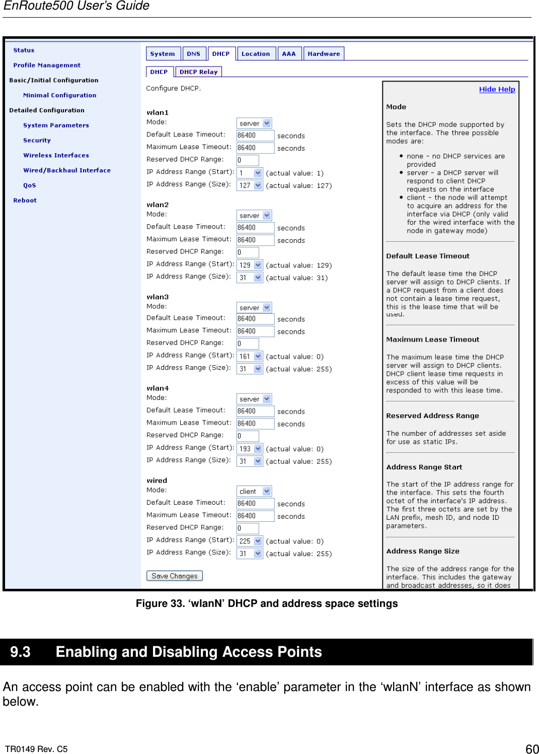
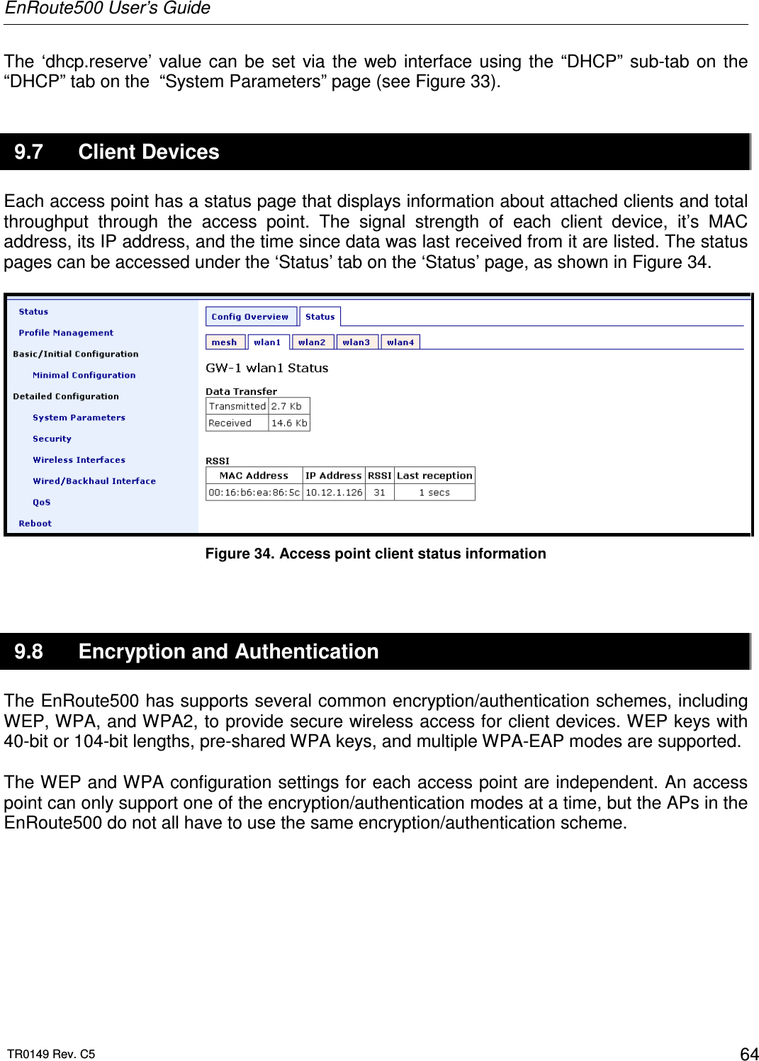
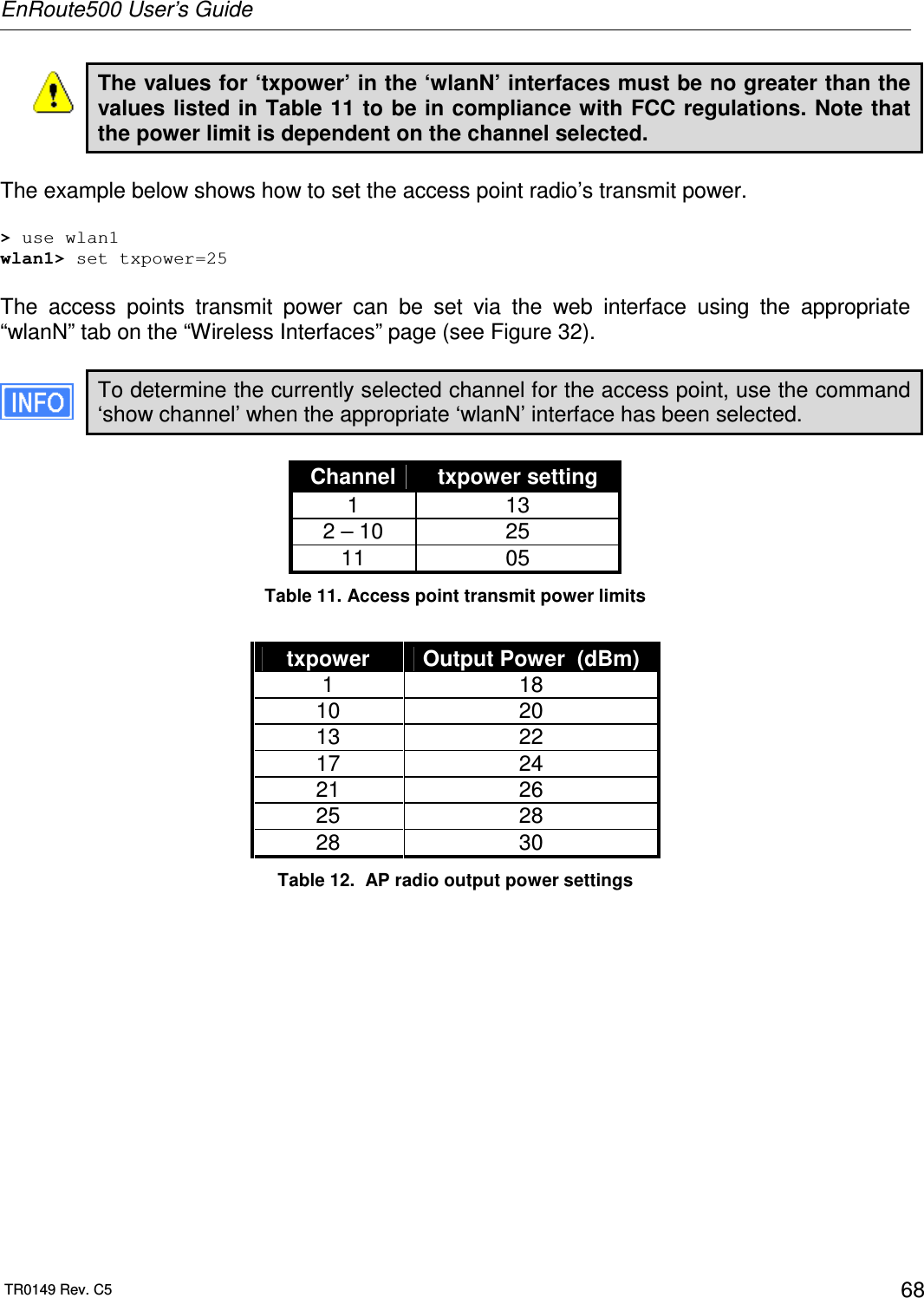
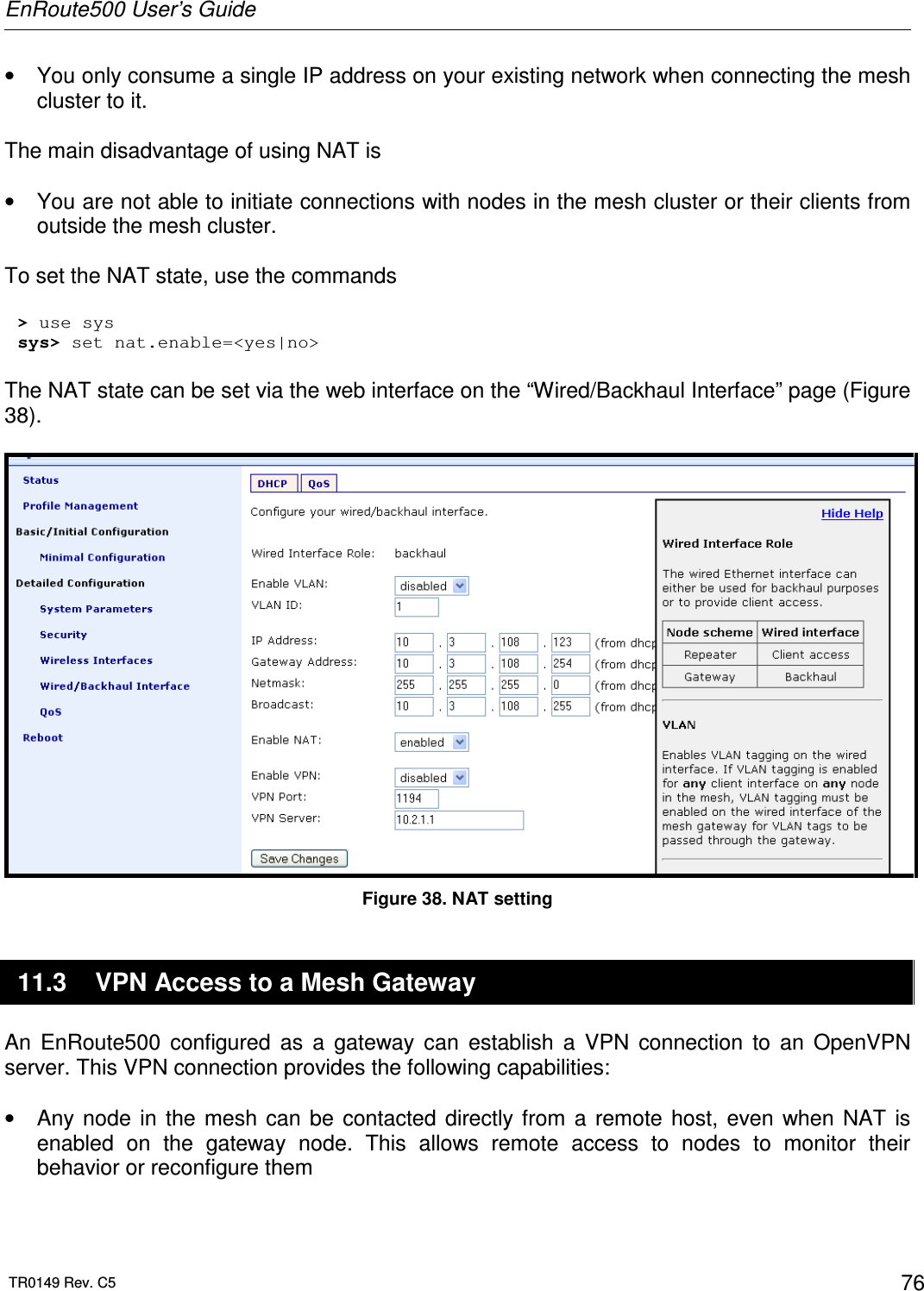
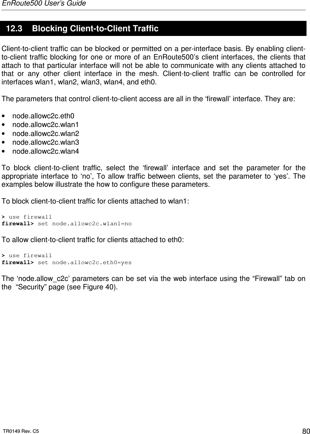
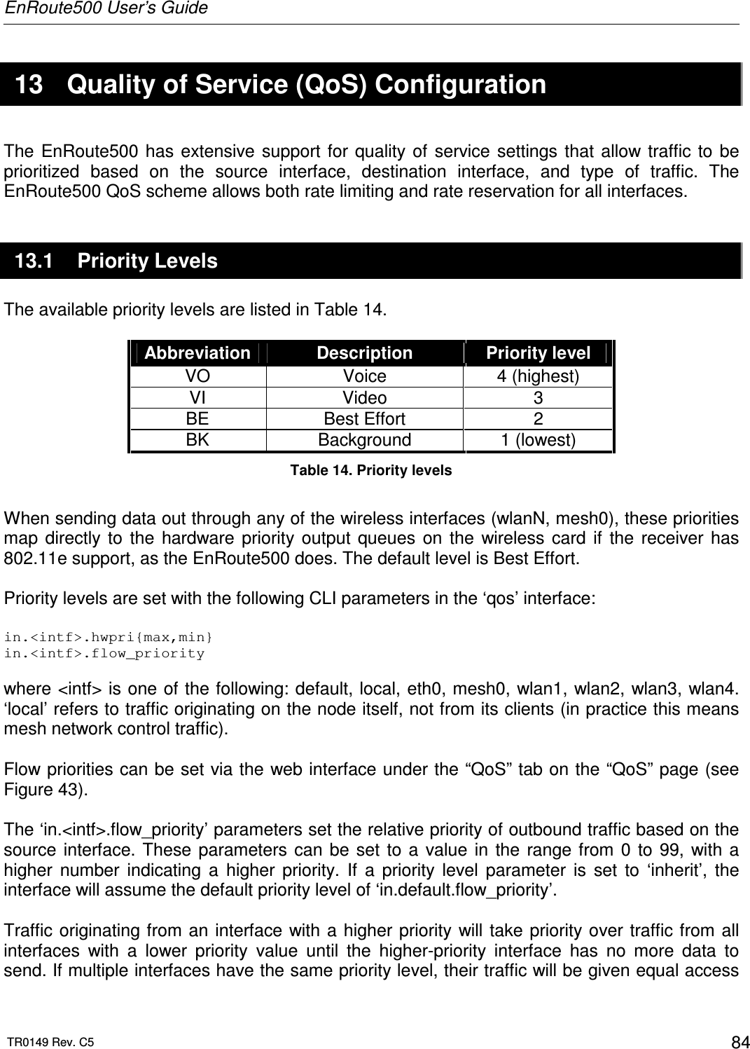
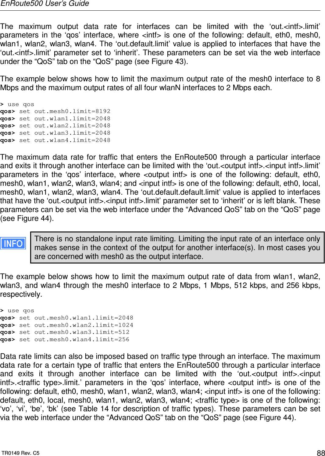
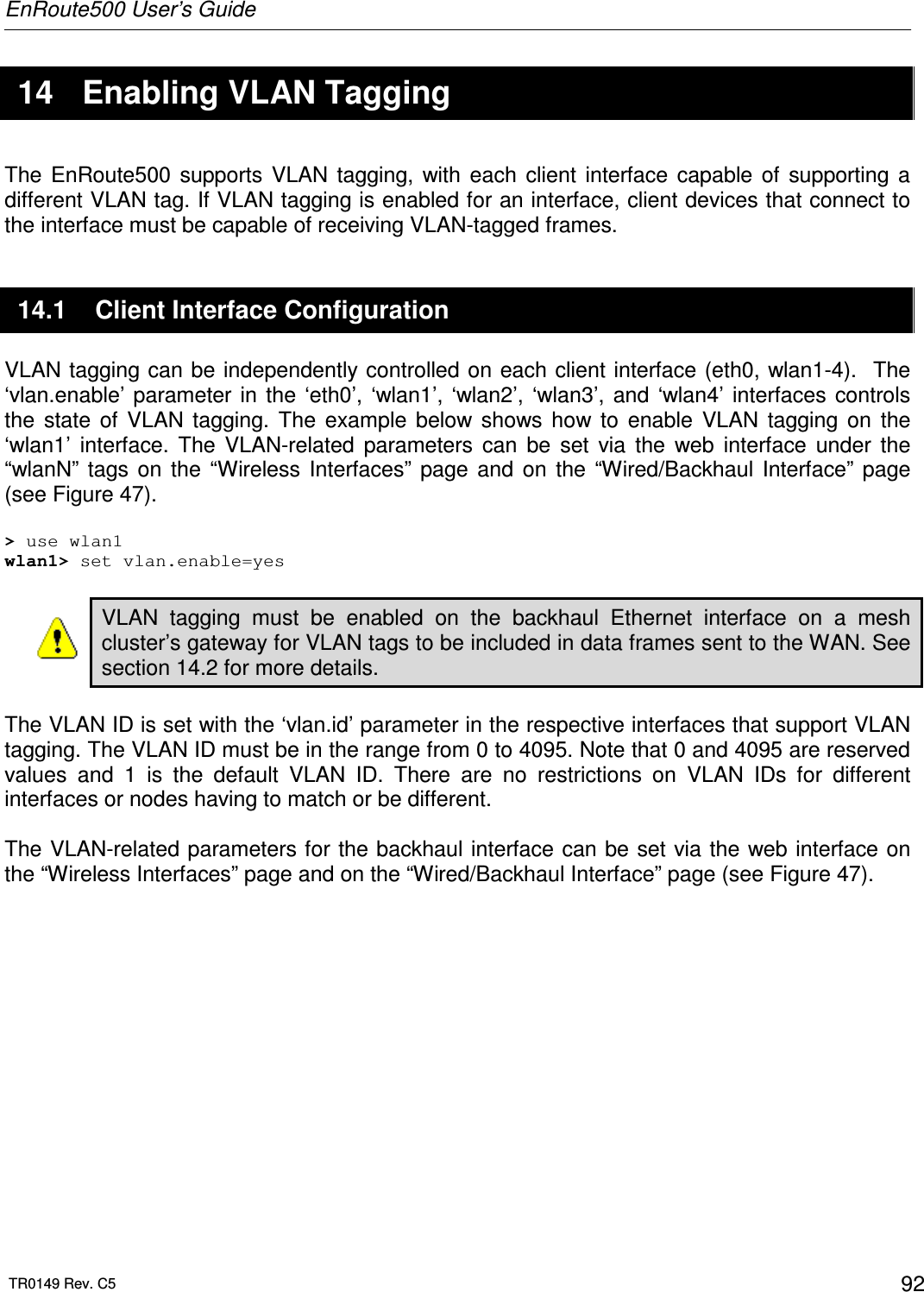
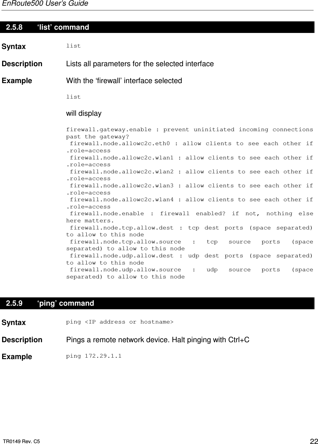
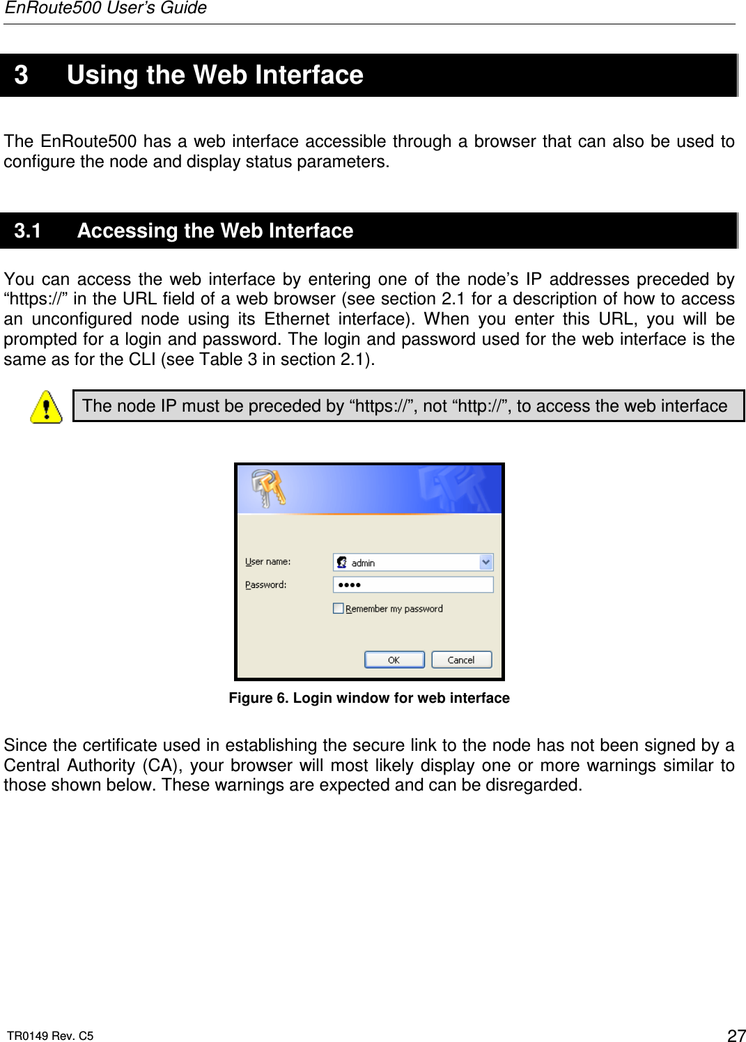
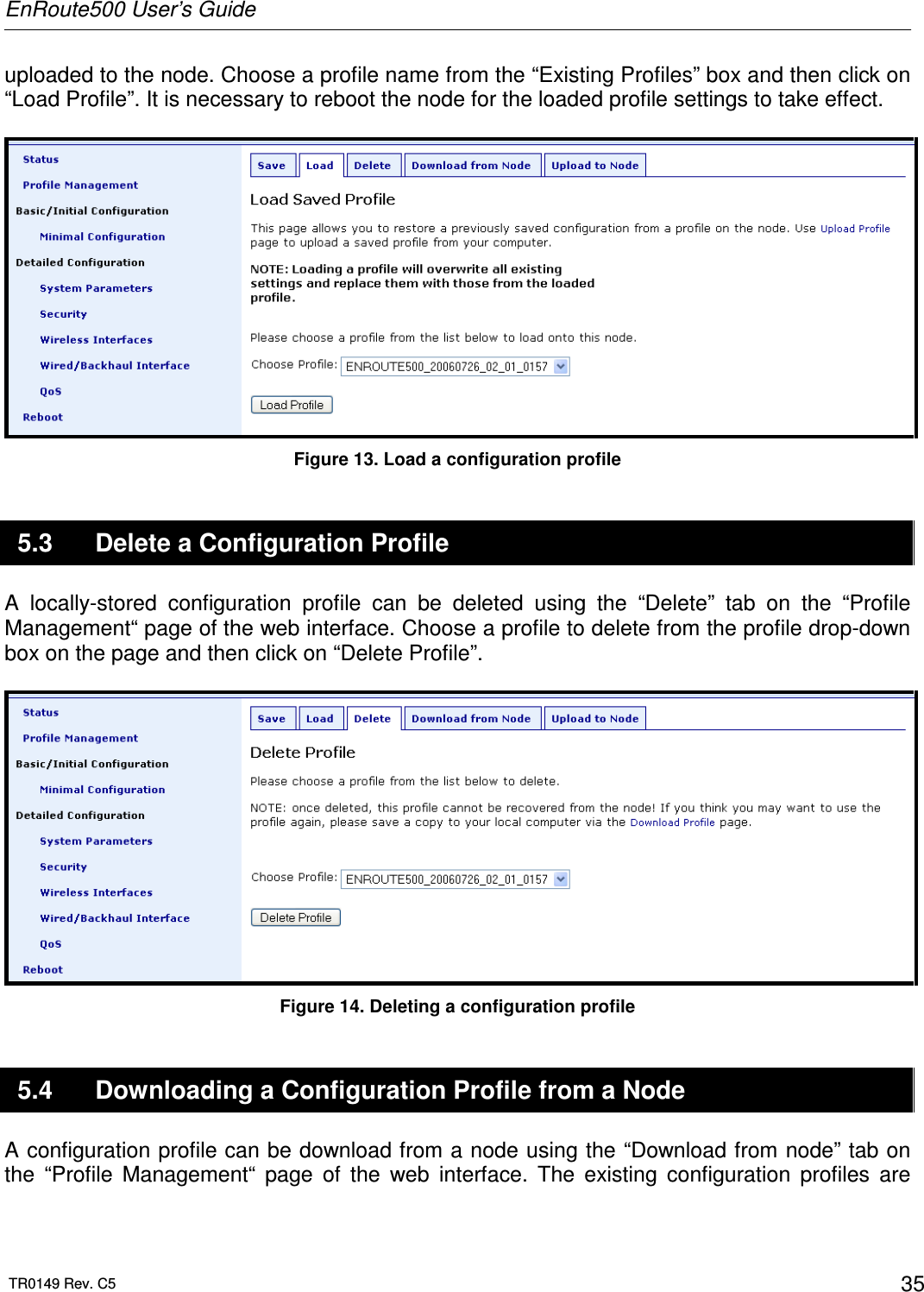
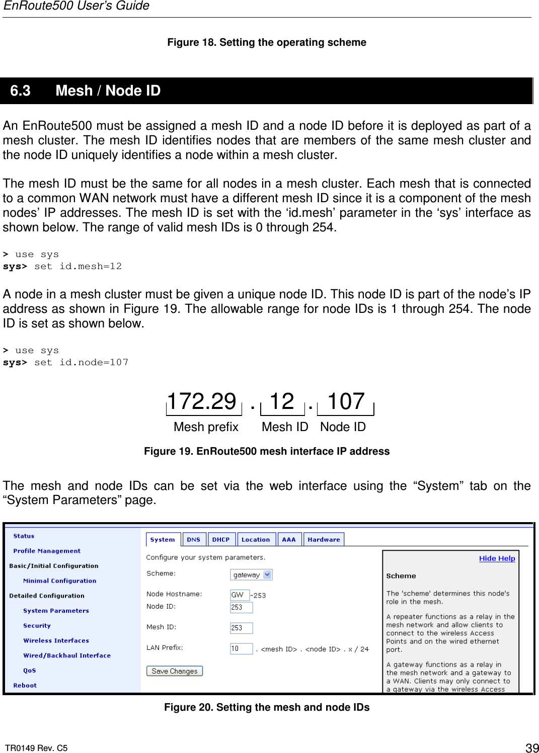
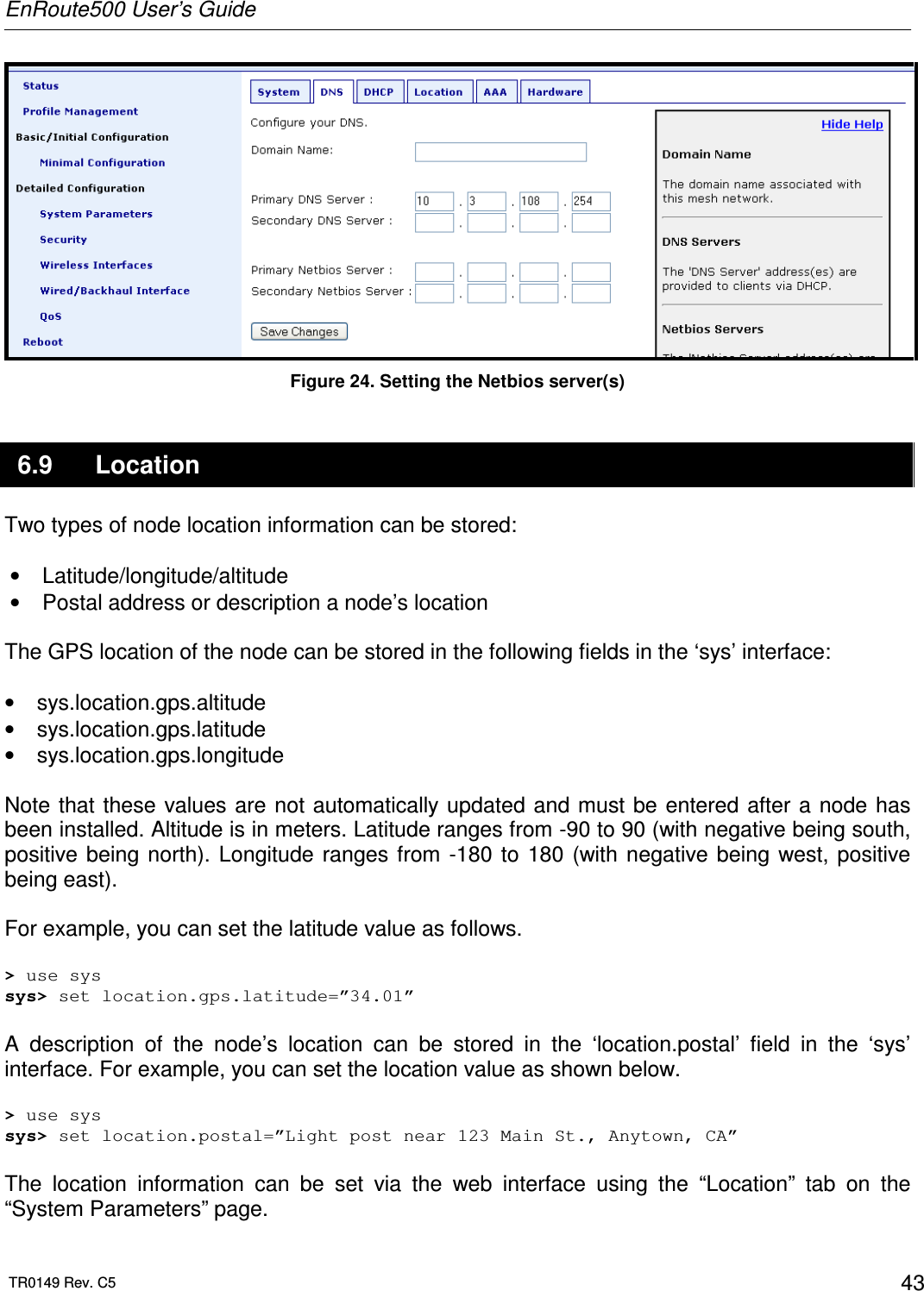
![EnRoute500 User’s Guide TR0149 Rev. C5 17 2.4.3 Searching the Command History The command history can be searched by pressing Ctrl+R and entering a search string. The most recently executed command that matches the string entered will be displayed. Press ‘Enter’ to execute that command. 2.4.4 Executing a Previous Command By using the up and down arrow keys you can select previously executed commands. When you find the command you wish to execute, you can either edit it or press ‘Return’ to execute it. 2.5 CLI Commands The usage of all CLI commands is explained below. The command syntax used is command <mandatory argument> command [optional argument] 2.5.1 ‘?’ command Syntax ? Description Pressing ‘?’ at any time in the CLI will display a help menu that provides an overview of the commands that are described in this section. It is not necessary to press ‘Enter’ after pressing ‘?’. 2.5.2 ‘whoami’ command Syntax whoami Description Displays the name of the user you are logged in as.](https://usermanual.wiki/Tranzeo-Wireless-Technologies/RAEKT2KN2/User-Guide-776051-Page-17.png)
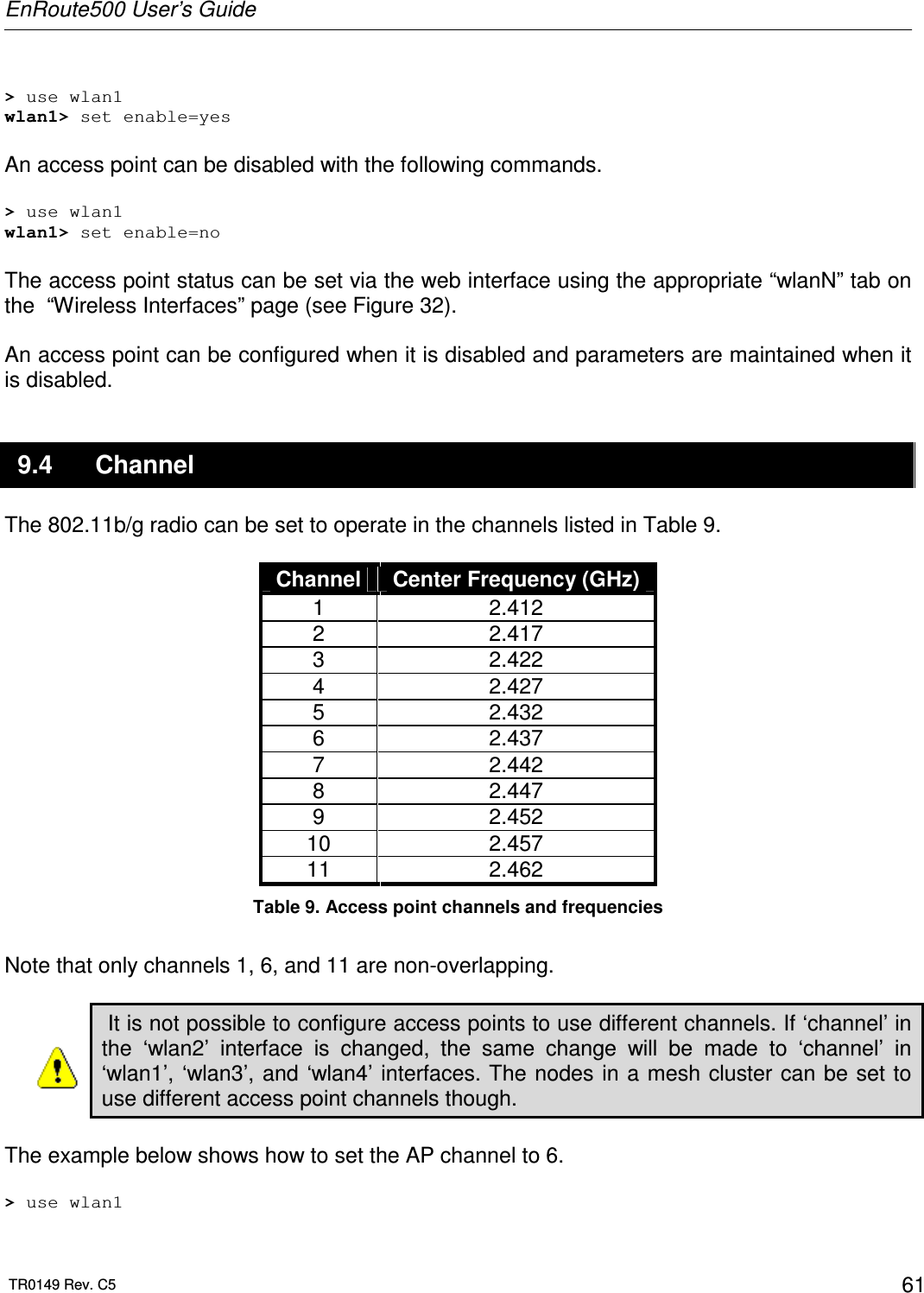
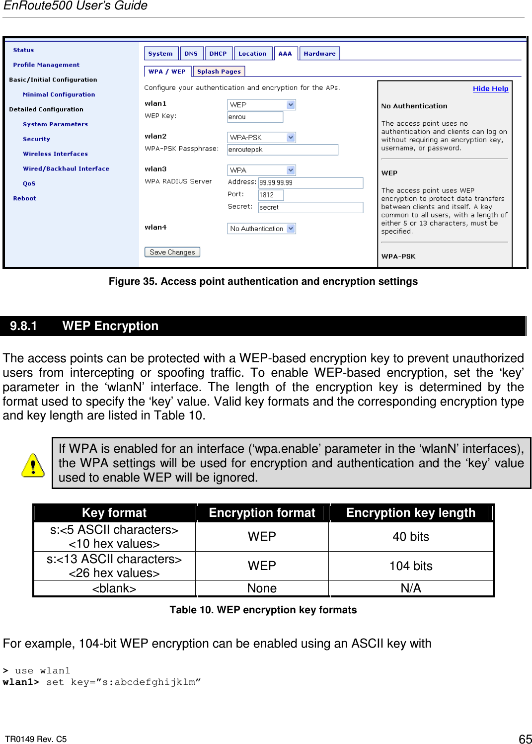
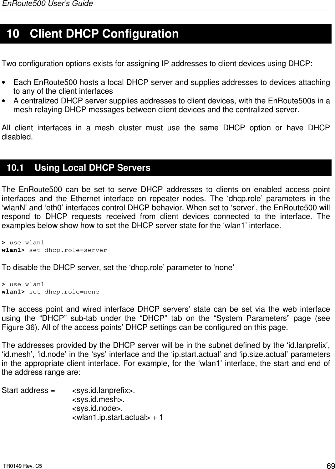
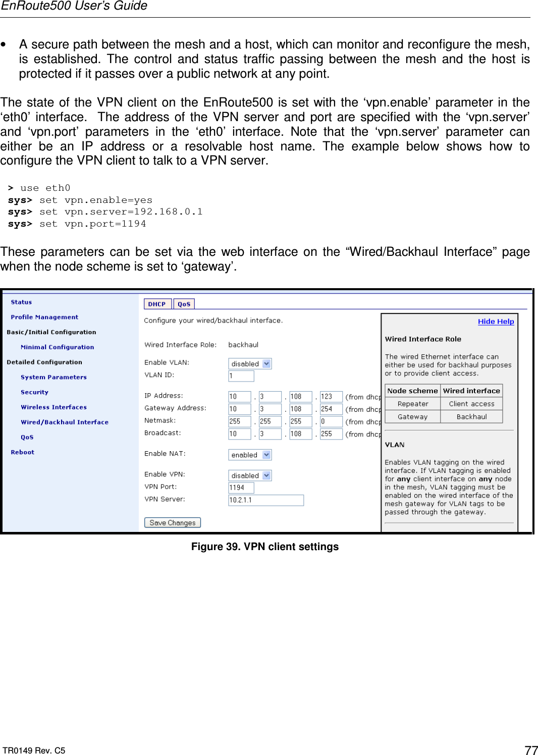
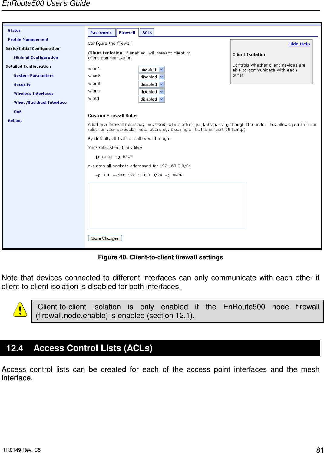
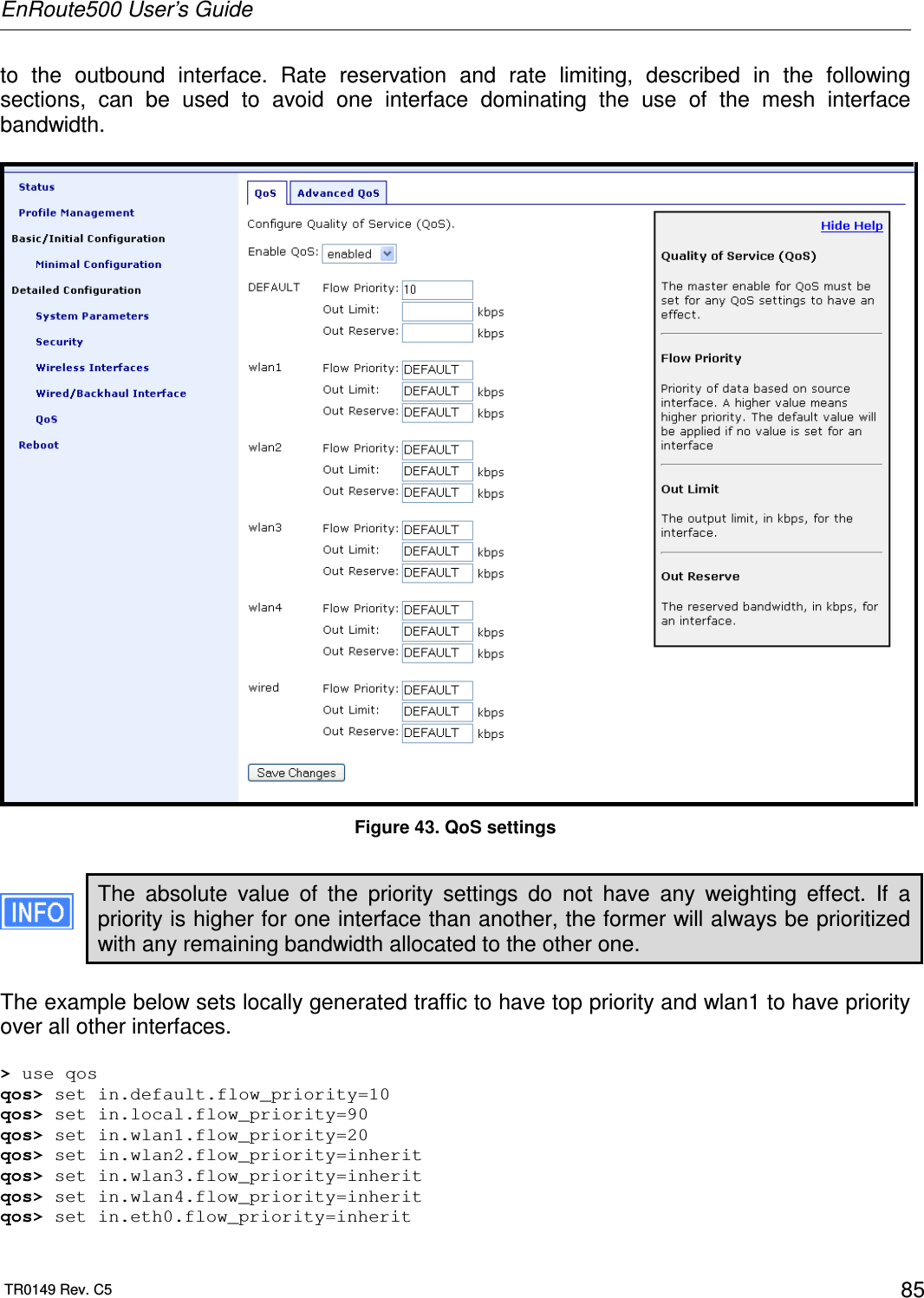
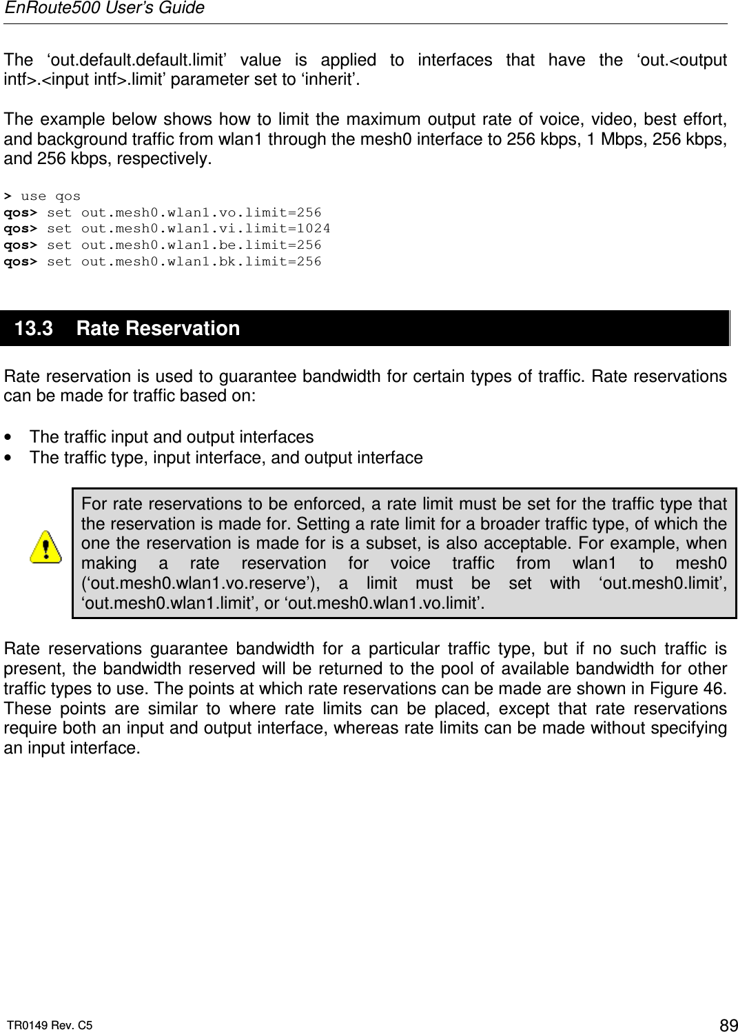
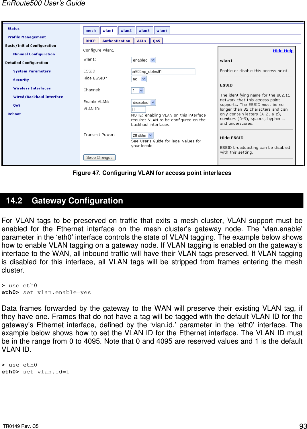
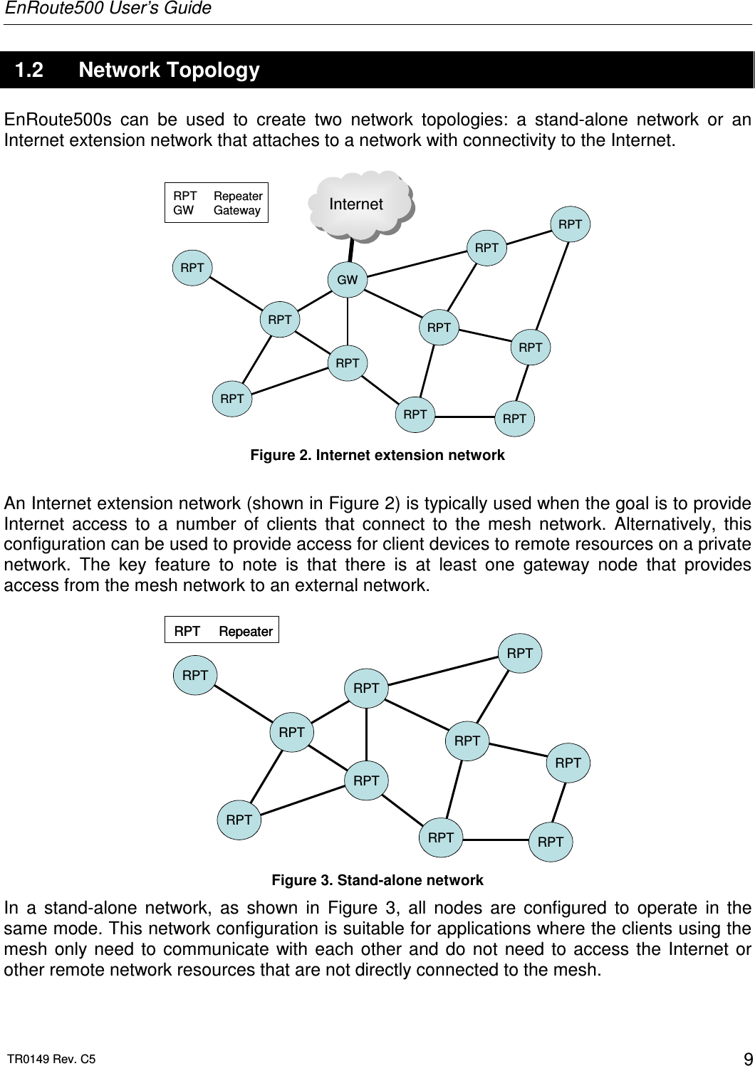
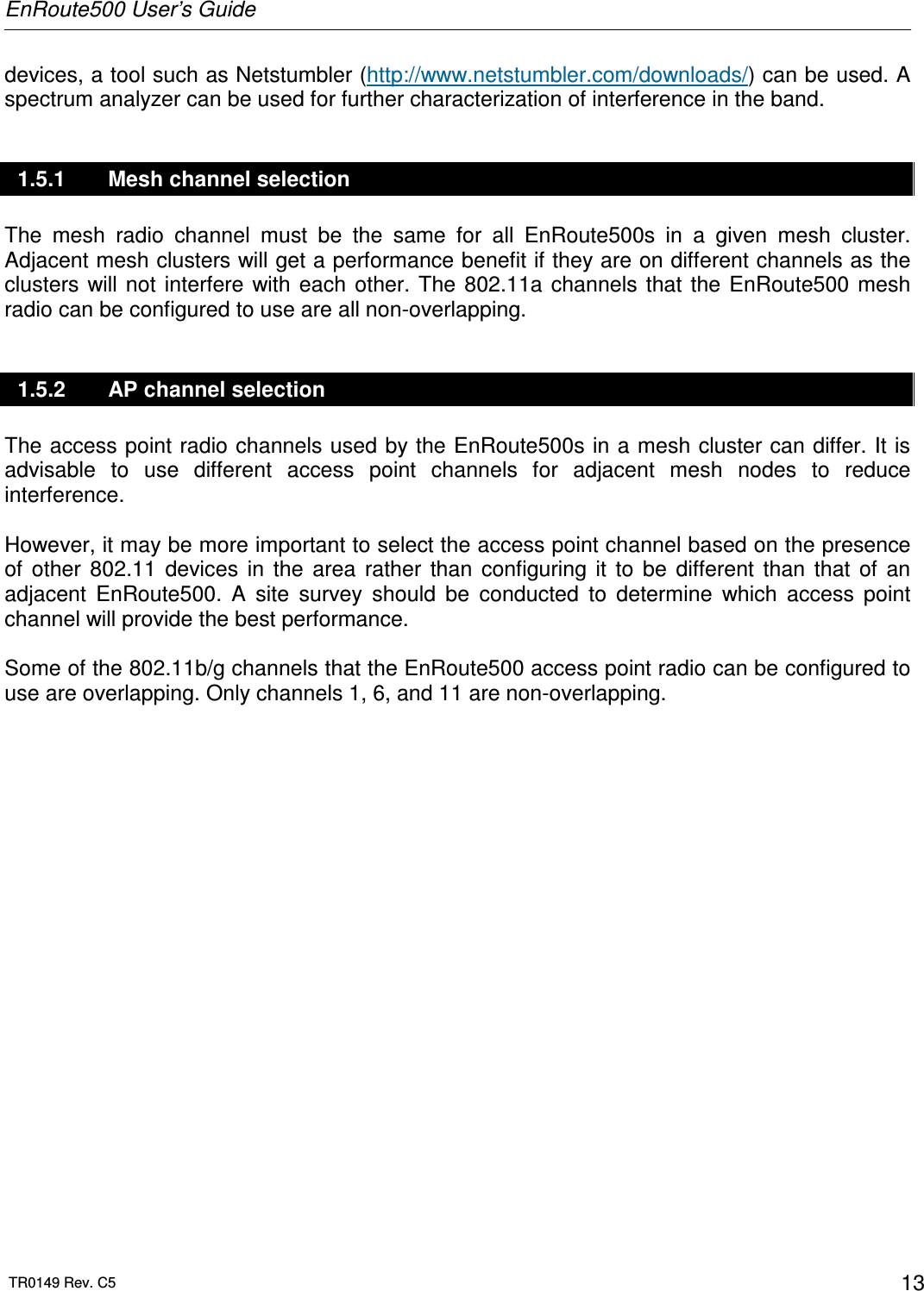
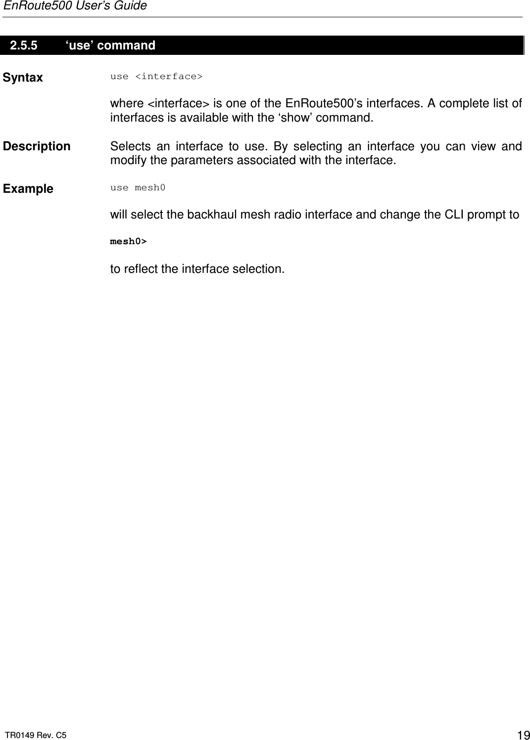
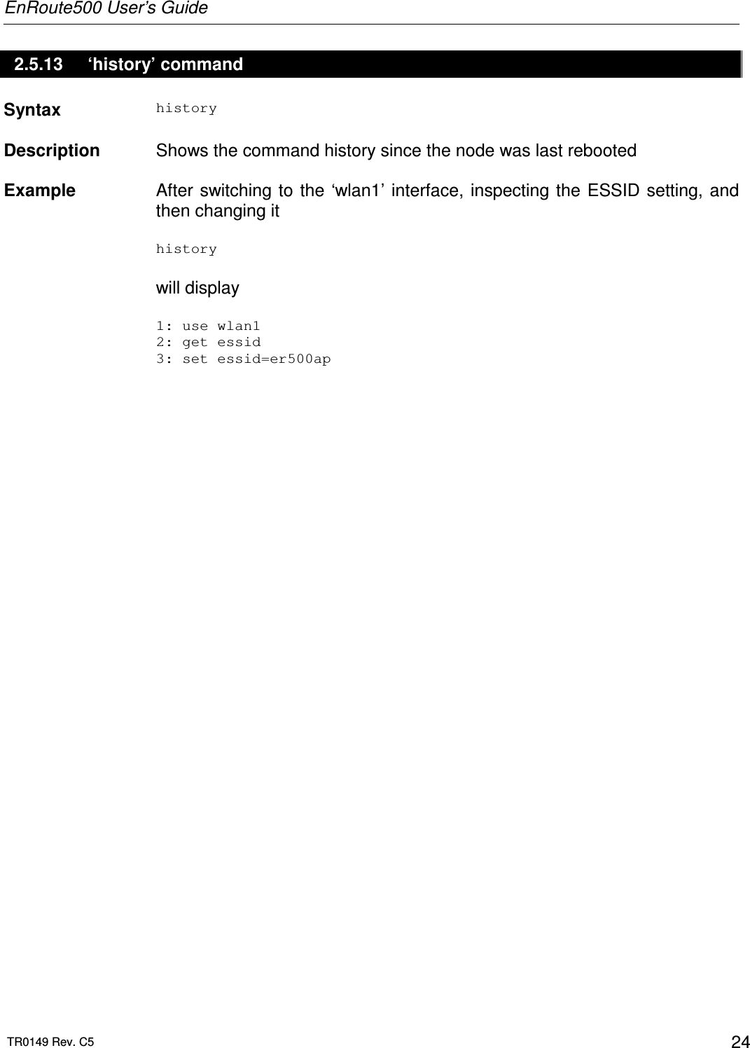
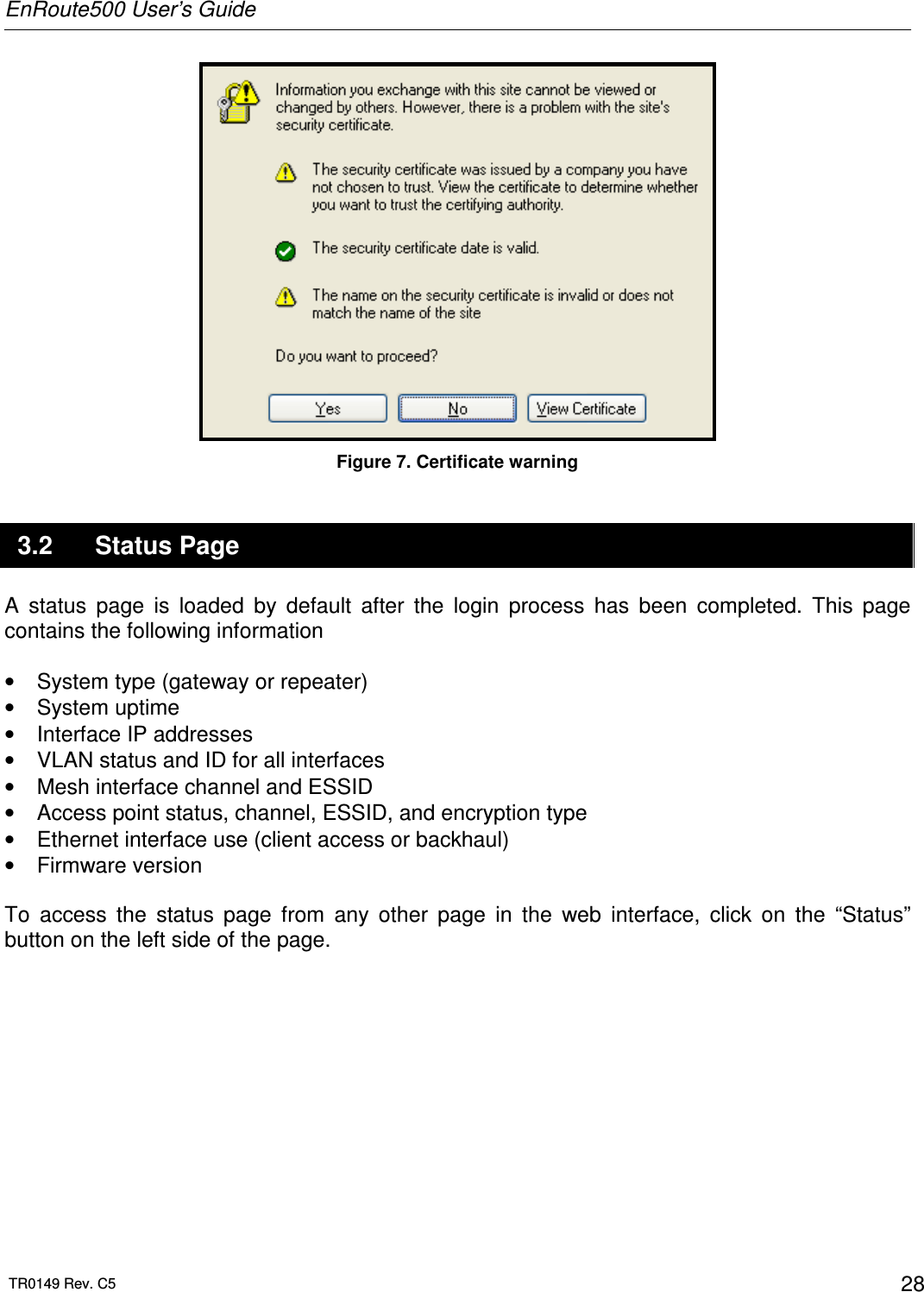
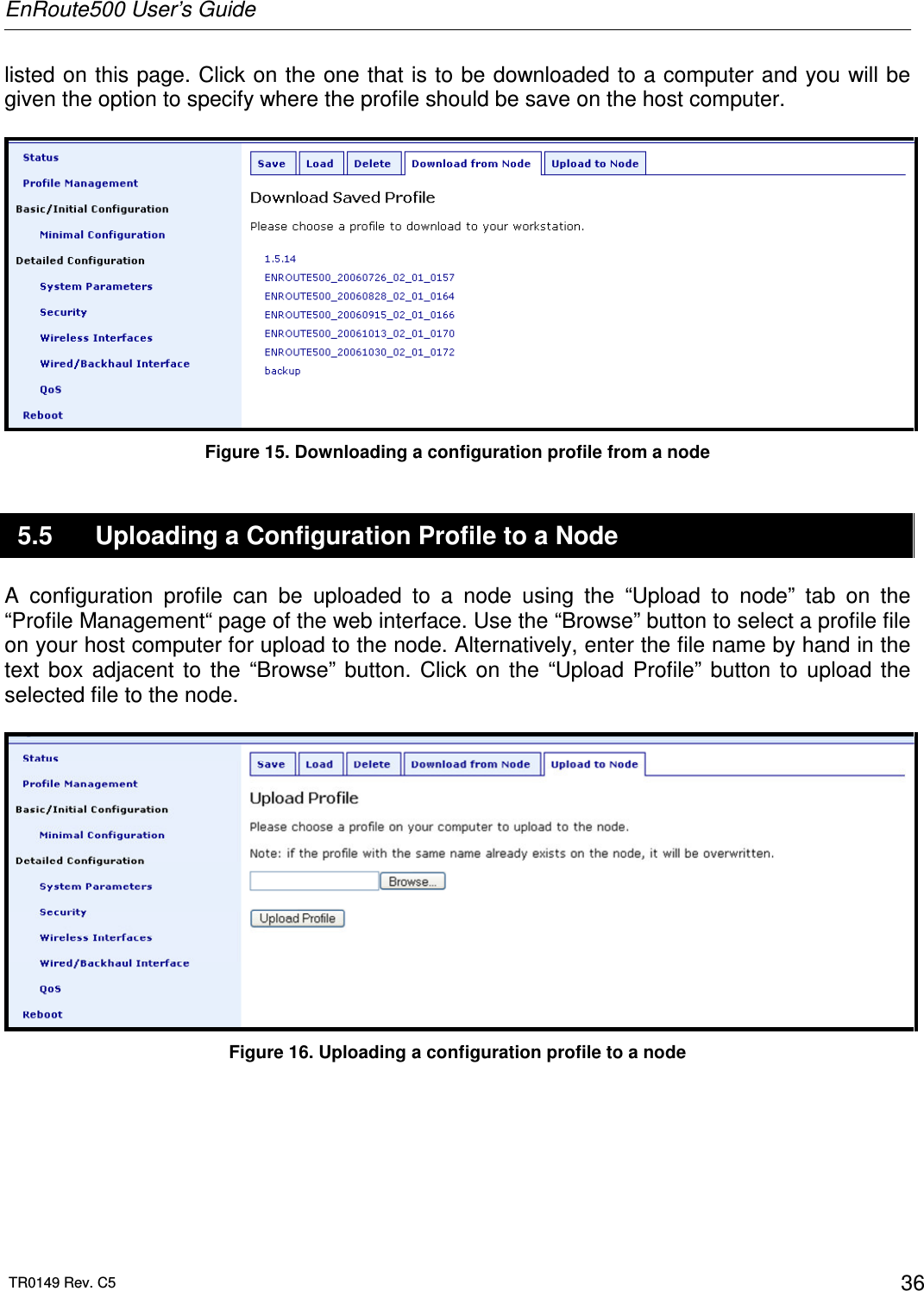
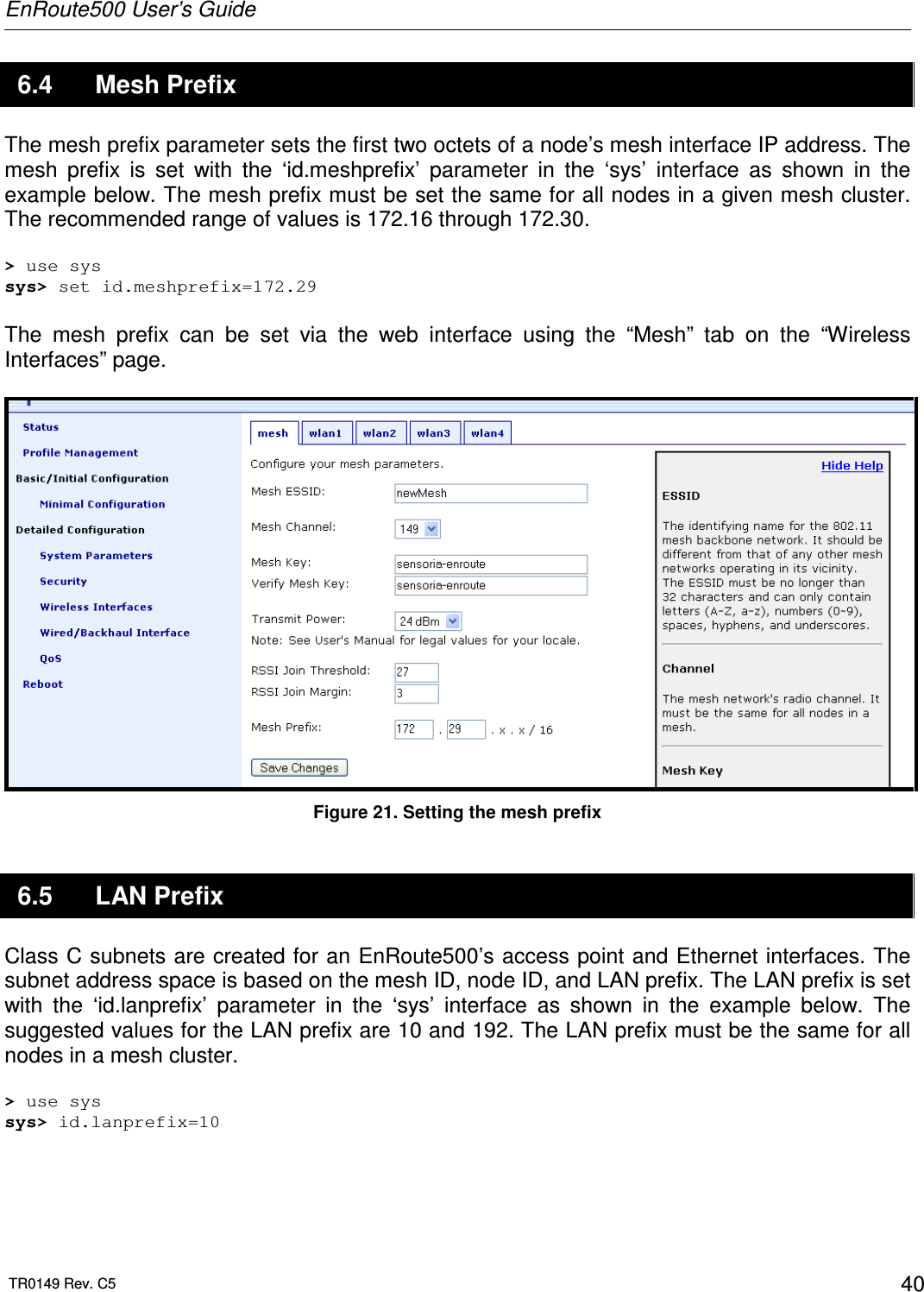
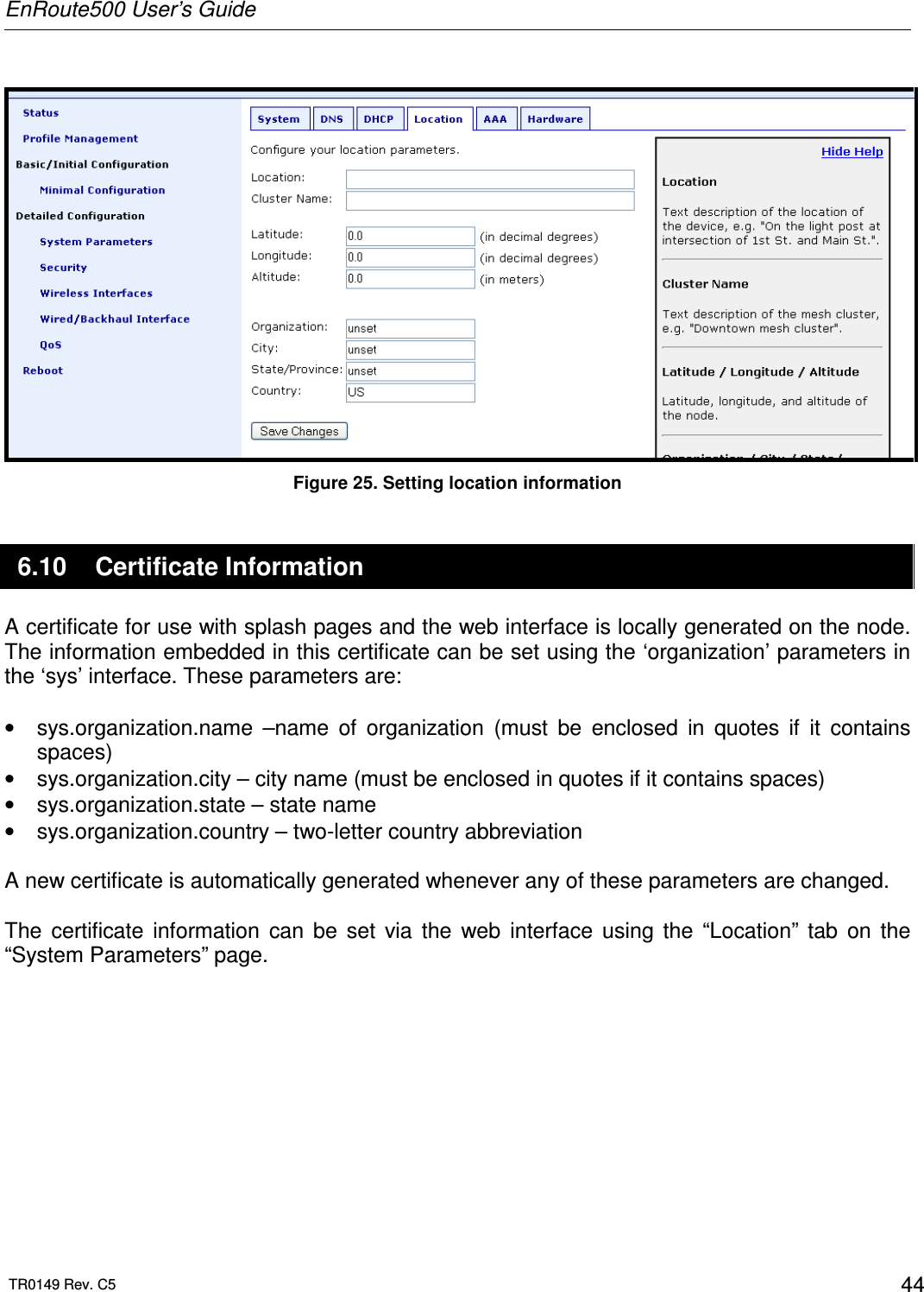
![EnRoute500 User’s Guide TR0149 Rev. C5 18 2.5.3 ‘help’ command Syntax help [command|parameter] where [command] is one of the CLI commands or [parameter] is a parameter in the currently selected interface. Description When no argument follows the help command, a help menu showing a list of available commands is displayed. When a command is supplied as the argument, a help message for that particular command is displayed. When a parameter in the current interface is specified as the argument, help information for it is displayed. Example help get will display the help information for the ‘get’ command. With the ‘sys’ interface selected sys> help scheme displays help information about that ‘scheme’ parameter, as shown below scheme : wireless node type 2.5.4 ‘show’ command Syntax show Description Displays all available interfaces. An interface in this list can be selected with the ‘use’ command.](https://usermanual.wiki/Tranzeo-Wireless-Technologies/RAEKT2KN2/User-Guide-776051-Page-18.png)
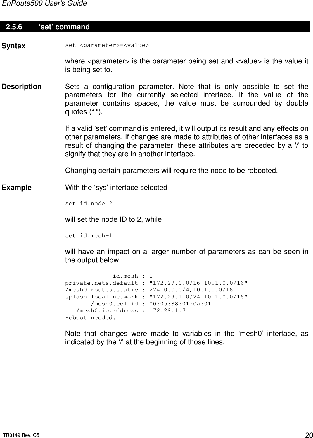
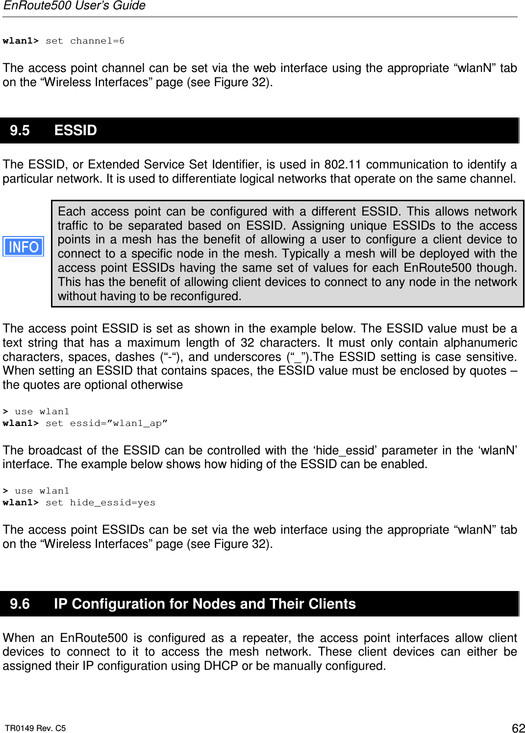
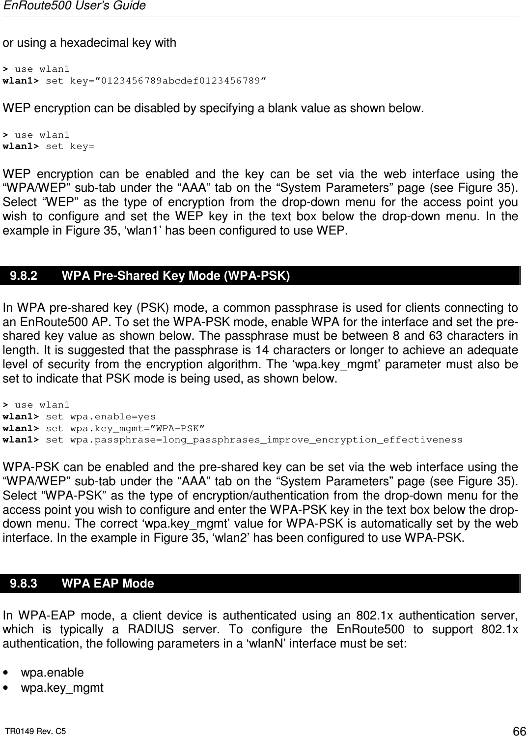
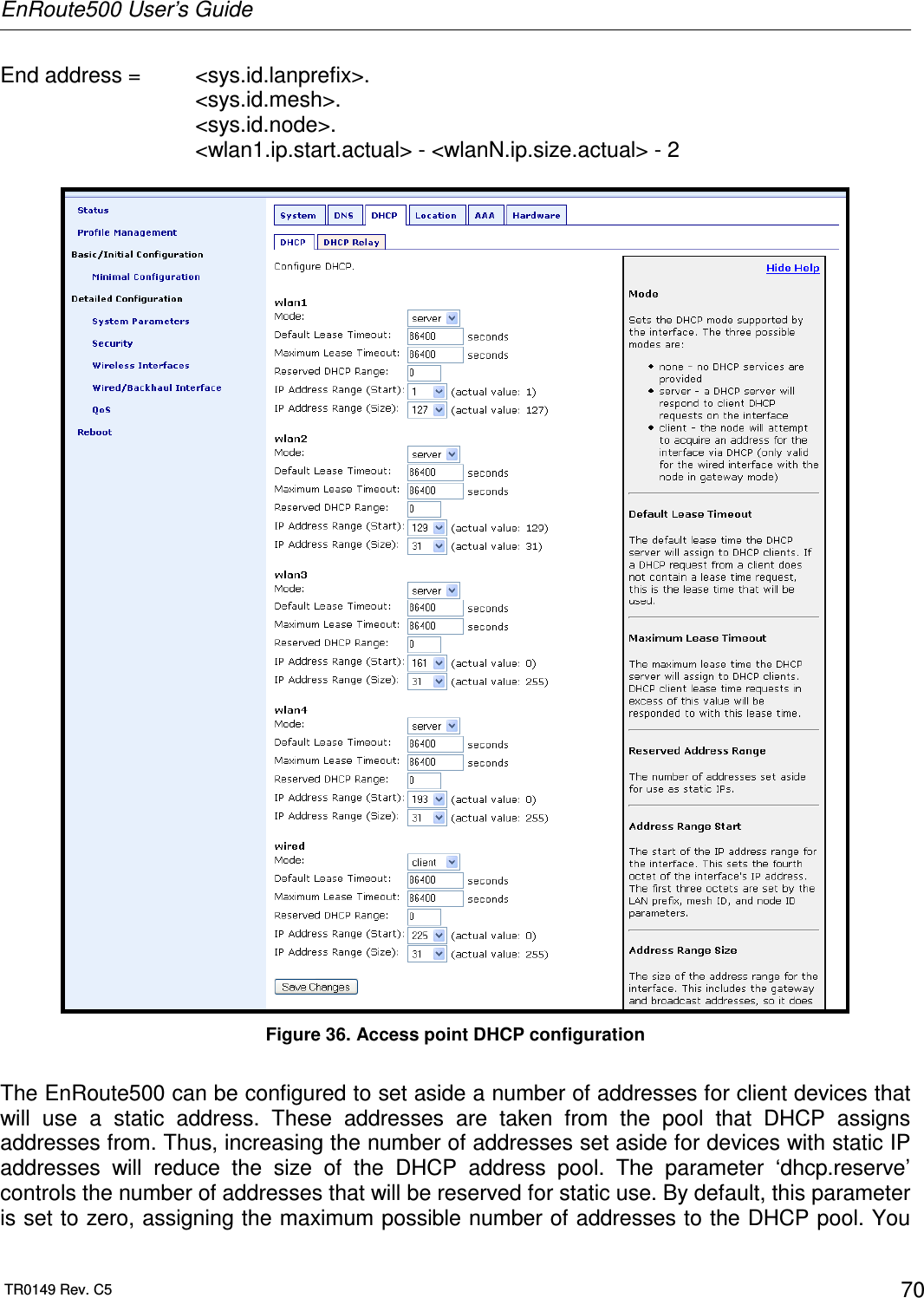
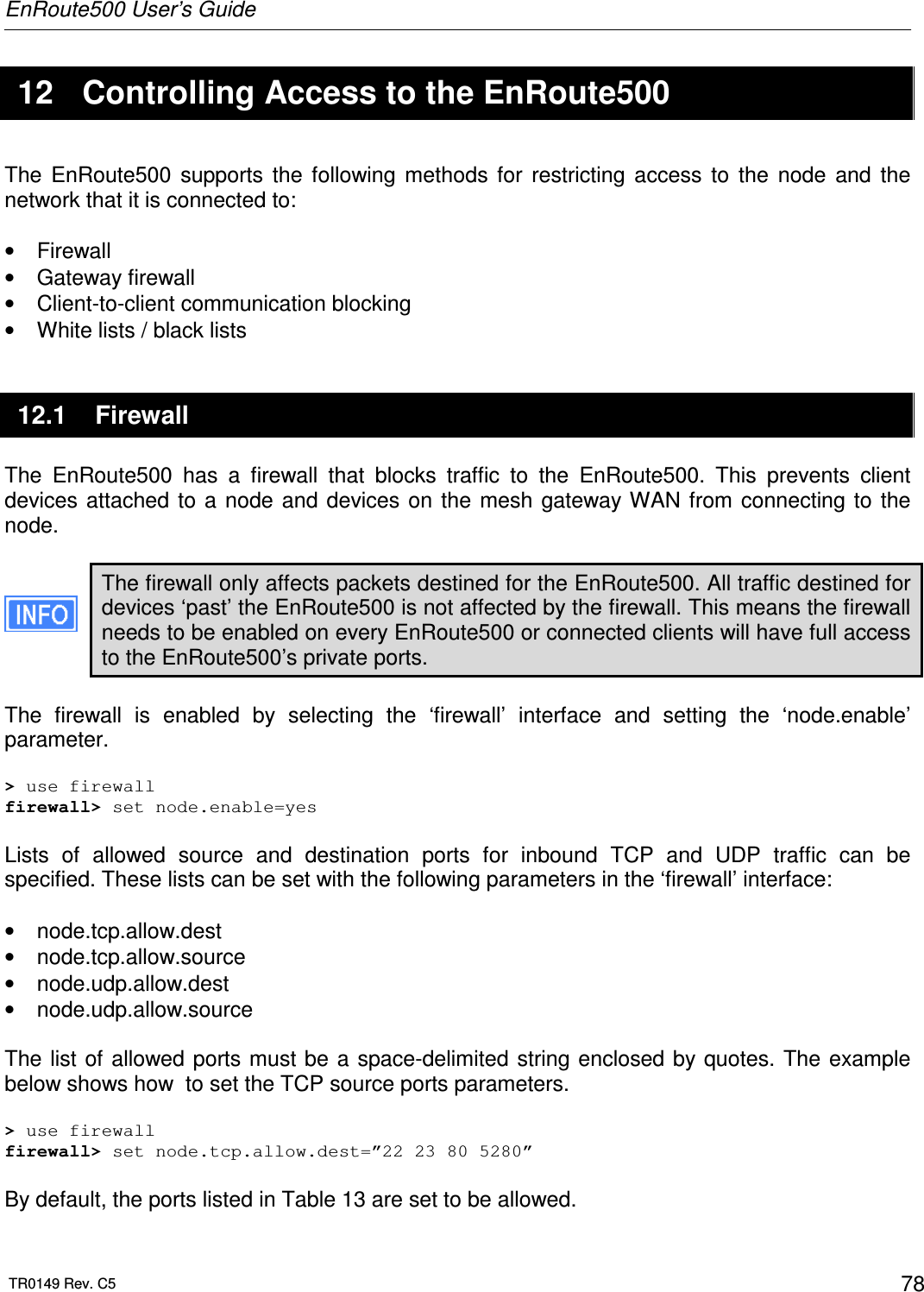
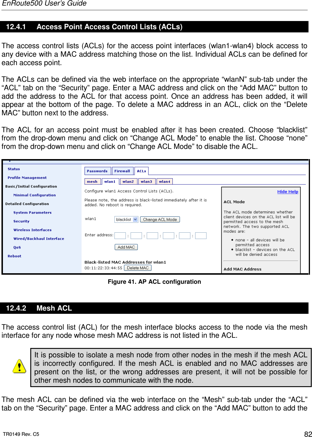
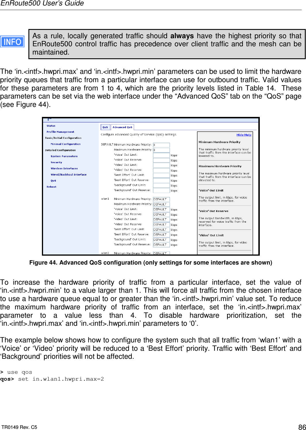
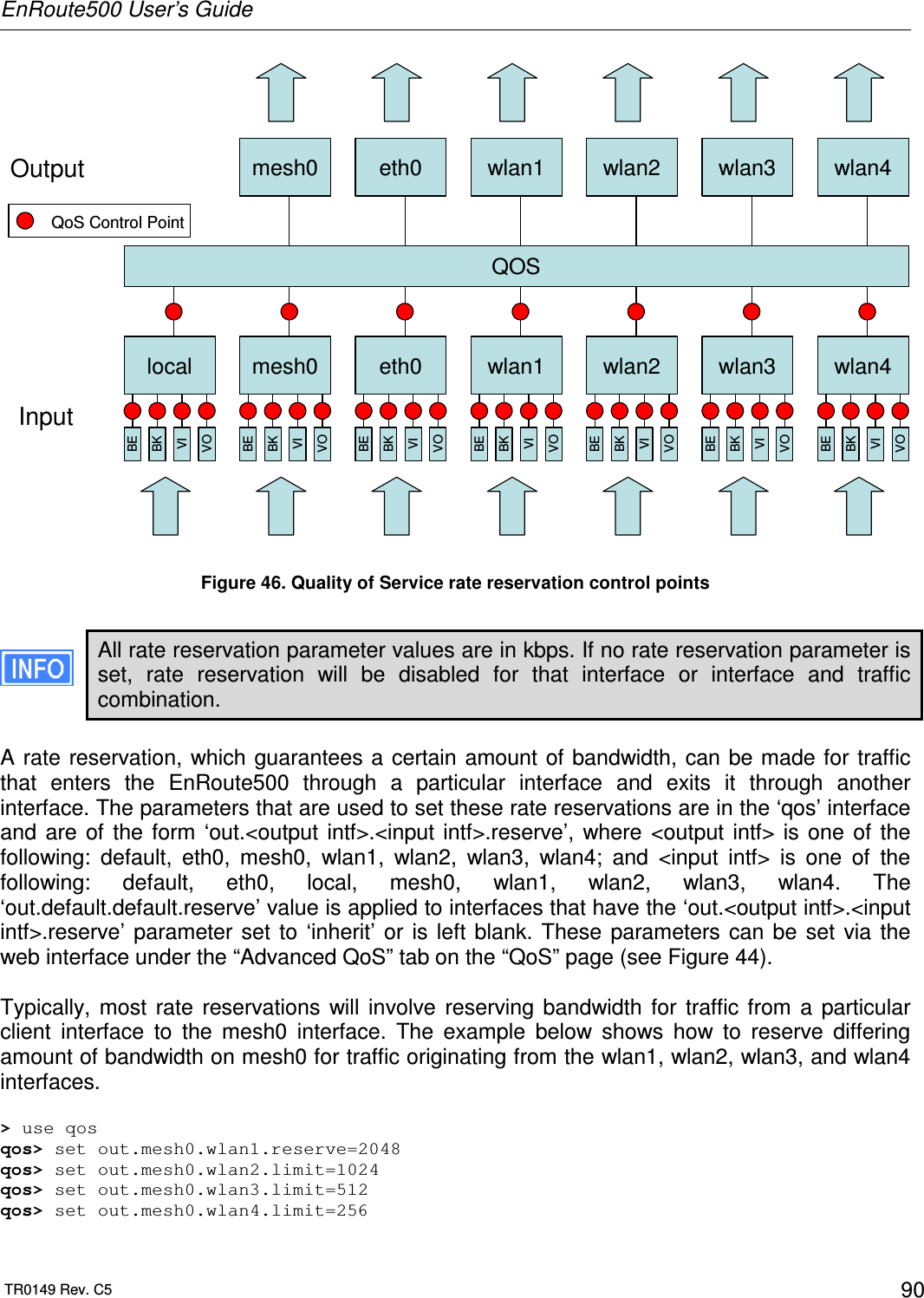
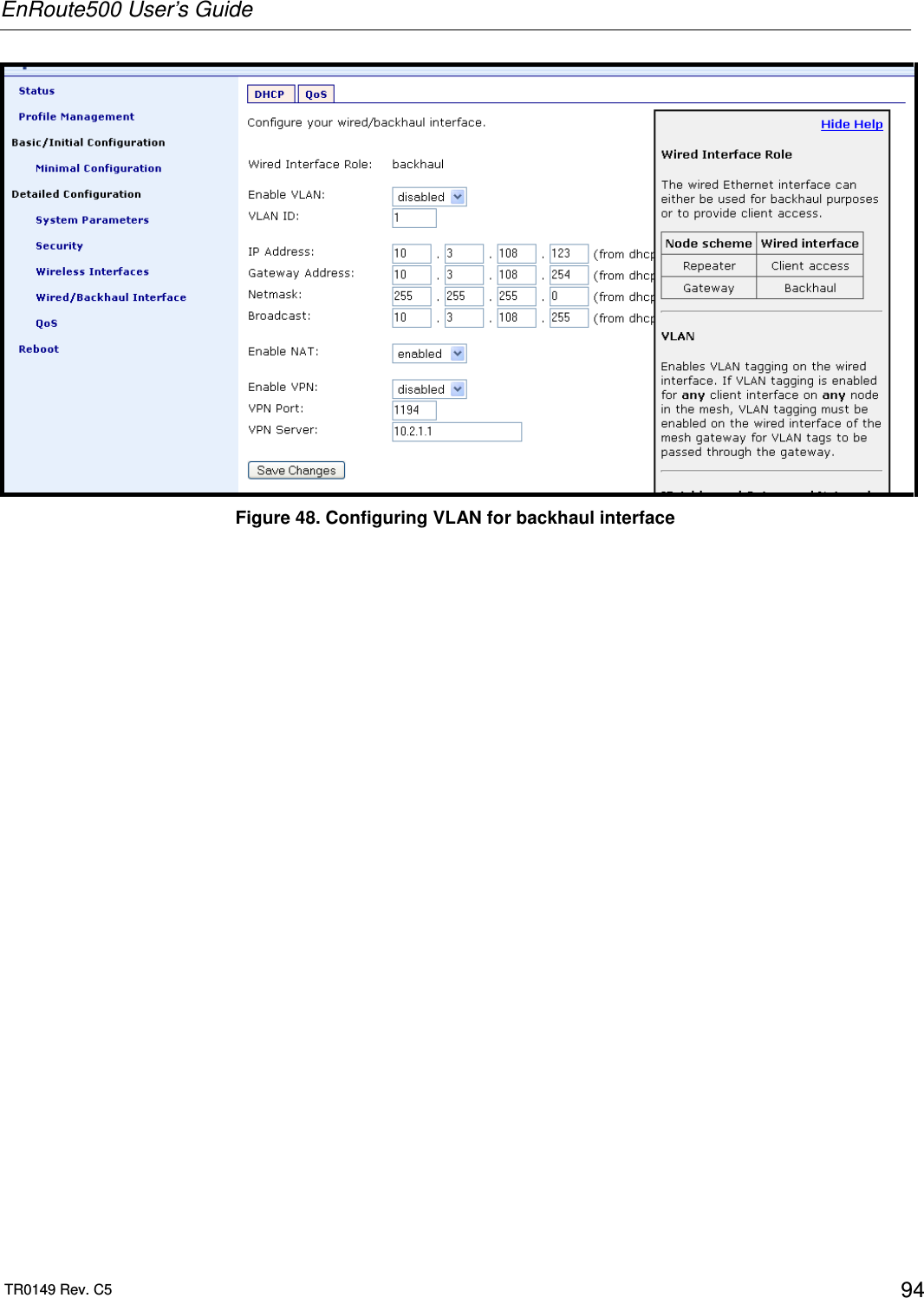
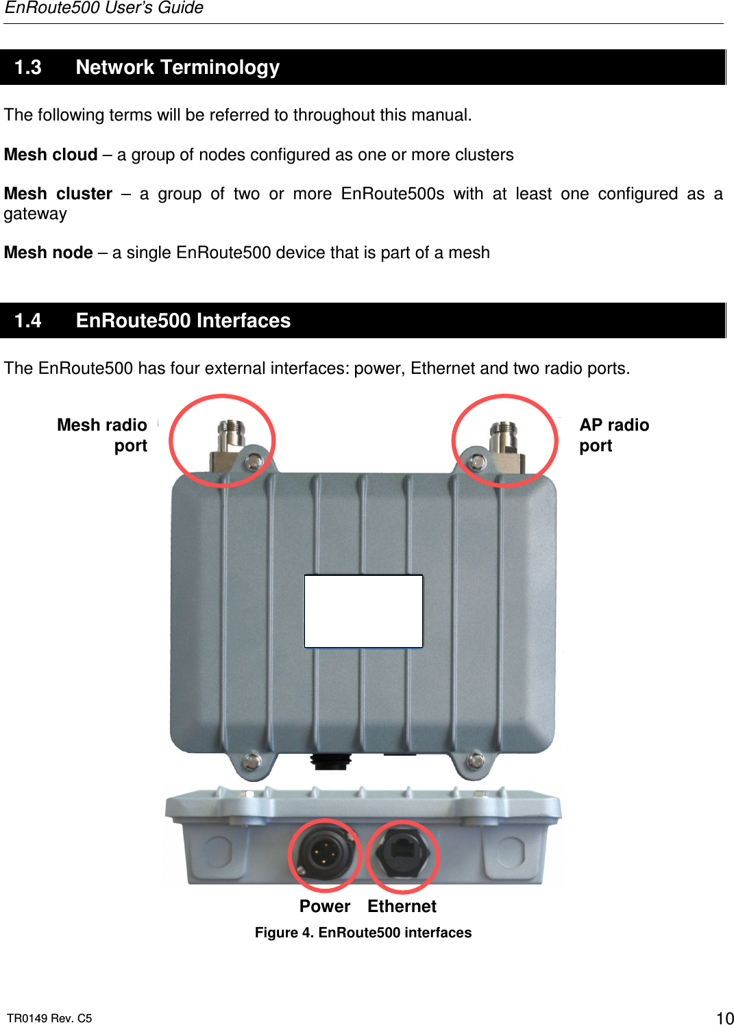
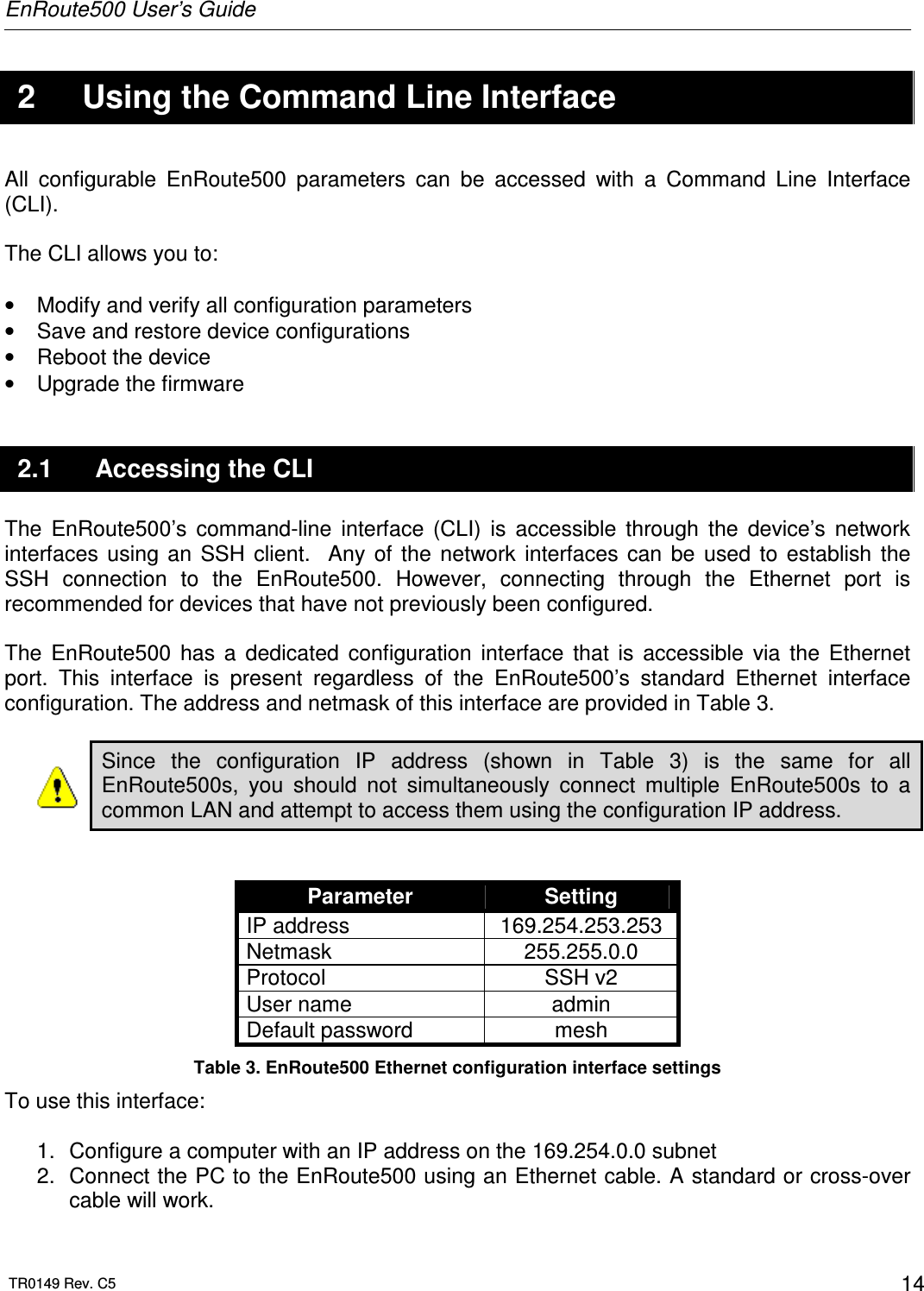
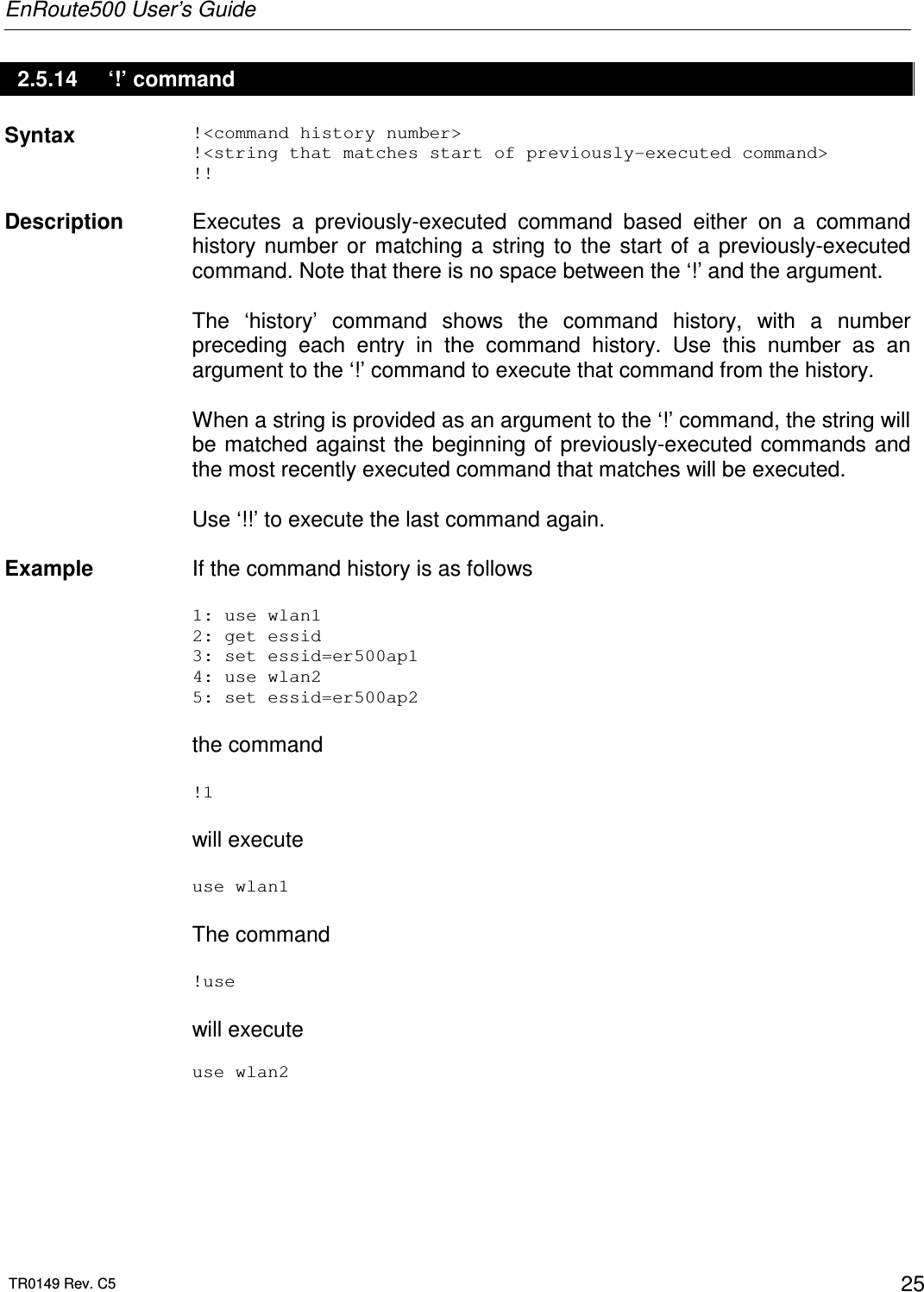
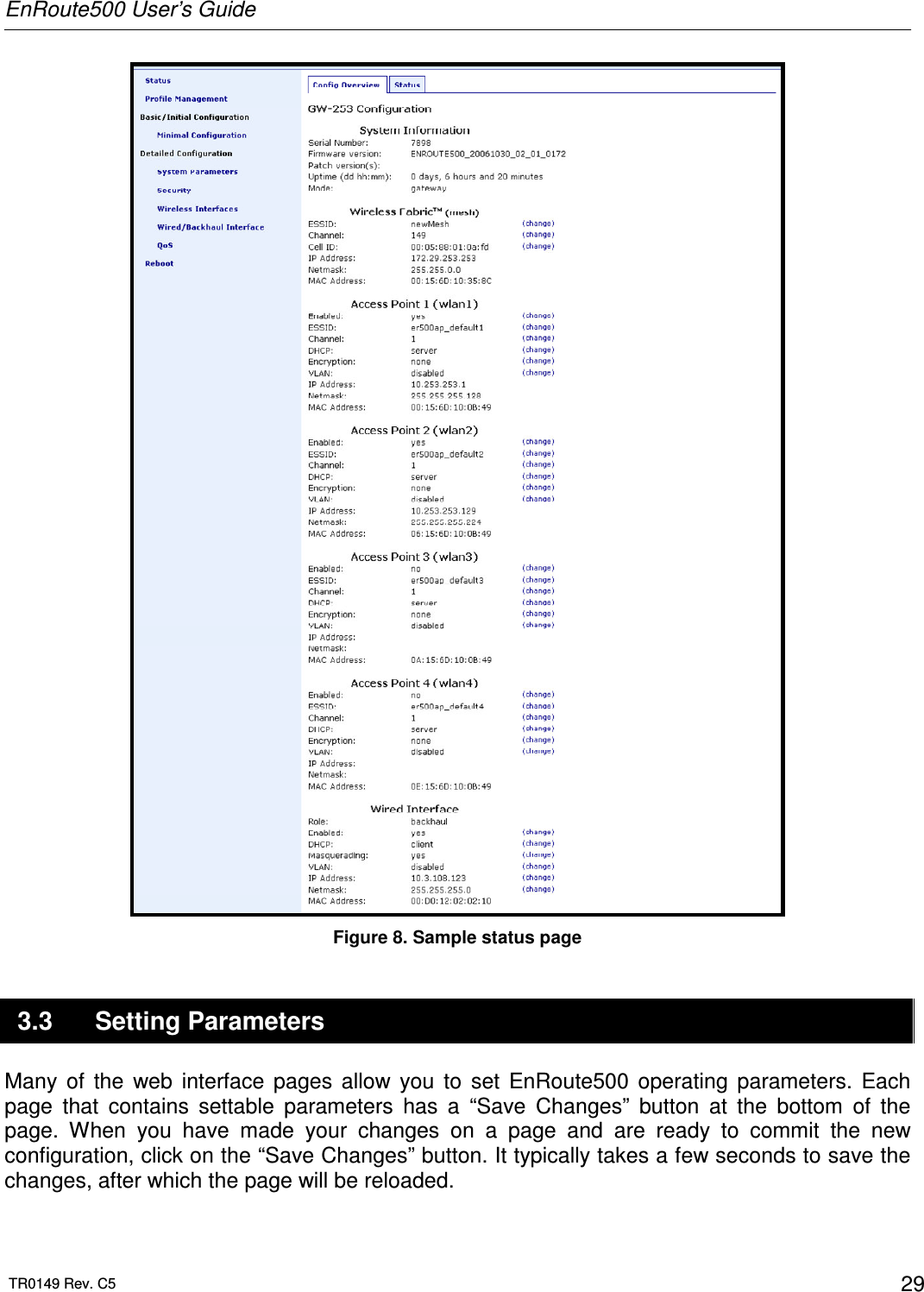
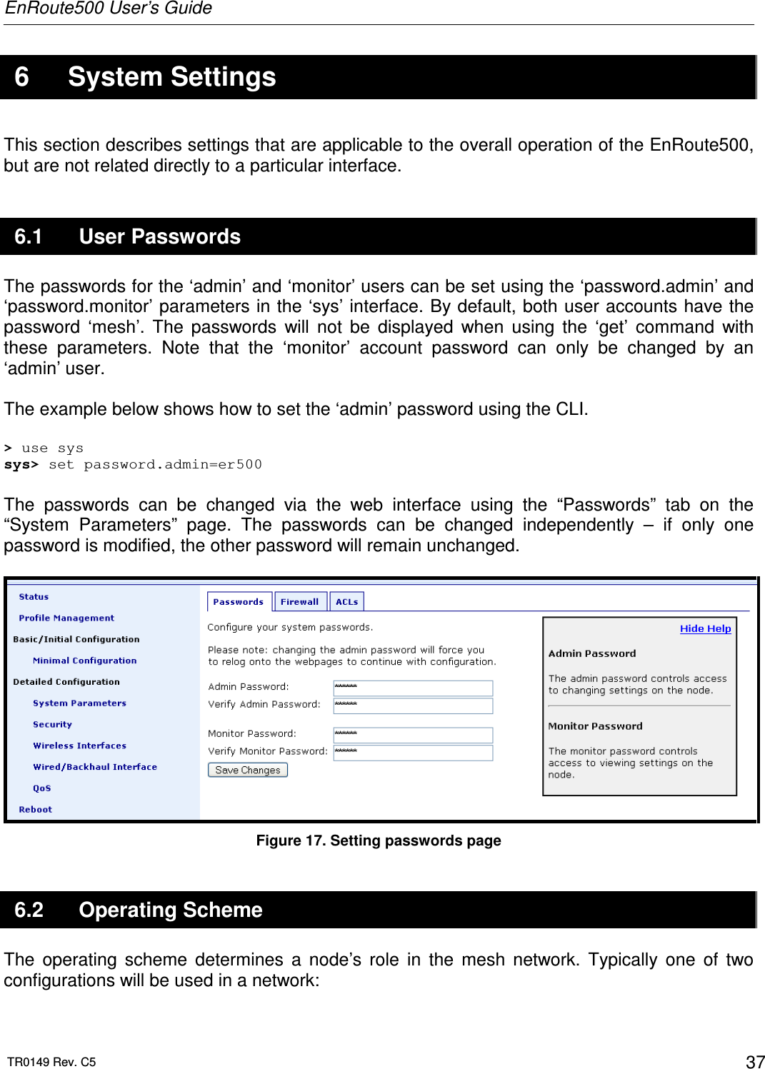
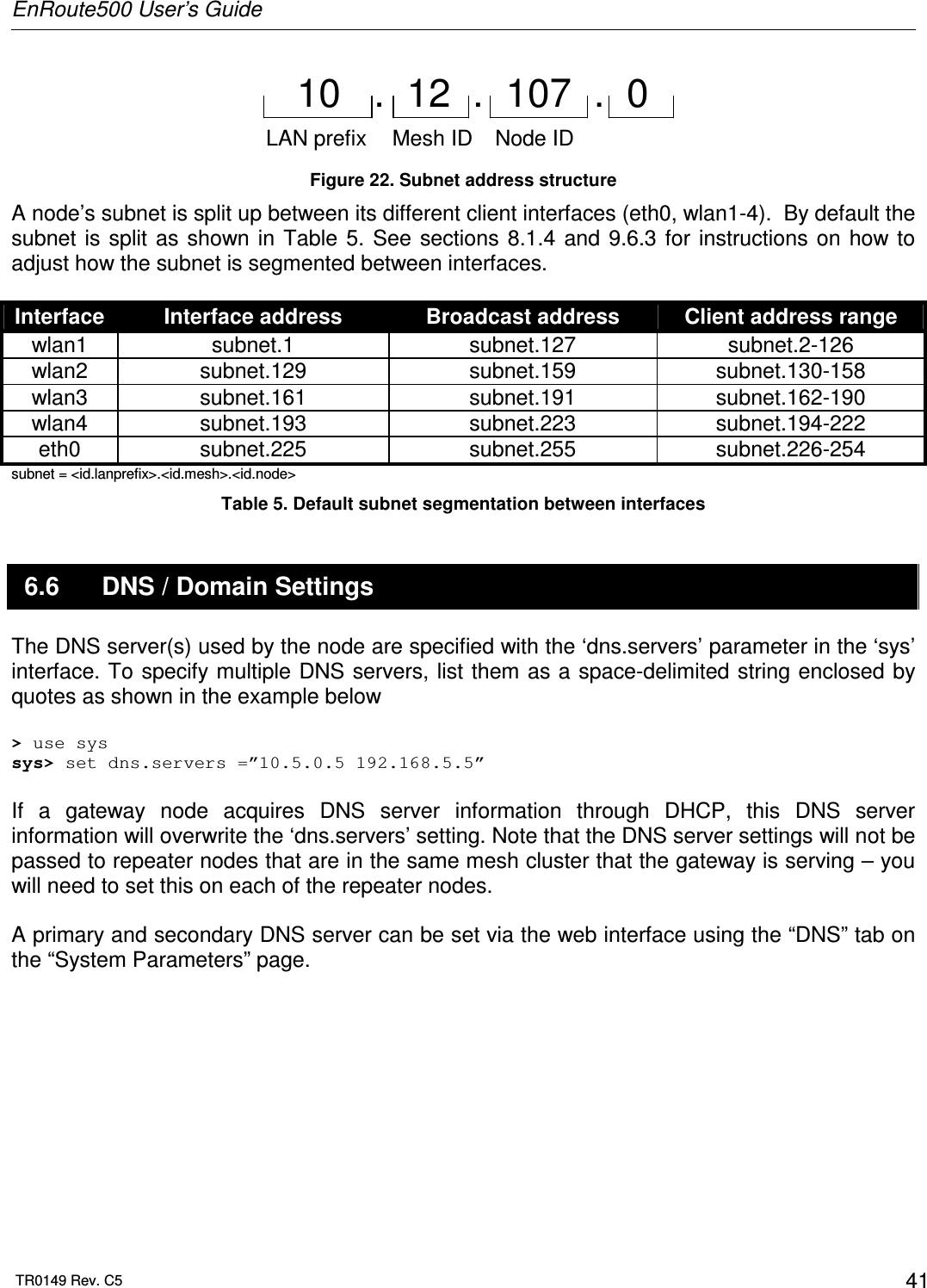
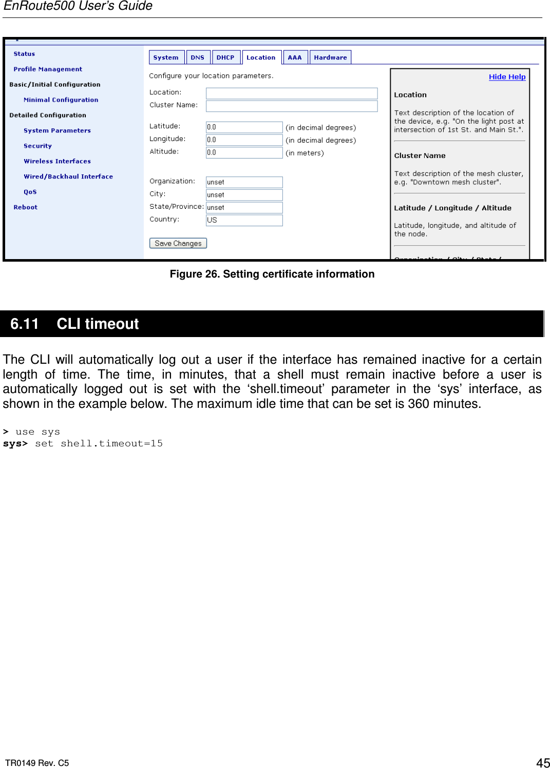
![EnRoute500 User’s Guide TR0149 Rev. C5 23 2.5.10 ‘ifconfig’ command Syntax ifconfig <eth0|wlan[0-4]> Description Displays information, such as IP address and MAC address, for a particular network interface. Example ifconfig wlan1 will display wlan1 Link encap:Ethernet HWaddr 00:15:6D:52:01:FD inet addr:10.2.10.1 Bcast:172.29.255.255 Mask:255.255.0.0 UP BROADCAST RUNNING MULTICAST MTU:1500 Metric:1 RX packets:0 errors:0 dropped:0 overruns:0 frame:0 TX packets:2434 errors:0 dropped:0 overruns:0 carrier:0 collisions:0 txqueuelen:0 RX bytes:0 (0.0 b) TX bytes:233128 (227.6 Kb) 2.5.11 ‘route’ command Syntax route Description Displays the current route table. 2.5.12 ‘clear’ command Syntax clear Description Clears the screen](https://usermanual.wiki/Tranzeo-Wireless-Technologies/RAEKT2KN2/User-Guide-776051-Page-23.png)
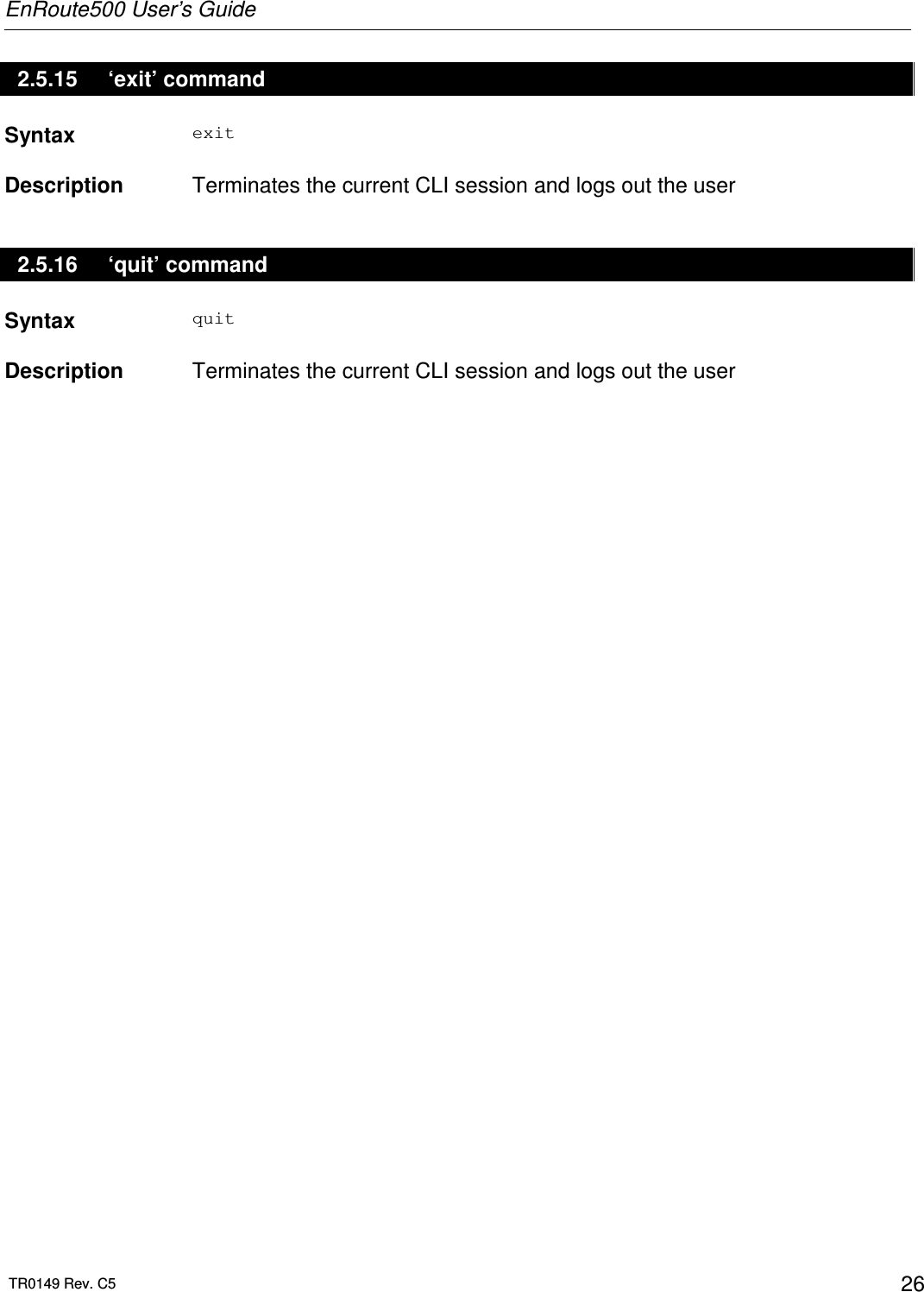
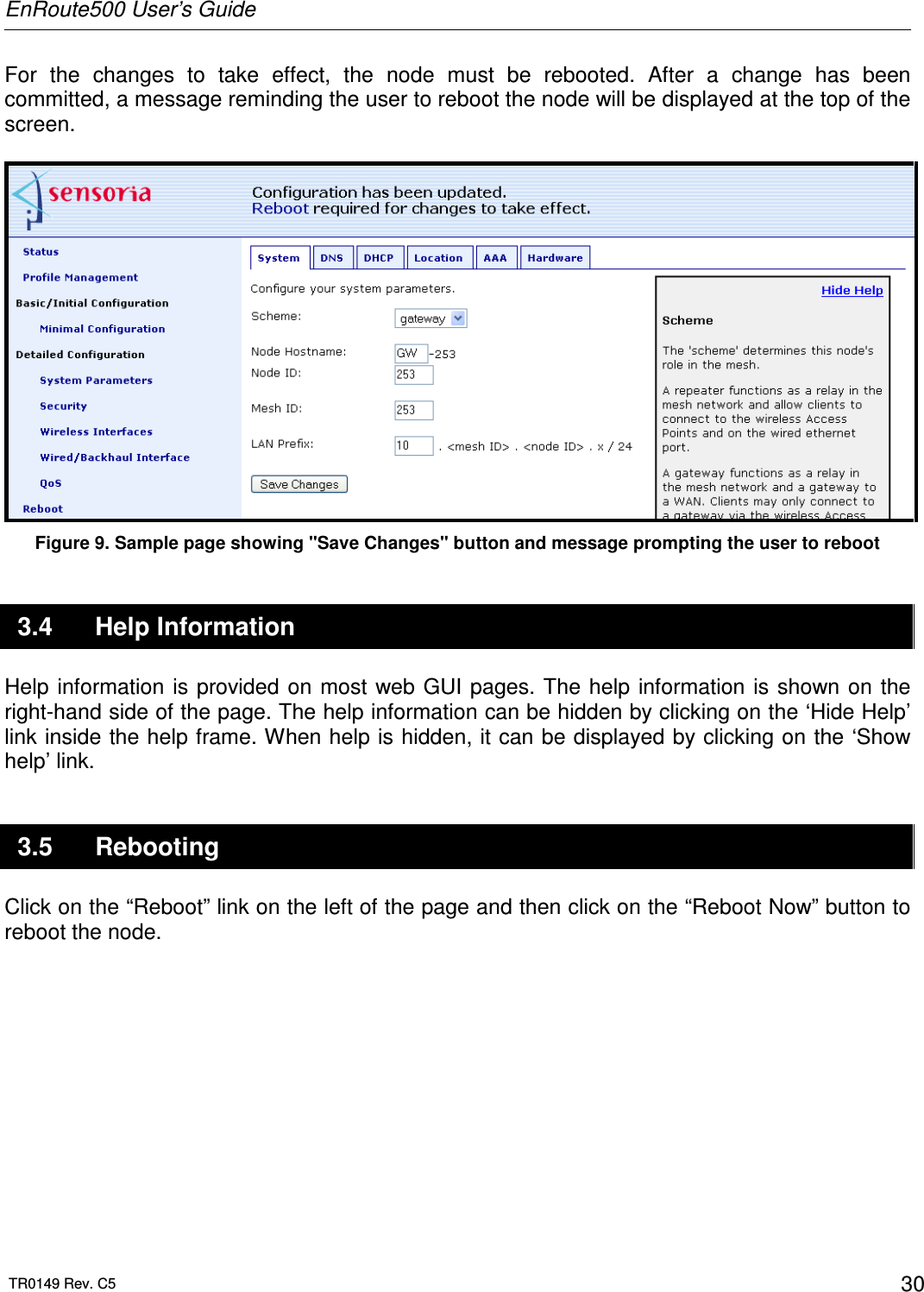
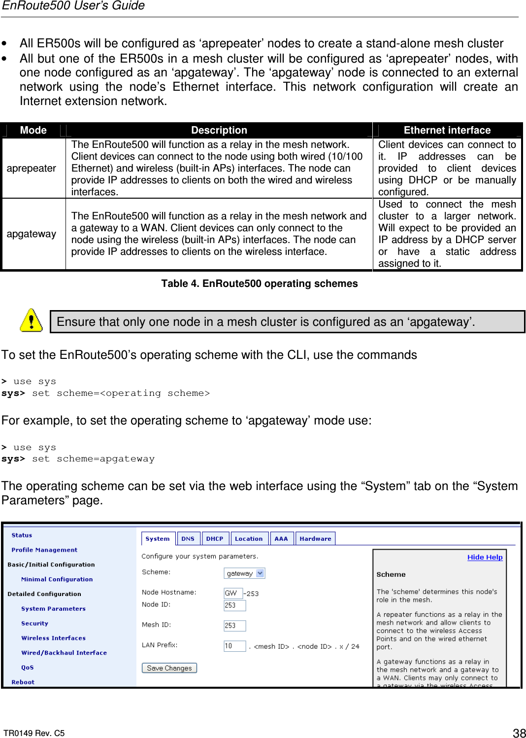
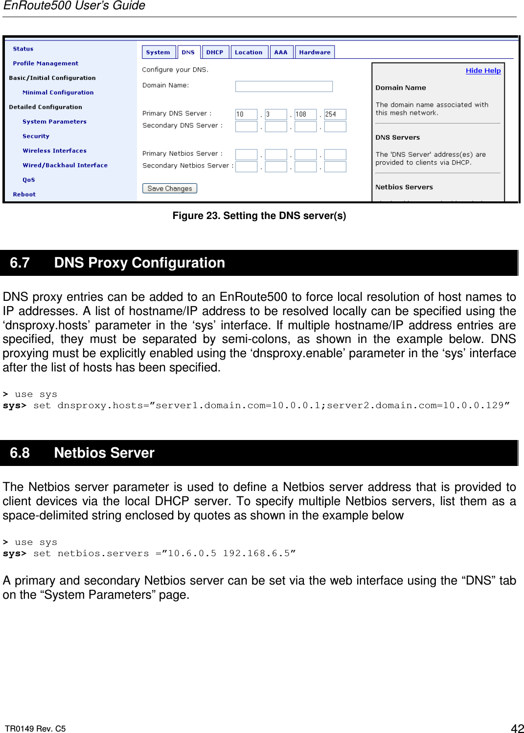
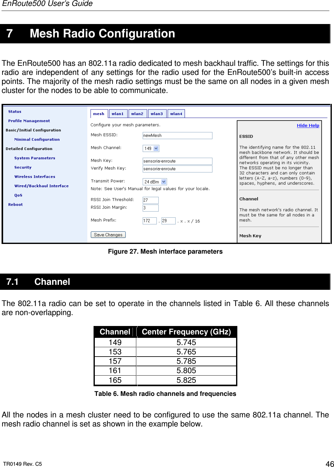
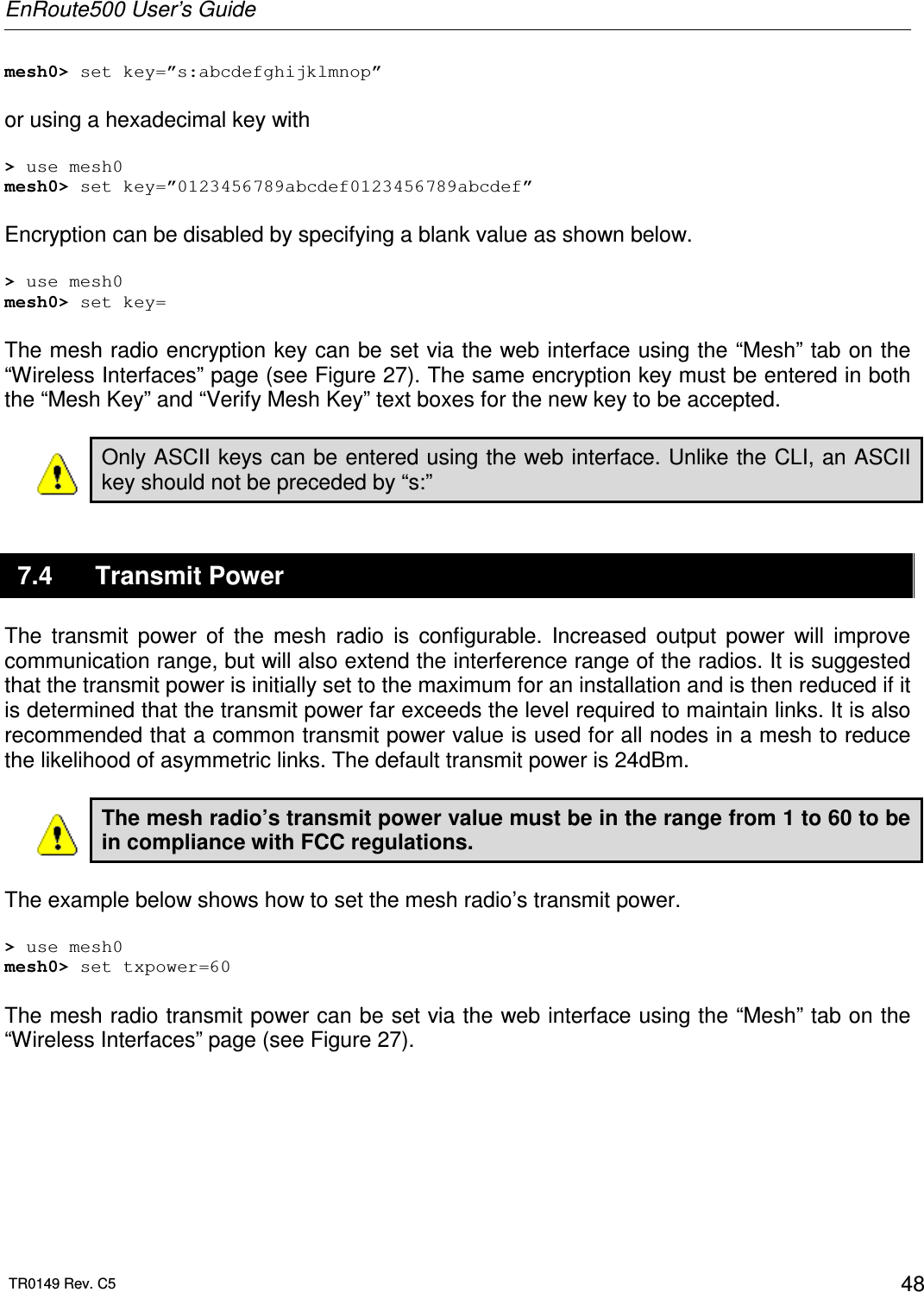
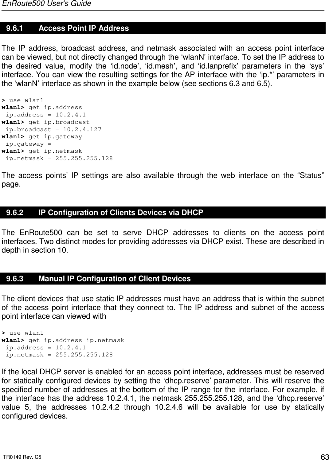
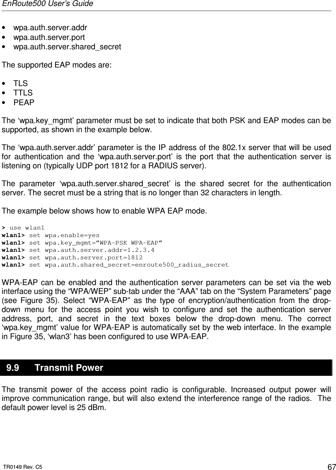
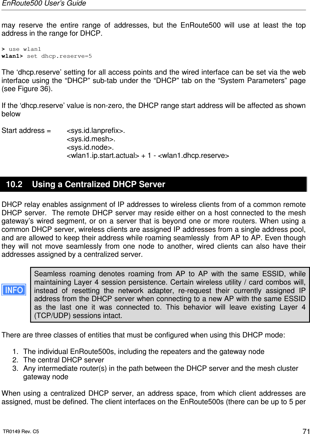
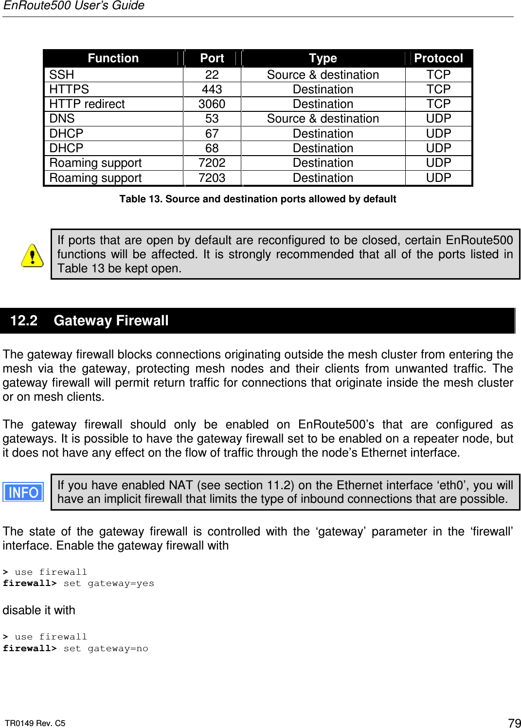
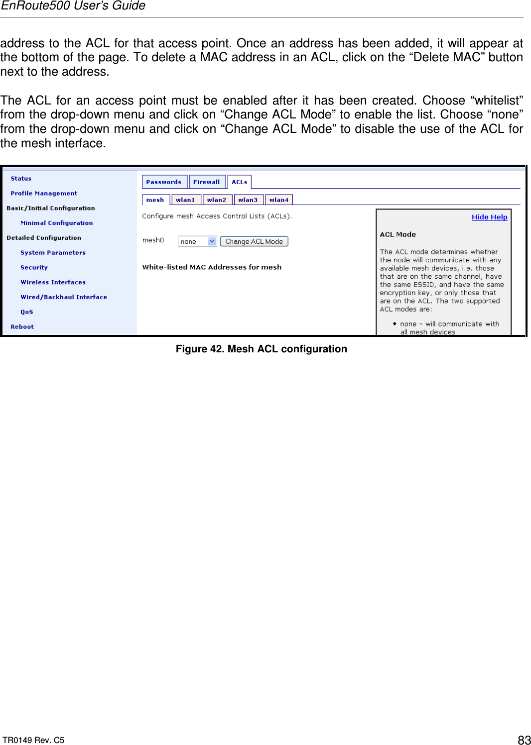
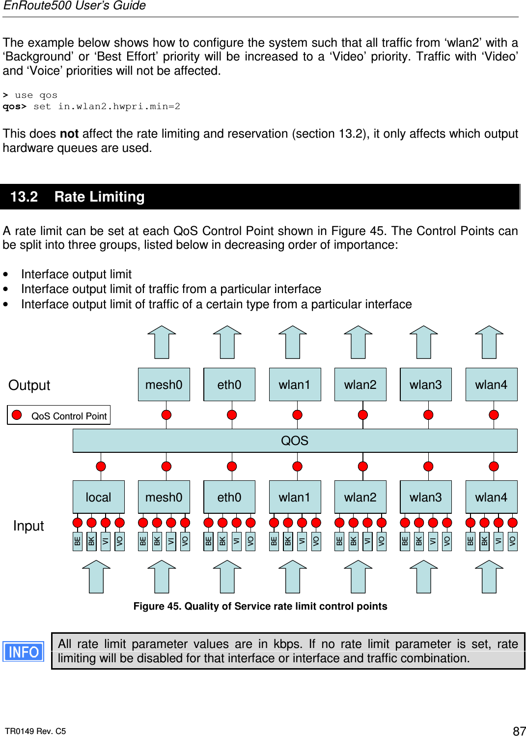
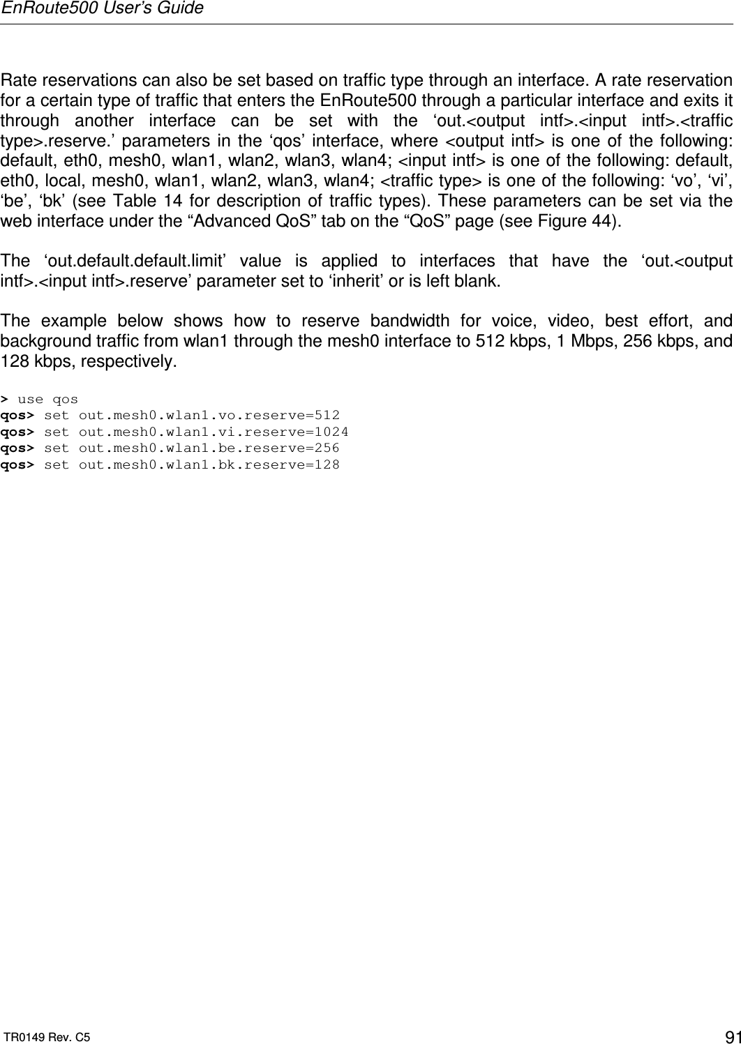
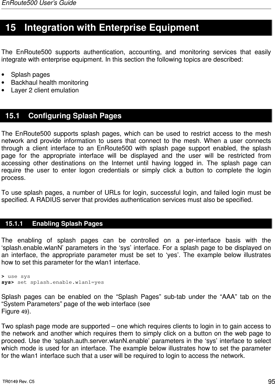
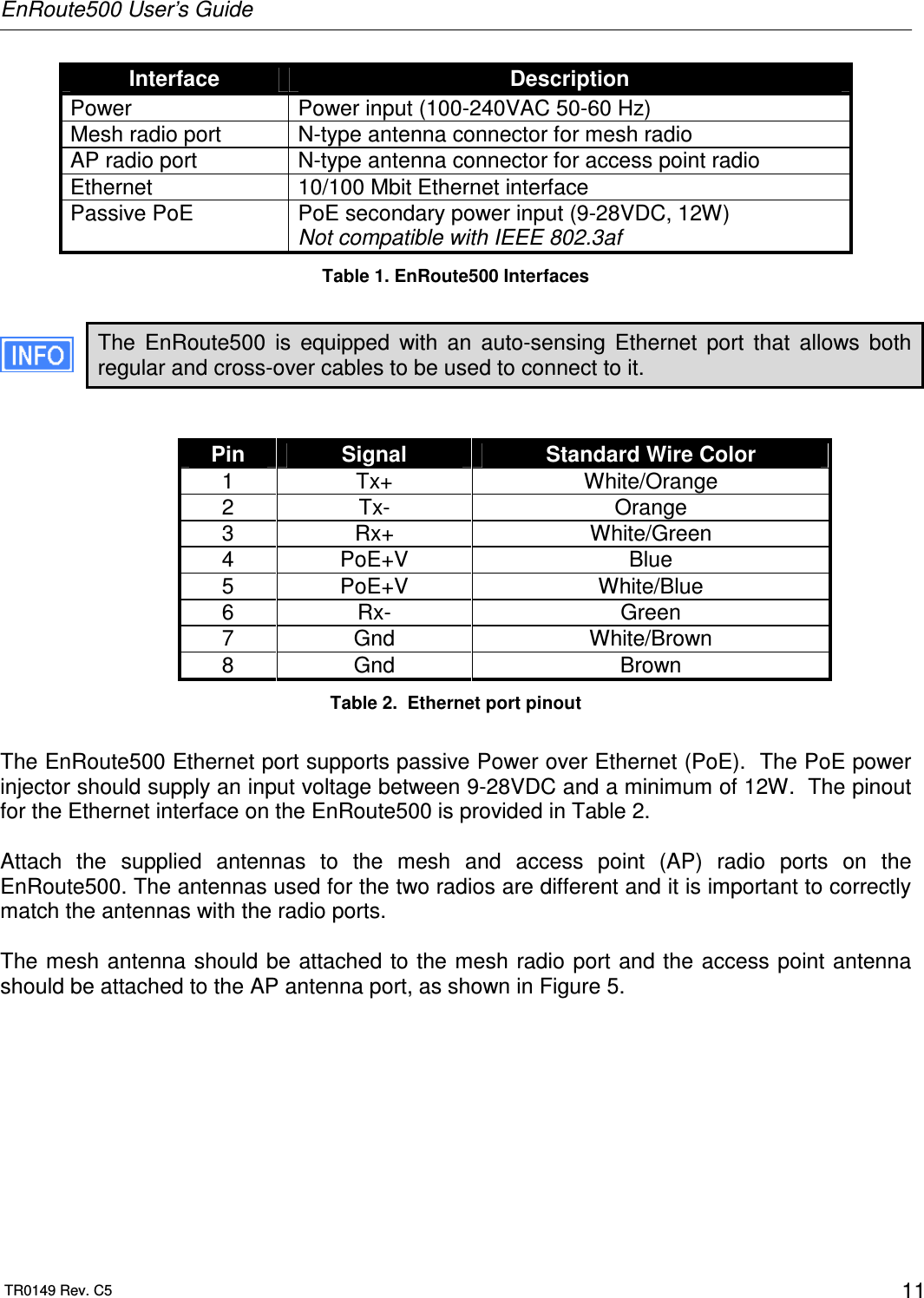
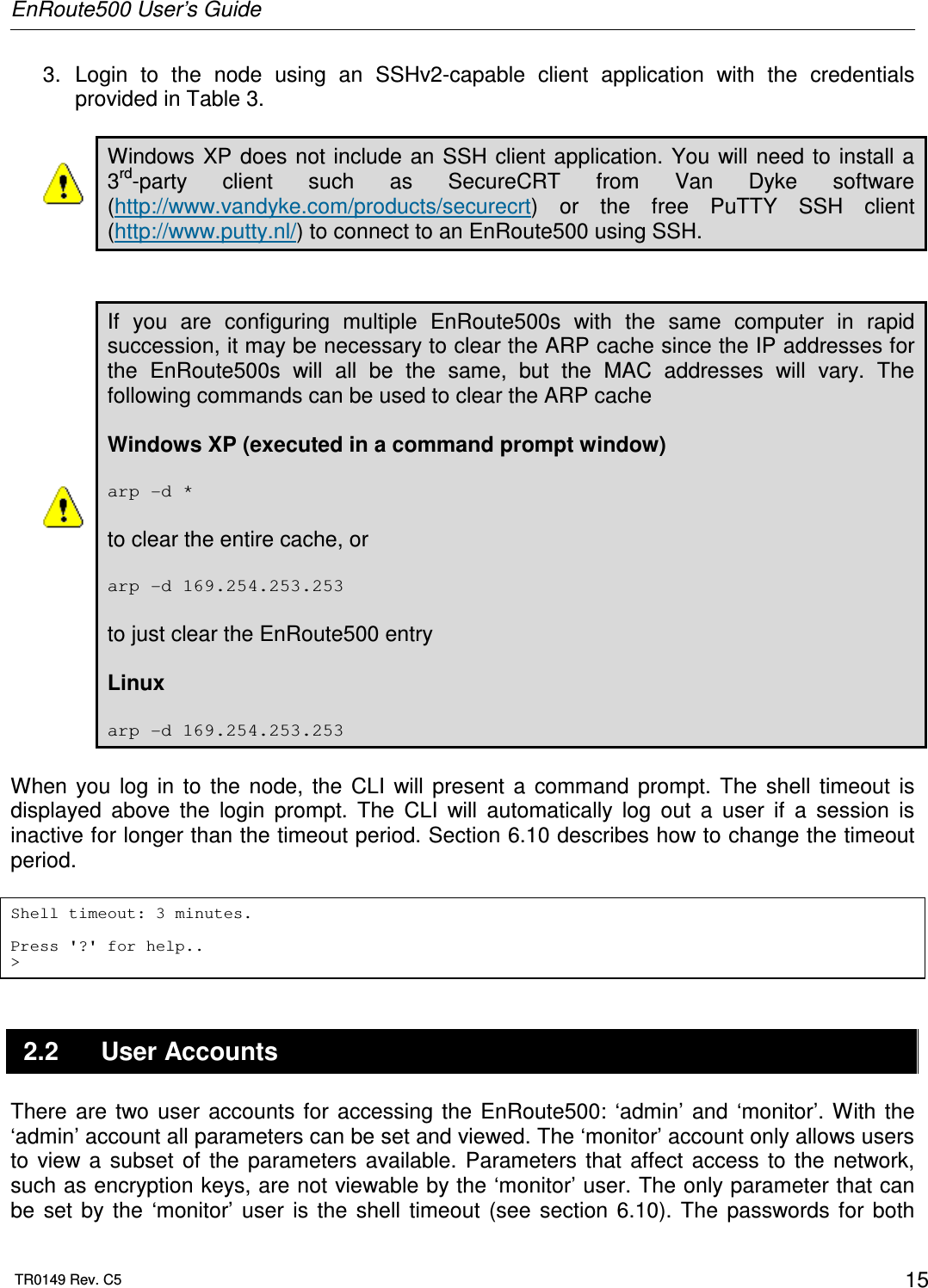
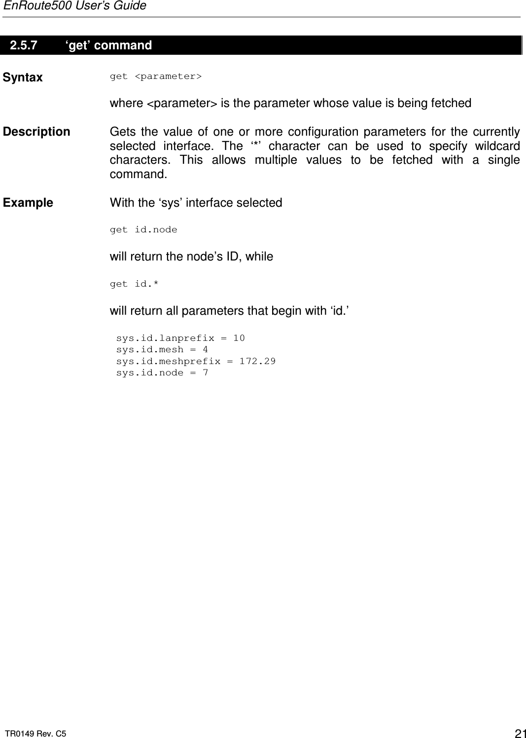
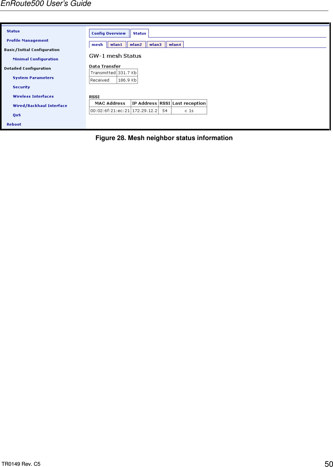
![EnRoute500 User’s Guide TR0149 Rev. C5 49 txpower Output Power (dBm) 1 9 9 10 14 12 18 14 22 16 26 18 29 20 33 22 60 24 Table 7. Mesh radio output power settings 7.5 IP Configuration The IP address, broadcast address, and netmask associated with the mesh radio interface can be viewed, but not directly changed through the ‘mesh’ interface. To change the IP settings, the ‘id’ settings in the ‘sys’ interface, from which the IP settings are derived, must be changed (see sections 6.3 and 6.4). The IP settings can be viewed with > use mesh0 mesh0> get ip.address ip.address = 172.29.2.4 [read-only] mesh0> get ip.broadcast ip.broadcast = 172.29.255.255 [read-only] mesh0> get ip.gateway ip.gateway = [read-only] mesh0> get ip.netmask ip.netmask = 255.255.0.0 [read-only] The mesh radio IP settings are also available through the web interface on the “Status” page. 7.6 Neighbor Status Information on mesh neighbors is provided on the mesh status page, accessible under the ‘Status’ tab on the ‘Status’ page. The signal strength of each neighbor device, it’s MAC address, its IP address, and the time since data was last received from it are listed. A sample of the mesh neighbor status page is shown in Figure 28.](https://usermanual.wiki/Tranzeo-Wireless-Technologies/RAEKT2KN2/User-Guide-776051-Page-49.png)
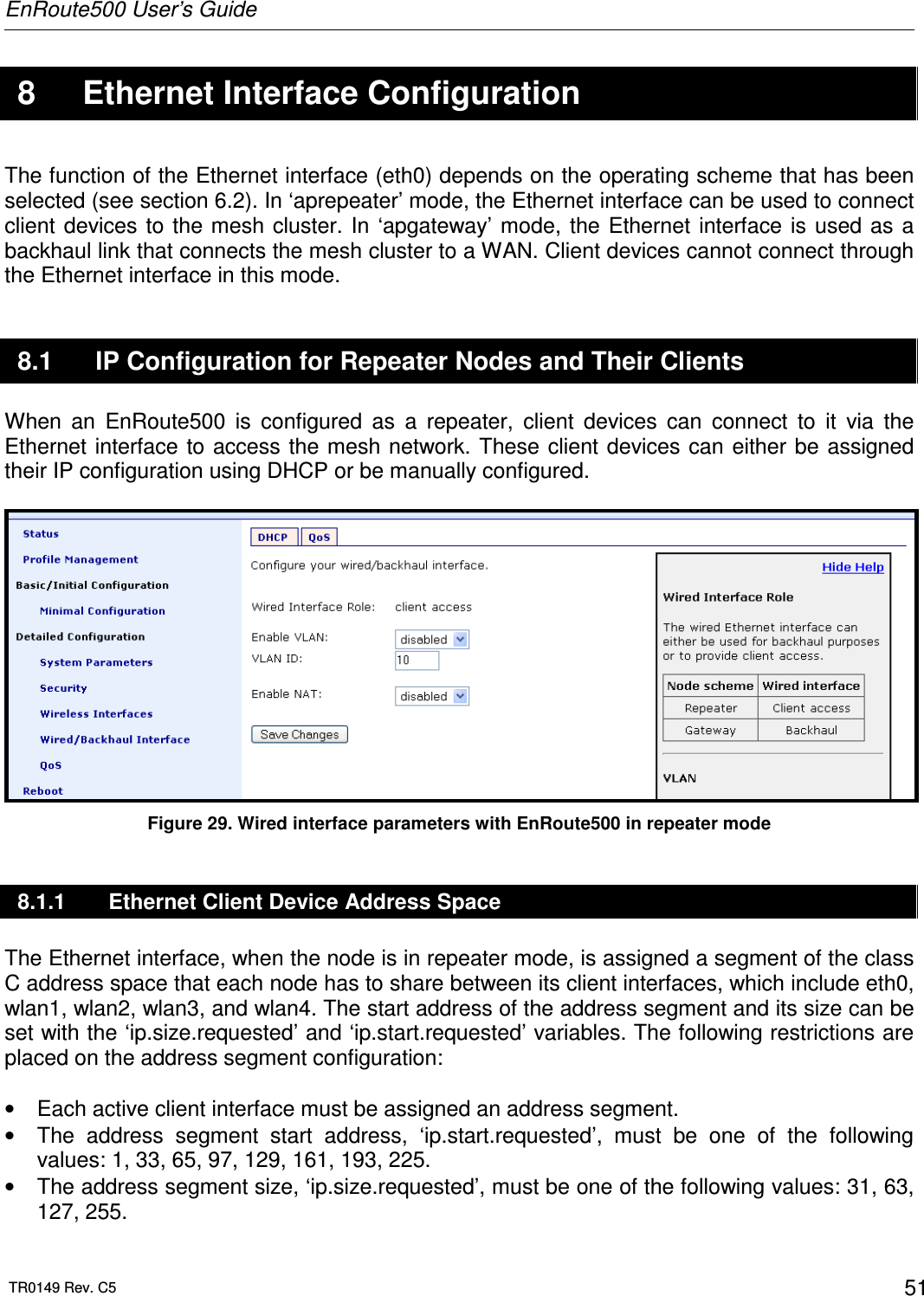
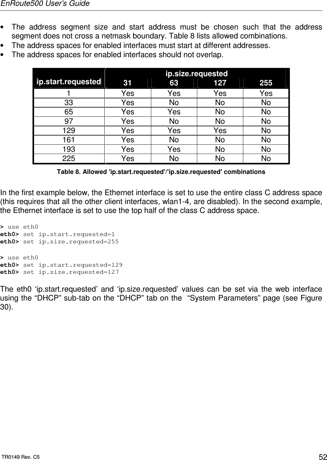
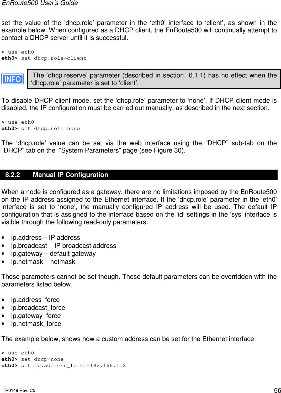
![EnRoute500 User’s Guide TR0149 Rev. C5 54 8.1.2 Ethernet Interface IP Address The EnRoute500’s Ethernet interface address should not be changed directly using the ‘ip.*’ parameters in the ‘eth0’ interface when it is in repeater mode. To set the IP address to the desired value, modify the ‘id.node’, ‘id.mesh’, and ‘id.lanprefix’ parameters in the ‘sys’ interface and the ‘ip.start.requested’ parameter in the ‘eth0’ interface (see sections 6.3 and 6.5). You can view the resulting settings for the Ethernet interface with the ‘ip.*’ parameters in the ‘eth0’ interface as shown in the example below. > use eth0 eth0> get ip.* ip.address = 10.2.4.225 [read-only] ip.address_force = ip.broadcast = 10.2.4.255 [read-only] ip.broadcast_force = ip.gateway = [read-only] ip.gateway_force = ip.netmask = 255.255.255.0 [read-only] ip.netmask_force = ip.size.actual = [read-only] ip.size.requested = 31 ip.start.actual = [read-only] ip.start.requested = 225 The Ethernet IP settings are also available through the web interface on the “Status” page. It is strongly recommended that all the ‘ip.*_force’ variables are cleared when the EnRoute500 is configured as a repeater. This ensures that the Ethernet interfaces settings are inherited from the ‘id.*’ settings in the ‘sys’ interface and client devices will get addresses that the mesh can route to. 8.1.3 IP Configuration of Clients Devices via DHCP When configured as a repeater, the EnRoute500 can be set to serve DHCP addresses to clients on the Ethernet interface. Two distinct modes for providing addresses via DHCP exist. These are described in depth in section 10. 8.1.4 Manual IP Configuration of Client Devices The client devices connected via the Ethernet interface that use static IP addresses must have addresses that are within the subnet of the Ethernet interface. The IP address and subnet of the Ethernet interface can viewed with > use eth0 eth0> get ip.address ip.netmask eth0.ip.address = 10.2.4.225 [read-only]](https://usermanual.wiki/Tranzeo-Wireless-Technologies/RAEKT2KN2/User-Guide-776051-Page-54.png)
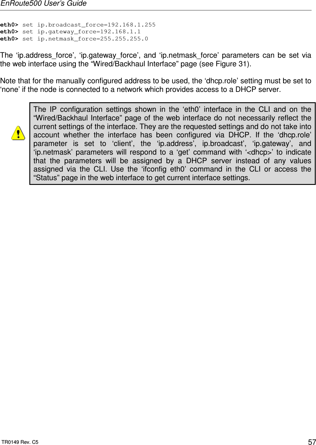
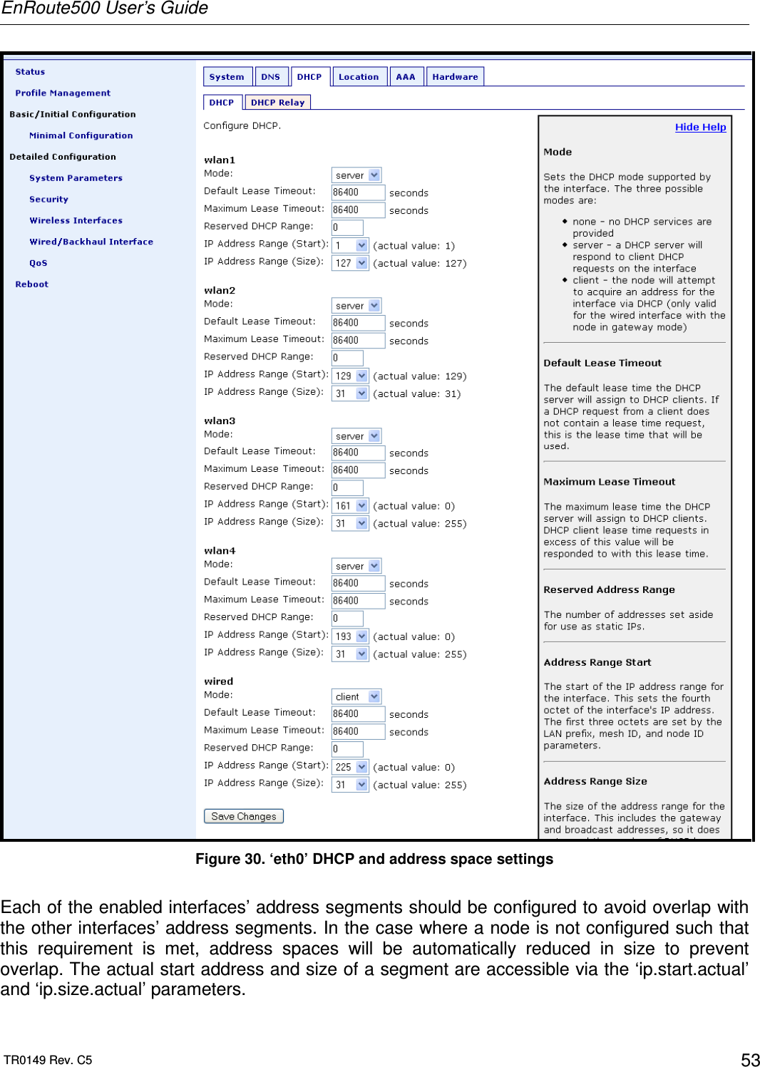
![EnRoute500 User’s Guide TR0149 Rev. C5 55 eth0.ip.netmask = 255.255.255.224 [read-only] If the local DHCP server is enabled for the Ethernet interface, addresses must be reserved for statically-configured devices by setting the ‘dhcp.reserve’ parameter in the ‘eth0’ interface. This will reserve the specified number of addresses at the bottom of the IP range for the interface. For example, if the interface has been assigned the address 10.2.4.225, the netmask 255.255.255.224, and the ‘dhcp.reserve’ value 5, the addresses 10.2.4.226 through 10.2.4.230 will be available for use by statically configured devices. The remaining addresses in the interfaces address space can be assigned by the DHCP server to other client devices. The ‘dhcp.reserve’ value can be set via the web interface using the “DHCP” sub-tab on the “DHCP” tab on the “System Parameters” page (see Figure 30). 8.2 IP Configuration for Gateway Nodes When an EnRoute500 is configured as a gateway, the Ethernet interface is used to provide backhaul capability by connecting it to a WAN or directly to the Internet. Clients cannot connect to the EnRoute500 through the Ethernet interface when operating in this mode. The Ethernet interface address can either be acquired from a DHCP server on the WAN or be set manually. Figure 31. Wired interface parameters with EnRoute500 using wired interface for backhaul 8.2.1 DHCP When configured as a gateway, the EnRoute500 can be set to obtain an obtain an address for its Ethernet interface using DHCP. To enable the DHCP client mode on the Ethernet interface,](https://usermanual.wiki/Tranzeo-Wireless-Technologies/RAEKT2KN2/User-Guide-776051-Page-55.png)