Tranzeo Wireless Technologies SQQNT623 Wireless Networking Device User Manual users manual
Tranzeo Wireless Technologies, Inc Wireless Networking Device users manual
users manual

TRANZEO TR-FDD
Revision: 1.1
Firmware: 3.2.0
Date: 06/26/07
Tranzeo TR-FDD Series
User Guide
Covers the following models:
TR-FDD-24
TR-FDD-N

iiiiii
This document is intended for Public Distribution 19473 Fraser Way,
Pitt Meadows, B.C. Canada V3Y 2V4
ii
Document Revisions:
Version 1.0 January 29, 2007
Version 1.1 June 26, 2007
Tranzeo Wireless Technologies Inc.
19473 Fraser Way
Pitt Meadows, BC
Canada V3Y 2V4
Toll Free Number: 1.866.872.6936
Technical Support: 1.888.460.6366 General Inquiries: info@tranzeo.com
Local Number: 1.604.460.6002 Sales: sales@tranzeo.com
Fax Number: 1.604.460.6005 Technical Support: support@tranzeo.com

iiiiiiiii
This document is intended for Public Distribution
19473 Fraser Way,
Pitt Meadows, B.C. Canada V3Y 2V4
Safety Information
iii
TR-FDD Series
Tranzeo Wireless Technologies
This device has been tested and found to comply with the limits for a Class B digital device
pursuant to Part 15 of the FCC rules. These limits are designed to provide reasonable
protection against harmful interference when the device is operated in a residential
environment. This device generates, uses, and can radiate radio frequency energy. If not
installed and used in accordance with the user guide, may cause harmful interference to radio
communication. In case of harmful interference, the users will be required to correct the
interference at their own expense.
The users should not modify or change this device without written approval from Tranzeo
Wireless. Modification will void warranty and authority to use the device.
For safety reasons, people should not work in a situation where RF exposure limits could be
exceeded. To prevent this situation, the users should consider the following rules:
Install the antenna so that there is a minimum of 100 cm (39.37 in) of distance between
the antenna and people.
Do not turn on power to the device while installing the antenna.
Do not connect the antenna while the device is in operation.
Do not collocate or operate the antenna used with the device in conjunction with any
other antenna or transmitter.
Use this product only with antennas of the same or lower gain as the following Tranzeo
Antennas:
TR-GD58-26 – 5.8 GHz 26 dBi Grid antenna
TR-5.8-32db-ant—5.8 GHz 32dBi Dish antenna
In order to ensure compliance with local regulations, the installer MUST enter the
antenna gain at the time of installation. See Chapter 3: Wireless Settings, for details.
FCC Compliance
Safety Information
Operation of this device is subject to the following two conditions: (1) this device may not
cause interference, and (2) this device must accept any interference, including interference
that may cause undesired operation of the device.
Industry Canada Compliance

iviviv
This document is intended for Public Distribution
19473 Fraser Way,
Pitt Meadows, B.C. Canada V3Y 2V4
Safety Information
iv
TR-FDD Series
Tranzeo Wireless Technologies
You must read and understand the following safety instructions before installing the device:
This antenna‘s grounding system must be installed according to Articles 810-15, 810
-20, 810-21 of the National Electric Code, ANSI/NFPA No. 70-1993. If you have any
questions or doubts about your antenna‘s grounding system, contact a local licensed
electrician.
Never attach the grounding wire while the device is powered.
If the ground is to be attached to an existing electrical circuit, turn off the circuit before
attaching the wire.
Use the Tranzeo Power over Ethernet (POE) adapter only with approved Tranzeo
models.
Never install radio equipment, surge suppressors or lightning protection during a storm.
! Safety Instructions
Lightning Protection
The key to lightning protection is to provide a harmless route for lightning to reach ground.
The system should not be designed to attract lightning, nor can it repel lightning. National,
state and local codes are designed to protect life, limb, and property, and must always be
obeyed. When in doubt, consult local and national electrical codes or contact an electrician or
professional trained in the design of grounding systems.
The product requires professional installation. Professional installers ensure that the
equipment is installed following local regulations and safety codes.
Professional Installation Required

vvv
This document is intended for Public Distribution
19473 Fraser Way,
Pitt Meadows, B.C. Canada V3Y 2V4
Table of Contents
v
TR-FDD Series
Tranzeo Wireless Technologies
Chapter 1: Overview ........................................................................ 1-1
Introduction ...................................................................................................... 1-1
Product Kit........................................................................................................ 1-1
Product Description .......................................................................................... 1-1
LED Panel Indicators ................................................................................... 1-2
Chapter 2: Hardware Installation ...................................................... 2-1
Getting Ready ................................................................................................... 2-1
Tools Required ............................................................................................. 2-1
Site Selection ............................................................................................... 2-1
Polarity ......................................................................................................... 2-2
Power Supply ............................................................................................... 2-2
Installing the Ethernet Cable ............................................................................ 2-3
Attaching the Channel Shield .......................................................................... 2-5
Mounting the Radio .......................................................................................... 2-6
Grounding the Antenna .................................................................................... 2-7
Connecting the Radio ....................................................................................... 2-8
Best Practices.................................................................................................... 2-9
Chapter 3: Configuration ................................................................... 3-1
Connecting to the Radio ................................................................................... 3-1
Changing the IP Address - Windows XP .................................................... 3-1
Changing the IP Address Using the Tranzeo Locator ................................. 3-2
Login into the Configuration Interface ............................................................. 3-3
Information Page .............................................................................................. 3-4
Setup Menu ....................................................................................................... 3-5
Wireless Settings ......................................................................................... 3-5
Administrative Settings ............................................................................... 3-7
Security ........................................................................................................... 3-8
Basic Security Settings .............................................................................. 3-8
Advanced Security Settings ....................................................................... 3-9
Status .............................................................................................................. 3-10
AP List ....................................................................................................... 3-11
ARP Table ................................................................................................. 3-11
Statistics ..................................................................................................... 3-12
System Performance .................................................................................. 3-14
Network Configuration ................................................................................... 3-15
Table of Contents

vivivi
This document is intended for Public Distribution
19473 Fraser Way,
Pitt Meadows, B.C. Canada V3Y 2V4
Table of Contents
vi
TR-FDD Series
Tranzeo Wireless Technologies
Static IP Mode ........................................................................................... 3-15
DHCP Client .............................................................................................. 3-16
Appendix A: Grounding and Lightning Protection Information .... A-1
Appendix B: Channel Allocations .................................................... B-1
Appendix C: Wiring Standard ........................................................... C-1
Appendix D: PxP Install Checklist .................................................... D-1
Appendix E: Glossary of Terms ....................................................... E-1
Appendix F: Tranzeo Electrical Plugs .............................................. F-1
Appendix G: Warranty Terms ........................................................... G-1
Appendix H: How Can We Improve? ................................................ H-1
Appendix I: Notes .............................................................................. I-1
111
This document is intended for Public Distribution
19473 Fraser Way,
Pitt Meadows, B.C. Canada V3Y 2V4
Chapter 1: Overview
1-1
TR-FDD Series
Tranzeo Wireless Technologies
Introduction
This next-generation wireless LAN device–the Tranzeo TR-FDD series– brings
Ethernet-like performance to the wireless realm. Fully compliant with the
IEEE802.11a standard, the TR-FDD series also provides powerful features such as
the Internet-based configuration utility as well as WEP and WPA security.
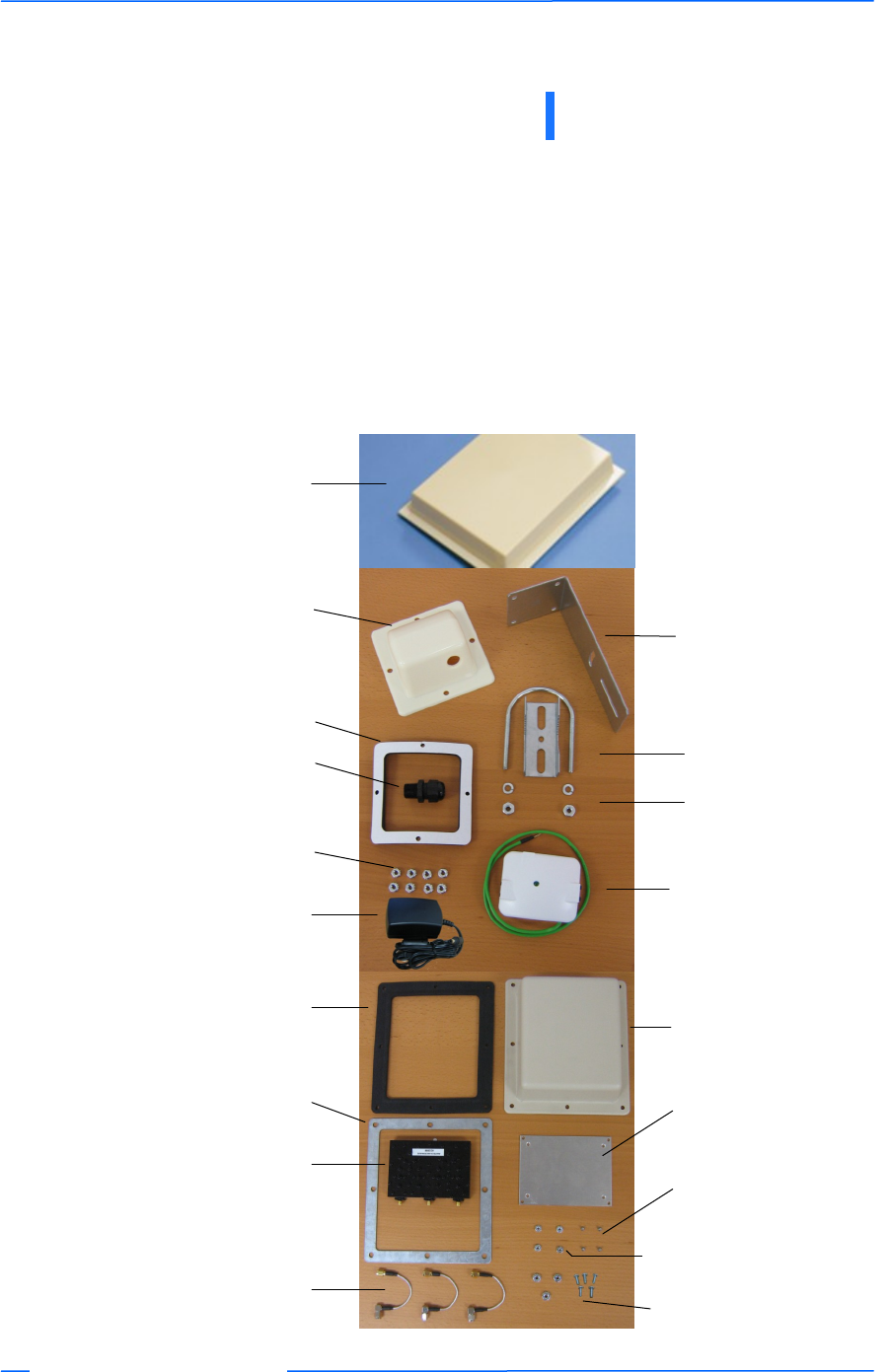
Product Kit
The TR-FDD Series product kit contains the items shown below. If any item is
missing or damaged, contact your local dealer for support.
Chapter 1: Overview
DC power adapter x 1
Kep nuts x 8
TR-FDD Series
device x 1
Ethernet boot
cover x 1
Gasket x 1
Strain relief x 1
Mounting bracket x 1
U-bolt w/ 2 nuts x 1
Lock washers x 2
POE adapter x 1
Channel Shield Gasket* x 1 Channel Shield
Cover x 1
Channel Shield
Compression Ring x 1
Channel Shield * x 1
Right Angle SMA male to
SMA male x 3
Channel Shield
Mounting Plate x 1
Channel Shield
Mounting Screws x 4
Channel Shield
Mounting Plate Nuts x 4
Channel Shield Nuts (3)
and Screws (4)
*Part of the TR-CSx Kit
222
This document is intended for Public Distribution
19473 Fraser Way,
Pitt Meadows, B.C. Canada V3Y 2V4
Chapter 1: Overview
1-2
TR-FDD Series
Tranzeo Wireless Technologies
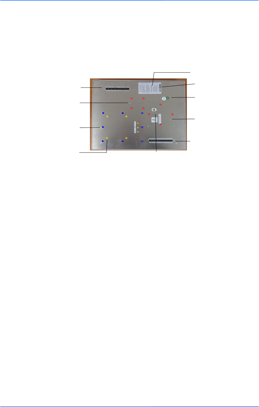
Product Description
The LEDs, ports and product information are located at the back of the TR-FDD
Series radio, as shown in the picture.
LED Panel indicators
MAC address
Ethernet port
Serial number
Studs for the boot
cover
Studs for the
mounting bracket
LED Panel indicators
Grounding Post
Attachment points for
channel shield cover
Attachment points for
channel shield

333
This document is intended for Public Distribution
19473 Fraser Way,
Pitt Meadows, B.C. Canada V3Y 2V4
Chapter 1: Overview
1-3
TR-FDD Series
Tranzeo Wireless Technologies
LED Panel Indicators
Label Color Indicators
Power ● Red On: Powered on
Off: No power
LAN ● Green
On: Ethernet link
Flashing: Ethernet traffic
Off: No Ethernet link
Radio ● Amber
On: Radio link
Flashing: Radio activity
Off: No radio link
Signal
● Red
Light up in sequence to indicate signal
strength. Green being the highest signal.
● Amber
● Green
111
This document is intended for Public Distribution
19473 Fraser Way,
Pitt Meadows, B.C. Canada V3Y 2V4
Chapter 2: Hardware Installation
2-1
TR-FDD Series
Tranzeo Wireless Technologies
The TR-FDD Series radios are easy to install, as you‘ll see in this chapter. Before
starting, you will need to get the tools listed below and decide about the site and
orientation of the device. Once ready, follow the instructions about how to install
the Ethernet cable, mount the device, ground the antenna, and make the
connections in order to get a proper installation.
Getting Ready
Tools Required
To install your TR-FDD Series radio you will need the following tools:
1/2‖ wrench x 1
3/4‖ wrench x 1
3/8” wrench x 1
Cat 5 cable stripper x 1
Cat 5 cable (to connect the radio to the POE adapter)
RJ-45 patch cable
RJ-45 crimper x 1
RJ-45 connectors x 4
#6 green grounding wire
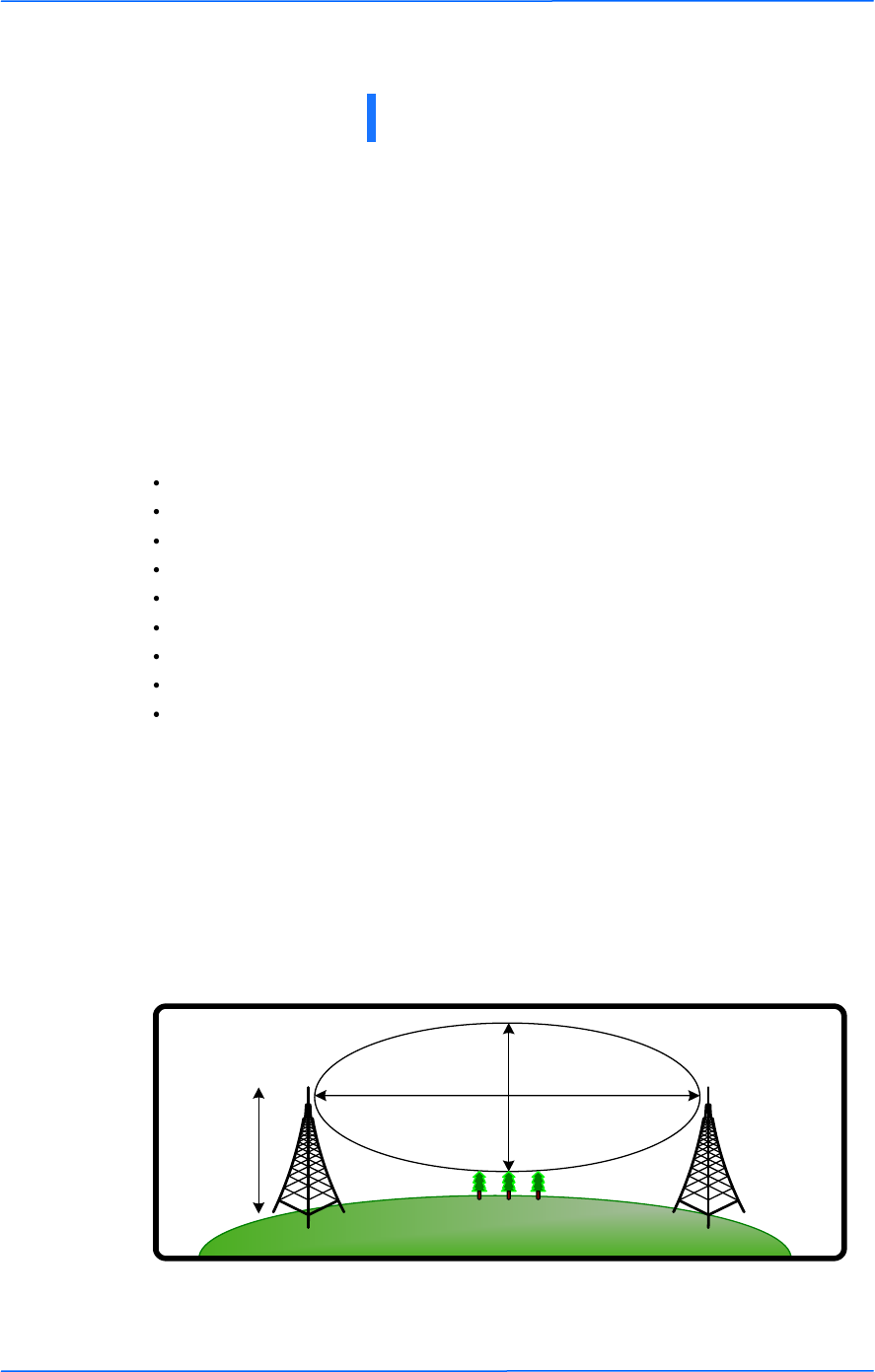
Site Selection
Determine the location of the radio before installation. Proper placement of the
device is critical to ensure optimum radio range and performance. You should
perform a site survey to determine the optimal location.
Ensure the CPE is within line-of-sight of the access point. The line-of-sight is an
ellipse, called the Fresnel zone. This zone should be clear of obstacles since
obstructions will impede performance of the device.
Fresnel zone
Chapter 2: Hardware Installation
Antenna
Height
r = radius
d = distance

222
This document is intended for Public Distribution
19473 Fraser Way,
Pitt Meadows, B.C. Canada V3Y 2V4
Chapter 2: Hardware Installation
2-2
TR-FDD Series
Tranzeo Wireless Technologies
Polarity
Determine if the antenna‘s polarization will be horizontal or vertical before
installation. The TR-FDD radios can be used in either polarity. The Ethernet boot
cover should always be placed so that the cable runs toward the ground for
maximum environmental protection.
Power Supply
Only use a power adapter approved for use with the TR-FDD Series radio.
Otherwise, the product may be damaged and will not be covered by the Tranzeo
warranty.
333
This document is intended for Public Distribution
19473 Fraser Way,
Pitt Meadows, B.C. Canada V3Y 2V4
Chapter 2: Hardware Installation
2-3
TR-FDD Series
Tranzeo Wireless Technologies
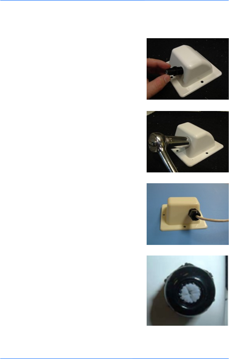
Installing the Ethernet Cable
Step 2:
Using a 3/4‖ wrench, tighten the strain
relief until it touches the boot cover.
IMPORTANT! Use hand tools only. Do
not over tighten.
Step 3:
Put the cap nut back over the strain relief
and insert the Cat 5 cable through it. Wire
the cable following the EIA/TIA T568B
standard, and attach the RJ-45 connectors
to each end of the cable. (See Appendix F:
Wiring Standard).
Step 1:
Insert the strain relief, without the cap nut,
into the port opening of the boot cover.
Step 4:
If you purchased the device with a dual
port cover, repeat steps 1, 2, and 3 for the
second port.
IMPORTANT! If you are not going to use
the second port, insert the strain relief into
the boot cover and tighten the cap nut to
ensure a weather-tight seal, as shown in
the picture.
444
This document is intended for Public Distribution
19473 Fraser Way,
Pitt Meadows, B.C. Canada V3Y 2V4
Chapter 2: Hardware Installation
2-4
TR-FDD Series
Tranzeo Wireless Technologies
Step 7:
Fit the boot cover over the 4 studs and the
gasket. Secure with 4 keps nuts. Tighten
with a 3/8‖ wrench until the gasket is at
least 50% compressed.
Step 5:
Place the gasket—with the adhesive side
facing up—over the 4 studs around the port
of the radio. Flatten the gasket ensuring
there are no gaps. Remove the backing.
Step 8:
Make sure the cap nut of the strain relief is
tightened properly to ensure a weather-
proof seal.
IMPORTANT! Hand tighten only. Do not
over tighten as you may damage the
weather-tight seal of the strain relief.
Step 6:
Plug the Cat 5 cable inserted in the boot
cover into the port. Remember to place the
boot cover according to the desired
polarization, so that the strain relief faces
the ground.
555
This document is intended for Public Distribution
19473 Fraser Way,
Pitt Meadows, B.C. Canada V3Y 2V4
Chapter 2: Hardware Installation
2-5
TR-FDD Series
Tranzeo Wireless Technologies
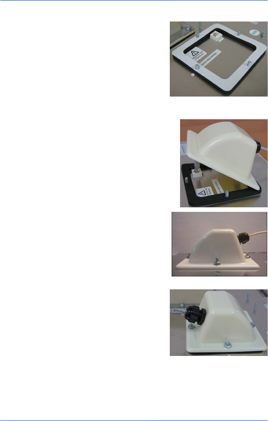
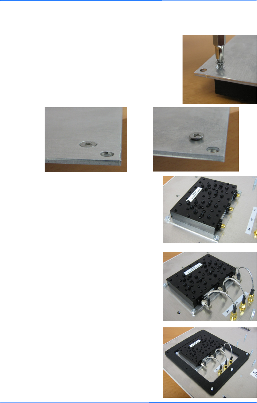
Step 9:
Attach Channel shield to the channel shield
mounting plate.
The screws should fit in the counter sunk
holes.
Correct
Incorrect
Step 10:
Attach Channel shield mounting plate to
the TR-FDD with the included nuts.
Step 11:
Attach right angle SMA to SMA male
cables as shown between the channel shield
and the TR-FDD.
Step 12:
Place the Channel shield gasket as shown.
Attaching the Channel Shield
666
This document is intended for Public Distribution
19473 Fraser Way,
Pitt Meadows, B.C. Canada V3Y 2V4
Chapter 2: Hardware Installation
2-6
TR-FDD Series
Tranzeo Wireless Technologies
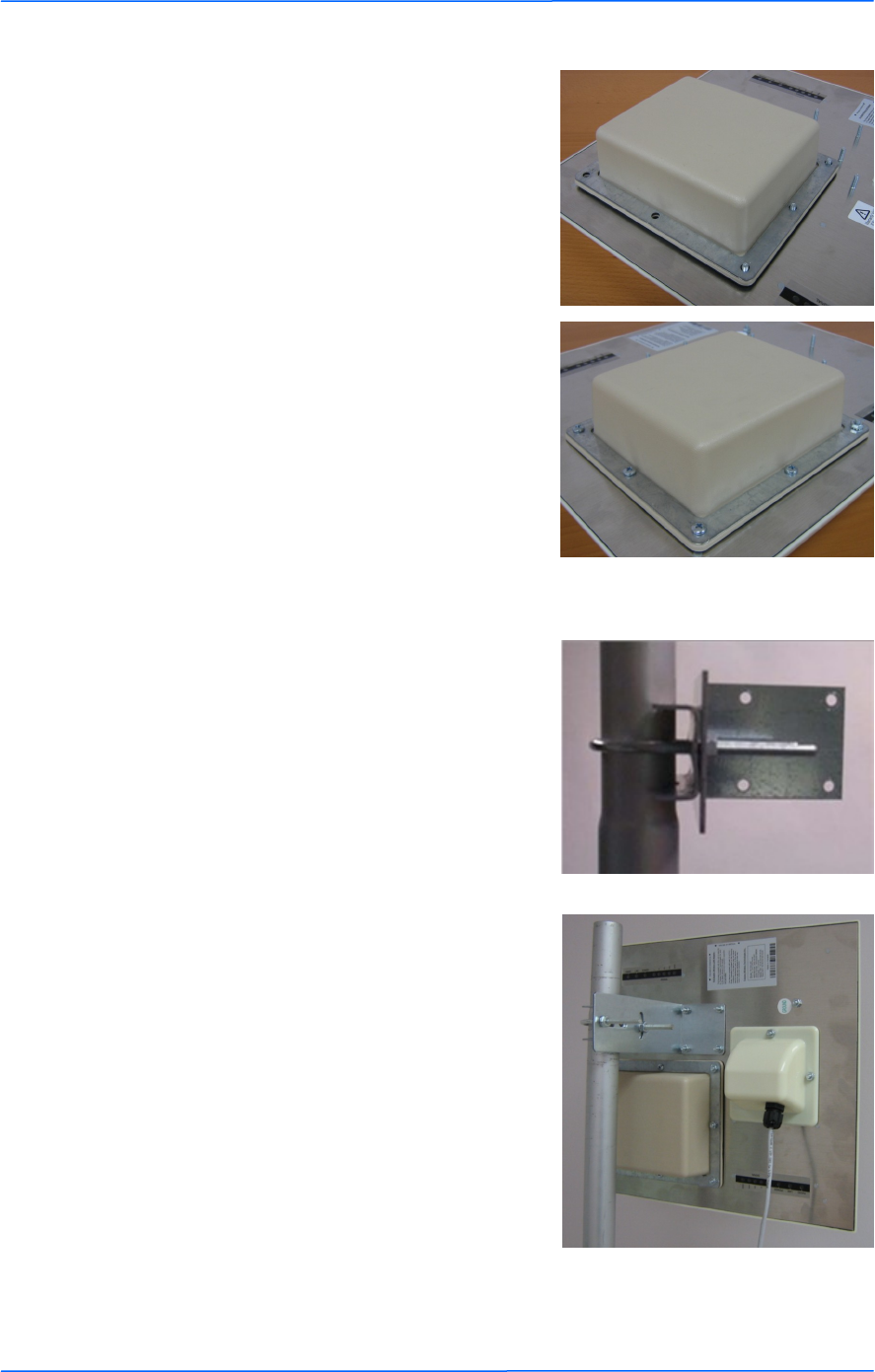
Step 13:
Place the channel shield cover and channel
shield compression ring over the channel
shield as shown.
Step 14:
Attach and tighten the screws and nuts as
shown ensuring that the gasket is
compressed equally around the cover.
Step 15:
Attach the mounting bracket to the pole
using the U-bolt. Secure the U-bolt with
the lock washers and the nuts. Align if
necessary, and then tighten the nuts enough
to prevent any movement.
Step 16:
Fit the radio to the mounting bracket.
Secure the radio with kep nuts.
IMPORTANT! The strain relief must be
always facing the ground.
Mounting the Radio
777
This document is intended for Public Distribution
19473 Fraser Way,
Pitt Meadows, B.C. Canada V3Y 2V4
Chapter 2: Hardware Installation
2-7
TR-FDD Series
Tranzeo Wireless Technologies
Grounding the Antenna
Step 17:
Using a #6 green grounding wire, connect
the grounding lug on the radio to a proper
ground. See Appendix A: Grounding and
Lighting Protection Information.
IMPORTANT: This device must be grounded. Connect the green grounding wire
to a known good earth ground, as outlined in the National Electrical Code. See
Appendix A: Grounding and Lightning Protection Information for details.
!
888
This document is intended for Public Distribution
19473 Fraser Way,
Pitt Meadows, B.C. Canada V3Y 2V4
Chapter 2: Hardware Installation
2-8
TR-FDD Series
Tranzeo Wireless Technologies
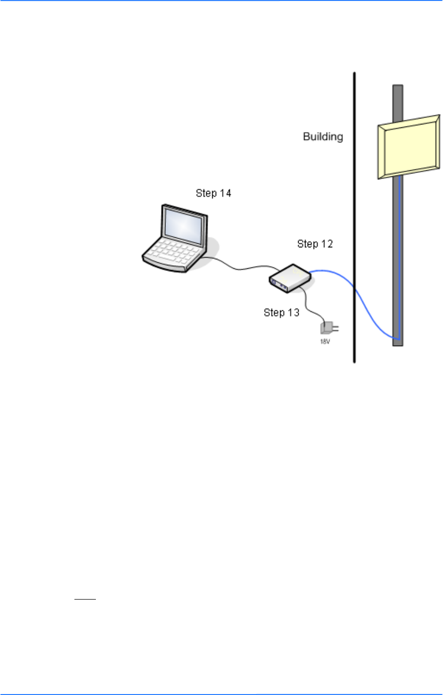
Connecting the Radio
Step 14:
To configure the TR-FDD Series radio,
connect the Ethernet cable to the POE
adapter and to a computer. Ensure that the
distance between the computer and the
radio does not exceed 300 ft (90 m).
Note: If connecting to a hub or switch, a
crossover cable may be required.
IMPORTANT! Use the power adapter
supplied with the radio. Otherwise, it may
be damaged.
Step 12:
Connect the Cat 5 cable from the radio into
the RJ-45 jack marked ―CPE‖ on the POE
adapter. The POE adapter is not weather-
proof and should be installed indoors.
Step 13:
Connect the power adapter to the POE
adapter and plug the other end to an outlet.
The POE adapter will be powered on and
the power indicator on the top panel will
turn on. We recommend connecting the
power adapter to an outlet with surge
suppression capability with an uninterrupted
power supply (UPS) for reduced outages.

999
This document is intended for Public Distribution
19473 Fraser Way,
Pitt Meadows, B.C. Canada V3Y 2V4
Chapter 2: Hardware Installation
2-9
TR-FDD Series
Tranzeo Wireless Technologies
Best Practices
Follow these practices to ensure a correct installation and grounding.
Always try to run long Cat 5 and LMR cables inside of the mounting pole.
This helps to insulate the cable from any air surges.
Keep all runs as straight as possible. Never put a loop into the cables.
Test all grounds to ensure that you are using a proper ground. If using an
electrical socket for ground, use a socket tester, such as Radio Shack 22-141.
Keep a copy of the National Electrical Code Guide at hand and follow its
recommendations.
If you are in doubt about the grounding at the location, drive your own rod
and bond it to the house ground. At least you will know that one rod is
correct in the system.
111
This document is intended for Public Distribution
19473 Fraser Way,
Pitt Meadows, B.C. Canada V3Y 2V4
Chapter 3: Configuration
3-1
TR-FDD Series
Tranzeo Wireless Technologies
The TR-FDD Series radios can be configured through an HTML configuration
interface, accessible using any Internet browser. The configuration interface
allows you to define and change settings, and also shows information about the
performance of the device.
In this chapter we‘ll cover how to access the configuration interface, configure the
TR-FDD Series radio, and interpret the information displayed in the interface.
Depending on whether the device is defined as an AP or CPE (infrastructure
station), some menu options, windows, and fields in the interface may vary or may
not appear at all. We‘ll indicate so when describing each window.
Connecting to the Radio
Before accessing the configuration interface, you have to change the network
connection settings in your computer to be on the same subnet as the radio.
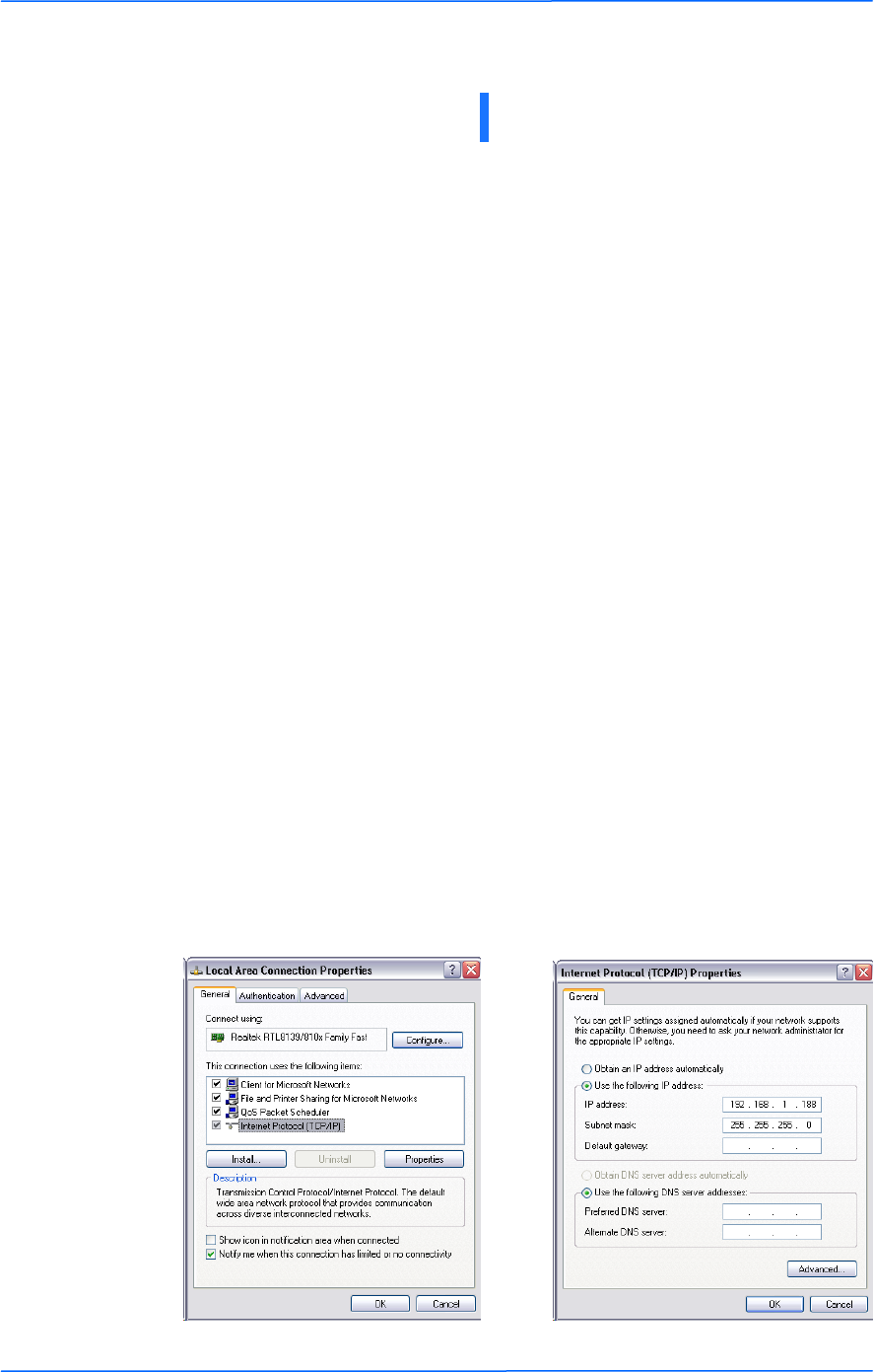
Changing the IP Address - Windows XP
1. In your computer, open Control Panel > Network Connections > Local Area
Connection.
2. In Local Area Connection Status > General, click Properties.
3. In Local Area Connection Properties > General, select Internet Protocol
(TCP/IP) and click Properties.
4. In Internet Protocol (TCP/IP) Properties > General, select Use the following
IP address.
5. Enter your IP address and Subnet Mask. The default IP address of the radio
is 192.168.1.100, which cannot be used here.
6. Click OK and Close.
Chapter 3: Configuration
222
This document is intended for Public Distribution
19473 Fraser Way,
Pitt Meadows, B.C. Canada V3Y 2V4
Chapter 3: Configuration
3-2
TR-FDD Series
Tranzeo Wireless Technologies
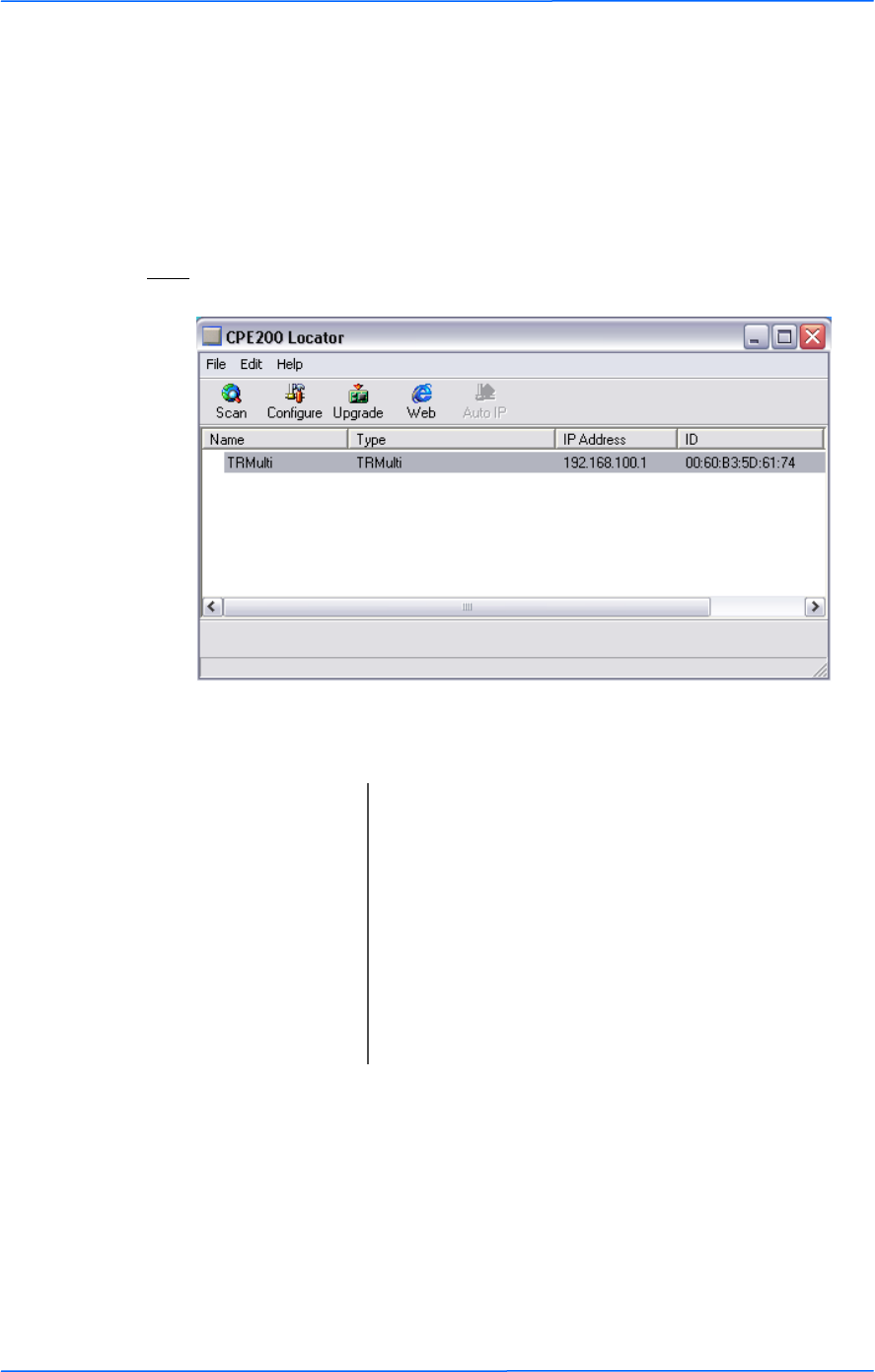
Changing the IP Address Using the Tranzeo Locator
The Tranzeo Locator is a utility that allows users to quickly change the IP address
of the Tranzeo radios. It sends out a broadcast on the network and displays a list of
other Tranzeo radios connected, from which you can configure the IP address for
your device.
Note: The Locator cannot locate radios through routers.
The Tranzeo Locator displays the following options:
Find the latest version of the Tranzeo Locator at www.tranzeo.com, under Tranzeo
Support > Support Files > Radio Utilities.
Scan: Locates Tranzeo radios connected to the network. A
yellow icon appears before the name when the radio is
not in the same subnet.
Configure: Used to set a static IP address or set the radio into
DHCP mode.
Upgrade: Under development.
Web: Opens a browser to access the configuration interface.
Auto IP: To automatically set the radio to an IP address one
number higher than the IP address of the computer.
333
This document is intended for Public Distribution
19473 Fraser Way,
Pitt Meadows, B.C. Canada V3Y 2V4
Chapter 3: Configuration
3-3
TR-FDD Series
Tranzeo Wireless Technologies
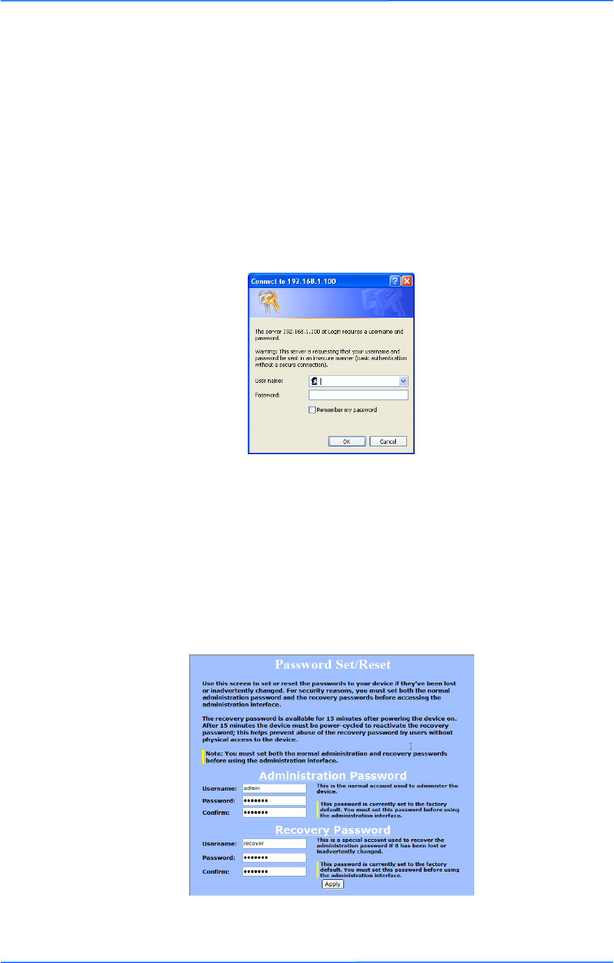
Login into the Configuration Interface
After defining the network settings, follow these steps to login into the Tranzeo
Configuration Interface.
1. Open your Internet browser (Internet Explorer, Netscape, or Firefox).
2. In the address bar, type your IP address (default IP: http://192.168.1.100).
3. In the login dialog, enter your Username and Password (if you‘re a first-
time user, follow the instructions below).
4. Click OK. You will then access the configuration interface.
If you‘re a first-time user:
1. Enter the default username admin and the default password default.
2. You will be prompted to enter your new username and password in the login
dialog. You will then access the configuration interface.
3. In the Password Set/Reset window, change the Administration and
Recovery* passwords. They cannot be left as default and must be different
from each other. You can change the usernames too.
4. Click Apply to save the changes.
* The recovery username and password are used to access the Password Set/Reset
window if the administration password is lost.
444
This document is intended for Public Distribution
19473 Fraser Way,
Pitt Meadows, B.C. Canada V3Y 2V4
Chapter 3: Configuration
3-4
TR-FDD Series
Tranzeo Wireless Technologies
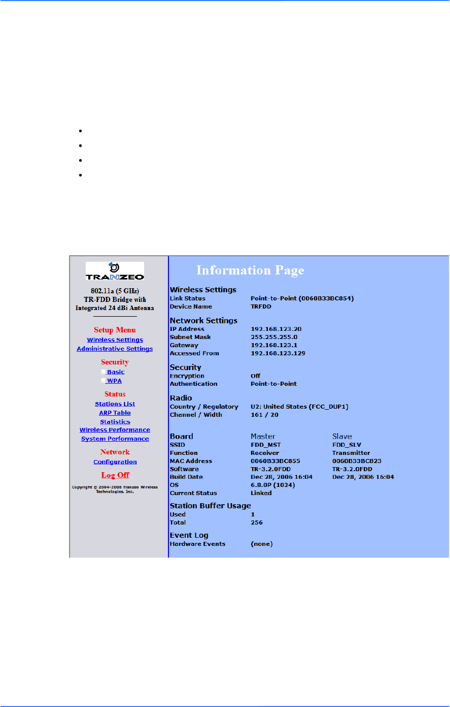
Information Page
This is the first window of the configuration interface. It shows the main menu and
information about the device settings, like wireless, network, and security settings.
The menu is divided in four sections:
Setup Menu
Security
Status
Network
Each section contains navigation links to the configuration windows.
Information Page
555
This document is intended for Public Distribution
19473 Fraser Way,
Pitt Meadows, B.C. Canada V3Y 2V4
Chapter 3: Configuration
3-5
TR-FDD Series
Tranzeo Wireless Technologies
Setup Menu
In this section you would be able to configure wireless and administrative settings
for the TR-FDD Series radio.
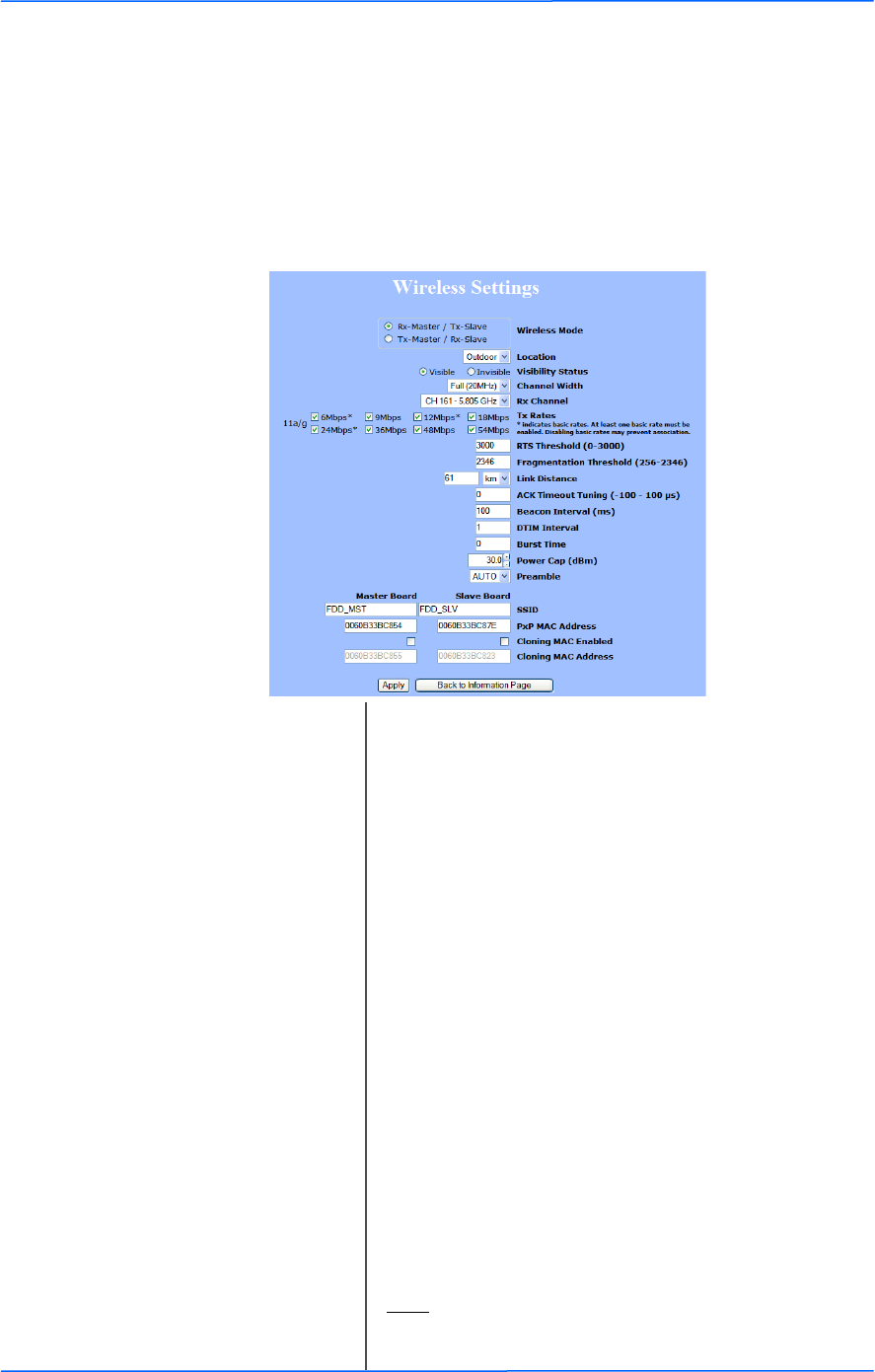
Wireless Settings
This window displays the wireless configuration of the device.
.
Wireless Mode: Rx-Master / Tx-Slave or Tx-Master / Rx-Slave. One
radio of the pair needs to be set to Rx-Master / Tx-
Slave and the other radio of the pair needs to be set to
Tx-Master / Rx-Slave.
SSID: The Service Set Identifier (SSID) is the name that
identifies a specific wireless LAN. Devices must have
the same SSID to communicate with each other. The
Master Board SSID must be set the same as the Master
Board SSID on the peer radio. The Slave Board SSID
also needs to be set to the same as the Slave Board
SSID on the peer radio.
Visibility Status: You can set your access point to be Visible or
Invisible to clients.
Location: You can set the location of the radio to be Outdoor or
Indoor. The available channels may differ depending
on the location.
Channel: Select the channel that matches the channel filter you
are using with the radios.
TX Rate: The transmission speed at which the radio and access
point communicate with each other. Basic rates must
be selected.
Note: Setting this rate below the maximum possible
does not limit bandwidth and often has a negative
impact on the operation of your network.

666
This document is intended for Public Distribution
19473 Fraser Way,
Pitt Meadows, B.C. Canada V3Y 2V4
Chapter 3: Configuration
3-6
TR-FDD Series
Tranzeo Wireless Technologies
Link Distance: This is the distance between the two TR-FDD radios.
This setting is necessary to define the correct ACK
timing. Setting this value too low or too high will
result in low throughput and high retries.
ACK Timeout Tuning: The time that the radio waits for an acknowledgment
(ACK) from the access point accepting transmission
before re-attempting to send the data. This is an offset
from the ACK timing set by the link distance.
Beacon Interval: This is the rate at which the access point broadcasts its
beacons.
DTIM Interval*: The DTIM interval (Delivery Traffic Indication
Message) helps to keep marginal clients connected by
sending wake up frames.
Burst Time: This allows to send data without stopping. Note that
other wireless devices in the network will not be able
to transmit data for this number of microseconds.
Power Cap: It is the maximum output power of the radio.
Antenna Gain: Select the gain of the antenna. This information must
be set by the installer at the time of installation.(1)
Preamble: Select type: Long uses long preamble only, Auto
(recommended) tries short preamble first, then long.
PxP MAC Address: The Master Board PxP MAC Address must be set to
the Master Board PxP MAC Address on the peer radio.
The Slave Board PxP MAC Address must be set to the
peer radio Slave Board MAC Address.
RTS Threshold: This is the maximum size for a packet to be sent
automatically. When it exceeds the RTS threshold, the
CPE sends first a ‗request to send‘ (RTS) to the access
point before sending the packet.
Note: The more clients you have, the lower the value
should be set.
Fragmentation
Threshold:
This is the size at which packets are fragmented in
order to be transmitted. Setting this value too low
decreases the amount sent on each transmission. In
noisy areas, this can improve performance. However,
in quiet areas, this will decrease throughput.
777
This document is intended for Public Distribution
19473 Fraser Way,
Pitt Meadows, B.C. Canada V3Y 2V4
Chapter 3: Configuration
3-7
TR-FDD Series
Tranzeo Wireless Technologies
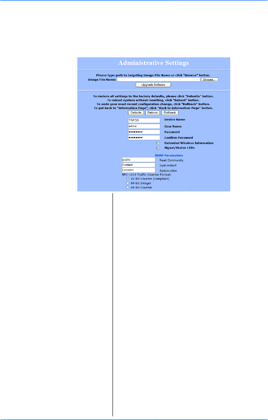
Administrative Settings
Use this window to upgrade the software, change your password, and define
SNMP parameters.
Upgrade Software: Enter the location of the software update file or
Browse to locate it in your computer. Click Upgrade
Software. If the radio does not refresh the Information
Page after 1 minute, press Refresh, Reload or F5.
Verify the new firmware is installed correctly.
Defaults: Returns all settings to factory defaults, including
passwords.
Reboot: Restarts the system without changing settings.
Rollback: To undo the most recent change.
Device Name: It is the network name of the device. This name
appears in the Locator and on the Tranzeo stations list.
User Name: This is the login username.
Password: Enter a new password if you want to change it.
Confirm Password: Re-type the new password.
Extended Wireless
Information:
Enables extended information (name and IP address),
which is only displayed with Tranzeo access points.
Signal/Status LEDs: Un-check to turn off the LED panel indicators.
SNMP Parameters: Here you set the Read Community string and
Contact/Location information. It‘s highly
recommended that you change the Read Community
string immediately to prevent unauthorized scanning
of your network.
You can also select the traffic counter format that you
would like to use.
888
This document is intended for Public Distribution
19473 Fraser Way,
Pitt Meadows, B.C. Canada V3Y 2V4
Chapter 3: Configuration
3-8
TR-FDD Series
Tranzeo Wireless Technologies
Security
In this section you can configure both basic and advanced security settings for
your device.
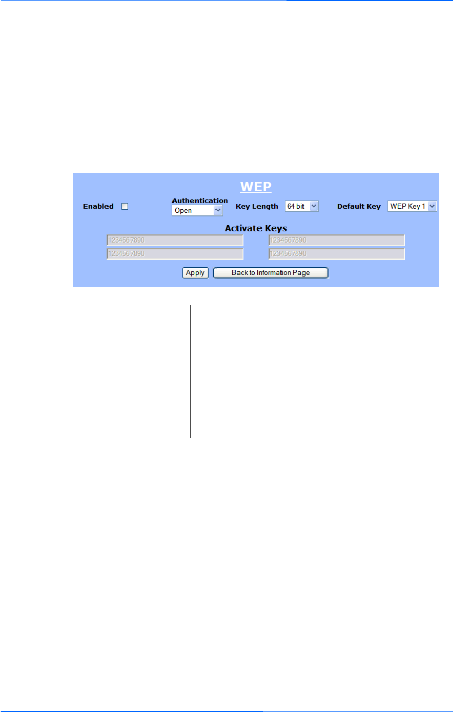
Basic Security Settings
In this window you can define WEP parameters. WEP provides security by
encrypting data so that it‘s protected when transmitted from one point to another.
Enabled: Check to turn on WEP security protocol.
Authentication: Select your system to be open or shared. Open is
always recommended.
Key Length: This is the level of encryption. Note that 64 bit is
referred to as 40 bit on some systems.
Default Key: Select the default WEP key from the list.
Activate Keys: Enter the four WEP keys you want to activate. Keys
must be entered in HEX only.
999
This document is intended for Public Distribution
19473 Fraser Way,
Pitt Meadows, B.C. Canada V3Y 2V4
Chapter 3: Configuration
3-9
TR-FDD Series
Tranzeo Wireless Technologies
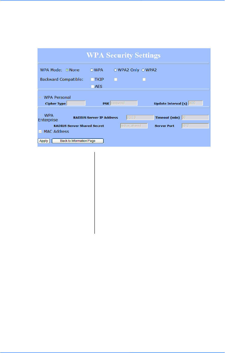
Advanced Security Settings
In this window you can enter WPA parameters. WPA provides a higher level of
security, enhancing the security features of WEP.
WPA Mode: Select the WPA mode.
Backward Compatible: Select TKIP or AES backwards compatibility if
required.
Cipher Type: Select the level of encryption.
PSK: Enter your PSK password.
Update Interval: This is the interval at which the PSK password will be
updated.
WPA Enterprise: Ensures that only authorized network users can access
the network. Enter the information about the RADIUS
server from your Internet Service Provider.
101010
This document is intended for Public Distribution
19473 Fraser Way,
Pitt Meadows, B.C. Canada V3Y 2V4
Chapter 3: Configuration
3-10
TR-FDD Series
Tranzeo Wireless Technologies
Status
This section displays information about the status and performance of your radio.
Most options and information cannot be modified in this section.
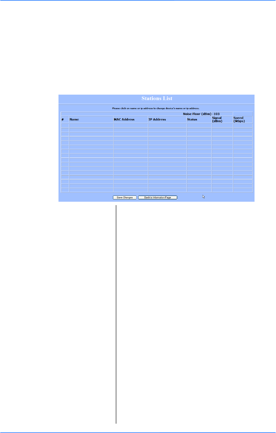
Stations List (Rx-Master / Tx-Slave Only)
This window displays a list of the stations associated with the access point and
their connection statistics.
Name: This information appears here when the device is a
Tranzeo 6000 and the Extended Wireless
Information option in the Administrative Settings
window is checked. Otherwise, the field will be blank.
You can manually enter a name by left clicking on the
field and typing in. However, if the Extended
Wireless Information option is turned on at the
client, the name you entered will be overwritten with
the name on the client.
Mac Address: The Mac addresses of the associated stations.
IP Address: Works as with the Name. It appears when the
Extended Wireless Information option in the
Administrative Settings window is checked.
Status: Indicates if the station is associated.
Signal: This is the radio frequency power in dBm as detected
at the access point. A strong link is defined by both the
AP signal and the client signal. Links should also be at
least 10 dB higher than the receive sensitivity of the
weakest element or the noise floor, whichever is
higher, on both sides.
Speed: This is the radio speed of the link. Speed is based on
both signal strength and the quality of the link. If the
link is losing a lot of packets due to poor Fresnel zones
or interference, the speed will be lower than the
strength can support.
111111
This document is intended for Public Distribution
19473 Fraser Way,
Pitt Meadows, B.C. Canada V3Y 2V4
Chapter 3: Configuration
3-11
TR-FDD Series
Tranzeo Wireless Technologies
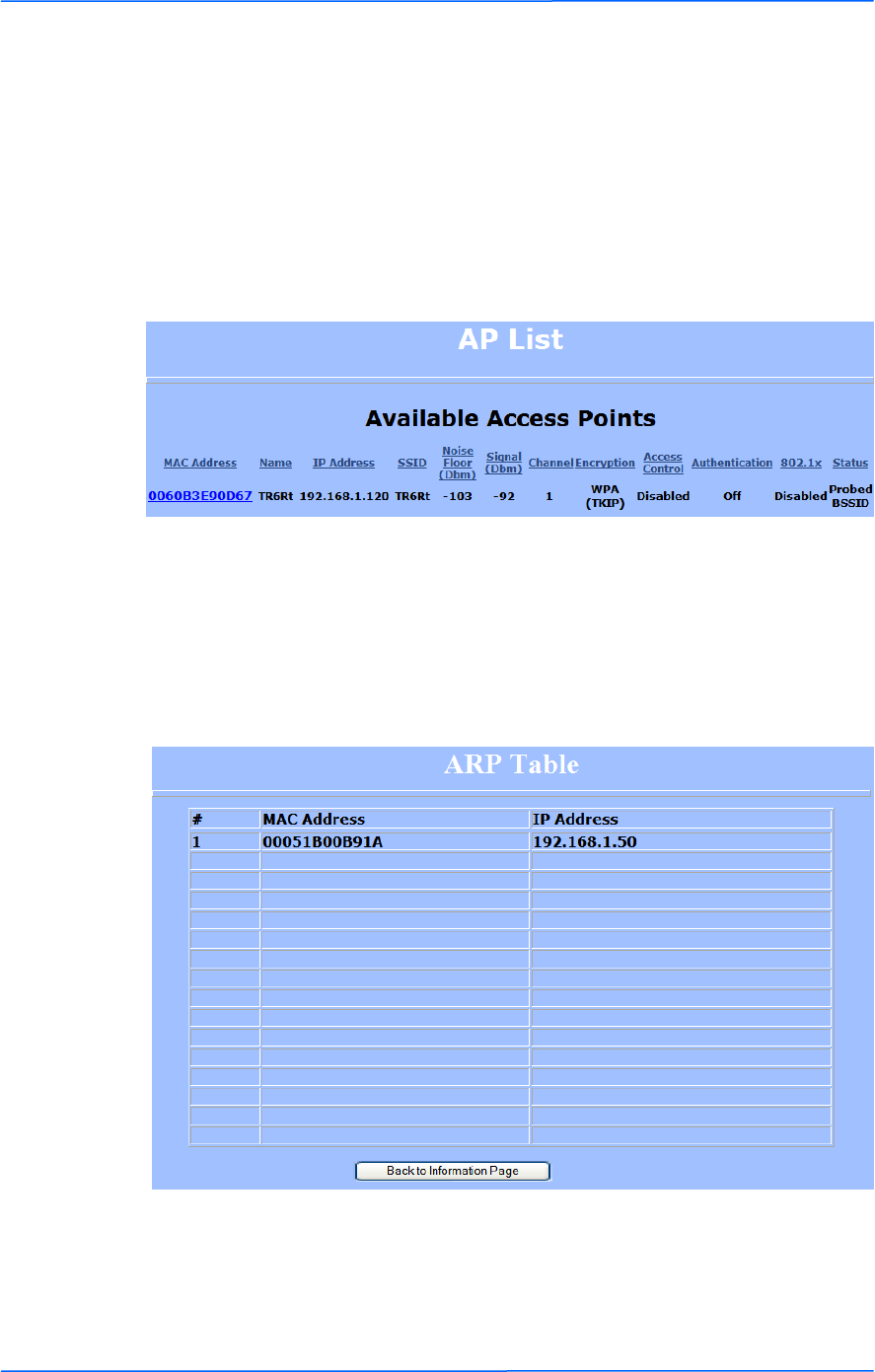
AP List (Tx-Master / Rx-Slave only)
This window displays information about the access points associated with the CPE
and the connection statistics.
You can set an access point‘s SSID as your primary SSID by clicking on the MAC
address when it‘s displayed as a link. This will automatically reboot the radio.
ARP Table
This table lists the devices that have communicated with your device via TCP.
There should be a limited number of entries in this table, especially if the
interstation blocking is turned on at the access point.
121212
This document is intended for Public Distribution
19473 Fraser Way,
Pitt Meadows, B.C. Canada V3Y 2V4
Chapter 3: Configuration
3-12
TR-FDD Series
Tranzeo Wireless Technologies
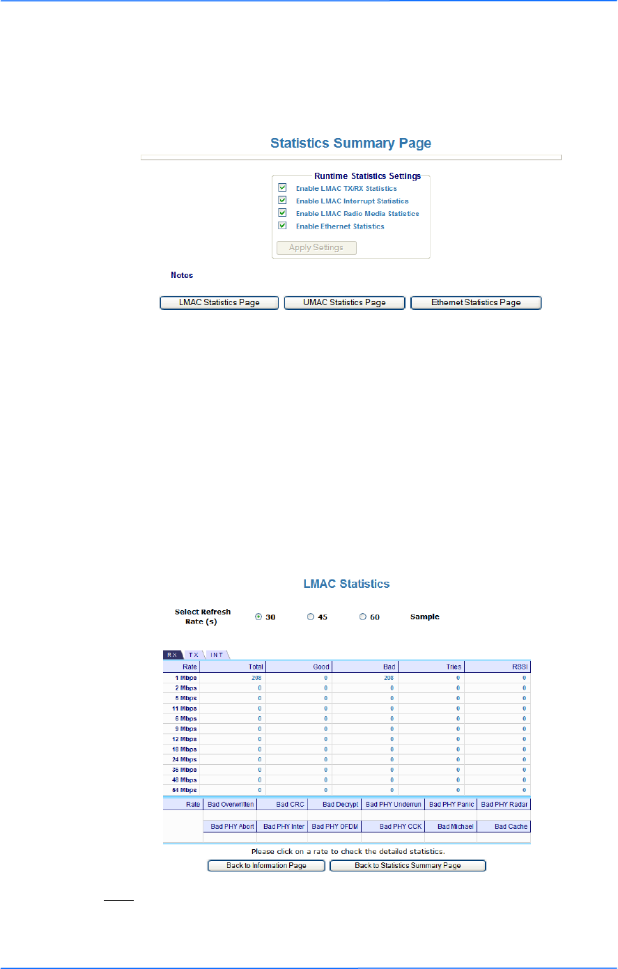
Statistics
This section is divided in 3 windows: LMAC (Lower Mac), UMAC (Upper Mac),
and Ethernet, which can be accessed from the Statistic Summary Page.
LMAC Statistics
The LMAC functions occur in the radio chipset. While the UMAC divides the
statistics into clean and failed packets, LMAC defines why packets failed.
This window contains three tabs: TX, RX and INT. TX and RX values are useful
to ISPs and other users. The INT (internal) statistics are intended for use by
Tranzeo Wireless Technical Support.
You can click onto each speed level and see how the traffic breaks down. In the
TX statistics, there should little to no Tries at Series 2, 3 or 4. The radio will try to
send a packet 4 times at Series 1 and then will try the next series 4 times. In the
RX statistics, you should look for bad CRCs and bad decrypts for signs of RF
interference or Fresnel interference links. Bad PHYs generally are caused when
the radio is unable to decode the packets due to noise.
Note:
Communication between access points and CPEs always occurs at the lowest rate.
In a normal link, you should see a fair number of transactions at the lowest rate.
131313
This document is intended for Public Distribution
19473 Fraser Way,
Pitt Meadows, B.C. Canada V3Y 2V4
Chapter 3: Configuration
3-13
TR-FDD Series
Tranzeo Wireless Technologies
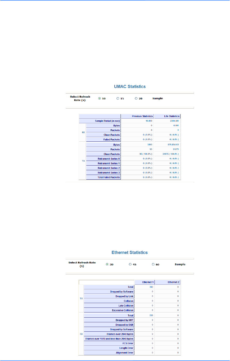
UMAC Statistics
The UMAC functions occur in the unit‘s processor. The UMAC statistics are
likely the most useful for radio troubleshooting. This window breaks down the
statistics into clean and failed packets.
The failed packets should be less than 10% in a normal operating environment. In
the TX statistics, there should be little to no Retransmits at Series 2, 3 or 4. Life
Statistics are reset on each reboot.
Ethernet Statistics
In this window, excessive collisions are usually a sign that the radio and the device
it is linked to are not on the same duplex settings. One is at full while the other is
at half. Try locking both to the same values.
Collisions do normally occur on an Ethernet network and are generally handled by
the Carrier Sense Multiple Access with Collision Detect (CSMA/CD) mechanism.
Alignment, length and excessive FCS errors could the result of a bad radio link, or
a bad Ethernet cable.
141414
This document is intended for Public Distribution
19473 Fraser Way,
Pitt Meadows, B.C. Canada V3Y 2V4
Chapter 3: Configuration
3-14
TR-FDD Series
Tranzeo Wireless Technologies
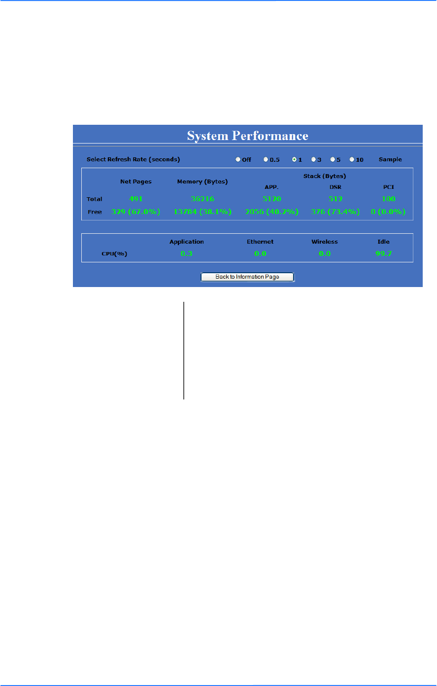
System Performance
This window shows information about the memory usage and the CPU. Many
browsers do not allow infinite refreshes of a page through scripts, so this window
may stop updating. If it does, simply change the refresh rate to another value to
restart the process.
Select Refresh Rate: Set the time for automatic refreshes.
Net Pages: This is the memory used for data transmission
Memory: This is the total memory of the system.
Stack: This section displays the memory used and available
for each stack: App. (applications), DSR, and PCI.
This information is relevant for programmers.
151515
This document is intended for Public Distribution
19473 Fraser Way,
Pitt Meadows, B.C. Canada V3Y 2V4
Chapter 3: Configuration
3-15
TR-FDD Series
Tranzeo Wireless Technologies
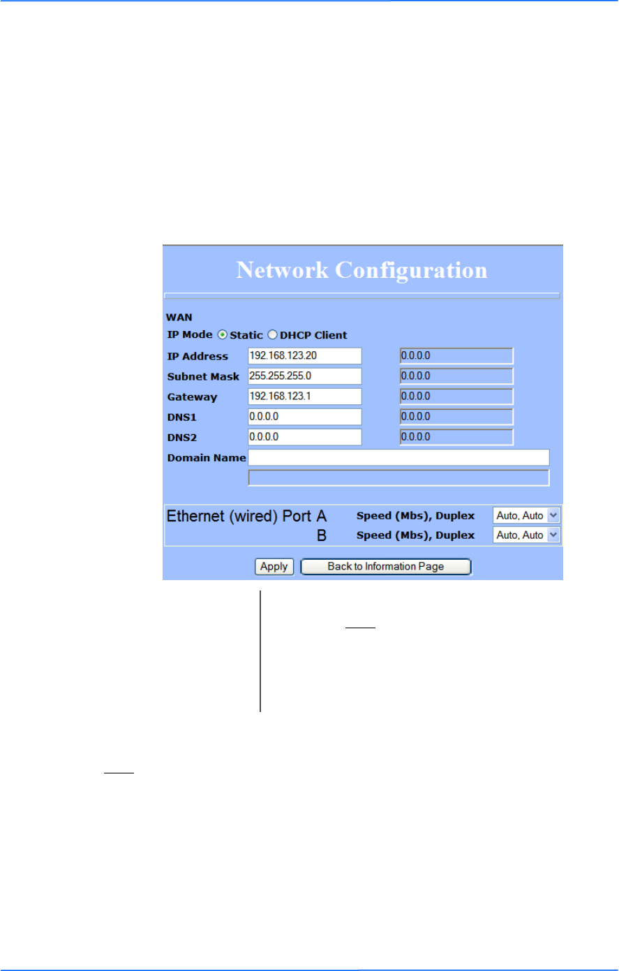
Network Configuration
In this window you can control the network configuration of the device. First, you
must define if your radio will operate with a static IP address or a DHCP address.
The content of the window varies depending on your selection.
When changing modes, the radio may need to reboot before certain features
become available.
Static IP
Note:
Many Ethernet devices do not auto-negotiate properly. If you see large numbers of
dropped pings, you may have collisions. Try locking the device at 10/half as a
troubleshooting step. If the packet losses stop, step up to 100/full. If the device the
radio is connecting cannot support 100/full, you should replace the device or place
a switch in line.
IP Mode: You can select to use Static IP or DHCP Client
(dynamic). Note: If a DHCP server is not available, the
device will try to get an IP. If has no success, it will
use a fallback IP address. The fallback IP is the
address that is set in the static address fields.
Ethernet Port Speed: Set as Auto by default.
161616
This document is intended for Public Distribution
19473 Fraser Way,
Pitt Meadows, B.C. Canada V3Y 2V4
Chapter 3: Configuration
3-16
TR-FDD Series
Tranzeo Wireless Technologies
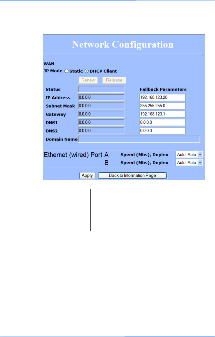
DHCP CLIENT
Note:
Many Ethernet devices do not auto-negotiate properly. If you see large numbers of
dropped pings, you may have collisions. Try locking the device at 10/half as a
troubleshooting step. If the packet losses stop, step up to 100/full. If the device the
radio is connecting cannot support 100/full, you should replace the device or place
a switch in line.
IP Mode: You can select to use Static IP or DHCP Client
(dynamic). Note: If a DHCP server is not available, the
device will try to get an IP. If has no success, it will
use a fallback IP address. The fallback IP is the
address that is set in the static address fields.
Ethernet Port Speed: Set as Auto by default.

111
This document is intended for Public Distribution
19473 Fraser Way,
Pitt Meadows, B.C. Canada V3Y 2V4
Appendix A
A-1
TR-FDD Series
Tranzeo Wireless Technologies
What is a proper ground?
This antenna must be grounded to a proper earth ground. According to the
National Electrical Code Sections 810-15s and 810-21, the grounding conductor
shall be connected to the nearest accessible locations of the following:
The building or structure grounding electrode
The grounded interior metal water piping system
The power service accessible means external to enclosure
The metallic power service raceway
The service equipment enclosure
The grounding electrode conductor
Why is coiling the LMR or Cat 5 bad?
The myth is that lighting follows the path of least resistance. It actually follows the
path of least impedance. Coiling cables creates an air-wound transformer, which
lowers the impedance. This means you are in fact making your radios a more
appealing target for surges.
What standard does Tranzeo Wireless equipment meet?
This radio exceeds International Standard IEC 61000-4-5 when properly
grounded. For a copy of the full testing report, see Report Number TRL090904 -
Tranzeo Surge Protection board located on the Tranzeo website
(www.tranzeo.com).
Is lightning damage covered by the warranty?
No. Lightning is not covered by the warranty. If you follow the instructions, your
chances of lightning damage are greatly reduced, but nothing can protect a radio
from a direct lightning strike.
Appendix A: Grounding and Lightning
Protection Information
222
This document is intended for Public Distribution
19473 Fraser Way,
Pitt Meadows, B.C. Canada V3Y 2V4
Appendix A
A-2
TR-FDD Series
Tranzeo Wireless Technologies
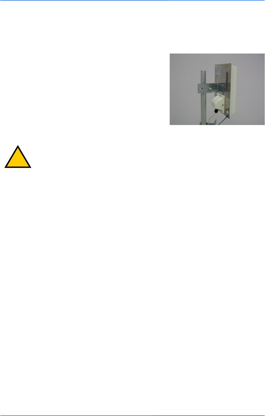
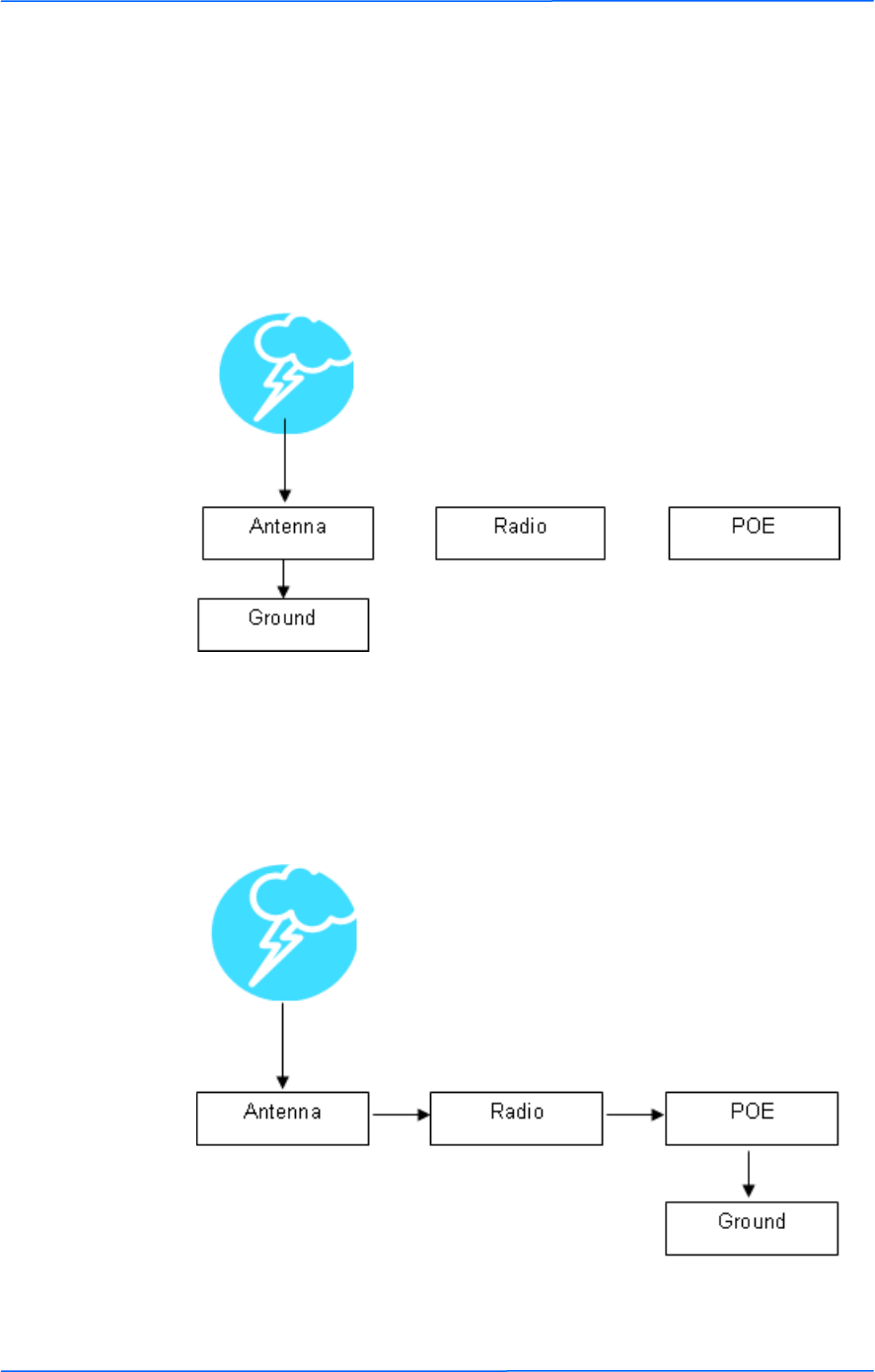
Where to ground the device?
This radio must be grounded at the pole and at the POE. This is because the radio
is between the exterior antenna and the POE ground. See the examples below.
Grounded Radio
A grounded radio causes the surge to pass directly to ground, bypassing the radio.
Ungrounded Radio
An ungrounded radio causes the surge to pass through the radio. In this case, the
radio most likely will be damaged.
333
This document is intended for Public Distribution
19473 Fraser Way,
Pitt Meadows, B.C. Canada V3Y 2V4
Appendix A
A-3
TR-FDD Series
Tranzeo Wireless Technologies
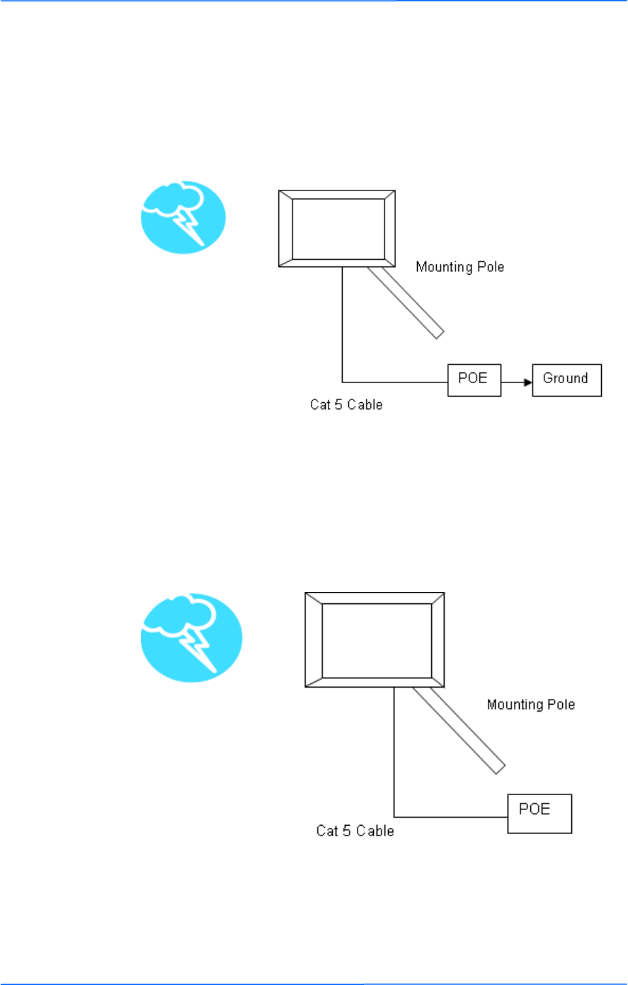
Grounded POE
In this case, the surge will be picked up by the Cat 5 cable and since the POE is
grounded, the route for the surge is through the POE to ground.
Ungrounded POE
In this case, the surge will be picked up by the Cat 5 cable and since the POE is
not grounded, the route for the surge is through the radio to the antenna, and out
through the building.

111
This document is intended for Public Distribution
19473 Fraser Way,
Pitt Meadows, B.C. Canada V3Y 2V4
Appendix B
B-1
TR-FDD Series
Tranzeo Wireless Technologies
Appendix B: Channel Allocations
The following tables list the channel numbers and center frequencies used for
802.11a. Note that while all of these frequencies are in the unlicensed ISM and U-
NII bands, not all channels are available in all countries. Many regions impose
restrictions on output power as well as indoor and outdoor use on some channels.
These regulations are rapidly changing, so always check your local regulations
before transmitting.
These tables show the center frequency for each channel. Channels are 20 MHz
wide in 802.11a.
802.11a
Channel # Center Frequency
(GHz)
149 5.745
153 5.765
157 5.785
161 5.805
165 5.825
111
This document is intended for Public Distribution
19473 Fraser Way,
Pitt Meadows, B.C. Canada V3Y 2V4
Appendix C
C-1
TR-FDD Series
Tranzeo Wireless Technologies
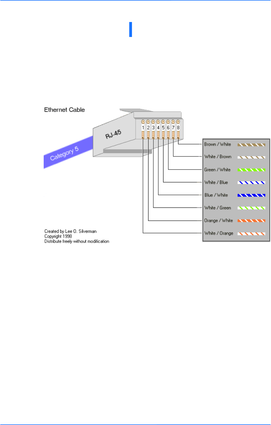
TIA/EIA-568-B is a set of standards for cabling telecommunications products and
services. Follow these standards, as described in the diagram below, to wire the
Cat 5 cable during installation of the Tranzeo radio (see Step 3 in Chapter 2:
Hardware Installation - Installing the Ethernet Cable).
Appendix C: Wiring Standard
111
This document is intended for Public Distribution
19473 Fraser Way,
Pitt Meadows, B.C. Canada V3Y 2V4
Appendix D
D-1
TR-FDD Series
Tranzeo Wireless Technologies
Step 1: Finding the Location
The following are some of the steps you should go through when
planning a Point to Point (PxP) link.
Determine the 2 endpoint locations.
Calculate the distance between the
locations.
Find the heights of the locations
Step 2: Check the Line of
Make sure that the line of sight is clear of obstruction.
Check your Fresnel clearance with calculations to verify that you have enough room in
the center of the path.
Take photos of the line of sight from both sides of the proposed link.
See example 1 below.
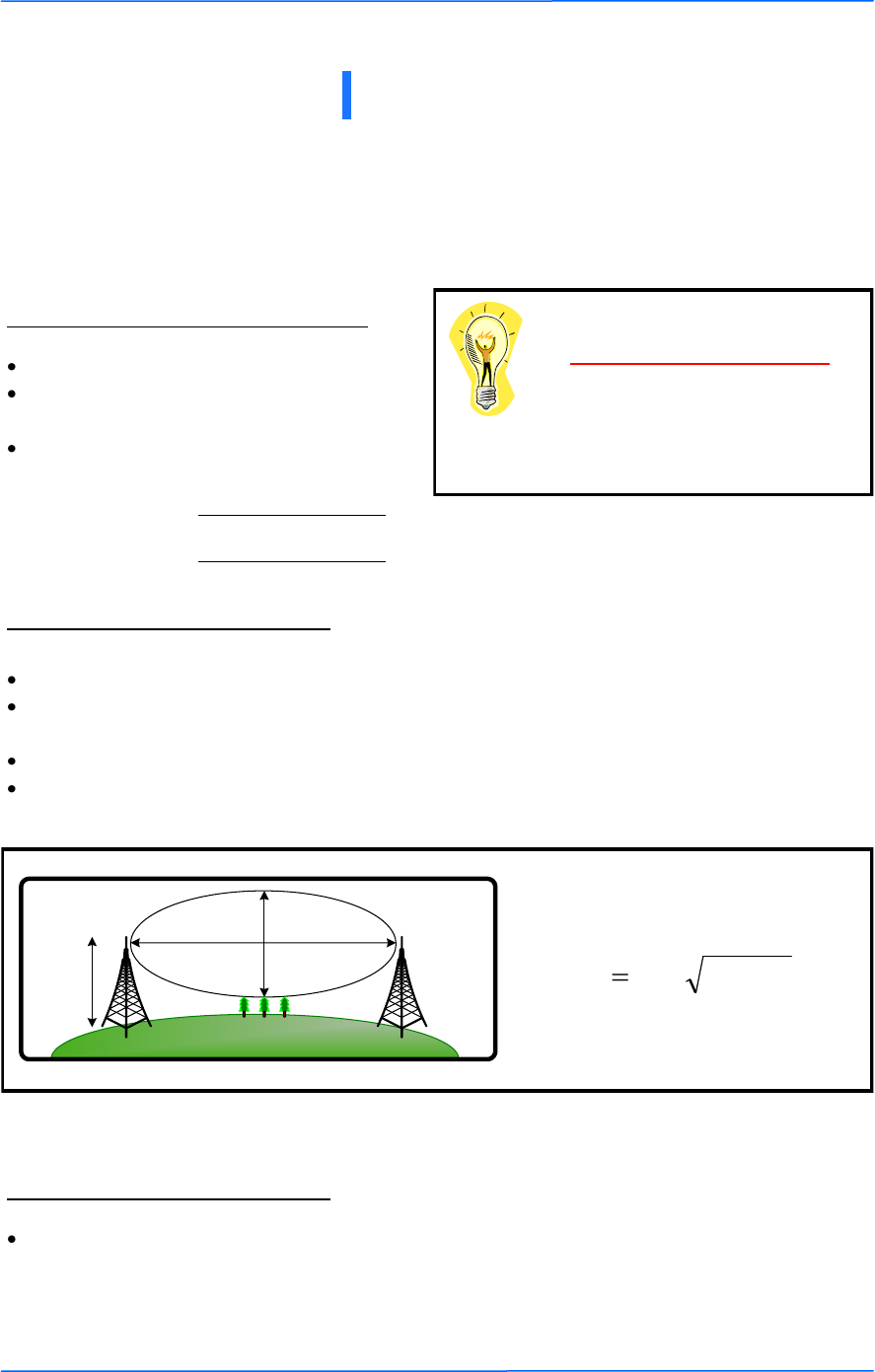
Example 1: Fresnel Zone Calculation
Step 3: Choose Hardware
Free space attenuation = 36.6 + 20log F + 20log D
where F = frequency in MHz and D = distance in
miles
Free Space Loss
Appendix D: PxP Install Checklist
Link Distance
Tower Heights
Fresnel zone
The cross section radius of the Fresnel zone
is the highest in the center of the RF LoS
which can be calculated as:
where r = radius in feet,
d = distance in miles,
and f = frequency in GHz.
)4/(3.43 fdr
Antenn
a
Height
r = radius
d =
distance
Select the hardware appropriate for the distance and type of link that you are installing

111
This document is intended for Public Distribution
19473 Fraser Way,
Pitt Meadows, B.C. Canada V3Y 2V4
Appendix E
E-1
TR-FDD Series
Tranzeo Wireless Technologies
Appendix E: Glossary of Terms
AP: Access Point
ARP: Address Resolution Protocol
CPE: Client Premise Equipment
CTS: Clear To Send
DFS: Dynamic Frequency Selection
DHCP: Dynamic Host Configuration Protocol
DNS: Domain Name Server
DTIM: Delivery Traffic Indication Message
EIRP: Effective Isotropic Radiated Power
FTP: File Transport Protocol
HTML: HyperText Markup Language
HTTP: HyperText Transport Protocol
IP: Internet Protocol
ISP: Internet Service Provider
LAN: Local Area Network
MTU: Maximum Transmission Unit
NAT: Network Address Translation
NIC: Network Interface Card
NOC: Network Operation Center
POP: Post Office Protocol or Point Of Presence
PxP: Point to Point
P2P: Peer to Peer
PPPoE: Point-to-Point Protocol over Ethernet
QOS: Quality Of Service
RADIUS: Remote Authentication Dial-in User Service
RF: Radio Frequency
RTS: Request To Send
SMTP: Simple Mail Transport Protocol
SNMP: Simple Network Management Protocol
TCP: Transmission Control Protocol
TPC: Transmit Power Control
UDP: User Datagram Protocol
VPN: Virtual Private Network
WAN: Wide Area Network
WEP: Wired Equivalent Privacy
WDS: Wireless Distribution System
WINS: Windows Internet Naming Service
WISP: Wireless Internet Service Provider
WPA: Wi-Fi Protected Access
111
This document is intended for Public Distribution
19473 Fraser Way,
Pitt Meadows, B.C. Canada V3Y 2V4
Appendix F
F-1
TR-FDD Series
Tranzeo Wireless Technologies
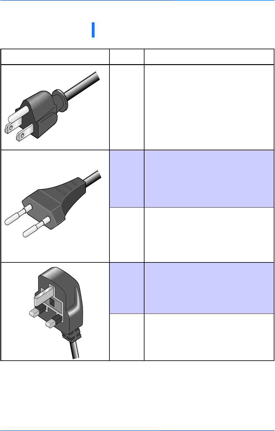
Appendix F: Tranzeo Electrical Plugs
Electrical Plug Type Letter Description
*
F FCC / North American
adapter
C ETSI / Euro adapter
FCC / Euro adapter A
U ETSI / UK adapter
FCC / UK adapter M
* 24 volt version shown.

111
This document is intended for Public Distribution
19473 Fraser Way,
Pitt Meadows, B.C. Canada V3Y 2V4
Appendix G
G-1
TR-FDD Series
Tranzeo Wireless Technologies
Warranty Terms For Canada / US
1. The following Tranzeo Wireless manufactured products are warranted against defects in
material and workmanship for a period of one year from date of purchase, under normal use.
All products manufactured prior to May 1st, 2006
All TR-CPE200-N
All TR-CPE200-15
All TR-CPE200-19
All Antennas
All Cables
2. All Tranzeo Wireless Power Over Ethernet and power supplies adaptors are covered by a 90
day warranty.
3. All other Tranzeo Wireless CPE, AP and Backhaul Radio products manufactured after May 1st,
2006 are warranted against defects in material and workmanship for a period of two years
from date of manufacture, under normal use.
4. All other Tranzeo Wireless CPE, AP and Backhaul Radio products manufactured after Dec 1st,
2006 are warranted against defects in material and workmanship for a period of three years
from date of manufacture, under normal use.
5. Tranzeo Wireless manufactured products are covered by a Parts and Labor Depot Warranty.
Depot warranty means the customer is responsible for delivering the defective product to the
designated service depot for repair or replacement.
6. Tranzeo Wireless will repair or replace a product that was found to be defective by Tranzeo
during the warranty period at its discretion.
7. All non-Tranzeo manufactured products carry the Original Equipment Manufacturer's warranty,
which is passed on by Tranzeo Wireless. Warranty Claims against non-Tranzeo manufactured
products must be filed with the appropriate manufacturer.
8. This warranty does not cover dealer labor cost for removing and reinstalling the machine for
repair nor for any expendable parts that are readily replaced in normal use.
9. The sole responsibility of Tranzeo Wireless Systems under this warranty shall be limited to
repair of this product, or replacement thereof, at the sole discretion of Tranzeo Wireless
Systems.
10. All RMA items shipped to Tranzeo Wireless must be freight prepaid. Tranzeo Wireless will pay
the return freight via a service of Tranzeo Wireless Technologies’ choice. Customer is
responsible for payment of any shipping upgrades.
Warranty Terms For The European Union
1. All Tranzeo Wireless Power Over Ethernet and power adaptors are covered by a 90 day
warranty.
2. All other Tranzeo Wireless manufactured CPE; AP and Backhaul Radio products are
warranted against defects in material and workmanship for a period of two years from date of
purchase, under normal use.
3. All other Tranzeo Wireless CPE, AP and Backhaul Radio products manufactured after Dec 1st,
2006 are warranted against defects in material and workmanship for a period of three years
from date of manufacture, under normal use.
4. Products must be used in accordance with relevant local regulations. Only products designed
for and marketed to the European Market by Tranzeo will be honored for warranty service.
5. Tranzeo Wireless manufactured products are covered by a Parts and Labor Warranty. The
customer is responsible for delivering the defective product to the designated service depot for
repair or replacement.
6. Tranzeo Wireless will repair or replace a product that was found to be defective by Tranzeo
during the warranty period at its discretion.
Appendix G: Warranty Terms

222
This document is intended for Public Distribution
19473 Fraser Way,
Pitt Meadows, B.C. Canada V3Y 2V4
Appendix G
G-2
TR-FDD Series
Tranzeo Wireless Technologies
7. All non-Tranzeo manufactured products carry the OEM's warranty, which is passed on by
Tranzeo Wireless. Warranty Claims against non-Tranzeo manufactured products must be
filed with the appropriate manufacturer.
8. This warranty does not cover dealer labor cost for removing and reinstalling the machine for
repair nor for any expendable parts that are readily replaced in normal use.
9. VAT, Customs and other local taxes are the responsibility of customer.
10. The sole responsibility of Tranzeo Wireless Systems under this warranty shall be limited to
repair of this product, or replacement thereof, at the sole discretion of Tranzeo Wireless
Systems.
11. All RMA items shipped to Tranzeo Wireless must be freight prepaid. Tranzeo Wireless will
arrange the return freight. Customer is responsible for payment of any shipping costs.
Shipping costs must be pre-paid before the item is shipped.
Warranty Terms For The Rest of the
World
1. The following Tranzeo Wireless manufactured products are warranted against defects in
material and workmanship for a period of one year from date of purchase, under normal use.
TR-CPE200-N
TR-CPE200-15
TR-CPE200-19
2. All Tranzeo Wireless Power over Ethernet adaptors are covered by a 90 day warranty.
3. All other Tranzeo Wireless manufactured CPE; AP and Backhaul Radio products are
warranted against defects in material and workmanship for a period of two years from date of
purchase, under normal use.
4. Tranzeo Wireless manufactured products are covered by a Parts and Labor Warranty. The
customer is responsible for delivering the defective product to the designated service depot for
repair or replacement.
5. Tranzeo Wireless will repair or replace a product that was found to be defective by Tranzeo
during the warranty period at its discretion.
6. All non-Tranzeo manufactured products carry the OEM's warranty, which is passed on by
Tranzeo Wireless. Warranty Claims against non-Tranzeo manufactured products must be
filed with the appropriate manufacturer.
7. This warranty does not cover dealer labor cost for removing and reinstalling the machine for
repair nor for any expendable parts that are readily replaced in normal use.
8. VAT, Customs and other local taxes are the responsibility of customer.
9. The sole responsibility of Tranzeo Wireless Systems under this warranty shall be limited to
repair of this product, or replacement thereof, at the sole discretion of Tranzeo Wireless
Systems.
10. All RMA items shipped to Tranzeo Wireless must be freight prepaid. Tranzeo Wireless will
arrange the return freight. Customer is responsible for payment of any shipping costs.
Shipping costs must be pre-paid before the item is shipped.
Limitation of Warranty
This warranty does not apply if the Product:
has been opened and/or altered, except by Tranzeo Wireless technical personnel,
has been painted in way shape or form,
has been damaged due to errors or defects in cabling
has not been maintained in accordance with instructions supplied by Tranzeo
Wireless,
has been subjected to abnormal physical or electrical stress, including lightening

333
This document is intended for Public Distribution
19473 Fraser Way,
Pitt Meadows, B.C. Canada V3Y 2V4
Appendix G
G-3
TR-FDD Series
Tranzeo Wireless Technologies
strike, misuse, negligence, or accident;
removal of serial number label, or
equipment sold under resale agreements, i.e. Amplifiers, Antennas.
Who to Contact for an RMA?
There are 3 ways to discuss any technical difficulties and request an RMA #:
1. Fill out our online RMA Request Form at support@tranzeo.com
2. Call our Technical Support Center at 604-460-6002
3. Or email our RMA Department at rma@tranzeo.com
What information will be required?
Dealer Username and Password
Customer name/ID # and contact information
Warranty Status (Data of purchase)
Problem Description
Part Number or Serial Number
Troubleshooting actions taken so far
Warranty Repair
a) RMA number is valid for 90 days only.
b) If the product is not received within 90 days, the RMA will be cancelled.
c) Tranzeo Wireless will carefully test and evaluate all returned products and will repair or
replace defective products that are under warranty at no charge.
d) If the malfunction is due to a manufacturing defect, it will be repaired, tested, aligned and
calibrated as necessary, with strict adherence to factory specified procedures and parts, to
working order.
e) If the malfunction is due to an issue not covered by warranty, a $35.00 evaluation fee will be
charged, plus the actual costs of the repair. Tranzeo's current shop rate is $70.00 per hour,
plus parts.
f) When your unit is returned to you, you must restore configuration and or applications before
full use can resume.
g) If the product cannot be repaired, a refurbished replacement product will be provided.
h) However, if Tranzeo Wireless cannot duplicate the problem or condition causing the return,
the unit will be returned to the customer at the customers cost as: "No Problem Found" and a
$35.00 evaluation fee may be charged.
i) Repaired or replaced product will be subject to the original warranty period but not less than
30 days.
j) All items must be shipped pre-paid. Tranzeo Wireless will not accept any collect packages.
Tranzeo will pay the shipping to return your products. We recommend insuring the package
using the values from our commercial invoice.
k) Be sure to package the items well. Original packaging should be used for shipping. Tranzeo is
not responsible for further damage caused to the unit due to inadequate packaging.
l) We recommend that you use a shipping service with tracking (i.e. UPS/FedEx ground) to ship
your RMA. Tranzeo will not accept any packages that arrive with charges owing.
m) Be sure to include the password for each device. Any device that arrives without a password
may be subject to a $60 rebuilding charge per unit.

444
This document is intended for Public Distribution
19473 Fraser Way,
Pitt Meadows, B.C. Canada V3Y 2V4
Appendix G
G-4
TR-FDD Series
Tranzeo Wireless Technologies
Out of Warranty Replacements
Product that is out warranty will be repaired on a fee for service basis at Tranzeo's shop rate of
$70.00 per hour plus parts. A $75.00 deposit is charged for all non-warranty repairs when the
RMA is issued.
Any goods left for more than 90 days without instructions will be considered abandoned and be
disposed of.
What to ship?
Products that are returned for RMA work should be shipped in the original package and include
the items that that are to be repaired. All returned product must reference the RMA # on the
outside of the box. A returned product without clearly marked RMA# will be refused and returned
to sender.
How to ship?
We recommend that you use a shipping service with tracking (i.e. UPS/FedEx ground) to ship
your RMA.
Products returned for warranty repair or out-of-warranty replacement, must be marked with a
valid RMA number and shipped FOB Destination, Prepaid.
Approximate turnaround time is 7 business days for warranty repairs and replacements.
Shipping Time is generally 7 business days to any location in the United States.
Tranzeo Wireless will refuse any item that does not have an RMA# clearly marked on the
outside of the box.
Tranzeo Wireless is NOT responsible for any damage to the products during transit by the
shipping company.
All claims for shipment errors must be made within 3 days after receipt of shipment.
Warranty Disclaimer
Except in only the limited express warranty set forth above, there are no expressed or implied
warranties of merchantability and fitness for a particular purpose. In no event will Tranzeo
Wireless Systems be liable for any direct, special, or consequential damages arising out of, or in
connection with, the delivery, use, inability to use, or performance of this product.

555
This document is intended for Public Distribution
19473 Fraser Way,
Pitt Meadows, B.C. Canada V3Y 2V4
Appendix G
G-5
TR-FDD Series
Tranzeo Wireless Technologies
Goods Damaged in Transit
Tranzeo Wireless Technologies ships all item FOB Factory. This means that title for the
item transfers to the buyer once the courier picks up the package. If there is damage, a
claim must be filed with the courier by the owner of the goods, which is the buyer.
Shipping damage is not covered by the warranty. Damage claims are between the recipient
of the goods and the courier.
Shipping Firms do have legal obligations and limitations as to when and how much to
compensate for damage, but only if the claim is filed on time and in the correct manner.
You must file the claim as soon as possible.
Making a Damage Claim
If you receive a shipment that appears to have been damaged by
the shipper during shipping, take the steps on the on the box
(shown below), then contact us so we have a record of the
incident. We will assist in any way we can in filing and
advocating for your claim.
If you choose to accept the shipment and sign for it, have the shipper stay with you while
you open and inspect the contents of the container for any additional damage that was
not visible before opening. Make sure the shipper notes all damage on the shipping bill
before you sign. By signing the waybill, you release the Shipping Company from all
obligations unless the damage is clearly noted.
If it is possible to take any photos of the damage and forward to the shipper and us,
Before signing the shipping bill (for receipt of the shipment), have the shipper note on
the shipping bill the exact details of the damage.

111
This document is intended for Public Distribution
19473 Fraser Way,
Pitt Meadows, B.C. Canada V3Y 2V4
Appendix H
H-1
TR-FDD Series
Tranzeo Wireless Technologies
Appendix H: How Can We Improve?
Please take a moment to help us improve your experience with Tranzeo Wireless. Please fax the
completed questionnaire to 604-460-6005. Each month we will draw for a free gift.
Product Quality
Service and Environment
Additional Comments
_______________________________________________________________________________
_______________________________________________________________________________
About You (optional)
Thank you for your participation!
Was this your first order from Tranzeo
Wireless?
Yes
No
Was your order complete?
Yes
No, I was missing:
_______________________
How would you rate our website?
Very Informative
Generally good
Quality varies
Poor quality
How would you rate our packaging?
Consistent high quality
Generally good
Quality varies shipment to shiment
Poor quality
How would you rate our order process?
Consistent high quality
Generally good
Quality varies daily
Poor quality
How would you rate our Technical Support?
Consistent high quality
Generally good
Quality varies each time
Poor quality
Did you Sales Rep answer all your questions
and explain your best options?
Yes
No
How long did you wait for your product
after ordering?
1 to 3 days
3 to 5 days
More than 5 days
How would you rate the Tranzeo Wireless
staff you have dealt with to date?
Friendly and helpful
Average
Varies on each call
Poor service
Was the entire experience positive?
Yes
No
If No why?:___________________
Name E-mail
Address Phone
City, State, ZIP Code
May we add you to our mailing list, which offers news and exciting promotions? □ Yes □ No

111
This document is intended for Public Distribution
19473 Fraser Way,
Pitt Meadows, B.C. Canada V3Y 2V4
Appendix I
I-1
TR-FDD Series
Tranzeo Wireless Technologies
Appendix I: Notes