Tranzeo Wireless Technologies TR-3115 802.11b Wireless Network Device User Manual quick start manual
Tranzeo Wireless Technologies, Inc 802.11b Wireless Network Device quick start manual
Contents
- 1. quick start manual
- 2. users manual
quick start manual
Quick Start
ISP Access Point
ISP’s use Access Points to provide you with Internet
service. This allows them to send the “Internet” to you
wirelessly. The AP talks to Station Adapters and visas versa.
ISP’s TR–2015/TR–2018/TR–1000/TR–2000 Unit
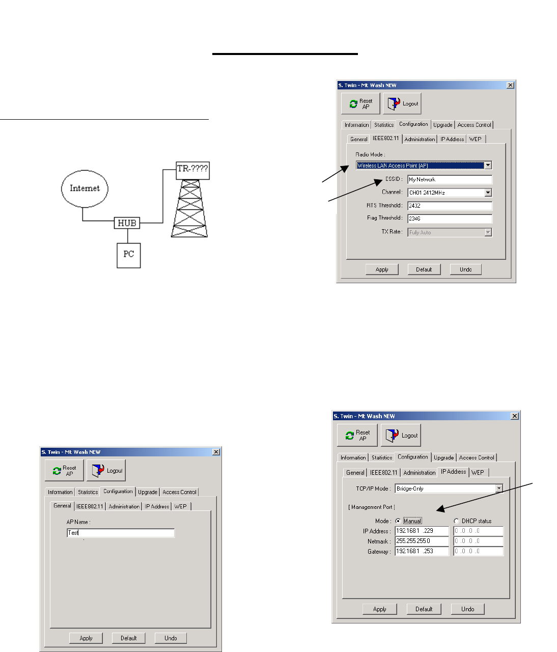
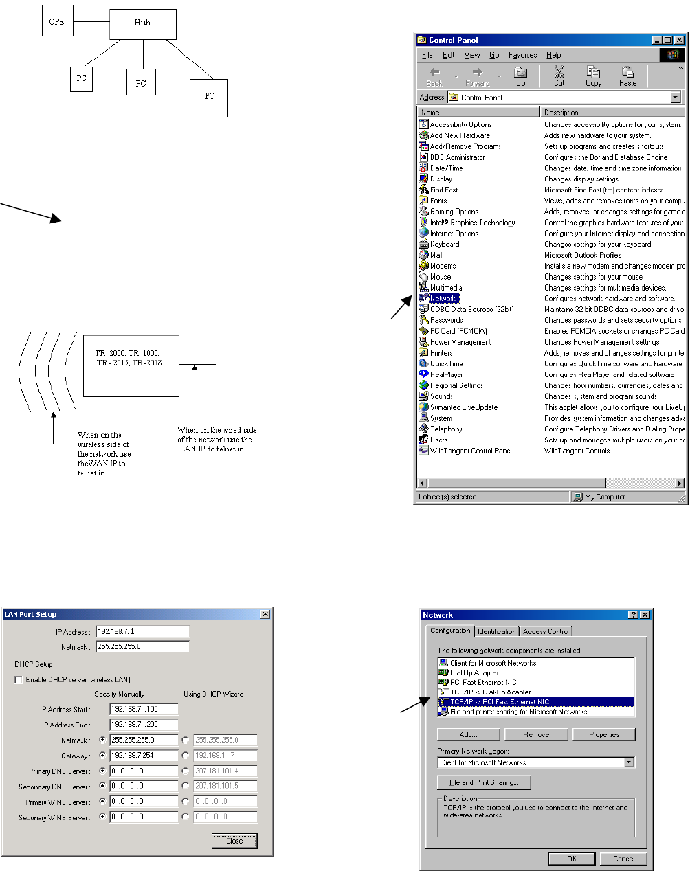
1. Plug your Cable, DSL, or other type of Internet service
into the uplink port of your hub. (Fig 1)
5
4
Figure 1
Figure 3
From the Hub plug one line into the Ethernet adapter
on your computer. Plug a crosspatch cable into the
Port marked PC on the DC injector. Plug the TR–
2015/TR–2018/TR–1000/TR–2000 into the port
marked CPE on the DC injector. Plug DC power
supply into the DC Injector.
5. Set the ESSID by typing in an ID. (Fig 3)
Note: You must have an ESSID entered into the box.
6. Hit Apply. Hit OK for reset.
7. Click the IP Address tab and set the TCP/IP Mode to
Bridge-Only. (Fig 4)
a. Click the DHCP Status Radio Button to
receive an address via a DHCP server or
select manual to manually assign an IP
address.
2. Install the Access Point Utility from the CD. Execute
the utility and double click on the icon of the TR–
2015/TR–2018/TR–1000/TR–2000. Enter the
Password. The default password is “default”.
3. Click the Configuration tab and then the General tab.
Name the Access Point so you can easily identify the
unit. (Fig. 2)
a.
Figure 4
8. Hit Apply. Hit OK to reset.
9. To check signal strength start a telnet session by
going to the Start Menu and select Run. Type in
“telnet” and the IP of the unit. Enter password. Type
“stat” and hit enter. Signal Strength is displayed
across the top.
Figure 2
4. Click the IEEE802.11 tab and use the drop down
menu to set the Radio Mode to Wireless LAN Access
Point (AP). (Fig 3)
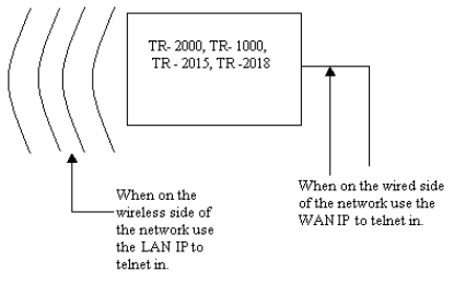
To manage the TR–2015/TR–2018/TR–1000/TR–2000
from inside your network use the gateway’s address to telnet or
when using your browser. To remotely manage the TR–
2015/TR–2018/TR–1000/TR–2000 (from an outside location)
use the IP address of the TR–2015/TR–2018/TR–1000/TR–
2000. (Fig 5)
Figure 5
2
Station Adapter with IP Routing
4
5
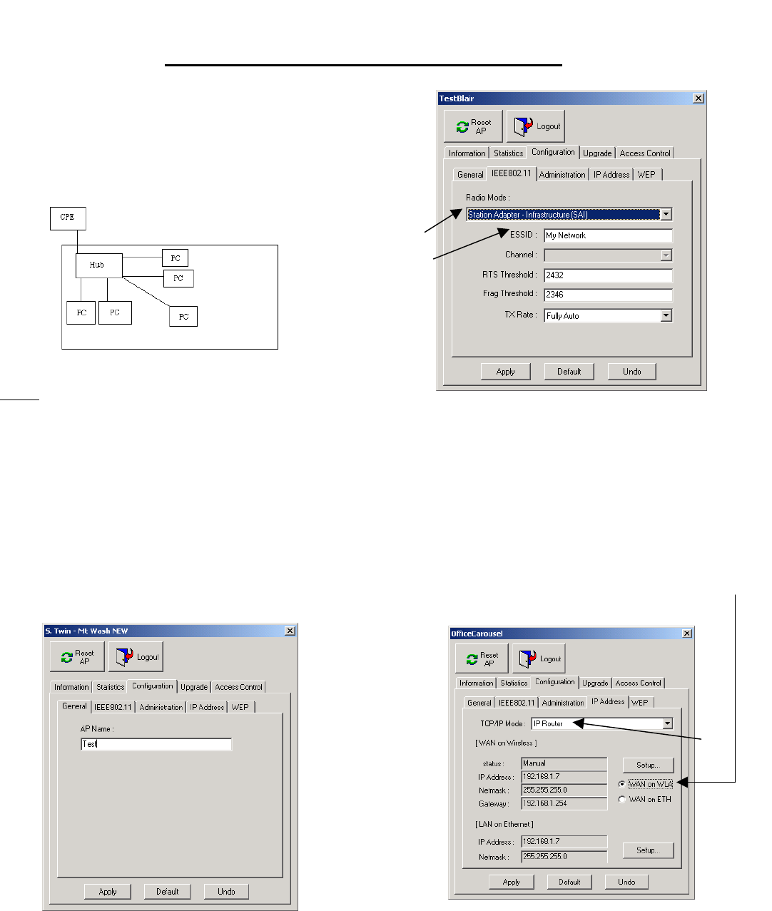
IP Routing allows for multiple computers to share a
connection. This means that you can have multiple
computers using 1 CPE to gain access to your network.
You set the CPE to assign IP addresses within a specified
range (e.g. 192.168.1.10 to 192.168.1.200). By setting the
CPE to Station Adapter Mode the unit is able to send and
receive data to and from an Access Point. (Fig 6)
Quick Start
Figure 6
Setup
Figure 8
1. Plug the Cat 5 coming out of the TR-2015/2018/2000
into the port marked CPE on the DC injector. Plug
another cable into the PC port on the DC injector and
into an Ethernet adaptor for a single PC or into an
uplink port on a hub for multiple computers. Note if no
uplink port is available, you must use a crosspatch
cable.
5. Enter the ESSID of the AP that you wish to connect
to. It MUST be the same as the AP that you wish to
connect to.
6. Hit Apply. Click OK to reset.
7. For privacy on the network and/ or sharing the
connection for multiple computers you need to do the
following: (Fig 9)
2. Install the Access Point Utility. Execute the utility and
double click on the icon of the CPE. Enter the
Password. The default password is “default”.
a. Click the IP Address tab and change the
TCP/IP Mode from Bridge-Only to IP
Router.
3. Click the Configuration tab and then the General tab.
Name the Access Point so you can easily identify the
unit. (Fig 7)
b. Select WAN on the WLA (Wide Area
Network on Wireless LAN) radio button.
Figure 7
4. Click the IEEE802.11 tab and use the drop down
menu to set the Radio Mode to Station Adapter –
Infrastructure (SAI). (Fig 8)
a.
b.
Figure 9
From here there are two possible routes to choose, DHCP
or Manual.
3
IF You Choose Manual then:
i. Ensure that the subnets are the
same in the IP Address and the
Range of IP’s that you wish to have
given out (the third number in the
IP Address).
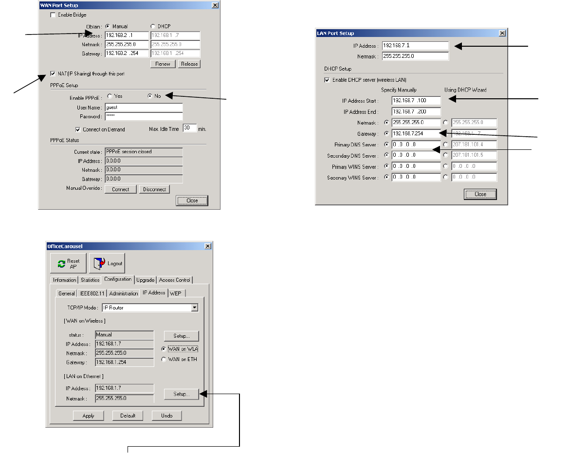
1. Click on the Setup Button above the WAN on WLA
and WAN on ETH (Wide Area Network on Ethernet)
radio buttons.
a. Set the Obtain radio buttons to “Manual” and
set the IP Address (for management purposes
e.g. telnet, pining etc…), netmask, and
gateway.
If you wish the have a DHCP server on the LAN side to assign
DNS values etc… follow the steps below: (Follow the steps
outlined after this section if you wish to manually configure
those units)
b. Check the NAT (IP Sharing) through this port
box. (Fig 10 a) a. Check the box
c. Turn off PPPoE by clicking the no. b. Set the range of IP’s that you want to have given
out to the multiple computers that can be
connected to this CPE.
a.
4
b. c.
a.
b.
d.
c.
Figure 12 a
Figure 10 a c. Set the Gateway to XXX.XXX.XXX.254 or
XXX.XXX.XXX.1
2. Close the window by hitting the close button.
i. Ensure that the subnets are the
same.
d. Enter the DNS settings into the boxes.
If you have DHCP Client enabled on your PC the unit will
send all relevant information to your PC automatically.
4. Hit Apply.
. For multiple computers do the following:
a. Follow steps 1-4 and then follow below.
b. Plug the Cable coming out of the CPE into the
port marked CPE on your DC Injector.
c. Plug a cable into the port marked PC on the DC
Injector into the uplink port on the hub or if
uplink port is not available use a crosspatch
cable.
Figure 11
3.
d. Plug another Ethernet cable into an available port
on the hub and put the other end into the
3. Click the LAN on Ethernet setup button.
a. Enter the IP Address into the box marked IP
Address.
For Windows 98 Users:
Ethernet card in your PC. (Fig 12 a)
1. Click Start button, then Settings, then Control Panel.
2. Click the network icon in the list as in Figure 15.
Figure 13 a
e. Check the connection by opening a web page (that
isn’t cached) in your browser.
f. Repeat step d. for more computers.
To check signal strength start a telnet session by going to
the Start Menu and select Run. Type in “telnet” and the IP of
the unit. Enter password. Type “stat” and hit enter. Signal
Strength is displayed across the top.
To manage the CPE from inside your network use the
gateway’s address to telnet or when using your browser. To
remotely manage the CPE (from an outside location) use the IP
address of the CPE. (Fig 13 a) 2.
3.
Figure 14 a
Figure 15
If you do not wish to have a DHCP server on the LAN side
assigning DHCP follow the steps below for EACH computer on
the CPE:
3. Select the TCP/IP icon in the list and click properties.
(Note: there is usually only one TCP/IP icon in the
list but if there is two or more select your Ethernet
card.)
1. Un check the box labeled “Enable DHCP Server
(wireless LAN)”
5
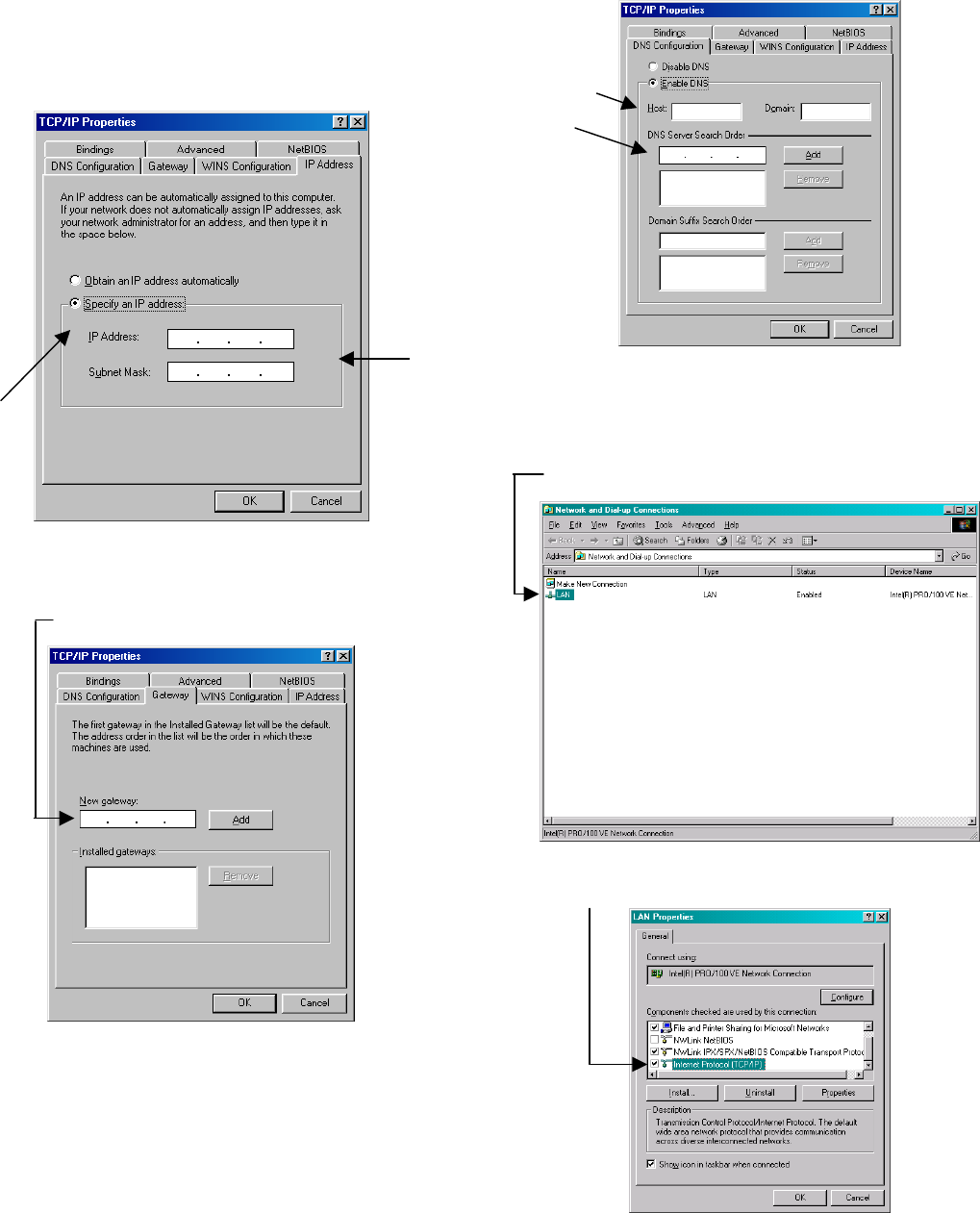
Figure 16
For all information to enter into the boxes, contact your
network administrator.
4. Click the Specify an IP Address radio button.
a. Enter the IP address and the Subnet mask.
Figure 17
5. Click the Gateway tab
a. Enter the gateway.
b. Click the Add button.
Figure 18
6. Click the DNS Configuration tab.
a. Click the Enable DNS.
i. Enter the host.
ii. Enter the DNS into the box and click
Add.
iii. Enter the Domain ONLY if there is
one.
Figure 19
For Windows 2000 users:
1.
2.
Click the Start Button, then Settings, and then select
Network and Dial-up Connections.
Right click on the Network connection that will be in
the window and click properties.
Figure 20
3. Select the TCP/IP icon in the list and click properties.
Figure 21
6
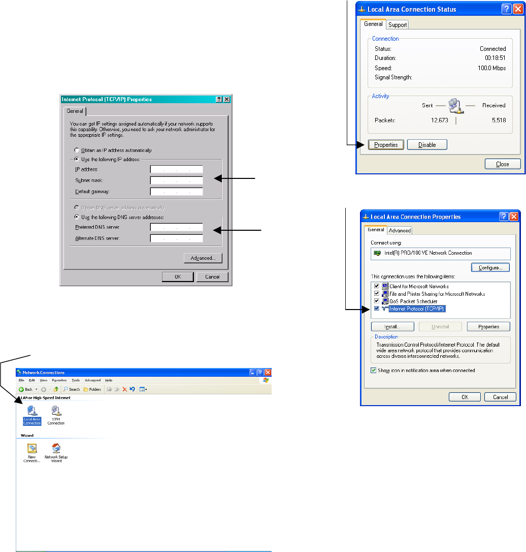
4. Click the “Use the Following IP Address” radio
button.
4. Click the Properties button.
For all information to enter into the boxes, contact your
network administrator.
a. Enter the IP address, Subnet Mask, and
Default Gateway.
b. Enter the preferred and Alternate DNS
values.
c. Click OK.
Figure 22
For Windows XP users:
1.
2.
3.
Click the Start Button, then Control Panel.
Click the Network Connections Icon.
Double Click on your connection in the window as in
Figure 23.
Figure 23
Figure 24
5. Select TCP/IP from the list and click properties.
Figure 25
7
a. Enter the IP Address into the box marked IP
Address.
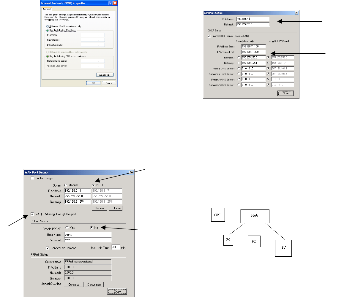
6. Click “Use the following IP Address” radio button.
For all information to enter into the boxes, contact your
network administrator. b. Set the range of IP’s that you want to have given
out to the multiple computers.
a. Enter the IP address, Subnet Mask, and
Default Gateway. i. Ensure that the subnets are the same in the
IP Address and the range of IP’s that you
wish to have assigned (the third number in
the Address).
b. Enter the preferred and Alternate DNS values
and click OK.
a.
b.
Figure 26
IF You Choose DHCP then: Figure 29 b
If you have a DHCP Server upstream (closer to the internet),
DHCP client on the WAN side, DHCP server on the LAN side
and the DHCP client turned on on your computer all relevant
information (IP address, Gateway etc…) will be passed on.
1. Set the radio buttons to Obtain “DHCP”.
a. Click the “release” button and then click the
“renew” button. Reset the unit. Go back to
the screen and repeat if the numbers do not
show up in the box. 4. Hit Apply.
For multiple computers do the following:
b. Check the NAT (IP Sharing) through this port
box. (Fig 10 b) a. Follow steps 1-4 and then follow below.
b. Plug the Cable coming out of the CPE into the
port marked CPE on your DC Injector.
c. Turn off PPPoE by clicking the no. a.
b. c.
c. Plug a cable into the port marked PC on the DC
Injector into the uplink port on the hub
d. Plug another Ethernet cable into an available port
on the hub and put the other end into the
Ethernet card in your PC. (Fig 30)
Figure 30
e. Check the connection by opening a web page
(that isn’t cached) in your browser.
f. Repeat step d. for more computers.
To check signal strength start a telnet session by going to
the Start Menu and select Run. Type in “telnet” and the IP of
the unit. Enter password. Type “stat” and hit enter. Signal
Strength is displayed across the top.
Figure 28 b
2. Close the window by hitting the close button.
3. Click the LAN on Ethernet setup button (bottom right
hand corner). To manage the CPE from inside your network use the
gateway’s address to telnet or when using your browser. To
8
remotely manage the CPE (from an outside location) use the IP
address of the CPE. (Fig 30)
Figure 27
9
Quick Start
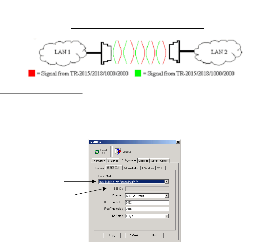
Quick Start For Bridging (PxP)
Figure 32
Customer Unit TR-2015/2018/1000/2000
1. Plug the Cat 5 cable coming out of the TR-2015/2018/2000 (the MDI port on the TR–1000) into the port marked CPE on the
DC injector. Plug another cable into the PC port on the DC injector and into an Ethernet adaptor for a single PC or an uplink
port on a hub for multiple computers. Plug the DC power supply into the DC Injector.
2. Install the Access Point Utility. Execute the utility and double click on the icon of the TR-2015/2018/1000/2000. Enter the
Password. The default password is “default”.
3. From the Configuration Tab select the General tab. Name the Access Point so you can easily identify the unit.
4. Click the IEEE802.11 tab and use the drop down menu to set the Radio Mode Inter-Building with Repeating (PxP).
Figure 33
5. Set the channel for your TR-2015/2018/1000/2000.
Ensure both TR-2015/2018/1000/2000’s are set to the same channel.
6. Hit apply. Click OK for reset.
7. Repeat for the other TR-2015/2018/1000/2000.
8. To check signal strength start a telnet session by going to the Start Menu and select Run. Type in “telnet” and the IP of the
unit. Enter password. The default password is “default”. Type “stat” and hit enter. Signal Strength is displayed across the top.
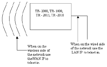
To manage the TR-2015/2018/1000/2000 from inside your network use the gateway’s address to telnet or when using your
browser. To remotely manage the TR-2015/2018/1000/2000 (from an outside location) use the IP address of the TR-
2015/2018/1000/2000.
4
5
10