Tranzeo Wireless Technologies TR-6019 WIRELESS NETWORKING DEVICE User Manual TR 6000 Quickstart Guide
Tranzeo Wireless Technologies, Inc WIRELESS NETWORKING DEVICE TR 6000 Quickstart Guide
Contents
- 1. USERS MANUAL 1
- 2. USERS MANUAL 2
USERS MANUAL 1


20155 Stewart Crescent,
Maple Ridge, B.C. Canada V2X 0T6
Phone (604) 460-6002 Fax (604) 460-6005
www.tranzeo.com
Page 2 of 24 3/10/2005
!"#$%!&'#() *"+##()#")#,*(,-.%(,)./.'&012!) ) #0!'!)"-.3*0*"",!4!)*0,#5!/#&%3"%*()).&*3)
.-) #%0#" #"#0!'!)"*3#,#"!4(#,).&3.5!,#3#*".(*+0#&3.)#/)!.(*4*!(") *3'-%0!()#3-#3#(/#2 #() #
#$%!&'#() !" .*)#, !( * #"!,#()!*0 #(5!3.('#() !" #$%!&'#() 4#(#3*)#" %"#" *(, /*( 3*,!*)# 3*,!.
-3#$%#(/1 #(#341 *(, !- (.) !(")*00#, *(, %"#, !( *//.3,*(/# 2!) ) # !(")3%/)!.( '*(%*0 '*1 /*%"# *3'-%0
!()#3-#3#(/#).3*,!./.''%(!/*)!.(
*)!.(.-) !"#$%!&'#()!(3#"!,#()!*0*3#*!"0!6#01)./*%"# *3'-%0!()#3-#3#(/#!(2 !/ /*"#) #%"#32!00+#
3#$%!3#,)./.33#/)) #!()#3-#3#(/#*) !".3 #3.2(#7&#("#
# %"#3 " .%0, (.) '.,!-1 .3 / *(4# ) !" #$%!&'#() 2!) .%) 23!))#( *&&3.5*0 -3.' 3*(8#. !3#0#""
.,!-!/*)!.(/.%0,5.!,*%) .3!)1).%"#) !"#$%!&'#()
.3) #"*-#)13#*".("&#.&0#" .%0,(.)2.36!(*"!)%*)!.(2 !/ 7&."%3#0!'!)"+##7/##,#,.&3#5#()
) #"!)%*)!.( *&&#(!(4&#.&0#2 .2.362!) ) #*()#((*" .%0,+#*2*3#.-) #-.00.2!(43%0#"
(")*00) #*()#((*!(*0./*)!.(2 #3#*,!")*(/#.-/'-3.') #*()#((*'*1+#'*!()*!(#,
!0#!(")*00!(4) #*()#((*,.(.))%3(.(&.2#3).) #%(!)
9 .(.)/.((#/)) #*()#((*2 !0#) #,#5!/#!"!(.*)!.(
: #*()#((*%"#,-.3) !")3*("'!))#3'%")(.)+#/.0./*)#,.3.*)!(4!(/.(;%(/)!.(2!) *(1.) #3
*()#((*.3)3*("'!))#3
!
" #!$
< <
=
• !"*()#((*>"43.%(,!(4"1")#''%")+#!(")*00#,*//.3,!(4).3)!/0#???.-) #
*)!.(*00#/)3!/.,#@A.BCC9-1.% *5#*(1$%#")!.(".3,.%+)"*+.%)1.%3*()#((*
43.%(,!(4"1")#'/.()*/)*0./*00!/#("#,#0#/)3!/!*(
• #5#3*))*/ ) #3.%(,!(4 !3#2 !0#) #,#5!/#!"&.2#3#,
• -) #43.%(,!").+#*))*/ #,).*(#7!")!(4#0#/)3!/*0/!3/%!))%3(.--) #/!3/%!)+#-.3#*))*/ !(4) #2!3#
• "#) #3*(8#.A.(012!) *&&3.5#,3*(8#.'.,#0"
• #5#3!(")*00*,!.$%!&'#()"%34#"%&&3#"".3".30!4 )(!(4&3.)#/)!.(,%3!(4*").3'
%& ''()"''
#6#1).*!4 )(!(4A3.)#/)!.(!"&3.5!,!(4* *3'0#""3.%)#-.30!4 )(!(4).3#*/ 43.%(, #"1")#'" .%0,
(.)+#,#"!4(#,).*))3*/)0!4 )(!(4(.3/*(!)3#�!4 )(!(4*)!.(*0)*)#*(,0./*0/.,#"*3#,#"!4(#,).
&3.)#/)0!-#0!'+*(,&3.)1*(,'%")*02*1"+#.+#1#,
& *+#,- !#.. .+.. . +! . /!!.+
*+!00#+0!!!

20155 Stewart Crescent,
Maple Ridge, B.C. Canada V2X 0T6
Phone (604) 460-6002 Fax (604) 460-6005
www.tranzeo.com
Page 3 of 24 3/10/2005
Introduction
This next-generation wireless LAN device – the TRANZEO TR-6000, brings Ethernet-like performance to the
wireless realm. Fully compliant with the IEEE802.11b standard, the TRANZEO TR-6000 also provides
powerful features such as the Internet-based configuration utility as well as WEP and WPA security. Maximize
network efficiency while minimizing your network investment and maintenance costs.
"# 1#+
Hardware Installation
Product Kit
Before installation, make sure that you have the following items:
• The TR-6000 x 1
• DC Power Adapter x 1
• Power over Ethernet Adapter x 1
• Ethernet Boot x 1
• Mounting Bracket x 1
• Ket Nuts (With Washer Attached) x 8
• U-Bolt w/ 2 Nuts x 1
• RJ-45 Patch Cable x 1
• Ethernet Boot Gasket x 1
• Ethernet Cable Lock x 2
• Optional: Ethernet Boot Tightening Bracket x 1
If any of the above items is not included or damaged, please contact your local dealer for support.

20155 Stewart Crescent,
Maple Ridge, B.C. Canada V2X 0T6
Phone (604) 460-6002 Fax (604) 460-6005
www.tranzeo.com
Page 4 of 24 3/10/2005
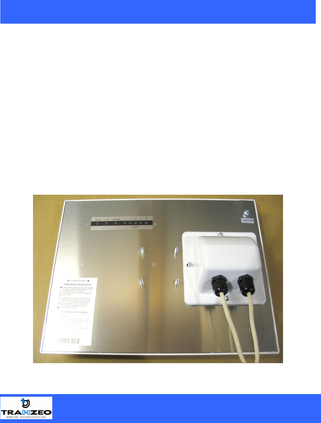
Mechanical Description
LED panel of the Wireless LAN Smart Access Point:
The following table provides an overview of each LED activity:
LED Definition Activity Description
Label Color Indicators
POWER Red On: Powered On
Off: No Power
LAN Green*
On: Ethernet Link
Flashing : Ethernet Traffic
Off: No Ethernet Link
Radio Amber
On: Radio Link
Flashing Radio Activity
Off: No Radio Link
Signal Red/Amber/Green
In CPE mode, light up in
sequence to indicate signal
strength
In AP mode the signal lights indicate the following:
Color Indicators
Red
On: WEP/128 Enabled
Flashing: WEP/64 Enabled
Off: WEP Off
Amber*
On: WPA/AES Enabled
Flashing : WPA/TKIP
Enabled
Off: WPA Off
Amber
Flashing: 2.4 GHz operation
Green On: ACL Enabled
Off: ACL Off
Green On: WDS Enabled
Off: WDS Off
Power Supply
ONLY use the power adapter supplied with the TR-6000. Otherwise, the product may be damaged.
20155 Stewart Crescent,
Maple Ridge, B.C. Canada V2X 0T6
Phone (604) 460-6002 Fax (604) 460-6005
www.tranzeo.com
Page 5 of 24 3/10/2005
Hardware Installation
Take the following steps to set up your TR-6000.
Site Selection: Before installation, determine the TR-6000 unit’s location. Proper placement of the unit is
critical to ensure optimum radio range and performance. You should perform a Site Survey to determine the
optimal location. Ensure the CPE is within line-of-sight of the Access Point. Obstructions may impede
performance of the unit.
Tools Required to Install
• One 3/8 wrench
• One 3/4 wrench
• One RJ-45 Crimper
• A suitable length of Cat 5 Cable to bring the signal from the unit to the Power over Ethernet Adaptor
• 2 RJ-45 Jacks
Before installing, you must determine if the unit will be in the horizontal or vertical orientation. The TR-6000
model can be mounted in either orientation. The Ethernet boot should always be placed so that the cable runs
toward the ground for maximum environmental protection.
20155 Stewart Crescent,
Maple Ridge, B.C. Canada V2X 0T6
Phone (604) 460-6002 Fax (604) 460-6005
www.tranzeo.com
Page 6 of 24 3/10/2005
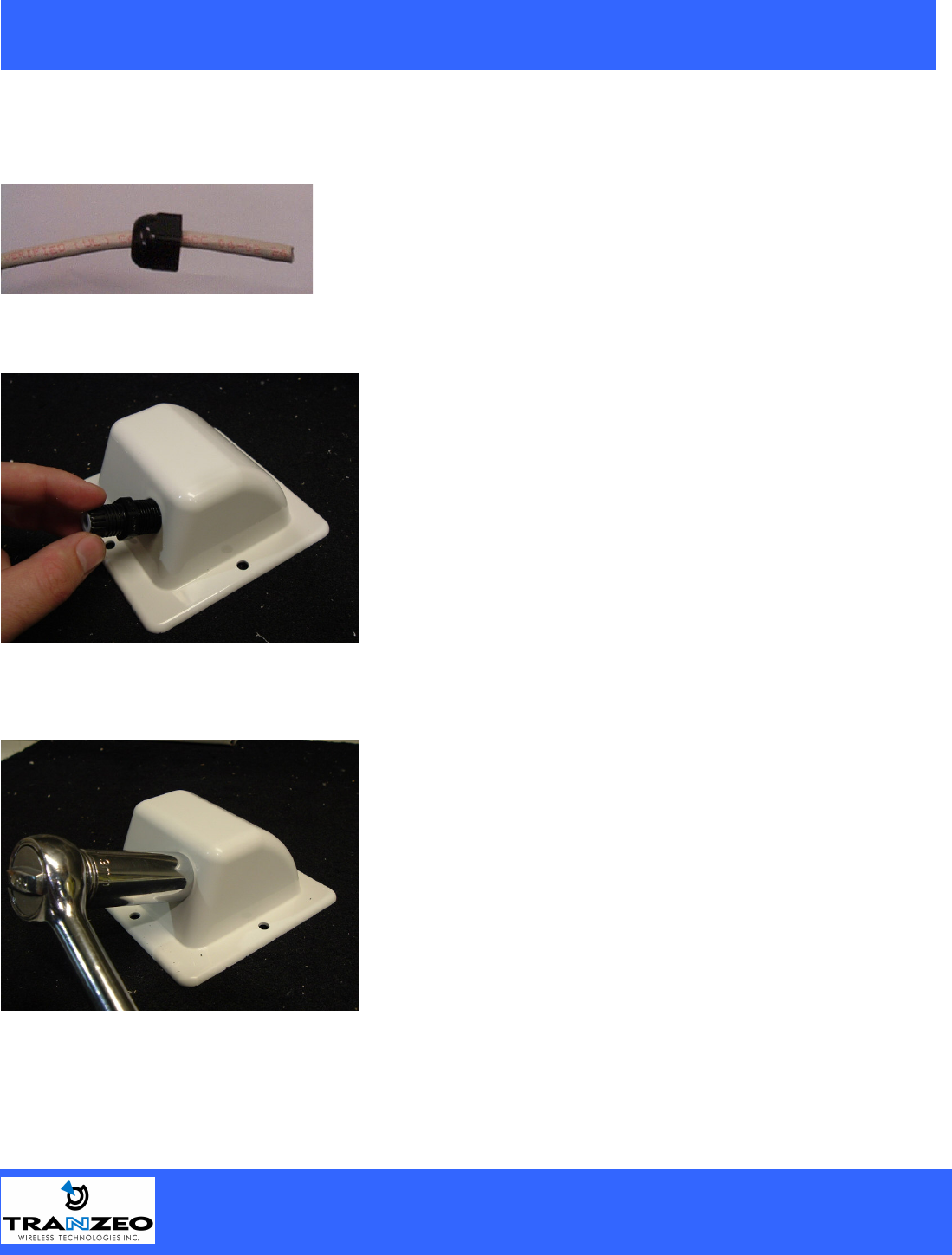
Connecting the Ethernet Cable
Step 1
Place the Ethernet Boot Cover over the end of your Cat 5 Cable. Attach
the sticky side of the gasket to the underside of the Ethernet Boot.
Step 2
Step 3
Tighten using a ¾” wrench or socket. Tighten until the
Cable Lock touches the Boot as shown in Step 3.
USE HAND TOOLS ONLY. DO NOT OVERTIGHTEN
as you may damage the environment seal.
Attach Ethernet Cable Lock on side of the Ethernet Boot.
This is easiest to do before you attach the RJ-45 Jack.
20155 Stewart Crescent,
Maple Ridge, B.C. Canada V2X 0T6
Phone (604) 460-6002 Fax (604) 460-6005
www.tranzeo.com
Page 7 of 24 3/10/2005
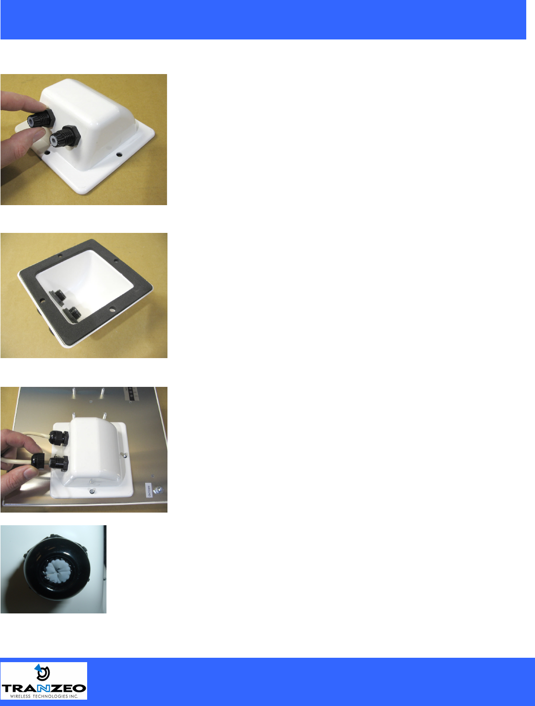
Step 4
Step 5
Step 6
Attach the Gasket to the Boot so that it sits between the
radio and the boot.
Insert the Cat 5 Cable and tighten the Boot Cover. Be sure
to pull enough cable through to reach the RJ-45 connector
with an RJ-45 jack attached. The Gasket must be attached
to the Boot so that it sits between the radio and the boot.
Hand tighten only. DO NOT OVERTIGHTEN as you may
damage the environment seal.
Repeat steps 2 & 3 to attach the second Ethernet Cable
lock.
If you are not going to be using the second port make sure
that it is tightened down to ensure a weather-tight seal.
20155 Stewart Crescent,
Maple Ridge, B.C. Canada V2X 0T6
Phone (604) 460-6002 Fax (604) 460-6005
www.tranzeo.com
Page 8 of 24 3/10/2005
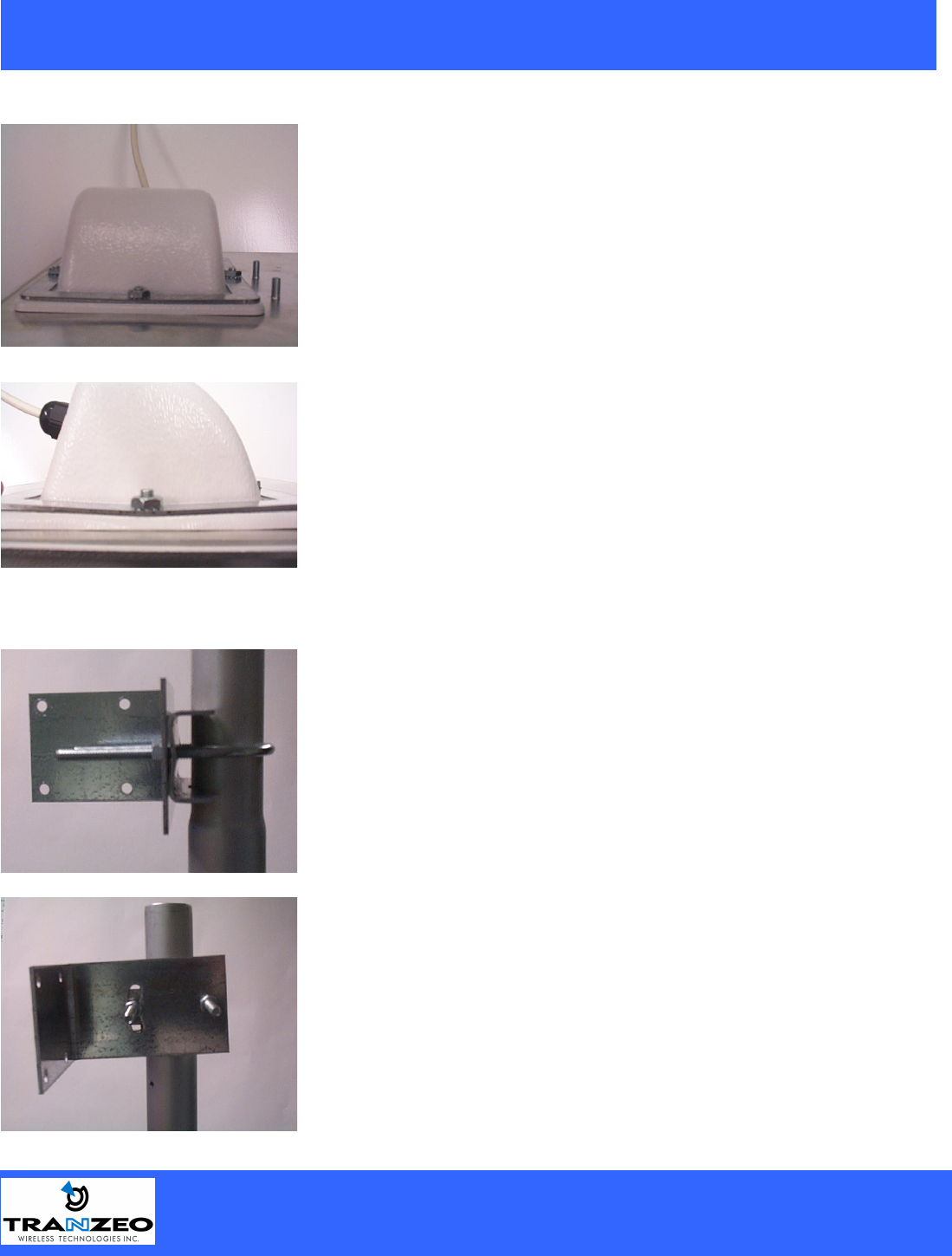
Step 7
Attaching the Mounting Bracket
Place the Ethernet boot over the 4 Screw Posts. The screws
should just barely clear the tightening bracket. Apply 4
Keep nuts to the screw posts and tighten until the gasket
makes full contact with the Ethernet boot. Do not over
tighten.
This is an example of over tightening. Over tightening
connections like this may crack the boot and will
compromise the gasket seal. Over tightening is not covered
by warranty.
As shown below, the U-Bolt is designed to mount around a
pole. Tighten bolts sufficiently to prevent any movement.
Down or up tilt can be adjusted by swinging the unit before
tightening the U-Bolt.
20155 Stewart Crescent,
Maple Ridge, B.C. Canada V2X 0T6
Phone (604) 460-6002 Fax (604) 460-6005
www.tranzeo.com
Page 9 of 24 3/10/2005
Grounding the Antenna
Using a #6 Green grounding wire, connect the Grounding Lug on the radio to a proper ground. See APPENDIX
A Lighting Information for more information.
Connect the Power Cable
Connect the power adapter to the power socket on the
Power over Ethernet Adaptor, and plug the other end of
the power into an electrical outlet. Plug the RJ-45
Cable from the unit into the POE. The Station Adaptor
will be powered on and the power indicator on the top
panel will turn on.
NOTE: ONLY use the power adapter supplied with the
Access Point. Otherwise, the product may be damaged.
This unit must be grounded. Connect the green
Grounding cable to a known good earth ground, as
outlined in the National Electrical Code.
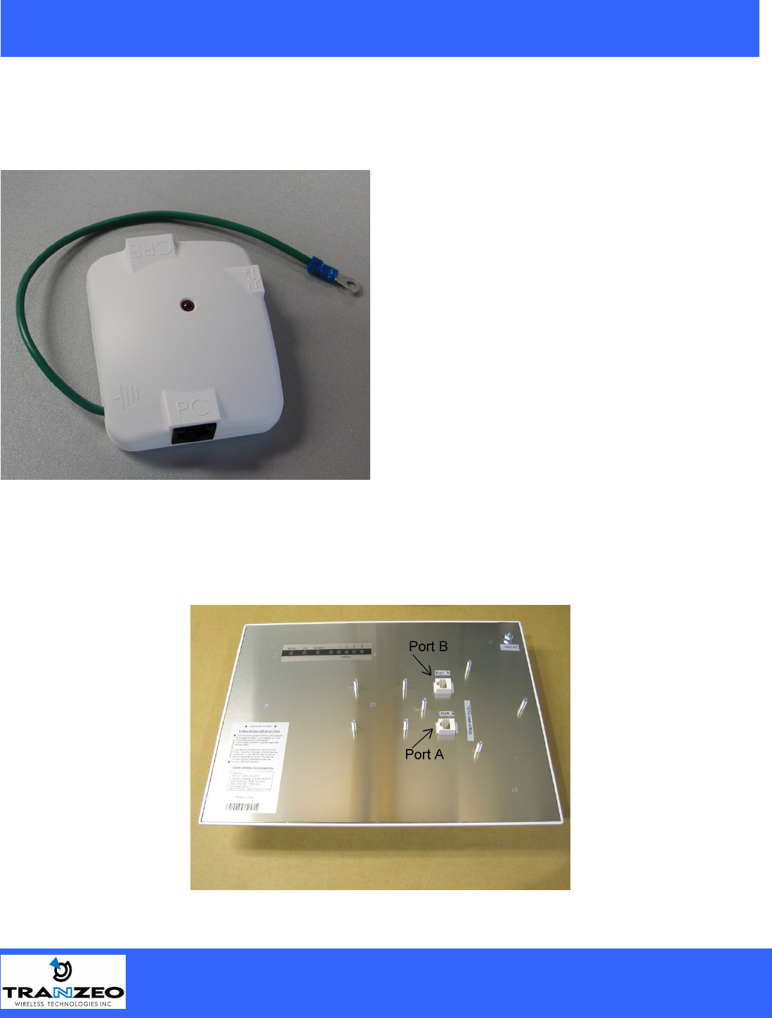
Dual Ethernet Ports
The TR-6000 has two Ethernet port available. Port A is used to connect to the radio in the radio in the case.
Port B is used to power and provide Ethernet connectivity to additional devices. This allows for the chaining of
multiple devices together.
20155 Stewart Crescent,
Maple Ridge, B.C. Canada V2X 0T6
Phone (604) 460-6002 Fax (604) 460-6005
www.tranzeo.com
Page 10 of 24 3/10/2005
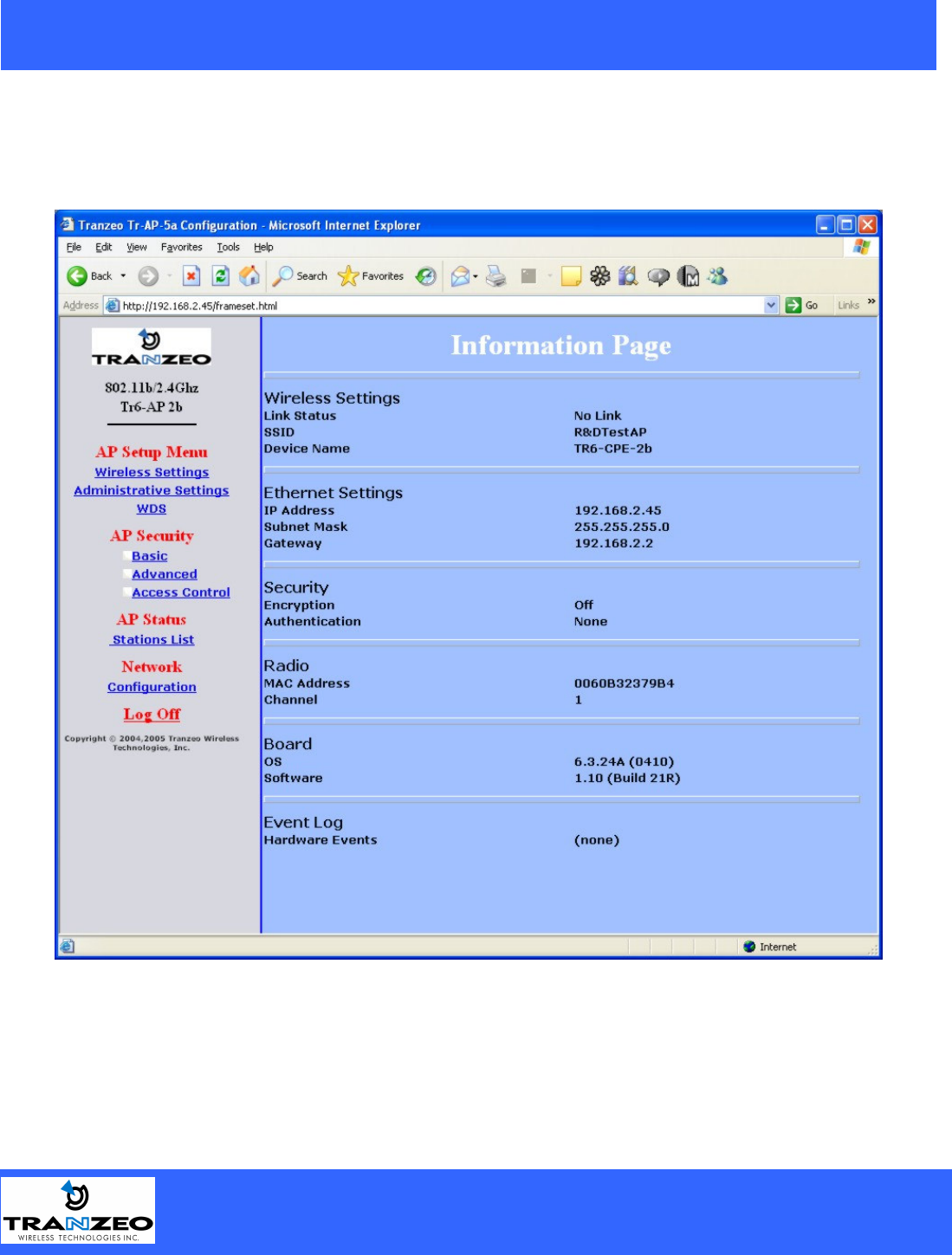
HTML Interface – Information Page
NOTE: The default IP address is 192.168.1.100
The default User Name is admin
The default Password is default
In the frame on the left, select the option you wish to configure.
20155 Stewart Crescent,
Maple Ridge, B.C. Canada V2X 0T6
Phone (604) 460-6002 Fax (604) 460-6005
www.tranzeo.com
Page 11 of 24 3/10/2005
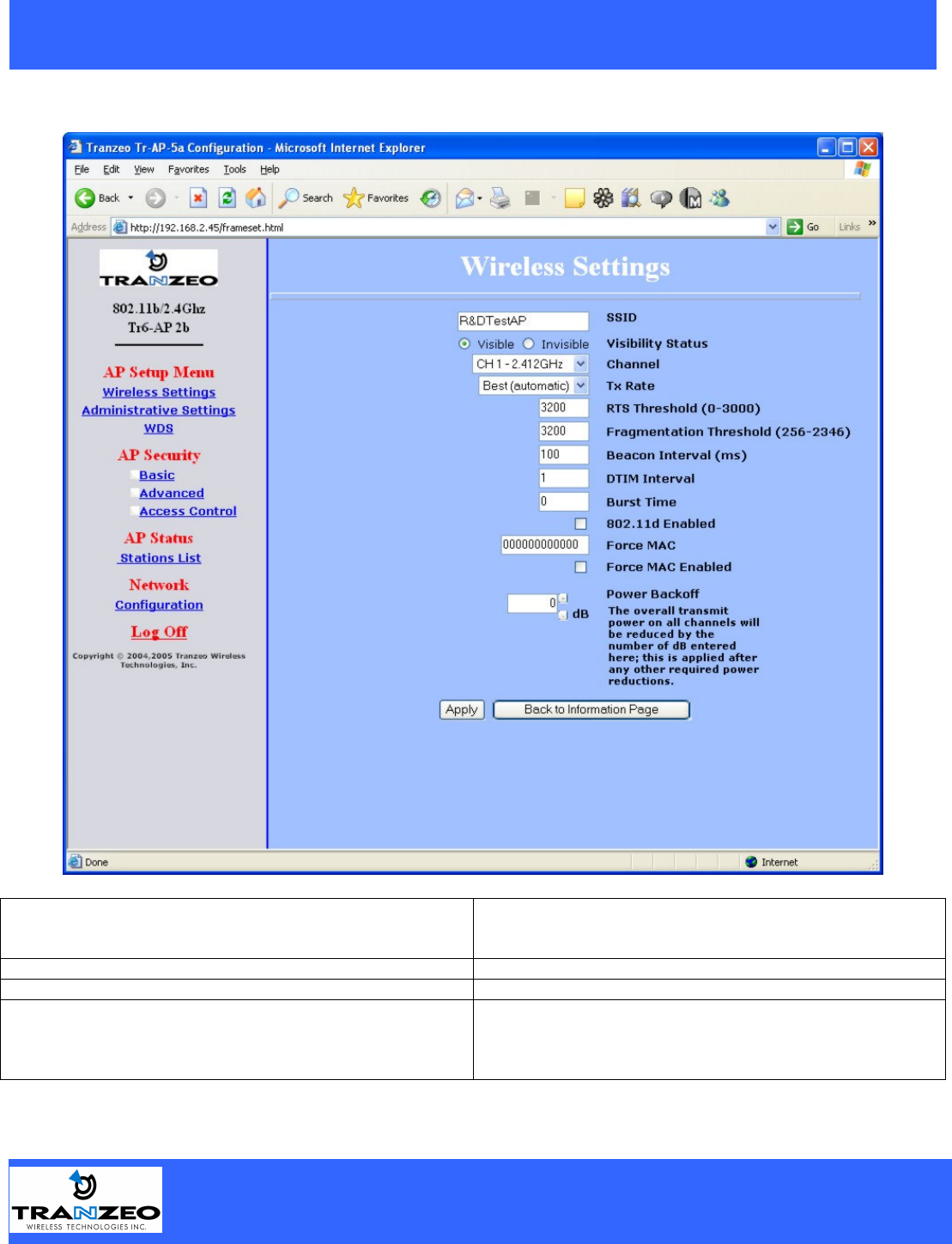
Wireless Settings
SSID The SSID is a unique ID given to an Access Point. Wireless
clients associating to the Access Point must have the same SSID.
The SSID can have up to 32 characters.
Visibility Status Makes the AP visible or invisible to clients.
Channel Sets the channel that the AP and clients will use
TX Rate The rate at which the radio will communicate with the clients.
NOTE: Setting this rate below the maximum possible does not
limit bandwidth, and often has a negative impact on the operation
of your network.

20155 Stewart Crescent,
Maple Ridge, B.C. Canada V2X 0T6
Phone (604) 460-6002 Fax (604) 460-6005
www.tranzeo.com
Page 12 of 24 3/10/2005
RTS Threshold (0-3000) Select RTS that works best in your location. A general rule of
thumb is the more clients you have, the lower the value should be
set.
Fragmentation Threshold (256-2346) Select Fragmentation that works best in your location. The lower
the Fragmentation, the smaller the packets.
Beacon Interval Sets the rate at which the AP will broadcast its location.
DTIM Interval Sets the DTIM Interval.
Burst Time Sets the Burst time
802.11d Enabled Enable 802.11d.
Force MAC
Force MAC Enabled
Power Backoff Power reduction in dB