Tranzeo Wireless Technologies TR-AP5A-N WIRELESS NETWORKING DEVICE User Manual ap 5a product manual 1
Tranzeo Wireless Technologies, Inc WIRELESS NETWORKING DEVICE ap 5a product manual 1
USERS MANUAL


20155 Stewart Crescent,
Maple Ridge, B.C. Canada V2X 0T6
Phone (604) 460-6002 Fax (604) 460-6005
www.tranzeo.com
Revision 11/30/2004 Build 22 Page 2 of 2
!"#$%!&'#() *"+##()#")#,*(,-.%(,)./.'&012!) ) #0!'!)"-.3*0*"",!4!)*0,#5!/#"&%3"%*()).&*3)
.-) #%0#" #"#0!'!)"*3#,#"!4(#,).&3.5!,#3#*".(*+0#&3.)#/)!.(*4*!(") *3'-%0!()#3-#3#(/#2 #(
) ##$%!&'#()!".*)#,!(*/.''#3/!*0#(5!3.('#()
!"#$%!&'#()4#(#3*)#"%"#"*(,/*(3*,!*)#3*,!.-3#$%#(/1#(#341*(,!-(.)!(")*00#,*(,%"#,!(*//.3,*(/#
2!) ) #!(")3%/)!.('*(%*0'*1/*%"# *3'-%0!()#3-#3#(/#).3*,!./.''%(!/*)!.(
*)!.(.-) !"#$%!&'#()!(3#"!,#()!*0*3#*!"0!6#01)./*%"# *3'-%0!()#3-#3#(/#!(2 !/ /*"#) #%"#32!00+#
3#$%!3#,)./.33#/)) #!()#3-#3#(/#*)) !".2(#7&#("#
# %"#3 " .%0, (.) '.,!-1 .3 / *(4# ) !" #$%!&'#() 2!) .%) 23!))#( *&&3.5*0 -3.' 3*(8#. !3#0#""
9.,!-!/*)!.(/.%0,5.!,*%) .3!)1).%"#) !"#$%!&'#()
.3) #"*-#)13#*".("&#.&0#" .%0,(.)2.36!(*"!)%*)!.(2 !/ 7&."%3#0!'!)"+##7/##,#,.&3#5#()
) #"!)%*)!.( *&&#(!(4&#.&0#2 .2.362!) ) #*()#((*" .%0,+#*2*3#.-) #-.00.2!(43%0#"
(")*00) #*()#((*!(*0./*)!.(2 #3#*,!")*(/#.-:/'-3.') #*()#((*'*1+#'*!()*!(#,
!0#!(")*00!(4) #*()#((*!() #0./*)!.(&0#*"#,.(.))%3(.() #&.2#3.-2!3#0#""/*3,
; !0#) #,#5!/#!"2.36!(4&0#*"#,.(.)/.()*/)) #*()#((*
<#7&."%3#= #*()#((*%"#,-.3) !")3*("'!))#3'%")(.)+#/.0./*)#,.3.*)!(4!(/.(>%(/)!.(
2!) *(1.) #3*()#((*.3)3*("'!))#3?
!"
9 @
=
• !"*()#((*A"43.%(,!(4"1")#''%")+#!(")*00#,*//.3,!(4).3)!/0#BBB.-) #*)!.(*00#/)3!/.,#
C.D::;-1.% *5#*(1$%#")!.(".3,.%+)"*+.%)1.%3*()#((*43.%(,!(4"1")#'/.()*/)*0./*00!/#("#,
#0#/)3!/!*(
• #5#3*))*/ ) #3.%(,!(4 !3#2 !0#) #,#5!/#!"&.2#3#,
• -) #43.%(,!").+#*))*/ #,).*(#7!")!(4#0#/)3!/*0/!3/%!))%3(.--) #/!3/%!)+#-.3#*))*/ !(4) #2!3#
• "#) #3*(8#..(012!) *&&3.5#,3*(8#.'.,#0"
• #5#3!(")*00*,!.$%!&'#()"%34#"%&&3#"".3".30!4 )(!(4&3.)#/)!.(,%3!(4*").3'
#$
#6#1).*!4 )(!(43.)#/)!.(!"&3.5!,!(4* *3'0#""3.%)#-.30!4 )(!(4).3#*/ 43.%(, #"1")#'" .%0,(.)+#,#"!4(#,).
*))3*/)0!4 )(!(4(.3/*(!)3#�!4 )(!(4*)!.(*0)*)#*(,0./*0/.,#"*3#,#"!4(#,).&3.)#/)0!-#0!'+*(,&3.)1*(,'%")*02*1"
+#.+#1#,
%&!'(!)))&)))&)*)&%&+
+!&+

20155 Stewart Crescent,
Maple Ridge, B.C. Canada V2X 0T6
Phone (604) 460-6002 Fax (604) 460-6005
www.tranzeo.com
Revision 11/30/2004 Build 22 Page 3 of 3
, !-!&
, !-!&
Introduction
This next-generation wireless LAN device – the TRANZEO TR-AP-5a, brings Ethernet-like performance to the
wireless realm. Fully compliant with the IEEE802.11a standard, the TRANZEO TR-AP-5a also provides powerful
features such as the Internet-based configuration utility, and WEP and WPA security. Maximize network efficiency
while minimizing your network investment and maintenance costs.
, !-!&
Hardware Installation
Product Kit
Before installation, make sure that you have the following items:
The TR AP-5a x 1
DC Power Adapter x 1
Power over Ethernet Adapter x 1
Ethernet Boot x 1
Mounting Bracket x 1
Ket Nuts (With Washer Attached) x 8
U-Bolt w/ 2 Nuts x 1
RJ-45 Patch Cable x 1
Spare Ethernet Boot Gasket x 1
Optional: Ethernet Boot Tightening Bracket x 1
If any of the above items is not included or damaged, please contact your local dealer for support.
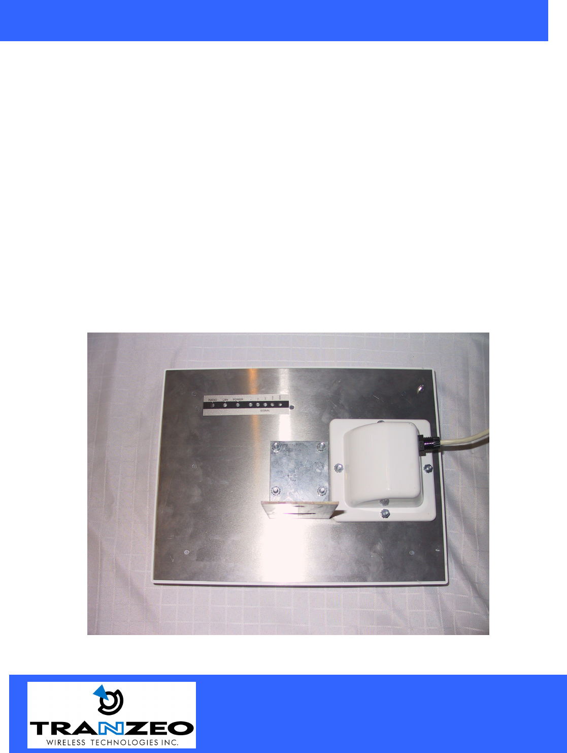
Mechanical Description
LED panel of the Wireless LAN Smart Access Point:
The following table provides an overview of each LED activity:
LED Definition Activity Description
Label Color Indicators
POWER RED On: Powered On
Off: No Power
LAN Amber/Green*
On: Ethernet Link
Flashing : Ethernet Traffic
Off: No Ethernet Link
Radio Amber
On: Radio Link
Flashing Radio Activity
Off: No Radio Link
*Only one of the two colors will be shown. Actual color will vary between units.

20155 Stewart Crescent,
Maple Ridge, B.C. Canada V2X 0T6
Phone (604) 460-6002 Fax (604) 460-6005
www.tranzeo.com
Revision 11/30/2004 Build 22 Page 4 of 4
Power Supply: ONLY use the power adapter supplied with the TR- AP-5a. Otherwise, the product may be
damaged.
20155 Stewart Crescent,
Maple Ridge, B.C. Canada V2X 0T6
Phone (604) 460-6002 Fax (604) 460-6005
www.tranzeo.com
Revision 11/30/2004 Build 22 Page 5 of 5
2-4 Hardware Installations
Take the following steps to set up your TR-AP-5a.
Site Selection: Before installation, determine the TR-AP-5a Units location. Proper placement of the unit is
critical to ensure optimum radio range and performance. You should perform a Site Survey to choose a proper
placement for your unit. Place your unit within the line of sight of the Access Point. Obstructions may impede
performance of the unit.
Tools Required to Install
• One 3/8 wrench
• One 3/4 wrench
• One RJ-45 Crimper
• A suitable length of Cat 5 Cable to bring the signal from the unit to the Power over Ethernet Adaptor
• 2 RJ-45 Jacks
Before installing, you must determine if you will be installing the unit in a horizontal or vertical orientation.
The TR-AP-5a model can be mounted in either orientation. The Ethernet boot should always be placed so that
the cable runs toward the ground for maximum environmental protection.

20155 Stewart Crescent,
Maple Ridge, B.C. Canada V2X 0T6
Phone (604) 460-6002 Fax (604) 460-6005
www.tranzeo.com
Revision 11/30/2004 Build 22 Page 6 of 6
20155 Stewart Crescent,
Maple Ridge, B.C. Canada V2X 0T6
Phone (604) 460-6002 Fax (604) 460-6005
www.tranzeo.com
Revision 11/30/2004 Build 22 Page 7 of 7
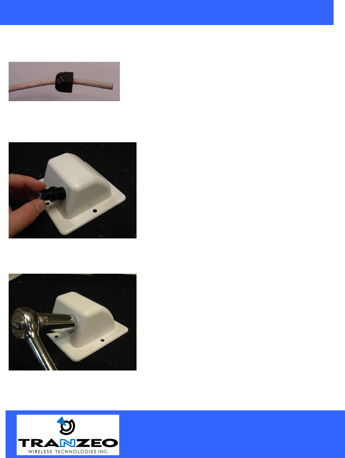
Connecting the Ethernet Cable
Step 1
Place the Ethernet Boot Cover over the end of your Cat 5 Cable. Attach
the sticky side of the gasket to the underside of the Ethernet Boot.
Step 2
Step 3
Tighten using a ¾” wrench or socket. Tighten until the
Cable Lock touches the Boot as shown in Step 3.
USE HAND TOOLS ONLY. DO NOT OVERTIGHTEN
as you may damage the environment seal.
Attach Ethernet Cable Lock on side of the Ethernet Boot.
This is easiest to do before you attach the RJ-45 Jack.
20155 Stewart Crescent,
Maple Ridge, B.C. Canada V2X 0T6
Phone (604) 460-6002 Fax (604) 460-6005
www.tranzeo.com
Revision 11/30/2004 Build 22 Page 8 of 8
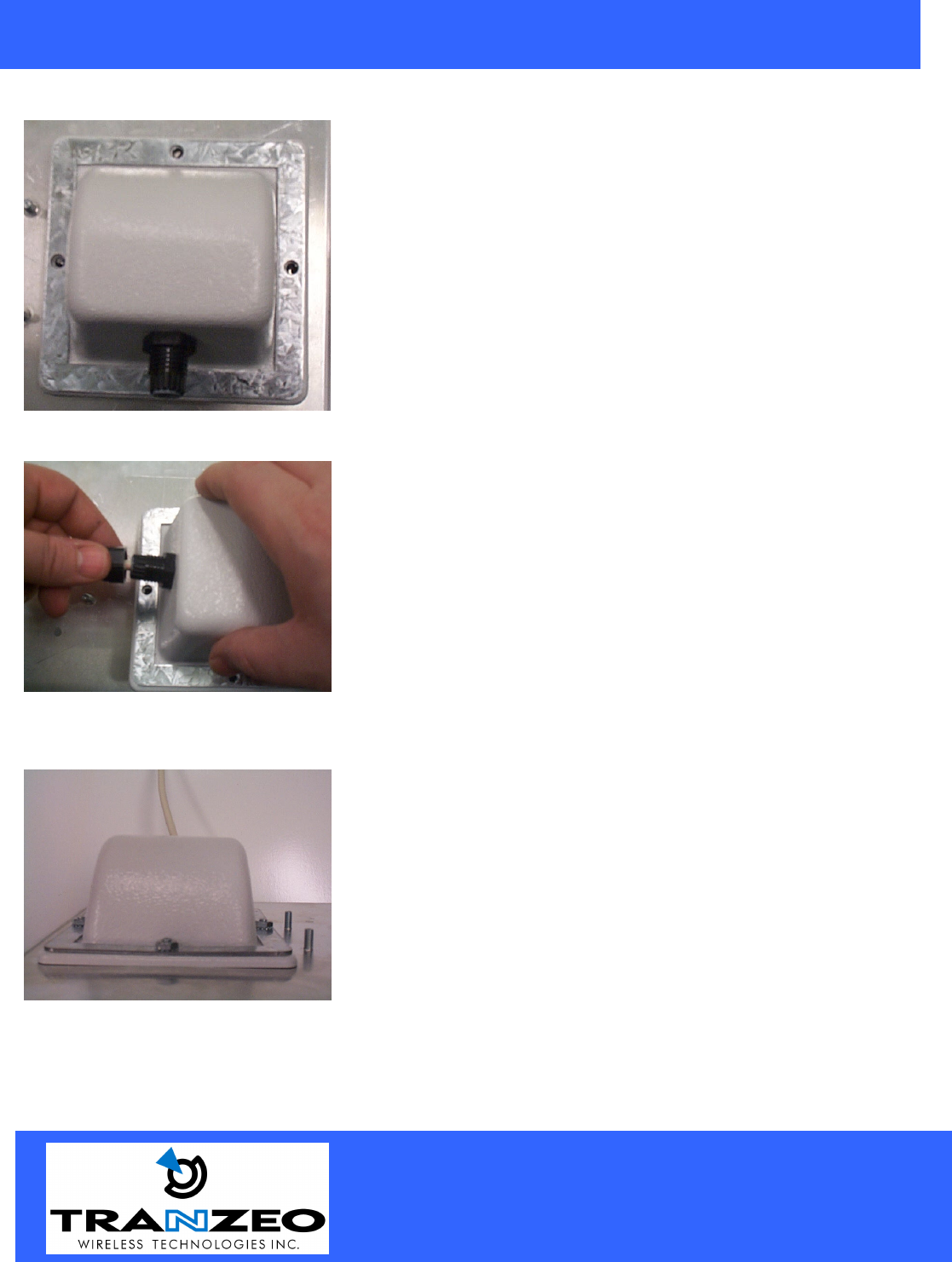
Step 4
Step 5
Step 6
Place the Ethernet boot over the 4 Screw Posts. The screws should just
barely clear the tightening bracket. Apply 4 Ket nuts to the screw posts
and tighten until the gasket makes full contact with the Ethernet boot.
Do not over tighten.
Attach optional tightening bracket on top of the Ethernet
Boot. This is easiest to do before you attach the CAT 5
cable. The Gasket must be attached to the Boot so that it
sits between the radio and the boot.
Insert the Cat 5 Cable and tighten the Boot Cover. Be sure
to pull enough cable through to reach the RJ-4
5 connector
with an RJ-
45 jack attached. Attach tightening bracket on
top of the Ethernet Boot. This is easiest to do before you
attach the CAT 5 cable. The Gasket must be attached to the
Boot so that it sits between the radio and the boot.
Hand tight
en only. DO NOT OVERTIGHTEN as you may
damage the environment seal.
20155 Stewart Crescent,
Maple Ridge, B.C. Canada V2X 0T6
Phone (604) 460-6002 Fax (604) 460-6005
www.tranzeo.com
Revision 11/30/2004 Build 22 Page 9 of 9
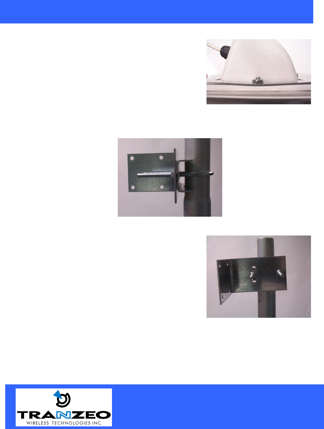
This is an example of over tightening. Over tightening
connections like this may crack the boot and will
compromise the gasket seal. Over tightening is not covered
by warranty.
Attaching the Mounting Bracket
As shown below, the U-Bolt is designed to mount around a pole.
Tighten bolts sufficiently to prevent any movement.
Down or up tilt can be adjusted by swinging the unit before
tightening the U-Bolt.
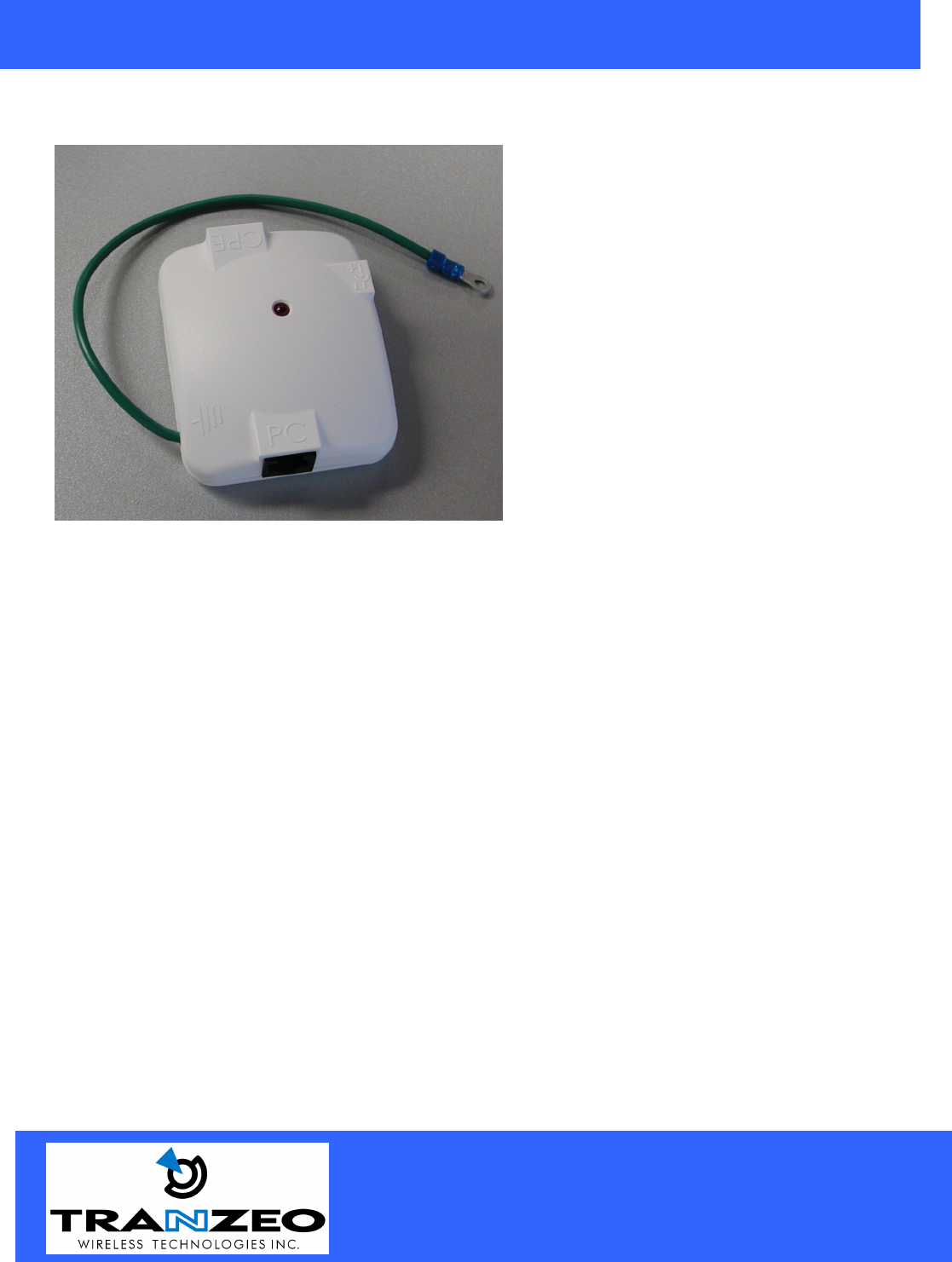
Grounding the Antenna
Using a #6 Green grounding wire, connect the Grounding Lug on the radio to a proper ground. See APPENDIX
A Lighting Information for more information.
20155 Stewart Crescent,
Maple Ridge, B.C. Canada V2X 0T6
Phone (604) 460-6002 Fax (604) 460-6005
www.tranzeo.com
Revision 11/30/2004 Build 22 Page 10 of 10
Connect the Power Cable
Connect the power adapter to the power socket on
the Power over Ethernet Adaptor, and plug the
other end of the power into an electrical outlet. Plug
the RJ-45 Cable from the unit into the POE. The
Station Adaptor will be powered on and the power
indicator on the top panel will turn on.
NOTE: ONLY use the power adapter supplied with
the Access Point. Otherwise, the product may be
damaged.
This unit must be grounded. Connect the green
Grounding cable to a known good earth ground, as
outlined in the National Electrical Code.
20155 Stewart Crescent,
Maple Ridge, B.C. Canada V2X 0T6
Phone (604) 460-6002 Fax (604) 460-6005
www.tranzeo.com
Revision 11/30/2004 Build 22 Page 11 of 11
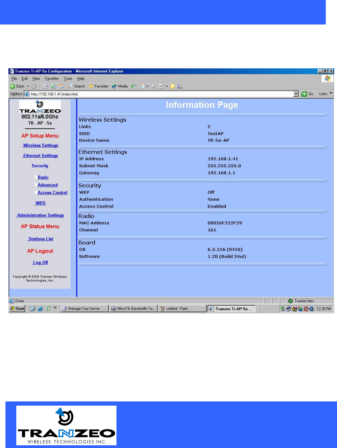
HTML Interface
NOTE: The default IP address is 192.168.1.100
Select the option in the frame on the left you wish to configure.
20155 Stewart Crescent,
Maple Ridge, B.C. Canada V2X 0T6
Phone (604) 460-6002 Fax (604) 460-6005
www.tranzeo.com
Revision 11/30/2004 Build 22 Page 12 of 12
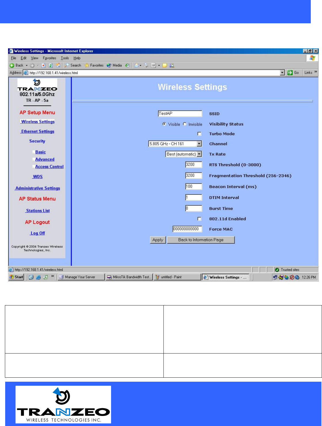
Wireless Settings
SSID The SSID is a unique ID given to an Access Point.
Wireless clients associating to the Access Point must
have the same SSID. The SSID can have up to 32
characters.
HINT: Entering “none” the field allows the unit to
see all AP’s in the area.
Turbo Mode When using turbo mode, the other device must also
support Turbo Mode. Also, the channel must be set
manually on the AP.
20155 Stewart Crescent,
Maple Ridge, B.C. Canada V2X 0T6
Phone (604) 460-6002 Fax (604) 460-6005
www.tranzeo.com
Revision 11/30/2004 Build 22 Page 13 of 13
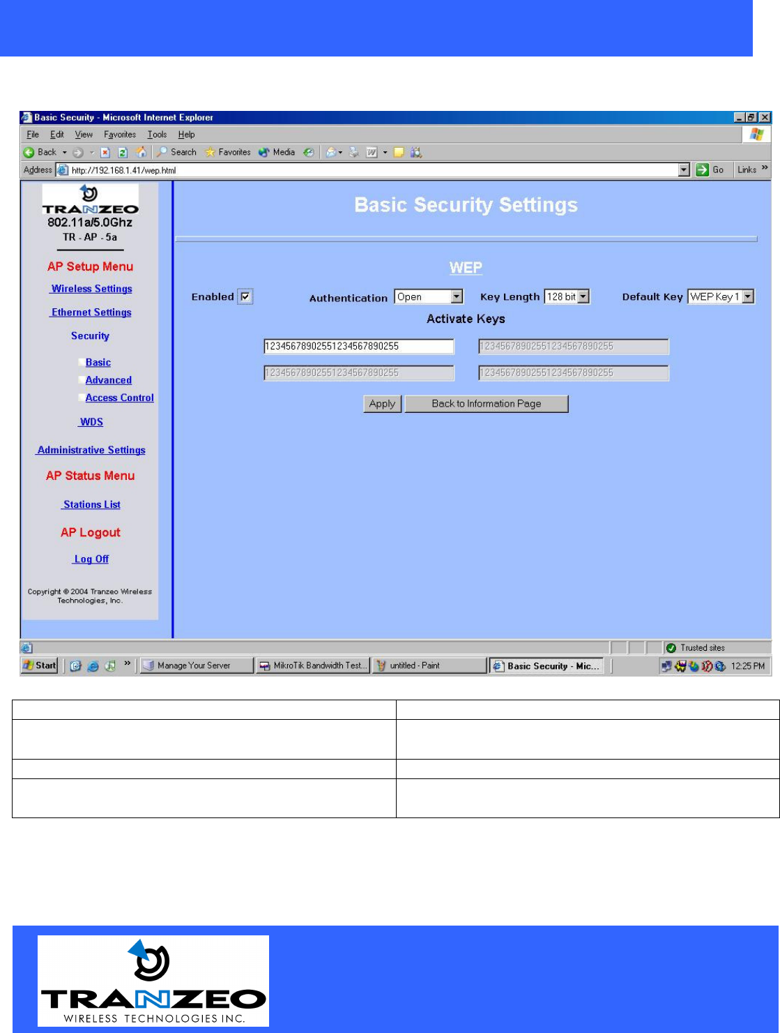
Security Basic
Enabled Turn On WEP
Key Length Level of Encryption.
NOTE: 64 bit is called 40 bit on some systems
Shared Key Authentication Turn on Shared Key Authentication
Keys Enter your WEP keys. NOTE: Keys must be
entered in HEX only.
20155 Stewart Crescent,
Maple Ridge, B.C. Canada V2X 0T6
Phone (604) 460-6002 Fax (604) 460-6005
www.tranzeo.com
Revision 11/30/2004 Build 22 Page 14 of 14
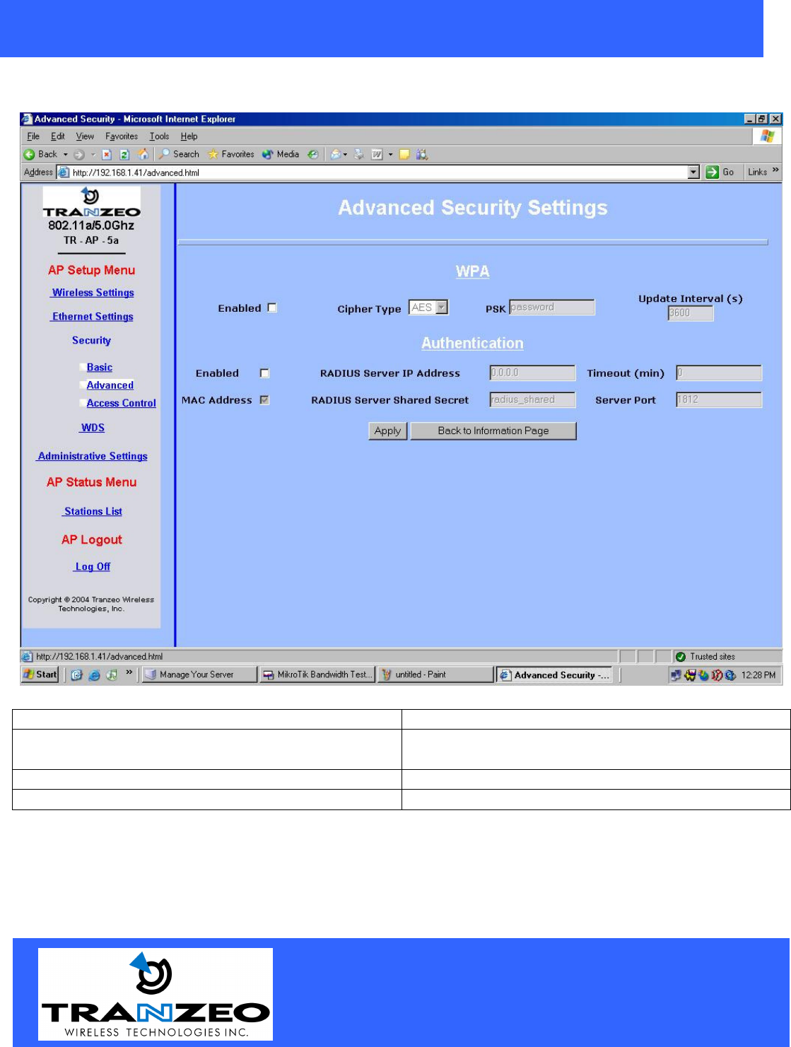
Security Advanced
Enabled Turn On WPA
Encryption Type Level of Encryption.
TKIP or AES
Enabled Authentication 802.1x for Radius Server
20155 Stewart Crescent,
Maple Ridge, B.C. Canada V2X 0T6
Phone (604) 460-6002 Fax (604) 460-6005
www.tranzeo.com
Revision 11/30/2004 Build 22 Page 15 of 15
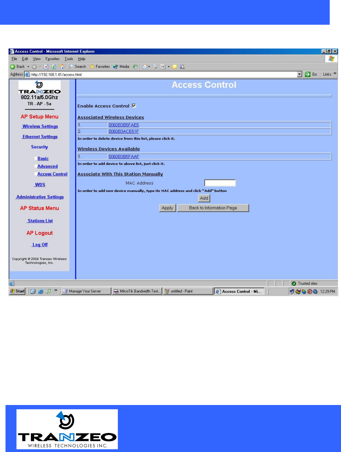
Access Control
Click on stations in Wireless Devices Available to enter station in Allowed Stations or
Click in Associated Wireless Devices to delete it.
20155 Stewart Crescent,
Maple Ridge, B.C. Canada V2X 0T6
Phone (604) 460-6002 Fax (604) 460-6005
www.tranzeo.com
Revision 11/30/2004 Build 22 Page 16 of 16
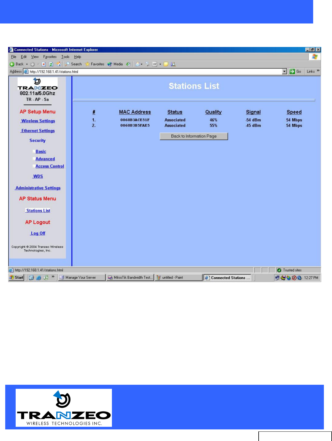
Station List
Radio for Technical Support
issues.
20155 Stewart Crescent,
Maple Ridge, B.C. Canada V2X 0T6
Phone (604) 460-6002 Fax (604) 460-6005
www.tranzeo.com
Revision 11/30/2004 Build 22 Page 17 of 17
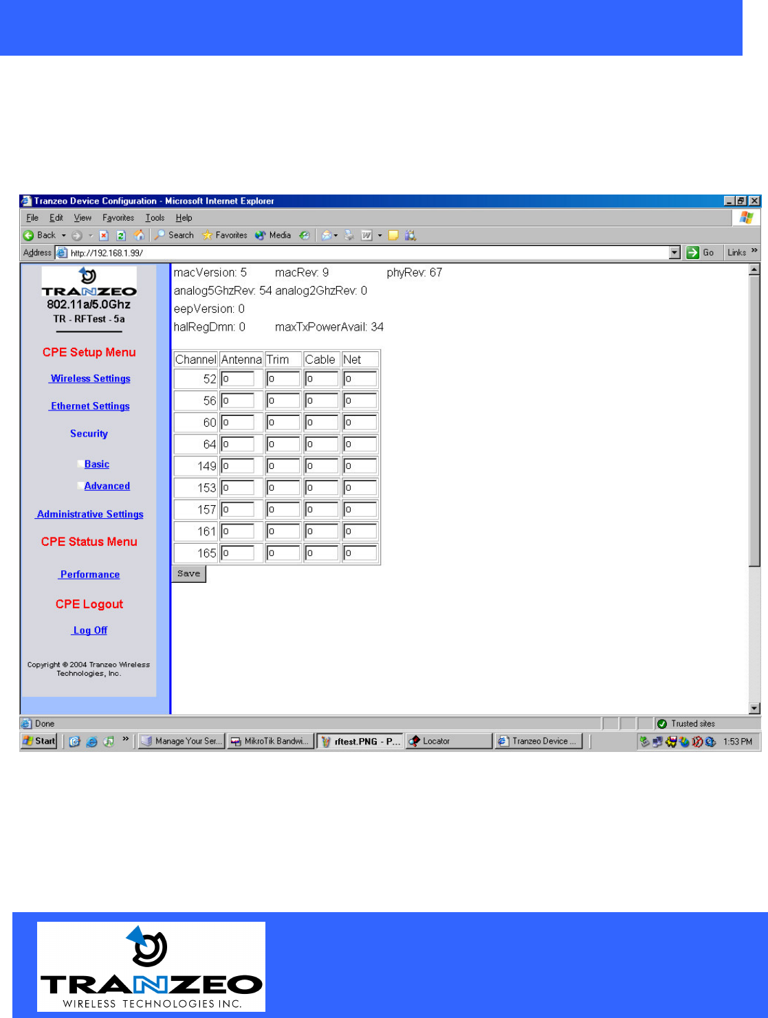
RF Setback
When using the TR-AP-5a-N the installer must set the correct power setbacks for the antenna being used by
entering the gain of the antenna into the table. On the TR-AP-5a-21 and the the TR-AP-5a-24 these setbacks
are set at the factory as the antenna is integrated.

20155 Stewart Crescent,
Maple Ridge, B.C. Canada V2X 0T6
Phone (604) 460-6002 Fax (604) 460-6005
www.tranzeo.com
Revision 11/30/2004 Build 22 Page 18 of 18
."$ /
What is a proper Ground?
This antenna must be grounded to a proper Earth Ground.
According to the The National Electrical Code Sections 810-15s and 810-21, the grounding
conductor shall be connected to the NEAREST accessible locations of the following:
a) The building / structure grounding electrode
b) The grounded interior metal water piping system
c) the power service accessible means external to enclosure
d) the metallic power service raceway
e) the service equipment enclosure
f) The grounding electrode conductor
The important thing is to connect to ground at the nearest point.
Why is coiling the LMR or CAT5 bad?
The myth is that lighting follows the path of least resistance. It actually follows the path of least impedance.
Coiling cables creates an air-wound transformer, which lowers the impedance. This means you are in fact
making your radios a more appealing target for surges.
What standard does Tranzeo Wireless equipment meet?
This radio exceeds International Standard IEC 61000-4-5 when properly grounded. For a copy of the full
testing report, see Report Number TRL090904 - Tranzeo Surge Protection board located on the Tranzeo
website.
Is lightning damaged covered by the Warranty?
No. Lightning is not covered by the warranty. If you follow the instructions, you chances of lightning damage
are greatly reduced, but nothing can protect a radio from a direct lightning strike.
20155 Stewart Crescent,
Maple Ridge, B.C. Canada V2X 0T6
Phone (604) 460-6002 Fax (604) 460-6005
www.tranzeo.com
Revision 11/30/2004 Build 22 Page 19 of 19
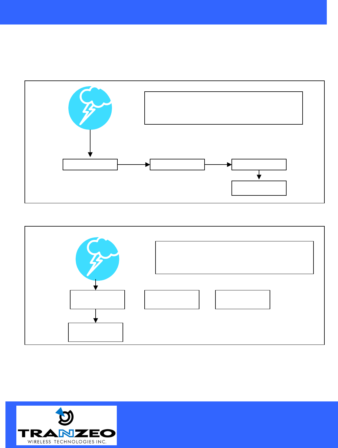
Where to Ground the device
This radio must be grounded at the Pole AND at the POE. This is because the radio is between the Exterior
Antenna and the POE ground. See the examples below
Ungrounded Radio
`
Grounded Radio
Antenna
POE
Radio
Ground
An ungrounded radio causes the surge to pass
through the radio. In this case the radio most
likely will be damaged.
POE Antenna Radio
Ground
An grounded radio causes the surge to pass
directly to ground, bypassing the radio.
20155 Stewart Crescent,
Maple Ridge, B.C. Canada V2X 0T6
Phone (604) 460-6002 Fax (604) 460-6005
www.tranzeo.com
Revision 11/30/2004 Build 22 Page 20 of 20
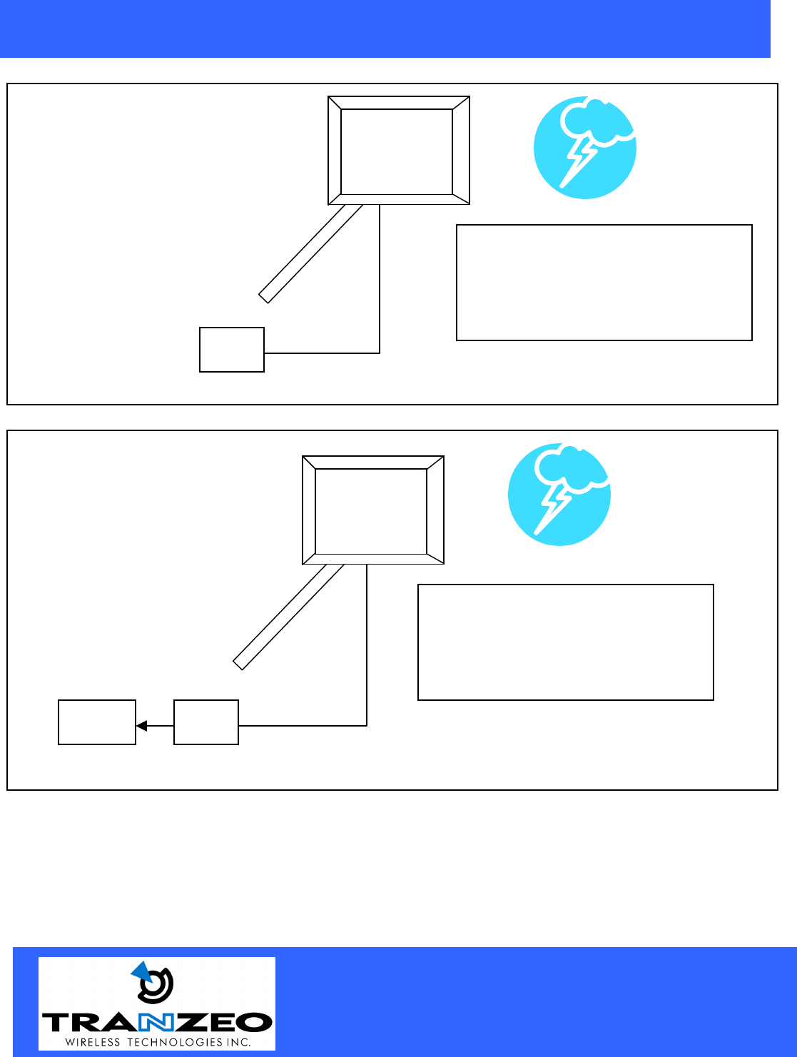
Ungrounded POE
Grounded POE
Cat 5 Cable
Mounting Pole
Mounting Pole
POE
In this case, the surg
e will be picked up
by the Cat 5 cable, and since the POE
is not grounded, the route for the surge
is through the radio to the antenna, and
out through the building.
POE
In this case, the surge will be picked up
by the Cat 5 cable, and since the POE
is grounded, the route for the surge is
through the POE to ground.
Ground
Cat 5 Cable
20155 Stewart Crescent,
Maple Ridge, B.C. Canada V2X 0T6
Phone (604) 460-6002 Fax (604) 460-6005
www.tranzeo.com
Revision 11/30/2004 Build 22 Page 21 of 21
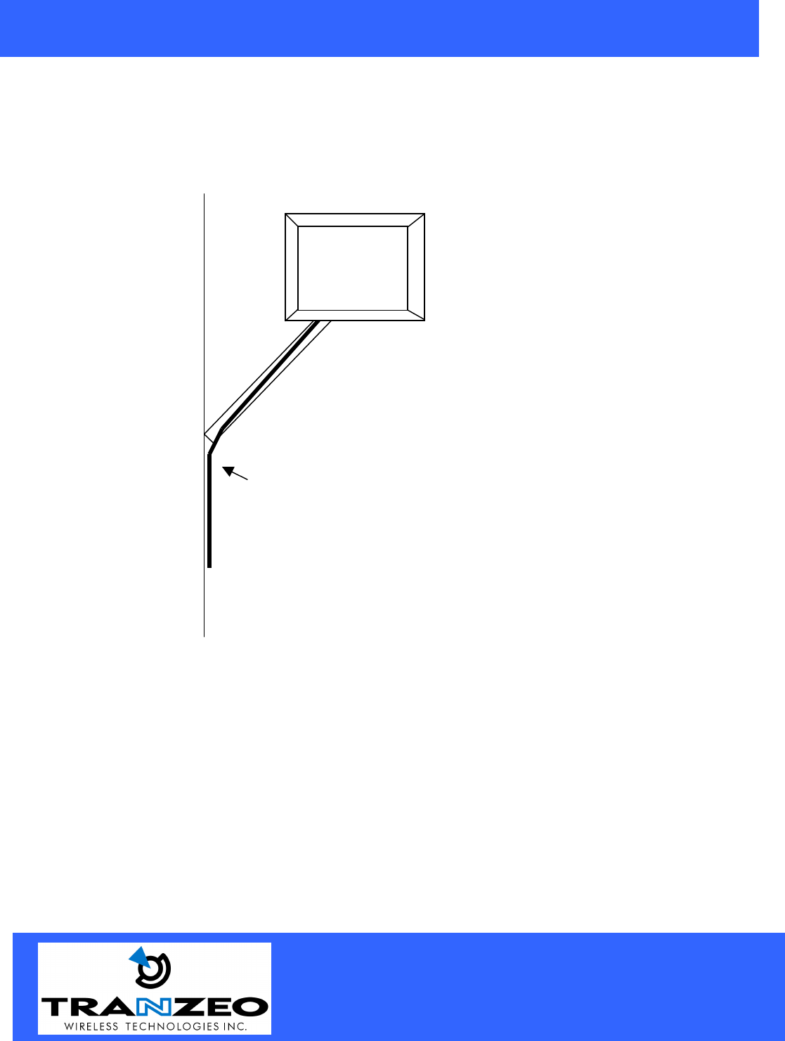
Best Practices
1) Allow try to run the Cat5 and LMR inside of the mounting pole wherever possible. This helps to
insulate the cable from any air surges.
2) Keep all runs as straight as possible. Never put a loop into the cables.
3) Test all grounds to ensure that you are using a proper Ground. If using a electrical socket for Ground,
use a socket tester, such as Radio Shack 22-141
4) Buy a copy of the National Electrical Code Guide and follow it.
5) If you are in doubt about the grounding at the location, drive your own rod and bond it to the house
ground. At least you will know that one Rod is correct in the system.
Cat 5 Cable
Building