Tranzeo Wireless Technologies TR-AP5AMP-N WIRELESS NETWORKING DEVICE User Manual ap 5amp N product manual 1
Tranzeo Wireless Technologies, Inc WIRELESS NETWORKING DEVICE ap 5amp N product manual 1
UserManual.wiki
>
Tranzeo Wireless Technologies
>
TR AP5AMP N User Manual
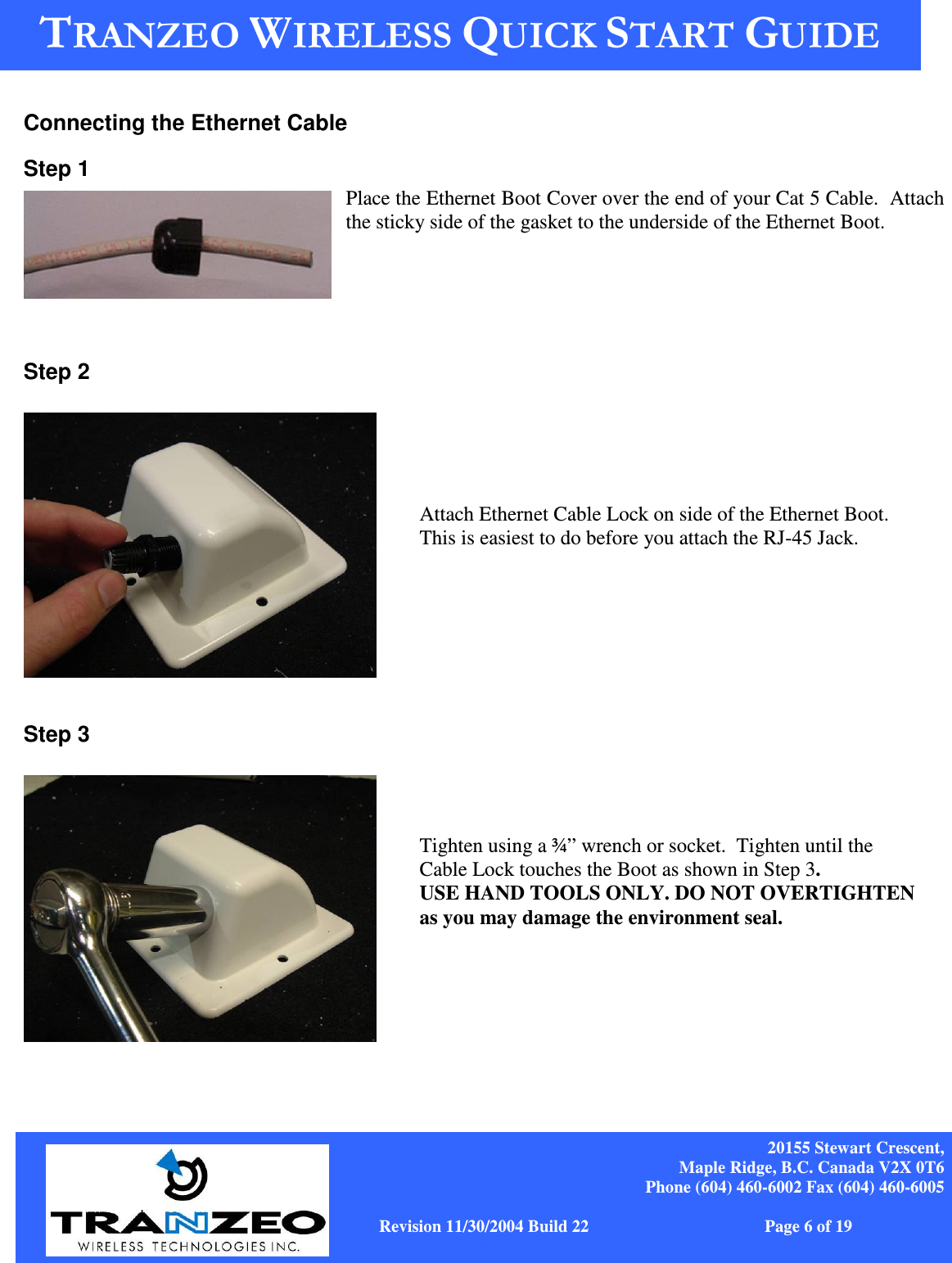
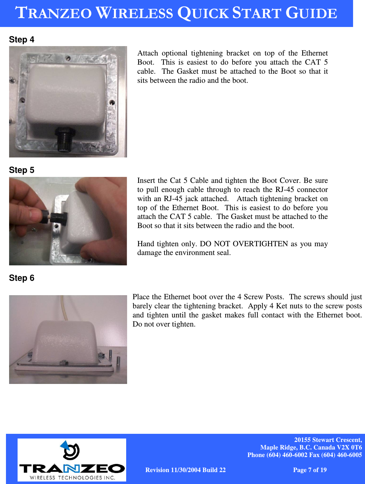
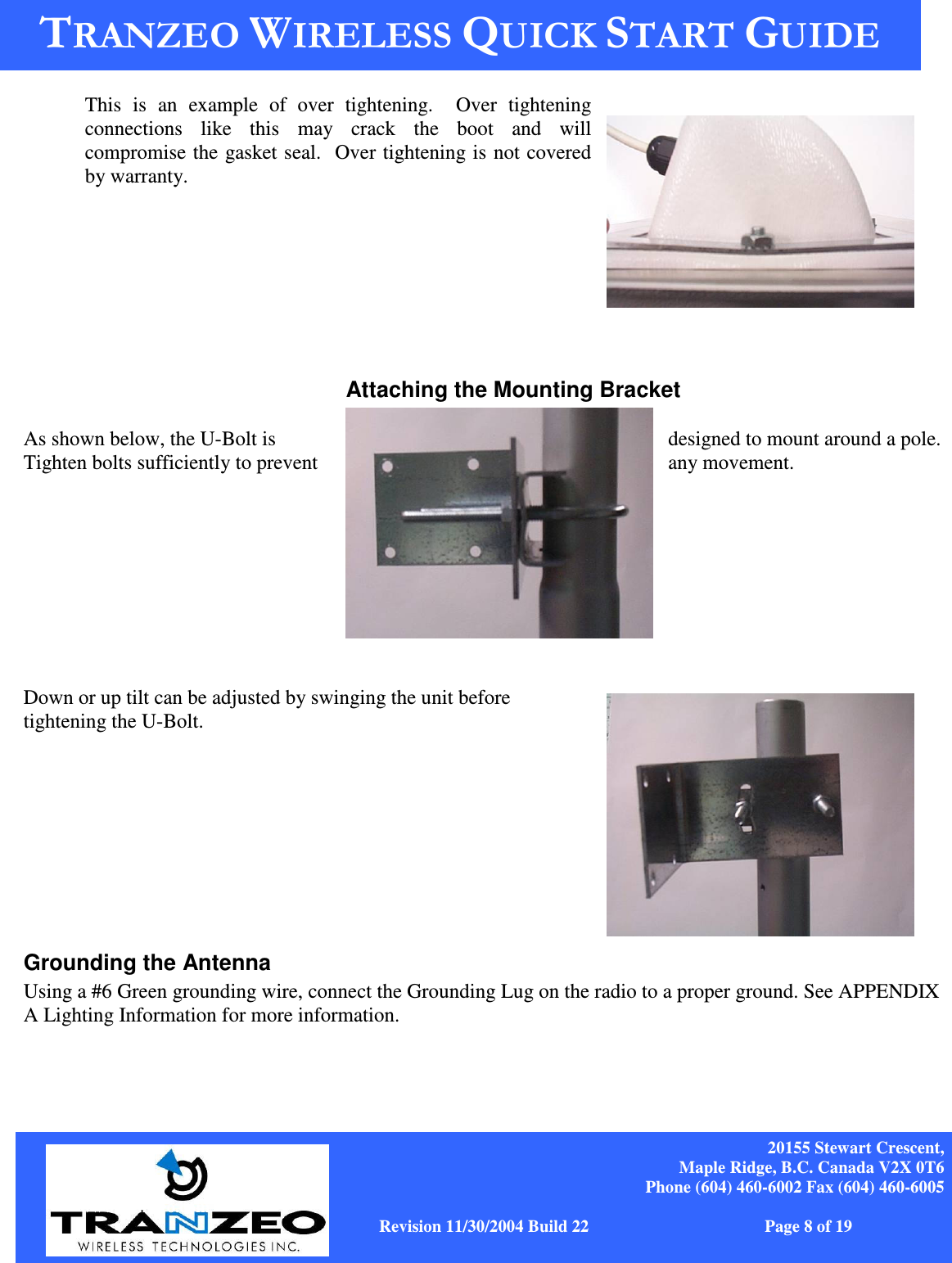
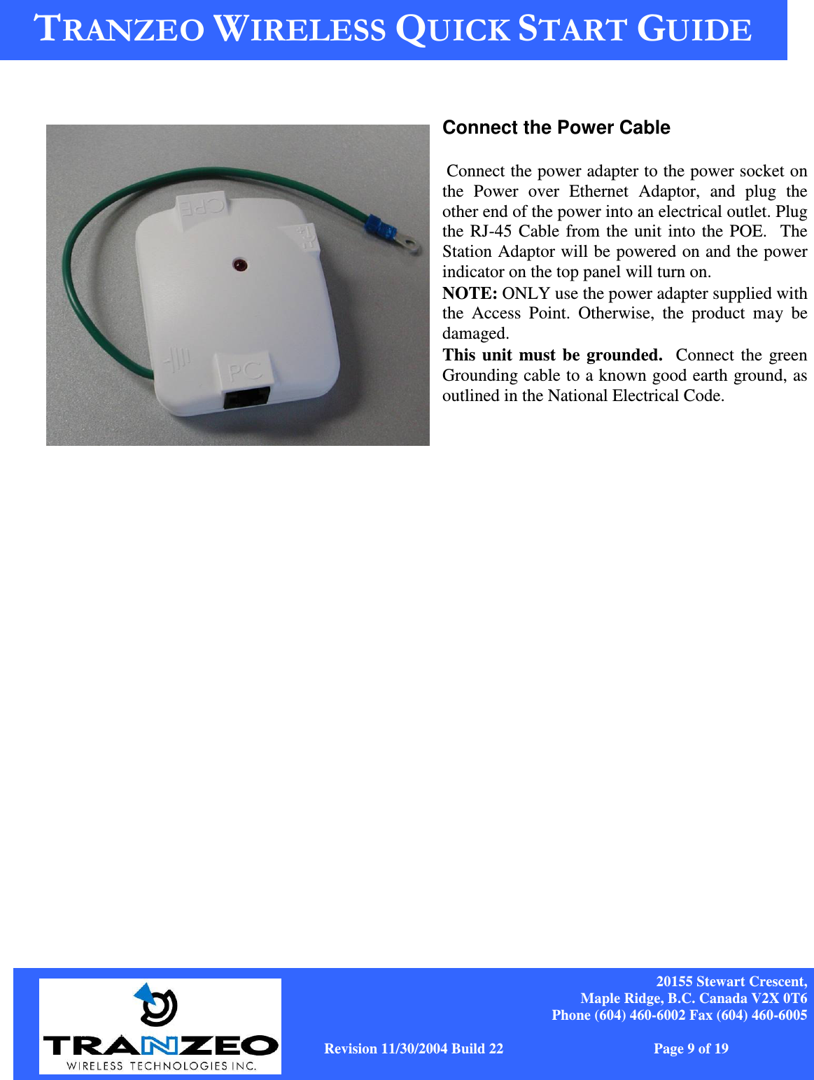
USERS MANUAL
Navigation menu
Upload a User Manual
Namespaces
Wiki Guide
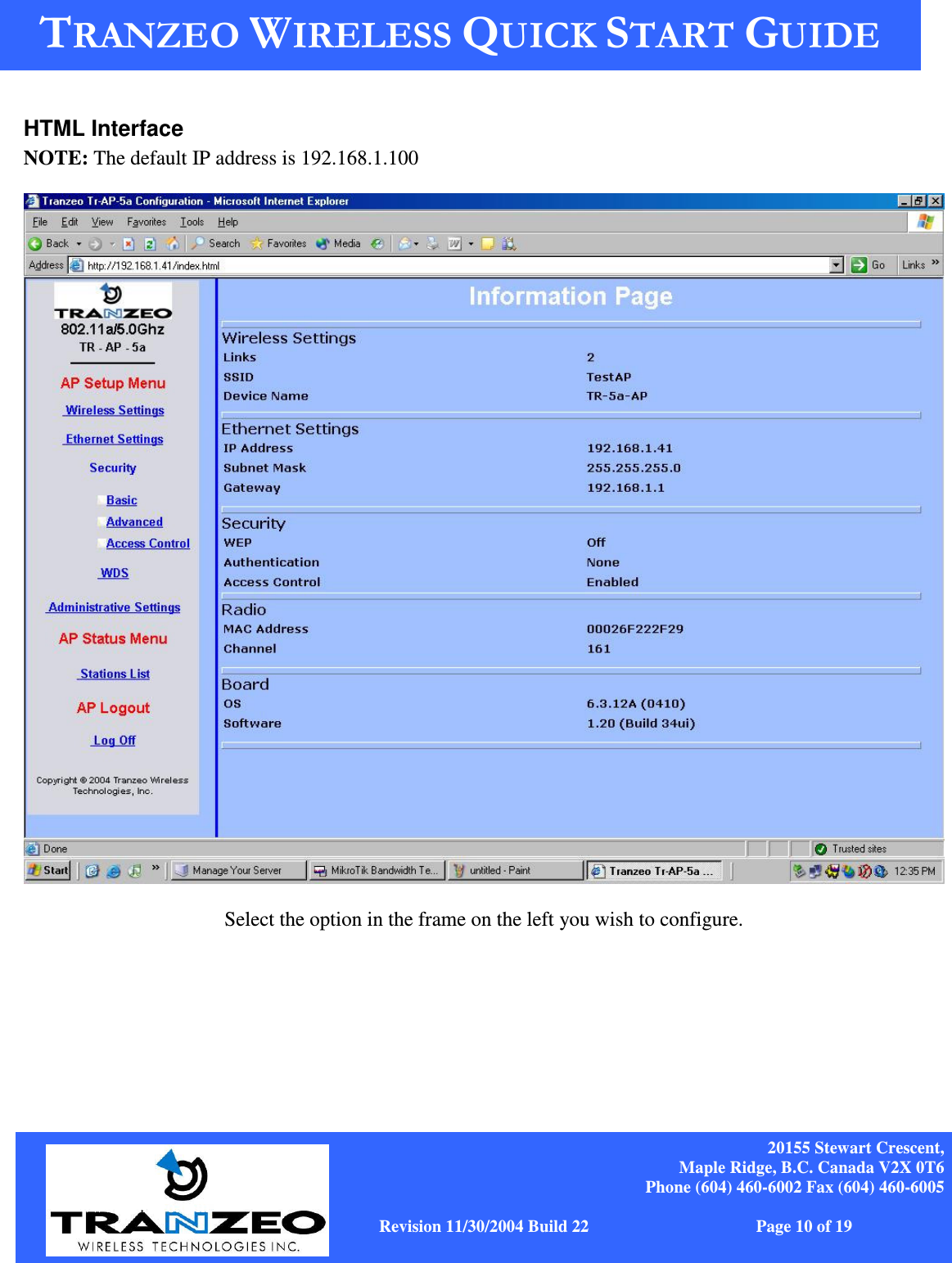
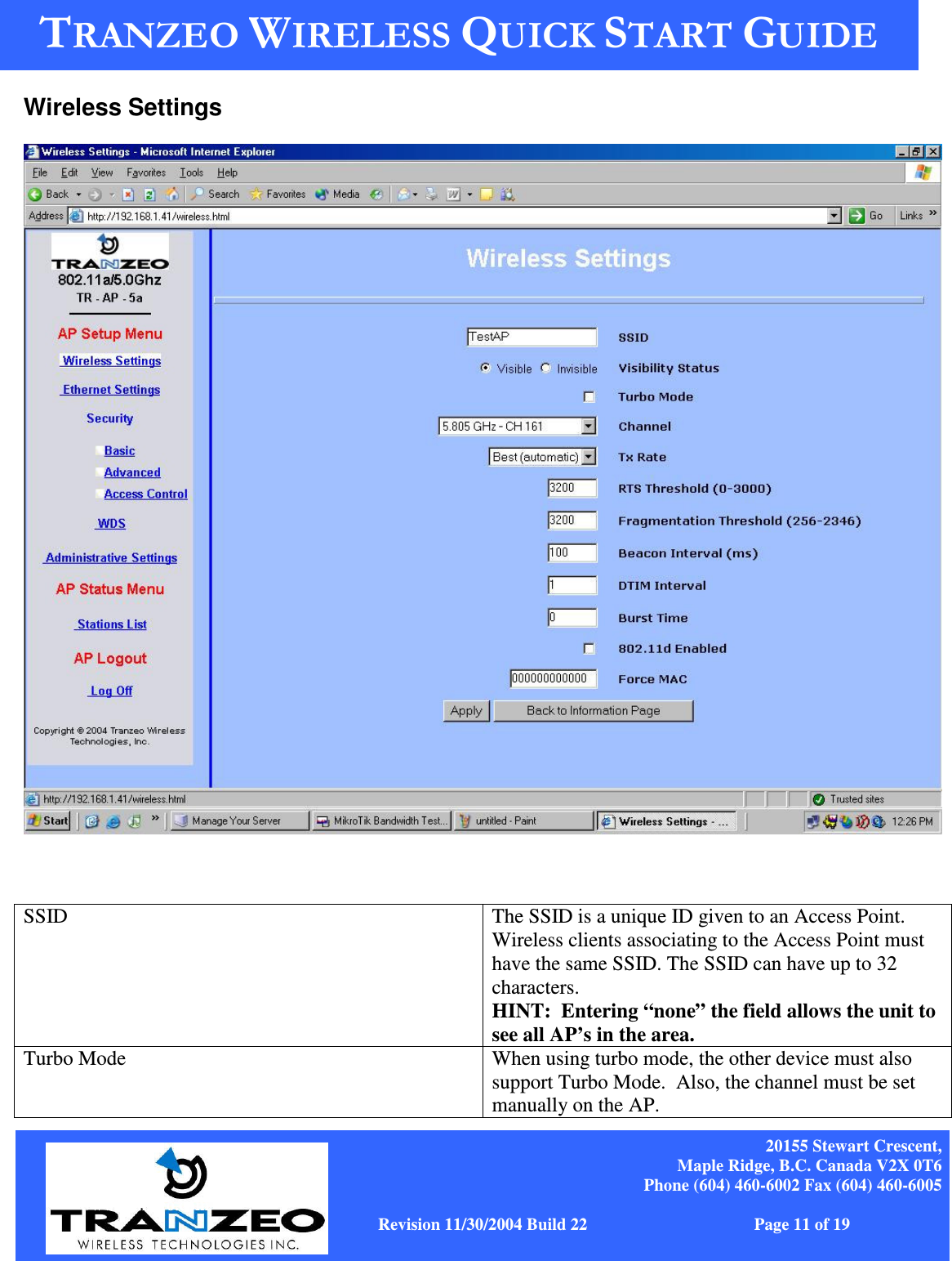
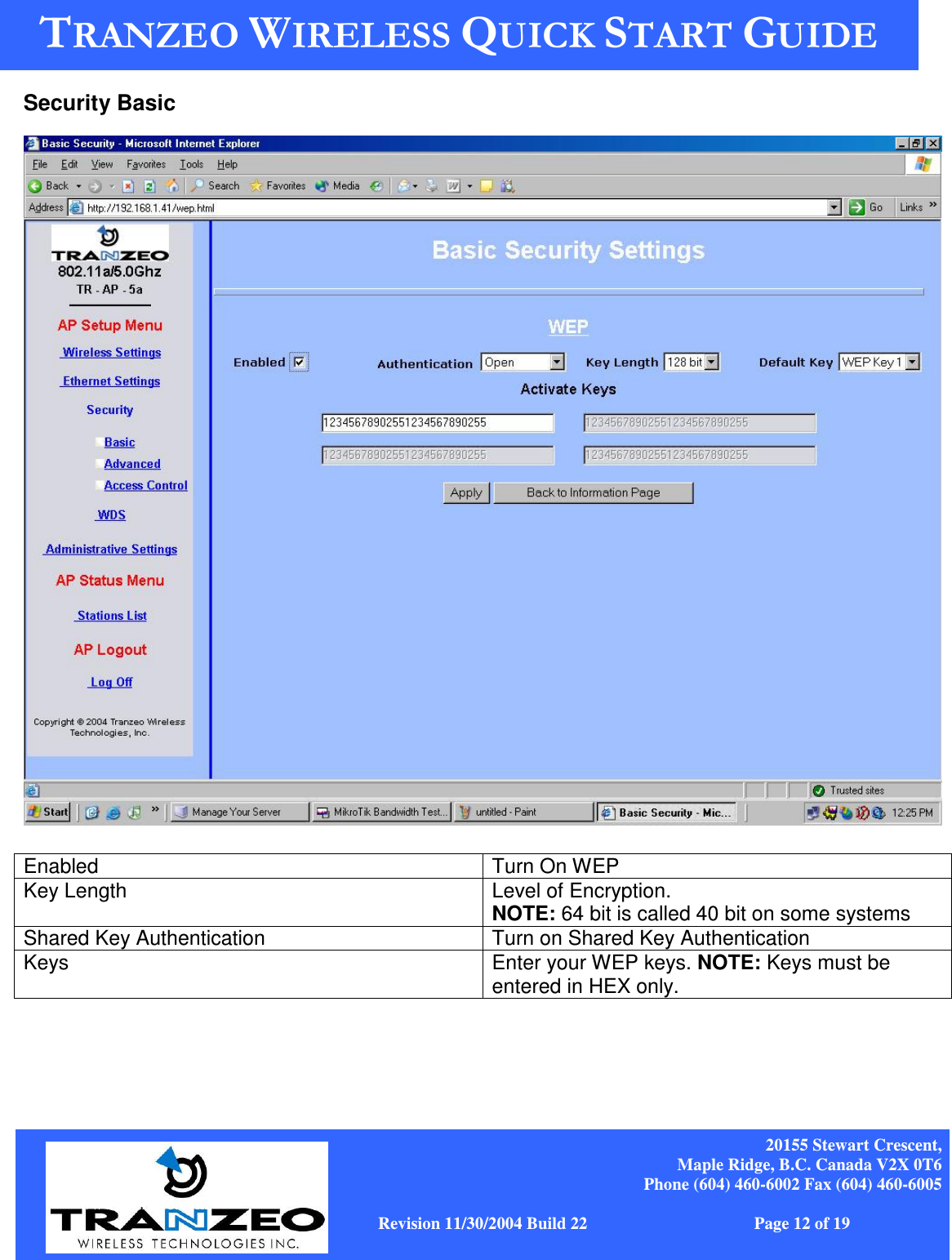
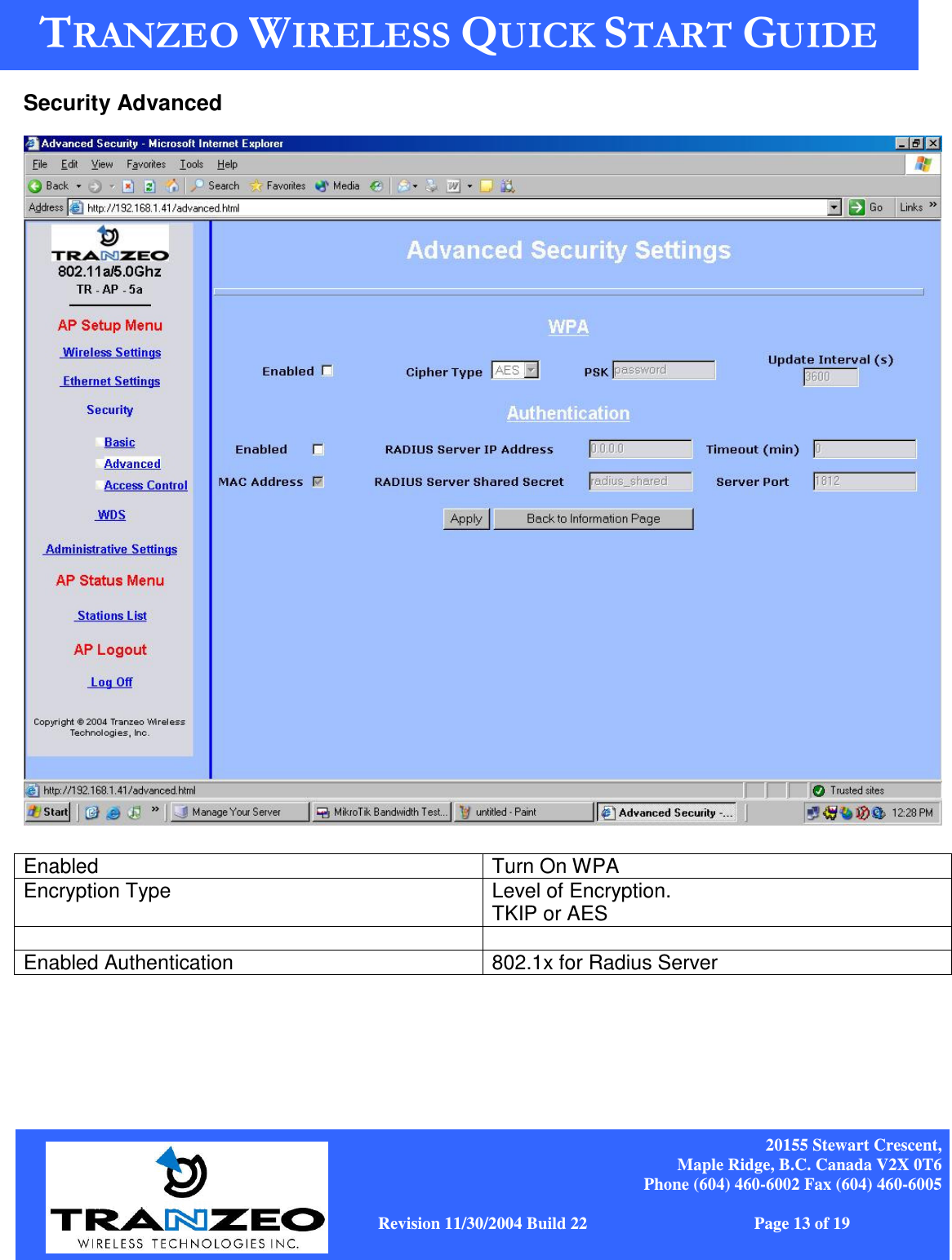
HTML
PDF
Info
Views
User Manual
Discussion / Help
Navigation