Tranzeo Wireless Technologies TR-CPE200 WIRELESS NETWORKING DEVICE User Manual TR CPE200
Tranzeo Wireless Technologies, Inc WIRELESS NETWORKING DEVICE TR CPE200
USERS MANUAL

20155 Stewart Crescent,
Maple Ridge, B.C. Canada V2X 0T6
Phone (604) 460-6002 Fax (604) 460-6005
www.tranzeo.com
Revision 7/26/04 Build 51 Page 1 of 10
TRANZEO WIRELESS QUICK START GUIDE
FCC Information
This equipment has been tested and found to comply with the limits for a Class A digital devices pursuant to
part 15 of the FCC Rules. These limits are designed to provide reasonable protection against harmful
interference when the equipment is operated in a commercial environment.
This equipment generates, uses, and can radiate radio frequency energy and, if not installed and used in
accordance with the instruction manual, may cause harmful interference to radio communication.
Operation of this equipment in residential area is likely to cause harmful interference in which case the user will
be required to correct the interference at this own expense.
The user should not modify or change this equipment without written approval from company name.
Modification could void authority to use this equipment.
For the safety reason, people should not work in a situation which RF Exposure limits be exceeded. To prevent
the situation happening, people who work with the antenna should be aware of the following rules
1. Install the antenna in a location where a distance of 32.5 cm from the antenna may be maintained.
2. While installing the antenna in the location, please do not turn on the power of wireless card.
3. While the device is working, please do not contact the antenna.
4. RF exposure: The antenna used for this transmitter must not be co-located or operating in conjunction with
any other antenna or transmitter”
Copyright
Copyright © 2004 all rights reserved. No part of this publication may be reproduced, adapted, stored in a
retrieval system, translated into any language, or transmitted in any form or by any means without the written
permission of the supplier.
About This Manual
The purpose of this manual is for the setup of the TRANZEO TR-CPE200. This manual, revised as version 1.0.0
in 2004, includes procedures assisting you in avoiding unforeseen problems.

20155 Stewart Crescent,
Maple Ridge, B.C. Canada V2X 0T6
Phone (604) 460-6002 Fax (604) 460-6005
www.tranzeo.com
Revision 7/26/04 Build 51 Page 2 of 10
TRANZEO WIRELESS QUICK START GUIDE
TR-CPE Quick Start Guide
Introduction
This next-generation wireless LAN device – the TRANZEO TR-CPE200, brings Ethernet-like performance to the
wireless realm. Fully compliant with the IEEE802.11b standard, the TRANZEO TR-CPE200 also provides powerful
features such as the Internet-based configuration utility, and WEP security. Maximize network efficiency while
minimizing your network investment and maintenance costs.
TR-CPE Quick Start Guide
Hardware Installation
Product Kit
Before installation, make sure that you have the following items:
The TR CPE200 x 1
DC Power Adapter x 1
Power over Ethernet Adapter x 1
Ethernet Boot x 1
Ethernet Boot Tightening Bracket x 1
Mounting Bracket x 1
Ket Nuts (With Washer Attached) x 8
U-Bolt w/ 2 Nuts x 1
RJ-45 Patch Cable x 1
Spare Ethernet Boot Gasket x 1
If any of the above items is not included or damaged, please contact your local dealer for support.
Mechanical Description
LED panel of the Wireless LAN Smart Access Point:
The following table provides an overview of each LED activity:
LED Definition Activity Description
Label Color Indicators
POWER Amber On: Powered On
Off: No Power
LAN Amber/Green* On: Ethernet Link
Flashing : Ethernet Traffic
Off: No Ethernet Link
Radio Red On: Radio Link
Flashing Radio Activity
Off: No Radio Link
*Only one of the two colors will be shown. Actual color will vary between units.
Power Supply: ONLY use the power adapter supplied with the TR- CPE200. Otherwise, the product may be
damaged.
20155 Stewart Crescent,
Maple Ridge, B.C. Canada V2X 0T6
Phone (604) 460-6002 Fax (604) 460-6005
www.tranzeo.com
Revision 7/26/04 Build 51 Page 3 of 10
TRANZEO WIRELESS QUICK START GUIDE
2-4 Hardware Installations
Take the following steps to set up your TR-CPE200.
Site Selection: Before installation, determine the TR-CPE200 Units location. Proper placement of the unit is
critical to ensure optimum radio range and performance. You should perform a Site Survey to choose a proper
placement for your unit. Place your unit within the line of sight of the Access Point. Obstructions may impede
performance of the unit.
Tools Required to Install
• One 3/8 wrench
• One RJ-45 Crimper
• A suitable length of Cat 5 Cable to bring the signal from the unit to the Power over Ethernet Adaptor
• RJ-45 Jacks
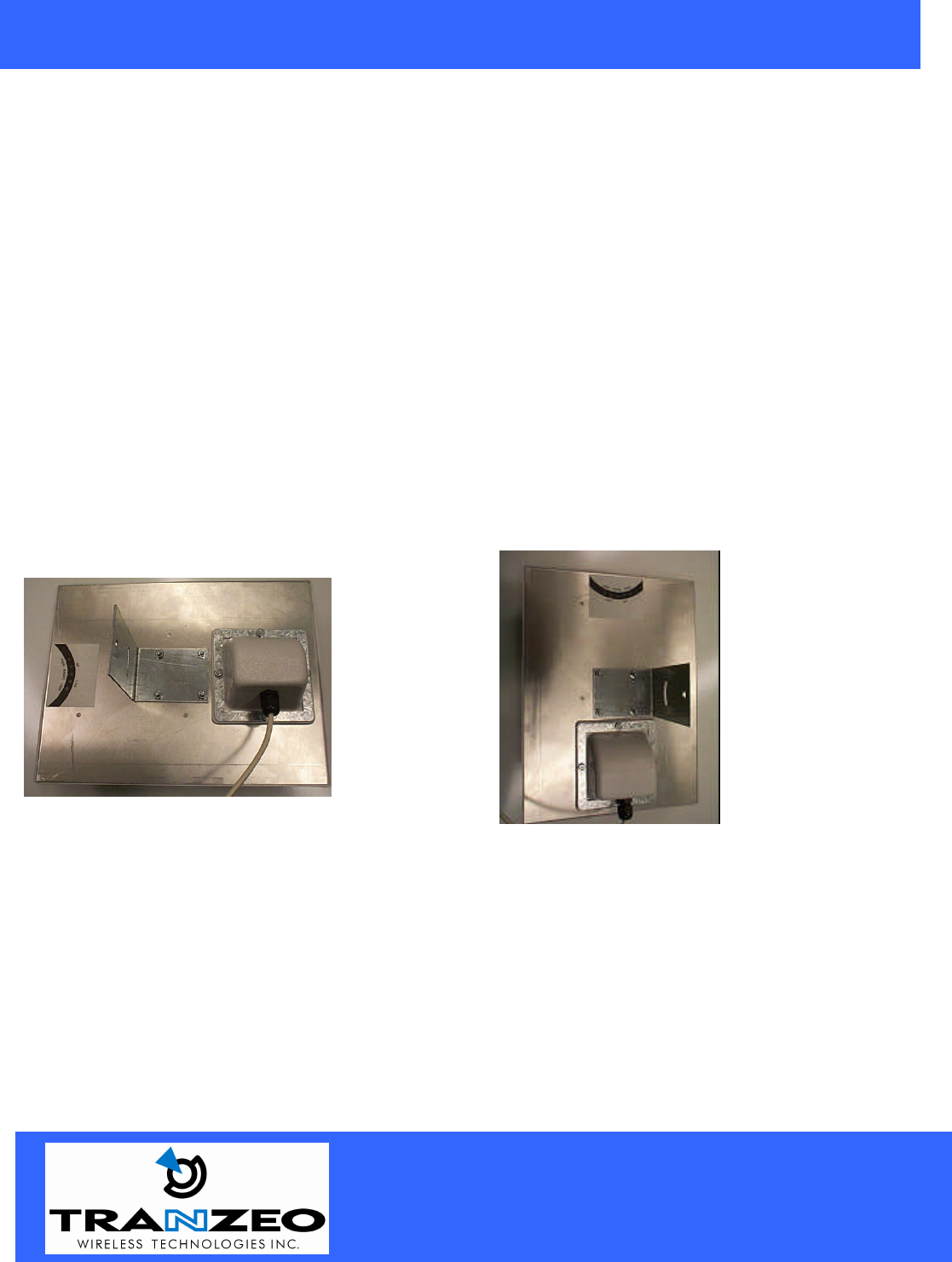
Before installing, you must determine if you will be installing the unit in a horizontal or vertical orientation.
The TR-CPE200 model can be mounted in either orientation. The Ethernet boot should always be placed so
that the cable runs toward the ground for maximum environmental protection.
Vertical Orientation Horizontal Orientation
20155 Stewart Crescent,
Maple Ridge, B.C. Canada V2X 0T6
Phone (604) 460-6002 Fax (604) 460-6005
www.tranzeo.com
Revision 7/26/04 Build 51 Page 4 of 10
TRANZEO WIRELESS QUICK START GUIDE
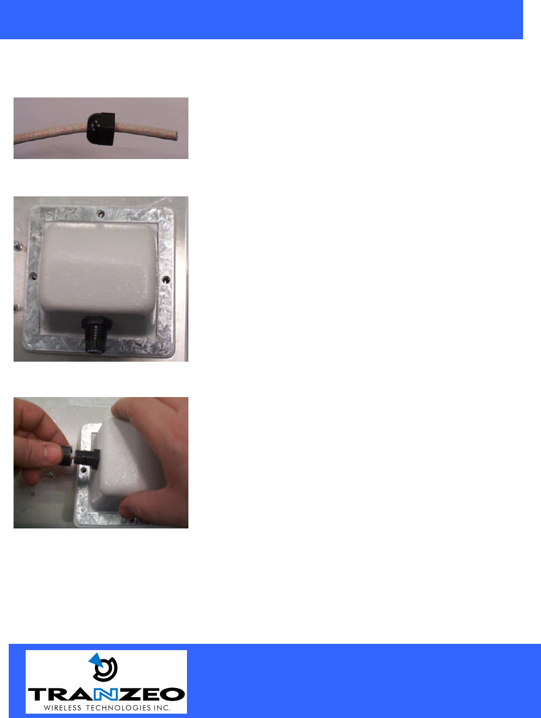
Connecting the Ethernet Cable
Step 1
Place the Ethernet Boot Cover over the end of your Cat 5 Cable.
Step 2
Step 3
Insert the Cat 5 Cable and tighten the Boot Cover. Be sure to pull
enough cable through to reach the RJ-45 connector with an RJ-45 jack
attached.
Hand tighten only. DO NOT OVERTIGHTEN as you may damage the
environment seal.
A
ttach tightening bracket on
top of the Ethernet Boot. This
is easiest to do before you attach the CAT 5 cable. The
Gasket must be attached to the Boot so that it sits between
the radio and the boot.
20155 Stewart Crescent,
Maple Ridge, B.C. Canada V2X 0T6
Phone (604) 460-6002 Fax (604) 460-6005
www.tranzeo.com
Revision 7/26/04 Build 51 Page 5 of 10
TRANZEO WIRELESS QUICK START GUIDE
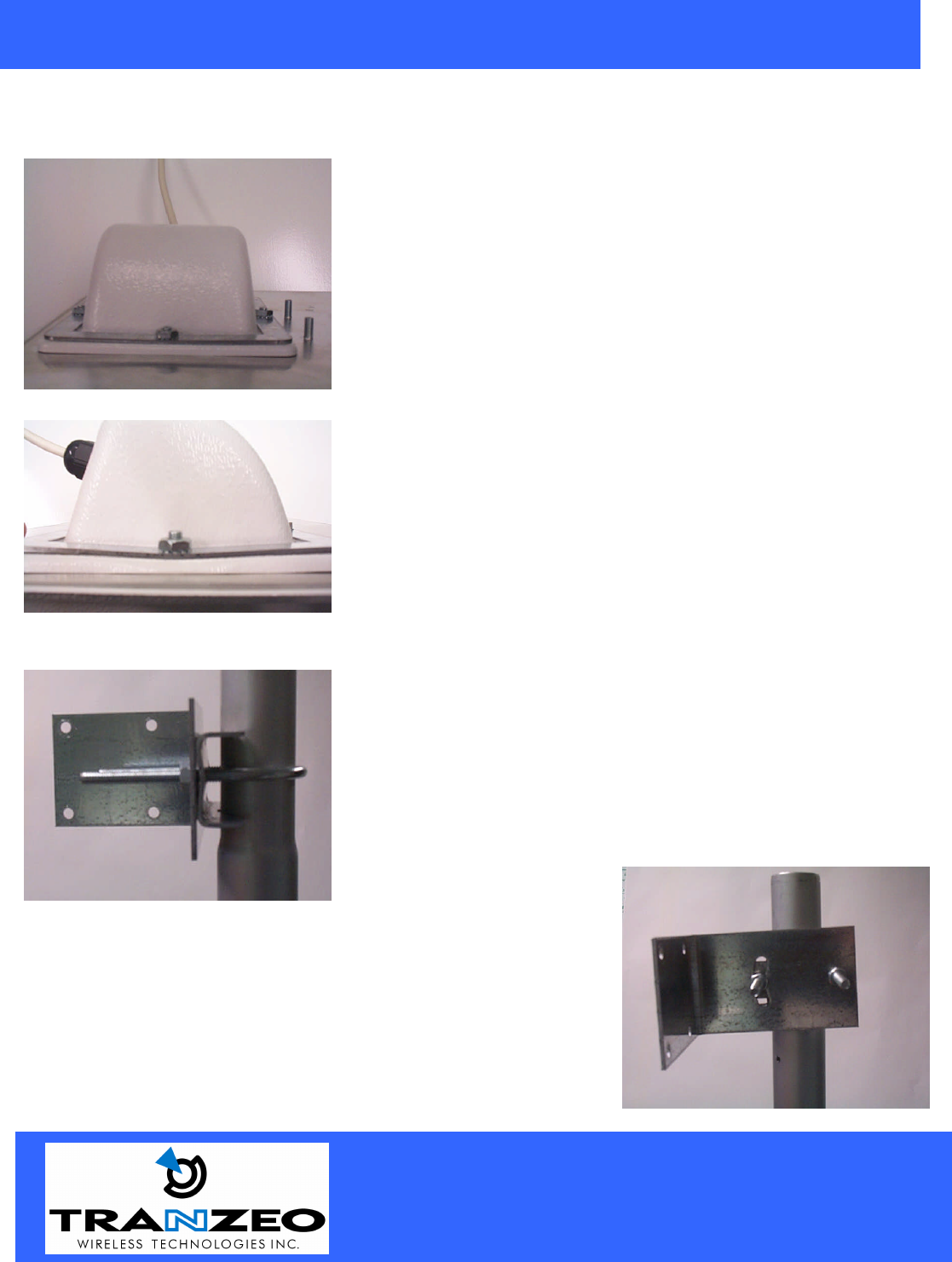
Step 4
Place the Ethernet boot over the 4 Screw Posts. The screws should just
barely clear the tightening bracket. Apply 4 Ket nuts to the screw posts
and tighten until the metal plate makes full contact with the Ethernet
boot. Do not over tighten.
This is an example of over tightening. Over tightening connections like
this may crack the boot and will compromise the gasket seal. Over
tightening is not covered by warranty.
Attaching the Mounting Bracket
As shown below, the U-Bolt is designed to mount around a pole.
Tighten bolts sufficiently to prevent any movement.
Down or up tilt can be adjusted by swinging the unit before tightening
the U-Bolt.
20155 Stewart Crescent,
Maple Ridge, B.C. Canada V2X 0T6
Phone (604) 460-6002 Fax (604) 460-6005
www.tranzeo.com
Revision 7/26/04 Build 51 Page 6 of 10
TRANZEO WIRELESS QUICK START GUIDE
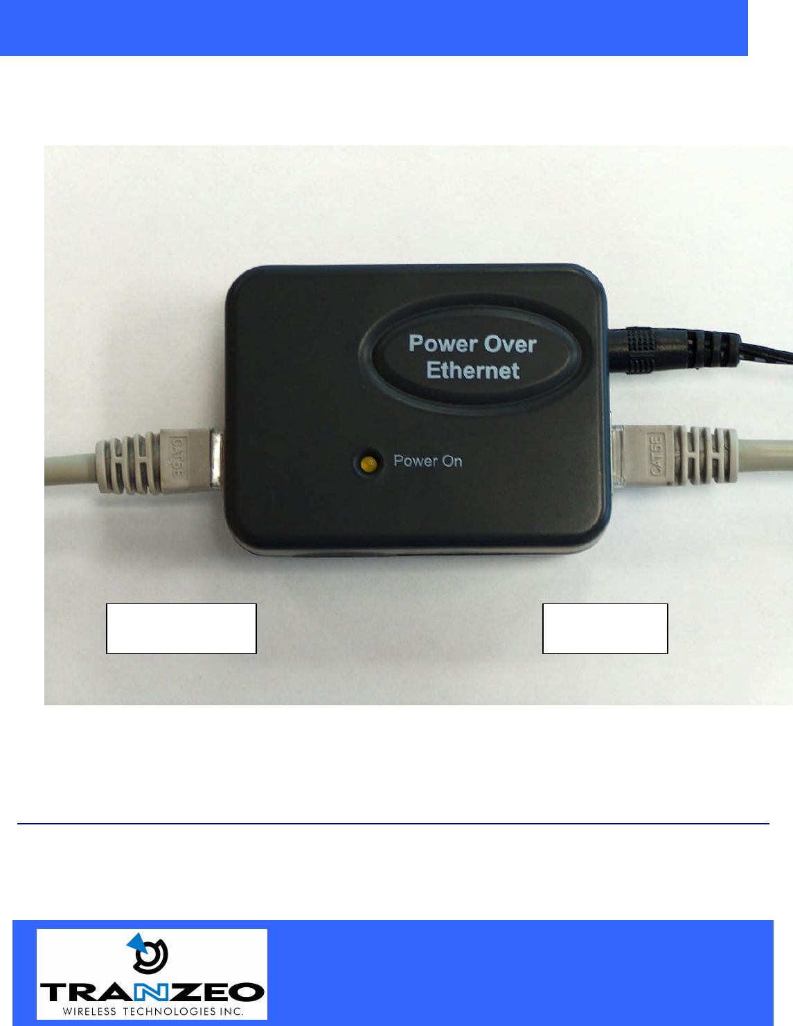
Connect the Power Cable
Connect the power adapter to the power socket on the Power over Ethernet Adaptor, and plug the other end
of the power into an electrical outlet. Plug the RJ-45 Cable from the unit into the POE. The Station Adaptor
will be powered on and the Red power indicator on the top panel will turn on.
NOTE: ONLY use the power adapter supplied with the Access Point. Otherwise, the product may be
damaged.
To
PC
To CPE
20155 Stewart Crescent,
Maple Ridge, B.C. Canada V2X 0T6
Phone (604) 460-6002 Fax (604) 460-6005
www.tranzeo.com
Revision 7/26/04 Build 51 Page 7 of 10
TRANZEO WIRELESS QUICK START GUIDE
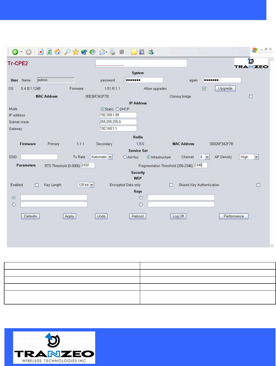
HTML Interface2
NOTE: The default IP address is 192.168.1.99
System Settings
Password Allows user to change passwords.
Again Confirm Password
Firmware Lists Diagnostic Information about internal firmware
Allow Upgrades Allows User to Change Firmware Version
Cloning Bridge If selected, the CPE will use the MAC address of the
device it is attached to
20155 Stewart Crescent,
Maple Ridge, B.C. Canada V2X 0T6
Phone (604) 460-6002 Fax (604) 460-6005
www.tranzeo.com
Revision 7/26/04 Build 51 Page 8 of 10
TRANZEO WIRELESS QUICK START GUIDE
IP Address
Mode Select Static to enter a valid Static IP or select DHCP
address for auto select.
IP Address This field is Read Only if DHCP is selected
Subnet Mask This field is Read Only if DHCP is selected
Gateway This field is Read Only if DHCP is selected
Radio
Firmware Lists Diagnostic Information about internal firmware
MAC Address Radio MAC Address
Service Set
SSID The SSID is a unique ID given to an Access Point.
Wireless clients associating to the Access Point must
have the same SSID. The SSID can have up to 32
characters.
TX Rate The rate at which the radio will communicate with the
AP. NOTE: Setting this rate below the maximum
possible does not limit bandwidth, and often has a
negative impact on the operation of your network.
Ad – Hoc / Infrastructure Select Infrastructure for any WISP operation
Channel Only applicable in Ad-Hoc Mode
AP Density Best set to Low in most WISP applications
RTS Threshold (0-3000) Select RTS that works best in your location. A
general rule of thumb is the more clients you have, the
lower the value should be set.
Fragmentation Threshold (256-2346) Select Fragmentation that works best in your location.
The lower the Fragmentation, the smaller the packets.
Security
Enabled Turn On WEP
Key Length Level of Encryption.
NOTE: 64 bit is called 40 bit on some systems
Encrypted Data only Only Connect to a system if WEP is enabled
Shared Key Authentication Turn on Shared Key Authentication
Keys Enter your WEP keys. NOTE: Keys must be
entered in HEX only.
20155 Stewart Crescent,
Maple Ridge, B.C. Canada V2X 0T6
Phone (604) 460-6002 Fax (604) 460-6005
www.tranzeo.com
Revision 7/26/04 Build 51 Page 9 of 10
TRANZEO WIRELESS QUICK START GUIDE
Buttons
Default – Resets the Radio to factory Defaults
Apply - Save Changes and reset Radio
Undo - Clear any changes not applied
Reboot - Reboot the radio
Performance - Loads the test page
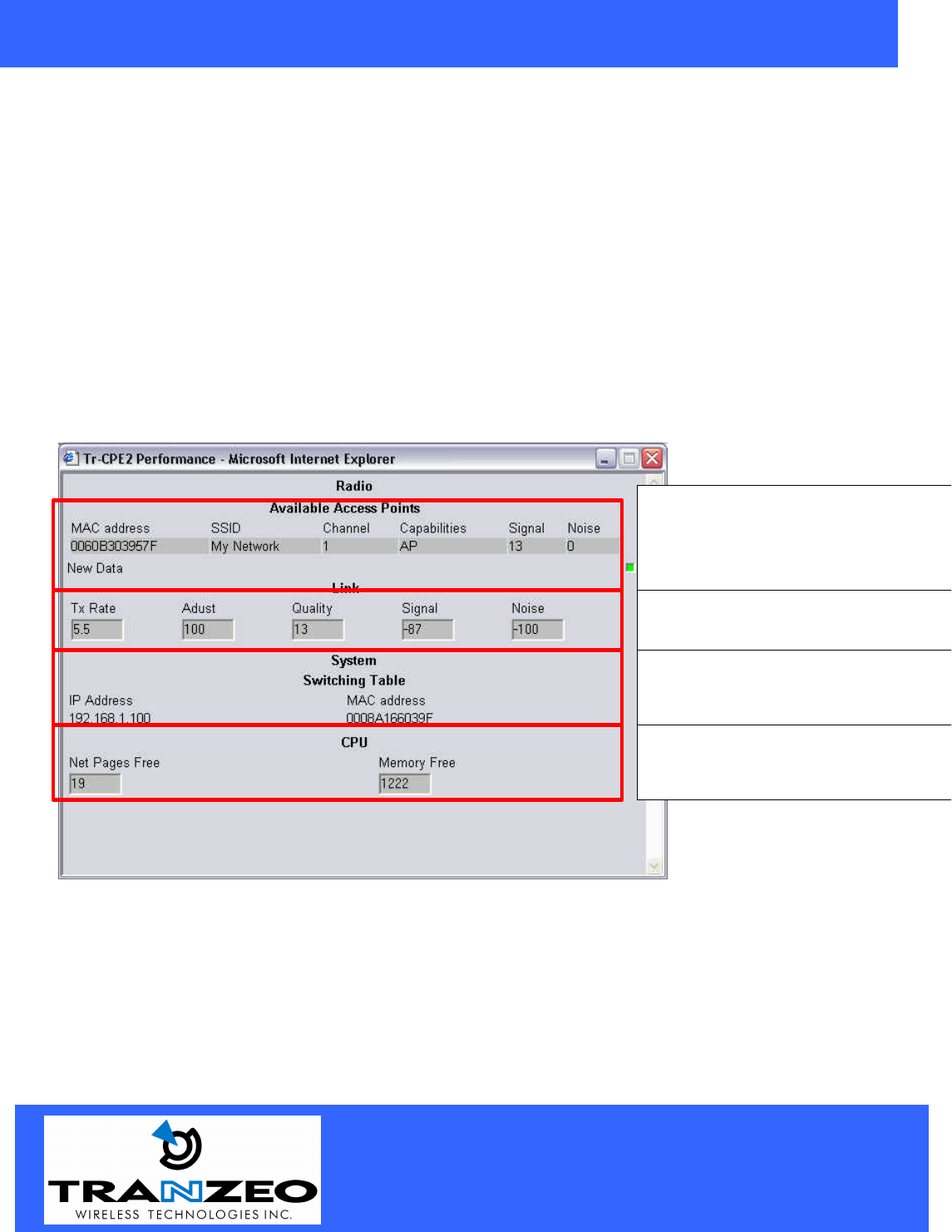
Performance
Shows all available Access Points using the
SSID in this radio.
Hint: Leave the SSID field blank
to see all
APs in the area.
Shows your current TX rate and the quality
of the link. The signal level is in dbm.
Shows all MACS currently being bridged by
the Radio with their IP’s and Mac Address
Diagnostic Info about the Radio for
Technical Support issues.
20155 Stewart Crescent,
Maple Ridge, B.C. Canada V2X 0T6
Phone (604) 460-6002 Fax (604) 460-6005
www.tranzeo.com
Revision 7/26/04 Build 51 Page 10 of 10
TRANZEO WIRELESS QUICK START GUIDE
RF Exposure Evaluation
FCC 1.1310 states that the criteria listed in the following table shall be used to evaluate the
environmental impact of human exposure to RF radiation as specified in 1.1307(b)
Frequency Range
(MHZ) Electric Field
Strength (V/m) Magnetic Field
Strength (A/M) Power Density
(mW/cm2) Average Time
(A) Limits for Occupational/Control Exposures
300-1500 -- -- F/300 6
1500-100,000 -- -- 5 6
(B) Limits for General Population/Uncontrolled Exposures
300-1500 -- -- F/1500 6
1500-100,000 -- -- 1 30
Fries Formula
Fries transmission formula: Pd = (Pout*G)/(4* p*r2) Where
Pd = power density in mW/cm2
Pout = output power to antenna in mW.
G = gain of antenna in the direction of interest relative to an isotropic radiator.
R = the distance between the observation point and the center of the radiator in cm.
Pd is the limit of MPE, 1mW/cm2.
If we know the maximum gain of the antenna and the total power input to the antenna we can calculate the
distance r where the MPE limit is reached.
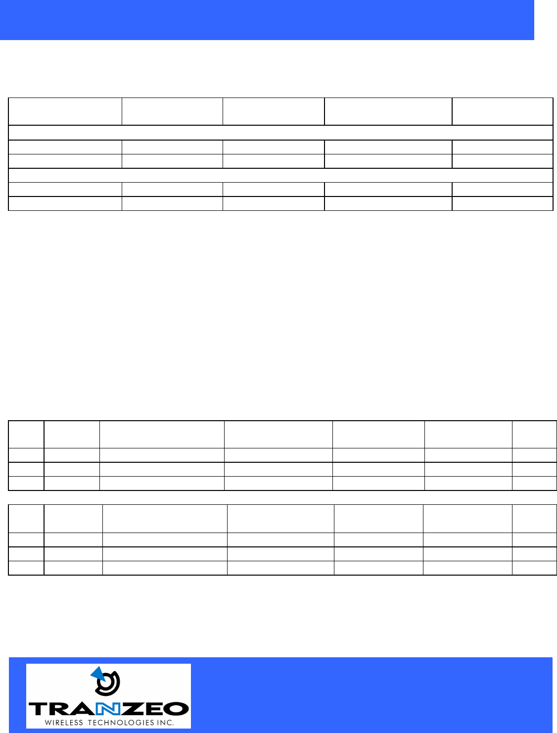
RF exposure evaluation distance calculation
TR-CPE200-19
Chan
Freq
(MHz) Output Power to
Antenna (dBm) Output Power to
Antenna (mW) Max Antenna
Gain (dBi) Numeric
Antenna Gain R(cm)
1 2412 21.06 128 19.5 89.1 30.1
6 2437 21.34 136 19.5 89.1 31.1
11 2462 21.74 149 19.5 89.1 32.5
TR-CPE200-15
Chan
Freq
(MHz) Output Power to
Antenna (dBm) Output Power to
Antenna (mW) Max Antenna
Gain (dBi) Numeric
Antenna Gain R(cm)
1 2412 21.06 128 15.5 35.5 19.0
6 2437 21.34 136 15.5 35.5 19.6
11 2462 21.74 149 15.5 35.5 20.5
As shown above, the minimum distance where the MPE limit is reached is 32.5 cm for the TR-CPE200
product family.