Tranzeo Wireless Technologies TRZMX57 802.11n/a Long-Range outdoor AP/CPE User Manual

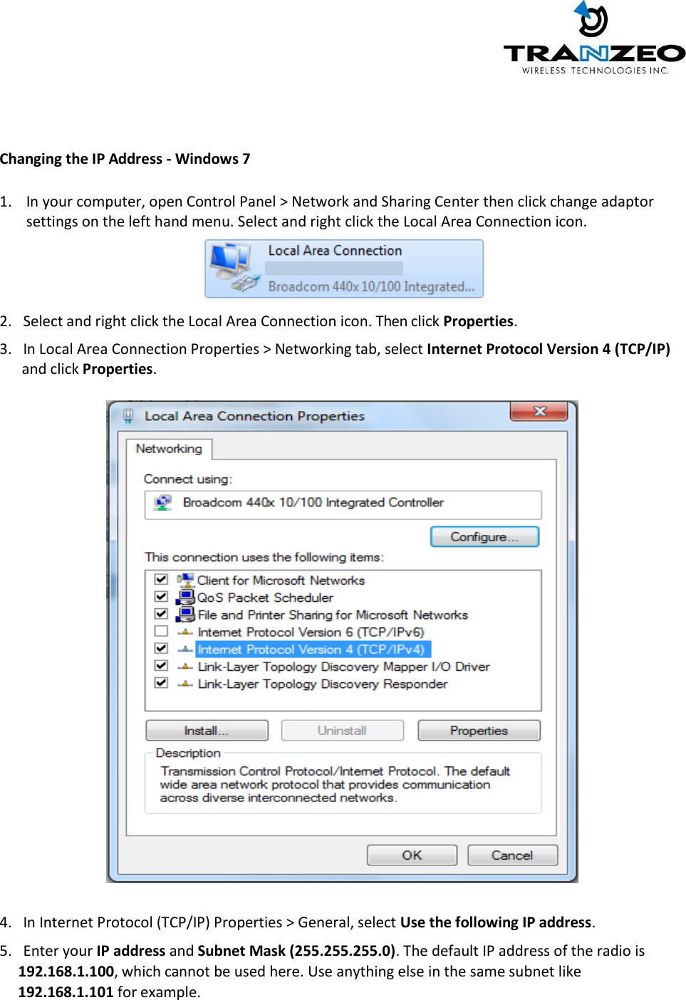
Tranzeo Wireless Technologies, Inc 802.11n/a Long-Range outdoor AP/CPE Users Manual

Contents

Users Manual

TRANZEO TR-MX50-15 23MX50-15-N 22N2@nMX                                   Tranzeo TR-MX5 Quick Start Guide          Revision 1.1 Firmware TR-MX-0.1.7 Date 2014-12-29
 TR-MX5 2    Tranzeo Wireless Technologies Inc. 19473  Fraser  Way Pitt  Meadows,  BC Canada V3Y 2V4    Contact Information  Toll Free Number 1.866.872.6936 General Inquiries Technical Support 1.888.460.6366 Sales Local Number 1.604.460.6002 Technical Support Fax Number 1.604.460.6005                            Training    Website   Additional product Information and support details are available on our web site:                              http://www.tranzeo.com             About Tranzeo Wireless Technologies Inc TM  Tranzeo  Wireless  Technologies  Inc.  leads  the  wireless  broadband  industry  for  value,  by producing  high-performance  wireless  network  equipment  with  a  low  cost  of  ownership  and unparalleled service allowing communities and businesses to communicate without boundaries. Since the company's inception in 2000, Tranzeo's optimum cost effectiveness, premium quality and  responsive support  have attracted  a  growing  number of devoted dealers and  distributors worldwide.
 TR-MX5 3  Copyright    This document contains information, which is protected by copyright. Reproduction, adaptation, or translation without prior permission is prohibited, except as allowed under the copyright laws.  © Copyright 2014 Tranzeo Wireless Technologies Inc.      All Rights Reserved.  Feedback Please direct any comments or suggestions about this document to: sales@tranzeo.com   Trademark Information Tranzeo® is a registered trademark of Tranzeo Wireless Technologies Inc.    Disclaimer Tranzeo Wireless Technologies Inc provides this manual without warranty of any kind, expressed or implied, including but  not limited to the implied warranties of merchantability and fitness for a particular purpose.  Tranzeo Wireless Technologies Inc may make improvements and/or changes to the product and/or specifications of the product described in this manual, without prior notice. Tranzeo Wireless Technologies Inc will not be liable for any technical  inaccuracies or typographical errors found in this guide. Changes are periodically made to the information contained herein and will be incorporated into later versions of the manual. The information contained is subject to change without prior notice.
 TR-MX5 4  Safety Information     FCC Compliance  This device has been tested and found to comply with the limits for a Class B digital device pursuant to Part 15 of the FCC rules. These limits are designed to provide reasonable protection against harmful interference when the device is operated in a residential environment. This device generates, uses, and can radiate radio frequency energy. If not installed and used in accordance with the user guide, may cause harmful interference to radio communication. In case of harmful interference, the users will be required to correct the interference at their own expense.  The users should not modify or change this device without written approval from Tranzeo Wireless Technologies.  Modification will void warranty and authority to use the device.  For safety reasons, people should not work in a situation where RF exposure limits could be exceeded. To prevent this situation, the users should consider the following rules:    Install the antenna so that there is a minimum of 100cm (39.37”) of distance between the antenna and people.  Do not turn on power to the device while installing the antenna.  Do not connect the antenna while the device is in operation.  Do not collocate or operate the antenna used with the device in conjunction with any other antenna or transmitter.     Professional Installation Required   The product requires professional installation. Professional installers ensure that the equipment is installed following local regulations and safety codes.  Within the 5.15–5.25 GHz band, UNII devices are restricted to indoor operations only to reduce any potential for harmful interference to co-channel MSS operations and prohibited from being operated on this band outdoors. This device has been designed to operate with the antennas listed below and having a maximum gain of 11 dBi.  Antennas not included in this list or having a gain greater than 11 dBi are strictly prohibited for use with this device. The required antenna impedance is 50 ohms.    MME5-11: 5GHz 11dBi 2x2 directional panel antenna       Industry Canada Compliance   Operation of this device is subject to the following two conditions: (1) this device may not cause  interference,  and  (2)  this  device  must  accept  any  interference,  including interference that may cause undesired operation of the device.
 TR-MX5 5   Table of Contents TR-MX5 OVERVIEW .............................................................................................................................................................. 6 Introduction ......................................................................................................................................................................... 6 Applications ......................................................................................................................................................................... 7 Key Features ........................................................................................................................................................................ 7 Product Description .......................................................................................................................................................... 8 TR-MX5 Mounting ............................................................................................................................................................. 9 OPERATING MODES ........................................................................................................................................................... 11 Access Point and Access Point WDS Mode ........................................................................................................... 11 Access Point WDS Mode .............................................................................................................................................. 11 Client Mode ....................................................................................................................................................................... 12 Client WDS Mode ............................................................................................................................................................ 12 Router Mode ..................................................................................................................................................................... 13 TR-MX5 QUICK INSTALL GUIDE ................................................................................................................................... 15 Installing the Ethernet Cable into the TR-MX5 ................................................................................................... 15 TR-MX5 CONFIGURATION ............................................................................................................................................... 19 MAIN MENU ...................................................................................................................................................................... 19 Save Changes ............................................................................................................................................................... 19 STATUS ............................................................................................................................................................................... 20 WIRELESS SETTINGS .................................................................................................................................................... 22 WIRELESS MODES ..................................................................................................................................................... 23 NETWORK .............................................................................................................................................................................. 27 LAN SETTINGS ............................................................................................................................................................ 27 SYSTEM .................................................................................................................................................................................... 28 FIRMWARE UPGRADES ............................................................................................................................................... 28 LED INTERPRETATION ................................................................................................................................................ 30 LED CONFIGURATION .................................................................................................................................................. 31 WARRANTY ........................................................................................................................................................................... 32 Limited Warranty ........................................................................................................................................................... 32 Warranty Conditions ..................................................................................................................................................... 32
 TR-MX5 6   TR-MX5 OVERVIEW Introduction TR-MX5 is an all-in-One AP/WDS/CPE device. Tranzeo’s TR-MX5 series of wireless LAN products are IEEE 802.11a/n compliant, operate in the license-free 5 GHz frequency band, and support data rates of up to 300 Mbps. The versatile multi-mode design supports AP and CPE modes, as-well-as WDS and Bridge modes. It also features advanced networking and management capabilities including WEP/WPA/WPA2 security, WMM QoS, and NAT Routing.   The TR-MX5 offers new options such as up to 4 Virtual Access Points, VLANS, choice of 20/40 MHz channels and Layer 2 transparent Bridging.  The compact TR-MX5 design features a high performance radio. The all-in-one design comes complete with a passive PoE injector and DC adaptor, requiring a single CAT5 cable for power and data, yielding the lowest cost of ownership.  The TR-MX5 also features a weather-resistant enclosure that is compliant with the IP55 environmental standards, requiring minimal installation and maintenance costs in conditions ranging from -40° C to +60° C. The TR-MX5 family of products is also backed by a 1-Year Parts and Labor Warranty and Tranzeo’s unparalleled Lifetime Technical Support for worry-free network operation.  It is PoE powered, which allows the radio to be used in areas where power outlets are not readily available.  It also simplifies the installation by requiring a single Cat5e cable for supplying power and carrying data.  The access point also incorporates a unique set of advanced features such as: up to 4 Virtual AP’s to deliver multiple services; long-range parameter fine-tuning which provide the access point with the ability to auto-calculate parameters such as slot time, ACK time-out and CTS time-out to maximize range.
 TR-MX5 7  Applications  Example applications for TR-MX5   Remote Data Acquisition Internet Service (WISP) Video Transmission Security and Surveillance Private Networks Wi-Fi Hotspots Building to Building (P2P)  Marinas / RV /Parks Hotels  WISP network   Key Features These are the main features of the TR-MX5:  IEEE 802.11a/n Compliant  Operates in 5.2 & 5.8 GHz band  Integrated 11dBm Antenna  2 x 2 MIMO support  Dual Ethernet ports  AP/CPE/WDS/Bridge/Router Modes  Up to 300 Mbps Data Rate  Adjustable Output  20/40  MHz Channels  Antenna Alignment LED’s  WEP/WPA/WPA2 Security and WMM QoS  NAT Routing, VPN Pass-Through  Traffic Shaping  Power-over-Ethernet (PoE)  HTTP/HTTPS Web Based Management Tools
 TR-MX5 8                                Product Description       ① PoE LAN  ② PoE WAN (in Router mode)  PoE LAN (in Bridge Mode)  ③ Reset   ③     ① ②   Wall Mount Hole        Pole Mount Holders  L-Mount (Option)
                         4                     TR-MX5 Mounting  ◆ H o w to open the sliding door           Unlatch the weatherproof sliding door from the rear of the base to open. Slide the weatherproof sliding door downwards by griping onto the indented surface of the weatherproof sliding door and the rear.  ◆ H o w to close the sliding door            Align the base with the  weatherproof sliding door. Slide the weatherproof sliding door upwards until it clicks into place.   ◆ H o w to tie the strap on the pole
                ◆  Mounting and Radio forward Diagram  Standard Pole Mount                        *Option Adjust Antenna L- Mount                      *Option Wall
  OPERATING MODES Access Point and Access Point WDS Mode The Access Point Mode is the default mode of the device. It enables the bridging of wireless clients to wired network infrastructure and enables transparent access and communication with each other. The  illustration  below  shows  a  typical  resources  sharing  application  example  using  this  device.  The wireless users are able  to access the file  server connected to the switch, through the access point in Access Point Mode.     Access Point WDS Mode This is mode is generally use for point-to-point or point-to-multi-point connection. It is mainly use with Client WDS to build the point and multi-point connections.
  Client Mode In Client mode the device acts as a wireless client. When connected to an access point, it creates a network link between the Ethernet network connected at this client device, and the wireless Ethernet network connected at the access point.  In this example the workgroup PCs on the Ethernet network connected to the Client device can access the printer across the wireless connection to the access point where the printer is connected.    Client WDS Mode  Client WDS mode is similar to Station mode. The difference is Client WDS must connect to access point configured to Access Point WDS (or RootAP) mode. Client  WDS  is  mainly  use  for  point-to–point  connection  between  2  buildings  or  locations  as  far  as several kilometer away.  Point-to-Point Point-to-MultiPoint An access point setup as Access Point WDS (or RootAP) and other as Client WDS (Transparent Client). An access point setup as Access Point WDS (or RootAP) and several other devices as Client WDS (or Transparent Client).
  This mode is generally used for outdoor connections over long distances, or for indoor connections between local networks.  Router Mode In Router Mode, the device also operates as a router.  Either the wireless or Ethernet can be setup as WAN connection to a broadband modem. Wireless as WAN  is  known  as  Client +  Router  mode  (or  Wireless  Routing  Client  mode)  and  Ethernet  as  WAN  is known  as  AP  +  Router  mode  (or  Gateway  mode).  Device  supports  both  types  of  broadband connections Static IP and dynamic IP. For setup details refer to the respective section.  The illustration below shows the Ethernet port is setup as the WAN port and the wireless connection as the LAN.  Client + Router connection example Wireless is use to connect to the broadband. Ethernet is the local network (LAN) sharing the broadband connection.
    AP + Router connection example Ethernet is use to connect to the broadband. Wireless is the local network (LAN) sharing the broadband connection.     Broadband Internet Access Type: Static IP Address Use Static IP Address you have subscribed a fixed IP or range IP addresses from your ISP.  Dynamic IP Address With Dynamic IP Address the device automatically request IP address from modem or ISP.
    TR-MX5 QUICK INSTALL GUIDE  Installing the Ethernet Cable into the TR-MX5 Install using straight through Ethernet cables Summary Steps 1. Remove Bottom Cover as described above 2. Connect a PC/laptop to Ethernet/LAN port of the POE 3. Connect an Ethernet cable from the powered RJ45 POE port to TR-MX5 4. Power the POE unit with the supplied power adaptor (connect only to a grounded outlet) 5. Configure PC with a static IP address in the same subnet of the TR-MX5  (192.168.1.x) like 192.168.1.101 6. From a web browser, connect to the configuration page http://192.168.1.100 (username/password as below)     Step 1:  Hold unit with release tabs facing up and the cover away from you. Push down release tab at one end and pull away that corner with the other hand, just over the catch clip, leaving about a 2mm gap. Do the same on the other end and the cover can be pulled off easily to reveal the dual Ethernet ports and Reset pin. Ensure that the black cable inserts remain in place and do not fall out. Mount the TR-MX5 on a suitable pole with the supplied straps as shown  .
    Step 2: Connect an Ethernet cable form the PC/Laptop to the PC connector on the POE LAN port.   Step 3: Connect an Ethernet cable from the TR-MX5 unit to the POE port on the POE.  Note: On the TR-MX5, there are two Ethernet ports. It is highly recommended to use the Ethernet port closest to the reset pin as the primary use port. This is the active port used to load new firmware from power on state in the event a firmware recovery procedure is necessary. The other port would be recommended port for daisy chaining  Step 4:            Connect a PC to the “LAN” Port of the POE, with a straight through Ethernet cable. Note:  Connect the radio to the “POE” port and the “LAN” port to PC/switch/router.  Power the POE unit with the supplied cord, and ensure power source has earth pin.    Step 5 Connecting to the TR-MX5 AP Before accessing the configuration interface, you have to change the network connection settings in your computer to be on the same subnet as the radio. Alternatively, you could use the Victor Utility program to assign the radio a temporary IP alias that is on the same subnet as your computer.
     Changing the IP Address - Windows 7  1. In your computer, open Control Panel > Network and Sharing Center then click change adaptor settings on the left hand menu. Select and right click the Local Area Connection icon.    2.   Select and right click the Local Area Connection icon. Then click Properties.  3.   In Local Area Connection Properties > Networking tab, select Internet Protocol Version 4 (TCP/IP)       and click Properties.     4.   In Internet Protocol (TCP/IP) Properties > General, select Use the following IP address.  5.   Enter your IP address and Subnet Mask (255.255.255.0). The default IP address of the radio is       192.168.1.100, which cannot be used here. Use anything else in the same subnet like       192.168.1.101 for example.
    6.  Click OK and Close  Step 6 Web Configuration Page Access   Configuration of TR-MX5 features and options are accessible via the web page. 1. Open your Internet browser (such as Internet Explorer, Chrome, or Firefox). 2. In the address bar, type your IP address (default IP: http://192.168.1.100). 3. In the login dialog, enter your Username and Password. 4. Click OK. You will then access the configuration interface.                           Setup and Configuration via Web GUI  Default IP Address 192.168.1.100 Default Username admin Default Password default
  TR-MX5 CONFIGURATION    Full comprehensive features are covered in the TR-MX5 User guide. These configurations pages serve as a quick start setup guide. MAIN MENU  The top level main menu allows access to the Wireless, Network and System detail configuration options.      STATUS: Current device status and statistical information.             WIRELESS: Basic wireless network interface settings including operating mode, and security options.              NETWORK: Basic network interface including IP mode, IP settings, and DHCP server settings. SYSTEM: System maintenance services including administrator account management, firmware upgrades, and backup/ restore system configuration.    Save Changes You  need  to  apply  changes  to  each page  before  navigating  to  another page; otherwise  changes on  the  last  page  will  be  lost.   When  all  the  changes have been made and applied, then press Save to permanently save changes to flash, or click Discard to discard all changes.
       TR-MX5 20  STATUS  After successfully logging into the TR-MX5, the STATUS page will then be displayed.   You could also navigate back to the STATUS page by clicking STATUS  on the  menu bar.   The STATUS page  displays a  summary  of  the  basic  device configuration,  network  settings, current  link  status,  and  traffic statistics for all interfaces.   WIRELESS  Device: Wireless LAN name Mode:  Displays the current operating mode of the device. SSID: Displays the current SSID (Service Set Identifier) of device when operating in  access point mode.
       TR-MX5 21  Channel: Displays selected channel   and operating frequency running in device. MAC-Address: Displays the MAC address or BSSID of the current active WLAN card running in device. Noise:  Displays Noise Level in dBm Encryption: Display the current active security mode. WEP/WPA/WPA2  Link Status: Displays number of active clients   NETWORK  Device: Ethernet LAN Name Type: Displays the mode used, either static or DHCP client. Address: Displays the current IP address of the LAN (Ethernet) interface. Netmask: Displays the Netmask of the gateway used in LAN. Gateway: Displays the IP address of the gateway used in LAN. DNS 1: Displays the Primary DNS IP address of the LAN setting. DNS 2: Displays the Secondary DNS IP address of the LAN setting. Connected: Displays time duration LAN has been connected. SYSTEM      Uptime : Displays device up time since boot up. The time is expressed in days, hours, minutes and seconds.    Host Name:  Displays the assigned device host name (ID).    System Time: Display device current date and time. Accurate system date and time is  retrieved  from  the  i n t e r n e t   services  using  NTP  (Network  Time Protocol) if device is setup and connected to internet. Otherwise, the date  and  time  update  from device  own autonomous clock.   NTP  will be far more accurate.   Firmware Version:           Displays current firmware version in operation.    Boot Loader: Displays current boot loader version of the device.
       TR-MX5 22   WIRELESS SETTINGS This page displays the wireless configuration of the device. The contents are slightly different for access point and client modes. Use the WIF1 tab to set up the main AP, and click the General Setup button.   ESSID (SSID) and operating mode can be setup from the General Setup tab
       TR-MX5 23   WIRELESS MODES  There are 4 modes available. Selected from the General setup tab in the Interfaces group.     Access Point This mode is the default mode and enables wireless client to be connected to this AP, and then forwards all the traffic to the network devices connected to the Ethernet devices of the Station. Access Point (WDS) This mode can be connected to Client WDS mode. Using WDS protocol, it allows a client or station device to bridge wireless traffic transparently.
       TR-MX5 24  Client Mode  This is a client mode that can be connected to an Access Point mode. It is used to bridge the wireless connection to an Access Point. It forwards all the traffic to/from the network devices to the Ethernet interface. This mode translates all the packets that pass through device to its own MAC address, thus resulting in a lack of transparency. Client (WDS) Mode WDS is the acronym of Wireless Distribution System. It can be connected to the Access Point WDS mode. It enables packet forwarding at layer 2 level. Unlike Client mode, it is fully transparent at layer 2 level. **Note: for Client WDS, and Access Point WDS  WDS protocol used is not clearly defined within the standards, thus compatibility issues between equipment from different vendors will arise.
       TR-MX5 25    WIRELESS SECURITY All the wireless security settings are set under this section. The operation of the Keys is the same for ALL the Wireless modes.      PSK (Default) – WPA or WPA2 with Pre-shared Key method cipher  TKIP - Temporal Key Integrity Protocol which uses RC4 encryption algorithm. CCMP (AES) - Advanced Encryption Standard CCMP (AES) algorithm. AUTO (Default) – Automatically select between both algorithms. Preshared Key This option is available when WPA or WPA2, with PSK selected. The pre-shared key is an alpha-numeric password between 8 and 63 characters long. *** Important: 802.11n network using WPA authentication should use AES cipher type for connection.  Only AES allows highest transmission speed and throughput operation. Using WPA-TKIP cipher type device will limit maximum transmission speed of up to 54Mbps only
       TR-MX5 26    The device configuration section, under the General Tab allows for Wireless link optimization parameters to be set.  Mode can be set for 802.11a or 802.11an  Channel Width can be set for 20 MHz or 40 MHz  Transmit Power Cap can be set in increments of 1 dBm, from 0 dBm to 30 dBm  Distance optimization value in meters, will configure RTS/CTS delays for best performance.
       TR-MX5 27  NETWORK View network status, and set DHCP, DNS and LAN parameters from this tab when EDIT is clicked.  Set DHCP, DNS and Gateway information from the Interfaces tab LAN SETTINGS Set the LAN network parameters from here.
       TR-MX5 28  SYSTEM FIRMWARE UPGRADES  From time to time Tranzeo will release new firmware to enhance the feature set or fix any bugs discovered in the field. Use this section to accomplish firmware upgrades, backup and restore functions. Note: On the TR-MX5, there are two Ethernet ports. It is highly recommended to use the Ethernet port closest to the reset pin as the primary use port. This is the active port used to load new firmware from power on state in the event a firmware recovery procedure is necessary. The other port would be recommended port for daisy chaining.      Actions Tab – Flash new firmware image Use this tab to find out current software version and update the device with the new firmware  Current Firmware: displays the version of the device firmware which is currently operating. Choose File: activate Browse button to navigate to and select the new firmware file. The full path to the new firmware file location can be specified there. New firmware file is transferred to the system after Upload button is activated. Flash image should be activated in order to proceed with firmware upgrade routine (new firmware
       TR-MX5 29  image should be uploaded into the system first). Please be patient, as the firmware upgrade routine can take 3-4 minutes. The based device will be un-accessible until the firmware upgrade routine is completed. Do not switch off, do not reboot and do not disconnect the device from the power supply during the firmware upgrade process as these actions will damage the device!  It is highly recommended to back up the system configuration data before uploading the new configuration.
       TR-MX5 30  LED INTERPRETATION The state of the LEDs on the TR-MX5 is a useful diagnostic and system monitoring tool. Dependent on the mode of use of the TR-MX5 the following tables enable the correct interpretation of the LED states.  TR-MX5 LEDs   CPE MODE LED INTERFACE ON OFF BLINKING 1 Power Unit is Powered ON Unit is Powered OFF - 2 Ethernet Ethernet Linked No Ethernet Link Traffic 3 Wireless Wireless Linked No Wireless Link Traffic 4 RSSI RSSI > -85dBm RSSI < -85dBm - 5 RSSI RSSI > -75dBm RSSI < -75dBm - 6 RSSI RSSI > -65dBm RSSI > -65dBm -  Note: the RSSI thresholds are user configurable. AP MODE LED INTERFACE ON OFF BLINKING 1 Power Unit is  Powered ON Unit is Powered OFF - 2 Ethernet Ethernet Linked No Ethernet Link Traffic 3 Security Wireless Linked No Wireless  Link Traffic 4 Wireless 5 GHz - - 5 Wireless ACL enabled ACL disabled - 6 WDS WDS Enabled WDS Disabled -  Note: The wireless/radio LEDs is applicable only to the first active AP if there are multiple VAPs (Virtual APs).    LED 1 LED 6
       TR-MX5 31  LED CONFIGURATION  In CPE Mode, The 3 LEDs, LED 4, LED 5 and LED 6 represent RSSI signal thresholds being exceeded for the respective LED.  The default values are LED 4: -85 dBm, LED5: -75dBm, LED 6: -65 dBm. These thresholds are configurable from the LED tab as shown below.
       TR-MX5 32  WARRANTY Limited Warranty TRANZEO WIRELESS TECHNOLOGIES Inc (“TRANZEO WIRELESS”) warrants that the product(s) furnished hereunder (the “Product(s)”) shall be free from defects in material and workmanship for a period of one (1) year from the date of shipment by TRANZEO WIRELESS under normal use and operation. TRANZEO WIRELESS’ sole and exclusive obligation and liability under the foregoing warranty shall be for TRANZEO WIRELESS, at its discretion, to repair or replace any Product that fails to conform to the above warranty during the above warranty period. The expense of removal and re-installation of any Product is not included in this warranty. The warranty period of any repaired or replaced Product shall not extend beyond its original term. Warranty Conditions The warranty does not apply if the Product:  (a) Has been modified and/or altered, or an addition made thereto, except by Tranzeo Wireless,  Or Tranzeo Wireless’ authorized representatives, or as approved by Tranzeo Wireless in writing;  (b) Has been painted, rebranded or physically modified in any way;  (c) Has been damaged due to errors or defects in cabling;  (d) Has been subjected to misuse, abuse, negligence, abnormal physical, electromagnetic harm, including lightning strikes  (e) Has been damaged or impaired as a result of using third party Firmware  (f) Has no original Tranzeo MAC label, or is missing any other original Tranzeo label(s);   (g) Has not been received by Tranzeo within 30 days of the RMA. In addition, the above warranty shall apply only if the product has been properly installed and used at all times in accordance, and in all material respects, with the applicable Product documentation; all Ethernet cabling runs use CAT5 (or above), and for outdoor installations, shielded Ethernet cabling is used, and for indoor installations, indoor cabling requirements are followed.

Navigation menu