Trapeze Software Group 50T0148B Smart Color Touch MDT User Manual Draft
Trapeze Software Group, Inc. Smart Color Touch MDT Draft
UserManual.wiki
>
Trapeze Software Group
>
50T0148B User Manual
User manual
Navigation menu
Upload a User Manual
Namespaces
Wiki Guide
HTML
PDF
Info
Views
User Manual
Discussion / Help
Navigation
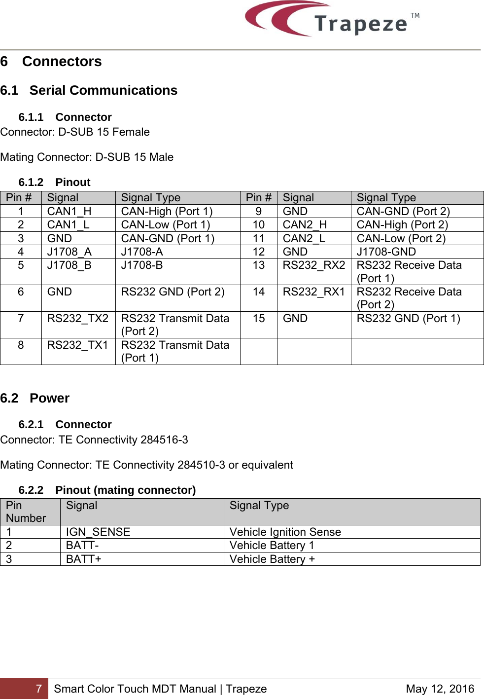
![4 Smart Color Touch MDT Manual | Trapeze May 12, 2016 1 Overview This document is to provide the specifications and recommendations for the interconnection of the Smart Color Touch MDT. 2 References [1] SAE J1708 Serial Data Communication Between Microcomputer Systems in Heavy-Duty Vehicle Applications Aug 2004 [2] SAE 1939-11 Physical Layer, 250K bits/s, Twisted Shielded Pair Oct 1999 [3] Telit Jupiter JF2 Datasheet [4] IEEE 802.3 3 Acronyms Acronym Meaning DC Direct Current EMI Electromagnetic Interference FCC Federal Communications Commission GPS Global Positioning System IEEE Institute of Electrical and Electronic Engineers, Inc. LAN Local Area Network MTBF Mean Time Before Failure RMS Root mean square USB Universal Serial Bus Wi-Fi Wireless network based on IEEE 802.11](https://usermanual.wiki/Trapeze-Software-Group/50T0148B/User-Guide-3282141-Page-4.png)
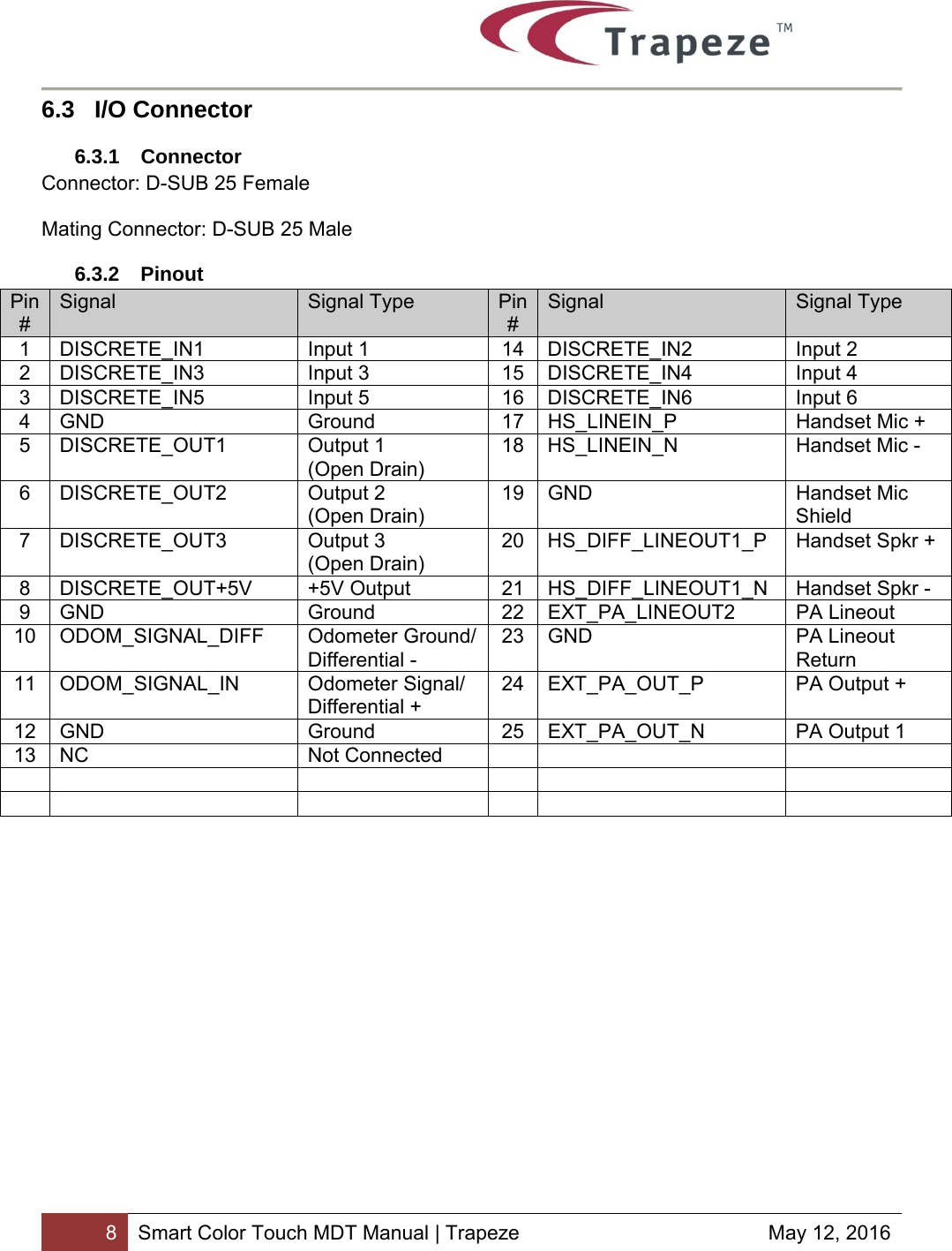
![10 Smart Color Touch MDT Manual | Trapeze May 12, 2016 8.3.2 24V Systems Maximum voltages: -3 to +32V with the bus idle 8.4 Digital Inputs VIL < 0.5V and VIH 1.2V. These inputs are protected with 47K of series resistance. Transients to 60V can be tolerated with circuit damage becoming more likely above 60V. 8.5 Digital Outputs Three open drain outputs with a sink current fused at .5A hold current and 1A trip current. One +5V output with a source current fuse at .5A hold current and 1A trip current. 8.6 Audio The internal speaker is an 8 ohm speaker rated to 2W, 200 – 20,000 Hz. The external speaker PA can drive a 4 or 8 ohm speaker up to 15W, 200 – 20,000 Hz. Two microphones, one omnidirectional and one unidirectional (software selectable) with a sensitivity of -46 dB +/-3dB. 8.7 GPS The Smart Color Touch MDT uses an active external GPS antenna. Specifications taken from Telit Jupiter JF2 Datasheet [3]. Channels 48 Sensitivity To -163 dBm Heading 0.01 deg Velocity 0.01 m/s Accuracy 2.5 m Acquisition Rate Cold start: 35s, average Hot start: 1s, average Protocol NMEA and OSP 8.8 Wi-Fi The Smart Color Touch MDT uses an internal half-size mini PCIe Wi-Fi module with external antenna. This supports 802.11 b/g/n and WEP, WPA, and WPA2 encryption.](https://usermanual.wiki/Trapeze-Software-Group/50T0148B/User-Guide-3282141-Page-10.png)