Trapeze Software Group BBX0A01 MultiConnect wireless GPS unit w/ AVL capability User Manual BBX Hardware Install Guide
Trapeze Software Group, Inc. MultiConnect wireless GPS unit w/ AVL capability BBX Hardware Install Guide
Contents
- 1. users manual
- 2. USERS MANUAL
USERS MANUAL

Hardware Installation
Guide
MultiConnect

MultiConnectHardwareInstallationGuide 1_2.doc
April 8, 2004
Page 1 of 17
Suite 230, 2891 Sunridge Way NE, Calgary Alberta, T1Y 7K7 ♦ Phone: (403) 777-3760 ♦ Fax: (403) 777-3769
TABLE OF CONTENTS
Table of Contents ..........................................................................................................................................1
Introduction....................................................................................................................................................3
1 Revision Tracking................................................................................................................................3
2 General Precautions ...........................................................................................................................3
FCC Compliance Statement (USA) ...............................................................................................................5
1 FCC Class B Part 15...........................................................................................................................5
Emissions Compliance (Canada) ..................................................................................................................5
1 MultiConnect: ICES-003, Class B .......................................................................................................5
Pour Les Utilisateurs Au Canada...................................................................................................................5
1 MultiConnect: NMB-003, Classe B......................................................................................................5
Required Items ..............................................................................................................................................5
Installation......................................................................................................................................................7
1 General ...............................................................................................................................................7
2 MultiConnect Mounting Plate ..............................................................................................................9
3 MultiConnect Connections ................................................................................................................10
4 Cabling..............................................................................................................................................11
5 Communications Device ...................................................................................................................12
6 Antenna Installation ..........................................................................................................................12
RF Radiation Specs.....................................................................................................................................14
1 FCC Radio Frequency Exposure Rules ............................................................................................14
2 How to Comply with FCC SAR/MPE Guidelines ...............................................................................14
3 SAR and MPE Limits.........................................................................................................................14
4 Labeling ............................................................................................................................................14
Basic Operation ...........................................................................................................................................16
1 Turning MultiConnect On ..................................................................................................................16
2 General Handling and Maintenance..................................................................................................16
MULTICONNECT Technical Data................................................................................................................17
1 Voltage..............................................................................................................................................17
2 Current Consumption........................................................................................................................17
3 Temperature Range..........................................................................................................................17
4 Dimensions and Weight....................................................................................................................17

MultiConnectHardwareInstallationGuide 1_2.doc
April 8, 2004
Page 2 of 17
Suite 230, 2891 Sunridge Way NE, Calgary Alberta, T1Y 7K7 ♦ Phone: (403) 777-3760 ♦ Fax: (403) 777-3769
5 Compliance .......................................................................................................................................17

MultiConnectHardwareInstallationGuide 1_2.doc
April 8, 2004
Page 3 of 17
Suite 230, 2891 Sunridge Way NE, Calgary Alberta, T1Y 7K7 ♦ Phone: (403) 777-3760 ♦ Fax: (403) 777-3769
INTRODUCTION
This document provides instructions and guidelines that should be followed for the
successful installation of a Mentor MultiConnect.
1 Revision Tracking
Date Description Revision Initials
March 15, 2004 Initial Release 1.0 JK
March 31, 2004 Updated compliance to FCC Class B 1.1 JK
Added Canadian Compliance Statements
April 8, 2004 Added additional safety warning to FCC statements 1.2 JK
2 General Precautions
Before using this product, be sure to carefully read all operating instructions. Save
these instructions for future reference. Also be sure to heed all the warnings located
throughout this document.
NOTE
Mentor Engineering Inc. reserves the right to change specifications without notice.
Please ensure you have the most recent revision of this Document
CAUTION
Use only a damp cloth for cleaning. Never use any type of liquid or aerosol cleaner, or
any type of organic solvent to clean this product.
CAUTION
Only qualified, trained personnel should service the MultiConnect unit. Attempting to
remove the cover or disassemble the product could expose you to dangerous high
voltage points.

MultiConnectHardwareInstallationGuide 1_2.doc
April 8, 2004
Page 4 of 17
Suite 230, 2891 Sunridge Way NE, Calgary Alberta, T1Y 7K7 ♦ Phone: (403) 777-3760 ♦ Fax: (403) 777-3769
WARNING
To avoid the risk of electric shock, never expose this product to water or operate in a
high humidity environment. Never use the product around water (near a bathtub,
kitchen sink, swimming pool or in the rain).
WARNING
Do not attempt to operate a damaged device. If the product has been exposed to
water, shows evidence of physical damage or is not operating properly unplug it from
the power source and refer servicing to qualified service personnel.

MultiConnectHardwareInstallationGuide 1_2.doc
April 8, 2004
Page 5 of 17
Suite 230, 2891 Sunridge Way NE, Calgary Alberta, T1Y 7K7 ♦ Phone: (403) 777-3760 ♦ Fax: (403) 777-3769
FCC COMPLIANCE STATEMENT (USA)
1 FCC Class B Part 15
This device complies with Part 15 of FCC Rules. Operation is subject to the following two
conditions:
1. This device may not cause harmful interference
2. This device must accept any interference received, including interference that
may cause undesired operation.
NOTE: This equipment has been tested and found to comply with the limits for a Class B
digital device, pursuant to Part 15 of the FCC Rules. These limits are designed to provide
reasonable protection against harmful interference when the equipment is operated in a
residential environment. This equipment generates, uses, and can radiate radio
frequency energy and, if not installed and used in accordance with the instruction manual,
may cause harmful interference to radio communications, in which case the user will be
required to correct the interference at their own expense.
The user of this equipment is cautioned that changes or modifications not expressly
approved by the party responsible for compliance could void the user’s authority to
operate the equipment.
EMISSIONS COMPLIANCE (CANADA)
1 MultiConnect: ICES-003, Class B
This Class B digital apparatus meets all requirements of the Canadian Interference-
Causing Equipment Regulations.
POUR LES UTILISATEURS AU CANADA
1 MultiConnect: NMB-003, Classe B
Cet appareil numerique de la categorie B est conforme a la legislation Canadienne sur les
appareils generateurs de parasites.
REQUIRED ITEMS
For a typical installation in a vehicle, following items will be needed:
• MultiConnect Unit
• MultiConnect Power cable(s)
• In-line Cable Fuses
• Mounting Plate and Thumbscrews
• Mounting Plate Hardware (Not Supplied)
To assist with the installation, it is often necessary to have the following available:

MultiConnectHardwareInstallationGuide 1_2.doc
April 8, 2004
Page 6 of 17
Suite 230, 2891 Sunridge Way NE, Calgary Alberta, T1Y 7K7 ♦ Phone: (403) 777-3760 ♦ Fax: (403) 777-3769
• Laptop PC
• MultiConnect Debugging Cable
• Multimeter

MultiConnectHardwareInstallationGuide 1_2.doc
April 8, 2004
Page 7 of 17
Suite 230, 2891 Sunridge Way NE, Calgary Alberta, T1Y 7K7 ♦ Phone: (403) 777-3760 ♦ Fax: (403) 777-3769
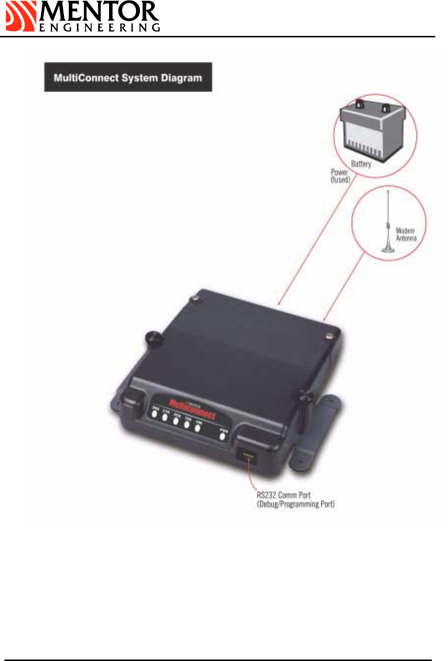
INSTALLATION
1 General
The MulitConnect is an external modem that can interface to any type of host via an
RS232 interface. It is designed to be installed inside of a vehicle. It can be equipped with
several different RF Modems. An RS232 RJ45 port is also available for operator
debugging.
MultiConnectHardwareInstallationGuide 1_2.doc
April 8, 2004
Page 8 of 17
Suite 230, 2891 Sunridge Way NE, Calgary Alberta, T1Y 7K7 ♦ Phone: (403) 777-3760 ♦ Fax: (403) 777-3769
Figure 1: Typical System Schematic
MultiConnectHardwareInstallationGuide 1_2.doc
April 8, 2004
Page 9 of 17
Suite 230, 2891 Sunridge Way NE, Calgary Alberta, T1Y 7K7 ♦ Phone: (403) 777-3760 ♦ Fax: (403) 777-3769
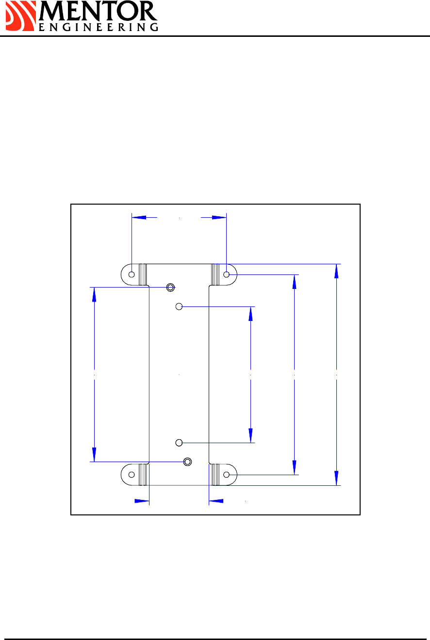
2 MultiConnect Mounting Plate
The Mounting Plate is supplied with each unit, and allows the MultiConnect to be mounted
in a variety of locations and orientations. The mounting location is application specific.
The MultiConnect does not have an interactive user interface and thus can be installed
out of sight (i.e. under a car seat, or in the trunk). Installing the MultiConnect out of sight
not only increases the aesthetic properties of the installation but also limits the access by
drivers and passengers to the cabling.
The Mounting plate is first fastened to the car interior using bolts or other appropriate
means. Hardware has not been supplied for this step as it will vary depending on the
thickness and type of material the mounting plate is attached to. The MultiConnect unit
can then be attached to the mounting plate using the supplied thumbscrews.
5.1200" 6.5000"4.0000"
1.7500"
2.7750"
5.8750"
Figure 1: Mounting Plate Dimensions
Mounting Hardware:
• Mounting Plate and Thumbscrews (supplied)
• Mounting Plate Hardware (not supplied)
4 x 0.17” Mounting Holes (Fits most #8 fasteners)
MultiConnectHardwareInstallationGuide 1_2.doc
April 8, 2004
Page 10 of 17
Suite 230, 2891 Sunridge Way NE, Calgary Alberta, T1Y 7K7 ♦ Phone: (403) 777-3760 ♦ Fax: (403) 777-3769
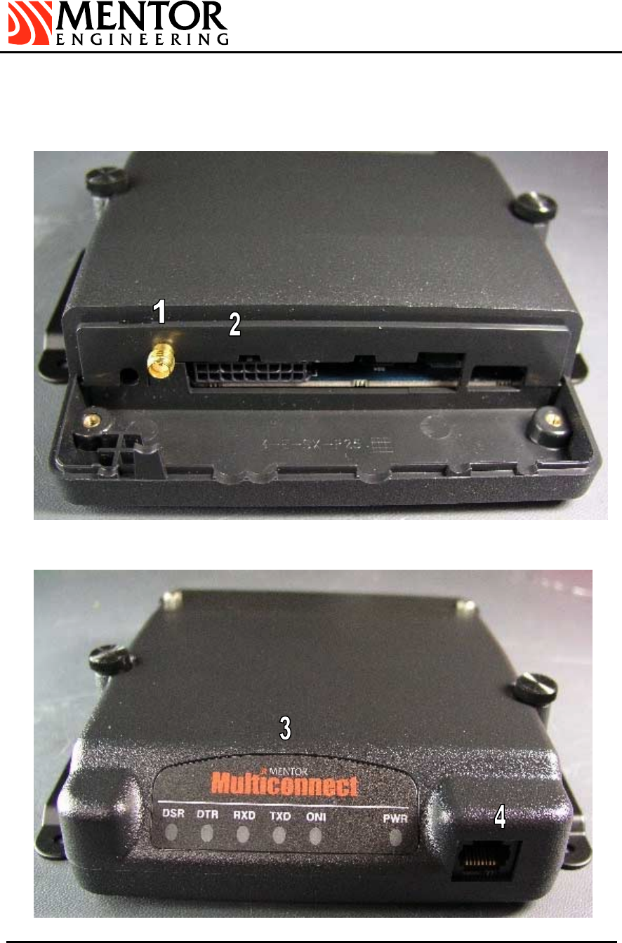
3 MultiConnect Connections
The cable cover on the MultiConnect unit can be removed by hand or by using a flathead
screwdriver to loosen the two screws. Removing the cable cover gives access to the
MultiConnect interface points, which are detailed below.
Figure 2: MultiConnect Interface points (Rear View)

MultiConnectHardwareInstallationGuide 1_2.doc
April 8, 2004
Page 11 of 17
Suite 230, 2891 Sunridge Way NE, Calgary Alberta, T1Y 7K7 ♦ Phone: (403) 777-3760 ♦ Fax: (403) 777-3769
Figure 3: MultiConnect Interface points (Front View)
3.1 Interface Summary
1. Straight SMA Connector
Modem Antenna
2. 18pin Micro Fit Connector (MOLEX 43045-1806)
Power, Ignition Sense and Vehicle I/O
3. User Interface
LEDs to indicate – DSR, DTR, RXD, TXD, ONI (modem on), PWR (IGN on).
4. 8 position Modular Jack - RJ45 (AMP 406525-1)
RS232 Comm/Debug Port
3.2 Vehicle Interface
Details regarding the cabling interface for external MultiConnect host devices (Mentor
Engineering’s MDC or a PC for instance), are available as application notes specific
to these functions. These notes are provided as required by Mentor Engineering, Inc.
See Interface Point #2 above.
4 Cabling
The MultiConnect receives power via the Mentor supplied power cable (4-CAS-
BBXVEHC075-00). Power and Ignition Sense lines need to be installed with the in-line
fuses provided. See cable pin-out for details.
It is common practice to route the cabling through the vehicle so it is not visible to the
driver and is protected from the environment. Mentor Engineering recommends that this
practice be followed in all installations.
If an external host device (i.e. an MDC) is being used with the MultiConnect, the installer
must ensure that there is a common ground between the devices. MultiConnect power
leads can be crimped onto the power leads at the power input to the host device.
Installing the power leads in this way will avoid the possibility of the ground potential at
MultiConnect differing from the ground potential of the host device (due to current draw
during a transmit cycle).
The MultiConnect should be installed to unswitched power. The unit can use the ignition
line to power on and off automatically, or it can use a power control input so that the host
device determines when the MultiConnect is on. The two methods can also be used in
conjunction with each other.
The in-line power fuse is a 3-amp MINI blade fuse (2-FUS-MINI003A-01). The power fuse
must be installed within 4” of the Vehicle Battery. The in-line ignition fuse is a 2-amp MINI
blade fuse (2-FUS-MINI002A-01). The Vehicle ignition line must be fused with the in-line
fuse provided or through the vehicle fuse box.
Note, a blown fuse will often indicate that there is either a problem with a connection to
the MultiConnect or with the MultiConnect itself. Check all connections before replacing a
fuse.
MultiConnectHardwareInstallationGuide 1_2.doc
April 8, 2004
Page 12 of 17
Suite 230, 2891 Sunridge Way NE, Calgary Alberta, T1Y 7K7 ♦ Phone: (403) 777-3760 ♦ Fax: (403) 777-3769
CAUTION
For continued protection against risk of fire and equipment damage, replace only with
the correct type and rating of fuse.
Please refer to the Technical Data section of this manual for details on the voltage and
current requirements of MultiConnect.
5 Communications Device
The MultiConnect can incorporate a variety of internal data modems such as GPRS,
iDEN, CDPD, etc.
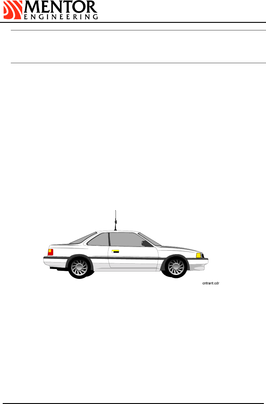
6 Antenna Installation
Antenna location has an extremely significant impact on the performance of a wireless
modem. Mentor Engineering recommends using a roof top antenna installed in the center
of the vehicle roof for best coverage and to meet SAR/MPE radiation specifications (See
Following section: RF Radiation Specifications).
Antenna installation requirements vary between different antennas. Contact Mentor for
specific Antenna information for your application. The following Figure shows the
preferred location of a rooftop antenna.
Figure 4: Location of Roof Mount Antenna
6.1 General Antenna Guidelines
• Position the antenna as high as possible on the body of the vehicle.
• Keep the RF cable as short as possible. Cut the excess cable during an
installation. Do not wrap it up. Excess cable adds unnecessary loss to the
signal.
• Ensure the antenna is in a vertical position during operation.
• Use proper RF connectors. Use a straight SMA connector when using a
MultiConnect. (Refer to the SMA Connector Assembly documentation
provided)

MultiConnectHardwareInstallationGuide 1_2.doc
April 8, 2004
Page 13 of 17
Suite 230, 2891 Sunridge Way NE, Calgary Alberta, T1Y 7K7 ♦ Phone: (403) 777-3760 ♦ Fax: (403) 777-3769
WARNING
Improper installation of the SMA connector can cause damage to the mating SMA
connector on the MultiConnect unit.
• Avoid sharp bends and moving objects in the coaxial cable path.
• Position the antenna away from fuel caps.
• Position the antenna such that there is separation from other antennas (e.g.
AM/FM Radio, cellular etc.).
• Follow the antenna manufacturer's guidelines exactly when installing
antennas.
WARNING
The MultiConnect, must be used with a Mentor authorized antenna in order to comply
with FCC regulations. Improper antenna selection or positioning may result in
excessive RF exposure which could harm the user.

MultiConnectHardwareInstallationGuide 1_2.doc
April 8, 2004
Page 14 of 17
Suite 230, 2891 Sunridge Way NE, Calgary Alberta, T1Y 7K7 ♦ Phone: (403) 777-3760 ♦ Fax: (403) 777-3769
RF RADIATION SPECS
1 FCC Radio Frequency Exposure Rules
Based on FCC rules 2.1091 and 2.1093 and FCC Guidelines for Human Exposure to
Radio Frequency Electromagnetic Fields, OET Bulletin 65 and its Supplement C, all radio
units are subject to routine environmental evaluation for radio-frequency (RF) exposure
prior to equipment authorization or use.
For mobile devices, defined as a transmitting device designed to be generally used such
that a separation distance of at least 25 cm is maintained between the body of the user
and the transmitting radiated structure, the human exposure to RF radiation can be
evaluated in terms of Maximum Permissible Exposure (MPE) limits for field strength or
power density in mW/cm2.
2 How to Comply with FCC SAR/MPE Guidelines
In order to comply with FCC SAR/MPE Guidelines the antenna must be placed a
minimum of 25 cm from the vehicles edge. To accomplish this, and to ensure optimum
antenna performance Mentor Engineering recommends that antenna be installed in the
center of the vehicle rooftop.
WARNING
The user should be instructed to maintain the minimum distance from the antenna.
3 SAR and MPE Limits
SAR limits for General Population/Uncontrolled exposure is 1.6W/kg for partial body
exposure, averaged over 1 g of tissue and 4 W/kg for hands, wrists and feet averaged
over 10 g of tissue. The limits for Occupational/Controlled exposure are more relaxed, i.e.
8 W/kg for partial body and 20 W/kg for hands, wrists and feet. The 1.6 W/kg limit applies
for most MultiConnect applications.
The limit for MPE is 0.6mW/cm2 at 900 MHz.
RF exposure distance is based on normal operating proximity to the user’s or nearby
persons’ body. This distance is measured from any part of a radiating structure, generally
the antenna, to the closest part of the body.
4 Labeling
If the antenna is installed at least 25 cm from the vehicle’s edge no warning label is
required.
If the antenna is not at least 25 cm from any vehicle edge, an additional RF radiation
hazard label that warns the user or nearby persons to keep away from the antenna by the
specified distance is required. This is because the minimum separation distance of the

MultiConnectHardwareInstallationGuide 1_2.doc
April 8, 2004
Page 15 of 17
Suite 230, 2891 Sunridge Way NE, Calgary Alberta, T1Y 7K7 ♦ Phone: (403) 777-3760 ♦ Fax: (403) 777-3769
final device configuration cannot be met due to occasional non-essential operating
conditions or requirements.
An example statement is shown below.
“Warning: To meet the FCC RF exposure requirement for mobile
transmitter end products, ensure that the antenna is at least 25 cm (10”)
away from the user, or nearby persons, when transmitting.”

MultiConnectHardwareInstallationGuide 1_2.doc
April 8, 2004
Page 16 of 17
Suite 230, 2891 Sunridge Way NE, Calgary Alberta, T1Y 7K7 ♦ Phone: (403) 777-3760 ♦ Fax: (403) 777-3769
BASIC OPERATION
1 Turning MultiConnect On
Unit behaviour is dependant on the internal modem type and typical operation will vary.
However, the unit generally turns on when the vehicle ignition line is active or when the
Debug Cable is inserted.
2 General Handling and Maintenance
Care should be taken in handling the MultiConnect to prolong product life. Caution should
be used to prevent liquids from entering any openings on the unit. Liquid spills could
seriously damage the internal contents of the unit.
2.1 Cleaning Tips
Use a soft lint free cloth moistened with water or mild detergent to clean the exterior
of the unit. Do not apply cleaner directly to any unit opening.

MultiConnectHardwareInstallationGuide 1_2.doc
April 8, 2004
Page 17 of 17
Suite 230, 2891 Sunridge Way NE, Calgary Alberta, T1Y 7K7 ♦ Phone: (403) 777-3760 ♦ Fax: (403) 777-3769
MULTICONNECT TECHNICAL DATA
1 Voltage
Supply voltage 9 - 34 volts
2 Current Consumption
Standby 0.7mA
Typical† 25mA
Peak¥ 3A
3 Temperature Range
Operating -30 to +60°C
-22 to +140°F
WARNING
Operation at temperatures outside this range in not recommended. Some modems
are not intended for operation at the extremes.
Storage -40 to +80°C
-40 to +176°F
4 Dimensions and Weight
Approximate Size (L x W x H) 4.75” x 5.0” x 1.0”
121 x 127 x 25 mm
Weight (with typical modem) 0.77 lbs / 0.35 kg
5 Compliance
• FCC Class A Part 15
NOTE
Mentor Engineering Inc. reserves the right to change specifications without notice.
† Typical Current Draw measured with device powered without a modem.
¥ Peak Current draw will vary depending on Modem type and peripheral devices used.