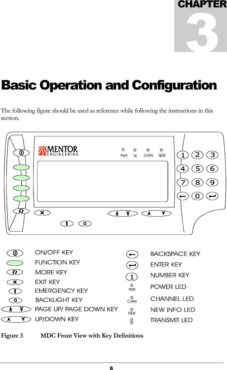
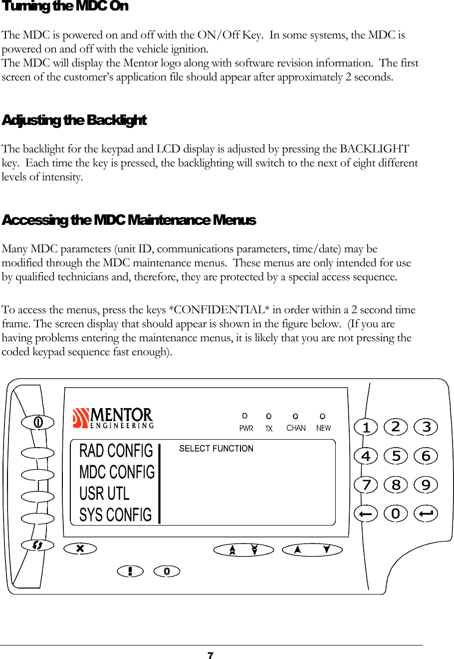
Trapeze Software Group MDC0R01 MDC is a wireless GPS unit and AVL Device User Manual hardware installation guide
Trapeze Software Group, Inc. MDC is a wireless GPS unit and AVL Device hardware installation guide
Contents
- 1. hardware installation guide
- 2. users manual
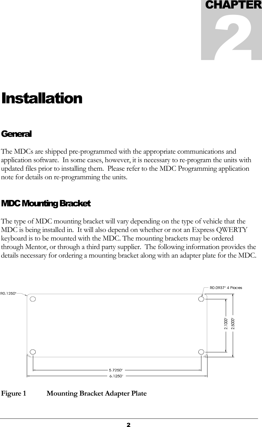
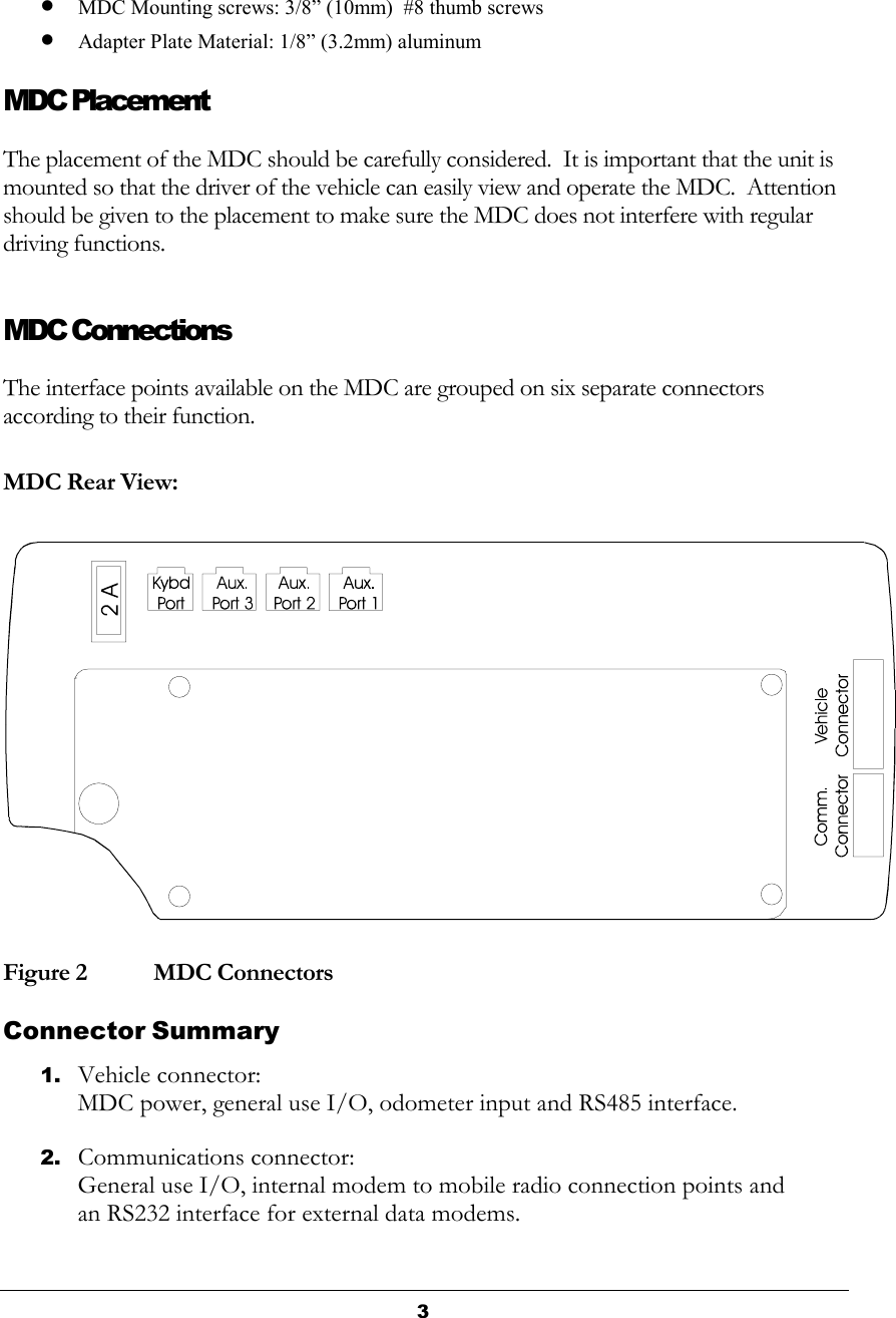
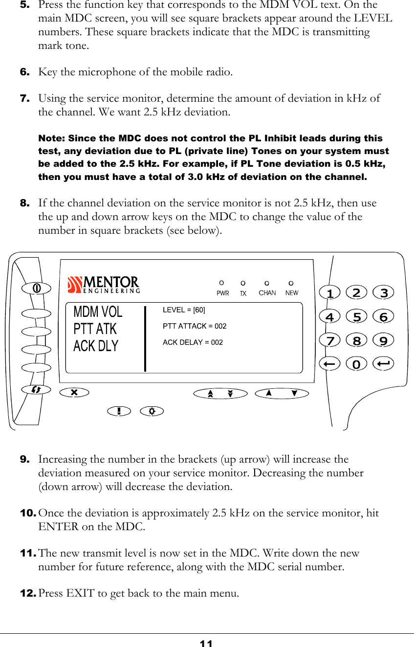
hardware installation guide