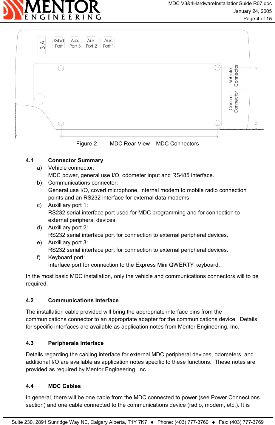
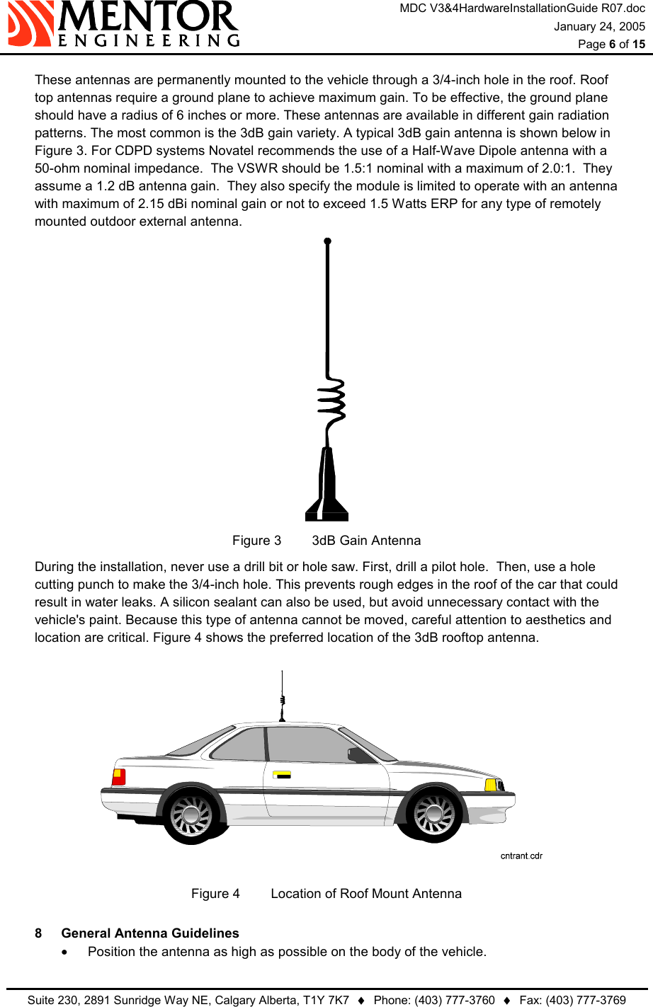
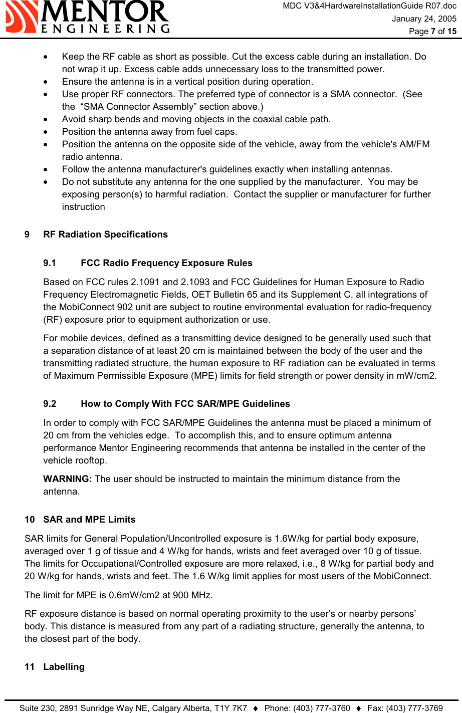
Trapeze Software Group MDC0V01 Wireless mobile data computer with GPS and AVL User Manual Installation guide
Trapeze Software Group, Inc. Wireless mobile data computer with GPS and AVL Installation guide
UserManual.wiki
>
Trapeze Software Group
>
MDC0V01 User Manual
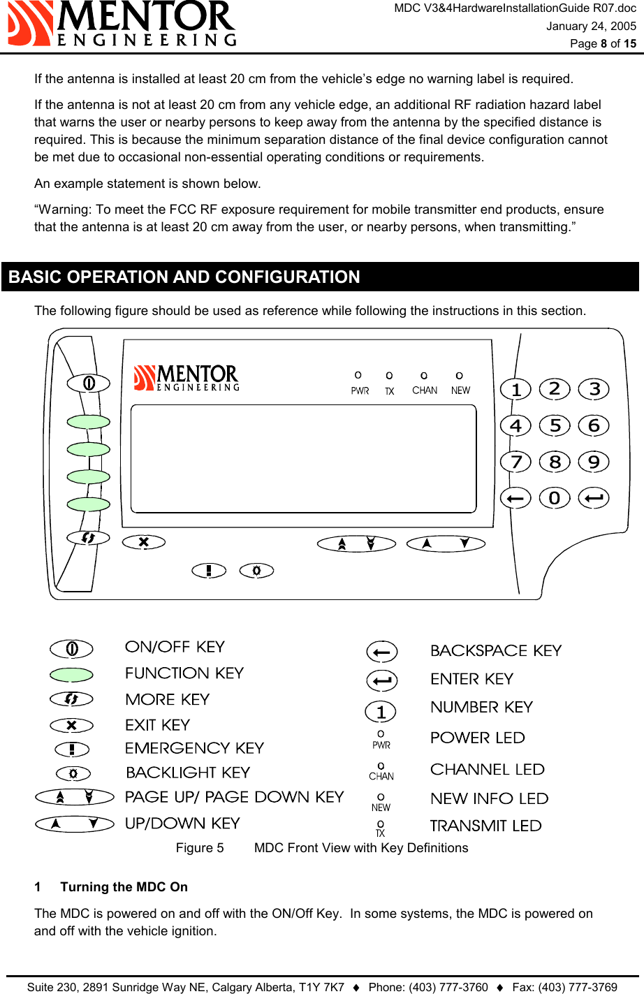
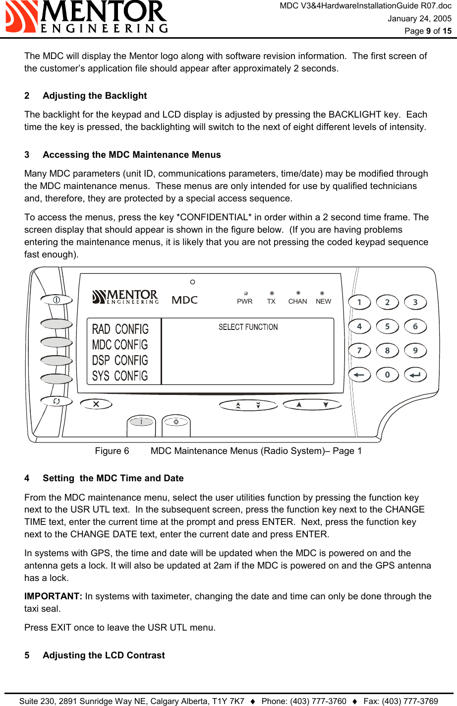
Installation guide
Navigation menu
Upload a User Manual
Namespaces
Wiki Guide
HTML
PDF
Info
Views
User Manual
Discussion / Help
Navigation