Trapeze Software Group RAN44N1 Rugged and compact vehicular computer User Manual
Trapeze Software Group, Inc. Rugged and compact vehicular computer
UserManual.wiki
>
Trapeze Software Group
>
RAN44N1 User Manual
>
User Manual
Contents
1.
User Manual
2.
Users Manual
User Manual
Navigation menu
Upload a User Manual
Namespaces
Wiki Guide
HTML
PDF
Info
Views
User Manual
Discussion / Help
Navigation


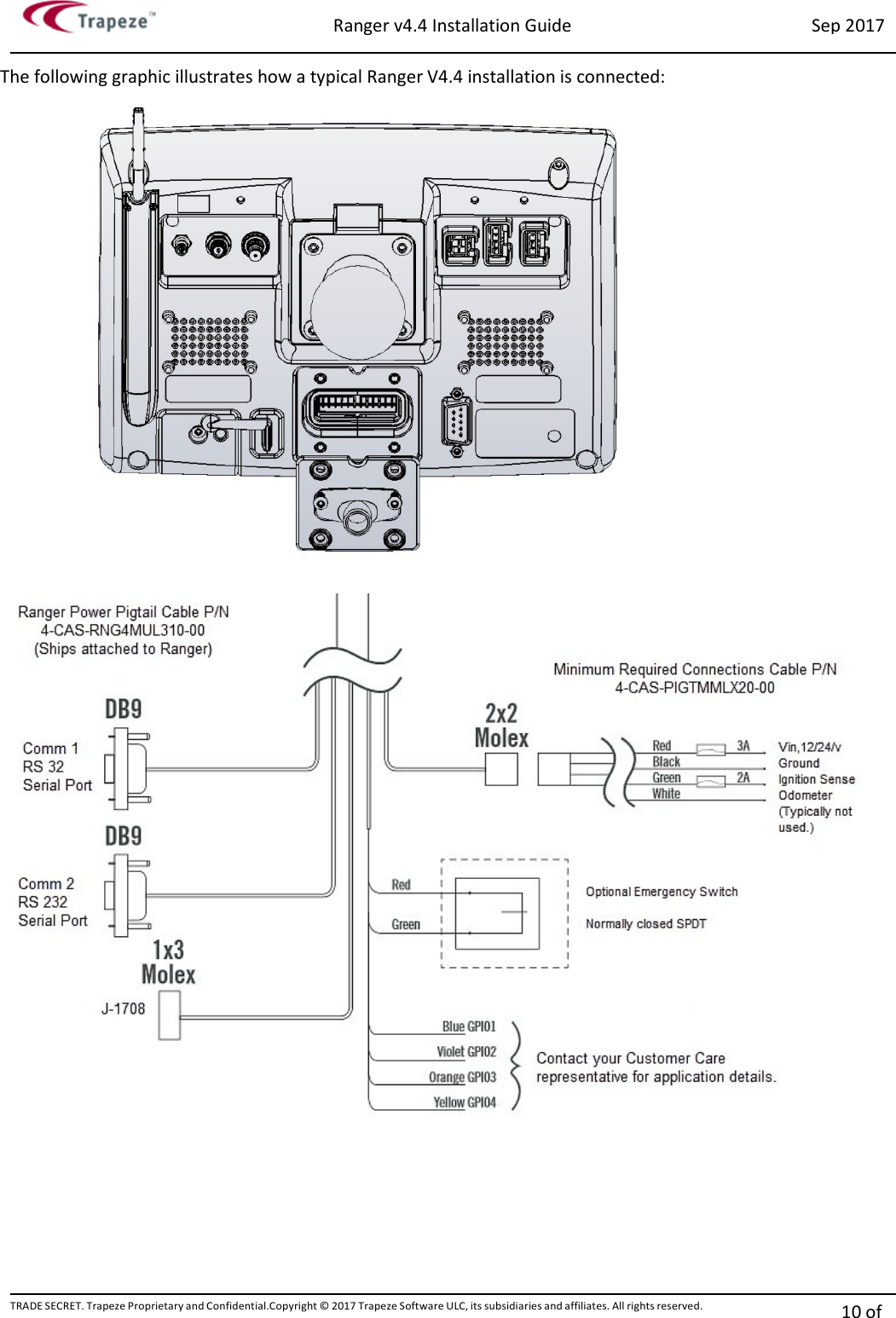

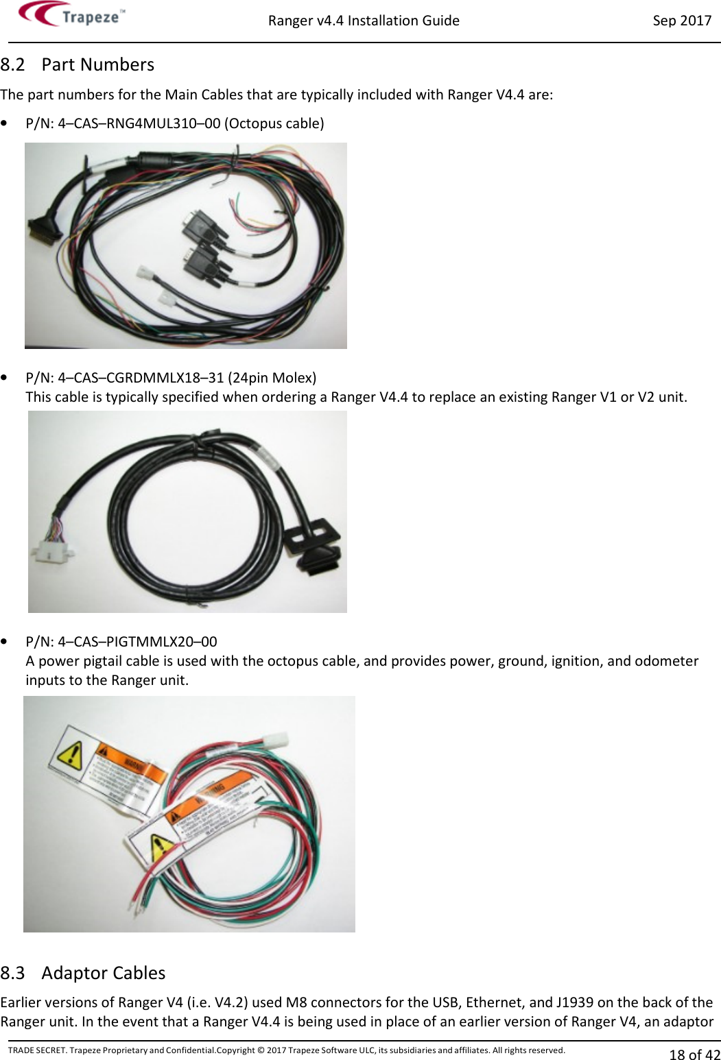
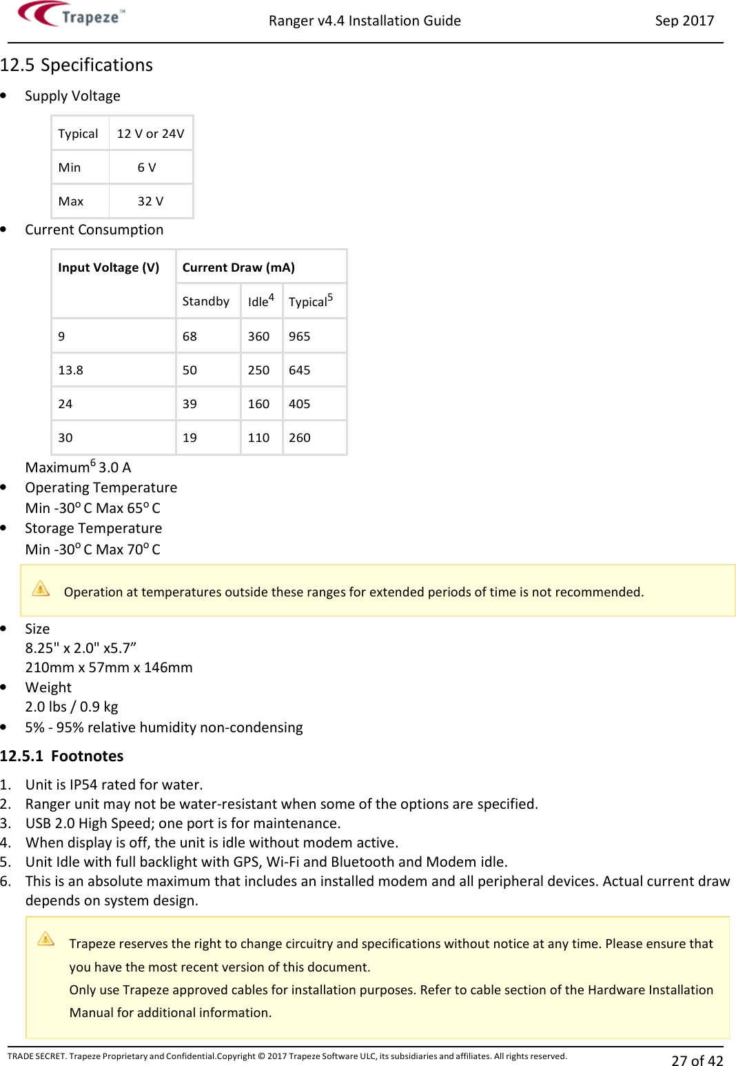
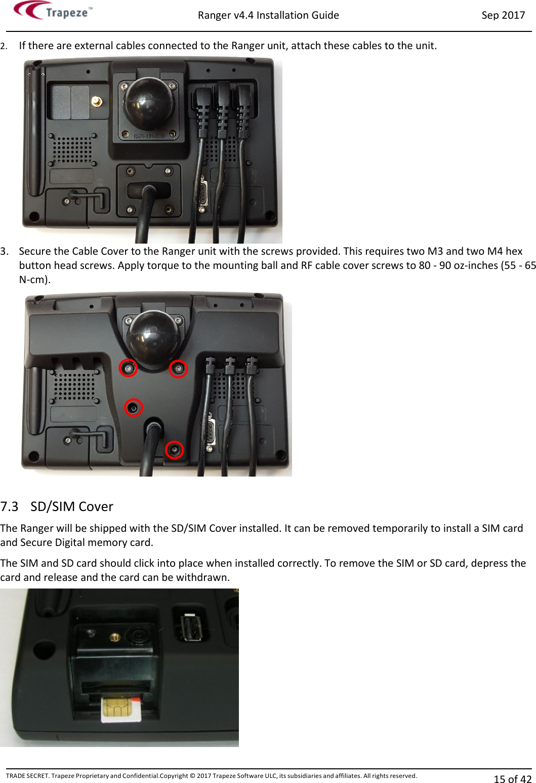
![Ranger v4.4 Installation Guide Sep 2017 TRADE SECRET. Trapeze Proprietary and Confidential.Copyright © 2017 Trapeze Software ULC, its subsidiaries and affiliates. All rights reserved. 14 of 42 7 Installing the Ranger Cables and Cable Cover The Ranger unit is shipped with a cable cover installed to provide tamper resistance, which can be removed with a 2mm and 2.5mm hex bit. If the cable cover needs to be reinstalled at some point, do so according to the steps described in the following procedure. 7.1 Torque Settings Trapeze recommends that the screws that are used to affix the Cable Cover Plate, Cable Cover and SD/SIM Cover be installed to a specific torque level. Excessive or insufficient torque can lead to product damage and/or failure. Trapeze recommends using a calibrated torque screwdriver for tightening these screws. To install the Ranger Cable Cover, the following items are used: • Ranger Cable Cover • M4 x 12.5mm HEX Button Head Screw (Quantity 2) • M3 x 8mm hex head screw (Quantity 4) • Hex bits, 2mm and 2.5mm [Not Included] • 5/16” driver (torque driver preferred) [Not Included] 7.2 Cable Cover To install the Ranger Cable Cover: 1. Connect the Ranger power cable to the power input. Use two M3 screws as shown in the following graphic to fasten the Power Cable Cover Plate. Apply torque to the main cable cover screws to 80 - 90 oz-inches (55 - 65 N-cm).](https://usermanual.wiki/Trapeze-Software-Group/RAN44N1.User-Manual/User-Guide-3608057-Page-14.png)
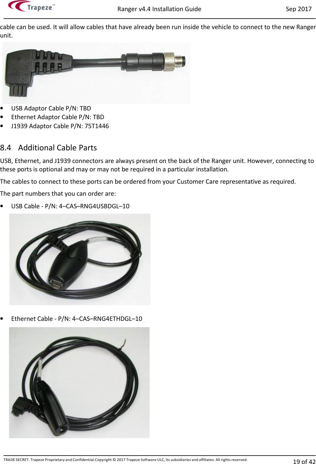
![Ranger v4.4 Installation Guide Sep 2017 TRADE SECRET. Trapeze Proprietary and Confidential.Copyright © 2017 Trapeze Software ULC, its subsidiaries and affiliates. All rights reserved. 17 of 42 8 Ranger Configurations and Optional Parts Ranger has several optional configurations that are implemented during the assembly of the unit at the factory. The full list of these options are explained in the following sections. The Ranger part number label on the back of the unit can be interpreted to give configuration details for that particular unit. 8.1 Unit Numbering Structure The following list explains the different characters of the part number label to determine what options are included with any specific Ranger. (This numbering format is subject to change.) Numbering is in the format “R44-12345–67” (Example: “R44-N11T-01”) Number Description 1st and 2nd Character N1= PTCRB variant (For use on many PTCRB member carrier networks) V1 = Verizon variant 3rd Character 0 = Without Bluetooth and WLAN 1 = With Bluetooth and WLAN 4rd Character 0 = No additional options 1 = Rear view camera input 2 = Magnetic card reader 4 = External GPS antenna port X = Sum of above selected options (e.g. 2+4=6 is Mag card reader plus External GPS antenna port. 5th Character T = Trapeze Logo A = AssetWorks Logo B = Blank – No Logo 6th Character 0 = Window CE6 7th Character 0 = Main Cable Terminated with 24 Pin Molex connector [4–CAS–CGRDMMLX18–31] 1 = Main Cable with Multiple Terminations (Octopus) [4–CAS–RNG4MUL310–00] 2 = Supplied without Main Cable](https://usermanual.wiki/Trapeze-Software-Group/RAN44N1.User-Manual/User-Guide-3608057-Page-17.png)