Trapeze Software Group RAN4661 Rugged and Compact Vehicular Computer User Manual user guide
Trapeze Software Group, Inc. Rugged and Compact Vehicular Computer user guide
UserManual.wiki
>
Trapeze Software Group
>
RAN4661 User Manual
>
user guide
Contents
1.
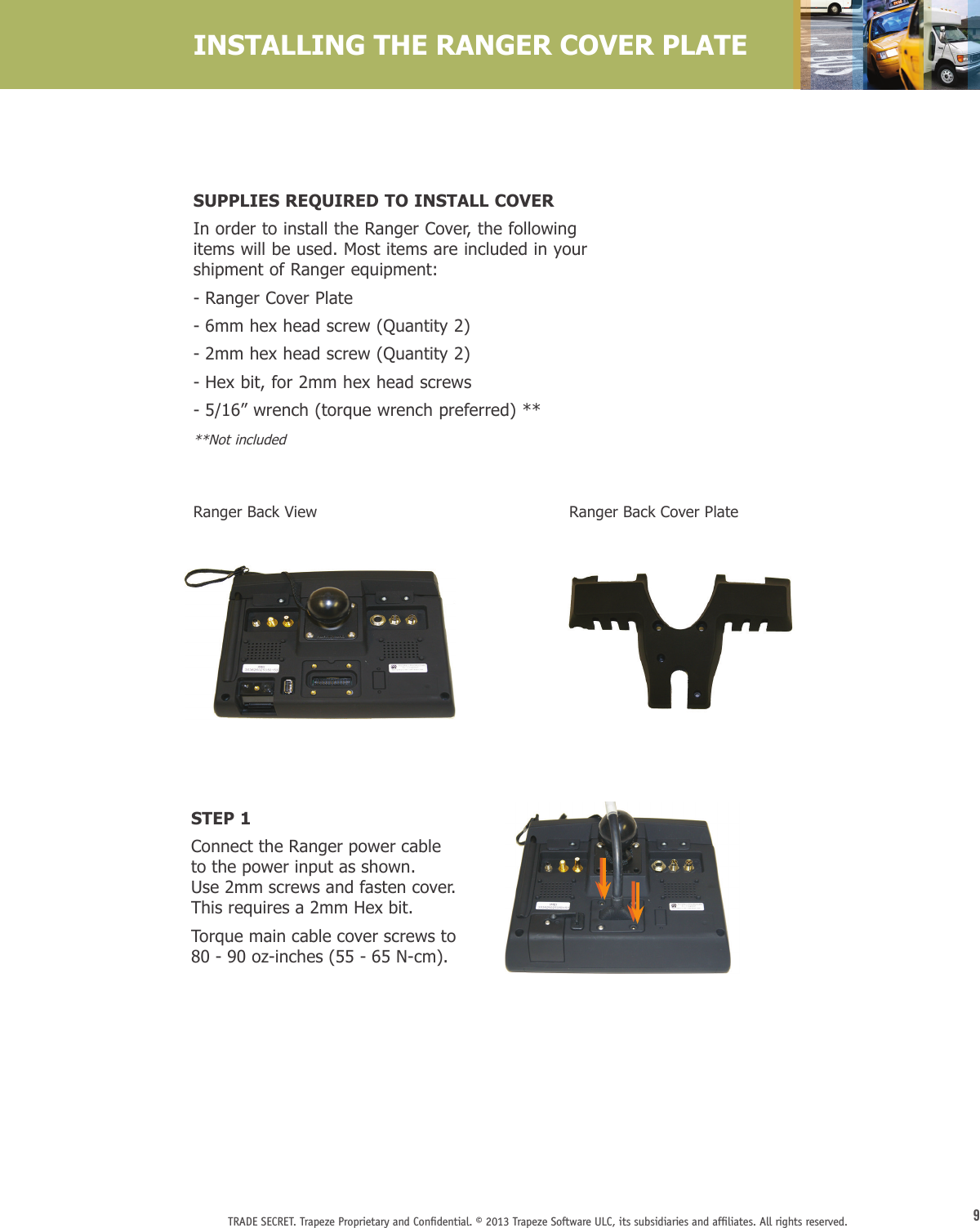
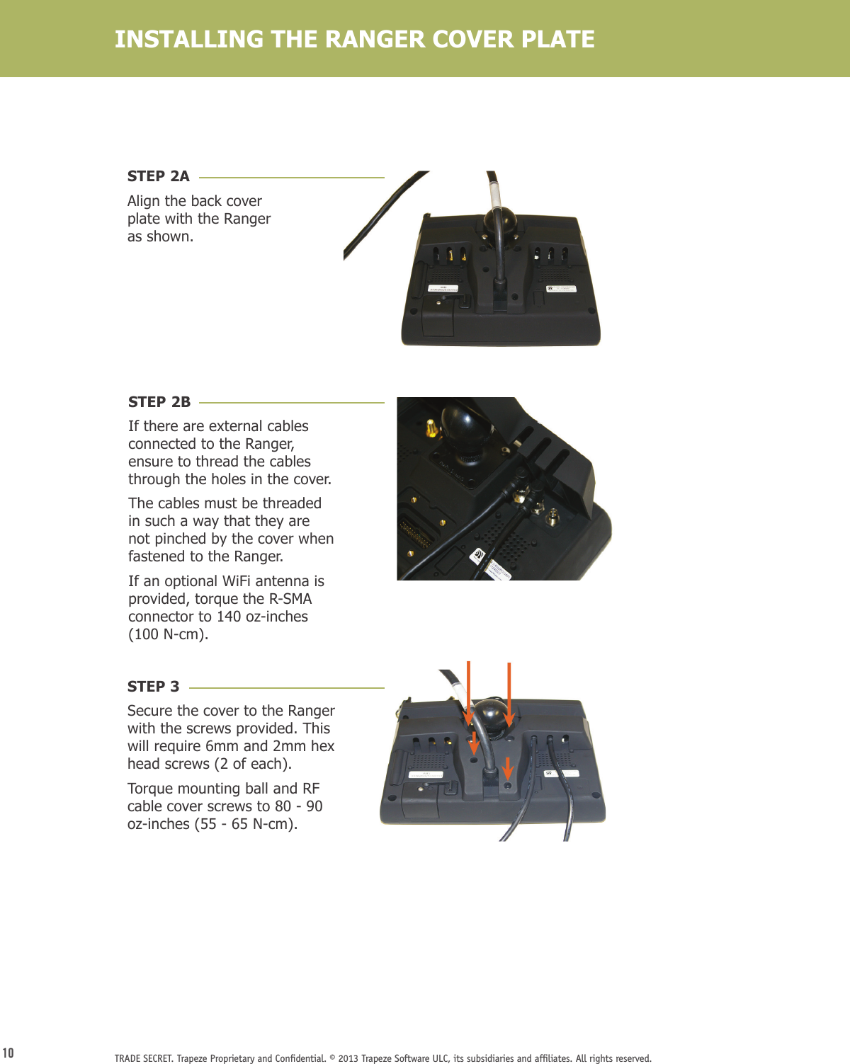
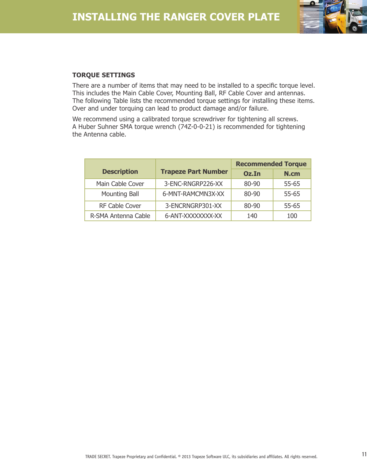
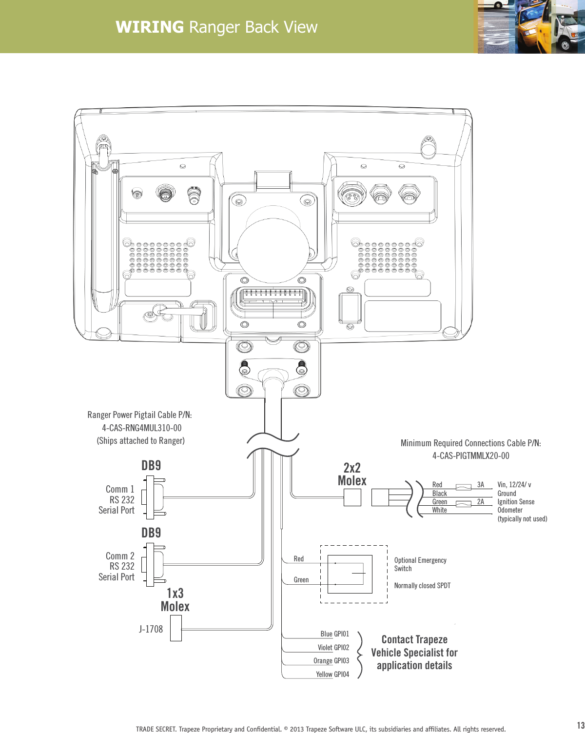
user guide
2.
user manual
user guide
Navigation menu
Upload a User Manual
Namespaces
Wiki Guide
HTML
PDF
Info
Views
User Manual
Discussion / Help
Navigation