Trapeze Software Group RAN48790 RUGGED AND COMPACT VEHICULAR COMPUTER User Manual INSTALL GUIDE
Trapeze Software Group, Inc. RUGGED AND COMPACT VEHICULAR COMPUTER INSTALL GUIDE
Contents
- 1. USERS INFO
- 2. RAGER INSTALL GUIDE
- 3. USER GUIDE
- 4. INSTALL GUIDE
INSTALL GUIDE
Hardware Installation Guide
Copyright © 2008 Mentor Engineering Inc. All rights reserved.
Ranger 7-RNGR-04X
Ver 5.4

2
Table of ConTenTs
Safety & After-Market Equipment ........................................4
Qualified Installer ...............................................................5
Introduction .......................................................................7
Cautions .......................................................................8
Before You Begin ................................................................8
Parts List ...........................................................................9
Supplied .......................................................................10
Supplied (Optional) ........................................................11
Not Supplied .................................................................11
Mounting Locations ............................................................12
Placement .....................................................................12
Ranger Mounting Examples .................................................13
Examples of Suitable Mounting Locations .........................13
Installing The Ranger Cover Plate ........................................14
Wiring - Ranger Back View .................................................17
Connection Points ..............................................................19
1) Splicing ...................................................................19
2) Power ......................................................................19
3) Ground ....................................................................19
4) Switched Ignition Power ............................................19
5) VSS (Vehicle Speed Sensor for Odometer Pulses) .........21
6) Emergency Switch (optional) ......................................22
Cabling ..............................................................................23
1) Routing....................................................................23
2) Strain Relief .............................................................23
3) Labeling ..................................................................24
4) Connection Types ......................................................24
5) Wire Types ...............................................................25
6) Electrical Measurements ............................................25
Antennas ...........................................................................26

3
Table of ConTenTs
1) Internal Antennas .....................................................26
2) External Antennas .....................................................26
3) Cable Routing...........................................................27
4) Connectors ...............................................................28
Ranger Specs 7-RNGR-04X...............................................29
General Description ........................................................29
Standard Features ..........................................................29
Compliance and Testing ..................................................30
Optional Features ...........................................................30
Key Specifications ..........................................................30
Appendix A - Conformity .....................................................33
1) FCC Class B Part 15 .................................................33
2) IEC 60950 3rd Edition (2000) Safety of Information Tech-
nology Equipment .....................................................35
3) ISO 7637-1 Load Dump Transient ..............................35
4) MIL STD 810F: General Vibration ...............................35
5) MIL STD 810F: Shock Test ........................................35
6) IEC 60529 - IP54 ....................................................35
Appendix B - RF Radiation Specs ........................................36
RF Exposure ..................................................................36
Appendix C - Approvals .......................................................37
1) CDMA/EVDO ............................................................37
2) GSM/HSDPA ............................................................37
3) WIFI/Bluetooth Only ..................................................37

4
The use of after-market equipment in motor vehicles can
compromise a vehicle’s safety-related design characteristics,
including but not limited to:
• Airbags, including but not limited to potential obstruction of air-
bag deployment;
• Passenger compartment, including but not limited to potential for
ergonomic problems, physical obstacles, etc.; and
• Trunk/gas tank protection, including but not limited to the poten-
tial for trunk-mounted equipment to exacerbate tank vulnerability
in a rear collision.
FAILURE TO INSTALL THE EQUIPMENT
AS RECOMMENDED COULD CAUSE OR
CONTRIBUTE TO AN ACCIDENT AND RESULT
IN DAMAGE TO PROPERTY OR PERSONS.
WARNING
safeTy & afTer-MarkeT equipMenT

5
This product is to be installed by qualified installation personnel only.
The installer must be trained in industry best practices for this type of
installation. The training would include but not be limited to:
1. The appropriate methods for installing cables such that:
• The operation of the vehicle is not interfered with.
• The installation process does not damage or interfere with other
vehicle components and/or systems.
• Wiring is kept clear of sharp objects, sources of heat and any
other hazard that could damage the cable or wire.
• Wiring is secured such that it does not cause damage to other equip-
ment, itself, or interfere with the operation of other systems and
devices.
• Wiring through bulkheads is performed such that wiring does not
chafe, and a seal is maintained between compartments.
• Appropriate and industry standard fasteners, splices, connectors
and ties are used for the vehicle environment.
• Appropriate slack is in place to prevent straining of the wire, cable
or connectors.
• Any other issue that could affect the integrity of the wiring or the
safe operation of the vehicle is addressed appropriately.
This product is to be installed by
qualified installation personnel only.
Incorrect installation may result in FIRE
or contribute to an ACCIDENT
WARNING
qualified insTaller

6
2. The appropriate methods for mounting equipment in vehicles such
that:
• The safe operation of the vehicle is not interfered with.
• The equipment is attached to the vehicle as securely as possible to
minimize the risk of the equipment breaking free in an accident situ-
ation.
• The installed device does not interfere with the deployment of air
bags.
• The installed device does not obscure displays or interfere with the
ability of the driver to operate other vehicle systems and compo-
nents.
• The installation process does not damage other vehicle systems or
components.
• Compartments remain sealed against the elements.
3. The correct use and operation of the required tools.
Further:
• The installer must have the ability to read, understand and follow
the instructions in the installation manual.
• The installer must be equipped with the correct tools for perform-
ing each installation operation.
The Customer must ensure that the installation of all equipment pro-
vided for this project is safe, used for its intended purpose, and is in
continual accordance with all applicable codes, rules, regulations and
guidelines provided by motor vehicle and equipment manufacturers, as
well as any state, local or jurisdictional bodies.
qualified insTaller

7
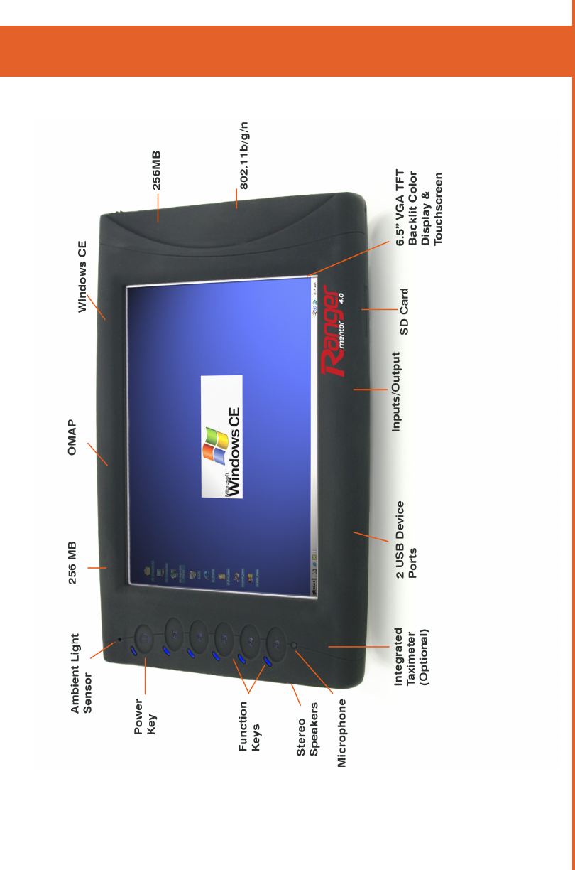
Mentor Ranger® v4.0 is a Windows CE fixed-mount computer
for two-way wireless communication, electronic dispatching, in-
vehicle navigation, and more.
This Ranger Installation guide includes directions for successfully
installing and interfacing a Ranger into a vehicle. Specific wiring
and installation procedures may change from customer to
customer and should be discussed prior to installation. If any
questions remain after reading this guide,please contact Mentor
Engineering, (403) 777-3760 ext. 3, for more information.
inTroduCTion
4.0

8
before you begin
CAUTIONS
a) Carefully read the Installation Guide before installing this
product. If anything is unclear please contact Mentor
Engineering for support.
b) Ensure that the NEGATIVE battery connection is disconnect-
ed before beginning work.
NOTE: Some components may lose short-term memory (i.e.
engine or transmission adaptive parameters, and radio pre-
sets) after a protracted time without battery power.
c) Ranger should be serviced by qualified, trained personnel
only. Attempting to remove the cover or disassemble the
device could expose you to dangerous high voltage points.
d) Only use a damp cloth for cleaning. Never use any type of
liquid/aerosol cleaner or any type of organic solvent to clean
this product.
e) Do not attempt to install or operate a damaged device. If the
unit has been exposed to excessive amounts of water; shows
evidence of physical damage; or is not operating properly;
unplug it from the power source and contact qualified service
personnel.
f) Use of thread-locking compounds such as Loctite may cause
serious damage to plastic enclosures. Many thread-locking
compounds are not compatible with thermoplastics and can
lead to stress cracking. This will require the unit to be re-
turned to replace the ABS enclosures.
ENSURE THAT YOU HAVE ALL OF THE ITEMS LISTED IN
THE PARTS LIST
9
ranger overview
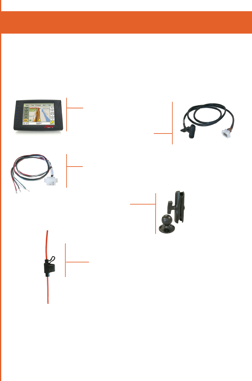
10
Please verify that you have everything that you need to
complete the Ranger installation. NOTE: Not all parts
are provided by Mentor.
• Ranger
• Ranger Interface Cable
4-CAS-CGRDMMLX18-31
• Ranger Power Pigtail
• Ranger Mount
• In-line Cable Fuse(s)
parTs lisT
SUPPLIED
11
SUPPLIED (OPTIONAL)
• Emergency switch
NOT SUPPLIED
• Zip Ties
• Glued Heat Shrink
• Tools as Required
• Grommets
• Loom
• Fasteners
parTs lisT

12
MounTing loCaTions
PLACEMENT
1) Ensure that the driver’s view of the road will not be
impacted.
2) Ensure that the equipment will not be in the path of any
active airbags.
3) Ensure that the driver will still have access to all controls on
the dash.
4) Ensure that the driver has a clear view of the terminal from
the seated driving position.
5) Ensure that the terminal is within easy reach of the driver
from the seated driving position.
6) Ensure that the mounting location is a solid surface.
Locations that allow even small amounts of initial movement
will loosen over time.
7) Before drilling any holes or using screws, check for vehicle
wiring under the carpet or behind the instrument panel which
could be pinched, cut or otherwise damaged.
8) If mounting through the floor, put body sealer over the
underbody projections. Stamped acorn nuts, filled with
sealer, are available at most body shops for this purpose.
This will keep moisture out of the carpet and insulation and
will forestall rust in this area.
9) If mounting under the instrument panel, be sure that there is
no interference with proper operation of the foot controls.
10) Inquire if the vehicle will be cleaned with a high pressure
water wand. If so, ensure that all equipment is installed
somewhere that will be protected from this type of cleaning.
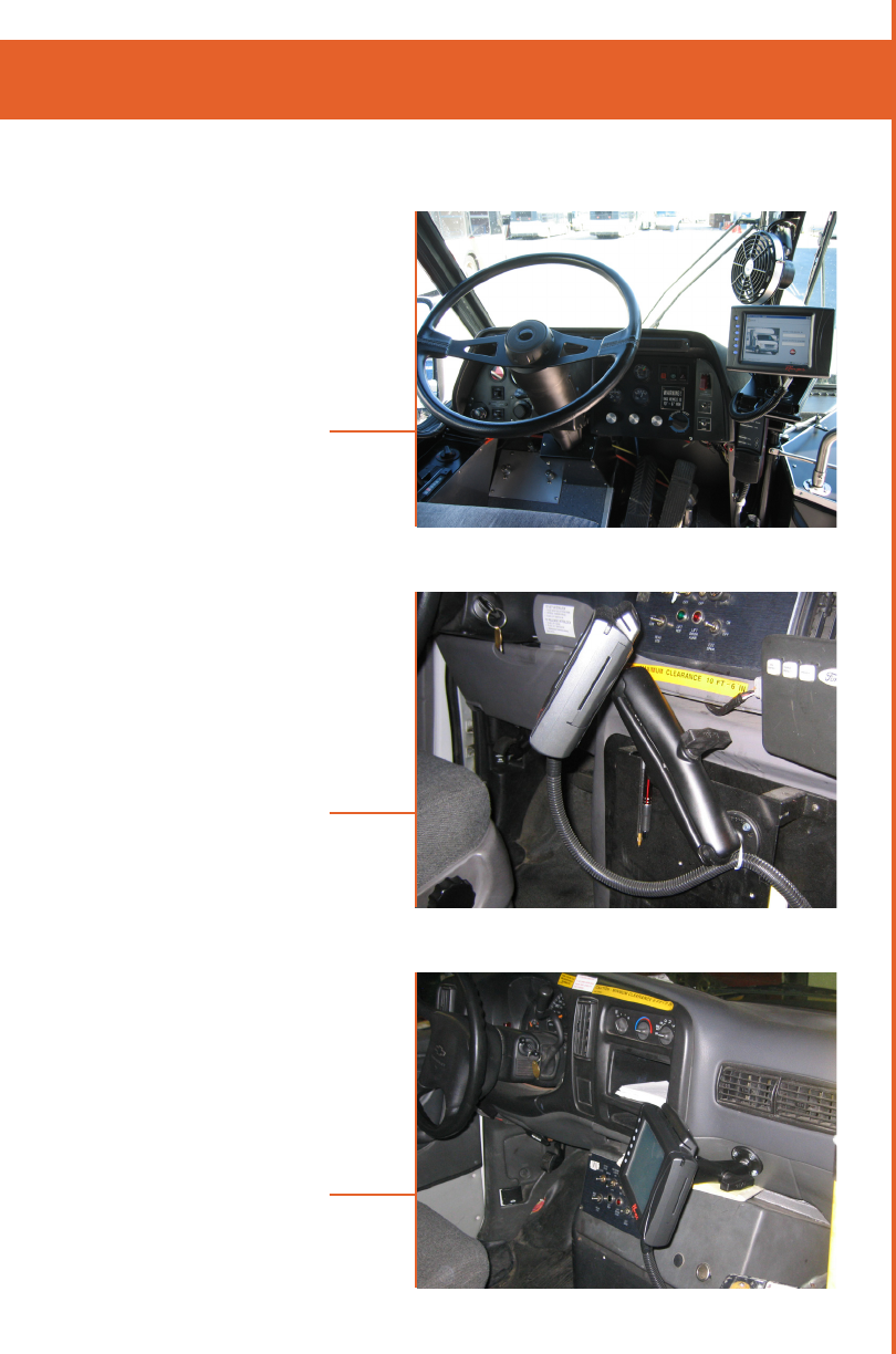
13
ranger MounTing exaMples
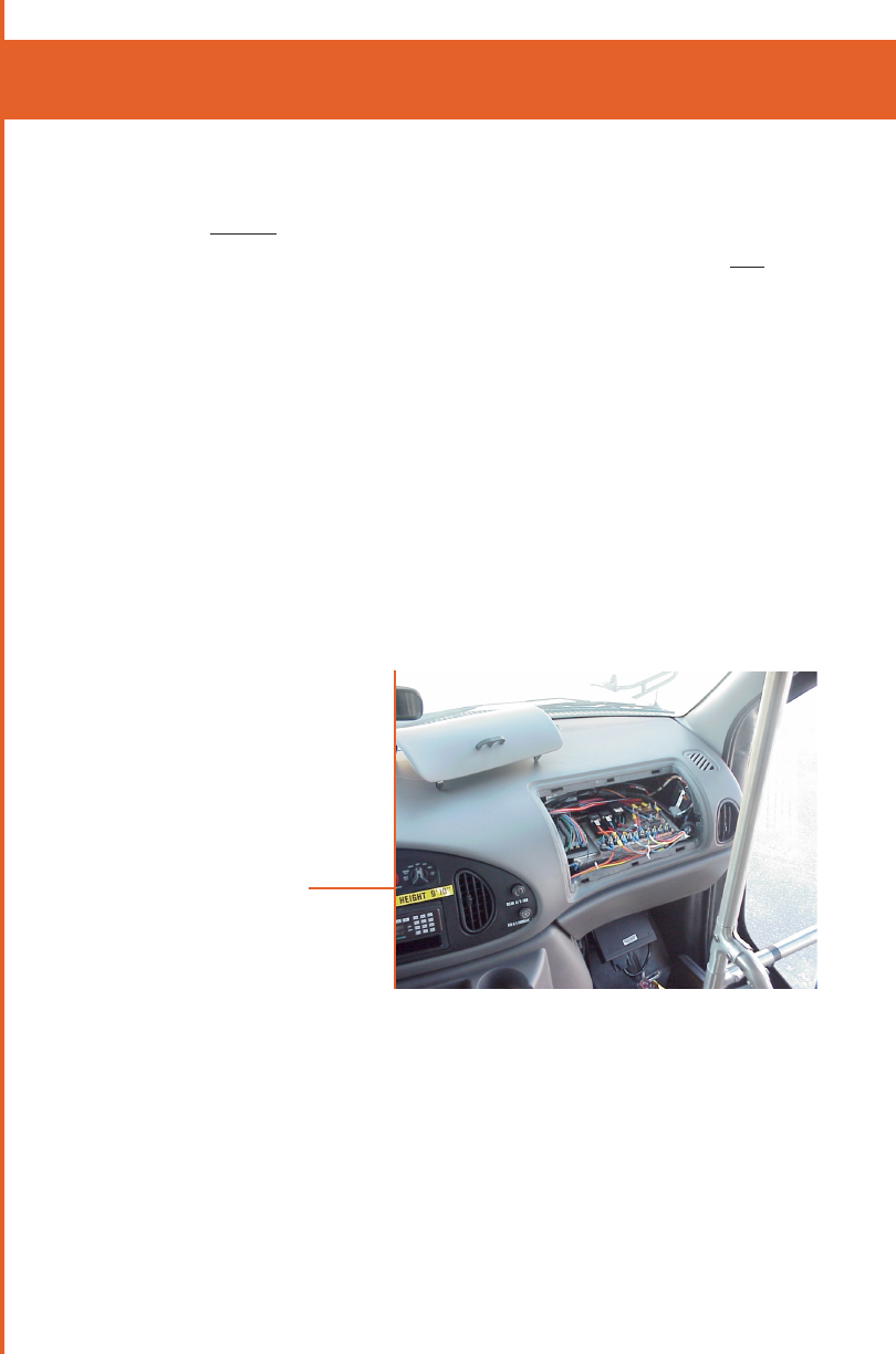
EXAMPLES OF SUITABLE MOUNTING LOCATIONS
Ranger Installed in an
Orion II Bus
Ranger Installed in a
Ford E-Series Cutaway
Ranger Installed in a
Chevrolet 3500 Series Cutaway
Figure 1
Figure 2
Figure 3
14
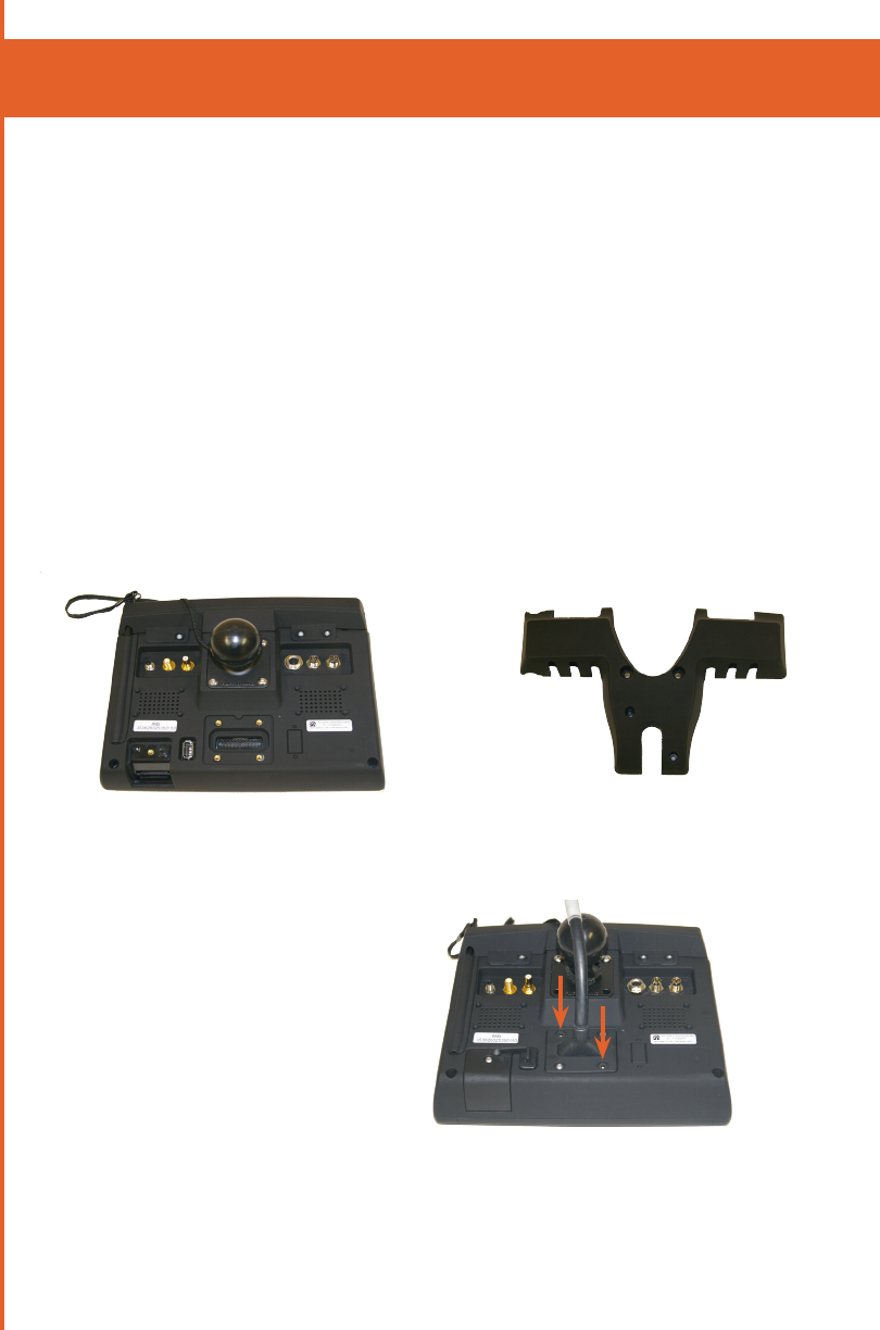
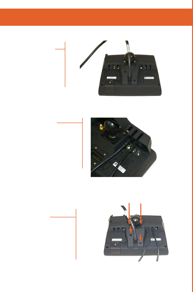
insTalling The ranger Cover plaTe
Ranger Back View
sTep 1
Ranger Back Cover Plate
Connect the Ranger power cable
to the power input as shown. Use
2mm screws and fasten cover. This
requires a 2mm Hex bit.
SUPPLIES REQUIRED TO INSTALL COVER
In order to install the Ranger Cover, the following items
will be used. Most items are included in your shipment of
Ranger equipment:
- Ranger Cover Plate
- 6mm hex head screw (Quantity 2)
- 2mm hex head screw (Quantity 2)
- Hex bit, for 2mm hex head screws
- 5/16” wrench (torque wrench preferred) **
**Not included
15
sTep 2a
insTalling The ranger Cover plaTe
Align the back cover
plate with the Ranger as
shown.
sTep 2b
If there are external cables con-
nected to the Ranger, ensure to
thread the cables through the
holes in the cover.
The cables must be threaded
in such a way that they are
not pinched by the cover when
fastened to the Ranger.
sTep 3
Secure the cover to the
Ranger with the screws
provided. This will require
6mm and 2mm hex head
screws (2 of each).

16
Torque Settings
There are a number of items that may need to be installed to a spe-
cific torque level. This includes the Main Cable Cover, Mounting Ball,
RF Cable Cover and antennas. The following Table lists the recom-
mended torque settings for installing these items. Over and under
torquing can lead to product damage and/or failure.
We recommend using a calibrated torque screwdriver for tightening
all screws. A Huber Suhner SMA torque wrench (74Z-0-0-21) is
recommended for tightening the Antenna cable.
Description Mentor Part Number
Recommended Torque
Oz.In N.cm
Main Cable Cover 3-ENC-RNGRP226-XX 80-90 55-65
Mounting Ball 6-MNT-RAMCMN3X-XX 80-90 55-65
RF Cable Cover 3-ENCRNGRP301-XX 80-90 55-65
R-SMA Antenna Cable 6-ANT-XXXXXXXX-XX 140 100
insTalling The ranger Cover plaTe
17
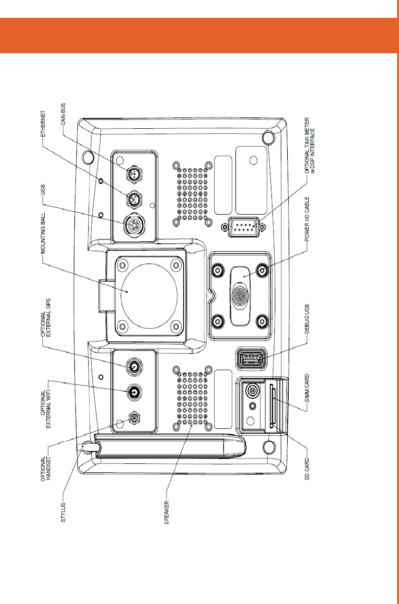
wiring - ranger baCk view
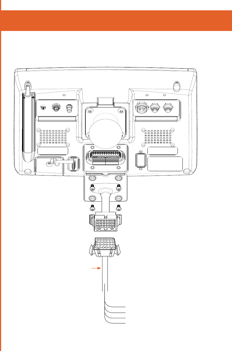
18
4-CAS-PIGTVEHCXX-XX
Green (Ignition Sense, 12/24V, 2A fuse) 6
White (Odometer - typically not used) 7
Red (Vin, 12/24V, 3A fuse) 8
Black (Ground) 16
REQUIRED
wiring - ranger baCk view

19
ConneCTion poinTs
1) SPLICING
T-Taps are not a suitable form of splicing into existing
cabling. All splices must be soldered and glued. Heat
shrink must be used for protection.
2) POWER
Power connections should be made directly to the bat-
tery and fused as close to the battery as possible. Avoid
using a cigarette lighter or “Power Point” receptacles
as power sources. Mentor does not recommend wir-
ing power directly to a vehicle kill switch because the
Ranger will not power down correctly. Appropriate fuses
are provided with the installation equipment.
3) GROUND
The ground point should be that point where the (-)
terminal from the battery is connected to the body. This
connection to the battery is typically a 6 or 8 AWG black
wire connected to the wheelhouse or radiator support.
Do not fuse the ground lead. If the ground-side fuse were
to open, the entire supply current would be conducted
by an alternate current return path, which may cause
the feed line to overheat possibly resulting in damage.
4) SWITCHED IGNITION POWER
It is important to utilize an unused ignition point. Con-
necting to an ignition point that is currently being used
to switch other devices can cause improper operation of
those devices.
There are two methods for interfacing to the vehicle igni-
tion. If neither of these options are possible, then contact
your Mentor project manager and alternate ignition op-
tions can be discussed and approved.
20
It is highly preferable to find an ignition source that goes high only
when the engine is actually on. If this source cannot be found, an
ignition source that goes high only when the ignition is in the ON
position is the next recommended source.
a) Auxiliary Electrical Panel (Preferred)
Many bus manufacturers will include an auxiliary electrical
panel for interfacing peripheral devices. Below is an ex-
ample of a common location in buses with a Ford chassis.
One of these terminals will typically be a switched ignition
point. A ring terminal should be used when connecting to
this type of ignition interface point. Ask the local mainte-
nance personnel if you need assistance to find this panel.
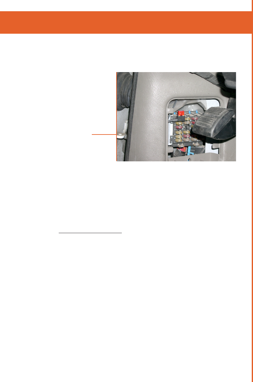
b) Fuse Panel
An unused ignition activated position in the fuse panel is
another option. This installation requires an Add-A-Circuit
fuse holder as pictured below. It is not acceptable to use a
“fuse sleeve”
Example of an Auxiliary
Electrical Panel on a
Ford Van
Figure 6
ConneCTion poinTs
21
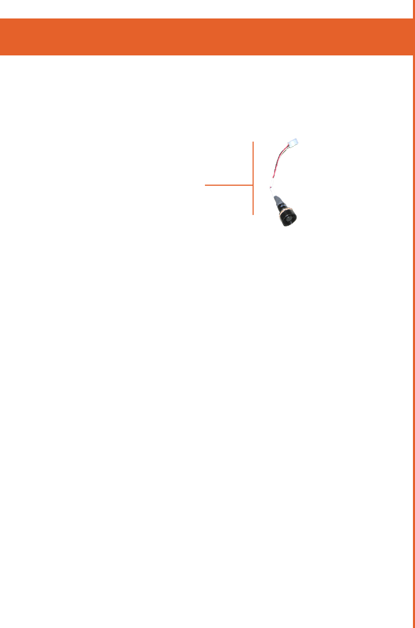
5) VSS (VEHICLE SPEED SENSOR FOR ODOMETER PULSES)
Many vehicles have a VSS point which provides a pulse
train from the transmission. Vehicles that do not have a
VSS point with adequate signal characteristics will require
the installation of a transducer. It is the responsibility of the
installer and customer to locate a VSS point or determine
the appropriate location for a transducer. Your Mentor
Systems Engineer may be able to assist in locating suitable
VSS point. He/She can also provide information on the type
of signal that is required for accurate odometer tracking.
ConneCTion poinTs
Add-A-Circuit Installation
Figure 7
22
ConneCTion poinTs
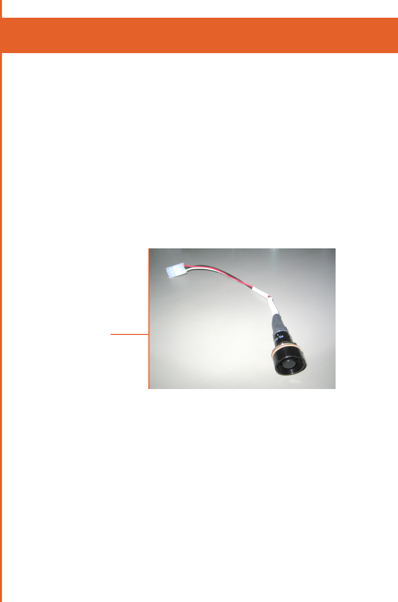
6) EMERGENCY SWITCH (OPTIONAL)
The emergency switch is usually installed somewhere that
would allow for covert operation. This location needs to
be chosen by the customer prior to the start of installa-
tion. Mentor will provide a switch if one is required. It is
sometimes possible to use an existing switch already on the
vehicle. Ranger 4.0 requires a normally closed momentary
push button switch with one side connected to the blue
wire (or the wire corresponding to Pin 14 ) on the Ranger
Power Pigtail input/output cable (Part Number 4-CAS-PIGT-
VEHC24-45_R05).
Emergency Switch
Figure 8
The emergency switch is typically installed on the lower left
side of the driver seat.
Always ensure that the connector on the emergency switch
pigtail is strain reliefed off the floor to prevent shorts if water
enters the connector.

23
Cabling
1) ROUTING
a) Use caution when routing wires between the passenger
and engine compartments to avoid chafing or pinching
the wires. Use grommets over any exposed sharp edges
and strain reliefs to keep wires in place. Seal all holes to
prevent moisture intrusion.
b) Route and secure all under-hood wiring away from mechan-
ical hazards such as exhaust manifolds and moving parts.
c) Maintain as great a distance as possible between mobile
radio power leads and the vehicle’s electronic modules
and wiring. Avoid running power leads in parallel with
vehicle wiring over long distances.
d) If cabling is routed under the instrument panel, be sure
that there is no interference with proper operation of the
foot controls.
2) STRAIN RELIEF
Ensure that there is no strain exerted on cable connectors where
they enter the unit. Avoid placing the unit in a position where
the cable connectors entering the back of the unit are under
pressure or strain of any kind. Ensure the power cable is fully
inserted before replacing the cable cover. In the event of undue
stress or strain on installed cables and connectors, permanent
damage may occur imparing the connections. This may result
in intermittent or complete loss of communication and or power.
Always include strain relief every 2-3 feet on long cable runs.
As the Ranger can be tilted and rotated freely by the driver/user,
cabling should be installed such that moving/adjusting the position
of the unit does not exert any significant stress on the cables.
24
3) LABELING
It is important to always label cabling at connection points.
This simplifies maintenance in the future. Using cables with
consistent coloring will also make maintenance easier.
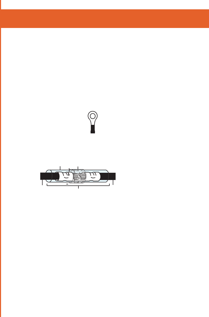
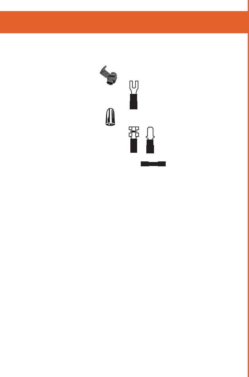
4) CONNECTION TYPES
Acceptable Connection Types
a) Ring Terminals
b) Butt Splices with Self Contained Solder
and Shrink Tubing
c) Soldered Connections with Shrink Tubing
Cabling
1
2
3
4
3
1. Solder Sleeve
2. Crimp Splice (shown crimped)
3. Wire
4. Shrink Tubing
25
Unacceptable Connection Types
a) T-Taps
b) Spade Terminals
c) Marrettes
d) Blade Connectors
e) Standard Butt Splices
5) WIRE TYPES
The following are the minimum specifications for hook-up
wire that should be used during the installation process:
a) Ranger Power and Ground
300V, 105°C PVC, 18AWG stranded
b) Ignition
300V, 105°C PVC, 22AWG stranded
c) Odometer Interface
300V, 105°C PVC, 22AWG stranded
d) Ranger Inputs (i.e. Emergency Input, etc.)
300V, 105°C PVC, 22AWG stranded
6) ELECTRICAL MEASUREMENTS
Always ensure that there is adequate voltage at the point
where Ranger is being powered. Compare this voltage to the
voltage at the battery. The two voltages should be almost the
same or a different power point should be chosen closer to
the battery.
Cabling

26
anTennas
1) INTERNAL ANTENNAS
Ranger 4.0 contains celullar, WIFI, Bluetooth and GPS antennas.
Cellular, WIFI and Bluetooth antennas are capable of transmitting.
Ranger should be installed and operated with a minimum distance of
20 cm (8”) between the radiator and the operator.
The orientation and mounting location of Ranger4.0 can have an
effect on antenna performace.
To optimize GPS performace, mount the Ranger vertically with a
clear view of the sky.
2) EXTERNAL ANTENNAS
If desired, external WIFI and/or GPS antennas can be used with
Ranger 4.0
Specific antenna selection depends on the individual system setup.
Contact Mentor Engineering for assistance in selecting an appropriate
antenna.
Use short lengths of low loss cabling whenever possilbe. WIFI
performace is especailly susceptible to cable losses.
Some importance features to consider are:
Compact construction,
Durability
Weatherproofing
Temperature stability
Mode of Installation

27
Groundplane style antennas are ideally mounted on the centre of a
metal vehicle roof.
Glass mount antennas should be mounted away from metal objects.
When using an adhesive antenna, it is extremely important to make
sure that the surface of the mounting location has been thoroughly
cleaned. Use Isopropyl alcohol to clean the surface just before
securing the adhesive pad.
3) CABLE ROUTING
The antenna cabling has a minimum inside bend radius of 2”. Bend-
ing the cable tighter will cause degradation in antenna performance.
Avoid routing the antenna cable in parallel with the vehicle wiring
over long distances.
Do not coil excess antenna cable slack.
anTennas
Antenna Routing
Figure 7

28
CONNECTORS
• R- SMA - The reverse SMA connector is used for WIFI and
requires a 1N-M torque wrench to properly secure
• QMA - The QMA connector is used for GPS and is a snap
on version of the SMA connector
anTennas

29
ranger speCs 7-rngr-04x
GENERAL DESCRIPTION
Mentor Ranger® v4 is a water resistant1,2 WinCE de-
vice that is equipped with color Touchscreen display,
Compact Flash, smart card/magnetic card readers and
USB host/device port. Application software can be
custom-designed making it adaptable to a wide variety
of applications. It has an optional internal wireless
modem for HSPDA or EVDO networks. Internal GPS
allows Ranger to be used for vehicle navigation, AVL
(Automatic Vehicle Location) and/or Computer Aided
Dispatch systems for fleet applications.
STANDARD FEATURES
• 256MB of Flash
• 256MB of DDR SDRAM
• 2 USB Device Ports8
• Bluetooth 2.1
• WIFI 802.11b/g/n
• CANBUS J1939
• J1708
• Built in Odometer Signal Conditioner
• 4 Digital Input / Open Drain Output with soft
ware selectable pull up or pull down
• 6 Button Capacitive Touch Keypad
• 3W Stereo Speakers
• 6.5” TFT Color Display with Touchscreen
• External SD Card Socket
• Covert Microphone
• 2 RS-232 Com Ports
• Tactile Wear Resistant Coating
• Internal 50 Channel GPS

30
ranger speCs 7-rngr-04x
COMPLIANCE AND TESTING
• FCC Class B Part 15
• IEC 60950 3rd Edition (2000)
• ISO 7637-1 Load Dump Transient
• MIL STD 810F: General Vibration
• MIL STD 810F: Shock
• IP54: Environmental, Dust and Water exposure 7
OPTIONAL FEATURES
• Taximeter
• ISO 7811 Magnetic card reader/ISO 7816 Smart Card
Reader (combined module)
• Internal SD Card Socket (4GB max)
• Internal Wireless Data Modems
(HSDPA or EVDO or DSP Radio)3
• Handset and/or Handsfree Voice Calls
KEY SPECIFICATIONS
• Supply Voltage
Typical 12 V
Min 6 V
Max 32 V
• Current Consumption
Input Voltage
(V)
Current Draw (mA)
Standby Idle4Typical5
9 68 360 965
13.8 50 250 645
24 39 160 405
Maximum6 3.0 A

31
ranger speCs 7-rngr-02x
• Operating Temperature
Min -30o C Max 65o C
• Storage Temperature
Min -30o C Max 70o C
• Size
8.25” x 2.0” x 5.75”
210mm x 57mm x 146 mm
• Weight
2.0 lbs / 0.9 kg
• 5% - 95% relative humidity non-condensing
Foot Notes
1) Ranger is designed to be splash resistant. It’s not designed to be immersed in
water.
2) Ranger may not be water resistant when some of the options are specified.
3) DSP Radio and Wireless Modem options cannot be specified at the same
time.
4) When diisplay is off, the unit is in idle without modem options
5) Unit Idle with full backlight with GPS, Wifi and Bluetooth. No modem
options
6) This is an absolute maximum which includes an installed
modem and all peripheral devices. Actual current draw will depend on system
design.
7) Unit is IP54 rated for water without Mag swipe, or Taximeter Options or DSP
modem.

32
ranger speCs 7-rngr-02x
8) USB 2.0 High Speed; One port is for maintenance only.
NOTE: Mentor Engineering Inc. reserves the right to change
circuitry and specifications without notice at any time.
Please ensure you have the most recent revision of this
document.
NOTE: Operation at Temperatures outside the ranges is not
recommended.
NOTE: Only use Mentor Engineering approved cables for
installation purposes. Refer to cable section of
the Hardware Installation Manual for additional
information.

33
appendix a - ConforMiTy
1) FCC CLASS B PART 15
This device complies with Part 15 of FCC Rules. Opera-
tion is subject to the following two conditions:
1. This device may not cause harmful interference
2. This device must accept any interferenc
recceived, including interference that may cause
undesired operation.
INDUSTRY CANADA STATEMENT
Under Industry Canada regulations, this radio transmitter may
only operate using an antenna of a type and maximum (or
lesser) gain approved for the transmitter by Industry Canada. To
reduce potential radio interference to other users, the antenna
type and its gain should be so chosen that the equivalent isotro-
pically radiated power (e.i.r.p.) is not more than that necessary
for successful communication.
This device complies with Industry Canada licence-exempt RSS
standard(s). Operation is subject to the following two condi-
tions:
(1) this device may not cause interference, and
(2) this device must accept any interference, including ...
interference that may cause undesired operation of the
device.
Conformément à la réglementation d’Industrie Canada, le
présent émetteur radio peut fonctionner avec une antenne
d’un type et d’un gain maximal (ou inférieur) approuvé pour
l’émetteur par Industrie Canada. Dans le but de réduire les ris-
ques de brouillage radioélectrique à l’intention des autres utilisa-
teurs, il faut choisir le type d’antenne et son gain de sorte que
la puissance isotrope rayonnée équivalente (p.i.r.e.) ne dépasse
pas l’intensité nécessaire à l’établissement d’une communica-

34
appendix a - ConforMiTy
tion satisfaisante.
Le présent appareil est conforme aux CNR d’Industrie Canada ap-
plicables aux appareils radio exempts de licence. L’exploitation est
autorisée aux deux conditions suivantes :
(1) l’appareil ne doit pas produire de brouillage, et
(2) l’utilisateur de l’appareil doit accepter tout brouillage ra
dioélectrique subi, même si le brouillage est susceptible
d’en compromettre le fonctionnement.
NOTE: This equipment has been tested and found to
comply with the limits for a Class B digital device, pursuant
to Part 15 of the FCC Rules. These limits are designed to
provide reasonable protection against harmful interference
when the equipment is operated in a commercial environ-
ment. This equipment generates, uses, and can radiate
radio frequency energy and, if not installed and used in
accordance with the instruction manual, may cause harm-
ful interference to radio communications. However, there is
no guarantee that interference will not occur in a particulat
installation.
If this equipment does cause harmful interference to radio
or television reception, which can be determined by turn-
ing the equipment off and on, the user is encouraged to try
to correct the interference by one or more of the following
measues:
- Reorient or relocate the receiving antenna.
- Increase the separation between the equipment and
receiver.

35
- Connect the equipment into an outlet on a circuit
different from that to which the receiver is connected.
- Consult the dealer or an experienced radio/TV
technician for help.
2) IEC 60950 3RD EDITION (2000) SAFETY OF INFORMATION
TECHNOLOGY EQUIPMENT
3) ISO 7637-1 LOAD DUMP TRANSIENT
Designed for ISO 7637-1 Load Dump Transient
4) MIL STD 810F: GENERAL VIBRATION
Tested to MIL-STD-810F Vibration Test Method 514.5 Procedure
I: General Vibration, Category 20 Ground Vehicles.
4.1) Highway Vehicle Endurance Testing
Each axis was exposed to 1 hour of vibration according to Figure
514.5C-1 U.S. Highway Truck Vibration Exposure Levels. This is
an accelerated fatigue test meant to test the unit’s life cycle. The
unit was functionally tested before and after the test.
5) MIL STD 810F: SHOCK TEST
Tested to MIL-STD-810F Shock Test Method 516.5 Procedure I:
Functional Shock. Functional Shock was performed on the verti-
cal, transverse, and longitudinal axes with a pulse of 40gs. The
tests were performed to ensure the unit stays intact during vehicle
operation.
6) IEC 60529 - IP54
Tested to IEC 60529 IP54 for protection against ingress of water
with harmful effects splashing. Unit must not be equipped with
magnetic card reader or taximeter.
appendix a - ConforMiTy

36
appendix b - rf radiaTion speCs
RF EXPOSURE
This equipment complies with FCC radiation exposure limits
set forth for an uncontrolled environment. This equipment
should be installed and operated with minimum distance of 20
cm between the radiator and your body.
This transmitter must not be co-located or operating in con-
junction with any other antenna or transmitter.

37
appendix b - rf radiaTion speCs appendix C - approvals
1) CDMA/EVDO - VOICE/DATA NETWORK CERTIFICATIONS
FCC ID: RZ3RAN45728
IC ID:2234A-RAN45728
Approvals: FCC, IC
2) GSM/HSDPA
FCC ID RZ3RAN48790
IC ID 2234A-RAN48790
Approvals: FCC, IC, PTCRB
3) WIFI/BLUETOOTH ONLY - NO CELLULAR MODEM
Contains Transmitter Module FCC ID: N7NMC8790
FCC ID RZ3RAN49110
IC ID 2234A-RAN49110