Trendnet Industrial Single Board Computer Hs 6038 Users Manual Version 1.0 April 2004
HS-6038 to the manual 3e268f32-6135-4433-acd1-40a6d607283e
2015-02-02
: Trendnet Trendnet-Industrial-Single-Board-Computer-Hs-6038-Users-Manual-450065 trendnet-industrial-single-board-computer-hs-6038-users-manual-450065 trendnet pdf
Open the PDF directly: View PDF ![]() .
.
Page Count: 86
HS-6038
Socket 370 133MHz FSB
Industrial Single Board Computer
•Full-size•All-in-One•CompactFlash•
•133MHz FSB•CRT•Dual LAN•Audio•
•ATA/33/66/100•RS-232/422/485•PC/104•
•IrDA•USB•DOC•WDT•H/W Monitor•
•PICMG Bus Industrial Single Board Computer•

Copyright Disclaimers
The accuracy of contents in this manual has passed thorough checking and review
before publishing. BOSER Technology Co., Ltd., the manufacturer and publisher, is
not liable for any infringements of patents or other rights resulting from its use. The
manufacturer will not be responsible for any direct, indirect, special, incidental
or consequential damages arising from the use of this product or
documentation, even if advised of the possibility of such damage(s).
This manual is copyrighted and BOSER Technology Co., Ltd. reserves all
documentation rights. Unauthorized reproduction, transmission, translation,
and storage of any form and means (i.e., electronic, mechanical, photocopying,
recording) of this document, in whole or partly, is prohibited, unless granted
permission by BOSER Technology Co., Ltd.
BOSER Technology Co., Ltd. reserves the right to change or improve the
contents of this document without due notice. BOSER Technology Co., Ltd.
assumes no responsibility for any errors or omissions that may appear in this
manual, nor does it make any commitment to update the information contained
herein.
T
T
Tr
r
ra
a
ad
d
de
e
em
m
ma
a
ar
r
rk
k
ks
s
s
BOSER is a registered trademark of BOSER Technology Co., Ltd.
ISB is a registered trademark of BOSER Technology Co., Ltd.
Intel is a registered trademark of Intel Corporation.
AMI is a registered trademark of American Megatrends, Inc.
Award is a registered trademark of Award Software, Inc.
All other trademarks, products and or product names mentioned herein are
mentioned for identification purposes only, and may be trademarks and/or
registered trademarks of their respective companies or owners.
© Copyright 2004 BOSER Technology Co., Ltd.
All Rights Reserved.
Version 1.0, May 06, 2004
Table of Contents
Chapter 1 General Description…………………...1
1.1 Major Features.................................................................. 2
1.2 Specifications ................................................................... 3
1.3 Board Dimensions............................................................ 4
Chapter 2 Unpacking……………………………..5
2.1 Opening the Delivery Package........................................ 5
2.2 Inspection.......................................................................... 5
Chapter 3 Hardware Installation………………...7
3.1 Before Installation ............................................................ 7
3.2 Board Layout .................................................................... 8
3.3 Jumper List ....................................................................... 9
3.4 Connector List .................................................................. 9
3.5 Configuring the CPU ...................................................... 10
3.6 System Memory .............................................................. 10
3.7 VGA Controller ............................................................... 10
3.8 IDE Drive Connector ...................................................... 11
3.9 Floppy Disk Drive Connector ........................................ 12
3.10 Serial Port Connectors .................................................. 12
3.11 Parallel Connector.......................................................... 13
3.12 Ethernet Connector........................................................ 14
3.13 IrDA Connector............................................................... 14
3.14 USB Connector............................................................... 15
3.15 CMOS Data Clear............................................................ 15
3.16 Power and Fan Connectors........................................... 16
3.17 Keyboard/Mouse Connectors ....................................... 17
3.18 System Front Panel Connectors................................... 17
3.19 External Speaker ............................................................ 18
3.20 Thermal Input Connectors............................................. 18
3.21 Audio Connectors .......................................................... 19
3.22 SMI Signal Input Switch................................................. 19
3.23 Watchdog Timer ............................................................. 20
3.24 CompactFlash Connector........................................... 21
3.25 PC/104 Connectors ........................................................ 22
3.26 DiskOnChip Address Setting ..................................... 25
Chapter 4 AMI BIOS Setup……………………..27
4.1 Starting Setup ................................................................. 27
4.2 Using Setup..................................................................... 28
4.3 Main Menu ....................................................................... 29
4.4 Standard CMOS Setup ................................................... 30
4.5 Advanced CMOS Setup ................................................. 31
4.6 Advanced Chipset Setup ............................................... 32
4.7 Power Management Setup ............................................ 33
4.8 PCI / Plug and Play Setup.............................................. 34
4.9 Peripheral Setup............................................................. 35
4.10 Hardware Monitor Setup................................................ 36
4.11 Auto-Detect Hard Disks ................................................. 37
4.12 Change Supervisor/User Password ............................. 38
4.13 Auto Configuration with Optimal Settings .................. 39
4.14 Optimal Configuration with Fail Safe Settings............ 40
4.15 Save Settings and Exit................................................... 41
4.16 Exit Without Saving........................................................ 42
Chapter 5 Software Utilities…………………….43
5.1 IDE Driver Installation .................................................... 43
5.2 VGA Driver Installation .................................................. 49
5.3 LAN Driver Installation................................................... 55
5.4 Audio Driver Installation................................................ 74
Safety Instructions
Integrated circuits on computer boards are sensitive to static electricity.
To avoid damaging chips from electrostatic discharge, observe the
following precautions:
Do not remove boards or integrated circuits from their anti-static
packaging until you are ready to install them.
Before handling a board or integrated circuit, touch an unpainted portion
of the system unit chassis for a few seconds. This helps to discharge any
static electricity on your body.
Wear a wrist-grounding strap, available from most electronic component
stores, when handling boards and components. Fasten the ALLIGATOR
clip of the strap to the end of the shielded wire lead from a grounded
object. Please wear and connect the strap before handle the HS-6038 to
ensure harmlessly discharge any static electricity through the strap.
Please use an anti-static pad when putting down any components or
parts or tools outside the computer. You may also use an anti-static bag
instead of the pad. Please inquire from your local supplier for additional
assistance in finding the necessary anti-static gadgets.
NOTE: DO NOT TOUCH THE BOARD OR ANY OTHER SENSITIVE
COMPONENTS WITHOUT ALL NECESSARY ANTI-STATIC
PROTECTION.
1
Chapter 1
General Description
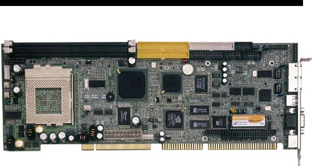
The HS-6038 is a 133MHz FSB Intel® 82815/82801BA chipset-based
board designed for PICMG Bus Celeron™/Coppermine™/Tualatin™
800MHz~1.2GHz CPU compatibility. These features combine and
make the HS-6038 an ideal all-in-one industrial single board computer.
Additional features include an enhanced I/O with CompactFlash, VGA,
dual LAN, audio, and two COM interfaces.
Its onboard ATA/33/66/100 to connected IDE drive interface
architecture allows the HS-6038 to support data transfers of 33, 66 or
100MB/sec. for each IDE drive connection. Designed with the Intel®
82815/82801BA core logic chipset, the board supports all
Celeron™/Coppermine™/Tualatin™ CPU series operating at 800MHz
to 1.2GHz. The 82815 integrated CRT display controller supports up to
1280 x 1024 at 16 color resolution.
A single Flash chip holds the system BIOS, and you can change the
Flash BIOS by the Utility Update. Advanced IrDA port also provides a
faster data transmission. You can also use the DOS version of the
“DiskOnChipTM” socket by issuing commands from the DOS prompt
without the necessity of other software supports up to 288MB. System
memory is also sufficient with the two DIMM sockets that can support
up to 512MB.
2
Additional onboard connectors include an advanced USB and IrDA
ports providing faster data transmission, and a dual RJ-45 connector
for 10/100 Based Ethernet use.
To ensure the reliability in an unmanned or standalone system, the
Watchdog Timer (WDT) onboard HS-6038 is designed with pure
hardware that does not need the arithmetical functions of a real-time
clock chip. If any program causes unexpected halts to the system, the
onboard Watchdog Timer (WDT) will automatically reset the CPU or
generate an interrupt to resolve such condition.
The HS-6038 also has a CompactFlashTM connector that
accommodates standard of memory cards available in the market.
1.1 Major Features
The HS-6038 comes with the following features:
Socket 370 for Intel® Celeron/Coppermine/Tualatin 800MHz
~1.2GHz CPU
Supports 66/100/133MHz FSB
Two DIMM sockets with a max. capacity of 512MB
Intel® 82815/82801BA system chipset
Winbond W83627 super I/O chipset
Intel 82815 CRT display controller
Intel 82559 and ICHII 10/100 Based LAN
AC97 3D audio controller
Two COM, four USB connectors
PC/104 Bus connector
DiskOnChipTM socket supporting memory sizes of up to 288MB
Supports Hardware Monitor
Supports CompactFlashTM card reader (optional)
3
1.2 Specifications
CPU: Socket 370 for Intel Celeron/Coppermine/Tualatin 800MHz
~1.2GHz CPU
Bus Interface: PICMG Bus
Memory: Two DIMM sockets supporting up to 512MB
Chipset: Intel® 82815/82801BA
I/O Chipset: Winbond W83627
CompactFlash: One, IDE interface adapter (optional)
VGA: Intel 82815 supporting CRT display up to 1280 x 1024 at 16 colors
LAN: Intel® 82559 and Intel® ICHII 10/100 Based LAN
Audio: AC97 3D audio controller
IDE: Four IDE disk drives supporting ATA/33/66/100 and with transfer
rates of up to 33/66/100MB/sec.
FDD: Supports up to two floppy disk drives
Parallel: One enhanced bi-directional parallel port supporting
SPP/ECP/EPP
Serial Port: 16C550 UART-compatible RS-232/422/485 x 1 and RS-232
x 1 serial ports with 16-byte FIFO
PC/104: PC/104 connector for 8-bit ISA Bus
IrDA: One TX/RX IrDA header
USB: Four USB connectors
Keyboard/Mouse: PS/2 6-pin Mini DIN
DiskOnChip: DiskOnChip socket supporting memory sizes of up to
288MB
BIOS: AMI PnP Flash BIOS
Watchdog Timer: Software programmable time-out intervals from
1~256 sec.
CMOS: Battery backup
Power Consumption: +5V/7.5A (1GHz CPU), +12V/120mA
Operating Temperature: 0~60°C
Hardware Monitor: Winbond W83627
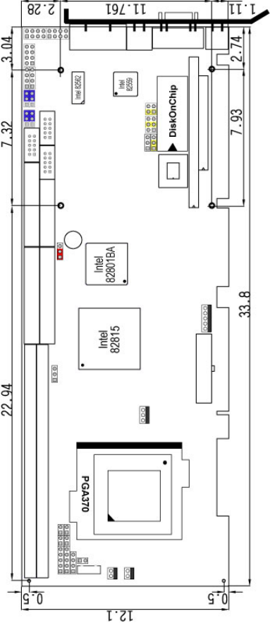
Board Size: 33.8 x 12.1 cm
4
1.3 Board Dimensions

5
Chapter 2
Unpacking
2.1 Opening the Delivery Package
The HS-6038 is packed in an anti-static bag. The board has
components that are easily damaged by static electricity. Do not
remove the anti-static wrapping until proper precautions have been
taken. Safety Instructions in front of this manual describe anti-static
precautions and procedures.
2.2 Inspection
After unpacking the board, place it on a raised surface and carefully
inspect the board for any damage that might have occurred during
shipment. Ground the board and exercise extreme care to prevent
damage to the board from static electricity.
Integrated circuits will sometimes come out of their sockets during
shipment. Examine all integrated circuits, particularly the BIOS,
processor, memory modules, ROM-Disk, and keyboard controller chip
to ensure that they are firmly seated. The HS-6038 delivery package
contains the following items:
HS-6038 Industrial Single Board Computer
ATA/100 IDE flat cable x 2
FDD flat cable x 1
Printer cable with bracket x 1
KB/MS transfer cable x 1
8-pin USB split type cable with bracket x 1
Speaker connector flat cable with bracket x 1
Two RS-232 cable with bracket x 1
5-pin ATX cable x 1
Jumper Bag
Utility CD-ROM
User’s Manual
6
It is recommended that you keep all the parts of the delivery package
intact and store them in a safe/dry place for any unforeseen event
requiring the return shipment of the product. In case you discover any
missing and/or damaged items from the list of items, please contact
your dealer immediately.

7
Chapter 3
Hardware Installation
This chapter provides the information on how to install the hardware
using the HS-6038. This chapter also contains information related to
jumper settings of switch, watchdog timer, and the DiskOnChip
address selection etc.
3.1 Before Installation
After confirming your package contents, you are now ready to install
your hardware. The following are important reminders and steps to
take before you begin with your installation process.
1. Make sure that all jumper settings match their default settings
and CMOS setup correctly. Refer to the sections on this chapter
for the default settings of each jumper.
2. Go through the connections of all external devices and make
sure that they are installed properly and configured correctly
within the CMOS setup. Refer to the sections in this chapter for
the detailed information on the connectors.
3. Keep the manual and diskette in good condition for future
reference and use.
8
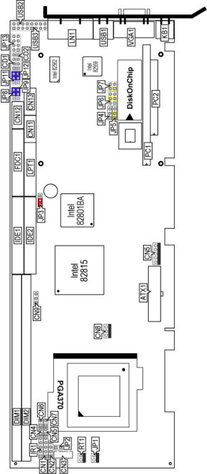
3.2 Board Layout

9
3.3 Jumper List
Jumper Definition Setting
Page
JP2 Host Bus Clock Rate Select: 133MHz FSB Open 10
JP3 Clear CMOS: Normal Operation Short 1-2 15
JP4 LAN2 Enabled/Disabled Select: Enabled Short 1-2 14
JP5 WDT Active Type Setting: System Reset Short 2-3 20
JP6 Short 3-4 25
JP7
DiskOnChip Address Select: 0D000H~
0D1FFH Short 1-2 25
JP8 / JP9 /
JP11 / JP12
COM 2 Use RS-232 or RS-422/485 Select:
RS-232 Short 2-3 12
3.4 Connector List
Connector Definition Page
ATX1 20-pin ATX Power In Connector 16
CD1 CD-ROM Analog Input Connector 19
CD2 Line In Connector 19
CN1 Keylock Connector 17
CN2 Speaker Connector 18
CN3 5-pin Keyboard Connector 17
CN4 HDD LED Connector 17
CN5 SMI Signal Input Connector 19
CN6 2-pin ATX Power On Switch 16
CN7 2-pin Reset Button Connector 17
CN8 Fan Power In Connector 16
CN9 I2C Bus Connector 10
CN10 5-pin ATX Power In Connector 16
CN11 COM 1 Connector (5x2 header) 12
CN12 RS-422/485 Connector (5x2 header) 12
CN13 COM 2 Connector (5x2 header) 12
CF1 CompactFlashTM Connector 21
DIM1/DIM2 168-pin DIMM Sockets 10
FDC1 Floppy Connector 12
IDE1/IDE2 Primary/Secondary IDE Connectors 11
IR1 IrDA Connector 14
JP1 System Sensing Connector 18
JP13 MIC In / Audio Out Connector 19
KB1 PS/2 6-pin Mini DIN KB/MS Connector 17
LAN1 Dual RJ-45 Connector 14
LPT1 Parallel Connector 13
…More on next page…
10
Connector Definition Page
PC1 / PC2 PC/104 Bus 64-pin/40-pin Connectors 22
USB1 External USB Connector 15
USB2/USB3 Internal USB Connectors 15
RT1/RT2 Power Sensing Connectors 18
VGA1 15-pin VGA Connector 10
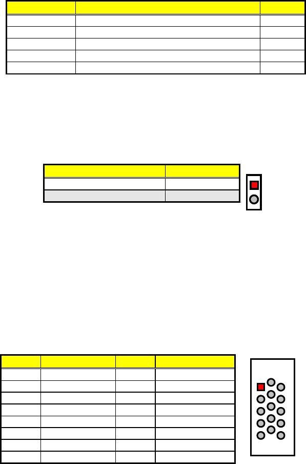
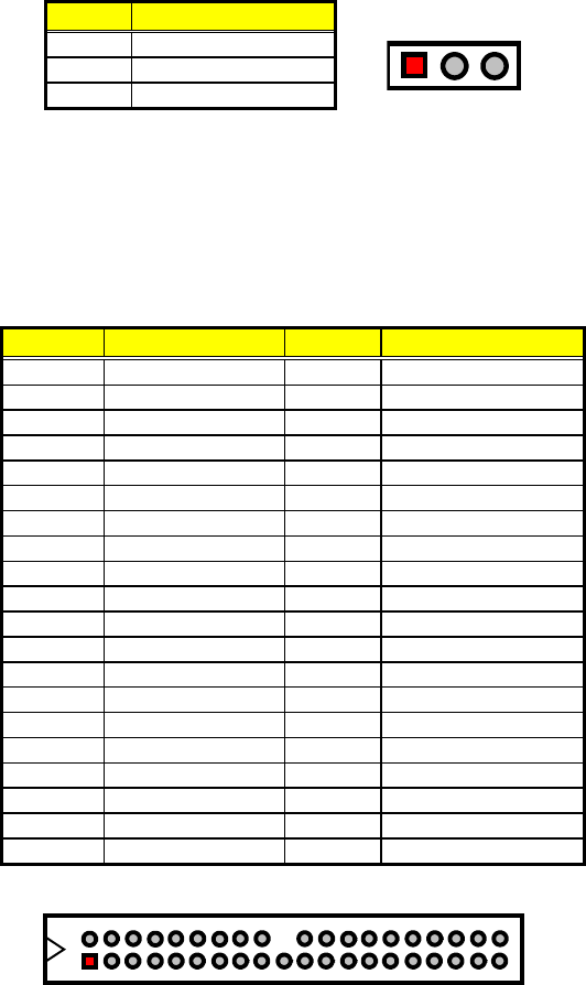
3.5 Configuring the CPU
JP2 is used to set the Host Bus Clock Rate. The setting of internal Host
Bus Clock Rate is for defining the operating clock base rate of the
internal bus of core logic.
JP2: Host Bus Clock Rate Select
Description Setting
66/100MHz FSB Short
133MHz FSB (default) Open
1
2
3.6 System Memory
The HS-6038 provides two 168-pin DIMM sockets at locations DIM1
and DIM2. The maximum capacity of the onboard memory is 512MB.
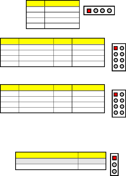
3.7 VGA Controller
The HS-6038 provides one connection for VGA device. VGA1 offers a
single standard 15-pin CRT connector.
VGA1: 15-pin CRT Connector
PIN Description PIN Description
1 Red 2 Green
3 Blue 4 VCC
5 GND 6 GND
7 GND 8 GND
9 VCC 10 GND
11 VCC 12 DDCDA
13 HSYNC 14 VSYNC
15 DDCCL
1
6
10
11
515
An Inter-IC connector CN9, also offers the flexibility of installing an I2C
digital signal-based device.
11
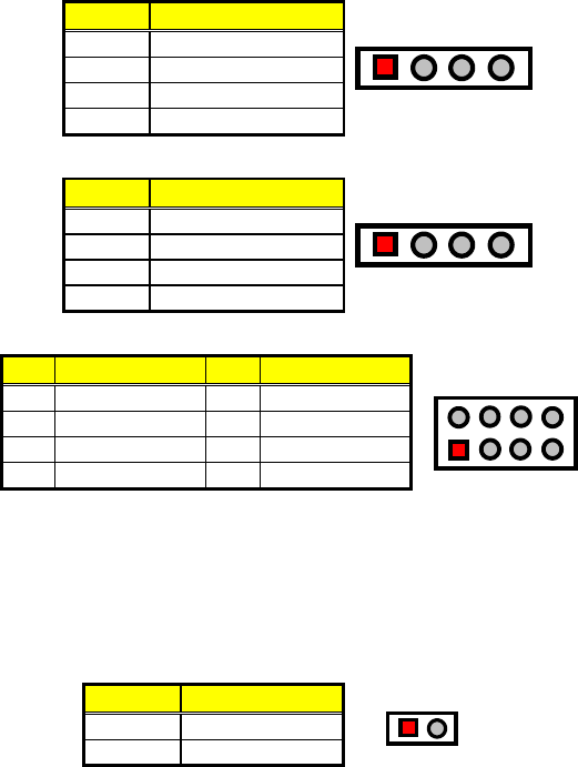
CN9: I2C Bus Connector
PIN Description
1 SMBDATA
2 SMBCLK
3 GND
123
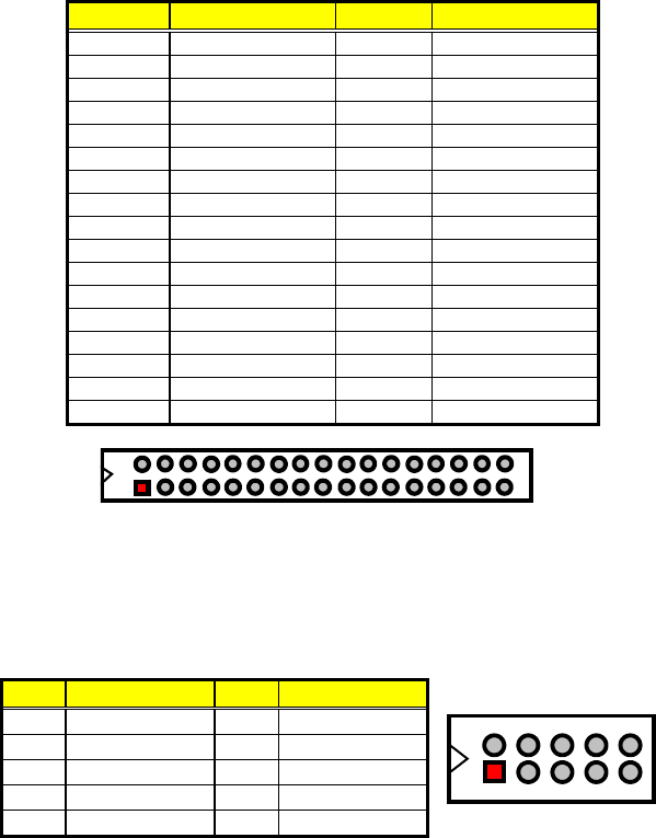
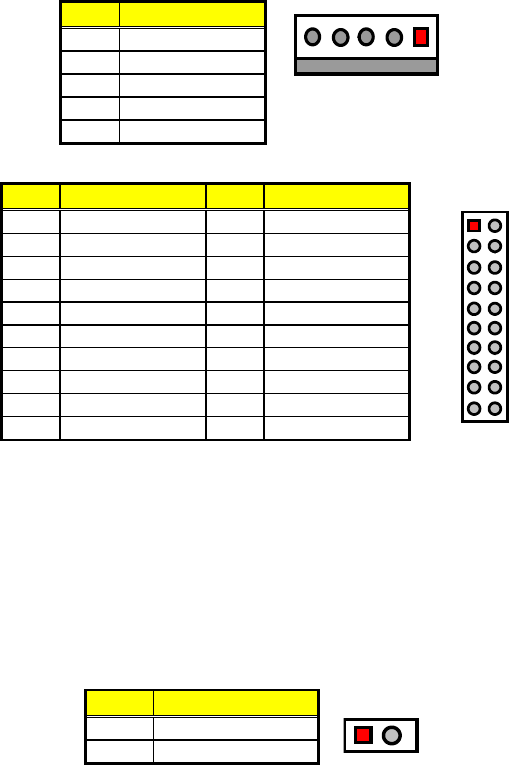
3.8 IDE Drive Connector
IDE1/IDE2 are standard 40-pin connector daisy-chain driver
connectors serving the PCI E-IDE drive provisions onboard the
HS-6038. A maximum of four IDE drives can be connected to the
HS-6038 via IDE1/IDE2.
IDE1/IDE2: Primary/Secondary IDE Connectors
PIN Description PIN Description
1 RESET 2 GND
3 DATA 7 4 DATA 8
5 DATA 6 6 DATA 9
7 DATA 5 8 DATA 10
9 DATA 4 10 DATA 11
11 DATA 3 12 DATA 12
13 DATA 2 14 DATA 13
15 DATA 1 16 DATA 14
17 DATA 0 18 DATA 15
19 GND 20 N/C
21 PDREQ 22 GND
23 PDIOW# 24 GND
25 PDIOR# 26 GND
27 PIORDY 28 GND
29 RPDACK- 30 GND
31 IRQ14 32 N/C
33 RPDA1- 34 PATA66DET
35 RPDA0- 36 RPDA2-
37 RPCS1- 38 RPCS3-
39 HDD ACTIVE 40 GND
1
240
39
3 5 7 9 17 19 21 23 25 27 29 31 33
11 13 15 35 37
46810 18 20 22 24 26 28 30 32 34
12 14 16 36 38
12
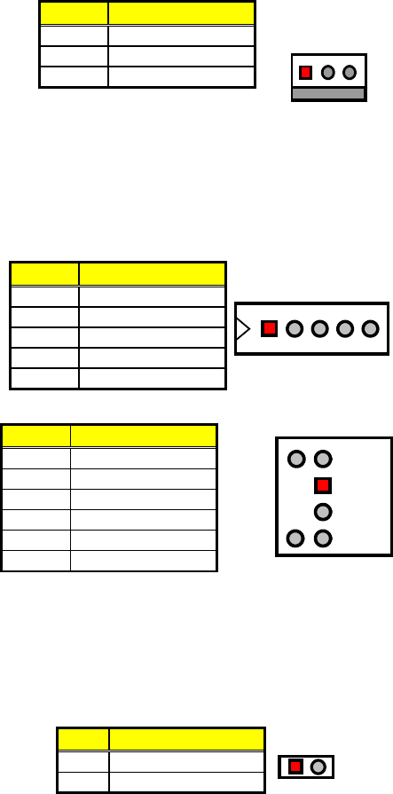
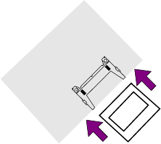
3.9 Floppy Disk Drive Connector
The HS-6038 uses a standard 34-pin header connector, FDC1, for
floppy disk drive connection. A total of two floppy drives may be
connected to FDC1 at any given time.
FDC1: Floppy Connector
PIN Description PIN Description
1 GND 2 RWC-
3 GND 4 N/C
5 GND 6 DS1-
7 GND 8 Index#
9 GND 10 Motor Enable A#
11 GND 12 Drive Select B#
13 GND 14 Drive Select A#
15 GND 16 Motor Enable B#
17 GND 18 Direction#
19 GND 20 Step#
21 GND 22 WD-
23 GND 24 WE-
25 GND 26 Track 0#
27 GND 28 WP-
29 N/C 30 RDATA-
31 GND 32 HEAD-
33 N/C 34 DSKCHG-
34
33
1
2
u
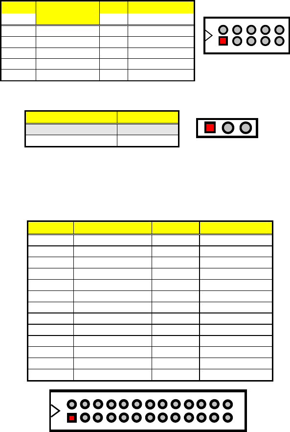
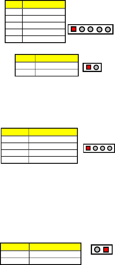
3.10 Serial Port Connectors
The HS-6038 offers one NS16C550 compatible UARTs with
Read/Receive 16-byte FIFO serial ports.
CN11, CN13: COM1/COM2 Connectors (5x2 header)
PIN Description
PIN Description
1 DCD 2 DSR
3 RXD 4 RTX
5 TXD 6 CTX
7 DTR 8 RI
9 GND 10 N/C
246810
13579
13
CN12: RS-422/485 Connector (5x2 header)
PIN Descriptio
n
PIN Description
1 TX- 2 TX+
3 RX+ 4 RX-
5 GND 6 RTS-
7 RTS+ 8 CTS+
9 CTS- 10 N/C
246810
13579
TX+
RX-
RTS-
N/C
CTS+
TX-
RX+
GND
CTS-
RTS+
JP8/JP9/JP11/JP12: COM2 Use RS-232 or RS-422/485 Select
Options Settings
RS-232 (default) Short 2-3
RS-422/485 Short 1-2
13
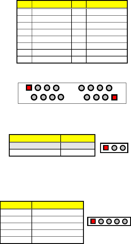
3.11 Parallel Connector
LPT1 is a standard 26-pin flat cable connector designed to
accommodate parallel port connection onboard the HS-6038.
LPT1: Parallel Connector
PIN Description PIN Description
1 Strobe 2 DATA 0
3 DATA 1 4 DATA 2
5 DATA 3 6 DATA 4
7 DATA 5 8 DATA 6
9 DATA 7 10 Acknowledge
11 Busy 12 Paper Empty
13 Printer Select 14 Auto Form Feed
15 ERROR# 16 Initialize
17 Printer Select LN# 18 GND
19 GND 20 GND
21 GND 22 GND
23 GND 24 GND
25 GND 26 GND
1
14 26
13
14
3.12 Ethernet Connector
The HS-6038 provides one dual RJ-45 10/100 Based LAN interface
connectors. Please refer to the following table for their identical pin
assignments.
LAN1: Dual RJ-45 Connector
PIN
Description
PIN
Description
1 1TX+ 2 1TX-
3 1RX+ 4 1R/C GND
5 1R/C GND 6 1RX-
7 1R/C GND 8 1R/C GND
9 2TX+ 10 2TX-
11 2RX+ 12 2R/C GND
13 2R/C GND 14 2RX-
15 2R/C GND 16 2R/C GND
1R/C GND
1R/C GND
8
7
2
1
1RX-
1R/C GND
1R/C GND
1RX+
1TX+
1TX-
2R/C GND
2R/C GND
16
15
10
9
2RX-
2R/C GND
2R/C GND
2RX+
2TX+
2TX-
JP4: LAN2 Enable/Disable Select
Options Settings
Enabled (default) Short 1-2
Disabled Short 2-3
123
3.13 IrDA Connector
IR1 is a 5-pin internal IR communication connector for connection of an
IrDA device.
IR1: IrDA Connector
PIN Description
1 VCC
2 N/C
3 IRRX
4 GND
5 IRTX
12345
15
3.14 USB Connector
The HS-6038 provides one 4-pin external USB connector at location
USB1, and two 8-pin connectors at locations USB2 and USB3.
USB1: External USB Connector
PIN Description
1 VCC
2 BD0-
3 BD0+
4 GND
14
VCC
BD0-
BD0+
GND
USB2: Internal USB Connector
PIN Description PIN Description
1 VCC 2 VCC
3 BD0- 4 BD1-
5 BD0+ 6 BD1+
7 GND 8 GND
12
78
USB3: Internal USB Connector
PIN Description PIN Description
1 VCC 2 VCC
3 BD02- 4 BD3-
5 BD02+ 6 BD3+
7 GND 8 GND
12
78
3.15 CMOS Data Clear
The HS-6038 has a Clear CMOS jumper on JP3.
JP3: Clear CMOS
Options Settings
Normal Operation (default) Short 1-2
Clear CMOS Short 2-3
1
2
3
NOTE:
The default setting of JP3 is Short 1-2 in storage. Before you turn on
the power of your system, please set JP3 to Short 1-2 for normal
operation.
16
3.16 Power and Fan Connectors
The HS-6038 provides one 5-pin ATX Power On connector at CN10,
one 2-pin ATX Power ON switch at CN6, and a single 3-pin FAN out
connector at CN8.
CN10: 5-pin ATX Power In Connector
PIN Description
1 GND
2 PS_ON
3 VCC13
4 5Vsb
5 VCC
1
GND
5
PS_ON
VCC13
5Vsb
VCC
ATX1: 20-pin ATX Power In Connector
PIN Description PIN Description
1 +3.3V 11 +3.3V
2 +3.3V 12 -12V
3 GND 13 GND
4 +5V 14 PS_ON
5 GND 15 GND
6 +5V 16 GND
7 GND 17 GND
8 PWORK 18 -5V
9 +5Vsb 19 +5V
10 +12V 20 +5V
111
10 20
+3.3V
-12V
GND
PS_ON
+3.3V
+3.3V
GND
+5V
GND
GND
GND
-5V
+5V
+5V
GND
+5V
GND
PWORK
+5Vsb
+12V
If the system is not using the ATX power function, you may SHORT
pins 4 and 5 of CN10 so that the ATX power supply can be used as an
AT power unit. If not, CN2 must be connected to a corresponding
connector on a PICMG Bus backplane in order to use the ATX Power
function.
When using the ATX Power, CN6 is used to turn on the power. In this
case, a BOSER PICMG Bus backplane must complement the HS-6038
for proper operation.
CN6: 2-pin ATX Power On Switch
PIN Description
1 5VSBY
2 PANSWIN
12
17
CN8 onboard HS-6038 is a 3-pin fan power output connector.
CN8: Fan Power In Connector
PIN Description
1 GND
2 +12V
3 FAN In 1
13
GND
+12V
FAN In 1
3.17 Keyboard/Mouse Connectors
The HS-6038 offers two possibilities for keyboard connection. The
connections are via KB1 for an external PS/2 type keyboard/mouse or
via CN3 for an internal 5-pin cable converter to an AT keyboard.
CN3: 5-pin Keyboard Connector
PIN Description
1 Keyboard Clock
2 Keyboard Data
3 N/C
4 GND
5 +5V
12345
KB1: PS/2 6-pin Mini DIN Keyboard/Mouse Connector
PIN Description
1 Keyboard Data
2 Mouse Data
3 GND
4 +5V
5 Keyboard Clock
6 Mouse Clock
Keyboard
Data
Mouse
Data
GND
+5V
1
2
3
4
5
6
Keyboard
Clock
Mouse
Clock
3.18 System Front Panel Connectors
The HS-6038 has one LED at location D1 that indicates the power-on
status. This visual feature of the IDE LED may also be connected to an
external IDE LED via connector CN4.
CN4: IDE LED Connector
PIN Description
1 +5V
2 HDD ACTIVE#
12
18
CN1 and CN7 are the Keylock and Reset Button connectors onboard.
CN1: Keylock Connector
PIN Description
1 VCC
2 N/C
3 GND
4 Keylock
5 GND
123 45
CN7: 2-pin Reset Button Connector
PIN Description
1 GND
2 H/W Reset
12
3.19 External Speaker
Aside from the buzzer at location BZ1 onboard, the HS-6038 also
offers a connector (CN2) for an external speaker connection. The table
below lists the pin assignments of CN2.
CN2: Speaker Connector
PIN Description
1 Speaker Signal
2 GND
3 GND
4 +5V
1234
3.20 Thermal Input Connectors
In relevance to the Hardware Monitoring feature provided by the
onboard Winbond W83627, the board allows the installation of a
thermal sensor via connectors RT1/RT2 and JP1. The thermal
connector JP1 monitors and displays the current system temperature
whereas RT2 monitors the temperature conditions along the area
where the power supply system sits. The displayed values are
read-only figures and may not be altered.
RT1, RT2, JP1: System/Power Sensing Connectors
PIN Description
1 Sensing
2 GND
12
19
3.21 Audio Connectors
The HS-6038 has an onboard AC97 3D audio interface. The following
tables list the pin assignments of the CD-ROM Analog Input, the Line In
and the MIC In/Audio Out connectors.
CD1: CD-ROM Analog Input Connector
PIN Description
1 CD IN_R
2 CD REF
3 CD REF
4 CD IN_L
1234
CD2: Line In Connector
PIN Description
1 LINE_R
2 GND
3 GND
4 LINE_L
1234
JP13: MIC In/Audio Out Connector
PIN
Description
PIN
Description
1 OUT_L 2 OUT_R
3 GND 4 GND
5 MIC IN 6 N/C
7 GND 8 GND
1
2
7
8
3.22 SMI Signal Input Switch
The HS-6038 has an SMI connector at location CN5. If there is an
external SMI Signal Input Switch, this input switch will be able to
receive signals.
CN5: SMI Signal Input Switch
PIN Description
1 GND
2 EXTSMI
12

20
3.23 Watchdog Timer
Once the Enable cycle is active, a Refresh cycle is requested before
the time-out period. This restarts counting of the WDT period. When
the time counting goes over the period preset of WDT, it will assume
that the program operation is abnormal. A System Reset signal is to
re-start when such error happens.
JP5: WDT Active Type Setting
Options Settings
Active NMI Short 1-2
System Reset (default) Short 2-3
Disabled Watchdog Timer Open
123
The following sample programs show how to Enable, Disable and
Refresh the Watchdog Timer:
;----------------------------------------------------------------------------------
; Enter the WDT function mode, interruptible double-write
;----------------------------------------------------------------------------------
MOV DX, 2EH
MOV AL, 87H
OUT DX, AL
OUT DX, AL
MOV DX, 2EH
MOV AL, 07H
OUT DX, AL
MOV DX, 2FH
MOV AL, 08H
OUT DX, AL
MOV DX, 2EH
MOV AL, F5H
OUT DX, AL ; select CRF0
MOV DX, 2FH
MOV AL, 80H
OUT DX, AL
MOV DX, 2EH
MOV AL, F7H
OUT DX, AL
MOV DX, 2FH
MOV AL, 00H
OUT DX, AL
MOV DX, 2EH
MOV AL, F6H
OUT DX, AL
MOV DX, 2FH
MOV AL, 00H ; * 00H=Disabled
OUT DX, AL
;---------------------------------------------------------------------------------
; Exit extended function mode
;---------------------------------------------------------------------------------

21
MOV DX, 2EH
MOV AL, AAH
OUT DX, AL
* User can also use AL, 00H’s defined time for reset purposes,
e.g.00H for Disable, 01H = 1sec, 02H = 2sec…..FFH = 255sec
3.24 CompactFlash Connector
The HS-6038 also offers an optional CompactFlash connector which
is IDE interface located at the solder side of the board. The designated
IDE2 connector, once soldered with an adapter, can hold
CompactFlash cards of various sizes. Please turn off the power
before inserting the CF card. Inserting a CompactFlash card into the
adapter is not a difficult task. The socket and card are both keyed and
there is only one direction for the card to be completely inserted. Refer
to the diagram below for the traditional way of inserting the card.
CF1: CompactFlashTM Connector
PIN Description PIN Description
1 GND 2 DATA 3
3 DATA 4 4 DATA 5
5 DATA 6 6 DATA 7
7 SDCS1# 8 GND
9 GND 10 GND
11 GND 12 GND
13 +5V 14 GND
15 GND 16 GND
17 GND 18 SDA2
19 SDA1 20 SDA0
21 DATA 0 22 DATA 1
23 DATA 2 24 470Ω pull to GND
25 N/C 26 N/C
27 DATA 11 28 DATA 12
29 DATA 13 30 DATA 14
31 DATA 15 32 SDCS3#
33 N/C 34 IOR
35 IOW 36 EWE0
37 IRQ 38 +5V
39 N/C 40 N/C
41 Reset 42 IORDY
43 N/C 44 REQ 0
45 IDE LED 46 PDIAG
47 DATA 8 48 DATA 9
49 DATA 10 50 GND
22
Inserting a CompactFlash card into the adapter is not a difficult task.
The socket and card are both keyed and there is only one direction for
the card to be completely inserted. Refer to the diagram on the
following page for the traditional way of inserting the card.
CompactFlash
TM
CE
Made in Japan /
Fabrique Au Japon
CF Rear Side
PCB Solder
Side View
3.25 PC/104 Connectors
The PC/104 expansion bus offers provisions to connect all types of
PC/104 modules. With the PC/104 bus being known as the new
generation of industrial embedded 16bit PC standard bus, thousands
of PC/104 modules from multiple venders can be easily installed
onboard. The detailed pin assignment of the PC/104 expansion bus
connectors PC1 and PC2 are listed in the following tables:
NOTE: The PC/104 connector allows direct plugging or stack-through
piling of PC/104 modules without requiring the PC/104 mounting
kit.

23
PC2: PC/104 Bus 40-pin Connector
PIN Description PIN Description
1 GND 21 GND
2 MEMCS16* 22 SBHE*
3 IOSC16* 23 LA23
4 IRQ10 24 LA22
5 IRQ11 25 LA21
6 IRQ12 26 LA20
7 IRQ15 27 LA19
8 IRQ14 28 LA18
9 DACK0* 29 LA17
10 DRQ0 30 MEMR*
11 DACK5* 31 MEMW*
12 DRQ5 32 SD8
13 DACK6* 33 SD9
14 DRQ6 34 SD10
15 DACK7* 35 SD11
16 DRQ7 36 SD12
17 +5V 37 SD13
18 MASTER* 38 SD14
19 GND 39 SD15
20 GND 40 GND
Connector diagram
rotated 90 degrees
clockwise from
original position
121
40
20
24
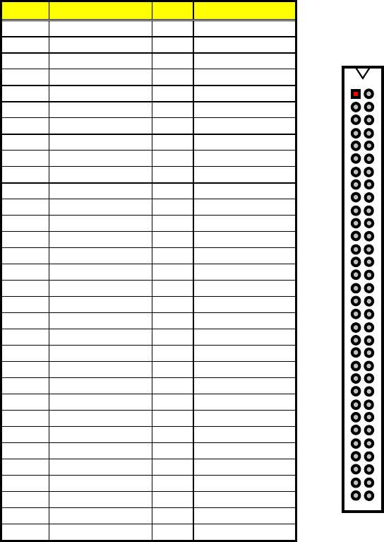
PC1: PC/104 Bus 64-pin Connector
PIN Description PIN Description
1 IOCHECK* 33 GND
2 SD7 34 RESETDRV
3 SD6 35 +5V
4 SD5 36 IRQ9
5 SD4 37 N/C
6 SD3 38 DRQ2
7 SD2 39 -12V
8 SD1 40 OWS
9 SD0 41 +12V
10 IOCHRDY 42 GND
11 AEN 43 SMEMW*
12 SA19 44 SMEMR*
13 SA18 45 IOW*
14 SA17 46 IOR*
15 SA16 47 DACK3*
16 SA15 48 DRQ3
17 SA14 49 DACK1*
18 SA13 50 DRQ1
19 SA12 51 REFRESH*
20 SA11 52 SYSCLK
21 SA10 53 IRQ7
22 SA9 54 IRQ6
23 SA8 55 IRQ5
24 SA7 56 IRQ4
25 SA6 57 IRQ3
26 SA5 58 DACK2*
27 SA4 59 TC
28 SA3 60 BALE
29 SA2 61 +5V
30 SA1 62 OSC
31 SA0 63 GND
32 GND 64 GND
Connector diagram
rotated 90 degrees
clockwise from
original position
133
6432

25
3.26 DiskOnChip Address Setting
The DiskOnChip function allows the system to boot or operate
without a FDD or a HDD. DiskOnChip modules may be formatted as
drive C. With DiskOnChip, user may also execute DOS commands
such as FORMAT, SYS, COPY, XCOPY, DISCOPY, DISKCOMP, etc.
The U31 location onboard the HS-6038 is the DiskOnChip module
socket. If you have another memory device that has a similar memory
capacity with that of the DOC in your system, please set both at
different memory address mapping to avoid mapping area conflicts.
Failing to do so will not make the HS-6038 and the additional memory
device function properly. JP6/JP7 selects the starting memory address
of the DiskOnChip (D.O.C.) to avoid the mapping area with any other
memory devices.
JP6 and JP7: DiskOnChip Address Select
Address JP6 JP7
0C800H~0C9FFH Short 1-2 Short 1-2
0CC00H~0CDFFH Short 1-2 Short 3-4
0D000H~0D1FFH (default) Short 3-4 Short 1-2
0D400H~0D5FFH Short 3-4 Short 3-4
0D800H~0D9FFH Short 5-6 Short 1-2
0DC00H~0DDFFH Short 5-6 Short 3-4
1
4
2
3
1
4
2
3
6
5
JP6 JP7
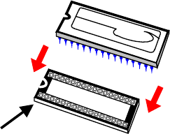
3.26.1 Installing DiskOnChip Modules
When installing a DiskOnChip module onto your board, please take
note of the following:
1. Orient yourself properly with the location of the DiskOnChip
socket. Try to locate the pin 1 location on your socket. Pin
numbers are usually printed on either the component side or the
solder side of your board.
2. Locate the Pin 1 location on your DiskOnChip module. More
often than not, Pin 1 can be found on the lower right corner of
the chip. Please refer to the diagram for the exact location.
3. Once you have figured out where the pin 1 locations are (on
both chip and socket), align the module’s pins on an upright
angle against the socket. Using both thumbs, gently press the
module into the socket until all the pins are secured to their
designations.
26
Pin 1
Location
DiskOnChip
4. The installation is now complete and your module is now ready
for use.
NOTE: If you encounter difficulty installing your DiskOnChip
module,
please consult a qualified technician or engineer to perform the
installation.
3.26.2 Removing DiskOnChip Modules
When removing a DiskOnChip module from its socket, please take
note of the following:
1. Loosen the contact of the module from its socket using a
screwdriver.
2. Insert the screwdriver’s flat head into a gap on either end of the
socket. Do not insert the screwdriver head on either side where
the pins are located. Doing so might damage the pins in the
process.
3. Slowly lift the screwdriver handle upwards. This will disengage
the module from its socket.
NOTE: If you encounter difficulty removing your DiskOnChip
module,
please consult a qualified technician or engineer to remove it for
you.

27
Chapter 4
AMI BIOS Setup
The HS-6038 uses AMI BIOS for the system configuration. The AMI
BIOS setup program is designed to provide the maximum flexibility in
configuring the system by offering various options that could be
selected for end-user requirements. This chapter is written to assist
you in the proper usage of these features.
4.1 Starting Setup
The AMI BIOS is immediately activated when you first power on the
computer. The BIOS reads the system information contained in the
CMOS and begins the process of checking out the system and
configuring it. When it finishes, the BIOS will seek an operating system
on one of the disks and then launch and turn control over to the
operating system.
While the BIOS is in control, the Setup program can be activated in one
of two ways:
1. By pressing <Del> immediately after switching the system on, or
2. By pressing the <Del> key when the following message appears
briefly at the bottom of the screen during the POST (Power On Self
Test).
Press DEL to enter SETUP.
If the message disappears before you respond and you still wish to
enter Setup, restart the system to try again by turning it OFF, then ON
or pressing the "RESET" button on the system case. You may also
restart by simultaneously pressing <Ctrl>, <Alt>, and <Delete> keys. If
you do not press the keys at the correct time and the system does not
boot, an error message will be displayed and you will again be asked
to...
PRESS F1 TO CONTINUE, DEL TO ENTER SETUP

28
4.2 Using Setup
In general, you use the arrow keys to highlight items, press <Enter> to
select, use the <PageUp> and <PageDown> keys to change entries,
press <F1> for help and press <Esc> to quit. The following table
provides more details about how to navigate in the Setup program
using the keyboard.
Up arrow Move to previous item
Down arrow Move to next item
Left arrow Move to the item in the left hand
Right arrow Move to the item in the right hand
Esc key Main Menu -- Quit and not save changes into CMOS
Status Page Setup Menu and Option Page Setup Menu --
Exit current page and return to Main Menu
PgUp key Increase the numeric value or make changes
PgDn key Decrease the numeric value or make changes
+ key Increase the numeric value or make changes
- key Decrease the numeric value or make changes
F1 key General help, only for Status Page Setup Menu and Option
Page Setup Menu
(Shift)F2 key Change color from total 16 colors. F2 to select color
forward, (Shift) F2 to select color backward
F3 key Calendar, only for Status Page Setup Menu
F4 key Reserved
F5 key Restore the previous CMOS value from CMOS, only for
Option Page Setup Menu
F6 key Load the default CMOS value from BIOS default table, only
for Option Page Setup Menu
F7 key Load the default
F8 key Reserved
F9 key Reserved
F10 key Save all the CMOS changes, only for Main Menu
4.2.1 Getting Help
Press F1 to pop up a small help window that describes the appropriate
keys to use and the possible selections for the highlighted item. To exit
the Help Window press <Esc> or the F1 key again.

29
4.3 Main Menu
Once you enter the AMI BIOS CMOS Setup Utility, the Main Menu will
appear on the screen. The Main Menu allows you to select from several
setup functions and two exit choices. Use the arrow keys to select
among the items and press <Enter> to enter the sub-menu.
AMIBIOS HIFLEX SETUP UTILITY – VERSION 1.52
(C)2001 American Megatrends, Inc. All Rights Reserved
HS-6038LV VER:1.1.
Standard CMOS Setup
Advanced CMOS Setup
Advanced Chipset Setup
Power Management Setup
PCI / Plug and Play Setup
Peripheral Setup
Hardware Monitor Setup
Auto-Detect Hard Disks
Change User Password
Change Supervisor Password
Auto Configuration with Optimal Settings
Auto Configuration with Fail Safe Settings
Save Settings and Exit
Exit Without Saving
Standard CMOS setup for changing time, date, hard disk type, etc.
ESC:Exit :Sel F2/F3: Color F10: Save & Exit
NOTE: A brief description of the highlighted choice appears at the bottom
of the screen.

30
4.4 Standard CMOS Setup
The Standard Setup is used for the basic hardware system
configuration. The main function is for Data/Time and Floppy/Hard Disk
Drive settings. Please refer to the following screen for the setup. When
the IDE hard disk drive you are using is larger than 528MB, you must
set the HDD mode to LBA mode. Please use the IDE Setup Utility in
BIOS SETUP to install the HDD correctly.
AMIBIOS SETUP – STANDARD CMOS SETUP
(C)2001 American Megatrends, Inc. All Rights Reserved
Date (mm/dd/yyyy) : Fri Oct 24, 2003 Base Memory :
639 KB
Time (hh/mm/ss) : 19:04:12 Extd Memory :
126 MB
Floppy Drive A: Not Installed
Floppy Drive B: Not Installed
LBA Blk PIO 32Bit
Type Size Cyln Head WPcom Sec Mode Mode Mode Mode
Pri Master : Not Installed
Pri Slave : Not Installed
Sec Master : Not Installed
Sec Slave : Not Installed
Boot Sector Virus Protection : Disabled
Month: Jan - Dec ESC:Exit :Sel
Day: 01 - 30 PgUp/PgDn: Modify
Year: 1980 - 2099 F1:Help F2/F3:Color

31
4.5 Advanced CMOS Setup
This section allows you to configure your system for the basic
operation. You have the opportunity to select the system’s default
speed, boot-up sequence, keyboard operation, shadowing and
security.
AMIBIOS SETUP – STANDARD CMOS SETUP
(C)2001 American Megatrends, Inc. All Rights Reserved
Quick Boot Enabled SAvailable Options:
Pri Master ARMD Emulated as Auto ` Disabled
Pri Slave ARMD Emulated as Auto Enabled
Sec Master ARMD Emulated as Auto
Sec Slave ARMD Emulated as Auto
USB ARMD Emulated as Auto
1st Boot Device Disabled
2nd Boot Device Disabled
3rd Boot Device Disabled
Try Other Boot Devices Yes
Initial Display Mode BIOS
Display Mode at Add-On ROM Init Force BIOS
Floppy Access Control Read-Write
S.M.A.R.T. for Hard Disks Disabled
BootUp Num-Lock On
Floppy Drive Seek Disabled
PS/2 Mouse Support Enabled
Primary Display VGA/EGA
Password Check Setup
Boot To OS/2 No
CPU Serial Number Disabled
L1 Cache Writeback
L2 Cache Writeback
System BIOS Cacheable Disabled
C000,16k Shadow Enabled
C400,16k Shadow Enabled
C800,16k Shadow Enabled
CC00,16k Shadow Disabled
D000,16k Shadow Disabled
D400,16k Shadow Disabled ESC:Exit :Sel
D800,16k Shadow Disabled PgUp/PgDn: Modify
DC00,16k Shadow Disabled TF1:Help F2/F3:Color

32
4.6 Advanced Chipset Setup
This section allows you to configure the system based on the specific
features of the installed chipset. This chipset manages bus speeds and
the access to the system memory resources, such as DRAM and the
external cache. It also coordinates the communications between the
conventional ISA and PCI buses. It must be stated that these items
should never be altered. The default settings have been chosen
because they provide the best operating conditions for your system.
You might consider and make any changes only if you discover that the
data has been lost while using your system.
AMIBIOS SETUP – ADVANCED CHIPSET SETUP
(C)2001 American Megatrends, Inc. All Rights Reserved
CPU Ratio Selection Safe Mode Available Options:
CPU BIST Enable Disabled ` Safe Mode
ICH Delayed Transaction Disabled 5.5x
DMA Collection Buffer Enable Disabled 6.0x
DRAM Page Closing Policy Open 6.5x
Memory Hole Disabled 7.0x
MPS Revision 1.1 7.5x
System memory Frequency 100MHz 8.0x
SDRAM Timing by SPD Disabled 8.5x
DRAM Refresh 15.6us 9.0x
DRAM Cycle time (SCLKs) 7/9 9.5x
CAS# Latency (SCLKs) 3 10.0x
RAS to CAS delay (SCLKs) 3 10.5x
SDRAM RAS# Precharge (SCLKs) 3 11.0x
Internal Graphics Mode Select 1MB 11.5x
Display Cache Window Size 64MB 12.0x
AGP Aperture Window 64MB
Local memory Frequency 100MHz
Initialize Display Cache Memory Enabled
Paging Mode Control Closed
RAS – to CAS Default
CAS Latency Slow
RAS Timing Slow
RAS Precharge Timing Slow
CPU Latency Timer Disabled
USB Function All USB Port ESC:Exit :Sel
USB Device Legacy Support Disabled PgUp/PgDn: Modify
Port 64/60 Emulation Disabled F1:Help F2/F3:Color

33
4.7 Power Management Setup
The Power Management Setup allows user to configure the system for
saving energy in a most effective way while operating in a manner
consistent with his own style of computer use.
AMIBIOS SETUP – POWER MANAGEMENT SETUP
(C)2001 American Megatrends, Inc. All Rights Reserved
ACPI Aware O/S No Available Options:
APIC Interrupt Mode Disabled ` No
Sleep State S1/POS Yes
USB KB/MS Wake Up From S3 Disabled
Power Management/APM Enabled
Suspend Time Out Disabled
Keyboard & PS/2 Mouse Monitor
FDC/LPT/COM Ports Monitor
SB & NSS Audio Ports Ignore
MIDI Ports Ignore
ADLIB Ports Ignore
Primary Master IDE Monitor
Primary Slave IDE Ignore
Secondary Master IDE Monitor
Secondary Slave IDE Ignore
System Thermal Ignore
Power Button Function On/Off
Restore on AC/Power Loss Power On
Wake Up On Ring Disabled
Wake Up On LAN Disabled
Wake Up On PME Disabled
Resume By Alarm Disabled
Alarm Date 15
Alarm Hour 12 ESC:Exit :Sel
Alarm Minute 30 PgUp/PgDn: Modify
Alarm Second 30 F1:Help F2/F3:Color

34
4.8 PCI / Plug and Play Setup
This section describes configuring the PCI bus system. PCI, or
Personal Computer Interconnect, is a system that allows I/O devices to
operate at speeds nearing the speed the CPU itself uses when
communicating with its own special components. This section covers
some very technical items and it is strongly recommended that only
experienced users should make any changes to the default settings.
AMIBIOS SETUP – PCI / PLUG AND PLAY SETUP
(C)2001 American Megatrends, Inc. All Rights Reserved
Plug and Play Aware O/S No Available Options:
Clear NVRAM on Every Boot No ` No
PCT Latency Timer (PCI Clocks) 64 Yes
Primary Graphics Adapter Auto
Allocate IRQ to PCI VGA Yes
PCI IDE BusMaster Disabled
DMA Channel 0 PnP
DMA Channel 1 PnP
DMA Channel 3 PnP
DMA Channel 5 PnP
DMA Channel 6 PnP
DMA Channel 7 PnP
IRQ3 PCI/PnP
IRQ4 PCI/PnP
IRQ5 PCI/PnP
IRQ7 PCI/PnP
IRQ9 PCI/PnP
IRQ10 PCI/PnP
IRQ11 PCI/PnP ESC:Exit
:Sel
IRQ14 PCI/PnP PgUp/PgDn: Modify
IRQ15 PCI/PnP F1:Help F2/F3:Color

35
4.9 Peripheral Setup
The IDE hard drive controllers can support up to two separate hard
drives. These drives have a master/slave relationship that is
determined by the cabling configuration used to attach them to the
controller. Your system supports two IDE controllers--a primary and a
secondary--so you can install up to four separate hard disks.
PIO means Programmed Input/Output. Rather than having the BIOS
issue a series of commands to affect the transfer to or from the disk
drive, PIO allows the BIOS to tell the controller what it wants and then
let the controller and the CPU perform the complete task by them. This
is much simpler and more efficient (also faster).
AMIBIOS SETUP – PERIPHERAL SETUP
(C)2001 American Megatrends, Inc. All Rights Reserved
OnBoard FDC Enabled Available Options:
OnBoard Serial Port A 3F8/COM1 ` Disabled
OnBoard Serial Port B 2F8/COM2 Enabled
Serial Port B Mode Normal
IR Duplex Mode Half Duplex
IR Pin Select IRRX/IRTX
OnBoard Parallel Port 378
Parallel Port Mode Normal
EPP Version N/A
Parallel Port IRQ 7
Parallel Port DMA Channel N/A
Keyboard Power On Function Disabled
Specific Key for Power On N/A
Mouse Power On Function Disabled
On-Chip IDE Both ESC:Exit :Sel
OnBoard Lan Enabled PgUp/PgDn: Modify
F1:Help F2/F3:Color

36
4.10 Hardware Monitor Setup
AMIBIOS SETUP – HARDWARE MONITOR SETUP
(C)2001 American Megatrends, Inc. All Rights Reserved
CPU Temperature Detected by CPU Available Options:
CPU Temperature ` CPU
System Temperature Thermistor
Power Temperature
CPU Fan Speed
Chassis Fan Speed
Power Fan Speed
CPU VID
Vcore
Vtt
Vio
+ 5.000V
+12.000V
-12.000V
- 5.000V ESC:Exit :Sel
Battery PgUp/PgDn: Modify
+5V SB F1:Help F2/F3:Color

37
4.11 Auto-Detect Hard Disks
This option detects the parameters of an IDE hard disk drive, and
automatically enters them into the Standard CMOS Setup screen.
Up to four IDE drives can be detected, with parameters for each
appearing in sequence inside a box. To accept the displayed entries,
press the “Y” key; to skip to the next drive, press the “N” key. If you
accept the values, the parameters will appear listed beside the drive
letter on the screen.
AMIBIOS HIFLEX SETUP UTILITY – VERSION 1.52
(C)2001 American Megatrends, Inc. All Rights Reserved
HS-6038LV VER:1.1.
Standard CMOS Setup
Advanced CMOS Setup
Advanced Chipset Setup
Power Management Setup
PCI / Plug and Play Setup
Peripheral Setup
Hardware Monitor Setup
Auto-Detect Hard Disks
Change User Password
Change Supervisor Password
Auto Configuration with Optimal Settings
Optimal Configuration with Fail Safe Settings
Save Settings and Exit
Exit Without Saving
Standard CMOS setup for changing time, date, hard disk type, etc.
ESC:Exit :Sel F2/F3: Color F10: Save & Exit

38
4.12 Change Supervisor/User Password
AMIBIOS HIFLEX SETUP UTILITY – VERSION 1.52
(C)2001 American Megatrends, Inc. All Rights Reserved
HS-6038LV VER:1.1.
Standard CMOS Setup
Advanced CMOS Setup
Advanced Chipset Setup
Power Management Setup
Enter new supervisor password: _
Change Supervisor Password
Auto Configuration with Optimal Settings
Optimal Configuration with Fail Safe Settings
Save Settings and Exit
Exit Without Saving
Standard CMOS setup for changing time, date, hard disk type, etc.
ESC:Exit :Sel F2/F3: Color F10: Save & Exit
You can set either supervisor or user password, or both of then. The
differences between are:
supervisor password: can enter and change the options of the setup
menus.
user password: just can only enter but do not have the right to change the
options of the setup menus.
When you select this function, the following message will appear at the
center of the screen to assist you in creating a password.
ENTER PASSWORD:
Type the password, up to eight characters in length, and press
<Enter>. The password typed now will clear any previously entered
password from CMOS memory. You will be asked to confirm the
password. Type the password again and press <Enter>. You may
also press <Esc> to abort the selection and not enter a password.
To disable a password, just press <Enter> when you are prompted to
enter the password. A message will confirm the password will be
disabled. Once the password is disabled, the system will boot and you
can enter Setup freely.
PASSWORD DISABLED.

39
When a password has been enabled, you will be prompted to enter it
every time you try to enter Setup. This prevents an unauthorized
person from changing any part of your system configuration.
Additionally, when a password is enabled, you can also require the
BIOS to request a password every time your system is rebooted. This
would prevent unauthorized use of your computer.
You determine when the password is required within the BIOS
Features Setup Menu and its Security option (see Section 3). If the
Security option is set to “System”, the password will be required both at
boot and at entry to Setup. If set to “Setup”, prompting only occurs
when trying to enter Setup.
4.13 Auto Configuration with Optimal
Settings
When you press <Enter> on this item you will get a confirmation dialog
box with a message shown below. This option allows you to
load/restore the BIOS default values permanently stored in the BIOS
ROM. Pressing ‘Y’ loads the BIOS default values for the most stable,
minimal-performance system operations.
AMIBIOS HIFLEX SETUP UTILITY – VERSION 1.52
(C)2001 American Megatrends, Inc. All Rights Reserved
HS-6038LV VER:1.1.
Standard CMOS Setup
Advanced CMOS Setup
Advanced Chipset Setup
Power Management Setup
Load high performance settings (Y/N) ? N
Change Supervisor Password
Auto Configuration with Optimal Settings
Optimal Configuration with Fail Safe Settings
Save Settings and Exit
Exit Without Saving
Standard CMOS setup for changing time, date, hard disk type, etc.
ESC:Exit :Sel F2/F3: Color F10: Save & Exit

40
4.14 Optimal Configuration with Fail
Safe Settings
When you press <Enter> on this item you get a confirmation dialog box
with a message similar to the figure below. This option allows you to
load/restore the default values to your system configuration, optimizing
and enabling all high performance features. Pressing ‘Y’ loads the
default values that are factory settings for optimal performance system
operations.
AMIBIOS HIFLEX SETUP UTILITY – VERSION 1.52
(C)2001 American Megatrends, Inc. All Rights Reserved
HS-6038LV VER:1.1.
Standard CMOS Setup
Advanced CMOS Setup
Advanced Chipset Setup
Power Management Setup
Load failsafe settings (Y/N) ? N
Change Supervisor Password
Auto Configuration with Optimal Settings
Optimal Configuration with Fail Safe Settings
Save Settings and Exit
Exit Without Saving
Standard CMOS setup for changing time, date, hard disk type, etc.
ESC:Exit :Sel F2/F3: Color F10: Save & Exit

41
4.15 Save Settings and Exit
Pressing <Enter> on this item asks for confirmation:
AMIBIOS HIFLEX SETUP UTILITY – VERSION 1.52
(C)2001 American Megatrends, Inc. All Rights Reserved
HS-6038LV VER:1.1.
Standard CMOS Setup
Advanced CMOS Setup
Advanced Chipset Setup
Power Management Setup
Save current settings and exit (Y/N) ? Y
Change Supervisor Password
Auto Configuration with Optimal Settings
Optimal Configuration with Fail Safe Settings
Save Settings and Exit
Exit Without Saving
Standard CMOS setup for changing time, date, hard disk type, etc.
ESC:Exit :Sel F2/F3: Color F10: Save & Exit
Pressing “Y” stores the selections made in the menus in CMOS – a
special section of memory that stays on after you turn your system off.
The next time you boot your computer, the BIOS configures your
system according to the Setup selections stored in CMOS. After saving
the values, the system will restart.

42
4.16 Exit Without Saving
Pressing <Enter> on this item asks for confirmation:
Quit without saving (Y/N)? Y
This allows you to exit Setup without storing and having any change in
CMOS. The previous selections remain in effect. This exits the Setup
utility and restarts your computer.
AMIBIOS HIFLEX SETUP UTILITY – VERSION 1.52
(C)2001 American Megatrends, Inc. All Rights Reserved
HS-6038LV VER:1.1.
Standard CMOS Setup
Advanced CMOS Setup
Advanced Chipset Setup
Power Management Setup
Quit without saving (Y/N) ? N
Change Supervisor Password
Auto Configuration with Optimal Settings
Optimal Configuration with Fail Safe Settings
Save Settings and Exit
Exit Without Saving
Standard CMOS setup for changing time, date, hard disk type, etc.
ESC:Exit :Sel F2/F3: Color F10: Save & Exit
43
Chapter 5
Software Utilities
This chapter contains the detailed information of IDE, VGA, LAN and
Audio driver installation procedures. The utility disk that came with the
delivery package contains an auto-run program that invokes the
installation programs for the IDE, VGA, LAN and Audio drivers. The
following sections describe the installation procedures of each driver
based on Win 95/98, Win 2000 and Win NT operating systems. It is
recommended that you install the drivers matching the sections listed
in this chapter.
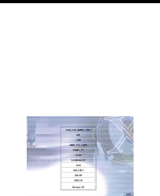
5.1 IDE Driver Installation
5.1.1 Installing Intel 815 Chipset Software
1. Insert Utility CD Disk into your CD ROM drive. The main menu
will pop up as shown below. Select on the IDE button to launch
the installation program.
44
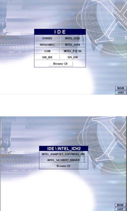
2. Click on the INTEL_ICH2 button to continue.
3. When the IDE \ INTEL_ICH2 box appears on your screen,
click on the INTEL_R&HIPSET_SOFTWARE_INS to install
the IDE plug and play information files into your system.
45
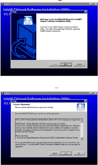
4. Immediately after clicking the IDE butto n in Step 1, the progra m
launches the InstallShield Wizard that will assist you in the
installation process. Click on the Next > button to proceed.
5. The Intel OEM Software License Agreement dialog box then
appears on the screen. Choose Yes to proceed.
46
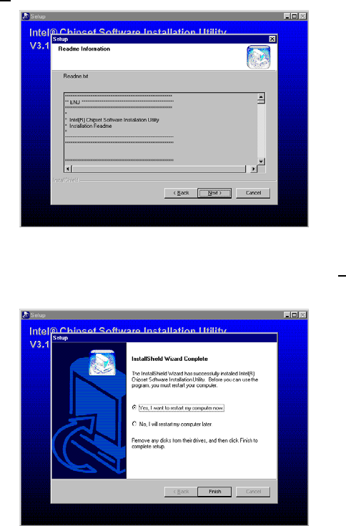
6. When the Readme Information dialog box pops up, just click on
the Next button to proceed.
7. Once the InstallShield Wizard finishes updating your system, it
will prompt you to restart the computer. Tick on the Yes, I want
to restart my computer now followed by a click on the Finish
button to reboot. Only after your computer boots will the new
settings take effect.
47
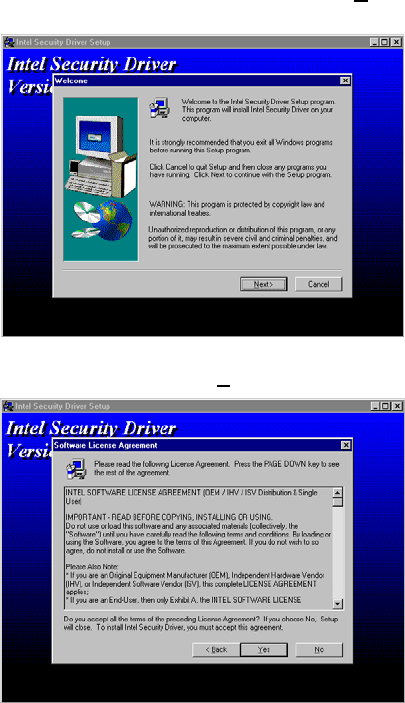
5.1.2 Installing Intel Security Driver
1. Following Steps 1 ~ 3 of the Intel 815 chipset software (from the
preceding section), click on the INTEL_SECURITY_ DRIVER
button. When the dialog box below appears, make sure you close
all other Windows applications then click on the Next > button to
proceed.
2. The Intel OEM Software License Agreement dialog box then
appears on the screen. Choose Yes to proceed.
48
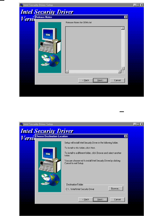
3. When the Release Notes box pops up on the screen, read
through any important information listed before clicking the
Next > button.
4. Setup will then prompt you to specify the path where you would
like the Security driver installed. Select the Next > button after
you have made your path/installation choice.
49
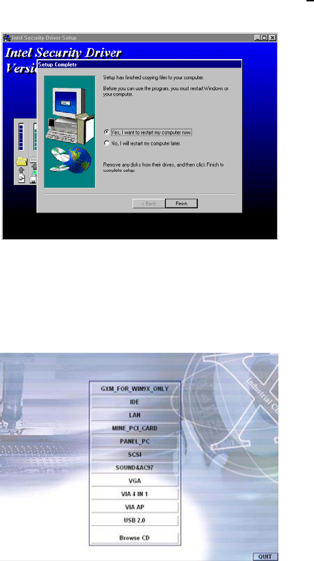
5. Once the setup program finishes copying files into your system, it
will prompt you to restart the computer. Tick on the Yes, I want
to restart my computer now followed by a click on the Finish
button to reboot. Only after your computer boots will the new
settings take effect.
5.2 VGA Driver Installation
5.2.1 Win 95/98
1. After loading the Utility CD-ROM, the program automatically runs
the utility. Press Enter to proceed installing. When the main
utilities window pops up on the screen, select the VGA button.
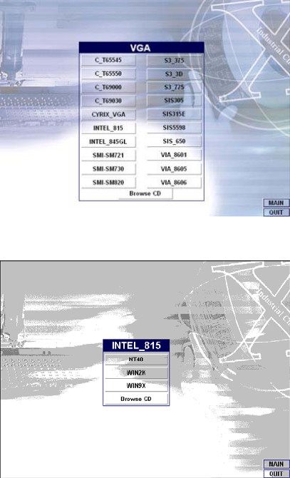
50
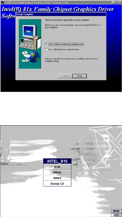
2. When the VGA main utility window is displayed. Select
INTEL_815 to continue.
3. The INTEL_815 window shows up next. Select WIN9X to invoke
the corresponding installation program.
51
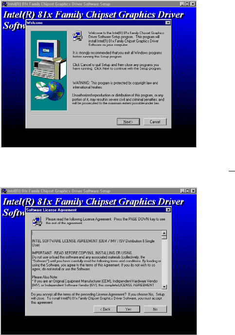
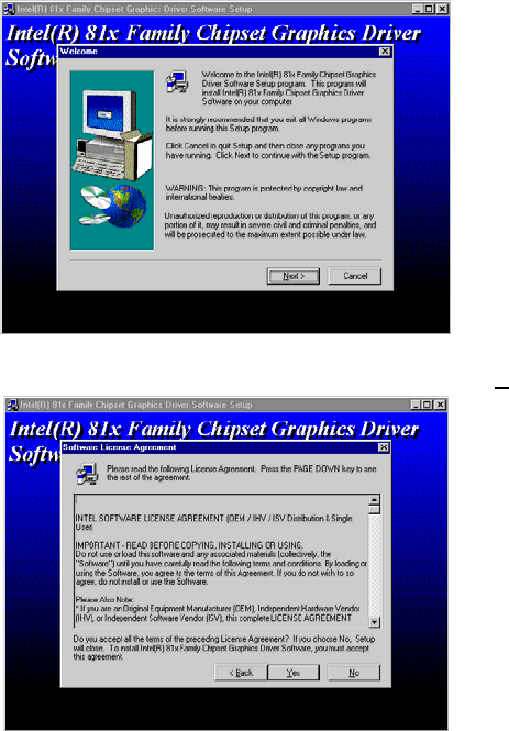
4. The program launches an introduction screen of what graphics
driver it will install. Close all other running Windows applications
then click on the Next > button to proceed.
5. Immediately after clicking on the Next > button, the Intel OEM
Software License Agreement pops up on the screen. Choose Yes
to proceed.
52
6. The VGA driver utility program starts copying files needed by
your Win98 to invoke the VGA capabilities. Once finishes, the
system will prompt you to restart your computer. Tick on the
Yes, I want to restart my computer now followed by a click
on the Finish button to complete the installation.
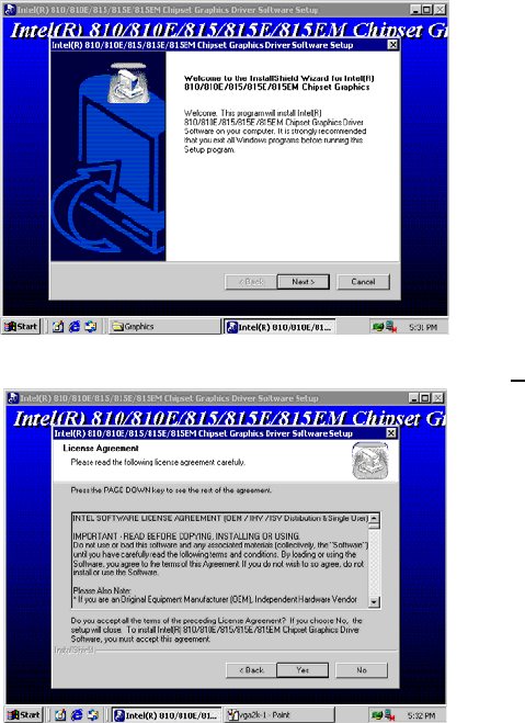
5.2.2 Win 2000
1. Follow steps 1 and 2 from the Win9x installation procedure.
When the INTEL_815 window shows up, select WIN2K to invoke
the installation program to your Win 2000 OS.
53
2. The program launches the InstallShield Wizard for Intel
810/810E/815/815E/815EM chipset graphics. Close all other
running Windows applications then click on the Next > button.
3. Immediately after clicking the Next > button, the Intel OEM
Software License Agreement pops up on the screen. Choose Yes.
4. Once the utility program finishes copying and installing all the
necessary files into your system, it will prompt you to restart
your computer. Tick on the Yes, I want to restart my
computer now followed by a click on the Finish button to
complete the installation.
54
5.2.3 Win NT4.0
1. Follow steps 1 and 2 from the Win9x installation procedure.
When the INTEL_815 window shows up, select NT40 to invoke
the installation program to your Win 2000 OS.
2. The program launches an introduction screen of the graphics it
will install. Close all other running Windows applications and then
click on the Next > button to proceed.
3. Immediately after clicking on the Next > button, the Intel OEM
Software License Agreement pops on the screen. Choose Yes.
4. Once the utility program finishes copying and installing all the
necessary files into your system, it will prompt you to restart
your computer. Tick on the Yes, I want to restart my
computer now followed by a click on the Finish button to
complete the installation.
55
5.3 LAN Driver Installation
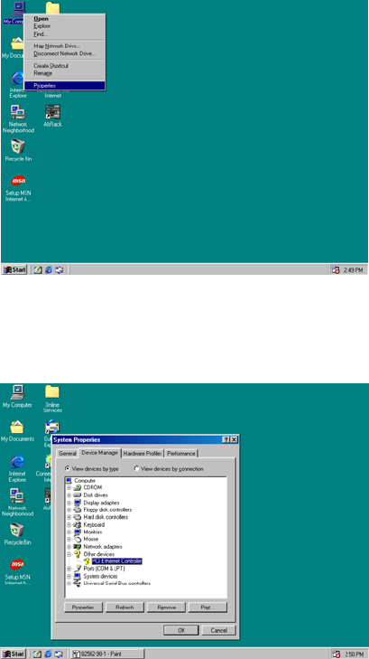
5.3.1 Win 95/98
1. Right click on My Computer icon then scroll to the Properties
item from the pop-up menu.
2. Select Device Manager from the top menu bar. A list of all
devices installed appears, scroll down to the Other devices and
then select on PCI Ethernet Controller. Select the Properties
button to access the details of this unknown device. Refer to the
following screen shot for a clearer explanation of this step.
56
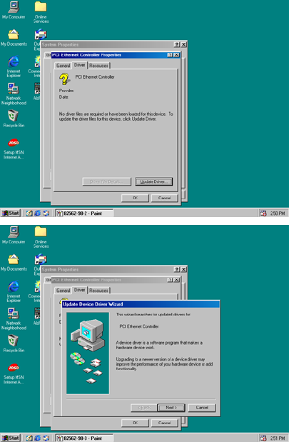
3. Once the PCI Ethernet Controller Properties screen pops up
on the screen, click on the Update Driver … button to launch
the Update Device Driver Wizard screen.
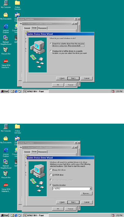
4. The succeeding screen then lets you choose whether to search for
a better driver for the LAN or display the available list of drivers.
Select Search for a better driver than the one your device
is using now followed by a click on the Next > button.
57
5. The wizard program will then require you to specify the location
of the driver file. Tick on the Specify a location: and type or
select the path where the driver files exist (c:\i82562). Click on
the Next > button to proceed.
58
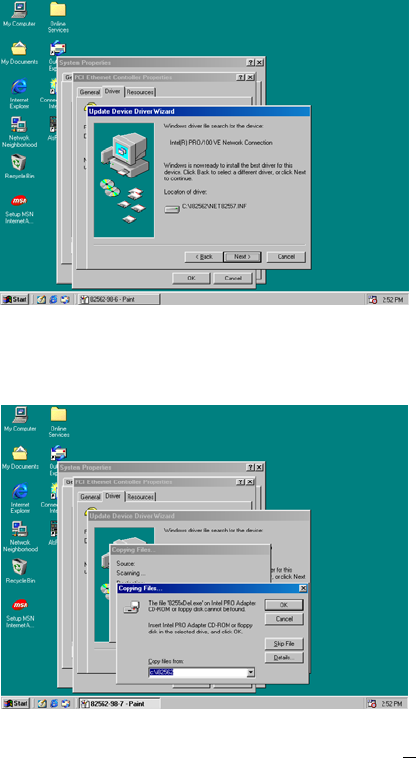
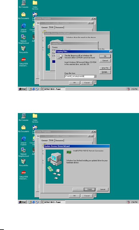
6. The program now starts copying the file(s) needed by your
Win98. When t he program fails to se ek fo r 8255xD el. exe fil e from
your specified location, it will prompt you to specify the path
where the Intel Pro Adapter exists.
7. With the Utility CD Disk on your CD drive, key in
d:\win98_se\setup\win98 on the blank space below Copy files
from: then press the OK button.
59
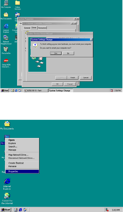
8. When the program finishes updating and copying files for the
Intel Pro/100VE Network Connection, click on the Finish button
to proceed.
9. For the new hardware settings to take effect and to complete the
installation process, you must restart your computer when the
System Settings Change window below pops up. Click on the
Yes button to complete the installation.
60
5.3.2 Win 2000
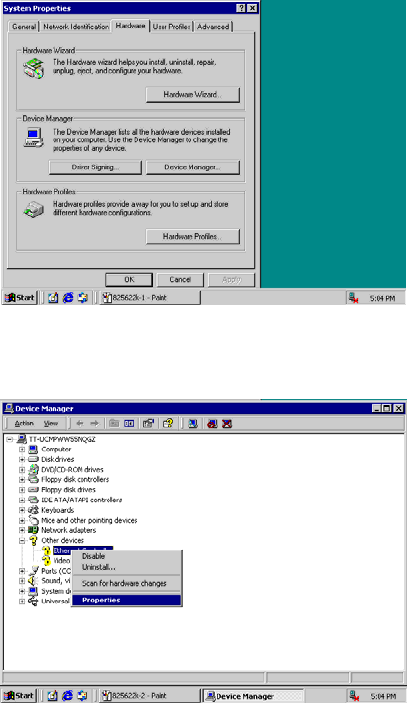
1. Right click on My Computer icon and then scroll to the
Properties item from the pop-up menu.
61
2. When the System Properties window pops up on the screen, click
on the Device Manager button.
3. A list of all devices installed appears, scroll down to the Other
devices and then right click on Ethernet Controller to select
the Properties button. Refer to the following screen shot for a
clearer explanation of this step.
62
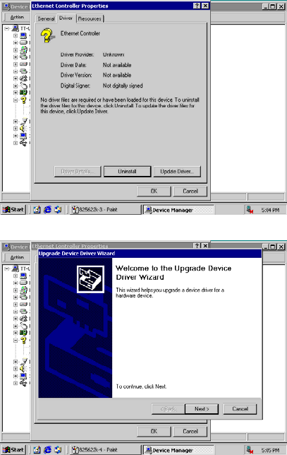
4. Once the Ethernet Controller Properties screen pops on the
screen, click on the Update Driver … button to launch up the
Update Device Driver Wizard screen. Once the Upgrade
Device Driver Wizard screen pops up on the screen, click
Update Driver … to launch the Win 2000 driver installation
program.
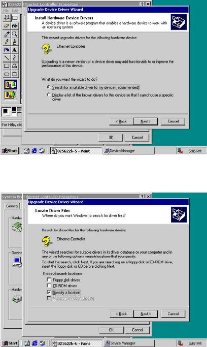
5. Click on Next > button to proceed with the installation.
63
6. The wizard will then inform you the unknown device it detected
from the system. Since the Win2000 driver list does not include
Intel chip driver onboard HS-6038, tick Search for a better
driver than the one your device is using now followed by a
click on the Next > button to continue.
7. The wizard program will then prompt you to specify the location
where it will start searching for the driver. Tick on the Specify a
location: and then click on the Next > button to proceed.
64
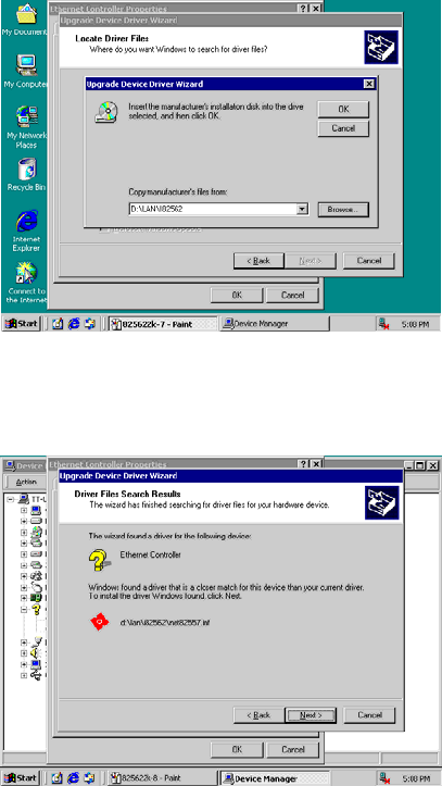
8. The wizard program will then require you to insert the
manufacturer disk at your specified location (entered at the Copy
manufacturer’s files from: space) of the driver file. With your
Utility CD disk inserted in the drive, type d:lan\i82562 then click
on the OK button to proceed.
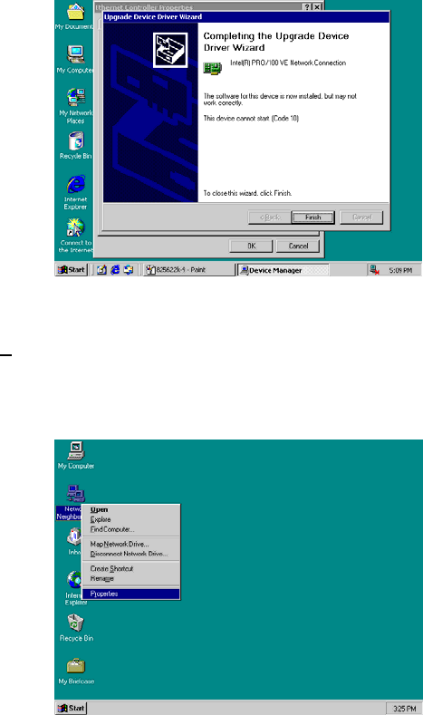
9. The wizard program will start to scan and search for the driver(s)
located at your specified location; after which, the wizard
program will show the result of its search. When it finds a more
suitable driver fitting your device, it will list the driver name and
path. Just click on the Next > button to continue installing.
65
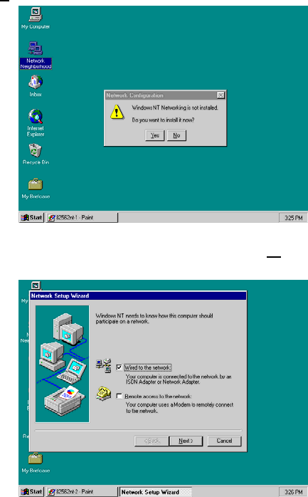
10. When the program finishes updating and copying files for the
Intel Pro/100VE Network Connection, click Finish to proceed.
11. For the new hardware settings to take effect and to complete the
installation process, you must restart your computer when the
System Settings Change window below pops up. Click on the
Yes button to complete the installation.
5.3.3 Win NT
1. Right click on Network Neighborhood icon and then scroll to
the Properties item from the pop-up menu.
66
2. The Network Configuration dialog box then appears, notifying the
user that there is no Windows NT Networking available. Click on
the Yes button to start the installation process.
3. The Network Setup Wizard will then ask you to identify the
network connection of your computer. Select Wired to the
network and click on the Next > to continue.
67
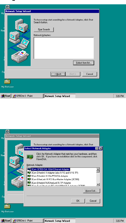
4. The succeeding screen then indicated that the wizard will initially
search for Network Adapter from the available list of drivers.
Select on Start Search.
5. When it is done searching for available network drivers, the
wizard will show a list and allow you to locate and choose the
appropriate Network Adapter. Since the LAN device driver is in
the Utility CD Disk, select on Have Disk … to proceed.
68
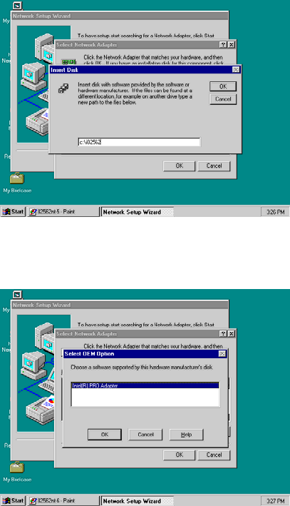
6. The wizard program will then require you to insert the
manufacturer disk and specify the location of the driver file (i.e.,
c:\i82562). Click on the OK button to proceed.
7. The Select OEM Option then appears, prompting you to select the
software supported by the network hardware device you will
install. Select Intel(R) PRO Adapter and click on the OK button to
continue installing.
69
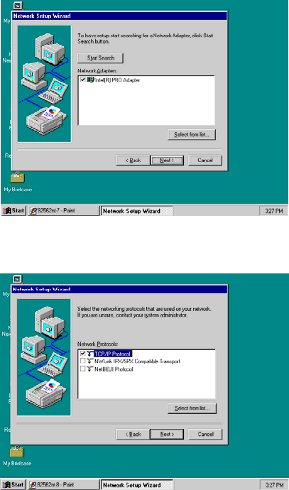
8. The wizard program now displays on the screen that it has
detected the Intel() PRO Adapter. Click on the Next > button to
continue installing.
9. The wizard program now prompts you to specify the networking
protocols used on your network structure. Tick on the TCP/IP
Protocol and click on the Next > button to proceed.
70
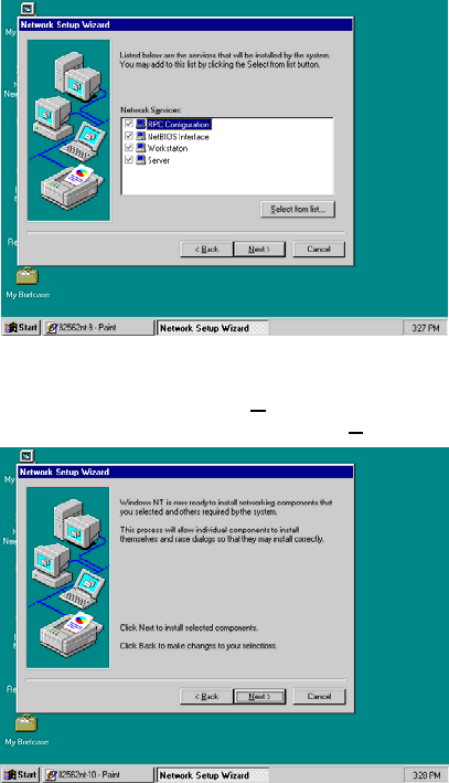
10. The next screen will allow you to customize the Network Services
the wizard program intends to install. Tick services as needed
and then click on the Next > button to continue.
11. The Network Setup Wizard then prompts you that it is ready to
install the network components based on your selection. You may
start installing by clicking on he Next > button or make
modifications on your choices using the < Back button.
71
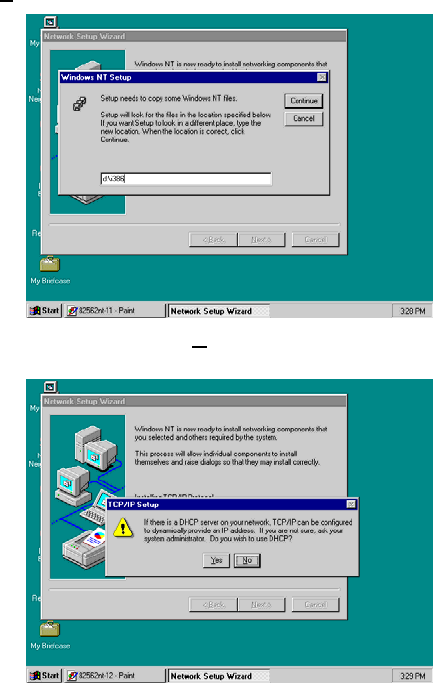
12. The Network Setup Wizard will then need to copy the drive file(s).
Specify the path of your device driver(s) (i.e., d:\i386) and click
the Continue button.
13. Choose the default entry, No, when the following screen pops up
on the screen.
72
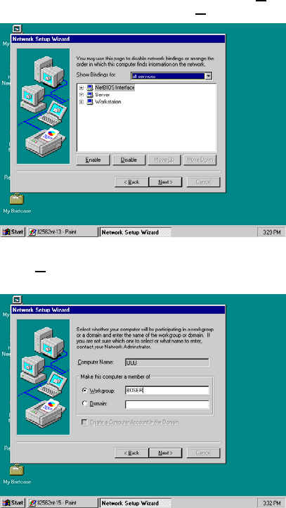
14. If you need to disable network bindings on the network services
installed, select the service and then click on the Disable button.
Otherwise, proceed by clicking on the Next > button.
15. Select which member (Workgroup or Domain) you belong to.
Click on the Next > button after identifying the network group
installed on your computer.
73
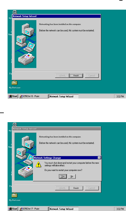
16. The wizard program then informs you that Networking is now
installed on your system. You must restart your computer to
make the setting changes take effect. Click on the Finish button
to close the wizard program.
17. When the following dialog box pops up on your screen, click on
the Yes button to restart your computer and make the setting
changes take effect.
74
5.4 Audio Driver Installation
5.4.1 Win 95/98
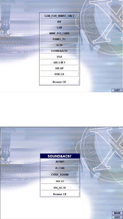
1. After loading the Utility CD-ROM, the program automatically runs
the utility. Press Enter to proceed installing. When the main
utilities window pops up on the screen, select SOUND&AC7.
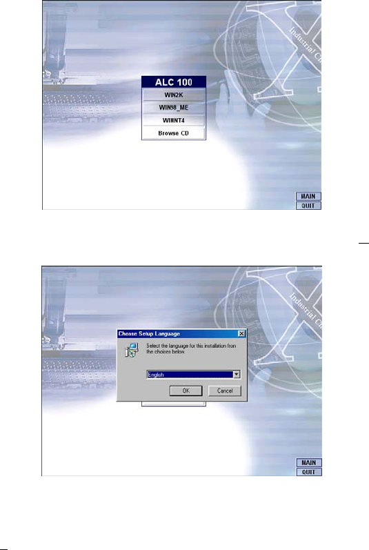
2. The succeeding screen will then show you the SOUND&AC97
main menu. Select on ALC 100 to continue installation. When
the ALC100 dialog box appears, pick on WIN98_ME and it will
take you to the ALC 100 menu. Refer to the following screen
shots for a graphical description of this step.
75
3. Select the language you intend to use for the installation. The
default is English. After making your choice, press on the OK
button to proceed.
4. Once the InstallShield Wizard completes the operation and
update of your AC’97 driver, it will ask you to remove disks from
their drives, and prompt you to restart your system. Tick on the
Yes, I want to restart my computer now. Afterwards, click on the
Finish button to complete the installation process. The system
changes you made will take effect after the system restarts.
76
5.4.2 Win 2000
1. Following steps 1 and 2 of the Win95/98 AC97 installation, select
WIN2K button when the ALC100 dialog box appears on the
screen.
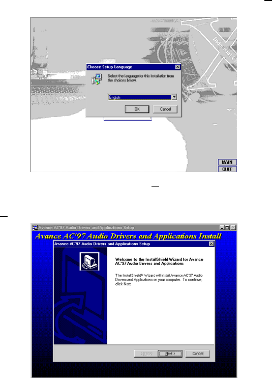
2. Select the language you intend to use for the installation. The
default is English. After making your choice, press on the OK
button to proceed.
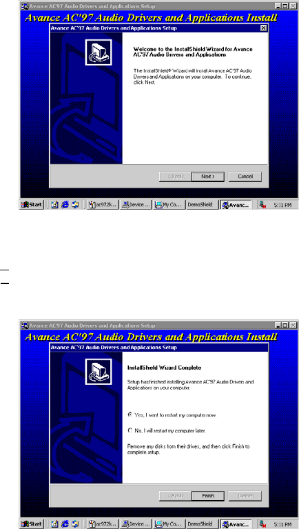
3. Immediately after clicking on the OK button from the preceding
step, the Advance AC’97 Audio Drivers and Applications
Setup dialog box will appear on the screen. Just click on the
Next > button to continue.
77
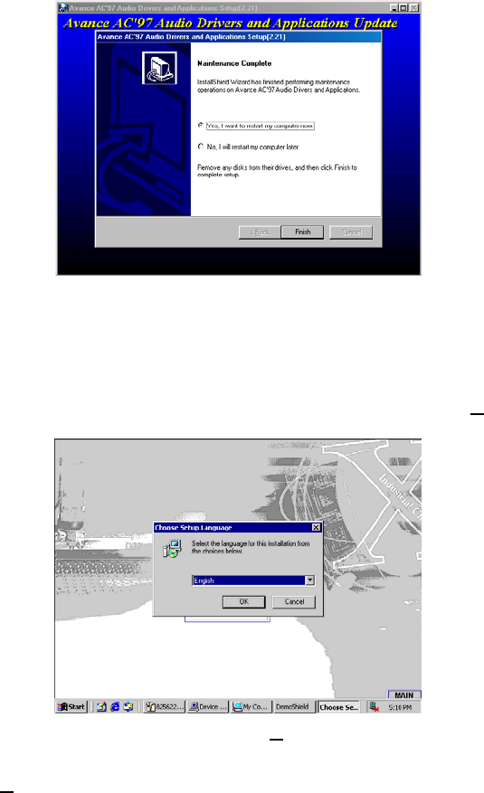
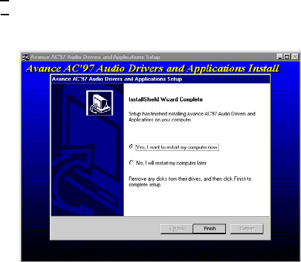
4. Once the InstallShield Wizard completes the operation and
update of your AC’97 driver, it will ask you to remove any disks
from their drives, and prompt you to restart your system. Tick on
the Yes, I want to restart my computer now. Afterwards, click on
the Finish button to complete the installation process. The
system changes you made will take effect after the system
restarts.
78
5.4.3 Win NT
1. Following steps 1 and 2 of the Win95/98 OR step 1 of Win 2000
AC97 installation, select WINNT button when the ALC100 dialog
box appears on the screen.
2. Select the language you intend to use for the installation. The
default is English. After making your choice, press on the OK
button to proceed.
3. Immediately after clicking on the OK button from the preceding
step, the Advance AC’97 Audio Drivers and Applications
Setup dialog box will appear on the screen. Just click on the
Next > button to continue.
79
4. Once the InstallShield Wizard completes the operation and
update of your AC’97 driver, it will ask you to remove any disks
from their drives, and prompt you to restart your system. Tick on
the Yes, I want to restart my computer now. Afterwards, click on
the Finish button to complete the installation process. The
system changes you made will take effect after the system
restarts.
80
This page intentionally left blank.
