TriGem Computer ALL-IN-ONE-SER PC equipped with certified 802.11abg module User Manual Averatec F1 User s Guide US PD
TriGem Computer, Inc PC equipped with certified 802.11abg module Averatec F1 User s Guide US PD
User manual

TM
All-In-One PC User’s Guide

i
Regulations Information
FCC-B Radio Frequency Interference Statement
This equipment has been tested and found to comply with the limits for a Class B digital device,
pursuant to part 15 of the FCC rules. These limits are designed to provide reasonable protection
against harmful interference in a residential installation. This equipment generates, uses and can
radiate radio frequency energy and, if not installed and used in accordance with the instructions,
may cause harmful interference to radio communications. However, there is no guarantee that
interference will not occur in a particular installation. If this equipment does cause harmful
interference to radio or television reception, which can be determined by turning the equipment
off and on, the user is encouraged to try to correct the interference by one or more of the
following measures :
✓Reorient or relocate the receiving antenna.
✓Increase the separation between the equipment and receiver.
✓Connect the equipment into an outlet on a circuit different from that to which the receiver is
connected.
✓Consult the dealer or an experienced radio TV technician for help.
Note
✓The changes or modifications not expressly approved by the party responsible for compliance could
void the user’s authority to operate the equipment.
✓Shield interface cables and AC power cord, if any must be used in order to comply with the emission
limits.

ii
FCC RF Radiation Exposure Statement
This equipment complies with FCC RF radiation exposure limits set forth for an uncontrolled
environment. This equipment should be installed and operated with a minimum distance of 20
centimeters between the radiator and your body. This transmitter must not be co-located or
operated in conjunction with any other antenna or transmitter.
FCC Conditions
This device complies with part 15 of the FCC Rules. Operation is subject to the following two
conditions :
1. This device may not cause harmful interference.
2. This device must accept any interference received, including interference that may cause
undesired operation.

iii
Optical Device Drive Notice
CAUTION
✓This appliance contains a laser system and is classified as a “CLASS 1 LASER PRODUCT.” To use this
model properly, read the instruction manual carefully and keep this manual for your future reference.
In case of any trouble with this model, please contact your nearest “AUTHORIZED service station.” To
prevent direct exposure to the laser beam, do not try to open the enclosure.

iv
Macrovision Notice
This product incorporates copyright protection technology that is protected by U.S. patents and
other intellectual property rights. Use of this copyright protection technology must be
authorized by Macrovision, and is intended for home and other limited viewing uses only unless
otherwise authorized by Macrovision. Reverse engineering or disassembly is prohibited.
Safety Instructions
1. Read the safety instructions carefully and thoroughly.
2. Save this User Guide for possible use later.
3. Keep this equipment away from humidity and high temperature.
4. Lay this equipment on a stable surface before setting it up.
5. The openings on the enclosure are used for air convection and to prevent the equipment from
overheating. Do not cover the openings.
6. Make sure that the power voltage is within its safety range and has been adjusted properly to
the value of 100~240V before connecting the equipment to the power inlet.
7. Place the power cord in a way that people are unlikely to step on it. Do not place anything on
the power cord.
8. Always unplug the power cord before inserting any add-on card or module.
9. All cautions and warnings on the equipment should be noted.
10. If any of the following situations arises, get the equipment checked by a service personnel:
✓The power cord or plug is damaged.
✓Liquid has penetrated into the equipment.
✓The equipment has been exposed to moisture.
✓The equipment has not worked well or you can not get it work according to Users Manual.
✓The equipment was dropped and damaged.
✓The equipment has obvious signs of breakage.
11. Never pour any liquid into the opening that could damage the equipment or cause an
electrical shock.
v
WEEE Statement
12. Do not leave the equipment in an unconditioned environment with a storage temperature of
60°C (140°F) or above, which may damage the equipment.
13. To prevent explosion caused by improper battery replacement, use the same or equivalent
type of battery recommended by the manufacturer only.
vi
vii

viii
Table of Content
What is the Averatec All-In-One PC? 1
Turning On and Shutting Off 2
Using the Wireless Keyboard, Mouse and Remote Control 4
Adjusting the Brightness of the Monitor 8
Adjusting the Speaker Volume 9
Connecting Your Multi-Channel Speakers 10
Using the Optical Drive 12
Connect to the Internet 15
Using Your Webcam 16
Using the Wireless LAN 18
Using the Multi-Card Reader 20
Watching TV 21
System SETUP 25
Expanding the Main Memory 32

1
What is the Averatec All-In-One PC?
The Averatec All-In-One PC is an all inclusive desktop PC that is designed for quick installation
and easy use without taking up much desk space.
Features
Integrated PC and LCD Monitor
The Averatec All-In-One PC is equipped with a 22" LCD monitor and fully functional PC. Nothing
else is needed. The All-In-One PC is designed to be a complete plug-and-play system.
Less Cabling and More Portability
The Averatec All-In-One PC eliminates all those messy cables, enhances system portability and
results in less clutter.
Everything’s Included!
The Averatec All-In-One PC includes everything necessary to be immediately productive. An
industry-leading 22" widescreen LCD monitor coupled with an advanced Intel® Pentium®
processor to handle all your entertainment and productivity applications. Additionally, the
Averatec All-In-One PC comes with the following features:
• A huge, super-fast hard drive for all your storage requirements.
• A convenient slot-loading Dual Layer DVD burner, making access a breeze.
• A web cam for video chatting, recording and picture taking.
• A wireless full-size keyboard and mouse for ultimate comfort.
• A wireless remote to drive your Microsoft® Media Center experience.
2
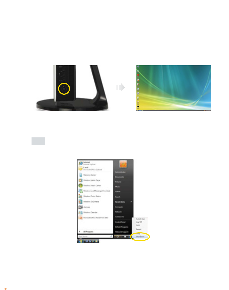
Turning On and Shutting Off
Turning off
Turning on
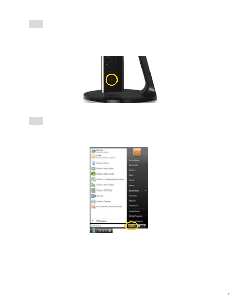
Press the power button on the right side of the PC.
Case 1
Click <Start> to turn off computer.
Click start and select <Shut Down>. Turn off computer screen displays.
3
Case 2
Press the power button on the right side of the PC.
After closing all programs,the PC will be turned off. If the system is operating
abnormally, you can reboot the PC by holding down the Power button until the PC
turns off. Then press the Power button again to boot back up.
Case 3
Power saving mode.
Saves your session and puts the computer in a lower-power state so that you can
quickly resume working.
4
Using the Wireless Keyboard, Mouse and
Remote Control
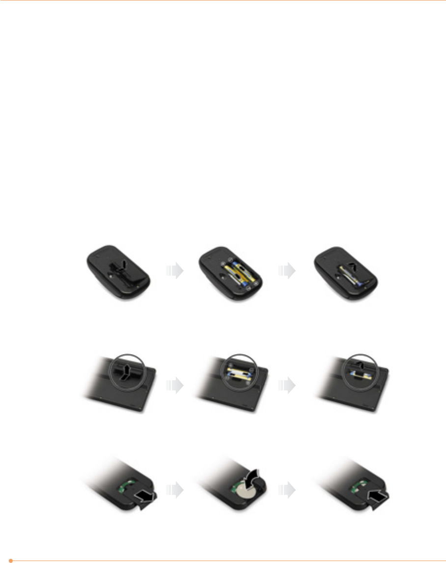
Inserting the batteries
To use the wireless keyboard, mouse and remote control, you will need to install the batteries.
1. Place the wireless keyboard, mouse and remote control upside down and remove the battery
covers from them.
2. Insert the batteries into the wireless devices. Be sure to install the battery with the correct
polarity.
3. Replace the cover of the wireless devices.
Wireless keyboard
Wireless mouse
Remote control
5
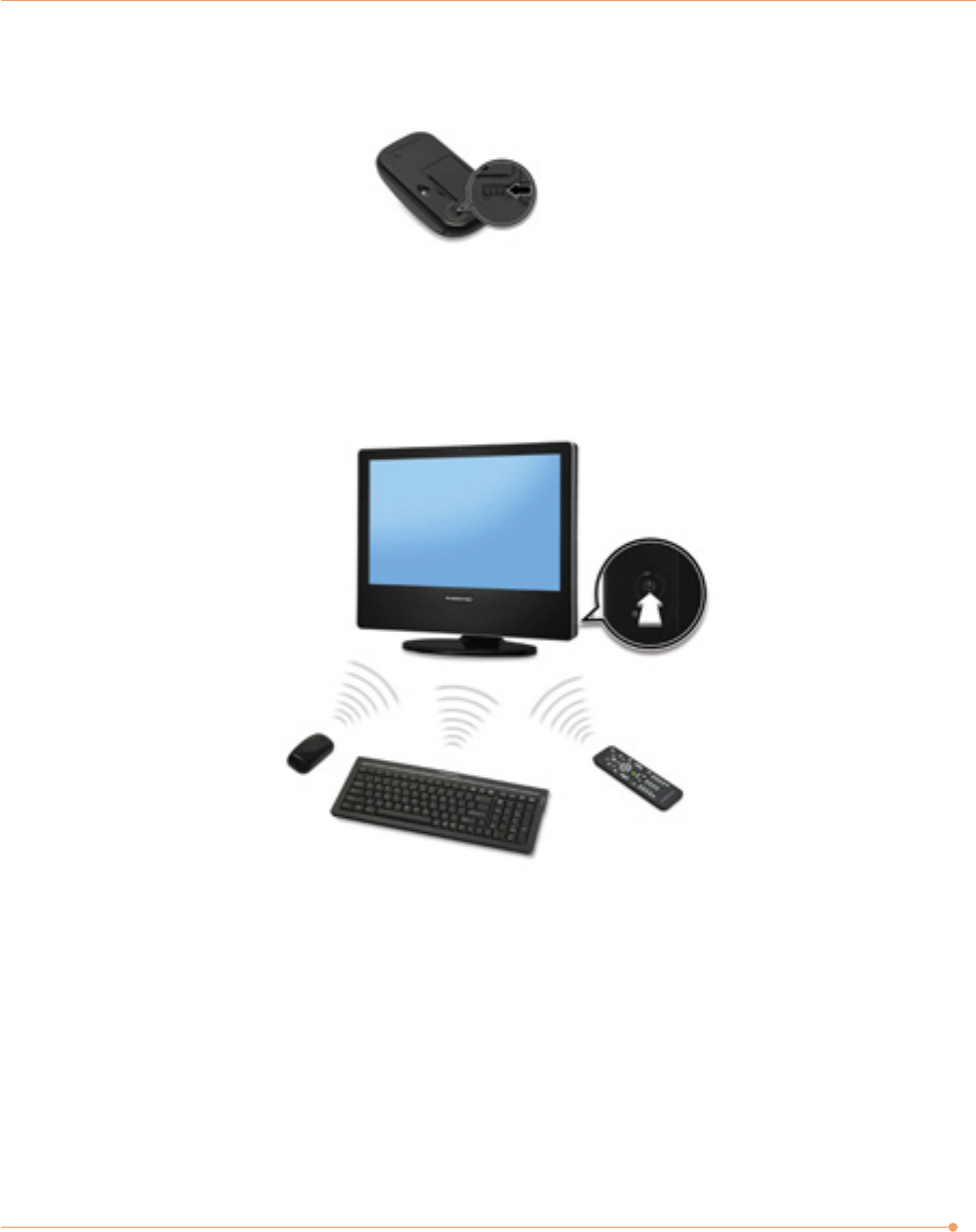
Turning on the computer
Turn on the computer by pressing the power button on the right side, then check each wireless
device works properly with your computer.
4. Set the ON/OFF switch to the ON position on the bottom side of the mouse.
6
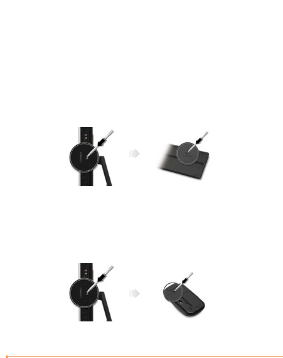
Re-setting the ID Channel with Your Wireless Devices
Your wireless devices were connected and sync’d to the computer at the factory setting, so you
can use them with your computer without any additional sync’ing.
If you need to re-set the ID channel of your system and wireless devices for any reason, follow
these instructions:
1. Press the connect button on the right side of the computer with a tip of a pencil or paperclip
for 1 to 2 seconds.
2. Press the connect button on the bottom of the wireless keyboard for 2 to 5 seconds.
Wireless keyboard
1. Turn on the wireless mouse.
2. Press the connect button on the right side of the computer with a tip of a pencil or paperclip
for 1 to 2 seconds.
3. Press the connect button on the bottom of the wireless mouse for 2 to 5 seconds
Wireless mouse
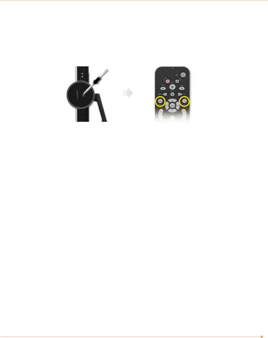
7
1. Press the connect button on the right side of the computer with a tip of a pencil or paperclip
for 1 to 2 seconds.
2. Press the <Back> and <More> buttons simultaneously for 3 to 5 seconds on the remote control.
Remote control
8
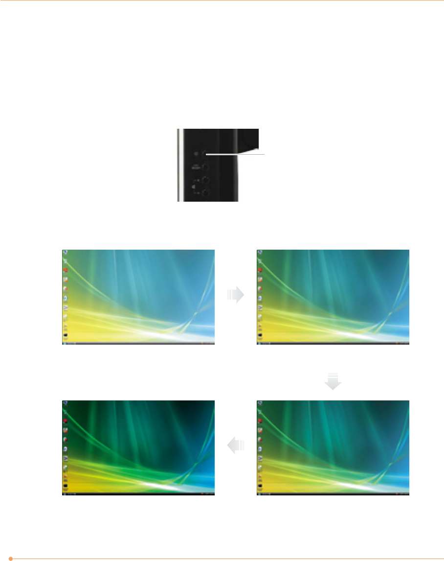
Brightness Control button
100% (For brighter display) 90%
Using the brightness control button
50%(For darker display) 75%
Adjusting the Brightness of the Monitor
You can adjust the brightness by clicking the brightness control button on the right side of
the LCD panel. There are 4 levels of LCD brightness adjustment available. Each press of the
brightness control button will cycle through each level.
9
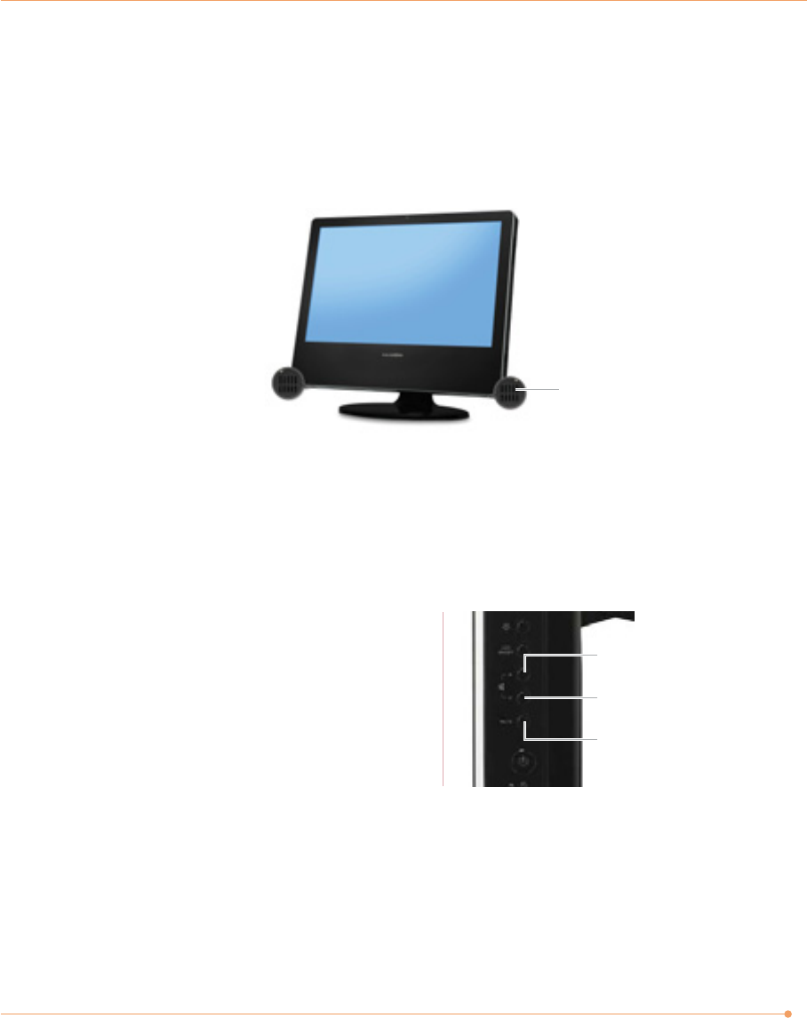
Adjusting the Speaker Volume
Volume button (Up/Down)
To adjust the volume level, press the top volume button to increase the volume level and the
bottom volume button to decrease the volume level.
Mute button
To mute the speaker sound, press it
once to enable mute and press it again
to disable mute.
Volume button(Up)
Volume button(Down)
Speaker
Mute button
The Speaker volume level can be adjusted easily with the button located on the bottom side of
the LCD panel.
10
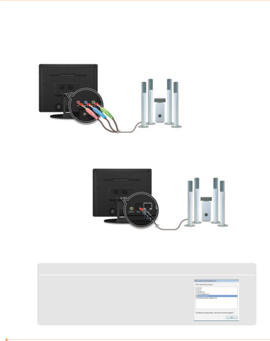
Connecting Your Multi-Channel Speakers
Connect the speakers to microphone, line-in and line-out jacks
Connect the speakers to SPDIF jack
Multi-channel speakers
(optional)
Multi-channel speakers
(optional)
or
Note
✓Connecting the speakers will cause a window to appear confirming
detection of the device.
✓When configured for 5.1 audio speaker setup, the MICROPHONE,
LINE-IN and LINE-OUT all function as INPUT JACKS).
AV Receiver
(optional)
11
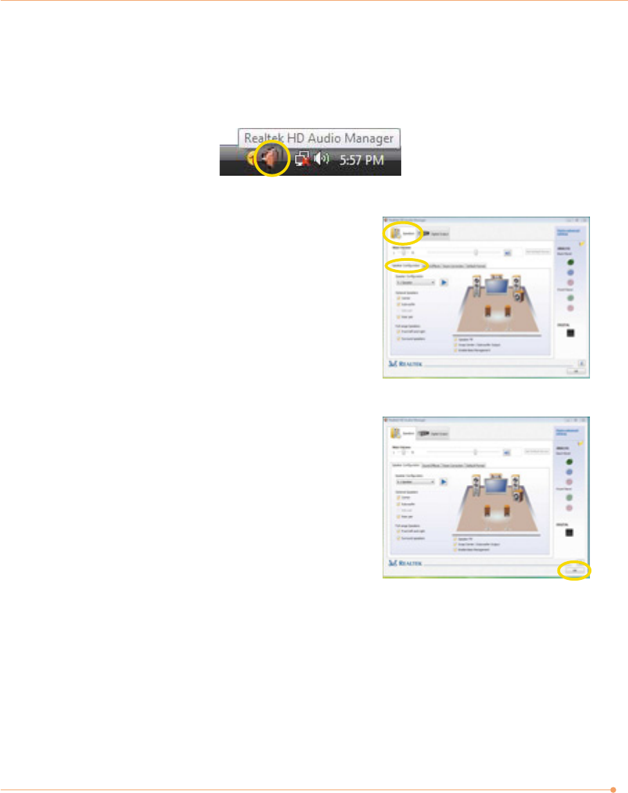
To use multi-channel speakers you should verify that the sound setting is adjusted correctly. To
set the multi-channel speakers, follow these steps.
1. Double click Realtek HD Audio Manager icon.
Adjusting volume
The Averatec All-In-One PC has built-in speakers on the front and back of the system.You can
adjust the volume by clicking the volume adjustment buttons located on the right side of the
LCD panel and / or by using the volume control feature in Windows Vista.
2. Click Speaker Configuration tab and click
5.1 speaker.
3. Click OK button.
Using the Optical Drive
The Averatec All-in-One PC is fitted with a slot-type or slim-type optical drive (COMBO or DVD
Recorder).
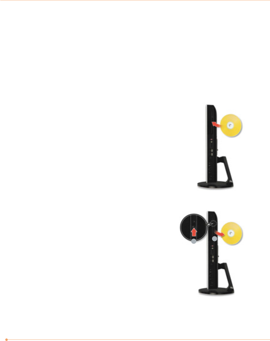
Slot-loading CD drive
1. Insert CD/DVD
With the system powered on, insert a CD/DVD into the
CD/DVD drive.(Slide the CD/DVD into the system with the disc
label facing up. If the label side is facing down, the CD will be
ejected automatically after two minutes.)
2. Eject CD/DVD
Press the <Eject CD/DVD> button to eject the CD.
12
12
13
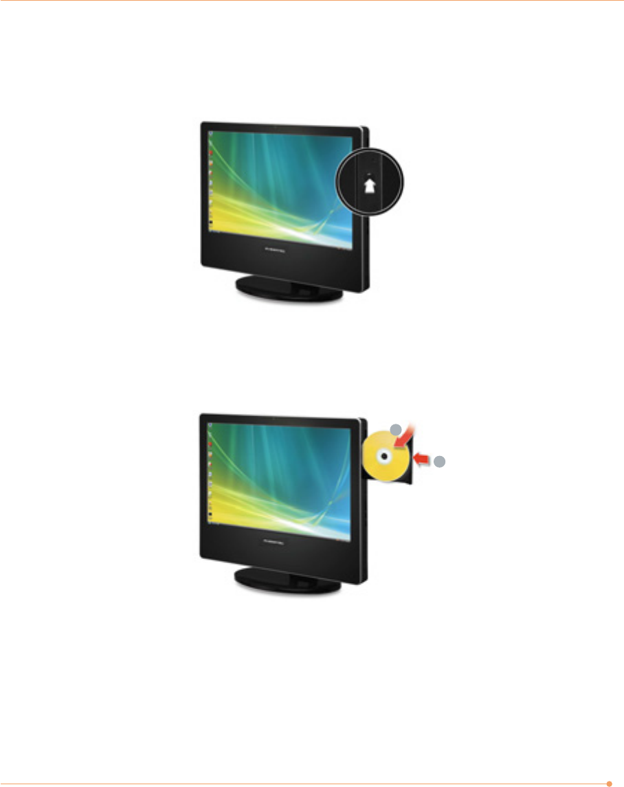
Tray-loading CD drive
1. Press the Eject button of the CD/DVD drive.
2. Insert CD/DVD
Insert CD/DVD in the CD/DVD drive and place CD/DVD label side front.Press the CD/DVD
Drive.
3. Eject CD/DVD
Press the Eject button of the CD/DVD drive on the right side of the Averatec All-In-One PC.
You can then remove the CD/DVD.
1
2
14
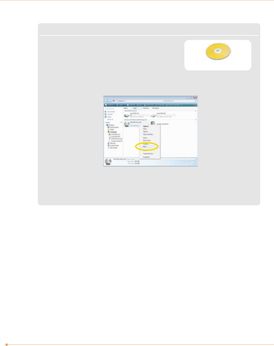
Note
✓This system is fitted with a slot-loading or tray-loading optical
drive. CDs that are not of the standard size cannot be used in
this product.
✓If you can not eject a CD/DVD from the drive, click Start, choose Computer, right-click on the
CD/DVD drive that the CD/DVD is in and choose Eject in the popup menu.
✓Make sure CD/DVD is not inserted upside down.(CD label side facing toward front of PC).
✓Labels on CD/DVD may cause noise when CD/DVD drive is working. Remove labels on CD/DVD for
safe use.
CD 120mm
15
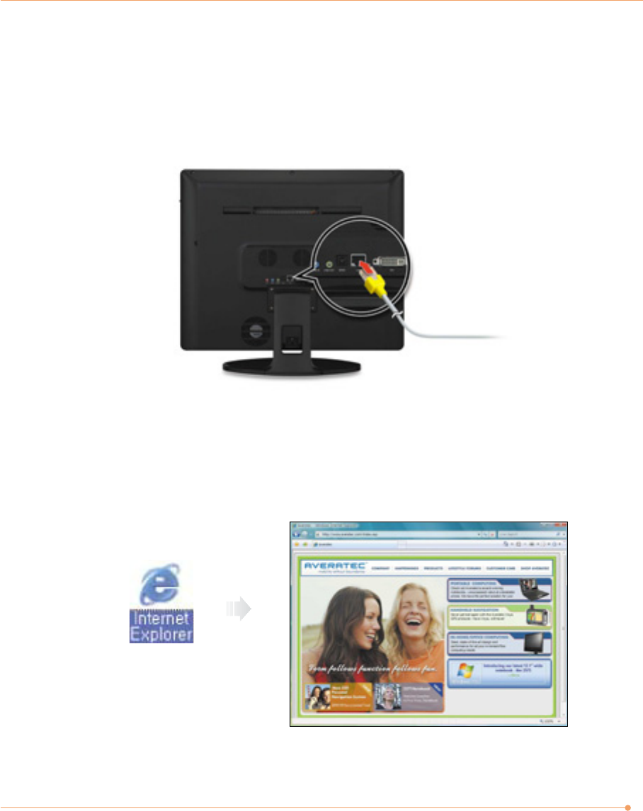
1. Press the power button and the Windows Vista start screen will appear. Connect a LAN cable
to the LAN connector as shown in the figure below.
2. Configure the communication settings for the system based on your communication
environment. When connecting to the Internet via an internet service provider, contact the
service provider for more information on required communication settings.
3. Launch Internet Explorer or other communication software.
Connect to the Internet
16
You can take photos and chat with your friends.
Take photos
Double click the Webcam program. An amber light on the webcam LED indicates your PC is
ready to take photos.
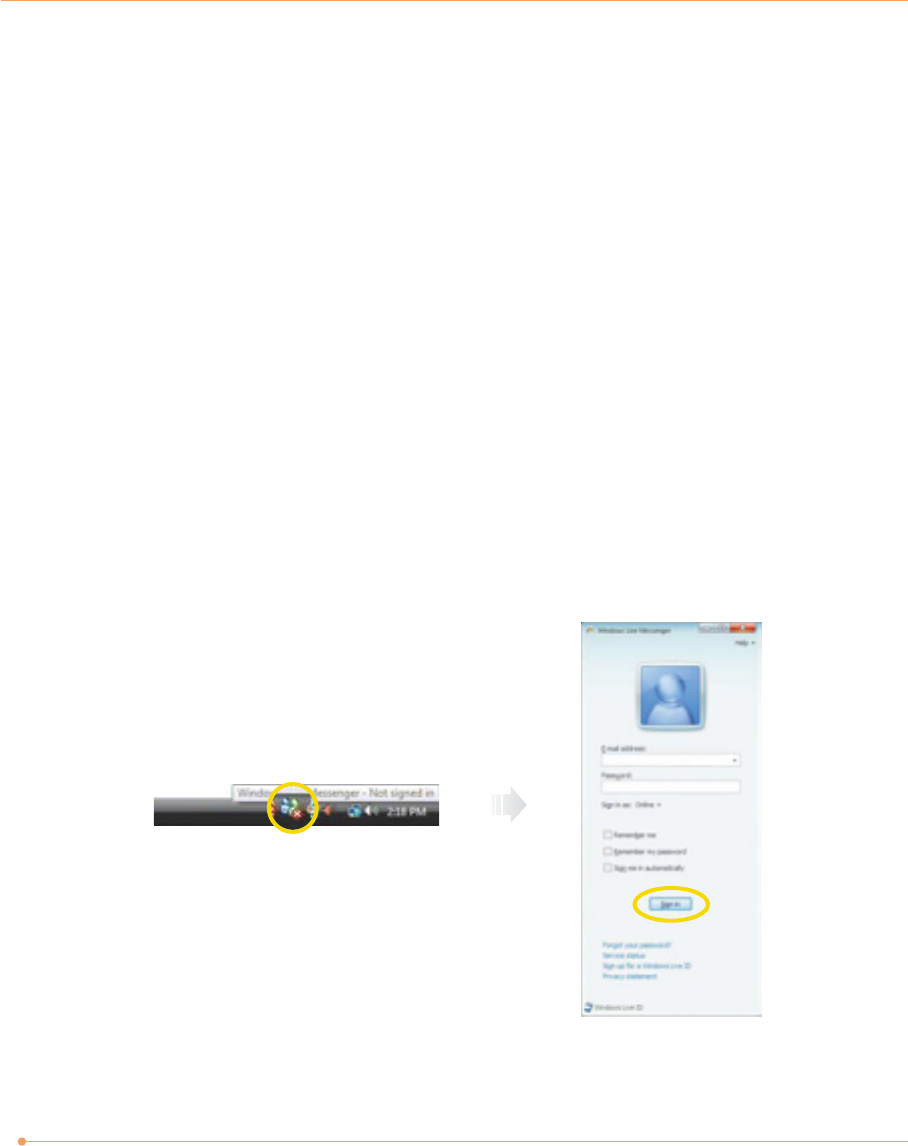
Video chatting
To chat with video, both your system and the system of the person you want to chat with must
have a web camera or a CCD camera installed. You also need to download and install a
messenger program. The screen that you will see varies depending on the type of the
messenger program you’re using.
1. Run the messenger program to register your user email address. When the messenger is
ready. double-click on the Windows Messenger icon. Select Sign in.
Using Your Webcam
17
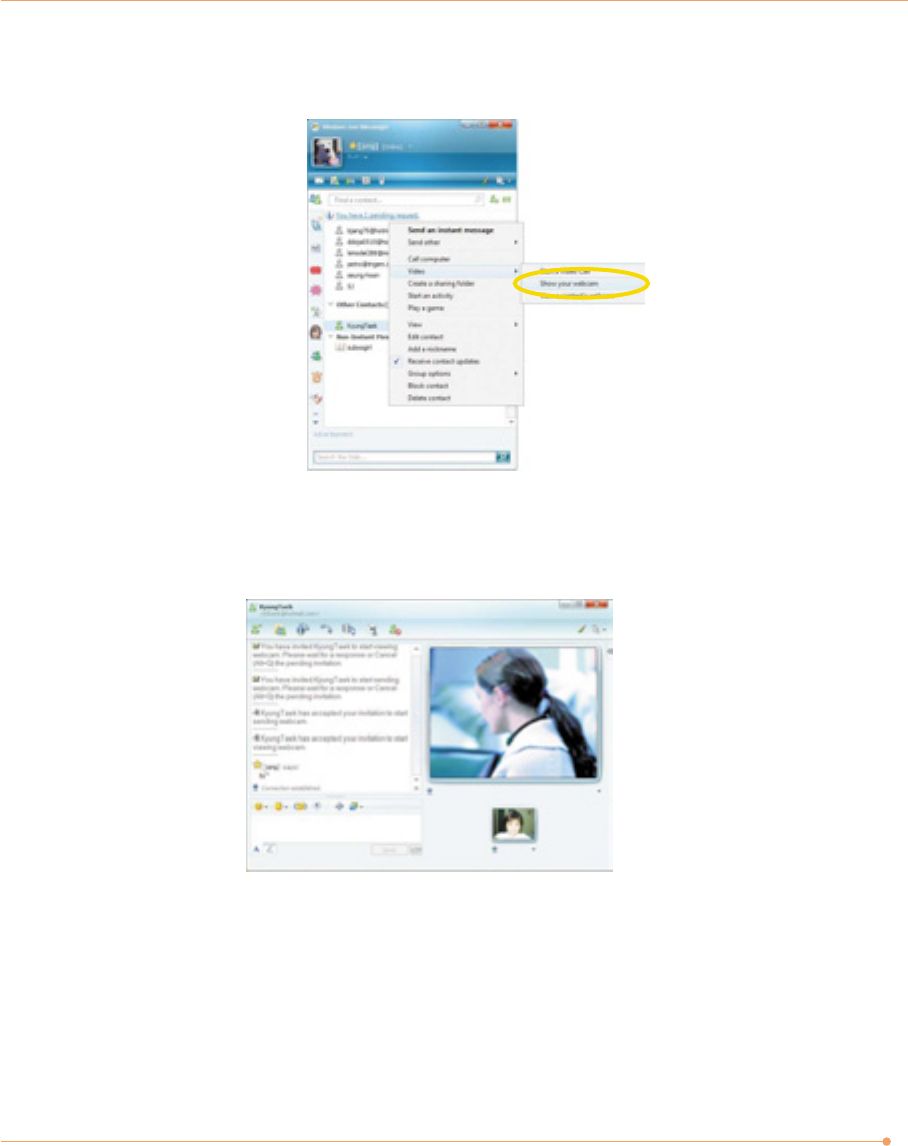
2. Right-click on your chat partner and then select Show your webcam, as illustrated below.
3. Now you’re ready to start chatting!

18
To use a wireless network in an office environment where APs (Access Points) are installed, see
the following instructions. (The example used here explains how to use the basic Windows
configuration features to configure the system. You can also use the program that comes with
the wireless LAN card to configure the network.)
1. Right-click on the Wireless Network icon
on the status bar, and then select Connect
to a network.
2. If there is an AP-enabled environment, a list of available APs will appear. Click the item you
want to connect to, and click Connect.
Using the Wireless LAN
19
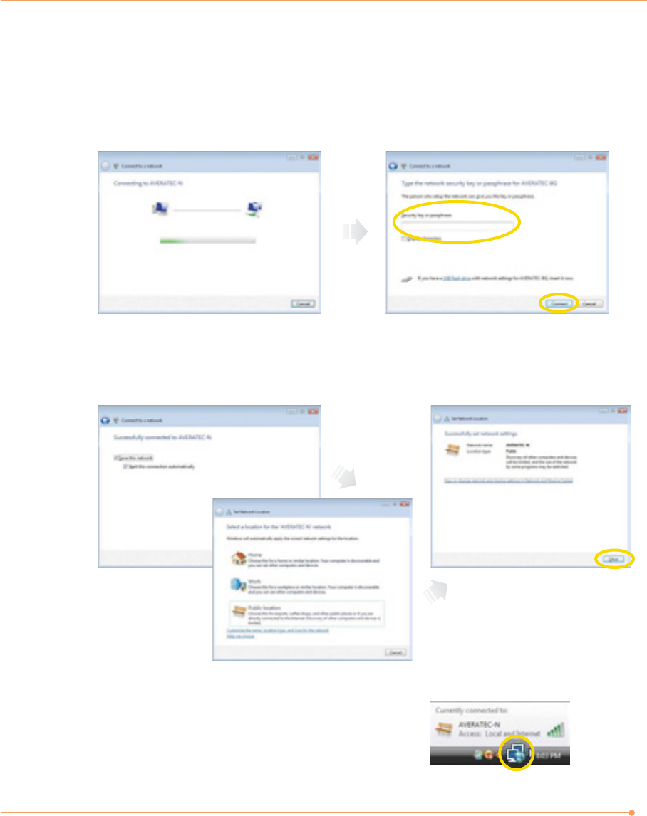
4. When the Successfully connected to xxxxx window appears, confirm the settings and then
click Close.
5. Once connection is successfully established, the
network icon on the status bar will change its
shape.
Select the right items for your
environment, and click Close.
3. A window will appear displaying Connecting to xxxxx (Where XXXXX is the name of your
router/AP). If a Security key or password is set up, a window will appear where you can
enter the security key or password. Enter the security key or password, and click Connect.
(The window will not appear if no security key or password is set up.)
20
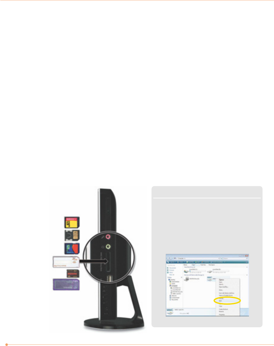
Insert cards with label
side facing toward the
back of the PC.
MS
MS-PRO
MS-PRO Duo
SD
MMC
RS-MMC
Averatec's All-In-One PC accepts 4 types of multi-media cards into the multi-card reader slot on
the right side of the PC.
Multi-Media card
SD (Secure Digital™), MS-PRO™, MS-PRO™ Duo, MS(Memory Stick™), MMC(MultiMediaCard™),
RS-MMC
Inserting the multi-media card
To insert correctly, refer to the pictures. The cards are not inserted completely, the tip of the
cards will remain out of the slot. (Insert cards with label side facing toward the back of the
PC.)
Removing multi-media card
Grip the tip of the card and take it out from the slot.
(Do not remove the card while you are using it, as you could corrupt the contents.)
Using the Multi-Card Reader
Note
✓Click the <Start> menu and select Computer.
On the Computer screen, right-click on the
Combo Socket icon and select Eject.
✓ This does not physically eject the media card.
However, it does ensure all data is written to
the media card prior to the physical removal
of the card
21
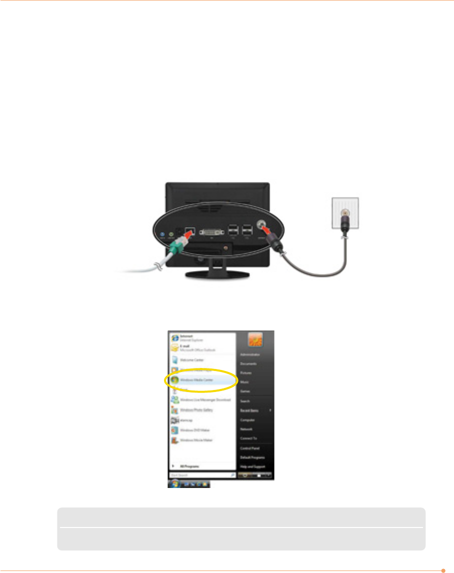
You can connect a TV Antenna to the PC.
Connecting an external antenna cable directly to the
system to watch TV
1. Connect Antenna cable to TV tuner.
2. Click Start, and the select Windows Media Center.
Watching TV
Note
✓ When the Start screen appears, on your first use, select Quick Installation and then click <OK>.
22
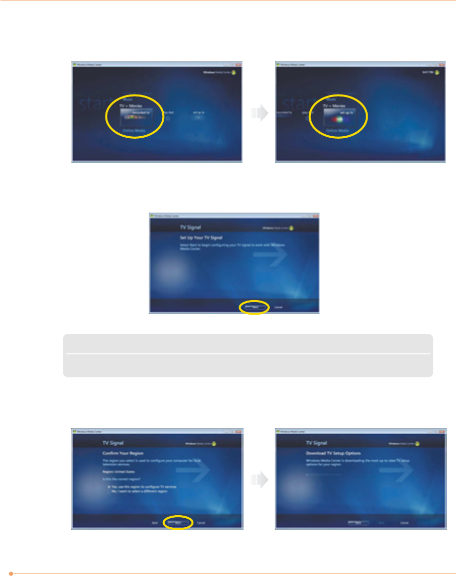
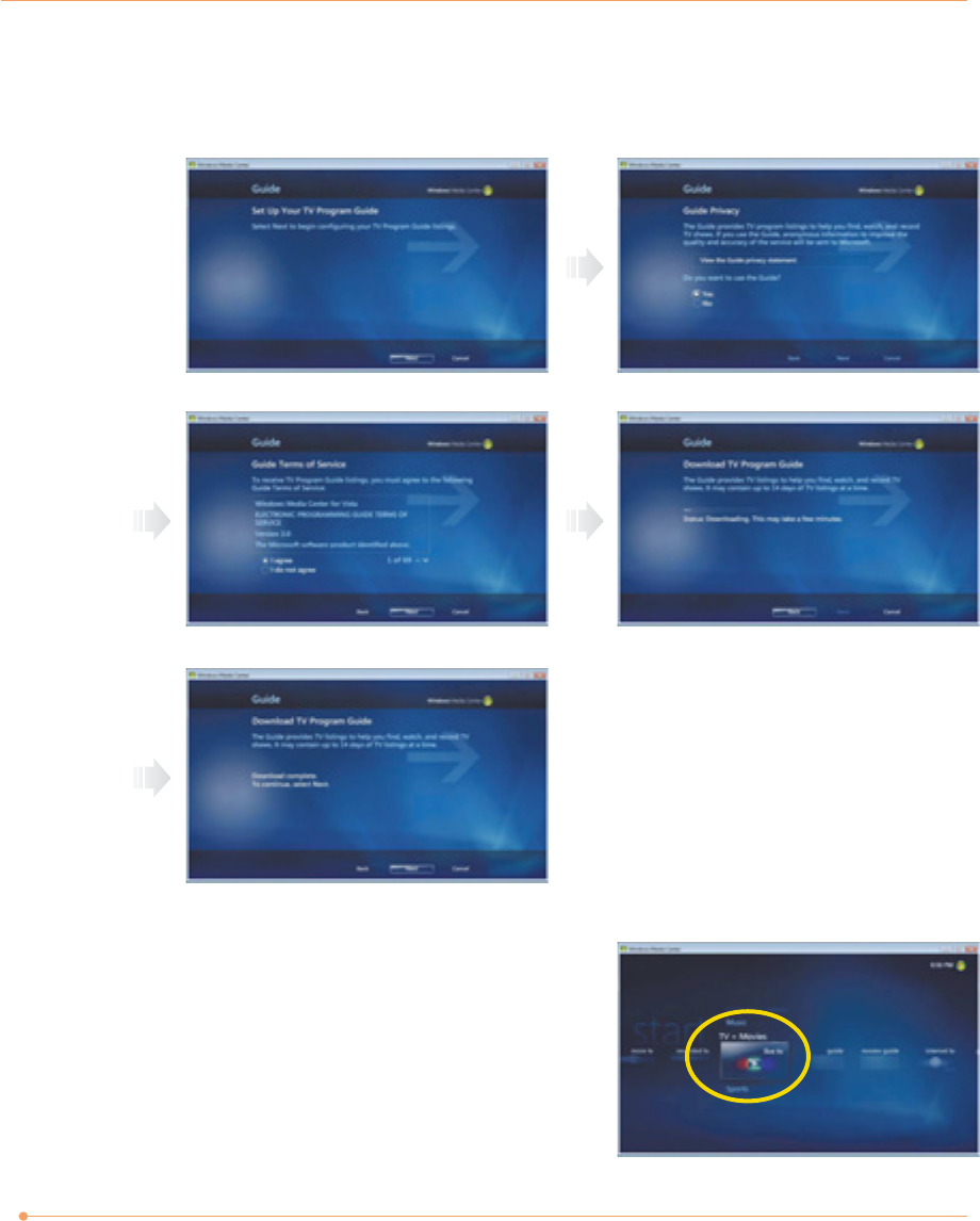
3. Click TV + Movies. To set up the TV , follow the instructions on the screens.
4. When the TV Signal screen appears, click Next.
Note
✓ If you haven’t already done so, connect to the Internet.
5. When the Confirm Your Region screen appears, choose your region and then click Next.
23
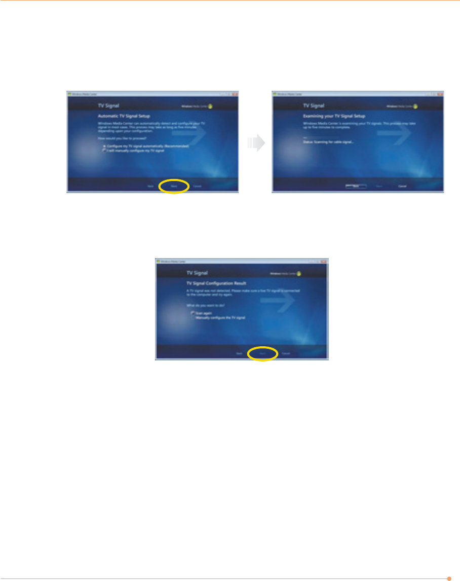
6. When the Automatic TV Signal Setup screen appears, select how you would like to proceed
and then click Next. (Choosing Configure my TV signal automatically is recommended
here.)
7. If TV signals are configured normally, select Yes and then click Next. (If necessary, you can
manually configure TV signals.)
24
8. When the Guide screen appears, follow the online instructions to install the program. (The
installation method varies depending on the user environment.)
9. In the TV+Movies menu, move to live TV
and click on it. Now you are set to watch TV.

25
System SETUP
For System Setup, setup only the items that you need. Note that incorrect settings of Setup
items could result in system malfunction.
Start System Setup
After powering on the system, press <Del> to enter the System Setup screen.
BIOS Action Keys
Leaves a sub-menu to return to the previous menu
OR exits the BIOS setup while saving changes.
Shows the Sub Menu
ESC Exit
Enter Select
Function Key Command Description
Shows the Help ScreenF1 General Help
Saves changes and reboots the computer.F10 Save and Exit
Selects the next field.<Tab> Select a field
Selects the next item.Select an item
-, + value Selects the next value within a field.
26
BIOS Setup Menu
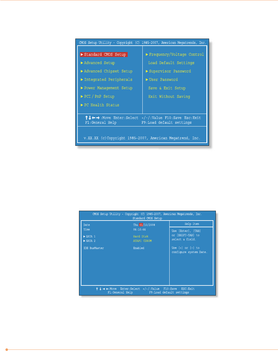
Standard CMOS Setup Menu
Sets most standard specifications for the system, such as the time, date, HDD settings, and FDD
size and capacity.
27
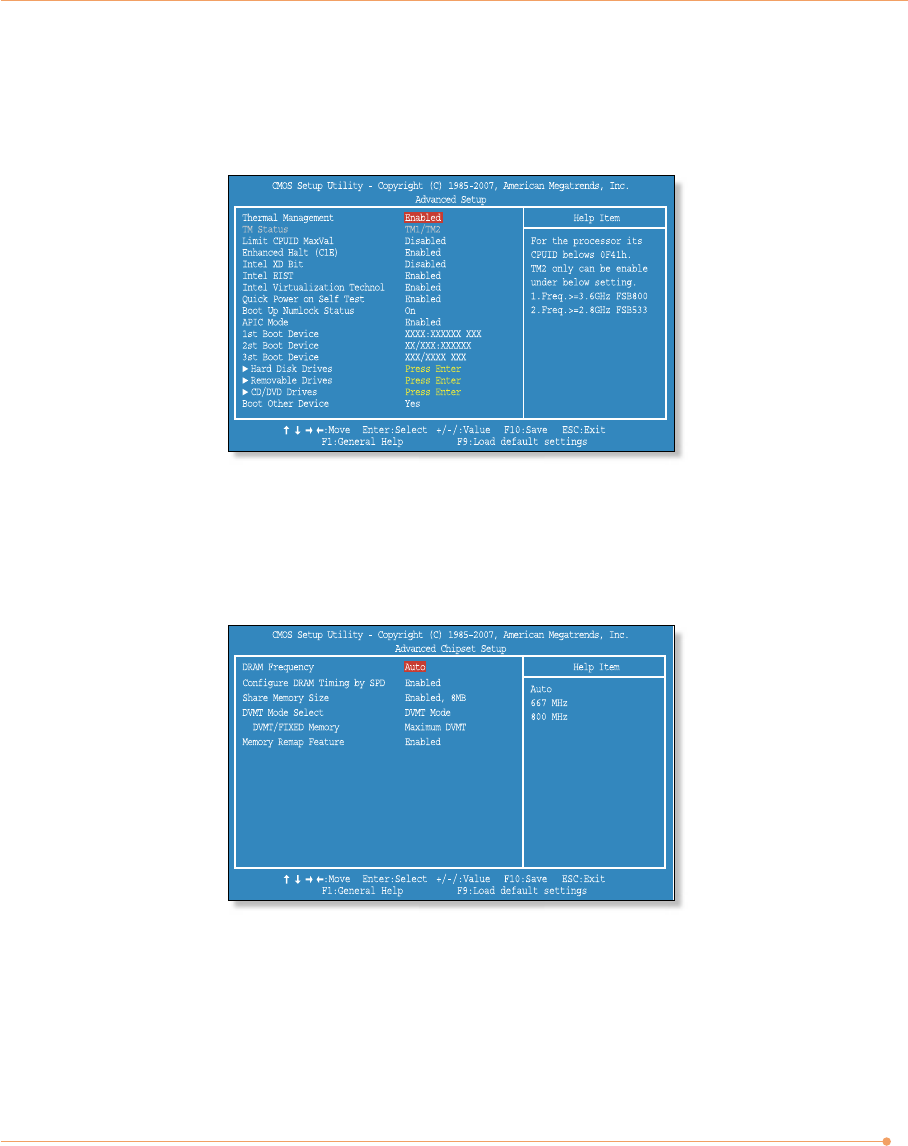
Advanced Setup Menu
Sets up key items related to the system’s performance, and options about booting.
Advanced Chipset Setup Menu
Consists of DRAM Frequency, Configure DRAM Timing by SPD, and Share Memory Size.
28
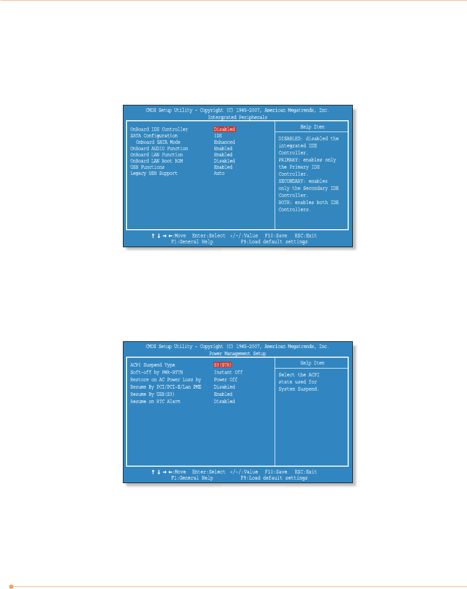
Integrated Peripherals Menu
Sets up options about the chipset built into the main board. Sets up options about the internal
speaker.
Power Management Setup Menu
Sets up options for managing system power.
29
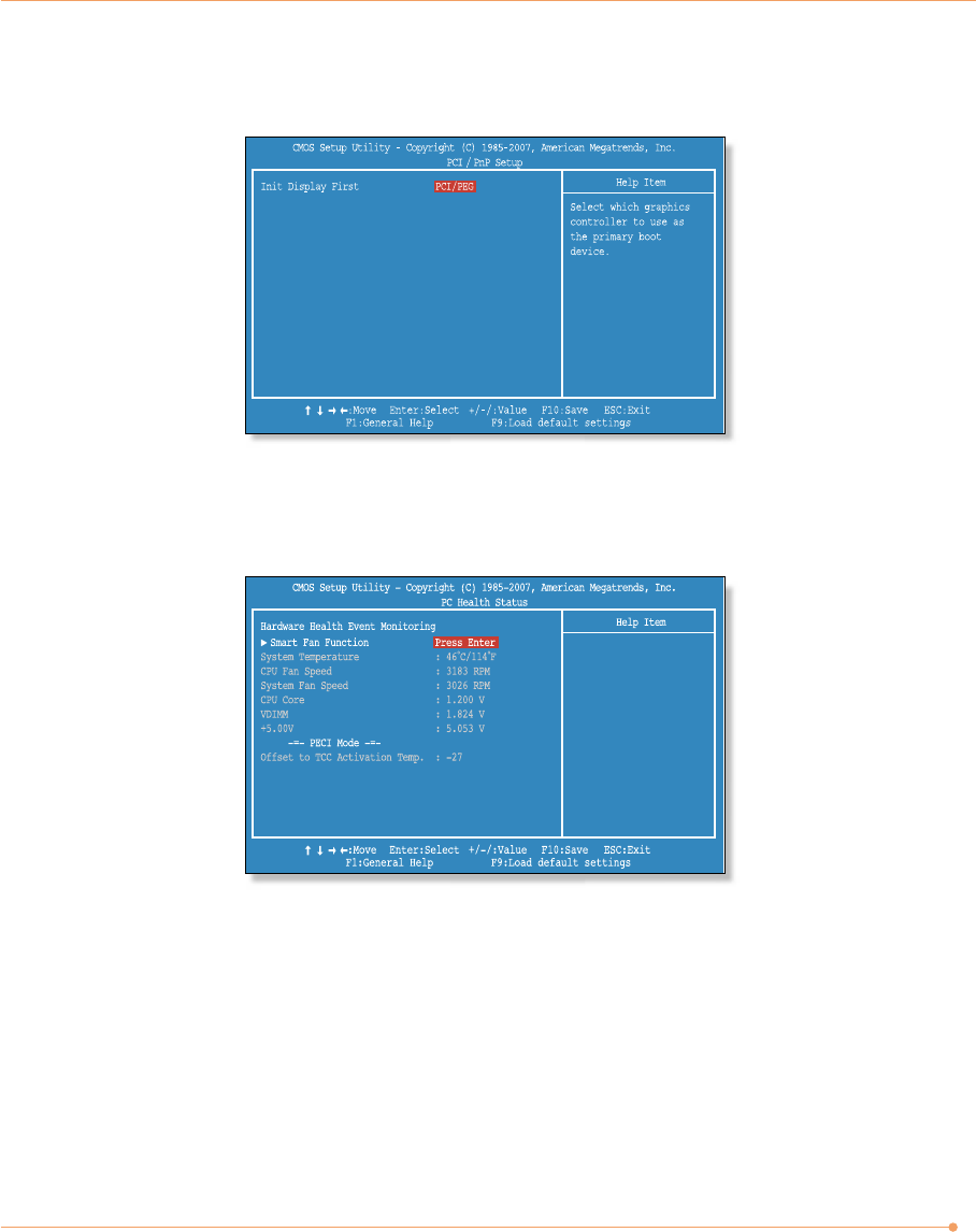
PCI/PnP Setup Menu
PC Health Status Menu
30
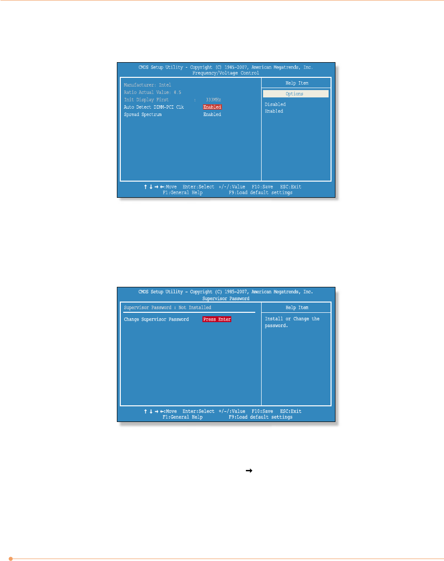
Set up Password
1. On the initial System Setup screen, press < > to go to the Supervisor Password
menu and then press <Enter>.
2. Go to Change Supervisor Password, and then press <Enter>.
Frequency/Voltage Control Menu
Supervisor/User Password Menu
Sets up a password to prevent any unauthorized user from accessing the system.

31
3. On the following screen, enter the password and then press <Enter>.
4. If you entered the correct password, the following window will appear. Press <Enter>.
The Supervisor Password is at a higher level than the User Password.
Then enter the same password again and press <Enter>.
This completes setting up a password.
Enter New Password
Confirm New Password
Password installed
[OK]
Supervisor Password is
Shows the setup status of the Supervisor Password: Installed, if a upervisor Password is set, or
Not Installed.
User Password is
Shows the setup status of the User Password: Installed, if a User Password is set, or Not
Installed.
Change Supervisor Password
Setting up a password helps you prevent unauthorized users from accessing the system. In the
factory settings, no password is installed. A password can have up to six alphanumeric
characters and/or numbers.

Expanding the Main Memory
There may come a time when you want to expand the main memory capacity. When expanding
the main memory,make sure that the specifications of any newly added memory and the
currently installed memory are the same. The following instructions are provided to those who
are familiar with system assembly/disassembly in order to help them to find the memory
specification. If you are not familiar with system assembly/disassembly or do not know your
memory specification, you should not perform the memory upgrade. Please contact customer
support for assistance.
The motherboard has two DIMM sockets, which can accommodate up to 4.0 GB of memory. If
new memory is installed, its type, size and speed are automatically checked by the system
BIOS.
Each of the DIMM sockets supports the following memory specification:
240-pin DDR2 SDRAM Socket, Dual-Channel Support, 667/800 MHz DDR2 SDRAM Memory
Interface.
The appearance of the DIMM memory in the figure may not reflect the actual memory,
depending on the system model.
32
33
1. Before proceeding, make sure that the system is turned off, that you are wearing an anti-
static wrist strap (available in most computer shops), and that your workspace is dust and
smoke-free.
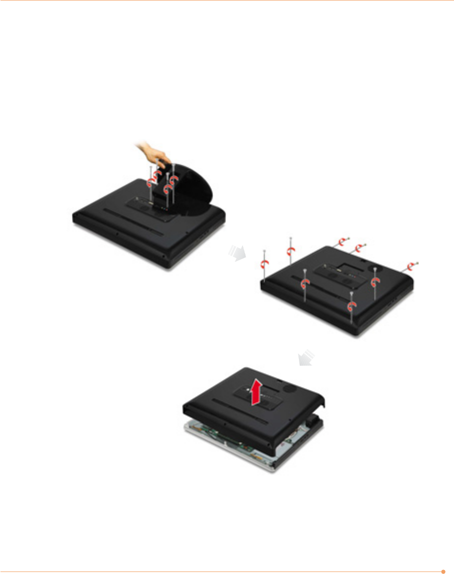
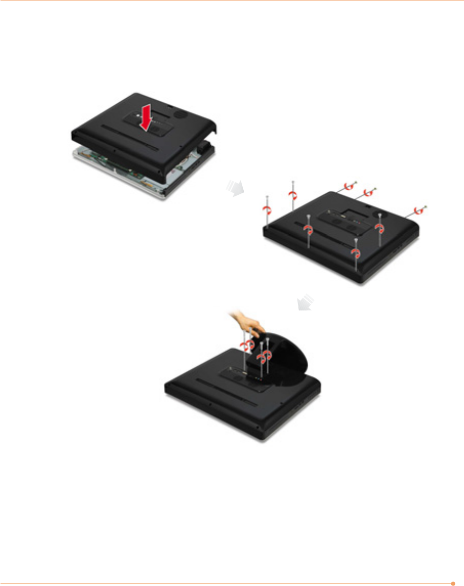
2. Removing the system cover
Place the system on an open flat surface and remove the screws and back cover as shown in
the figure.
Make sure that the LCD panel does
not get damaged.
34
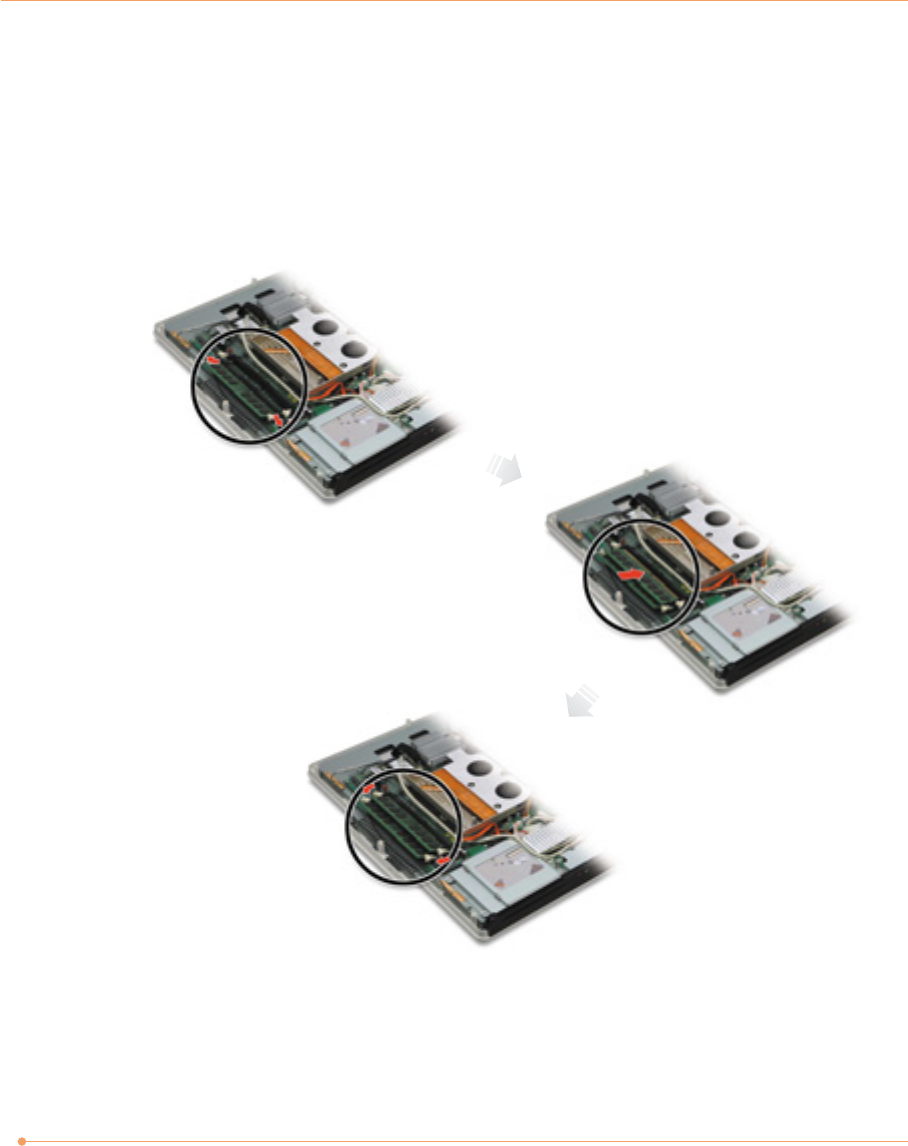
3. Mounting the main memory
If you want to continue to use your existing memory, you will not need to remove it.
1) Make sure that the ejector clips on both sides of the socket are in the open position.
2) Align the notches of the DIMM memory with the slot keys of the socket, this allows the
memory to be inserted. Gently push the memory into the slot until both ejector clips rise
to the lock position.
35
4. Replacing the system cover
Connect the close the back cover and attach the screws. Make sure that the LCD panel does
not get damaged.
5. Checking memory capacity
Once memory installation is complete, restart the system. If an error message related to the
memory capacity appears upon booting, press the Del key to enter the system setup screen.
Save the setting and exit.