TriGem Computer ALL-IN-ONE-SER PC equipped with certified 802.11abg module User Manual Averatec F1 User s Guide US PD
TriGem Computer, Inc PC equipped with certified 802.11abg module Averatec F1 User s Guide US PD
UserManual.wiki
>
TriGem Computer
>
ALL IN ONE SER User Manual
User manual
Navigation menu
Upload a User Manual
Namespaces
Wiki Guide
HTML
PDF
Info
Views
User Manual
Discussion / Help
Navigation


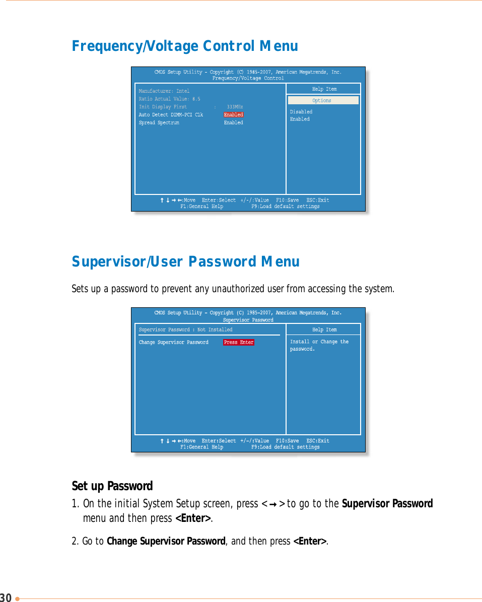
![313. On the following screen, enter the password and then press <Enter>.4. If you entered the correct password, the following window will appear. Press <Enter>.The Supervisor Password is at a higher level than the User Password.Then enter the same password again and press <Enter>.This completes setting up a password.Enter New PasswordConfirm New PasswordPassword installed[OK]Supervisor Password isShows the setup status of the Supervisor Password: Installed, if a upervisor Password is set, orNot Installed. User Password isShows the setup status of the User Password: Installed, if a User Password is set, or NotInstalled.Change Supervisor PasswordSetting up a password helps you prevent unauthorized users from accessing the system. In thefactory settings, no password is installed. A password can have up to six alphanumericcharacters and/or numbers.](https://usermanual.wiki/TriGem-Computer/ALL-IN-ONE-SER/User-Guide-961975-Page-40.png)