Trig Avionics 01629 Licensed Non-Broadcast Aviation Transponder User Manual TT26 ADS B Transponder Installation Manual
Trig Avionics Limited Licensed Non-Broadcast Aviation Transponder TT26 ADS B Transponder Installation Manual
Installation Manual
TT26 ADS-B Transponder
Installation Manual
01633-00-AC
24 January 2017
Trig Avionics Limited
Heriot Watt Research Park
Riccarton, Edinburgh
EH14 4AP
Scotland, UK
Copyright Trig Avionics Limited, 2016
This page intentionally left blank
TT26 ADS-B Transponder Installation Manual 24 January 2017
01633-00 Issue AC
______________________
Trig Avionics Limited i
CONTENTS
1. PREFACE ...............................................................................................4
1.1 PURPOSE ...........................................................................................4
1.2 SCOPE ...............................................................................................4
1.3 CHANGES FROM PREVIOUS ISSUE ......................................................4
1.4 DOCUMENT CROSS REFERENCES ......................................................4
2. INTRODUCTION ..................................................................................5
2.1 TT26 DESCRIPTION ...........................................................................5
2.2 INTERFACES ......................................................................................5
2.2.1 TT26 ADS-B Transponder Unit ...............................................5
3. TECHNICAL SPECIFICATIONS .......................................................7
3.1 TT26 TRANSPONDER UNIT (01629-00) ............................................7
3.2 INSTALLATION APPROVAL .................................................................8
3.3 NON-ETSO FUNCTION ......................................................................8
4. UNIT AND ACCESSORIES SUPPLIED.............................................9
4.1 TT26 ADS-B TRANSPONDER ITEMS .................................................9
4.2 INSTALLATION KIT ............................................................................9
4.3 REQUIRED ITEMS ..............................................................................9
5. INSTALLATION .................................................................................11
5.1 UNPACKING AND INSPECTING EQUIPMENT ......................................11
5.2 TRANSPONDER MOUNTING .............................................................11
5.3 COOLING REQUIREMENTS ...............................................................12
TT26 ADS-B Transponder Installation Manual 24 January 2017
01633-00 Issue AC
______________________
ii Trig Avionics Limited
5.4 TT26 TRANSPONDER ELECTRICAL CONNECTIONS ..........................12
5.4.1 TT26 Interface – Pinout .........................................................13
5.5 TT26 TRANSPONDER INTERFACE DETAILS .....................................14
5.5.1 Power Input ............................................................................14
5.5.2 TMAP Control Port ................................................................14
5.5.3 Auxiliary RS-232 Interface .....................................................15
5.5.4 Auxiliary Power .....................................................................15
5.5.5 Squat Switch Input .................................................................16
5.6 D CONNECTOR CRIMP TERMINALS .................................................16
5.7 WIRING CONSIDERATIONS ...............................................................17
5.8 GPS ANTENNA ................................................................................17
5.9 GPS ANTENNA CABLE ....................................................................17
5.10 TRANSPONDER ANTENNA ...............................................................18
5.11 TRANSPONDER ANTENNA CABLE ....................................................18
5.12 STATIC PRESSURE CONNECTION .....................................................18
6. INSTALLATION SETUP AND TEST ...............................................19
6.1 CORE CONFIGURATION ITEMS .........................................................19
6.1.1 Aircraft Address .....................................................................19
6.1.2 Aircraft Registration ..............................................................19
6.1.3 Aircraft Speed Class ...............................................................19
6.1.4 Aircraft Category ...................................................................19
6.1.5 Squat Switch Source ...............................................................20
6.1.6 Aircraft Length and Width .....................................................20
6.1.7 GPS Antenna Offset ...............................................................20
TT26 ADS-B Transponder Installation Manual 24 January 2017
01633-00 Issue AC
______________________
Trig Avionics Limited iii
6.2 INTERFACE CONFIGURATION ...........................................................20
6.2.1 Altimetry Source .....................................................................20
6.2.2 GPS Source ............................................................................21
7. POST INSTALLATION CHECKS ....................................................22
8. CONTINUED AIRWORTHINESS ....................................................23
9. LIMITED WARRANTY .....................................................................24
10. ENVIRONMENTAL QUALIFICATION FORMS ......................25
11. ADS-B COMPLIANCE ...................................................................27
11.1 ADS-B PARAMETERS SUPPORTED ..................................................27
11.2 FAA 91.227 COMPLIANCE ..............................................................28
11.3 AMC 20-24 COMPLIANCE ...............................................................28
12. INSTALLATION DRAWINGS ......................................................29
12.1 DIRECT CHASSIS MOUNT ................................................................29
12.2 CONNECTOR ARRANGEMENT ..........................................................30
13. BASIC INTERCONNECT DIAGRAM .........................................31
TT26 ADS-B Transponder Installation Manual 24 January 2017
01633-00 Issue AC
______________________
4 Trig Avionics Limited
1. Preface
1.1 Purpose
This manual describes the physical and electrical characteristics and the
installation requirements for a TT26 ADS-B transponder.
1.2 Scope
This document applies to the installation of the TT26 ADS-B Transponder.
At the publication date of this manual the software version identifier for the
TT26 is 1.6 and the FPGA version identifier is 1.5. The software and FPGA
versions are subject to change without notice.
1.3 Changes from Previous Issue
Section 1.4 and 5.5.2: Added document reference for TMAP specification.
Section 3.1: Added C145c class information.
Section 4.1 and 5.2: Removal of quick release tray.
Section 12: Update installation drawings.
1.4 Document Cross References
DEV/TMAP/005
Enhanced TMAP Protocol Specification
Issue 3.0
TT26 ADS-B Transponder Installation Manual 24 January 2017
01633-00 Issue AC
______________________
Trig Avionics Limited 5
2. Introduction
2.1 TT26 Description
The TT26 ADS-B transponder system is an ED-73E compliant Mode S level
2els datalink transponder, with support for ADS-B extended squitter,
elementary surveillance and SI codes, which also meets the relevant
environmental requirements of ED-14G. The TT26 has a nominal power
output of 250 watts, and meets the power output requirements for Class 1.
The TT26 has a built in WAAS GPS receiver which meets the requirements for
DO-229D class Beta1, and provides a position source for ADS-B transmissions
from the transponder. The ADS-B function meets DO-260B class B1S.
The built in pressure sensor provides altitude measurement up to 70,000 feet.
The TT26 is certified to ETSO C10b, ETSO C88b, ETSO C145c, ETSO
C112e and ETSO C166b A2.
The TT26 is controlled using a separate controller; the controller forms part of
the system and is required for full compliance with the altimetry TSO and
transponder TSO.
The TT26 runs from either 14 volt nominal or 28 volt nominal DC power
supply with no configuration changes required.
The TT26 responds to both legacy Mode A/C interrogations and to Mode S
interrogations from both ground radar and airborne collision avoidance
systems. In all cases, the interrogations are received by the TT26 on
1030MHz, and replies are transmitted on 1090MHz.
2.2 Interfaces
2.2.1 TT26 ADS-B Transponder Unit
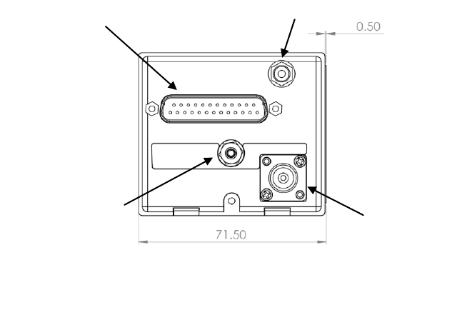
The TT26 has a single TNC antenna connection to a transponder antenna, a
single SMA connector to an active GPS antenna, a single 25 way D-type
TT26 ADS-B Transponder Installation Manual 24 January 2017
01633-00 Issue AC
______________________
6 Trig Avionics Limited
connector and a static pressure connector. The 25 way D-type interface
provides the following services:
Power Input
The TT26 operates on 11 to 33 volts DC.
Controller Datalink
A two wire data link is used to connect the TT26 and the
controller. Depending on TT26 option, this interface can
be provided over a half-duplex RS-485 interface (TMAP
RS-485 bus) or a full duplex RS-232 interface (TMAP
over RS-232).
Second Datalink
A secondary RS-232 interface provides access to GPS
data.
“On ground” input
Allows automatic flight/ground mode switching for
aircraft with a squat switch.

TT26 ADS-B Transponder Installation Manual 24 January 2017
01633-00 Issue AC
______________________
Trig Avionics Limited 7
3. Technical Specifications
3.1 TT26 Transponder Unit (01629-00)
Specification
Characteristics
Compliance
ETSO C112e Class 1 Level 2els, ETSO
C166b A2 Class B1S, ETSO C10b, ETSO
C88b, ETSO C145c Class Beta 1
FCC Identification
VZI01629
Applicable documents
EUROCAE ED-73E, EUROCAE ED-14G
(RTCA DO-160G), RTCA DO-181E, RTCA
DO-260B, AS8003, AS392C, DO-229D
Software
ED-12B (RTCA DO-178B) Level B
Hardware
DO-254 Level C
Power Requirements
11 – 33 volts DC. Typical 8 watts @ 14Volts.
Altitude
70,000 feet
Humidity
Tested to Category A in DO-160G
Operating Temperature
-55°C to +55°C
Transmitter Frequency
1090MHz ± 1MHz
Transmitter Power
250 watts nominal; 125 watts minimum at
antenna after allowing for 0.5dB connector
losses and 1.5dB cable losses.
Transmitter Modulation
8M89 V1D
Receiver Frequency
1030 MHz
Receiver Sensitivity
-74dBm ± 3dB

TT26 ADS-B Transponder Installation Manual 24 January 2017
01633-00 Issue AC
______________________
8 Trig Avionics Limited
Physical Specifications (including connectors)
Height
62 mm (2.44”)
Width
71.5 mm (2.81”)
Length
153 mm (6.02”)
Weight
475 g (1.05 lbs)
3.2 Installation Approval
The conditions and tests required for the TSO approval of the TT26 are
minimum performance standards. It is the responsibility of those desiring to
install this transponder on or within a specific type or class of aircraft to
determine that the aircraft operating conditions are within the TSO standards.
The transponder may be installed only if further evaluation by the user/installer
documents an acceptable installation that is approved by the appropriate
airworthiness authority.
3.3 Non-ETSO Function
The internal altimeter has been qualified to operate at altitudes of up to 70,000
feet. The applicable ETSO certification applies to 50,000 feet. For altitudes
above 50,000 feet the altimeter tolerance extrapolates the allowed value in the
applicable standards; the tolerance at 70,000 feet is not more than 380 feet.

TT26 ADS-B Transponder Installation Manual 24 January 2017
01633-00 Issue AC
______________________
Trig Avionics Limited 9
4. Unit and Accessories supplied
4.1 TT26 ADS-B Transponder Items
The TT26 includes the following items:
Unit Description
Qty
Part Number
TT26 Mode S Transponder
1
01629-00
4.2 Installation Kit
The optional TT26 installation kit includes the following items:
Unit Description
Qty
Part Number
Connector, coaxial TNC
1
00723-00
Headshell, 25 way
1
00726-00
25 way D-type contact housing (female)
1
00866-00
Crimp Terminal, Female, 22-24 AWG
20
00730-00
Hose clip, small
2
00734-00
Connector, coaxial SMA
1
01645-00
4.3 Required Items
Additional items you will require, but which are not in the TT26 package,
include:
Antenna and fixing hardware. The TT26 is compatible with any
transponder antenna approved to ETSO C74 or C112, and any GPS
antenna approved to ETSO or TSO C190.
Cables. You need to supply and fabricate all required cables.
Guidance on cable types is given in section 5 below.
TT26 ADS-B Transponder Installation Manual 24 January 2017
01633-00 Issue AC
______________________
10 Trig Avionics Limited
Fixings. To mount the transponder body directly using the tapped
holes you will need three M4 bolts.
TT26 ADS-B Transponder Installation Manual 24 January 2017
01633-00 Issue AC
______________________
Trig Avionics Limited 11
5. Installation
5.1 Unpacking and Inspecting Equipment
Carefully unpack the transponder and make a visual inspection of the unit for
evidence of any damage incurred during shipment. If the unit is damaged,
notify the shipping company to file a claim for the damage. To justify your
claim, save the original shipping container and all packaging materials.
5.2 Transponder Mounting
The TT26 ADS-B transponder is designed to be mounted in any convenient
location in the cockpit, the cabin, or an avionics bay.
Select a position in the aircraft that is not too close to any high
external heat source.
Avoid sharp bends and placing the cables too near to the aircraft
control cables.
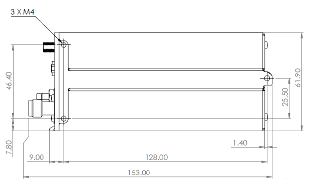
The TT26 transponder is mounted directly to the airframe using bolts into the
three threaded holes in the chassis. Section 12 contains mounting point
positions.
To mount the transponder to the airframe, proceed as follows.
Ensure that the chassis of the TT26 is flush with the mounting surface,
which should be flat, and sufficiently strong to support the
transponder firmly.
Secure the TT26 using three M4 bolts. The bolts should be stainless
steel, or other corrosion proof finish and should be sized so that there
is between 5 mm and 7 mm of thread engagement into the mounting
holes. The bolts must be secured using a thread locking compound,
LOCTITE 242 or equivalent. Torque the bolts to between 1 Nm and
1.5 Nm, taking care not to over tighten.
TT26 ADS-B Transponder Installation Manual 24 January 2017
01633-00 Issue AC
______________________
12 Trig Avionics Limited
5.3 Cooling Requirements
The TT26 ADS-B transponder meets all applicable ETSO requirements
without forced air-cooling.
Attention should however be given to the incorporation of cooling provisions
to limit the maximum operating temperature if the TT26 is installed in close
proximity to other avionics. The reliability of equipment operating in close
proximity in an avionics bay can be degraded if adequate cooling is not
provided.
5.4 TT26 Transponder Electrical Connections
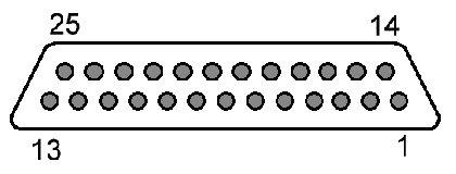
The TT26 has a single 25 way male connector which provides the data and
power inputs to the transponder. A single TNC coaxial connector attaches to
the transponder antenna, and a single SMA connector attaches to the GPS
antenna.

TT26 ADS-B Transponder Installation Manual 24 January 2017
01633-00 Issue AC
______________________
Trig Avionics Limited 13
5.4.1 TT26 Interface – Pinout
Pin
Signal
Direction
1
Ground
-
2
TMAP1A
Bidirectional
3
TMAP1B
Bidirectional
4
Ground
-
5
RS-232 Aux
Input
6
Ground
-
7
RS-232 Aux
Output
8
TMAP2A
Bidirectional
9
TMAP2B
Bidirectional
10
Ground
-
11
Auxiliary Power
Output
12
Ground
-
13
Not Connected
14
Ground
-
15
11-33 VDC
Power Input
16
Reserved
-
17
Not Connected
-
18
Not Connected
-
19
Squat In
Input
20
Not Connected
-
21
Not Connected
-
22
Not Connected
-
23
Not Connected
-
24
RS-232 Control RX
Input
25
RS-232 Control TX
Output
TT26 ADS-B Transponder Installation Manual 24 January 2017
01633-00 Issue AC
______________________
14 Trig Avionics Limited
The following diagram shows the connector orientation as viewed from the
wiring side.
5.5 TT26 Transponder Interface Details
5.5.1 Power Input
The power supply can be 11-33 volts DC; no voltage adjustment is required.
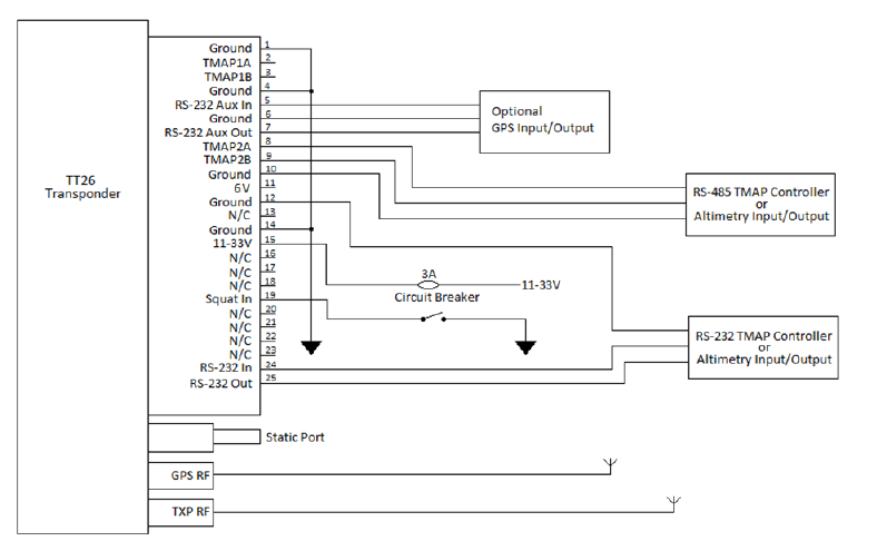
Use a 3 Amp (or greater) circuit breaker for power supply protection to the
TT26.
It is always good practice to use more than one ground wire in an installation.
This is particularly important when the transponder is mounted on a non-
conducting surface, such as a composite structure. With only one wire there
could be only a single grounding path for the transponder, controller and
antenna.
5.5.2 TMAP Control Port
TMAP is a Trig serial protocol that provides a bi-directional interface between
the TT26 and a control system. The protocol is documented in
DEV/TMAP/005 Enhanced TMAP Protocol Specification.
Depending on configuration options the TT26 may be controlled by the TMAP
RS-485 bus on pins 2, 3, 8 and 9, or by TMAP over RS-232 on pins 24 and 25.
Check which option you have before proceeding.
TT26 ADS-B Transponder Installation Manual 24 January 2017
01633-00 Issue AC
______________________
Trig Avionics Limited 15
5.5.2.1 TMAP over RS-485 Bus
Each TMAP RS485 interface comprises a balanced pair of signals, called A
and B, both of which must be connected for communication to work.
There are two sets of TMAP pins on the TT26, TMAP1 A and B, and TMAP2
A and B. This is to support future installation wiring options. The two sets are
identical, and either pair (TMAP1 or TMAP2) may be used to connect to the
control head; you will also need to add a ground wire.
5.5.2.2 TMAP over RS-232
When controlled using RS-232, the controller connects using pins 24, 25 and a
ground wire. The interface is fully compatible with RS-232 signalling levels.
5.5.2.3 Secondary Port
The unused RS-485 or RS-232 interface that is not being used as a control port
will be available for Altimetry input and output. The behaviour of the input
depends on system configuration, defined below. The output always reflects
the current altimetry source, regardless of input configuration.
Note: The TMAP RS-485 interface is optional, and may not be
present on systems using the RS-232 control pair on pins 24 and 25.
5.5.3 Auxiliary RS-232 Interface
The RS-232 interface on pins 5 and 7 is used for GPS data. The GPS can be
configured for either internal or external mode of operation as described in
section 6. The interface is fully compatible with RS-232 signalling levels.
5.5.4 Auxiliary Power
The TT26 provides 6.0 volts on pin 11. This output is intended for diagnostic
use, but can also be used to power small auxiliary equipment or a controller
providing current consumption does not exceed 300 mA.
TT26 ADS-B Transponder Installation Manual 24 January 2017
01633-00 Issue AC
______________________
16 Trig Avionics Limited
5.5.5 Squat Switch Input
The Squat switch input allows the transponder to automatically switch between
Airborne and Ground modes, and affects both the Mode S reply behaviour and
the ADS-B reporting behaviour. The input will be asserted when the voltage to
ground is pulled below approximately 4 volts. The logical sense of the input
can be programmed to be either active low or active high.
On an aircraft with no appropriate squat switch circuit this input should be left
unconnected, and the transponder programmed to ignore the input.
5.6 D Connector Crimp Terminals
The 25 way connector supplied with the TT26 installation kit are MIL standard
versions of the popular sub miniature D type connector family, and use
individual crimp terminals and a receptacle. The MIL specification for this
family of connectors is MIL-C-24308. We supply crimp terminals because
these are more reliable than soldered connections, and are easier to assemble
in-situ in an aircraft, where soldering is impractical. They also allow
individual wires to be removed and replaced in a receptacle without replacing
the whole connector.
The socket contacts used in the 25 way connector conform to MIL part number
M39029/63-368, and are suitable for wire gauges from 20 to 24 AWG.
These contacts are widely used in avionics installation, and there are many
tools available on the market that will reliably crimp them to the wiring.
Because the contacts are a MIL standard, there is also a MIL standard for the
crimp tool, although other proprietary solutions are also available.
The MIL reference for the basic style of hand tool is M22520/2-01. This style
of tool can crimp many different contact types, and relies on interchangeable
"positioners" to hold the actual contact in use. The MIL reference for the
positioner that you need for the crimps we supply is M22520/2-08.
Any tool that complies with these references can be used to crimp these
contacts. One of the most popular vendors of these small hand tools is Daniels
Manufacturing Corporation (see www.dmctools.com). Their AFM8 hand tool
complies with M22520/2-01, and their K13-1 positioner is M22520/2-08

TT26 ADS-B Transponder Installation Manual 24 January 2017
01633-00 Issue AC
______________________
Trig Avionics Limited 17
compliant, so the combination will crimp the supplied connectors.
Once crimped, the contacts should be slotted into the rear of the connector
shell. Push the contact in until the retaining tab clicks into place. Tug gently
to confirm the contact is locked in place.
5.7 Wiring Considerations
The connection from the TT26 transponder to the aircraft and controller uses a
minimum of four (4) signal lines; the TMAP pair and the Power and Ground
pair, although it is good practice to add additional ground wires to the
interface. In a certified installation the normal wire choice would be Tefzel
hook-up wire. Wire of 20 AWG is more than adequate for the task; in
installations where weight is an issue, wire of 22 or 24 AWG can also be used.
Where lighter wires than 20 AWG are used the individual wires should be
laced together for support.
5.8 GPS Antenna
The TT26 is compatible with any GPS antenna approved to ETSO or TSO
C190.
The following table shows recommended antennas.
Antenna Manufacturer
Antenna Model
TSO
Trig Avionics
TA70
TSO-C190
Cobham Antennas
(Comant)
CI 429-200
CI 419-200
TSO-C190
TSO-C190
Sensor Systems Inc
S67-1575-135
S67-1575-145
S67-1575-137
TSO-C190
TSO-C190
TSO-C190
5.9 GPS Antenna Cable
A low loss cable terminating at the TT26 in an SMA connector is required.
The recommended cable is RG400 or RG142. Total cable loss including
TT26 ADS-B Transponder Installation Manual 24 January 2017
01633-00 Issue AC
______________________
18 Trig Avionics Limited
connectors should be less than 10dB.
5.10 Transponder Antenna
The TT26 is compatible with any transponder antenna approved to ETSO or
TSO C74 or C112.
5.11 Transponder Antenna Cable
A low loss cable terminating at the transponder in a TNC connector is required.
The TT26 is designed to meet Class 1 requirements with an allowance of 2 dB
for loss in the connectors and cable used to connect it to the antenna.
Excessive loss will degrade both transmitter output power and receiver
sensitivity.
Allowing 0.25dB loss for the connector at each end of the antenna cable
assembly leaves an allowance of 1.5dB maximum loss for the cable itself. An
acceptable cable:
Has less than 1.5dB loss for the run length needed
Has a characteristic impedance of 50 Ohms
Has double braid screens or has a foil and braid screen
For cable runs of less than 2.5 metres, RG400 is a good choice.
5.12 Static Pressure Connection
The TT26 includes an altitude encoder which must be connected to the same
source of static pressure as the primary altimeter on the aircraft. The TT26
static pressure port provides a mounting spigot intended for nominal 3mm or
1/8 inch inside diameter tubing.
In all cases, the static line should include drainage provisions and should be
routed in accordance with CS 23.1325 or other applicable airworthiness
provisions for the aircraft.
TT26 ADS-B Transponder Installation Manual 24 January 2017
01633-00 Issue AC
______________________
Trig Avionics Limited 19
6. Installation Setup and Test
The system controller uses the TMAP protocol to provide important system
parameters to the TT26, including the Mode S address. The following items
should be configured in the system controller.
6.1 Core Configuration Items
6.1.1 Aircraft Address
The Mode S Address is a 24 bit number issued to the aircraft by the
registration authority for the aircraft. These addresses are usually written as a 6
digit hexadecimal number, although you may also encounter one written as an
8 digit octal number.
6.1.2 Aircraft Registration
The aircraft registration is the unique alphanumeric string that identifies the
aircraft. It used as the default flight ID.
6.1.3 Aircraft Speed Class
Mode S transponders can transmit their maximum airspeed characteristics to
aircraft equipped with TCAS. This information is used to help identify threats
and to plan avoiding action by the TCAS equipped aircraft. The airspeeds are
grouped in ranges; select the range that corresponds to the aircraft.
6.1.4 Aircraft Category
To assist ATC tracking of aircraft, an aircraft category can be transmitted by
Mode S transponders. Select the aircraft category that most closely matches
the aircraft in which the TT26 is installed.
TT26 ADS-B Transponder Installation Manual 24 January 2017
01633-00 Issue AC
______________________
20 Trig Avionics Limited
6.1.5 Squat Switch Source
The Squat switch input allows the TT26 to automatically switch between
Airborne and Ground modes. If the squat switch input is not connected the
“Ignore Squat Switch” option must be selected.
6.1.6 Aircraft Length and Width
On the ground, ADS-B transmits encoded aircraft size information which is
used by ATC to identify taxiing routes and potential conflicts. The aircraft
length and width (wingspan) should be configured.
6.1.7 GPS Antenna Offset
The GPS antenna offset is used together with the aircraft length and width to
manage taxiway conflicts. A typical GPS installation does not report the
geographic position of the centre of the aircraft, or even the tip of the nose of
the aircraft; instead it usually reports the location of the actual GPS antenna
(not the GPS receiver). In normal flight operations this distinction is of no
practical importance at all, but if ADS-B is used to manage taxiway conflicts, a
significant offset in antenna position could mean that the aircraft is not in the
same place as the ADS-B reported position. Although primarily intended for
position correction on large transport aircraft, General Aviation aircraft can
also have a significant offset. For example, if the aircraft has a long tail boom
and the GPS antenna is on the top of the tail, the GPS position could be 4
metres or more from the nose of the aircraft.
Enter the position of the GPS antenna relative to the nose of the aircraft. The
position is stored and transmitted to the nearest 2 metres; great accuracy in
measurement is not required.
6.2 Interface Configuration
6.2.1 Altimetry Source
The transponder has an internal altimeter, and that is the primary source for
altimetry. The system can also be configured to use an external air data
TT26 ADS-B Transponder Installation Manual 24 January 2017
01633-00 Issue AC
______________________
Trig Avionics Limited 21
computer, or to receive the altimetry data over the link from the controller.
In all three cases the altimetry data will be transmitted from the secondary data
output (either RS232 or RS485, depending on which port is the control port).
This output uses Shadin S format messages at 9600 bps. Only the D, a and b
records are provided, as well as the Shadin checksum.
If the system is configured to use external air data, the input protocol expected
is also Shadin S format.
6.2.2 GPS Source
The transponder has an internal GPS receiver, and that is the primary position
source for ADS-B operation. The GPS data is routed internally to the
transponder and is also transmitted on the auxiliary serial port (pin 7).
The internal GPS can be disabled and an external position source used. In this
case the data input is read from the auxiliary serial input (pin 5); the output on
pin 7 is disabled.
The GPS I/O uses Accord legacy protocol. This protocol is detailed in ES-
GPSBL, “NexNav Mini Nominal Technical Description”.
TT26 ADS-B Transponder Installation Manual 24 January 2017
01633-00 Issue AC
______________________
22 Trig Avionics Limited
7. Post Installation Checks
Post installation checks should be carried out in accordance with your
certification requirements. These checks should include:
Mode S interrogations to verify correct address programming.
Verification of the reported altitude using a static tester.
Where installed, verification of correct squat switch ground/airborne
indications.
Interrogations to verify the receiver sensitivity. A Mode S
transponder should have a minimum triggering level (MTL) of
between -77 dBm and -71 dBm. Failure to meet this requirement
usually indicates antenna or coaxial cable problems.
Interrogations to verify the transmitted power. The installation should
have no less than 125 watts at the antenna (and no more than 500
watts). Failure to meet this requirement is also generally due to
antenna or wiring issues.
Verification of the GPS position source and ADS-B outputs.
Whenever a valid position is received by the transponder and the
transponder is in any mode other than Standby, ADS-B Extended
Squitters should be observed on the transponder test set.
TT26 ADS-B Transponder Installation Manual 24 January 2017
01633-00 Issue AC
______________________
Trig Avionics Limited 23
8. Continued Airworthiness
Other than for periodic functional checks required by the regulations, the TT26
ADS-B transponder has been designed and manufactured to allow “on
condition maintenance”. This means that there are no periodic service
requirements necessary to maintain continued airworthiness, and no
maintenance is required until the equipment does not properly perform its
intended function. When service is required, a complete performance test
should be accomplished following any repair action. Repairs should only be
carried out in accordance with Trig Avionics Limited service procedures.
TT26 ADS-B Transponder Installation Manual 24 January 2017
01633-00 Issue AC
______________________
24 Trig Avionics Limited
9. Limited Warranty
Trig Avionics Limited warrants our products to be free from defects in
materials and workmanship for a period of six (6) months from the date of
installation by an authorised dealer.
This warranty covers repair and/or replacement at our option, of any parts
found to be defective, provided such defects in our opinion are due to faulty
material or workmanship and are not caused by tampering, abuse, or normal
wear.
All warranties are F.O.B.
Trig Avionics Limited
Heriot Watt Research Park
Riccarton, Currie, EH14 4AP
Trig Avionics will not accept or pay for any charges for warranty work
performed outside our factory without prior written consent.
This warranty applies only to products in normal use. It does not apply to units
or circuit boards defective due to improper installation, physical damage,
tampering, lightning or other electrical discharge, units with altered serial
numbers, or units repaired by unauthorised persons or in violation of Trig
Avionics Limited service procedures.
Trig Avionics Limited assumes no responsibility for any consequential losses
of any nature with respect to any products or services sold, rendered, or
delivered.

TT26 ADS-B Transponder Installation Manual 24 January 2017
01633-00 Issue AC
______________________
Trig Avionics Limited 25
10. Environmental Qualification Forms
Nomenclature:
TT26 ADS-B Transponder
Part Number:
01629-00-(xx)
ETSO:
C112e, C166b, C10b, C88b, C145c
Manufacturer:
Trig Avionics Limited
Address:
Heriot Watt Research Park, Riccarton, Currie, Scotland,
EH14 4AP
Conditions
DO-160G
Section
Description of Conducted Tests
Temperature and Altitude
4.0
Category E1
Low temperature ground
survival
4.5.1
-55°C
Low temperature short-
time operating
4.5.1
-55°C
Low temperature
operating
4.5.2
-55°C
High temperature
operating
4.5.4
+55°C
High temperature short-
time operating
4.5.3
+55°C
High temperature ground
survival
4.5.3
+85°C
Loss of Cooling
4.5.5
Cooling air not required (+55°C operating
without cooling air)
Altitude
4.6.1
70,000 feet
Decompression
4.6.2
N/A
Overpressure
4.6.3
N/A
Temperature Variation
5.0
Equipment tested to Category B
Humidity
6.0
Equipment tested to Category A
Operational Shocks
7.2
Equipment tested to Category B

TT26 ADS-B Transponder Installation Manual 24 January 2017
01633-00 Issue AC
______________________
26 Trig Avionics Limited
Crash Safety
7.3
Equipment tested to Category B type 5
Vibration
8.0
Aircraft zone 2; type 3, 4, 5 to category S
level M, type 1 (Helicopters) to category U
level G
Explosion
9.0
Equipment identified as Category X – no test
required
Waterproofness
10.0
Equipment identified as Category X – no test
required
Fluids Susceptibility
11.0
Equipment identified as Category X – no test
required
Sand and Dust
12.0
Equipment identified as Category X – no test
required
Fungus
13.0
Equipment identified as Category X – no test
required
Salt Spray
14.0
Equipment identified as Category X – no test
required
Magnetic Effect
15.0
Equipment tested to Category Z, 0.3m
Power Input
16.0
Equipment tested to Category BXX
Voltage Spike
17.0
Equipment tested to Category B
Audio frequency
conducted susceptibility
18.0
Equipment tested to Category B
Induced signal
susceptibility
19.0
Equipment tested to Category AC
Radio frequency
susceptibility
20.0
Equipment tested to Category TT
Radio frequency emission
21.0
Equipment tested to Category B
Lightning induced
transient susceptibility
22.0
Equipment tested to Category B2H2L2
Lightning direct effects
23.0
Equipment identified as Category X – no test
required
Icing
24.0
Equipment identified as Category X – no test
required
Electrostatic Discharge
25.0
Equipment tested to Category A
Fire, Flammability
26.0
Equipment identified as Category C
TT26 ADS-B Transponder Installation Manual 24 January 2017
01633-00 Issue AC
______________________
Trig Avionics Limited 27
11. ADS-B Compliance
TT26 ADS-B transponders include support for Extended Squitter ADS-B out.
The TT26 is a DO-260B compliant broadcast participant.
11.1 ADS-B Parameters Supported
The following table summarises the ADS-B parameters that are transmitted by
the TT26.
Parameter
BDS Register
SPI
0,5
Emergency Indicator
0,5
Barometric Altitude
0,5
Quality Indicator (NIC)
0,5
Airborne Position
Latitude
0,5
Longitude
0,5
Quality Indicator (NIC)
0,6
Surface Position
Latitude
0,6
Longitude
0,6
Surface Ground Speed
0,6
Surface Ground Track
0,6
Aircraft Identification
0,8
Airborne Ground Velocity
0,9
Geometric to Barometric altitude difference
0,9
Geometric Vertical Rate
0,9
Squawk Code
6,1

TT26 ADS-B Transponder Installation Manual 24 January 2017
01633-00 Issue AC
______________________
28 Trig Avionics Limited
Emergency Status
6,1
Quality Indicator (NACp)
6,5
Quality Indicator (NACv)
6,5
Quality Indicator (SIL)
6,5
Version Indicator
6,5
Surface Length/Width
6,5
Surface Antenna Offset
6,5
In all cases, uncompensated latency due to the transponder and internal GPS is
less than 150 milliseconds.
11.2 FAA 91.227 Compliance
A TT26 can form the basis of 14 CFR 91.227 compliant ADS-B installation.
For installations seeking certification to 91.227 or other applicable standards,
additional compliance information is available on request from Trig Avionics
Limited.
11.3 AMC 20-24 Compliance
A TT26 can form the basis of an AMC 20-24 compliant ADS-B installation.
For installations seeking certification to AMC20-24 or other applicable
standards, additional compliance information is available on request from Trig
Avionics Limited.
TT26 ADS-B Transponder Installation Manual 24 January 2017
01633-00 Issue AC
______________________
Trig Avionics Limited 29
12. Installation Drawings
12.1 Direct Chassis Mount
All dimensions in millimetres
TT26 ADS-B Transponder Installation Manual 24 January 2017
01633-00 Issue AC
______________________
30 Trig Avionics Limited
12.2 Connector Arrangement
GPS Antenna
Transponder
Antenna
TT26 Interface
Static Pressure
Connection
All dimensions in millimetres
TT26 ADS-B Transponder Installation Manual 24 January 2017
01633-00 Issue AC
______________________
Trig Avionics Limited Page 31
13. Basic Interconnect Diagram
TT26 ADS-B Transponder Installation Manual 24 January 2017
01633-00 Issue AC
______________________
Page 32 Trig Avionics Limited
This page intentionally left blank