Trilithic EASYCAP-1 Emergency Alert System User Manual
Trilithic, Inc. Emergency Alert System Users Manual
Users Manual
DRAFT
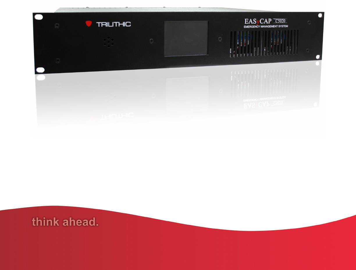
EASyCAP
Encoder/Decoder
Operation Manual
DRAFT

DRAFT
EASyCAP Encoder/Decoder - Manual
1
Trilithic Company Profile
Trilithic is a privately held manufacturer founded in 1986 as an engineering and assembly
company that builds and designs customer-directed products for telecommunications, military,
and industrial customers. From its modest beginnings as a two-man engineering team, Trilithic
has grown over the years and broadened its offerings of RF and microwave components by
adding broadband solutions to its product line. This was accomplished with the acquisition of
components manufacturer Cir-Q-Tel and instruments manufacturer Texscan.
Today, Trilithic is an industry leader, providing telecommunications solutions for major broadband,
RF and microwave markets around the world. As an ISO 9000:2001 certified company with over
40 years of collective expertise in engineering and custom assembly, Trilithic is dedicated to
providing quality products, services and communications solutions that exceed customer
expectations.
Trilithic is comprised of five major divisions:
Broadband Instruments and Systems
Offers test, analysis, and quality management solutions for the major cable television
systems worldwide.
RF Microwave Components
Provides components and custom subsystems for companies specializing in cellular,
military, and other wireless applications.
Emergency Alert Systems
Leading supplier of government-mandated emergency alert systems used by broadcast
TV, cable TV, IPTV, DBS, and radio stations.
XFTP
Offers a specialty line of field technical products for cable operators and technicians, as
well as a line of products for installing electronics in the home of the future.

DRAFT
EASyCAP Encoder/Decoder - Manual
2
THIS PAGE LEFT INTENTIONALLY BLANK

DRAFT
EASyCAP Encoder/Decoder - Manual
3
1. General Information .............................................................................................................. 5
Introduction ............................................................................................................................ 5
FCC Certification................................................................................................................... 6
Unpacking and Inspection ...................................................................................................... 6
Claims for Damage in Shipment ............................................................................................ 6
Helpful Website ..................................................................................................................... 7
Where to Get Technical Support ............................................................................................. 7
How this Manual is Organized ................................................................................................ 8
Conventions Used in this Manual ........................................................................................... 8
2. Overview ............................................................................................................................... 9
Wiring Recommendations ...................................................................................................... 9
Hardware Overview .............................................................................................................10
Front Panel View ............................................................................................................10
Rear Panel View ............................................................................................................ 11
Rear Panel Details .........................................................................................................15
3. Configuration ...................................................................................................................... 19
System Login ....................................................................................................................... 19
Network Settings .................................................................................................................20
Network Interfaces .......................................................................................................... 20
Network Time Protocol (NTP) Encoder/Decoder .............................................................22
Date/Time Settings ..............................................................................................................23
CAP Settings.......................................................................................................................24
TCP Feed Settings ........................................................................................................ 25
Alert Text Settings ................................................................................................................26
Accepted Events .................................................................................................................27
Accepted Locations ............................................................................................................. 28
Outgoing Delivery Settings ...................................................................................................29
Encoder/Decoder Settings .............................................................................................30
User Account Settings .......................................................................................................... 31
User Settings .................................................................................................................32
System Administration Settings ........................................................................................... 33
Upgrades ....................................................................................................................... 33
Reboot ........................................................................................................................... 34
Logs .................................................................................................................................... 35
Alert Log ........................................................................................................................ 35
System Log .................................................................................................................... 35
About ................................................................................................................................... 36
Table of Contents

DRAFT
EASyCAP Encoder/Decoder - Manual
4
4. Appendix ............................................................................................................................. 37
Specifications ...................................................................................................................... 37
General Specifications ................................................................................................... 37
Processor and Memory .................................................................................................. 37
Chassis .......................................................................................................................... 37
Communications ............................................................................................................ 37
Audio ............................................................................................................................. 37
Video ............................................................................................................................. 38
General Purpose Inputs and Outputs ............................................................................... 38
Radio Receiver Boards .................................................................................................. 38
AES-EBU Digital Audio Board ....................................................................................... 38
Communications Board .................................................................................................. 38
PCI-Express Expansion Slot (Optional) .......................................................................... 39
Trilithic EAS 2-Year Limited Warranty ................................................................................... 40

DRAFT
EASyCAP Encoder/Decoder - Manual
5
1. General Information
Chapter 1
Introduction
The Trilithic EASyCAP (Model EASyCAP-1) EAS (Emergency Alert System) Encoder/Decoder is
a two-U rack mounted control center capable of performing manual or automated EAS messaging
for Cable, Broadcast, and Wireline systems, in accordance with CFR 47 part 11 FCC regulations,
and the EAS Cable Handbook.
The EASyCAP receives EAS messages from up to six audio sources (internal or external),
decodes the FSK EAS message, and operates the target system equipment to replay the
message for viewers/listeners. In addition, messages can be originated by the user via local or
remote control of the EASyCAP. The EAS Audio sources for the EASyCAP include internal AM/
FM/NOAA radios and external audio inputs that can be connected to any known EAS audio
source. EAS Audio is decoded by the internal AFSK circuitry, it is then sorted and interpreted to
determine the type of emergency or test, locations for which the emergency applies, and other
information supplied in the EAS Header. If a voice message is contained in the EAS message, it
is recorded for possible playback to subscribers. EAS messages then pass through a series of
tests to determine if the message matches predefined, user configurable parameters. If these
tests pass, EAS activation (message playback) to the system occurs. To play an EAS message to
viewers/listeners, the EASyCAP activates TTLs, Contact Closures, RS-485 data commands, RS-
232 data commands, and several IP based protocols, it also supplies pertinent video and re-
encodes/plays the EAS FSK and recorded audio. The TTLs, Contact Closures, and serial data
commands, and IP protocols activate routing equipment and end-user devices to provide the
emergency audio and video to all viewers/listeners.
In addition to the EAS messaging capabilities, the EASyCAP records all received and
transmitted messages in its internal log for later retrieval.

DRAFT
EASyCAP Encoder/Decoder - Manual
6
FCC Certification
The Trilithic EASyCAP Encoder/Decoder is certified to comply with 47 CFR, Part
11 (FCC regulations) for EAS encoders and decoders, and is registered with the
FCC under identification number: P4V-EASYCAP-1.
Persuant to FCC 15.21 of the FCC rules, changes not expressly approved by
Trilithic, Inc. might cause harmful interference and void the FCC authorization to
operate this product.
This equipment has been tested and found to comply with the limits for a Class A digital device,
pursuant to Part 15 of the FCC Rules. These limits are designed to provide reasonable protection
against harmful interference in a residential installation. This equipment generates, uses and can
radiate radio frequency energy and, if not installed and used in accordance with the instructions,
may cause harmful interference to radio communications. However, there is no guarantee that
interference will not occur in a particular installation. If this equipment does cause harmful
interference to radio or television reception, which can be determined by turning the equipment off
and on, the user is encouraged to try to correct the interference by one or more of the following
measures:
Reorient or relocate the receiving antenna.
Increase the separation between the equipment and receiver.
Connect the equipment into an output on a circuit different from that to which thereceiver is
connected.
Consult the dealer or an experienced radio/TV technician for help.
Unpacking and Inspection
When the EASyCAP Encoder/Decoder arrives, immediately inspect the shipping container and
contents for visible damage. Keep all packing materials until the equipments intended
performance characteristics have been verified. If any of the equipment is damaged or fails to
operate properly due to transportation damage, immediately file a claim with the transportation
company or, if insured separately, with the insurance company.
Each EASyCAP Encoder/Decoder will arrive in its own shipping container. The container will, at
a minimum, include the following components; EASyCAP Encoder/Decoder & AC Power Cord.
Claims for Damage in Shipment
Claims for shipping damage should be directed to the shipping and/or freight delivery service
used. Claims should be made within 7 days to insure prompt handling of the claim.

DRAFT
EASyCAP Encoder/Decoder - Manual
7
Helpful Website
The following website contains general information which may be of interest:
http://www.trilithic.com
Trilithics website contains product specifications and information, tips, release information,
marketing information, Frequently Asked Questions (FAQs), bulletins, and other technical
information. This website can be referenced for product updates.
Where to Get Technical Support
Trilithic technical support is available Monday through Friday from 8:00AM to 5:00PM EST.
Callers in North America can dial 1-317-895-3600 or 1-800-344-2412 (toll free). International
callers should dial 1-317-895-3600 or fax questions to 1-317-895-3613. You can also e-mail
technical support at EASysupport@trilithic.com.
For quicker support response when calling or sending e-mail, please provide the following
information:
Your name and your company name
The technical point of contact (name, phone number, e-mail)
The serial number of the EASyCAP Encoder/Decoder
A detailed description of the problem you are having, including any error or information
messages
Before any Trilithic EAS encoder/decoder can be returned for repair, Trilithic will issue a return
material authorization (RMA) number. NO RETURNED EQUIPMENT WILL BE ACCEPTED
WHICH DOES NOT HAVE AN RMA NUMBER PROMINENTLY DISPLAYED ON THE OUTSIDE
SHIPPING CARTON AND ON THE SHIPPING LABEL. A complete and full description, in writing,
regarding the service issues with the equipment must be supplied inside the shipping container
with each piece of equipment for which an RMA number has been issued.
Hardware or software modifications and changes may occur at any
time during production, shipping, and/or during the equipments life
span. These changes may occur or be implemented by Trilithic,
Inc. without prior written notice or warning.
DRAFT
EASyCAP Encoder/Decoder - Manual
8
Conventions Used in this Manual
This manual has several standard conventions for presenting information.
Connections, menus, menu options, and user entered text and commands appear in bold.
Section names, web, and e-mail addresses appear in italics.
A NOTE is information that will be of assistance to you related
to the current step or procedure.
A CAUTION alerts you to any condition that could cause a
mechanical failure or potential loss of data.
A WARNING alerts you to any condition that could cause
personal injury.
How this Manual is Organized
This manual is divided into the following chapters:
Chapter 1, General Information, provides Trilithic contact information and describes how
this operation manual is structured.
Chapter 2, Overview gives an overview of the EASyCAP Encoder/Decoder hardware
and how it works.
Chapter 3, Configuration describes the steps necessary to configure the EASyCAP
Encoder/Decoder.
Chapter 3, Appendix describes the specifications and warranty of the EASyCAP
Encoder/Decoder.

DRAFT
EASyCAP Encoder/Decoder - Manual
9
2. Overview
Chapter 2
Wiring Recommendations
Shielded audio wire for all TTL, contact closure, and audio connections
Shielded RS-232 and printer cables
Shielded (coaxial) video cables
Shielded RS-485 data cable
Shielded Category 6 or 7 Ethernet cables for all Ethernet connections.
DRAFT
EASyCAP Encoder/Decoder - Manual
10
21
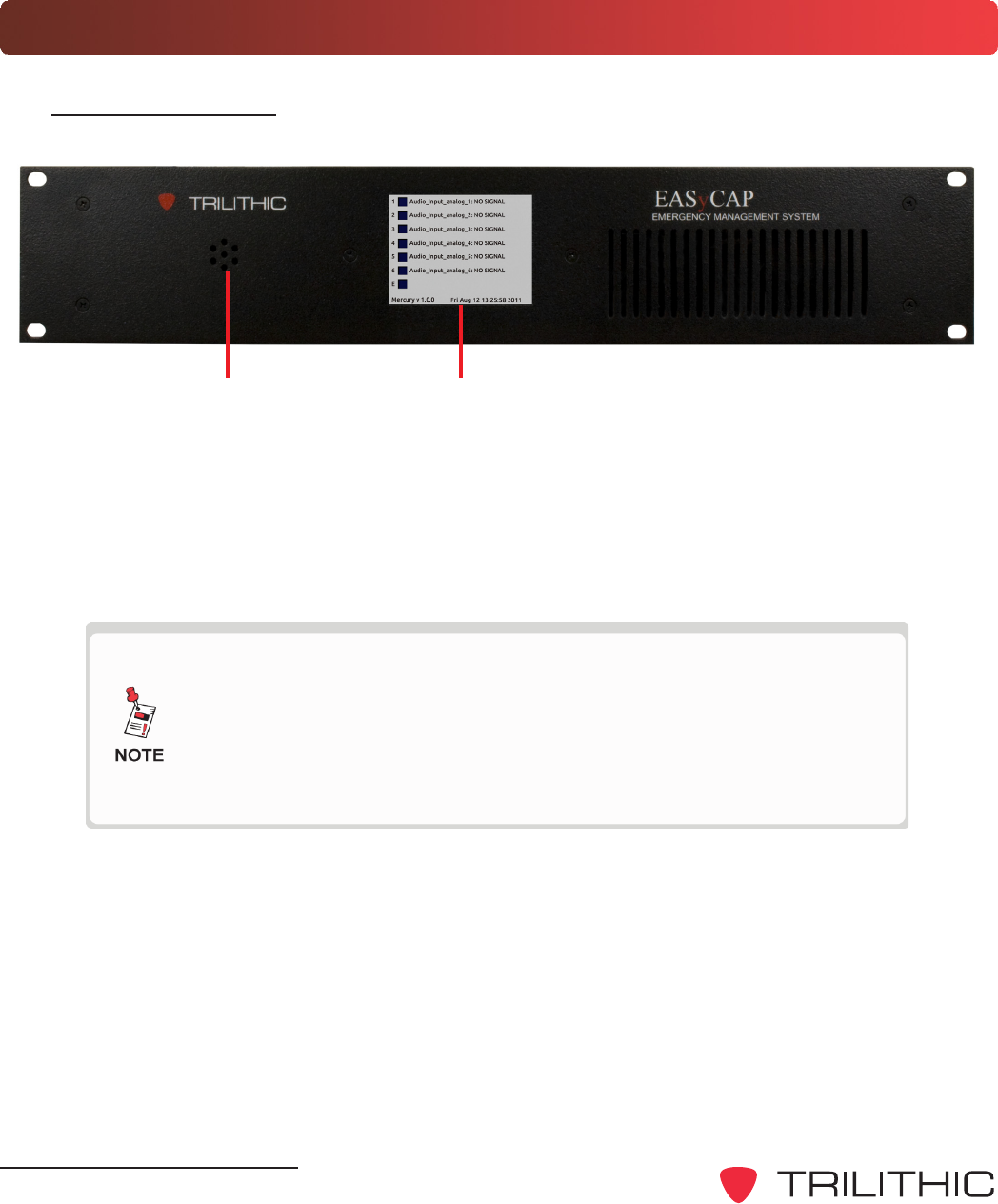
Hardware Overview
Front Panel View
1. Speaker - Used for monitoring audio inputs and to provide aural feedback during EAS
activations.
2. Touchscreen LCD display - Provides visual feedback during programming, setup,
monitoring, and activations and it is used for local control of the EASyCAP and access
to the on-board menu system.
The keypad and LCD display provide an on-board menu system,
allowing for a limited amount of configuration, tests, and
encoding functions. A secure web interface provides more
comprehensive configuration and control of the encoder/
decoder.
DRAFT
EASyCAP Encoder/Decoder - Manual
11
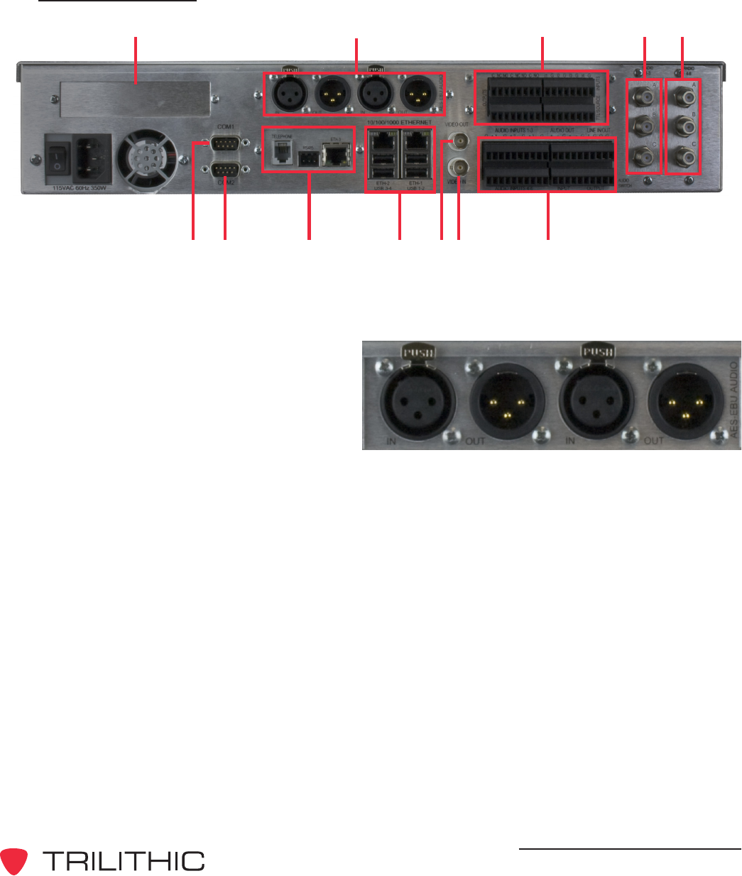
Rear Panel View
345
91078 11 1312
2
1
1. PCIe Expansion Slot (Optional) - This is a PCIe expansion slot that will accomodate
a 1, 4, or 16 lane PCIe card. This is reserved for future use.
2. AES-EBU Digital Audio - This is
an AES-EBU expansion slot that
accomodates two AES-EBU
digital audio switches. Each switch
provides a pair of channels using
110 Ohm XLR connections. Each
switch provides a pair of channels
using 110 Ohm XLR connections. Internal switches are provided to replace the AES-
EBU program audio with alert audio. Alert audio automatically locks to the incoming bit
rate and sample rate (up to 192 kHz). Configurable as a switch or an audio source.
DRAFT
EASyCAP Encoder/Decoder - Manual
12
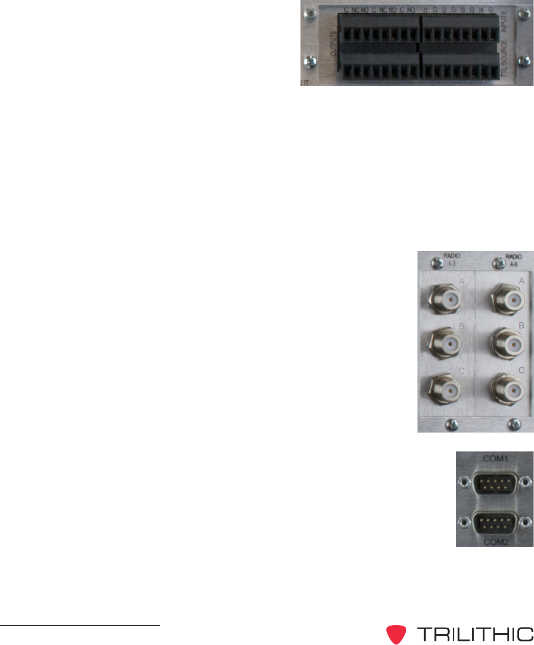
3. General Purpose Inputs/Outputs - The
EASyCAP Encoder/Decoder comes with
six (6) general purpose outputs, four (4)
general purpose inputs, and two (2) TTL
outputs:
General Purpose Outputs - This
provides a programmable contact
closure output (switch) used to activate equipment to route EAS message audio
and video, sound alarms, etc. during EAS activations.
General Purpose Inputs - This provides a means for operators or external
automation equipment to trigger or abort events (such as message
retransmission) within the EASyCAP.
TTL Outputs - These provide a five (5) volt DC signal (and ground connection)
used to activate EAS audio and video routing equipment. A current source is
also provided.
4. Radios 1-3 - This is an AM/FM/NOAA radio receiver board with
three radio tuners (A, B, and C) per board.
5. Radios 4-6 - This is an AM/FM/NOAA radio receiver board with
three radio tuners (A, B, and C) per board.
6. COM1 - (RS-232 Connection) Provides an RS-232 compliant serial
data connection to provide streaming EAS information to external
character generators, as well as to provide a serial input/output for the
EASyCAP.
7. COM2 - (RS-232 Connection) Provides an RS-232 compliant serial
data connection to provide streaming EAS information to external
character generators, as well as to provide a serial input/output for the
EASyCAP.
DRAFT
EASyCAP Encoder/Decoder - Manual
13
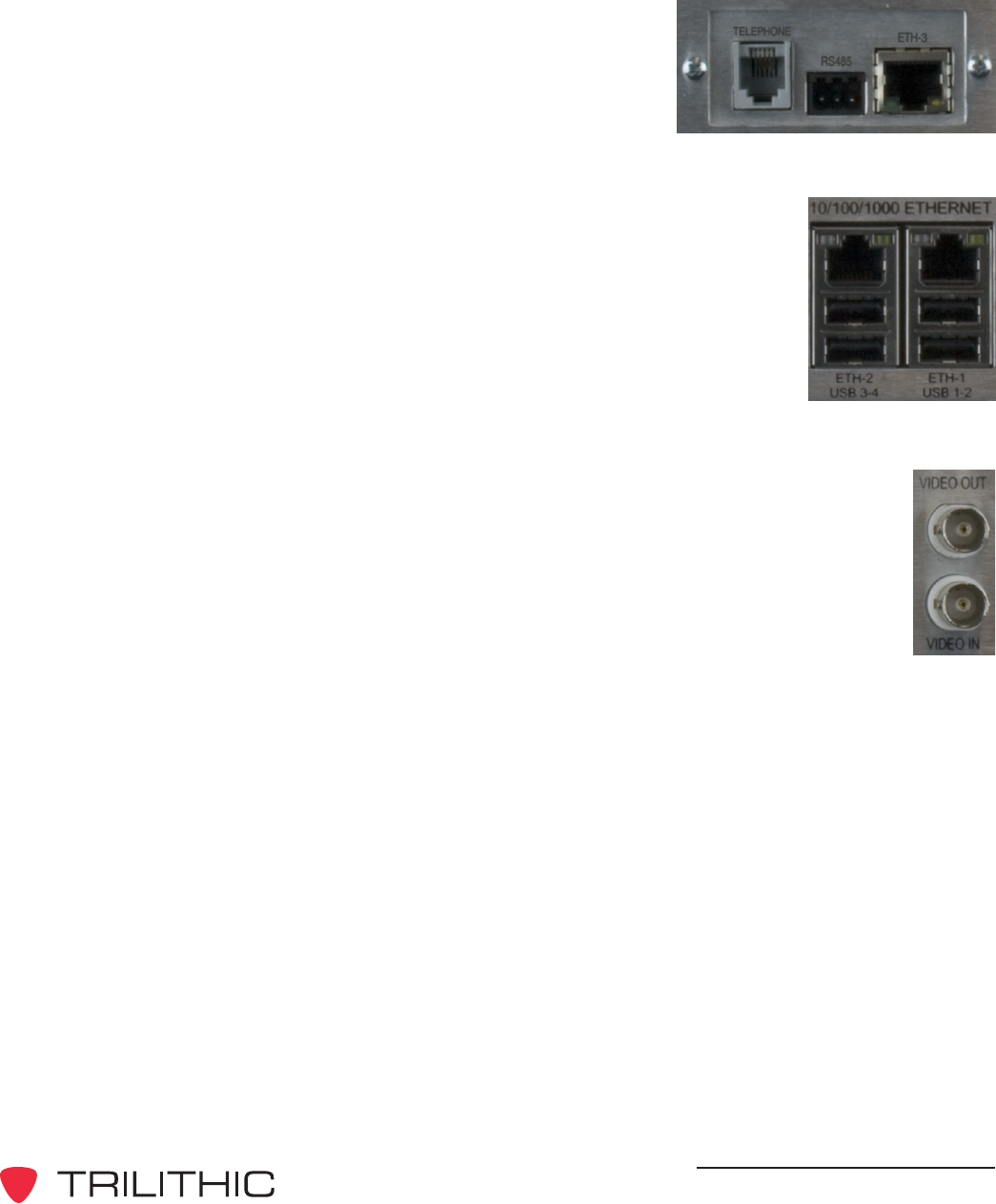
8. Communications Board - This is a communications
board that is equipped with the following:
One 10/100 Ethernet Port
One Telephone Modem Port
One RS-485 Port
9. Ethernet - Two 10/100/1000 Ethernet Ports. Provides an Ethernet
interface for remote configuration, operation, and maintenance of
the EASyCAP, as well as providing digital EAS messages across a
network to a stations audio and video equipment and allowing
distant monitoring stations to be transported over Ethernet to the
EASyCAP.
USB Ports - Four USB ports are provided for USB communication.
10. CG VIDEO IN - NTSC video input connection (normal station video) for the
character generator.
11. CG VIDEO OUT - NTSC video output connection (EAS modified station
video) to the transmitter.

DRAFT
EASyCAP Encoder/Decoder - Manual
14
12. Audio Interface Board - This provides six
(6) balanced 600 Ohm audio inputs, one
(1) line input, one (1) line output, two (2)
EAS audio outputs, one (1) program audio
input, and one (1) program audio output.
Audio Inputs 1-6 - This provides a
means for connecting up to six (6)
external audio sources for EAS
monitoring, or for supplying audio for transmission.
Audio Outputs & Line Output - This provides EAS audio outputs that may be
distributed for EAS messaging and monitoring.
Line Input - This provides a connection for a line-level microphone input for
message origination.
Input - This provides a balanced stereo audio input with which a system/station
may supply normal program audio. This audio is replaced by the EASyCAP
during messaging.
Output - This provides EAS information audio during messaging, otherwise it
contains the Input signal.

DRAFT
EASyCAP Encoder/Decoder - Manual
15
Rear Panel Details
COM1 (RS-232 connection) - 9-pin RS-232C DTE interface used for configuration, control,
and log retrieval from a PC or laptop via a 9-pin NULL-MODEM cable.
Pin 2: Receive data*
Pin 3: Transmit data*
Pin 4: Data terminal ready
Pin 5: Signal ground*
Pin 6: Data set ready
Pin 7: Request to send
Pin 8: Clear to send
Pin 9: Ring indicator
* Required signal
COM2 (RS-232 connection) - 9-pin RS-232C DTE interface used for control over external
character generators/video insertion equipment.
Pin 2: Receive data
Pin 3: Transmit data
Pin 4: Data terminal ready
Pin 5: Signal ground
Pin 6: Data set ready
Pin 7: Request to send
Pin 8: Clear to send
Pin 9: Ring indicator
Radios 1-3 - Provides three AM/FM/NOAA tuners with independent antenna inputs.
Radios 4-6 - Provides three AM/FM/NOAA tuners with independent antenna inputs.

DRAFT
EASyCAP Encoder/Decoder - Manual
16
Audio switch (optional) - Line-level balanced stereo audio switch used to replace normal
programming audio with EAS audio during EAS activations.
Input - Connect the normal program audio source to the audio switch input.
Output - Connect the audio switch output to the transmitter.
Audio switch signal lines (Definition of audio switch signals, from left to right)
(-) Negative balanced program audio input for left channel
(+) Positive balanced program audio input for left channel
(G) Ground
(-) Negative balanced program audio input for right channel
(+) Positive balanced program audio input for right channel
(-) Negative balanced program audio/EAS output for left channel
(+) Positive balanced program audio/EAS output for left channel
(G) Ground
(-) Negative balanced program audio/EAS output for right channel
(+) Positive balanced program audio/EAS output for right channel
CG VIDEO
VIDEO IN - Connect normal programming video to the VIDEO IN.
VIDEO OUT - Connect the VIDEO OUT to the transmitter.
Audio inputs - Six balanced line-level audio inputs are provided for additional EAS
monitoring sources. These inputs can be connected to EAS audio sources such as TV tuners,
satellite receivers, or external radio tuners.
(+) Positive baseband input for the respective channel
(-) Negative baseband input input for the respective channel
(G) Ground
Audio outputs - EAS audio is available on two line-level balanced audio outputs. Use these
outputs to connect to EAS distribution/routing equipment or studio speakers. This is the audio
generated by the EASyCAP during EAS activation.
(+) Positive baseband input for the respective channel
(-) Negative baseband input input for the respective channel
(G) Ground

DRAFT
EASyCAP Encoder/Decoder - Manual
17
Contact closures - Used for distribution/routing equipment that requires a contact closure for
activation, or for operator alarms during EAS operations.
(C) Common contact
(NC) Normally-closed contact
(NO) Normally-open contact
Ethernet and Telephone Interface - Provides an Ethernet interface for remote configuration,
operation, and maintenance of the EASyCAP, as well as providing digital EAS messages
across a network to a stations audio and video equipment and allowing distant monitoring
stations to be transported over Ethernet to the EASyCAP. In addition to the Ethernet, a
telephone interface allows DTMF or data communication for remote control of the EASyCAP,
and remote generation of emergency messages.
RS-485 - This is a standard 1/8th load RS-485 communications port that is provided for
controlling external character generators.
AES/EBU Audio - Provides independent synchronized AES/EBU audio switches for in-line
replacement of programming audio during EAS operations. If an input is provided (from a
station source), the output sample rate will be equal to the input sample rate. If no input is
provided, the output sample rate will be 48KHz.
AES/EBU input 110 W XLR female
Pin 1: Ground/drain
Pin 2: Balanced +
Pin 3: Balanced -
AES/EBU output 110 W XLR male
Pin 1: Ground/drain
Pin 2: Balanced +
Pin 3: Balanced -

DRAFT
EASyCAP Encoder/Decoder - Manual
18
Contact closure inputs - provide a means for controlling the EASyCAP using automation
equipment or operator switchboard.
Input 1, abort - When closed, causes any EAS message being received to be
disregarded, and any EAS message being transmitted to be stopped. The EASyCAP will
attempt to stop all video displays and audio switches, then return to monitoring for EAS
messages.
(G) Contact ground
(I1)Approximately 3.75 mA pull-up opto-isolated input (5 Volt @ 0 mA)
Input 2, trigger - When closed, causes any EAS message waiting to be transmitted to
begin transmission, regardless of the state of the hold-off input (input 3).
(G) Contact ground
(I2)Approximately 3.75 mA pull-up opto-isolated input (5 Volt @ 0 mA)
Input 3, hold-off: Configurable for active-open or active-closed. When active, this
prohibits any EAS message waiting to be transmitted from starting transmission except by
the trigger input (Input 2), user activation, or the event delay time-out (configurable).
(G) Contact ground
(I3)Approximately 3.75 mA pull-up opto-isolated input (5 Volt @ 0 mA)
Input 4, trigger RWT: When momentarily closed, causes a required weekly test to be
transmitted.
(G) Contact ground
(I4)Approximately 3.75 mA pull-up opto-isolated input (5 Volt @ 0 mA)
DRAFT
EASyCAP Encoder/Decoder - Manual
19
3. Configuration
Chapter 5
System Login
The user interface for the EASyCAP Encoder/Decoder uses a secure web Encoder/Decoder
(HTTPS) over port 443. Trilithic recommends using the Mozilla Firefox (V3.6 or newer) web
browser.
The certificate used by the EASyCAP Encoder/Decoder is not signed by a trusted certificate
authority (VeriSign, etc) so web browsers will automatically display a security alert about the
certificate the first time you connect. At this point, ackowledge the security alert and continue to the
site even though the certificate isnt trusted.
When using Mozilla Firefox (V3.6 or newer), the web browser will retain the security setting for the
next time you connect the the Encoder/Decoder. However, if you are using Internet Explorer, the
security alert will be displayed every time that you connect to the web Encoder/Decoder. To
disable this, you must install the Trilithic certificate onto your PC. This can be done by clicking on
the Certificate Error message (next to the URL), then click View certificates, and finally press the
Install Certificates button.
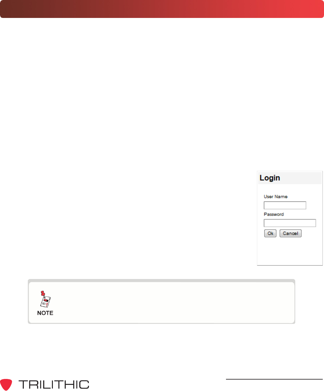
Perform the following steps to login to the EASyCAP Encoder/Decoder:
1. Enter https:// followed by the IP address of the EASyCAP Encoder/
Decoder into the URL bar of the web browser and then press Enter
on your keyboard.
2. The login screen will appear as shown to the right.
3. Enter the username and password for the desired user account and
then select the OK button. The factory default user account has a
username and password of Administrator.
4. The EASyCAP user interface homepage will appear. Select from the
options shown to the left to display the corresponding system
configuration settings.
Each configuration page has an Edit button used to unlock the
user interface. This button will change to a Save button that is
used to save changes before exiting the page.
DRAFT
EASyCAP Encoder/Decoder - Manual
20
Network Settings
Network Interfaces
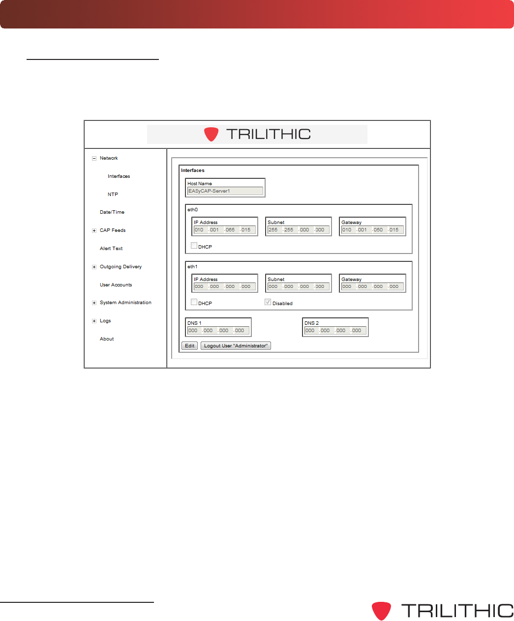
To setup the network interfaces of the Encoder/Decoder, select the plus (+) sign to the left of
Network, and then select the Interfaces link. The Interfaces setup page will be displayed as
shown below.
Network Connection - The EASyCAP Encoder/Decoder must be on a network where CAP
feeds are available and it must also have network connectivity to the EASy Series Encoder/
Decoder. Two different network configurations are possible as follows:
Single Network Connection - If both the EASyCAP Encoder/Decoder and EASy
Series Encoder/Decoder are on the same network (or subnet) only the Ethernet
connection eth0 should be configured. In this configuration select the Disabled check
box for the second Ethernet port eth1, otherwise communications will be unreliable.
Dual Network Connection - If the EASyCAP Encoder/Decoder and EASy Series
Encoder/Decoder are on two different networks (or subnets) both Ethernet connections
eth0 and eth1 must be configured. In this configuration each Ethernet port is assigned
to a different network (or subnet).

DRAFT
EASyCAP Encoder/Decoder - Manual
21
Select the Edit button to change the network settings, and then adjust the following settings:
LAN Port 1 (eth0)
The following settings can be adjusted for LAN Port 1 (eth0)
DHCP - Select this checkbox to enable DHCP to automatically assign the IP
Address, Subnet, and Gateway of the Encoder/Decoder. When this check box is
selected these fields will be grayed out and cannot be manually adjusted.
IP Address - When DHCP is not enabled, enter the IP Address of the Encoder/
Decoder into this field.
Subnet - When DHCP is disabled, enter the Subnet Mask of the Encoder/Decoder
into this field.
Gateway - When DHCP is disabled, enter the Gateway of the Encoder/Decoder
into this field.
LAN Port 2 (eth1)
The following settings can be adjusted for LAN Port 2 (eth1)
Disabled - Select this checkbox to disable this port when only using one Ethernet
connection. When this check box is selected these fields will be set to 0.0.0.0, be
grayed out, and cannot be manually adjusted.
DHCP - Select this checkbox to enable DHCP to automatically assign the IP
Address, Subnet, and Gateway of the Encoder/Decoder. When this check box is
selected these fields will be grayed out and cannot be manually adjusted.
IP Address - When DHCP is not enabled, enter the IP Address of the Encoder/
Decoder into this field.
Subnet - When DHCP is not enabled, enter the Subnet Mask of the Encoder/
Decoder into this field.
Gateway - When DHCP is not enabled, enter the Gateway of the Encoder/Decoder
into this field.
Attempting to assign both network interfaces to DHCP may
cause unreliable communication.
DRAFT
EASyCAP Encoder/Decoder - Manual
22
Select the Edit button and then enter the URL or IP Address of the NTP Encoder/Decoder to
connect to. After making changes, select the Save button to save the NTP Encoder/Decoder
settings.
During initial configuration time and date should be set
manually. Afterwards, if an NTP Encoder/Decoder is configured
the Date/Time will automatically synchronize with the NTP
Encoder/Decoder.
DNS 1 & DNS 2
The following Domain Name Encoder/Decoder (DNS) settings can be adjusted:
DNS 1 - Enter the primary DNS Encoder/Decoder address in this field.
DNS 2 - Enter the secondary DNS Encoder/Decoder address in this field.
After making changes, select the Save button to save the network settings. If the IP Address of
the Encoder/Decoder has changed, you will need to close the browser window and reopen to
login to the Encoder/Decoder at the new IP Address.
Network Time Protocol (NTP) Encoder/Decoder
To setup a Network Time Protocol connection to the Encoder/Decoder, select the plus (+) sign
to the left of Network, and then select the NTP link. The NTP setup page will be displayed as
shown below.
DRAFT
EASyCAP Encoder/Decoder - Manual
23
Date/Time Settings
To adjust the Date/Time settings of the Encoder/Decoder, select the Date/Time link. The Date/
Time setup page will be displayed as shown below.
Select the Edit button to change the Date/Time settings, and then adjust any of the following
settings:
Month - Select the current month from the dropdown list.
Day of Month - Select the current day from the dropdown list.
Year - Select the current year from the dropdown list.
Hour - Select the current hour from the dropdown list.
Minute - Select the current minute from the dropdown list.
Time Zone - Select the time zone from the dropdown list.
After making changes, select the Save button to save the Date/Time settings.
During initial configuration time and date should be set
manually. Afterwards, if an NTP Encoder/Decoder is configured
the Date/Time will automatically synchronize with the NTP
Encoder/Decoder.
DRAFT
EASyCAP Encoder/Decoder - Manual
24
CAP Settings
To setup the CAP feeds to the Encoder/Decoder, select the plus (+) sign to the left of CAP Feeds,
and then select the TCP Feed link. The TCP Feed setup page will be displayed as shown below.
There are two ways to display the CAP Feeds that are currently configured, choose from either of
the following methods:
Select the Previous or Next buttons to scroll through the CAP
Feeds, the settings of the selected CAP Feed will automatically be
displayed.
Select the Choose button to view a list of the CAP Feeds. Select
the name of the CAP Feed and then select the OK button to view
its configuration.

DRAFT
EASyCAP Encoder/Decoder - Manual
25
TCP Feed Settings
Select the Edit button to change the TCP Feed settings, and then adjust any of the following
settings:
Use All Area Blocks - When this box is selected, this allows processing of all the
<area> blocks within a CAP message. If off (unchecked), only the first <area> block will
be processed. This option should be left off (unchecked) in order to comply with current
CAP to EAS implementation guidelines.
Description - Enter the description that you wish to display for this feed in the CAP
Feed List. This description should be detailed enough to be able to easily discern it
within the CAP Feed List.
IP Address - Enter the IP Address of the CAP Feed into this field.
IP Port - Enter the IP communication port number.
After making changes, select the Save button to save the TCP Feed settings.
DRAFT
EASyCAP Encoder/Decoder - Manual
26
Alert Text Settings
To setup the alert text settings for the Encoder/Decoder, select the Alert Text link. The Alert Text
setup page will be displayed as shown below.
The Alert Text setup page is used to configure which additional elements are included in the alert
text. Select the Edit button to change the alert text settings, and then select from the following
check boxes.
Include FCC text - When this box is selected, the EAS Header Translation will be
included in the alert text. This box should always be selected unless the FCC agrees to
drop the requirement for this text to be sent. If the FCC does indeed drop this requirement,
Trilithic recommends that this box should not be selected.
Include <headline> - When this box is selected, the CAP Headline will be included in the
alert text. Trilithic recommends that this box should not be selected.
Include <areaDesc> - When this box is selected, the CAP Area Description will be
included in the alert text. Trilithic recommends that this box should not be selected.
After making changes, select the Save button to save the alert text settings.
DRAFT
EASyCAP Encoder/Decoder - Manual
27
Accepted Events
To setup the accepted events for the Encoder/Decoder, select the Accepted Events link. The
Accepted Events setup page will be displayed as shown below.
The Accepted Events setup page is used to configure which types of events to process. Select
the Edit button to change the accepted events settings, and then select the check box next to each
type of event to process.
After making changes, select the Save button to save the alert text settings.
DRAFT
EASyCAP Encoder/Decoder - Manual
28
Accepted Locations
To setup the accepted locations for the Encoder/Decoder, select the Accepted Locations link.
The Accepted Locations setup page will be displayed as shown below.
The Accepted Locations setup page is used to configure which locations to process. Select the
Edit button to change the accepted locations settings.
Select the Add button to add a location. The Add Location Codes dialog
box will appear, select the state from the dropdown list and then select the
counties from the list. Select the OK button to accept the changes.
Select the location from the list and then select the Subdivisions button to
add a county subdivision. The County Subdivisions dialog box will
appear, select the check box next to the desired subdivisions. Select the
OK button to accept the changes.
After making changes, select the Save button to save the alert text settings.
DRAFT
EASyCAP Encoder/Decoder - Manual
29
Outgoing Delivery Settings
To setup the outgoing delivery settings from the Encoder/Decoder to EASy Series Encoder/
Decoders, select the plus (+) sign to the left of Outgoing Delivery, and then select the Encoder/
Decoder link. The Encoder/Decoder setup page will be displayed as shown below.
There are two ways to display the settings of the encoder/decoders that are currently configured,
choose from either of the following methods:
Select the Previous or Next buttons to scroll through the EAS
encoder/decoders, the settings of the selected EAS encoder/
decoder will automatically be displayed.
Select the Choose button to view a list of the Encoder/Decoders.
Select the name of the Encoder/Decoder and then select the OK
button to view its configuration.

DRAFT
EASyCAP Encoder/Decoder - Manual
30
Encoder/Decoder Settings
Select the Edit button to change the encoder/decoder settings, and then adjust any of the
following settings:
Description - Enter the name that you wish to display for this encoder/decoder. This
name should be descriptive enough to be able to easily discern it within the EAS
Encoder List.
IP Address - Enter the IP address used to connect to the selected encoder/decoder.
Command Port - Enter the TCP command port used to communicate with the
selected encoder/decoder. The default value is 59911.
Audio Port - Enter the TCP port used to transfer audio from the Encoder/Decoder to
the encoder/decoder. The default value is 59919.
Password - Enter the password used to login to the configured Encoder/Decoder. This
should be a special CAP account added to the user accounts of the Encoder/Decoder,
and given EAS Alert and Ethernet permissions in the user account.
Call Sign - Enter the station identification that will be included in the alert text.
No EAN audio - When this box is selected the EAN audio stream will not be used,
Encoder/Decoders will receive EAN audio from a local audio input.
After making changes, select the Save button to save the encoder/decoder settings.
DRAFT
EASyCAP Encoder/Decoder - Manual
31
User Account Settings
To setup the user accounts for the Encoder/Decoder, select the User Accounts link. The User
Accounts setup page will be displayed as shown below.
There are two ways to display the settings of the user accounts that are currently configured,
choose from either of the following methods:
Select the Previous or Next buttons to scroll through the user
accounts, the settings of the selected user account will
automatically be displayed.
Select the Choose button to view a list of the User Accounts.
Select the name of the User Account and then select the OK button
to view its configuration.

DRAFT
EASyCAP Encoder/Decoder - Manual
32
User Settings
Select the Edit button to change the user account settings, and then adjust any of the following
settings:
Description - Enter the description that you wish to display for this user account. This
description should be detailed enough to be able to easily discern it within the User
Account List.
User Name - Enter the user name into this field. This field cannot be changed after
saving the user account. To change the user name in the future, simply delete the
account and create a new account.
Change Password - Select this button to change the user password.
Roles
To set the role of the user select any one of the following checkboxes.
Configurer - This role allows the user to make changes to the configuration of the
EASyCAP Encoder/Decoder.
Upgrader - This role allows the user to upgrade the EASyCAP Encoder/Decoder
software.
User Editor - This role allows the user to make changes to all user accounts. Note
that any user can change their own password and PIN at any time regardless of their
own user account role.
DRAFT
EASyCAP Encoder/Decoder - Manual
33
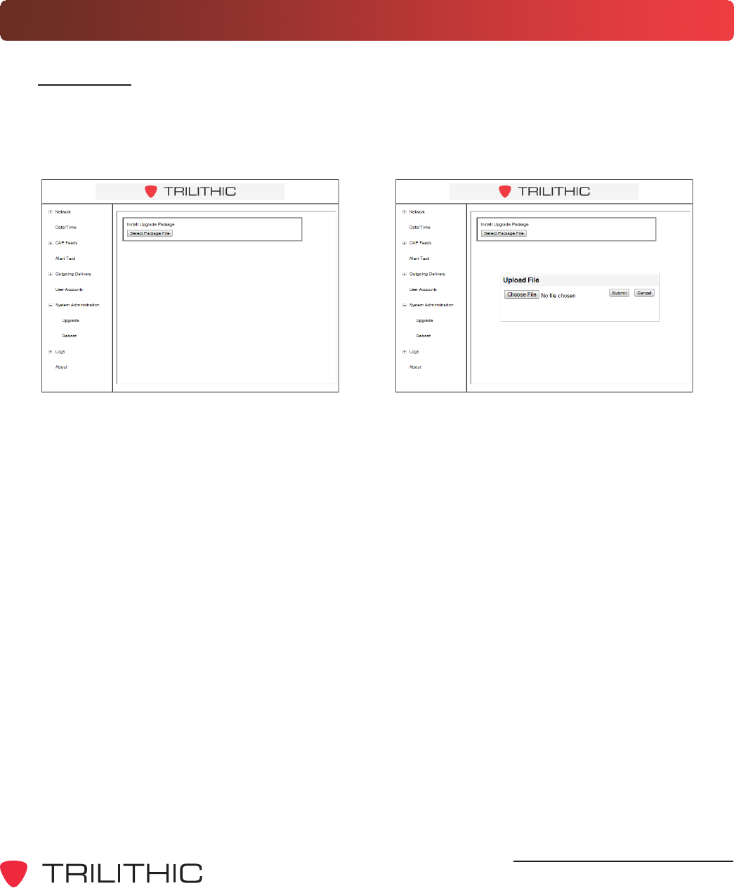
System Administration Settings
Upgrades
To upgrade the EASyCAP Encoder/Decoder software, select the plus (+) sign to the left of
System Administration, and then select the Upgrade link. The Install Upgrade Package
page will be displayed as shown below.
To upgrade the EASyCAP Encoder/Decoder software, select the Select Package File button.
An Upload File dialog box will appear, select the Choose File button to select an upgrade
file.
Once the upgrade file has been choosen, select the Submit button to upgrade the software or
select the Cancel button to exit without upgrading.
DRAFT
EASyCAP Encoder/Decoder - Manual
34
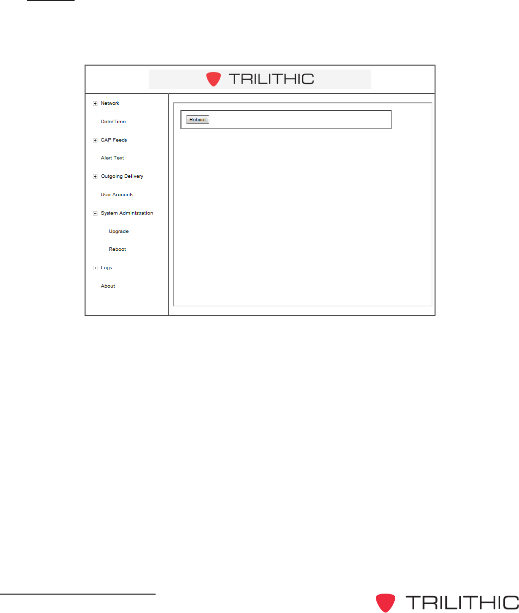
Reboot
To reboot the EASyCAP Encoder/Decoder, select the plus (+) sign to the left of System
Administration, and then select the Reboot link. The Reboot page will be displayed as
shown below.
Select the Reboot button to reboot the Encoder/Decoder.
DRAFT
EASyCAP Encoder/Decoder - Manual
35
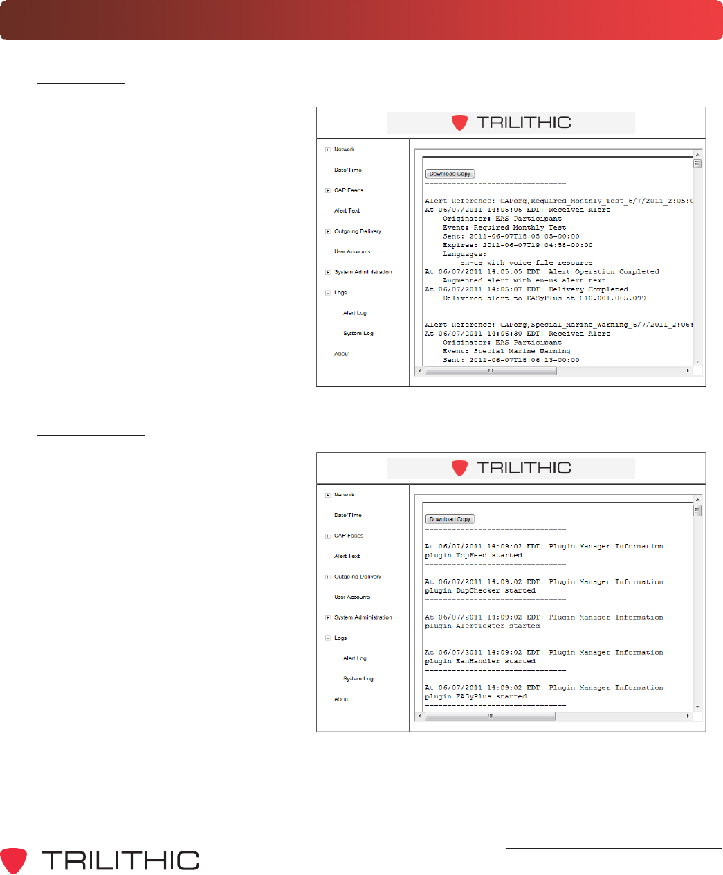
Logs
Alert Log
To view the CAP Alert information,
select the plus (+) sign to the left of
Logs, and then select the Alert Log
link. The Alert Log page will be
displayed as shown below. To
download a copy of the alert log in
ASCII text file format, select the
Download button.
System Log
To view the general system and
application information, select the
plus (+) sign to the left of Logs, and
then select the System Log link.
The System Log page will be
displayed as shown below. To
download a copy of the system log
in ASCII text file format, select the
Download button.
DRAFT
EASyCAP Encoder/Decoder - Manual
36
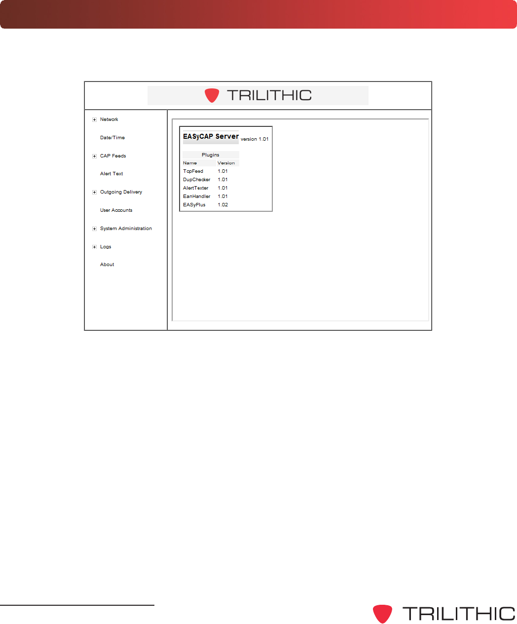
About
To view the EASyCAP version and plugin version information, select the About link. The About
page will be displayed as shown below.

DRAFT
EASyCAP Encoder/Decoder - Manual
37
Chapter 4
4. Appendix
Specifications
General Specifications
E.A.S. Encoder/Decoder compliant with all requirements defined in Part 11 of the FCC rules.
E.A.S. Encoder supports NWS SAME protocol decoding, including 1050 Hz tone detection.
Operating Temperature: 0 to +50 C
Max. Operating Humidity: 95%
Supply Voltage: 117 VAC +/- 15%
Processor and Memory
Dual Core Processor, 2GB RAM, 32GB SSD drive (minimum)
Chassis
2U RU chassis with 3.5 320x240 color touch-screen LCD and speaker on the Front Panel
Communications
(2) RS-232 serial ports available on male DB-9 connectors
(4) USB ports
(2) 10/100/1000 BaseT Ethernet ports available on USB/RJ45 combo jacks
Audio
(6) Balanced 600 Ohm audio inputs for EAS monitoring each input can be configured for
external audio or an optional internal radio receiver.
(1) Line input and (1) line output
(2) Balanced analog audio outputs, 600 Ohm
(1) Balanced stereo analog audio switch, 600 Ohm

DRAFT
EASyCAP Encoder/Decoder - Manual
38
Video
NTSC video character generator
RS-170A color analog video (source only, does not overlay onto video)
24-bit color, True Type fonts, static text, crawl text (up to 400 characters), and images
Analog video switch with video bypass for fail-safe operation synchronized to the input video to
provide a clean switch on the vertical sync
General Purpose Inputs and Outputs
(6) General purpose outputs: isolated relay, maximum rating of 0.3 A @ 120 VAC or 1A @ 30
VDC
(2) TTL outputs: each TTL output can drive 2 TTL loads
(4) General purpose inputs: optically isolated dry contact closure inputs
Radio Receiver Boards
(2) Radio receiver boards can be installed into the EASyCAP
(3) Radio receivers are installed per board, each can be configured as AM, FM, or NOAA
AES-EBU Digital Audio Board
(2) AES-EBU digital audio switches: each switch provides a pair of channels, 100 Ohm XLR
Alert audio automatically locks to the incoming bit rate and sample rate (up to 192 KHz)
Configurable as a switch or an audio source
Communications Board
(1) 10/100 BaseT Ethernet port
(1) RS-485 serial port
(1) Telephone MODEM (33.6K & voice)

DRAFT
EASyCAP Encoder/Decoder - Manual
39
THIS PAGE LEFT INTENTIONALLY BLANK

DRAFT
EASyCAP Encoder/Decoder - Manual
40
Trilithic EAS 2-Year Limited Warranty
Trilithic, Inc. (Trilithic) warrants to the buyer that the product will be free from defects in materials and workmanship,
under normal use, operating conditions and service for a period of two (2) years from date of delivery. Trilithic
reserves the right, before having any obligation under this limited warranty, to inspect the damaged product, and all
costs of shipping the product to Trilithic for inspection shall be borne solely by the buyer. Trilithics obligation under
this limited warranty shall be limited, at Trilithics sole option, to replacing or repairing the product, or to replacing or
repairing any defective part, F.O.B. Indianapolis, Indiana. If neither of the two options is reasonably available, then
Trilithic, in its sole discretion, may provide a prorated refund to the buyer of the purchase price of the product, as
evidenced by the proof of purchase, less any applicable service fees in accordance with the following schedule:
months 0-3 = 100%; months 4-12 = 50%; and months 1324 = 25%. Batteries and fans are not included or covered
by this limited warranty. Any product or part that is repaired or replaced under this limited warranty shall be covered
only for the remainder of the original warranty period which applied to the original product or part, or for ninety (90)
days, whichever is longer. All products or parts that are exchanged for replacement shall become the property of
Trilithic.
In order to recover under this limited warranty, buyer must make a written claim to Trilithic within sixty (60) days of
the occurrence and must present acceptable proof of original ownership of the product (such as an original receipt,
purchase order or similar documentation). In order for this limited warranty to be effective, the product must have
been handled and used as set forth in the documentation accompanying the product and/or its packaging. This
limited warranty shall not apply to any damage due to accident, misuse, abuse, neglect, fire or other casualty.
Further, this limited warranty shall not apply to any product which has been altered or where the damage was
caused by a part not supplied by Trilithic. Trilithic retains the final decision whether a product is within warranty
conditions.
THE REMEDY SET FORTH HEREIN SHALL BE THE ONLY REMEDY AVAILABLE TO THE BUYER AND TO THE
FULLEST EXTENT PERMITTED BY LAW, IN NO EVENT SHALL TRILITHIC BE LIABLE FOR ANY SPECIAL,
INCIDENTAL, PUNITIVE OR CONSEQUENTIAL DAMAGES, INCLUDING BUT NOT LIMITED TO, LOST
REVENUES, LOST PROFITS, LOSS OF USE OF SOFTWARE, LOSS OR RECOVERY OF DATA, DOWNTIME,
REPLACEMENT EQUIPMENT AND ANY THIRD PARTY CLAIMS ARISING OUT OF ANY THEORY OF RECOVERY
INCLUDING WARRANTY, CONTRACT, STATUTORY OR TORT IN CONNECTION WITH THE PRODUCT, EVEN IF
TRILITHIC HAS BEEN ADVISED OF THE POSSIBILITY OF SUCH DAMAGES. NOTWITHSTANDING THE
FOREGOING, IN THE EVENT THAT THIS LIMITED WARRANTY FAILS OF ITS ESSENTIAL PURPOSE, IN NO
EVENT SHALL TRILITHICS ENTIRE LIABILITY TO BUYER EXCEED THE PURCHASE PRICE OF THE
DEFECTIVE PRODUCT.
EXCEPT FOR THE LIMITED WARRANTY PROVIDED HEREIN, TO THE FULLEST EXTENT PERMITTED BY LAW,
TRILITHIC DISCLAIMS ALL WARRANTIES, EXPRESSED OR IMPLIED (INCLUDING WITHOUT LIMITATION, ANY
IMPLIED WARRANTIES OF MERCHANTABILITY OR FITNESS FOR A PARTICULAR PURPOSE), WITH RESPECT
TO THE PRODUCT OR ITS SUITABILITY FOR ANY USE INTENDED FOR IT BY THE BUYER. TO THE EXTENT
ANY IMPLIED WARRANTIES MAY NONETHELESS EXIST BY OPERATION OF LAW, ANY SUCH WARRANTIES
ARE LIMITED TO THE DURATION OF THIS LIMITED WARRANTY.
This limited warranty is non-transferable. This limited warranty does not affect any other legal rights buyer may have
by operation of law. No agent, reseller, distributor or business partner of Trilithic is authorized to modify the terms of
this limited warranty on behalf of Trilithic.
DRAFT

DRAFT
9710 Park Davis Drive
Indianapolis, IN 46235
(317) 895-3600
www.trilithic.com
P/N 00102XXXXX 09/11 Made in U.S.A.