Trilithic EASYPLUS-1 Emergency Alert System User Manual
Trilithic, Inc. Emergency Alert System Users Manual
Operational Manual

EASy-PLUS® User Manual
– 1
TRILITHIC
Rev 1.02
Model EASy-PLUS®
Emergency Alert System
Encoder/Decoder
User’s Manual
P/N 0010224001

EASy-PLUS® User Manual
2 – TRILITHIC
Rev 1.02
Trilithic Incorporated’s latest innovation for your Emergency Alert System is the EASy-PLUS® Encoder/
Decoder. The fully featured E.A.S system, highlighted by the EASy-PLUS® Encoder/Decoder was designed with the
smallest of cable systems in mind, and can handle a system serving 100 subscribers as well as systems handling over
2,000,000 subscribers. With Trilithic’s embedded DSP technology and manufacturing, standard features such as
FLASH BIOS will guarantee that your EASy-PLUS® platform will never go out of style. Periodic updates to the
platform are handled with the ease of a simple download from our WEB site. No more disassembly just to change
proms or software. With Trilithic’s EASy-NET® option, a simple phone call from your desktop PC to any one of
your remote headends, allows you to retrieve the last 100 E.A.S. events from nonvolatile memory for logging and
printing at your office. You’ll never miss your FCC required logging because of printer failures, paper jams or lack
of paper. Innovations such as built-in AM/FM/NOAA selectable tuners, automatically generated and programmable
FCC weekly testing, remote hub-site transmitter, and complete Motorola® digital platform compliance, truly makes
this your Emergency Alert System of choice.
The EASy-PLUS® has the following standard and built-in, features and benefits:
§EASy-PLUS® enables parsing of F.I.P.S. codes
The new Trilithic EASy-PLUS® encoder/decoder distributes individual analog E.A.S. messages structured
for, or earmarked for, one specific community or up to sixteen (16) communities located within multi-trunk
output headends.
§Flash BIOS
Trilithic’s new EASy-PLUS® encoder/decoder eliminates the need to remove the unit from the rack, pull the
cover or lid and change or upgrade chipsets and proms. Government-regulation modifications or changes,
new programming, additional advancements, and many other new features, can easily be handled through a
simple upload via the WEB.
§Programmable RWT (Required Weekly Test) for Automatic Triggering
This feature allows your E.A.S. system to automatically generate a random RWT event, once, within each
seven (7) day window, satisfying the FCC requirement for cable systems generating and logging their own
weekly test.
§Stores the most recent 100 emergency alerts
A nonvolatile Emergency Alert Storage System eliminates the need for attaching a printer at the headends’
encoder/decoder to view the most current alerts or events. A continuous update of the last 100 E.A.S.
events triggered through Trilithic’s EASy-PLUS® encoder/decoder can be downloaded via a PC at the
headend, or through the optional EASy-NET® telephone interface anywhere in the country.
E.A.S. events can easily be archived and/or printed on an external dot-matrix printer at the customer’s
convenience.
Logfile is word-processor compatible.
§Two (2) internal radios that are each tunable as AM, FM, or NOAA radios
This means you will not have to purchase any additional radios to meet the FCC requirement of LP-1 and
LP-2 monitoring stations. Simply tune each of the two radio receivers to either AM or FM, to match the
designated LP-1 and LP-2 stations assigned for your area, or the NOAA frequencies if so needed.
Dual cards can be installed giving four (4) internal radio selections.
§Four (4) external radio inputs for added monitoring capabilities
This feature allows you to meet the requirements dictated by some State Emergency Management Plans that
may require a possible third, fourth or more monitoring selections.
§Remote hub-site insertion transmitter is included as standard equipment
An internal AFSK TX transmitter is included as standard equipment in the new EASy-PLUS® encoder/
decoder. This transmitter eliminates all external remote TX components of earlier E.A.S. systems.

EASy-PLUS® User Manual
– 3
TRILITHIC
Rev 1.02
The AFSK TX transmitter is self-contained, and includes audio switching capabilities for “tune-to” audio
distribution and remote hub-site support via Trilithic’s Virtual Controller.
§Three (3) Programmable dry-contact-closure relays
These programmable relays can be conveniently used for directly driving comb generators, Motorola® OM-
1000(s) for digital E.A.S., and multi-vendors distribution switches.
§Audio D/A outputs
Four (4) outputs are included on the EASy-PLUS® encoder/decoder allowing for simple audio distribution
utilizing all technologies of switching.
§Latest DSP Technology
Trilithic’s use of Digital Signal Processing provides the most current engineering and manufacturing
processes available.
§EASy-Plus Setup Program
The simple, user-friendly setup program walks you through the entire system setup easily, upon initializa-
tion. No guess work involved.
§EASy-Plus Standard Features
The EASy-PLUS® encoder/decoder has a built-in Character Generator, a Microphone for generating your
own messages, front-panel Speaker, TTL control lines, front panel Keypad entry, and an Audio Distribution
Amplifier.
§Trilithic, Inc. is an ISO-9001 Certified company.
§Trilithic, Inc., has a dedicated Marketing, Sales and Engineering in Indiana, New York and North
Carolina committed solely to YOUR current E.A.S. needs and your future E.A.S. support.

EASy-PLUS® User Manual
4 – TRILITHIC
Rev 1.02
CONTENTS
SECTION 1
GENERAL INFORMATION..................................................................................................................................................6
1.1 Introduction
1.2 Specifications
1.3 FCC Certification 7
1.4 Warranty 8
1.5 Claims for Damage in Shipment
1.6 Technical Support
SECTION 2
UNDERSTANDING THE EASy-PLUS® SYSTEM.................................................................................................................9
2.1 Introduction
2.2 Unpacking and Inspection
2.3 Front Panel
2.4 Back Panel 10
2.5 Terminal Connections
SECTION 3
PRE-INSTALLATION SYSTEM CHECK...............................................................................................................................11
3.1 Initial Power Application
3.2 Self-Testing the Encoder/Decoder
3.3 Testing the Parallel Printer Port
3.4 Testing the Digital Voice Recorder
3.5 Testing the Internal Character Generator
SECTION 4
BASIC PROGRAMMING OF THE EASy-PLUS ENCODER/DECODER...............................................................................12
4.1 Introduction
4.2 Accessing Front Panel Setup Menu
4.3 Front Panel Menu Items
SECTION 5
ADVANCED PROGRAMING OF THE EASy-PLUS ENCODER/DECODER..........................................................................13
5.1 Introduction
5.2 Loading Setup Program onto your PC or Laptop
5.3 EASy-PLUS Software Setup Program
System
Counties
Events
Encoder
EAS Logs
Audio In
Audio CFG
CGs
Hubs
I/O CFG
SECTION 6
EASY-PLUS® ENCODER/DECODER INSTALLATION AND WIRING...................................................................................20
6.1 Introduction Single (Composite) I.F. Replacement
6.2 Selecting a “Designated E.A.S. Channel” at I.F.
6.3 LS-16P Lossless Splitter Placement and Connection
6.4 Auxiliary I.F. Switch Installation (SW-4)
6.5 Single (Composite) I.F. Source Modulator Installation (IFS-3)
6.6 Precision I.F. Level Alignment of the LS-16P Lossless Splitter
6.7 Procedure for precision I.F. Alignment
SECTION 7
I.F. (COMPOSITE I.F., AUX. I.F., SINGLE I.F.) INTERFACE AND INSTALLATION...............................................................22
7.1 Introduction Single (Composite) I.F. Replacement
7.2 Selecting a “Designated E.A.S. Channel” at I.F.
7.3 LS-16P Lossless Splitter Placement and Connection
7.4 Auxiliary I.F. Switch Installation (SW-4)
7.5 Single (Composite) I.F. Source Modulator Installation (IFS-3)

EASy-PLUS® User Manual
– 5
TRILITHIC
Rev 1.02
7.6 Precision I.F. Level Alignment of the LS-16P Lossless Splitter
7.7 Procedure for precision I.F. Alignment
SECTION 8
COMB GENERATOR INTERFACE and INSTALLATION.....................................................................................................28
8.1 Introduction
8.2 S
8.3 L
8.4 A
8.5 S
8.6 P
8.7

EASy-PLUS® User Manual
6 – TRILITHIC
Rev 1.02
SECTION 1
GENERAL INFORMATION
1.1 INTRODUCTION
The EASy-PLUS® encoder/decoder is a third generation product from Trilithic, Inc. The encoder/decoder is a fully self-
contained system, which includes a NTSC video character generator output, multiple balanced audio outputs, audio and
video switching, 100 message queue, speaker and microphone, two internal AM/FM/NOAA radios and four program-
mable contact closures used for such things as OM-1000 digital switching.
The EASy-PLUS® E.A.S. Encoder/Decoder is a two-U rack mounted control center capable of performing manual or auto-
mated EAS messaging for cable Headends and Hub sites, in accordance with CFR 47 part 11 FCC regulations, and the
EAS Cable Handbook.
The EASy-PLUS® receives E.A.S. messages from up to six audio sources (internal or external), decodes the message, and
operates Cable System equipment to replay the message for subscribers. In addition, messages can be originated by the
user via local or remote control of the EASy-PLUS®. The E.A.S. audio sources for the EASy-PLUS® include internal AM/
FM/NOAA radios and external audio inputs that can be connected to any known E.A.S. audio source. E.A.S. audio is
decoded by the internal AFSK circuitry, sorted, and then interpreted to determine the type of emergency or test. The
locations codes for which the emergency applies, and other information supplied in the E.A.S. header are also decoded. If
a voice message is contained in the E.A.S. message, it is recorded for playback to subscribers. E.A.S. messages then
pass through a series of tests to determine if the message matches predefined, user configurable filters and parameters for
your location. E.A.S. activation of the cable system then automatically occurs. To play an E.A.S. message to your subscrib-
ers, the EASy-PLUS® activates TTL drivers and Contact Closures, as well as sending commands via RS-485 and High
Data Rate AFSK. The EASy-PLUS® also supplies pertinent video and re-encodes and plays the E.A.S. FSK header and
recorded audio. The TTL drivers, Contact Closures, and RS-485 commands activate your interface equipment (i.e. I.F.
switching, comb generator, baseband character generators) throughout the headend to provide the emergency audio and
video to all channels of the cable system. In addition to the E.A.S. messaging capabilities, the EASy-PLUS® logs all
received and transmitted messages to a printer, the LCD display, and it’s internal log storage area.
The EASy-PLUS® has an optional dial-in telephone interface and a unique remote feature using EASy-NET® optional
software for remote control of the entire system. Using the EASy-NET® software, the operator can generate any event
code and header by simply clicking on the list of events. Prerecorded, or live audio can also be added to the event.
FLASH-BIOS is used to update the EASy-PLUS® nonvolatile memory, programming, and FCC event codes list.
The EASy-PLUS® encoder/decoder has the ability to parse FIPS codes out to individual counties or areas in conjunction
with the appropriate wiring architecture of the cable headend. This keeps the interruptions to a minimum for customers
not affected by the alerted area.
Trilithic’s unique AFSK transmitter card comes standard in the system. The AFSK signal alerts Trilithic’s downstream
Virtual Controllers to perform channel insertions at remote hubs, OTNs, and headends for channels not originating at the
master headend.
The EASy-PLUS® encoder/decoder can handle cross-county applications as well as cross-state-line scenarios. Multiple
states and counties can easily be added with a click-of-the-mouse.
1.2 UNPACKING AND INSPECTION
When your system arrives, immediately inspect its shipping container and contents for visible damage. Keep all packing
materials until equipment performance has been confirmed. If any of the equipment is damaged or fails to operate
properly due to transportation damage, file an immediate claim with the transportation company or, if insured separately,
with the insurance company.
The EASy-PLUS® encoder/decoder may, or may not, arrive in a single shipping container. If it arrives in its own
container, the EASy-PLUS® is a completely self contained system. However, the following is a list of components
associated with the EASy-PLUS® that will ship in the same container:
One (1) 3 1/2” diskette or a CD which contains the Windows based software setup program
One (1) null-modem 9-pin serial data cable
One (1) AC power cord
1.3 SPECIFICATIONS
Front Panel
Protocol FCC EAS codes, baud rate of 520.83 bits per second, 2083.3 Hz and 1562.5 Hz mark and
space frequencies, respectively.

EASy-PLUS® User Manual
– 7
TRILITHIC
Rev 1.02
Attention Signal Dual tone, 853 Hz and 960 Hz. Programmable between 8 and 25 seconds.
Password Protected Menus and tests are enable using a programmable 4 digital front panel code.
Front panel menu Used for localized setup and enabling a Required Weekly Test.
Front panel display Indicates user activity
Message display for active messages
Radio signal input actives.
GENERAL SPECIFICATIONS
E.A.S. Encoder/Decoder compliant with all requirements defined in Part 11 of the FCC rules.
E.A.S. Encoder supports NWS SAME protocol decoding, including 1050 Hz tone detection.
Operating Temperature: 0 to +50 C
Max. Operating Humidity: 95%
Supply Voltage: 117 VAC +/- 15%
MECHANICAL SPECIFICATIONS
Chassis: 2U x 19” x 11” Rackmount Enclosure
Back Panel: Two RS-232C Serial ports available on DB-9 connectors
RS-485 Serial port available on a RJ-12 connector
Parallel port available on a DB-25 connector
I/O and Audio ports are available on modular terminal blocks
Video ports are available on 75 ohm BNC connectors
Antenna inputs are available on 75 ohm “F” connectors
Display: 20 characters by 4 row alphanumeric LCD matrix
LED Back lighted
Super-twist LCD
Controls: 4 x 4 Keypad (16 keys)
Conductive Rubber, Tactile Keys
Numbers 0-9 (and letters A—Z)
X (cancel) key
Checkmark (enter) key
Up, Down, Left, and Right arrows
Serial Interface:
RS-232C compliant interface to standard PC or Laptop PC running Trilithic Setup/control
software (in window’s)
E.A.S. Monitoring: Monitors up to 6 inputs simultaneously, including;
Two Internal Programmable radios (on internal expansion port #1)
Two Receivers per Radio Board each receiver is selectable as AM, FM, or NOAA Band,
frequency, and amplitude of each receiver is configurable from the Front Panel.
75 ohm “F” connectors for the antenna inputs.
Two External Audio inputs (600 Ohm Balanced)
External input 2 can be configured for an external microphone
Two optional radios or audio inputs on internal expansion port #2
Audio inputs: Inputs described in E.A.S. Monitoring Section
Internal Microphone (available on Front Panel)
Telephone Input (optional)
Note: All Inputs have Automatic Gain Control (AGC)
Audio Outputs: All digital audio generation/recording from codes operating at 48 Khz
Four Monaural, Balanced Audio Outputs
Internal Speaker
Telephone Audio Output to the Telephone Access Board (optional)
FSK Audio Switch: Stereo, Balanced Audio Switch to insert FSK onto Audio Channel
Volume Control provided for each Output (Balanced Outputs, Speaker, Telephone, AFSK)
Virtual Controller AFSK Generator
Internal AFSK Encoder for Communicating with Virtual Controllers Internal stereo balanced
audio switch is provided to insert AFSK onto an Audio Channel
CONTROL AND COMMUNICATION INPUTS/OUTPUTS:
Ten TTL Output Ports
Each output can drive a minimum of 2 loads
Two TTL’s Dedicated to E.A.S. Channel, Eight TTL’s are User Programmable
Four Contact Closures
Each relay is capable of switching 2A @ 12 Vdc

EASy-PLUS® User Manual
8 – TRILITHIC
Rev 1.02
All Contact Closures are User Programmable
Two RS-232C Serial Ports (input and output communications)
One RS-485 Serial Port for communications with Trilithic Devices (CG’s, Hubs, etc.)
One Standard Parallel Port for Printing ASCII text (IEE1284 compliant)
INTERNAL CHARACTER GENERATOR:
Includes a stereo audio switch to replace Program audio with the E.A.S. Audio Message
Gen-locks to a video source or creates stand-alone video (RS-170 NTSC)
Capable of providing a Full-Page replacement, static text, and crawls
Initial Release includes a Mini-Messenger, Color CC Option that will be available in the future
MEMORY AND CONTROLLER:
Firmware upgrades are accomplished via a Serial Port (from a Windows PC)
Up to 64 Event Records and 64 FIPS Codes can be programmed
Maintains a Log of the last 100 E.A.S. Alerts or Messages
Two Minutes, nonvolatile audio storage for E.A.S. audio messages
One Minute, nonvolatile audio storage for a Tune-To (prerecorded) message
EXPANSION PORTS: One TTL Expansion port allows up to 48 additional TTL’s or Contact Closures to be added
Additional IO can be configured for Location Routing or Headend Equipment
One Audio Expansion port allows two additional internal radio receivers or two audio ports
One Bus Expansion port provides the ability to add one of the following optional devices:
Telephone Access Board
MODEM Board (with voice - for Telephone Access capability)
COM Expander (additional RS-232, RS-485, or Parallel COM Ports)
Note: Unit comes with two radios on one of two audio expansion ports. These can be removed
to allow an additional expansion port.
1.4 FCC CERTIFICATION The Trilithic EASyPlus (model EASyPLUS-1) is certified to comply
with part 11 of the FCC rules for EAS Encoders and Decoders and is
registered with the FCC under Identification number P4V-EASYPLUS-1.
Changes or modifications to the EASyPLUS not expressly approved by
Trilithic Inc. may void the users authority to operate this equipment.
This equipment has been tested and found to comply with the limits for a Class A digital device,
pursuant to part 15 of the FCC Rules. These limits are designed to provide reasonable
protection against harmful interference when the equipment is operated in a commercial
environment. This equipment generates, uses, and can radiate radio frequency energy and, if
not installed and used in accordance with the instruction manual, may cause harmful interfer-
ence to radio communications. Operation of this equipment in a residential area is likely to
cause harmful interference in which case the user will be required to correct the interference at
his own expense.
1.5 WARRANTY INFORMATION
Following is the Warranty and limitations to Warranty policy of the emergency alert systems equipment
manufactured by Trilithic, Inc.
Trilithic, Inc. warrants the EASy-PLUS® encoder/decoder to meet or exceed all published specifications set
forth in this document and will be free from defects in material and workmanship for a period of two years from
date of shipment of unit. Trilithic, Inc. will repair or replace, at its expense, all parts which are defective from
faulty material or workmanship. This Warranty does not cover equipment which has been misused and/or
altered by the user. Units which become defective during the Warranty period shall be returned to Trilithic, Inc.
with shipping charges prepaid by the USER/BUYER. Replacement or repair shall be the sole remedy of the
SELLER with respect to any nonconforming equipment and/or parts, and shall be in lieu of any other remedy
available by applicable law. All returns to the factory must be authorized by Trilithic, Inc. and in advance of the
shipment. Shipping charges for the EASy-PLUS® unit found to be defective within the first thirty days of the
Warranty period will be paid both ways by Trilithic, inc. NO OTHER WARRANTY IS EXPRESSED OR
IMPLIED. TRILITHIC, INC. IS NOT LIABLE FOR ANY CONSEQUENTIAL DAMAGES THROUGH THE USE
OF THIS EQUIPMENT.
1.6 CLAIMS FOR DAMAGE IN SHIPMENT
Claims for shipping damage should be directed towards the shipping and/or freight delivery service used.
Claims should be made within seven (7) days to insure prompt handling of the claim.

EASy-PLUS® User Manual
– 9
TRILITHIC
Rev 1.02
1.7 TECHNICAL SUPPORT
Technical support is handled first, through the supplier of your equipment. If your supplier does not meet your
service or repair needs, you may contact the manufacturer directly.
Before any Trilithic Emergency Alert System equipment is returned for repair, the supplier, and/or Trilithic will
issue an RMA# (Return Material Authorization). NO EQUIPMENT WILL BE ACCEPTED THAT DOES NOT
HAVE THIS RMA NUMBER PROMINENTLY DISPLAYED ON THE OUTSIDE SHIPPING CARTON AND ON
THE LABEL. A complete and full description, in writing, regarding the service issues with the equipment must
be supplied inside the shipping container with each piece of equipment for which an RMA# has been issued.
The supplier of the EASy-PLUS® system is: The manufacturer and design group is:
TVC Communications Trilithic, Inc.
800 Airport Road 9710 Park Davis Drive
Annville, PA 17003 Indianapolis, IN 46235
Contact: Ron Mountain
Technical Support Manager
Ph (800) 233-7600 extension 134

EASy-PLUS® User Manual
10 – TRILITHIC
Rev 1.02
SECTION 2
UNDERSTANDING THE EASy-PLUS® SYSTEM
2.1 INTRODUCTION
This section includes an overview and description of the EASy-PLUS® equipment including front and rear panel controls,
connectors and displays. The EASy-PLUS® encoder/decoder is the device which, when radio station signals are
supplied to its internal radios, decodes Emergency Alert System header information when monitoring your (local primary)
LP-1 and LP-2 stations, and optionally, your National Weather Service radio signals (on NOAA frequencies 162.400 MHz
(WX2), 162.425 (WX4), 162.450 (WX5), 162.475 (WX3), 162.500 (WX6), 162.525 (WX7), 162.550 (WX1).
Your LP-1 (local primary one) and your LP-2 (local primary two) radios are usually an FM and AM radio station, respec-
tively. These radio stations are assigned in your state emergency plans, usually available on the home WEB site for your
state. Your state plan should detail how your entire state emergency alerting system functions, including your assigned
(SP) state primary frequencies and transmitter locations. Your LP-1 and LP-2 broadcasters typically have the obligation
to pass through to your encoder/decoder the EAN (that’s the Emergency Action Notification-the presidential message)
and the RMT (the Required Monthly Test). You will also receive RWT (Required Weekly Tests), which you may, or may
not, be required to pass on to your cable system headend. You are required to perform your own locally generated RWT,
which can be done from the front keypad, remotely via a telephone, or by using the random RWT generator built into
your EASy-PLUS® system.
Your EASy-PLUS® encoder/decoder is the first piece of equipment to receive the alert from your monitoring stations. It
will decode the signal, format the message into an NTSC video signal (standard analog format) and present this video to
its output port (CG VIDEO OUT). Depending on whether you’ve looped your “designated E.A.S. channel” video through
the CG VIDEO IN, your E.A.S. will either crawl over incoming video, or crawl over an internally generated full-screen
E.A.S. page.
The E.A.S. alert audio associated with the message is also available at the rear connector and is distributed to either
your I.F. switching interface or your comb generator, just as the video output is distributed to these same interfaces.
For remote hub site channel insertions downstream, your EASy-PLUS® has a built-in AFSK in-band data generator for
signally Trilithic’s remote headend/hub site Virtual Controller. The V.C. is used for multiple applications at remote hub
sites for performing channel insertions, remote OM-1000 control for force-tuning Motorola settops during an E.A.S. alert
as well as many other off-site applications.
The FCC requires logging of all incoming E.A.S. events and tests. This is accomplished by applying a customer-
supplied parallel printer (non-Windows driver based) to the DB-25 parallel printer port at the rear of the EASy-PLUS®
system.
Visit WWW.TRILITHIC.COM and click on EAS DIVISION to view or download manuals on all of Trilithic’s E.A.S.
products.
2.2 FRONT PANEL
The EASy-PLUS® front panel contains four items.
Perforated holes for the internal microphone.
Perforated area for the internal speaker.
LCD display
16 button keypad
The keypad is used for rudimentary setup at the cable headend and for initiating the Required Weekly Test. Most setup
features are programmed using the SETUP program provided with each EASy-PLUS® encoder/decoder.
ENCODER
Initiating E.A.S. events (other than the RMT and RWT) is accomplished using the SETUP software. Activation of events
will be covered in the software setup section of this manual.
DECODER
The decoder is an automated mechanism used to decode incoming E.A.S. messages via the baseband radio input
signals to the microprocessor.
2.3 BACK PANEL
RS-232 COM1 Used for uploading setup data from PC or Laptop.
COM2 Future Use.
PARALLEL PORT: Used for connecting a standard (EPSON emulation) parallel printer for FCC mandatory logging of all
incoming E.A.S. events and tests.
CG VIDEO: IN: Connect “designated E.A.S. channel” video, (your tune-to channel), to CG VIDEO IN, if and only

EASy-PLUS® User Manual
– 11
TRILITHIC
Rev 1.02
if, you plan to use a video distribution amplifier at the CG VIDEO OUT to distribute the video back to
your tune-to modulator as well as to your comb generator. NOTE: This is done only if you plan to
use a “tune-to” video and audio message supplied to your comb generator prior to running the alert
on your “designated E.A.S. channel”. This will be explained further in the applications section of this
manual.
OUT: Connect CG VIDEO OUT to the input of your I.F. source modulator or to your comb generator.
If you are using an external video D/A, connect to input of D/A and then connect one output to your
comb generator and one output to your “designated E.A.S. channel” video input.
AUDIO EXPANSION 1:
Ch 1: AM or FM or NOAA radio antenna input.
Ch 2: AM or FM or NOAA radio antenna input.
AUDIO EXPANSION 2:
Ch 3: AM or FM or NOAA radio antenna input.
Ch 4: AM or FM or NOAA radio antenna input.
RS-485: For use with Trilithic external character generators, remote Virtual Controllers.
2.4 TERMINAL CONNECTOR:
TTL OUTPUTS: The individual programmable outputs which switch between TTL levels of 0 and 5 vdc. Each output
is programmable for switching with full system substitution timing, “designated E.A.S. channel”
substitution timing or “designated E.A.S. channel” audio-only switch timing. These outputs are
generally attached to the I.F. switching component (the LS-16P) or the baseband switching compo-
nent (the SW-8). This will be explained in more detail in the headend applications section.
CONTACT CLOSURES:
Used to connect such devices as a comb generator activation and Motorola OM-1000 Red/Black
terminals for digital settop force-tuning.
AUDIO OUTPUTS: E.A.S. alert audio is presented at all four audio outputs. Use these outputs to connect to E.A.S.
distribution equipment such as I.F. source modulator or comb generator.
AUDIO INPUTS: One extra set of baseband audio inputs used as audio input source #5 & #6 for monitoring stations.
AFSK SWITCH: Loop through baseband audio path from a modulator (usually your “designated E.A.S. channel) to
send AFSK tones downstream to the remote hub site Virtual Controllers.
AUDIO SWITCH: Input - Route the “designated E.A.S. channel” audio through for baseband control of “tune-to”
channel. Used usually in conjunction with an external video D/A. See applications section for further
information.
Output - Route the “designated E.A.S. channel” audio through for baseband control of “tune-to”
channel. Used usually in conjunction with an external video D/A. See applications section for further
information.
The INPUT/OUTPUT switch timing correlates to the E.A.S. channel substitution.

EASy-PLUS® User Manual
12 – TRILITHIC
Rev 1.02
SECTION 3
PRE-INSTALLATION SYSTEM CHECK
3.1 INITIAL POWER APPLICATION
When 120 VAC power is applied to encoder/decoder, the system will perform an internal self-check. If the
system suffers from any internal failures, an error message or code will most likely be displayed on the LCD
readout.
3.2 SELF-TESTING THE ENCODER/DECODER
Press the button labeled with a ?
Scroll down to Required Weekly Test (RWT) and initiate.
You should hear the header tones and the Required Weekly Test video should appear at the CG OUTPUT. To
verify, connect VIDEO OUT to a monitory source or to the input of a modulator and view the television screen
for confirmation.
3.3 TESTING THE PARALLEL PRINTER PORT
Attach a standard parallel printer, either dot-matrix, laserjet, or inkjet printer. Make sure the printer does not
require a Microsoft Windows® print-driver. The printer should emulate the standard EPSON® mode for parallel
printers.
THE EASy-PLUS® ENCODER/DECODER CANNOT LOAD A WINDOWS PRINT-DRIVER. USE ONLY AN
EPSON EMULATION (or equivalent) PARALLEL PRINTER.
To test the printer, move through the front panel MENU using the check key and the UP/DOWN ARROWS and
move to the PRINT MEMORY CONTENTS section. Press (Print Function) to see if printer works.
3.4 TESTING THE DIGITAL VOICE RECORDER
Record audio using the front panel microphone.
Playback audio using the menu item for audio playback.
3.5 TESTING THE INTERNAL CHARACTER GENERATOR
Initiate a RWT test and view CG OUTPUT at rear of EASy-PLUS® unit.
3.6 WIRING RECOMMENDATIONS DURING INSTALLATION.
Shielded audio wires for all TTL and audio connections.
Shielded RS-232 and Printer cables.
Shielded (coaxial) video cables.
Shielded RS-485 data cable connected to the EASyPLUS.

EASy-PLUS® User Manual
– 13
TRILITHIC
Rev 1.02
SECTION 4
BASIC PROGRAMMING OF THE EASy-PLUS® ENCODER/DECODER
4.1 INTRODUCTION
You may skip the BASIC PROGRAMMING in Section 4 and proceed directly to Section 5 to program the entire
EASy-PLUS® encoder/decoder’s nonvolatile memory and storage. The following procedure will require a PC or
Laptop computer running Microsoft Windows 95 or later.
The encoder/decoder does not need its setup software to be programmed. The basic functionality of the
system can programmed from the front panel keypad to make the system functional for your headend. Basic
functions include setup items such as radio station channels to monitor, record and playback of “tune-to” audio
track, selecting manual or automatic mode, two-tone duration, time and date, selection of county/FIPS code,
and sending an RWT message and EOM.
4.2 ACCESSING FRONT PANEL SETUP MENU
To access the menuing system, press the button labeled with the (?) check mark and then enter the factory
default passcode of 2179. The letters EASy = 2179 for the passcode.
Using the UP/DOWN ARROWS to navigate you will have access to the following menu items:
4.3 FRONT PANEL MENU ITEMS
SETUP MONITORING
Select which channels are to be monitored (channels 1-6 at the rear panel inputs)
Select which channel is assigned to LP-1, and LP-2 respectively
Select which channel is assigned the NOAA frequency (WX1 - WX7) (Optional)
TONE CALIBRATION
Setup the 853 Hz, 960 Hz dual tone amplitudes and setup the 1560 Hz and 2083 Hz mark and space
amplitudes.
Select frequency, the tone is played on the speaker and audio outputs
AUDIO VOLUMES
Select speaker or master audio output levels
Select to play an attention tone or route a channel to the speaker/audio output
Allow user to change speaker/audio output volume
PLAYBACK AUDIO
Play recorded E.A.S. message or prerecorded (tune-to) audio track
SETUP AUDIO SOURCE
Select speaker or audio output
Select channels one through six, or NONE
SETUP MANUAL OR AUTOMATIC MODE
Messages are automatically forwarded or require a user to manually resend messages.
SETUP ATTENTION TONE DURATION
Duration of tone specified between 8 and 25 seconds.
SETUP TIME AND DATE
Enter HH:MM:SS for Time
Enter MM/DD/YY for Date
Encoder Message
Select to send a RWT, EOM, or allow PC to upload a message to encode
After selection, will send RWT/EOM or will wait for E.A.S. header from serial port
EASy-PLUS® User Manual
14 – TRILITHIC
Rev 1.02
SECTION 5
ADVANCED PROGRAMMING OF THE EASy-PLUS® ENCODER/DECODER
5.1 INTRODUCTION
A null-modem serial cable supplied with the EASy-PLUS unit should be connected between a serial port a the
PC or Laptop and COM1 at the rear of the EASy-PLUS unit. NOTE: Use only the serial cable supplied with
the system.
The advance setup software has been included in the shipping carton with the EASy-PLUS® encoder/decoder.
It will be either a diskette or a CD. The setup software allows you to setup the encoder/decoder for your
headend for functions such as remote hub site management and channel insertions, FIPS code parsing for
segmented I.F. switching or comb generators, when using a local Virtual Controller and SM-16 Trunk Multi-
plexor (optional), standalone character generators, and much more.
5.2 LOADING SETUP PROGRAM ONTO YOUR PC OR LAPTOP
Load the EASy-PLUS® SETUP program diskette onto your PC or Laptop, using the standard Window’s-based
loading procedure for software, and then run SETUP.EXE for the EASy-PLUS® system.
5.3 EASy-PLUS® SOFTWARE SETUP PROGRAM
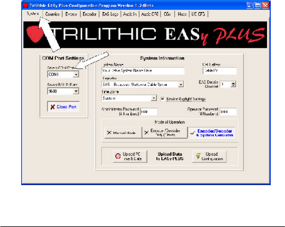
SYSTEM tab
Double-click on your EASy-PLUS® desktop ICON or start EASy-PLUS® using the START/PROGRAMS button
from Windows. The program will open with the SYSTEM tab pre-selected
From the SYSTEM tab, select the appropriate COM port you are using to connect with the EASy-PLUS
system. The default is COM1 and this is normally the port you will be need.
Select 9600 BAUD rate (factory default).
The following listed steps are the only ones needed to bring the EASy-PLUS encoder/decoder on-line and with
its proper identity for you headend:
1. Select all pertinent information on SYSTEM tab.
2. Select STATE/COUNTIES/ADD DELETE on COUNTIES tab.
3. Select the EVENTS you would like to pass-through to the cable system on the EVENTS tab.
4. Go back to SYSTEM tab and select UPLOAD CONFIGURATION.
EASy-PLUS® User Manual
– 15
TRILITHIC
Rev 1.02
ENTERING SYSTEM INFORMATION
From the SYSTEM tab, make the appropriate selections for the following:
SYSTEM NAME
Enter your cable system name.
CALL LETTERS
Enter up to an eight character abbreviation for your cable system name in the CALL LETTERS box.
ORIGINATOR
Select EAS Broadcast Station or Cable System
TIME ZONE
Select the time zone which your headend resides in.
ENABLE DAYLIGHT SAVINGS
Select if your system headend is in a county/parish which adheres to Daylight Savings Time in April.
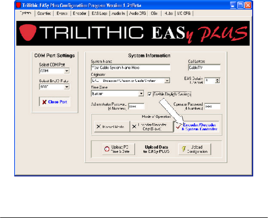
MANUAL MODE/SLAVE MODE/SYSTEM CONTROLLER MODE
Select Encoder/Decoder and System Controller button by left-clicking on it.
Slave mode enables the EASy-PLUS® system to be a slave tied directly to Trilithic’s PSC-901A or PSC-902
rackmount computer. Currently, the only way to interface with Scientific-Atlanta’s DNCS server to run digital
EAS on Explorer or Voyager settops is through the use of the PSC-902 networkable controller.
UPLOAD PC TIME AND DATE (to EASy-PLUS memory)
To set time and date on the EASy-PLUS® system, check for correct DATE, TIME, and TIMEZONE on PC, then
click on the Upload PC Time And Date button.
UPLOAD CONFIGURATION (to EASy-PLUS memory)
After all data selections are made and all fields are filled in using the EASy-PLUS® setup software, come back
to the SYSTEM tab press left-click on the Upload Configuration button.
EASy-PLUS® User Manual
16 – TRILITHIC
Rev 1.02
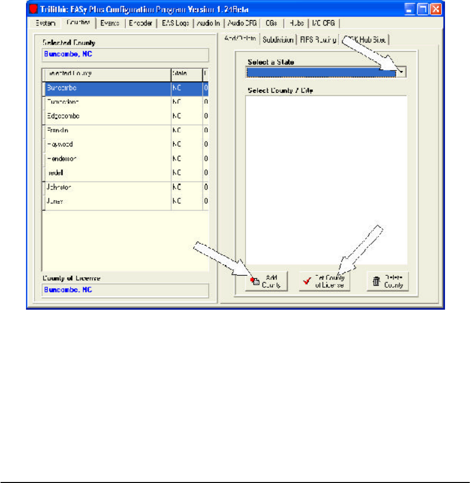
SELECTING COUNTIES
COUNTIES tab
Select the state your headend is in by pulling down the Select a State menu and then left-clicking on the
appropriate states. You may select more than one state.
Scrolling down the list of counties, first select your county that the E.A.S. headend system is located.
Click on the County of Licence button.
Then select the rest of the counties with which you feed cable or fiber to or which you have subscribers
currently residing.
You may select outlying counties which you do not have subscribers in so that TORNADO WARNINGS will
alert your subscriber base ahead of time on severe weather activities in adjacent counties.
EASy-PLUS® User Manual
– 17
TRILITHIC
Rev 1.02
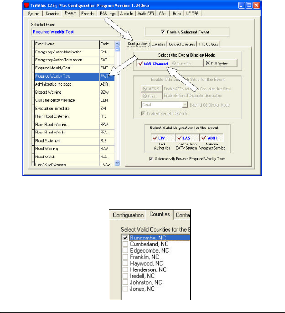
SELECTING EVENTS
EVENTS tab
On the EVENTS tab you will check each event desired, and then Enable Selected Event.
To configure for each, click on the Configuration tab. Select EAS Channel, Tune To, or Full Screen for the
display type of each event.
If remote hub site channel insertions take place, enable the AFSK option by clicking on its button.
Select Valid Originators for the Event enables which type of incoming radio transmission is valid for each
event.
EVENTS Counties
For each event enabled you must attach the COUNTIES to that event. Click on the Counties tab and check
each appropriate county for that event.
EASy-PLUS® User Manual
18 – TRILITHIC
Rev 1.02
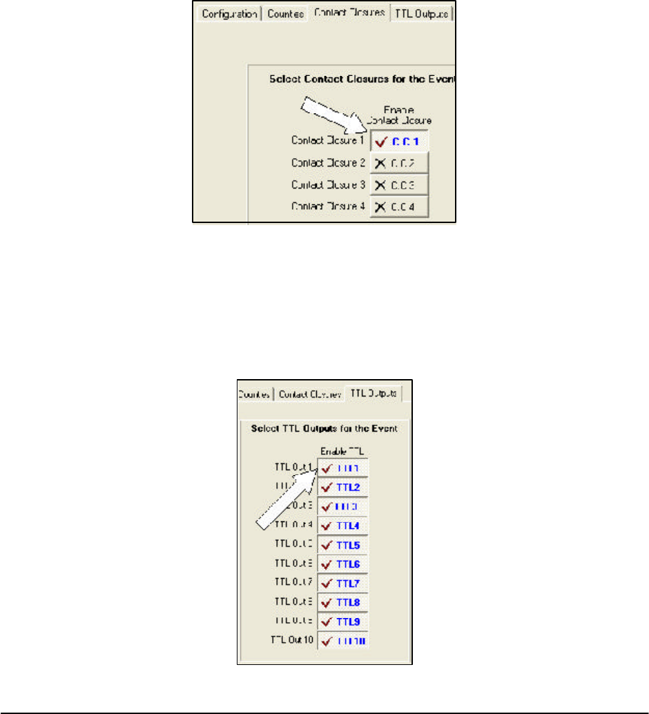
SELECTING CONTACT-CLOSURES
EVENTS Contact Closures
Typical headend components which need a contact-closure to operate are a comb generator or Motorola’s OM-
1000 data modulator.
During the enabling and configuration of each event, there will normally be a contact-closure paired with the
event. The relay contacts are found at the rear of the EASy-PLUS® system.
Enable the necessary number of contact-closures at the rear terminal strip of the EASy-PLUS® unit by clicking
on the Enable buttons. There are four (4) available.
SELECTING TTL OUTPUTS
EVENTS TTL Outputs
Make sure to enable each of the TTL Outputs you intend to use for each event selected. The timing for each
individual TTL output will be set using the I/O CFG tab.
Enabling TOO many outputs is not a problem. Just make sure the outputs you ARE using are enabled.
EASy-PLUS® User Manual
– 19
TRILITHIC
Rev 1.02
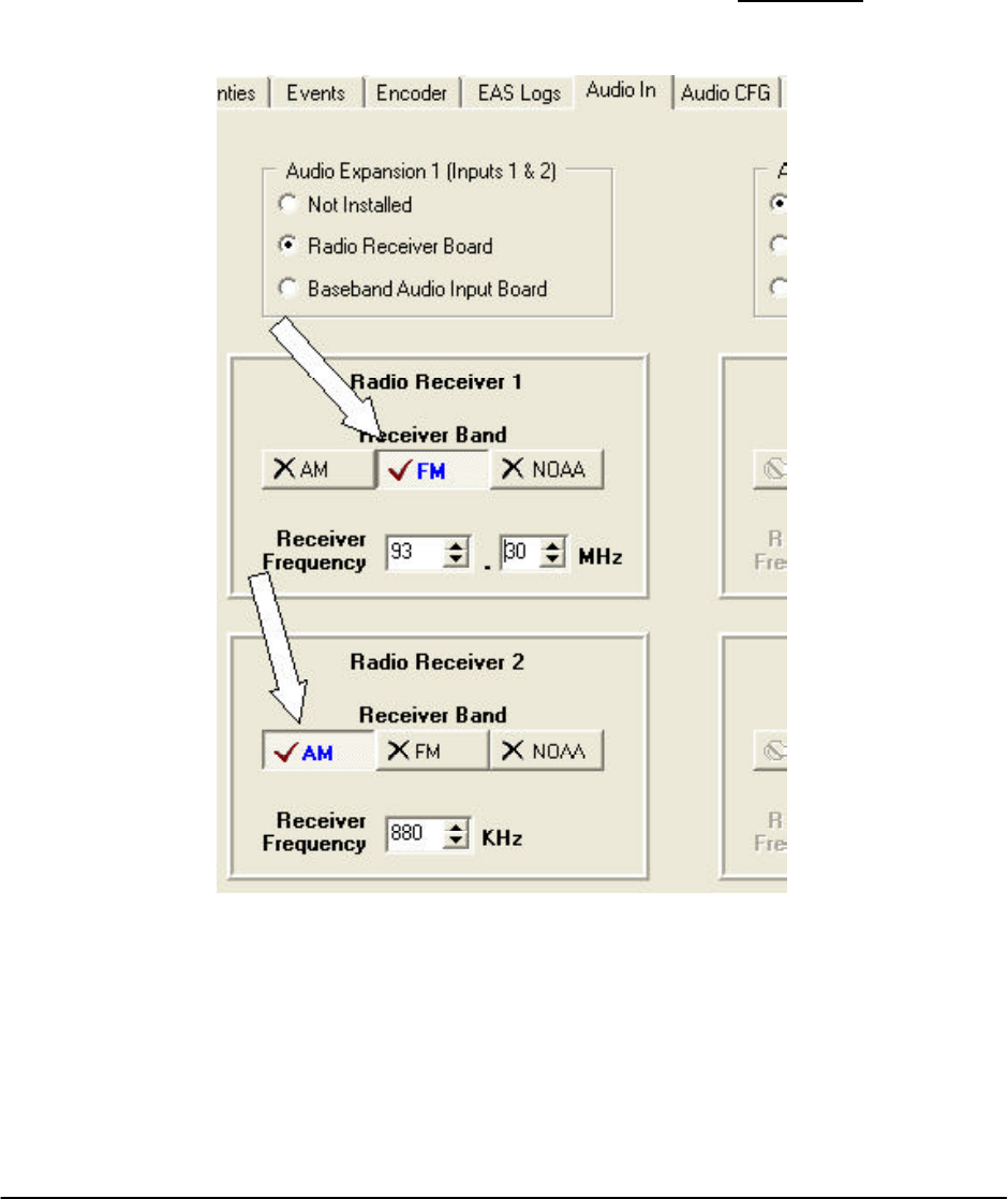
SETTING AUDIO INPUTS
AUDIO CFG
Enable the Radio Receiver Board and then select FM or AM frequency band.
Set the frequencies needed in your local area. Your local LP-1 and LP-2 monitoring stations can be found in
your state’s SECC E.A.S. plan or contact a local radio or television broadcaster.
If you cannot find a copy of the plan try contacting the FCC or go on-line to WWW.FCC.ORG and search their
E.A.S. database.
When selections are complete, go back to the System tab and click on Upload Configuration.

EASy-PLUS® User Manual
20 – TRILITHIC
Rev 1.02

EASy-PLUS® User Manual
– 21
TRILITHIC
Rev 1.02
SECTION 6
EASy-PLUS® Encoder/Decoder Installation and Wiring
6.1 INTRODUCTION
The EASy-PLUS® receives E.A.S. messages from up to six audio sources (internal or external), decodes the message, and
operates Cable System equipment to replay the message for subscribers. In addition, messages can be originated by the
user via local or remote control of the EASy-PLUS®. The E.A.S. audio sources for the EASy-PLUS® include internal AM/FM/
NOAA radios and external audio inputs that can be connected to any known E.A.S. audio source. E.A.S. audio is decoded
by the internal AFSK circuitry, sorted, and then interpreted to determine the type of emergency or test. The locations codes
for which the emergency applies, and other information supplied in the E.A.S. header are also decoded. If a voice message
is contained in the E.A.S. message, it is recorded for playback to subscribers. E.A.S. messages then pass through a series
of tests to determine if the message matches predefined, user configurable filters and parameters for your location. E.A.S.
activation of the cable system then automatically occurs. To play an E.A.S. message to your subscribers, the EASy-PLUS®
activates TTL drivers and Contact Closures, as well as sending commands via RS-485 and High Data Rate AFSK. The
EASy-PLUS® also supplies pertinent video and re-encodes and plays the E.A.S. FSK header and recorded audio. The TTL
drivers, Contact Closures, and RS-485 commands activate your interface equipment (i.e. I.F. switching, comb generator,
baseband character generators) throughout the headend to provide the emergency audio and video to all channels of the
cable system. In addition to the E.A.S. messaging capabilities, the EASy-PLUS® logs all received and transmitted mes-
sages to a printer, the LCD display, and it’s internal log storage area.
7.2 INSTALLATION AND WIRING OF THE EASY-PLUS® ENCODER/DECODER
Typical installation of the encoder/decoder requires the operator to attach radio antenna inputs at the Audio Expansion 1
coaxial input connectors, attach AUDIO and CG VIDEO Outputs to either an I.F. source modulator or audio input to a comb
generator, and attach either TTL control line output to I.F. switching devices or a contact-closure output to the comb genera-
tor. Optional control of the Motorola OM-1000 QPSK modulator is accomplished by using a secondary contact-closure
attached to the red and black terminals at the rear of the OM-1000.
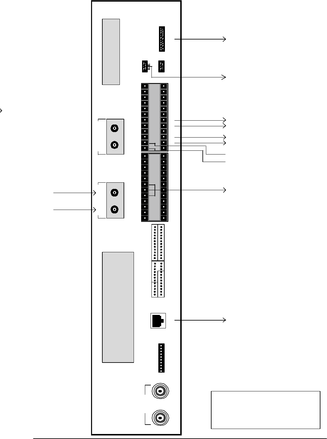
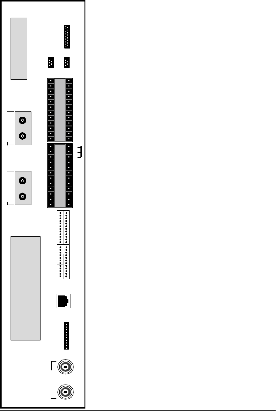
7.3 PINOUT DESIGNATIONS AT THE REAR PANEL OF THE EAS-yPLUS® ENCODER/DECODER.
asf
EASy-PLUS® User Manual
22 – TRILITHIC
Rev 1.02
Parallel Port
TRILITHIC EASy PLUS
FCC ID P4V-EASY-PLUS-1
MODEM - TELEPHONE EXPANSIONAudio Expansion 1
Audio 1 Audio 2
Audio Expansion 2
Audio 3 Audio 4
CG VIDEO
IN OUT
TTL EXPANSION
Com 1
Com 2
RS-232
I1+ I1- I2+ I2- G 01+ 01- 02+ 02- 03+ 03- G
+RI -RI +LI -LI G +RO -RO +L0 -L0 G 04+ 04-
G 1 2 3 4 5 6 7 8 9 10 G
G C
1
NO
1
NC
1
C
2
NO
2
NC
2
C
3
NO
3
C
4
NO
4
G
AUDIO
INPUTS TTL OUTPUTS
AFSK SWITCH
AUDIO
OUTPUTS
CONTACT CLOSURES
AUDIO SWITCH
INPUT / OUTPUT
- + G - + - + G - +
RS-485
DATA
AM or FM Antenna Leads
RS-485 Data Cable for Messenger
II CG interface (optional)
Balanced Audio Output for Comb
Generator or I.F. Source Modulator
Contact-Closure Wires to Connect to
Comb Generator
Contact-Closure Wires to Connect to
Red & Black Terminals of OM-1000
Standard Parallel Printer Cable.
Null-Modem Serial Cable to Connect to PC/
Laptop during software setup (supplied)
TRILITHIC EASy-PLUS®
Encoder/Decoder for
Emergency Alert Systems
REAR PANEL EASy-PLUS®
EASy-PLUS® User Manual
– 23
TRILITHIC
Rev 1.02
SECTION 7
I.F. (Composite I.F., Aux. I.F., Single I.F.) INTERFACE and INSTALLATION
7.1 INTRODUCTION Single I.F. Replacement
Composite I.F. (both visual and aural intermediate carriers on the same coaxial cable) replacement is a technique which
is used to change the program content on a channel without altering the RF output carrier frequency or amplitude. With
this technique you will need to install an I.F. switch in the composite I.F. loop-through on the rear of the modulator or
processor housing (i.e. the channel’s rack mount assembly). Generally, modulators have this I.F. loop on the back of the
housing. In some cases, you may be able to install the loop into the housing to implement this type of switching. For the
E.A.S. application, the alternate I.F. signal will be taken from an independent distribution system which will be explained
as you move through this manual.
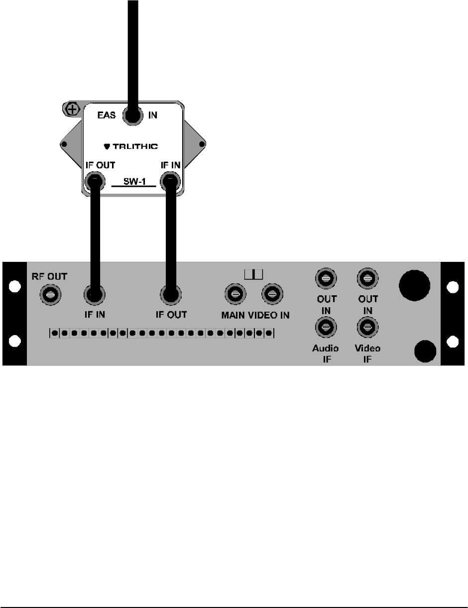
Single (Composite) I.F. Switch Installation (SW-1)
The first step when assembling the E.A.S. system is to install an SW-1 or SW-4 switch on the rear of each modulator or
processor. The SW-1 is a three terminal device used to substitute the current I.F. source with an alternative I.F. source.
The SW-4 switch is a two terminal device with a terminal strip localize as a contact-closure for such chassis as the S-A
Continuum modulators and processors.
For each SW-1 installed, you will need two (2) 75 Ohm cables of equal length about three (3) to six (6) inches in length.
The next step will cause a brief interruption of the channel involved while the I.F switch is being connected, but the signal
will return once the switch is installed.
Connect the 75 Ohm cable from the I.F. OUT of the modulator or processor to the I.F. IN of the SW-1 switch. Connect
the I.F. OUT of the SW-1 switch to the I.F. IN of the same modulator or processor. See the following diagram. You will
I.F. signal fed from the LS-16P
Lossless Splitter
Normal I.F. IN fed from the I.F. OUT
of the modulator or processor
Normal I.F. OUT fed to the I.F. IN
of the modulator or processor
EAS IN
SW-1
I.F. OUT I.F.
TRILITHIC
EASy-PLUS® User Manual
24 – TRILITHIC
Rev 1.02
connect the EAS IN at the SW-1 switch later in this procedure.
Repeat this procedure on all modulators and processors that have a composite I.F. loop-through on the rear of their
housing.
7.2 Selecting a “Designated E.A.S. Channel” at I.F.
You will assign one channel on the cable system as the “Designated E.A.S. Channel”. This is the channel on which all
E.A.S. alerts and messages received via your Local Primary monitoring stations (i.e.: AM, FM, or NOAA) will be
displayed. Depending on installation techniques used, these messages and alerts will appear in the form of a gen-locked
crawl message over either the existing video or over a full page blue background. Selecting a low priority channel (one
which is not trapped or scrambled as it enters every home on the system) as the “Designated E.A.S. Channel” is
optimum. Generally, a community access channel, government channel, or character generator channel in the VHF
television band (i.e.: ch. 2-13) is ideal to use for the “Designated E.A.S. Channel”.
NOTE: IN ALMOST ALL INSTANCES A MODULATOR WITH A COMPOSITE I.F. LOOP WILL BE USED FOR THE
“DESIGNATED EAS CHANNEL”. THERE ARE EXCEPTIONS, SUCH AS BASEBAND OR CHARACTER
GENERATOR EAS SYSTEMS OR COMBINATIONS OF BASEBAND AND I.F. SYSTEMS. THESE EXCEP-
TIONS WILL BECOME APPARENT IN EACH INTERFACE SECTION OF THIS MANUAL.
7.3 LS-16P Lossless Splitter Placement and Connection
The LS-16P is a precision I.F. distribution amplifier (D/A) which has a 20dB continuously variable precision attenuator for
I.F. alignment on each of its 16 output connections. The LS-16P is also used to insert a DC drive voltage on the output
drop cable’s center conductor for activating each SW-1 or SW-4 switch, as well as other LS-16P input connections when
the EAS system is activated.
For most applications, multiple LS-16P(s) will be needed. In all installations, the first LS-16P, which receives its input
EASy-PLUS® User Manual
– 25
TRILITHIC
Rev 1.02
from the I.F. source modulator, should be labeled by the customer as the “Primary LS-16P”.
Any other Primary LS-16P output port may be used to drive Secondary LS-16P(s) input ports or SW-1 and SW-4
switches.
For example, in a typical headend of 46 channels you will need three (3) LS-16P(s). One LS-16P will serve as the
Primary and the two (2) remaining LS-16P(s) will serve as Secondaries. Total channel capacity will be twelve (14) ports
from the Primary LS-16P, with the remaining two (2) ports of the Primary feeding two (2) Secondary LS-16P(s). Two (2)
times sixteen (16), or thirty (32) ports from the Secondary LS-16P(s) added to the fourteen (14) ports leftover from the
Primary LS-16P totals 46 ports.
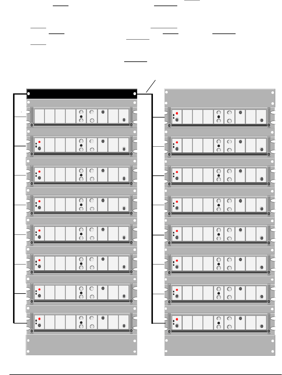
As shown in the following diagram, one (1) LS-16P will serve up to sixteen (16) remotely located SW-1 and/or SW-4
equipped modulators and processors and/or Secondary LS-16P(s). When installing the LS-16P, place in bays or racks
where their distribution coverage will be maximized. See the following diagrams.
Typical LS-16P Placement and Connection.
Bundled drop cable feeding I.F. switches
LS -16P
EASy-PLUS® User Manual
26 – TRILITHIC
Rev 1.02
The composite I.F. distribution system is now installed.
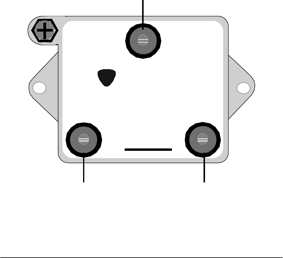
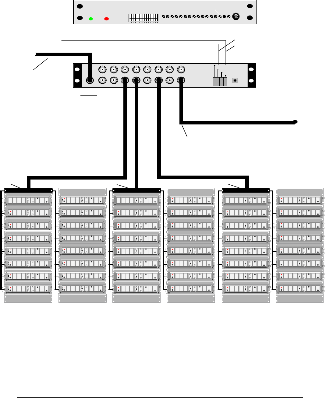
7.4 Auxiliary I.F. Switch Installation (SW-4)
The SW-4 switch is used to locally activate a contact closure on the rear of a modulator or processor enabling the
internal I.F. switch built into the chassis. The E.A.S. I.F. signal and DC current are fed to the input port of the SW-4
switch from the LS-16P. The signal passes through the switch to the Aux. I.F. Input port on the rear of the modulator or
processor. The DC current is blocked at the input to the SW-4 and converted to a normally open (N/O and N/C) contact
closure. The N/O terminal of the SW-4 should be attached to the rear of the modulator on the appropriate screw terminal
to cause the internal I.F. switch to activate when the LS-16P distribution system sends its signal to the SW-4. The ground
terminal on the SW-4 should also be attached to an appropriate grounding point on the modulator or processor.
Rear View
Front View
LS-16P
15 13 11 9 7 5 3 1
I.F. IN
OFF
ON
TEST
LS-16P
??TRILITHIC
16 14 12 10 8 6 4 2Input from I.F.
source modulator
I.F. output to any other LS-16P Lossless Splitter
or any other Aux. I.F. Input or any other SW-1 or
SW-4 switch located at a modulator or processor.
LS-16P
PS
LS-16P LS-16P
Primary LS-16P
E.A.S.
MAST IN
MAST OUT
GND
MAST IN
GND
TTL Control Line from Encoder/
Decoder pins G and 1. Use
headend audio wire.

EASy-PLUS® User Manual
– 27
TRILITHIC
Rev 1.02
7.5 Single (Composite) I.F. Source Modulator Installation (IFS-3)
The I.F. modulator receives its video signal from the CG VIDEO OUT at the rear of the EASy-PLUS® and audio from the
terminal strip and modulates these signals onto I.F. subcarriers. Once the IFS-3 source modulator is mounted, connect
the RF OUT port to the I.F. IN port on the Primary LS-16P.
7.6 Precision I.F. Level Alignment of the LS-16P Lossless Splitter
The LS-16P was designed for precision I.F. output level adjustment. In most instances, different modulators or proces-
sors require different I.F. input levels to maintain proper RF output levels due to the absence of an AGC at the I.F. stage.
It is imperative that the headend maintain the same R.F. output level on each channel during an entire E.A.S. sequence
of events. When alternate I.F. levels match those I.F. levels which are currently present at the rear of the modulator or
processor, system wide stability of the trunk amps, pilot carriers, slopes, R.F. levels and scrambling systems will be
maintained.
DC power is delivered through the coaxial cable’s center conductor to enable the Secondary LS-16P(s), the SW-1(s),
and the SW-4(s) switches.
CAUTION: DO NOT INSTALL FIXED OR VARIABLE ATTENUATOR PADS IN THE INPUT OR OUTPUT CABLES OF
ANY LS-16P LOSSLESS SPLITTER. ELECTRICAL SHORTING OF THESE DEVICES MAY OCCUR.
The I.F. alignment procedure consists of setting the output level of the I.F. source modulator and then setting the output
levels on the Primary and Secondary LS-16P(s) for proper I.F. levels at the rear of the modulators and processors. The
Master Gain on all LS-16P(s) is factory set to unity gain. This adjustment should not need to be reset. Each 20dB
potentiometer on the front panel of the LS-16P is factory set to 0 dB loss (i.e.: 42 dBmV output on each port of the LS-
16P if the IFS-3 is set to 42 dBmV output.)
The test point on the front panel of the LS-16P(s) is to check for signal presence ONLY. No test alignment measure-
ments should be made at this test point.
7.7 Procedure for precision I.F. Alignment:
1. Set the output level of the I.F. source modulator to maximum and then pad its output down to 2 dBmV higher
than the highest I.F. level on your modulators/processors (typically 32-42 dBmV). Set the audio carrier level
13-17 dBmV down from the video carrier.
2. Turn all J1 - J16 dip switches on the front panel of the Primary LS-16P to OFF (disabled), except for those dip
switches which control the feeds of the Secondary LS-16P(s) INPUTS. These dip switches will remain ON
(enabled) at all times.
3. Enable the I.F. alignment mode in the menu system of the EASy-PLUS® encoder/decoder.
4. Using a spectrum analyzer or field strength meter connected to the trunk line test point, identify the channel
under alignment.
5. If applicable, be sure to disable any I.F. AGC switches on all modulators in the headend under I.F. alignment.
6. Looking at the channel under alignment on the spectrum analyzer or field strength meter, note the output level.
7. Turn the dip switch ON (enable) for the channel under setup, ONLY. This will enable the SW-1 or SW-4 switch
at the rear of the modulator or processor under setup. You should now see the “I.F. Alignment Screen” appear
on the television on the channel under test channel.
8. Using the respective potentiometer J1 - J16 on the front of the LS-16P for the channel under alignment, turn
the potentiometer counterclockwise until the exact R.F. output level is achieved on the spectrum analyzer or
field strength meter.
9. Turn the appropriate dip switch back OFF (disable) on the LS-16P.
10. Proceed to the next channel and repeat steps 4 through 10 until all channels are aligned.
11. Turn the I.F. AGC(s) ON for all modulators.
12. At the keypad of the EASy-PLUS unit, take the menu system out of I.F. alignment.
13. Turn all dip switches ON (enable).
CAUTION: The EAS system will not trigger in the automatic mode for an EAS alert while the system is in the “I.F.
Alignment” mode.
You have now completed the composite precision I.F. alignment procedure.

EASy-PLUS® User Manual
28 – TRILITHIC
Rev 1.02
SECTION 8
COMB GENERATOR INTERFACE and INSTALLATION
EASy-PLUS® User Manual
– 29
TRILITHIC
Rev 1.02
Parallel Port
TRILITHIC EASy PLUS
FCC ID P4V-EASYPLUS-1
MODEM - TELEPHONE EXPANSION
Audio Expansion 1
Audio 1 Audio 2
Audio Expansion 2
Audio 3 Audio 4
CG VIDEO
IN OUT
TTL EXPANSION
Com 1
Com 2
RS-232
I1+ I1- I2+ I2- G 01+ 01- 02+ 02- 03+ 03- G
+RI -RI +LI -LI G +RO -RO +L0 -L0 G 04+ 04-
G 1 2 3 4 5 6 7 8 9 10 G
G C
1
NO
1
NC
1
C
2
NO
2
NC
2
C
3
NO
3
C
4
NO
4
G
AUDIO
INPUTS TTL OUTPUTS
AFSK SWITCH
AUDIO
OUTPUTS
CONTACT CLOSURES
AUDIO SWITCH
INPUT / OUTPUT
- + G - + - + G - +
RS-485
DATA
Rear Panel
The Best Thing on Cable
9710 Park Davis Drive
Indianapolis, IN 46235
(317) 895-3600
P/N 0010224001 Made in U.S.A.
TRILITHIC
?

EASy-PLUS® SYSTEMS
INSTALLATION AND OPERATION MANUAL
Emergency Alert System
Model: EASy-PLUS® Encoder/Decoder
Revision: 1.02
The Best Thing on Cable
?TRILITHIC