Trilithic MCAIII Seeker MCA III Cable Installer Meter with Wi-Fi User Manual 360 DSP Operation Manual
Trilithic, Inc. Seeker MCA III Cable Installer Meter with Wi-Fi 360 DSP Operation Manual
Users Manual

Copyright © 2013 Trilithic, Inc. All Rights Reserved. Specications are subject to change without notice. Please contact your sales representative for further information.
Seeker & Seeker MCA III
Leakage Detection System
Operation Manual
This equipment has been tested and found to comply with the limits for a Class B digital device, pursuant to Part 15 of the FCC Rules.
See Page 2 for complete details.
This equipment has been tested and found to comply with Industry Canada Standards. See Page 3 for complete
details.

2
Seeker & Seeker MCA III Operation Manual
FCC Part 15 Compliance
Note: This equipment has been tested and found to comply with the limits for
a Class B digital device, pursuant to Part 15 of the FCC Rules. These limits
are designed to provide reasonable protection against harmful interference
in a residential installation. This equipment generates, uses, and can radiate
radio frequency energy and, if not installed and used in accordance with
the instructions, may cause harmful interference to radio communications.
However, there is no guarantee that interference will not occur in a particular
installation.
Pursuant to FCC 15.21 of the FCC rules, changes not expressly approved by Trilithic, Inc.
might cause harmful interference and void the FCC authorization to operate this product.
The antennas used for this transmitter must be installed to provide a separation distance of at
least 20 cm from all persons and must not be co-located or operating in conjunction with any
other antenna or transmitter.
If this equipment does cause harmful interference to radio or television reception, which can
be determined by turning the equipment off and on, the user is encouraged to try to correct the
interference by one or more of the following measures:
• Reorient or relocate the receiving antenna
• Increase the separation between the device and receiver
• Connect the device into an output on a circuit different from that to which the receiver is
connected
• Consult the dealer or an experienced radio/TV technician for help
The Seeker MCA III can only be used with the following Trilithic approved Wi-Fi antennas:
• P/N 2071677001 - 2.4 GHz antenna
• P/N 2071677004 - 2.4 & 5 Ghz antenna

3
Seeker & Seeker MCA III Operation Manual
Industry Canada Compliance
This device complies with Industry Canada license-exempt RSS
standard(s). Operation of this device is subject to the following two
conditions; 1) This device may not cause harmful interference and
2) this device must accept any interference received, including
interference that may cause undesired operation.
This Class B digital apparatus complies with Canadian ICES-003.
The Seeker MCA III can only be used with the following Trilithic approved Wi-Fi antennas:
• P/N 2071677001 - 2.4 GHz antenna
• P/N 2071677004 - 2.4 & 5 Ghz antenna
Industrie Canada Conformité
Cet appareil est conforme au Cahier des charges sur les normes
radioélectriques d’Industrie Canada concernant les appareils radio
exempts de licence. Le fonctionnement de cet appareil est soumis
aux deux conditions suivantes : 1) cet appareil ne doit pas produire
de brouillage et 2) cet appareil doit accepter tout brouillage, y compris
celui pouvant causer un mauvais fonctionnement de l’appareil.
Cet appareil numérique de classe B est conforme à la norme
canadienne ICES-003.
Le Seeker MCA III ne peut être utilisé avec le Trilithic approuvé antennes Wi-Fi qui suit:
• P/N 2071677001 - 2.4 GHz antenne
• P/N 2071677004 - 2.4 et 5 Ghz antenne

4
Seeker & Seeker MCA III Operation Manual
Trilithic Company Prole
Trilithic is a privately held manufacturer founded in 1986 as an engineering and assembly
company that built and designed customer-directed products for telecommunications, military
and industrial customers. From its modest beginnings as a two-man engineering team,
Trilithic grew over the years and broadened its offerings of RF and microwave components by
adding broadband solutions to its product line. This was accomplished with the acquisition of
components manufacturer Cir-Q-Tel and instruments manufacturer Texscan.
Today, Trilithic is an industry leader providing telecommunications solutions for major
broadband,RFandmicrowavemarketsaroundtheworld.AsanISO9000:2001certied
company with over 40 years of collective expertise in engineering and custom assembly,
Trilithic is dedicated to providing quality products, services, and communications solutions that
exceed customer expectations.
Trilithiciscomprisedofvemajordivisions:
• BroadbandInstrumentsandSystems
Offers test, analysis, and quality management solutions for the major cable television
systems worldwide.
• RFMicrowaveComponents
Provides components and custom subsystems for companies specializing in cellular,
military, and other wireless applications.
• EmergencyAlertSystems
Leading supplier of government-mandated emergency alert systems used by broadcast
TV, cable TV, IPTV, DBS, and radio stations.
• XFTP
Offersaspecialtylineofeldtechnicalproductsforcableoperatorsandtechnicians,as
well as a line of products for installing electronics in the home of the future.

5
Seeker & Seeker MCA III Operation Manual
Table of Contents
Chapter 1
GeneralInformation..................................................................................................................9
Helpful Website ......................................................................................................................9
Where to Get Technical Support ............................................................................................9
How this Manual is Organized .............................................................................................10
Optional Software.................................................................................................................11
Conventions Used in this Manual.........................................................................................12
Precautions ..........................................................................................................................12
Chapter 2
SeekerIntroduction.................................................................................................................13
What is the Seeker? .............................................................................................................13
Seeker Features...................................................................................................................13
EasyFrequencyConguration .......................................................................................13
Multiple Frequency Presets ............................................................................................14
Channel Tag Compatibility ..............................................................................................14
GT Noise Discrimination .................................................................................................14
Squelch Operation ..........................................................................................................15
Source Localization ........................................................................................................15
Vehicle Battery Protection...............................................................................................15
Overview ...................................................................................................................15
Function.....................................................................................................................16
Seeker MCA III and Mobile Mount Compatibility .......................................................16
Equipment Supplied with Your Seeker .................................................................................17
Accessories & Replacement Parts for Your Seeker .............................................................18
A Guided Tour of Your Seeker .............................................................................................19
Front View .......................................................................................................................19
Back View .......................................................................................................................20
Right Side View ..............................................................................................................21
Bottom View ....................................................................................................................21
Display Screen................................................................................................................22
A Guided Tour of Your Mobile Mount ...................................................................................24
Front View .......................................................................................................................24
Left Side View .................................................................................................................25
Rear View .......................................................................................................................25

6
Seeker & Seeker MCA III Operation Manual
About Your Seeker’s Battery ................................................................................................26
Overview .........................................................................................................................26
If Your Seeker Does Not Turn On ...................................................................................26
Checking the Battery Level ............................................................................................. 26
Charging the Battery .......................................................................................................27
AC Charging ..............................................................................................................27
USB Charging ...........................................................................................................27
Mobile Mount Charging .............................................................................................28
Updating Your Seeker’s Firmware .......................................................................................28
Chapter 3
SeekerOperation.....................................................................................................................29
Congure Settings................................................................................................................29
Seeker’s Operation Modes ..................................................................................................29
Measurement Mode ........................................................................................................29
Enter Measurement Mode by: ...................................................................................29
PC Communications Mode .............................................................................................30
Enter PC Communications Mode by: ........................................................................30
Display Modes......................................................................................................................31
Signal Level ....................................................................................................................32
Battery Charge Level ......................................................................................................33
Peak Hold .......................................................................................................................34
Preset Frequencies.........................................................................................................35
Channel Tag .................................................................................................................... 36
Snapshot Modes ..................................................................................................................37
Pre-Fix ............................................................................................................................38
Post-Fix ...........................................................................................................................38
No Snapshot ...................................................................................................................38
Chapter 4
LeakageTesting.......................................................................................................................39
Before You Begin Leakage Testing ......................................................................................39
Testing For Leaks ................................................................................................................. 39

7
Seeker & Seeker MCA III Operation Manual
Chapter 5
SeekerMCAIIIIntroduction....................................................................................................41
What is Seeker GPS? ..........................................................................................................41
Equipment Supplied with Your Seeker MCA III ....................................................................41
Accessories for Your Seeker MCA III ...................................................................................41
Device Overview ..................................................................................................................42
Front View .......................................................................................................................42
Left Side View .................................................................................................................42
Rear View .......................................................................................................................43
Display Screen Overview................................................................................................44
Normal Display Screens ............................................................................................44
Activity / Error Screens ..............................................................................................44
Using the Select Button ............................................................................................. 44
Chapter 6
SeekerMCAIIIOperation........................................................................................................45
Congure Settings................................................................................................................45
Seeker GPS Display Modes.................................................................................................45
Mobile Mount Communication Successful ...................................................................... 45
GPS Signal .....................................................................................................................46
Data Synchronization......................................................................................................47
Chapter 7
DataUploadOptions...............................................................................................................49
Standard Internet Connection ..............................................................................................49
Wi-Fi .....................................................................................................................................49
Fleet Management System Integration ................................................................................49
Chapter 8
Appendix..................................................................................................................................51
General Specications .........................................................................................................51
Display Messages & Error Codes ........................................................................................52
Seeker Error Codes ........................................................................................................52
MCA III Error Codes........................................................................................................54
Access Point Error Codes...............................................................................................57
Seeker & MCA II Communication Messages .................................................................. 58
Seeker & MCA II Memory Full Messages .......................................................................59
Trilithic Broadband Instruments 2-Year Limited Warranty ....................................................61

8
360 DSP Operation Manual
THIS PAGE LEFT INTENTIONALLY BLANK

9
Seeker & Seeker MCA III Operation Manual
Helpful Website
The following website contains general information which may be of interest to you:
http://www.trilithic.com
Trilithic’swebsitecontainsproductspecicationsandinformation,tips,releaseinformation,
marketing information, frequently asked questions (FAQs), bulletins and other technical
information. You can also check this website for product updates.
Where to Get Technical Support
Trilithic technical support is available Monday through Friday from 8:00AM to 5:00PM EST.
Callers in North America can dial 317-895-3600 or 800-344-2412 (toll free). International
callers should dial 317-895-3600 or fax questions to 317-895-3613. You can also e-mail
technical support at support@trilithic.com.
For quicker support response when calling or sending e-mail, please provide the following
information:
• Your name and your company name
• The technical point of contact (name, phone number, e-mail)
• TheversionnumbersfortheSeekerand/orSeekerMCAIIIrmwareandSeekerSetup
Software
• The version of Windows you are using (including any Service Packs and patches)
• A detailed description of the problem you are having, including any error or information
messages
General Information
Chapter 1

10
Seeker & Seeker MCA III Operation Manual
How this Manual is Organized
This manual is divided into the following chapters:
• Chapter 1, “General Information” provides Trilithic contact information and describes
how this operation manual is structured.
• Chapter 2, “Seeker Introduction” introduces what the Seeker is and what it does. This
chapter discusses the practical application, connections and controls of the Seeker.
Finally,thischapterdiscussestheSeeker’sbatteryandhowtoupdateyourrmware.
• Chapter3,“SeekerOperation”describeshowtocongureandoperatetheSeeker.
• Chapter 4, “Leakage Testing” describes the steps needed to perform leakage testing
using the Seeker.
• Chapter 5, “Seeker MCA III Introduction” introduces what the Seeker MCA III is and
what it does. This chapter discusses the practical application of the Seeker MCA III.
Finally, this chapter will also explain the connections of the Seeker MCA III.
• Chapter 6, “Seeker MCA III Operation” describes how to use the modes of operation of
the Seeker MCA III.
• Chapter 7, “Data Upload Options” shows the data upload options for the Seeker MCA
III.
• Chapter8,“Appendix”showsthetechnicalspecicationsoftheSeekerandSeeker
MCA III as well as any error codes that may appear on the Seeker’s display screen.

11
Seeker & Seeker MCA III Operation Manual
Optional Software
AlthoughtheSeekercomespreconguredandreadytousefromthefactory,thefollowing
softwareisrequiredforadvancedcongurationoftheSeekerandSeekerMCAIII:
• SeekerSetupisusedtoconguretheSeeker,enablingtheoperatortoassembleles
containingchannelfrequencies,squelchlevels,andothersettings.Userscanefciently
downloadcongurationstooneormoreleakagedetectors.
The following software is required for leakage data analysis using the Seeker MCA III:
• LeakageAnalysisWorkshop(LAW) is software that manages the storage and
retrieval of leakage information collected by vehicle mounted Seeker GPS systems.
Installed on a server, it receives leakage data uploads via the Internet/LAN or through
acustomerconguredWi-Fiwirelesssite.DatastoredinLAWservermaybedisplayed
on maps or as text, used to generate leakage work orders, or downloaded to other
Trilithic or third-party applications.
12
Seeker & Seeker MCA III Operation Manual
Conventions Used in this Manual
This manual has several standardized conventions for presenting information:
• Connections, menus, menu options, and user-entered text and commands appear in
bold.
• Section names, web, and e-mail addresses appear in italics.
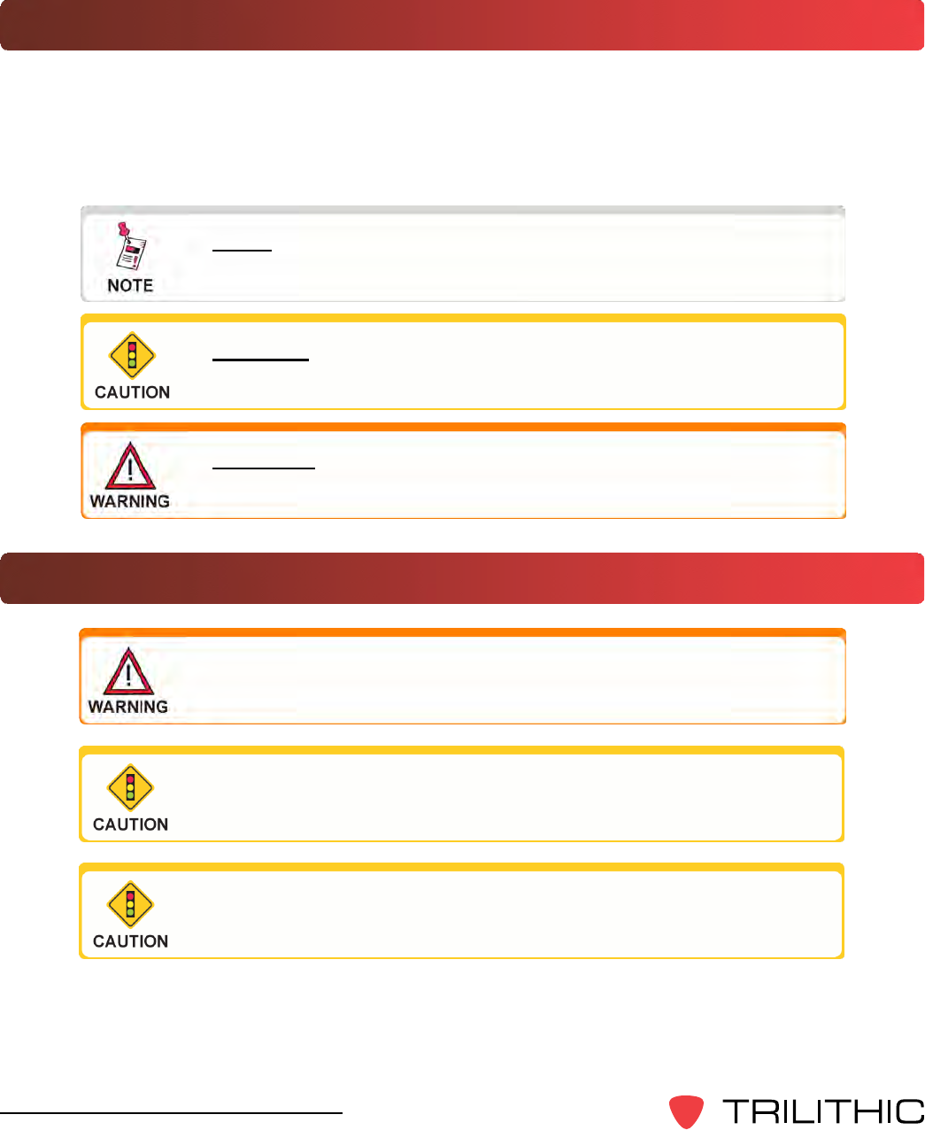
A NOTE is information that will be of assistance to you related
to the current step or procedure.
A CAUTION alerts you to any condition that could cause a
mechanical failure or potential loss of data.
A WARNING alerts you to any condition that could cause
personal injury.
Precautions
A strong electromagnetic eld may affect the accuracy of the
Seeker’s measurements.
Use only the battery charger supplied with the Seeker.
Do not use the Seeker or Seeker MCA III in any manner not
recommended by the manufacturer

13
Seeker & Seeker MCA III Operation Manual
Seeker Introduction
Chapter 2
This chapter:
• Describes the Seeker’s purpose
• Gives an overview of the Seeker’s features
• Lists the Seeker’s supplied equipment and optional accessories
• Gives a guided tour of the Seeker and Mobile Mount and explains the display screen
• Discusses the Seeker’s battery
• DiscussesupdatingtheSeeker’srmware
What is the Seeker?
TheSeekerisspecicallydesignedforefcientdistributionleakagemanagement,displaying
numerical measurements of leaks on up to ten selectable channels and emitting a tone
proportional to leak strength. The Seeker is a frequency-agile leakage detector (109.25 to
110.5 MHz and 118.50 to 147.25 MHz) with 10 user-selectable presets.
Older Seekers do not include the low band frequency from
109.25 to 110.5 MHz. Seekers that are low band frequency
compatible will have a label on the back of the device
indicating “LOW BAND ENABLED.”
The Seeker may be used in its Mobile Mount for driveouts, or removed from the mount for
leakage troubleshooting on foot with a rubber duck or optional dipole antenna.
Seeker Features
Easy Frequency Conguration
TheSeekerSetupsoftwaresimpliesthecongurationprocess.Insteadofgoingtothe
factorytomakehardwaremodications,theusercanusetheSeekerSetupsoftwareto
adjust frequencies.
14
Seeker & Seeker MCA III Operation Manual
Multiple Frequency Presets
Your Seeker can be setup to operate on up to 10 different frequency presets, which makes
iteasiertomonitorandmaintainmultiplecablesystems.Thesepresetsdenetheleakage
monitoring frequency and, if desired, the tag detection frequency as well. You have the
option of setting up only one frequency preset for simple operation, or multiple leakage
frequencies for maintaining multiple cable systems. Frequency settings range from 109.25
to 110.5 MHz and 118.50 MHz to 147.25 MHz in 6.25 kHz increments (these increments
aresufcientforusewithHRC).
Channel Tag Compatibility
Compatibility with both the Trilithic CT-2 and CT-3 channel tag devices is another feature
of your Seeker. Channel tagging refers to the process of adding frequency tags to a
broadcast channel signal. Your Seeker can be set up to detect a tagged leak and to ignore
leaks that are not tagged. With this feature, you are saved from chasing false alarms from
signals that do not originate in your system.
Channeltagvaluesrangebetween10Hzand23Hz(except16Hz)andarecongured
using the Seeker Setup software.
GT Noise Discrimination
Your Seeker works with systems employing digital set top terminals that cannot tolerate
“tagged” leakage carriers. Therefore, enhanced “false alarm” resistance can be provided
without the use of a tagged leakage signal. The Seeker analyzes the detected RF energy
and automatically detects noise and signals that are not caused by leaks from your system.
GT noise discrimination is enabled/disabled using the Seeker Setup software.
The Seeker monitors one frequency at a time. It does not
scan several frequencies at once.
Older Seekers do not include the low band frequency from
109.25 to 110.5 MHz. Seekers that are low band frequency
compatible will have a label on the back of the device
indicating “LOW BAND ENABLED.”

15
Seeker & Seeker MCA III Operation Manual
Squelch Operation
Squelch level is the RF signal threshold that the Seeker uses to determine the validity of
the signal. The signal “breaks squelch” when the RF leakage is greater than the squelch
level,aslongasanyenabledtagorGTnoisequaliersaremetaswell.Thereceiverwill
not alarm for signals below the squelch level.
Thesquelchlevelhasafactorydefaultof2µV/m.However,itcanbereconguredusing
the Seeker Setup software.
Source Localization
The Seeker emits an audible tone to help the user pinpoint the leakage source. The
tone frequency increases with signal strength. As the user moves closer to the leak, the
frequency of the tone will increase.
Vehicle Battery Protection
Overview
The Mobile Mount and Mobile Communications Adapter (MCA III) are equipped with
circuitry which automatically powers down the MCA III when the vehicle’s ignition is
turned off, only after all data upload processes have been completed. This feature
allows the vehicle to be parked and left unattended for long periods of time without
concern for depleting the vehicle’s battery. Mobile Mounts and MCA IIIs which feature
batteryprotectioncircuitryareidentiedwitha“GreenEngineering”logoonthedevice.
This feature allows a vehicle equipped with the “Green Engineering” Mobile Mount and
“Green Engineering” MCA III to automatically upload leakage data to the LAW server
application while parked and left unattended. Upon completion of the data upload
(or after a user-programmed number of attempts to upload data), the MCA III will
automatically power down. The MCA III will also stay on for a selectable time period to
avoid any “cold start” delay required by the GPS receiver after a power down.
Common leakage areas are around the tap, drop cable, and
any connection of the cable to other devices.

16
Seeker & Seeker MCA III Operation Manual
Function
Upon parking and shutting down a vehicle equipped with a “Green Engineering” Mobile
Mount and MCA III, the MCA III will attempt to upload leakage data to the LAW server
via the Wi-Fi or Ethernet connection. The MCA III will then automatically power down
after the vehicle timer delay has expired.
Seeker MCA III and Mobile Mount Compatibility
“Green Engineering” Mobile Mounts are compatible only with “Green Engineering”
Seeker MCA IIIs. Do not attempt to use an MCA III with a Mobile Mount unless both
devices feature the “Green Engineering” logo.

17
Seeker & Seeker MCA III Operation Manual
Equipment Supplied with Your Seeker
The Seeker comes with the following:
• Seeker leakage detector
• Rubber “duck” antenna
• Built-in battery
• AC travel charger and mini-USB charge / data cable
• DC power cable for the Seeker Mobile Mount
• Mobile Mount and arm with mounting hardware
• Operation manual and hardware USB driver on CD
• Printed installation guide and installation checklist
The Seeker requires a monopole antenna (not included) for
use with the mobile mount.

18
Seeker & Seeker MCA III Operation Manual
Accessories & Replacement Parts for Your Seeker
The following accessories & replacement parts are available for the Seeker:
PartNumber Description
2071679000 Rubber “Duck” Antenna
2071743000 Seeker Mobile Mount
2071585007 Power Cable for Seeker Mobile Mount
0610169007 Vehicle Power Adapter
2131249000 Seeker Holster
2071802000 Seeker Pole Mounting Kit
0610169006 Seeker Charger
0610169011 International Power Adapter Kit
2072585004 Mini-USB Data Cable
0090048000 Seeker Battery
To place an order, please call Trilithic at (800) 344-2412 or (317) 895-3600.
19
Seeker & Seeker MCA III Operation Manual
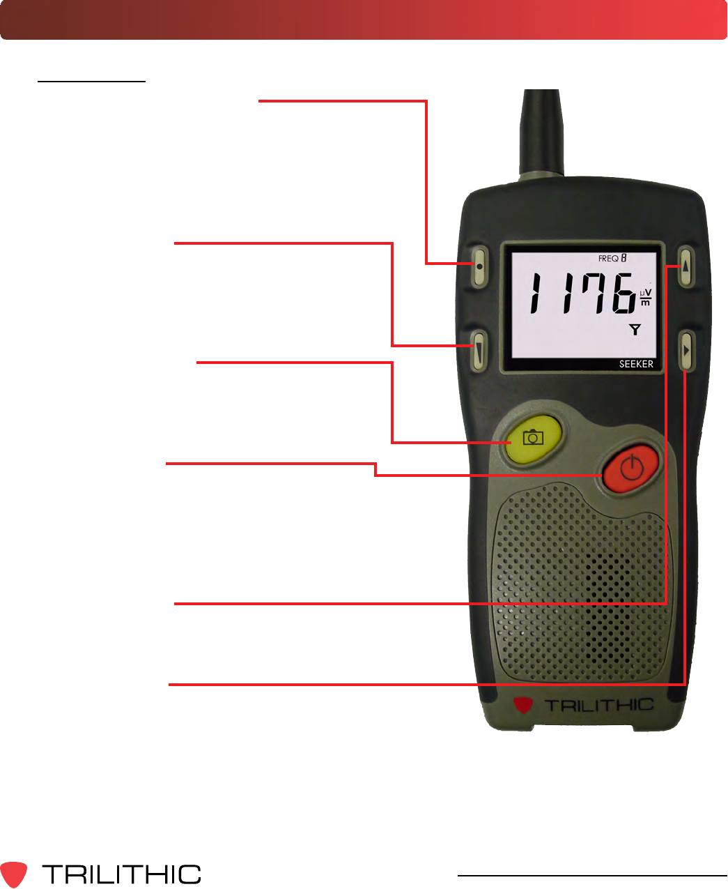
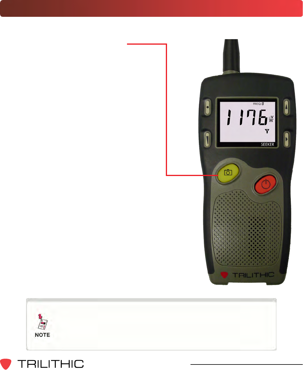
A Guided Tour of Your Seeker
Front View
AdditionalFunctionbutton
Press this button to directly enable and
disable tag detection. Also, when in
WaveTracker mode, press this button to
change the distance from the vehicle to the
cable plant.
VOLUMEbutton
Press this button to change the volume of
the leakage tone. Brief presses increase
the volume to maximum and then it rolls
over to the minimum volume.
SNAPSHOTbutton
Press this button to activate the Snapshot
mode or sync data while in the mobile
mount
ON/OFFbutton
Press and hold this button to turn the
Seeker on or off. Also, when the meter
is on, press this button to activate the
display’s backlight for approximately 60
seconds.
CHANGEbutton
Toggles or alters the current display
selection.
SELECTbutton
Press to advance to the next display mode.
20
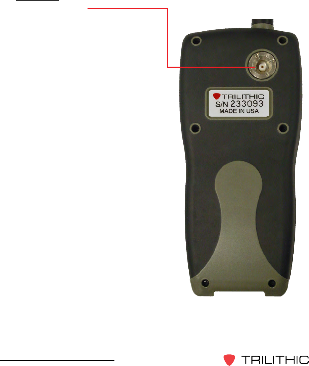
Seeker & Seeker MCA III Operation Manual
Back View
Antennaconnection
The antenna connection is used to connect
the Seeker to the Mobile Mount antenna
connection.
21
Seeker & Seeker MCA III Operation Manual
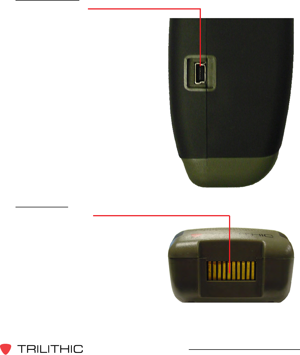
Right Side View
Mini-USBconnection
The Mini-USB connection is used to
connect the charger to the Seeker and/or
to connect a PC or laptop computer to the
Seeker using the mini-USB charge / data
cable.
Bottom View
MobileMountinterface
The Mobile Mount interface is used to
charge the Seeker as well as communicate
with the MCA III unit when the Seeker is in
the mobile mount.
22
Seeker & Seeker MCA III Operation Manual
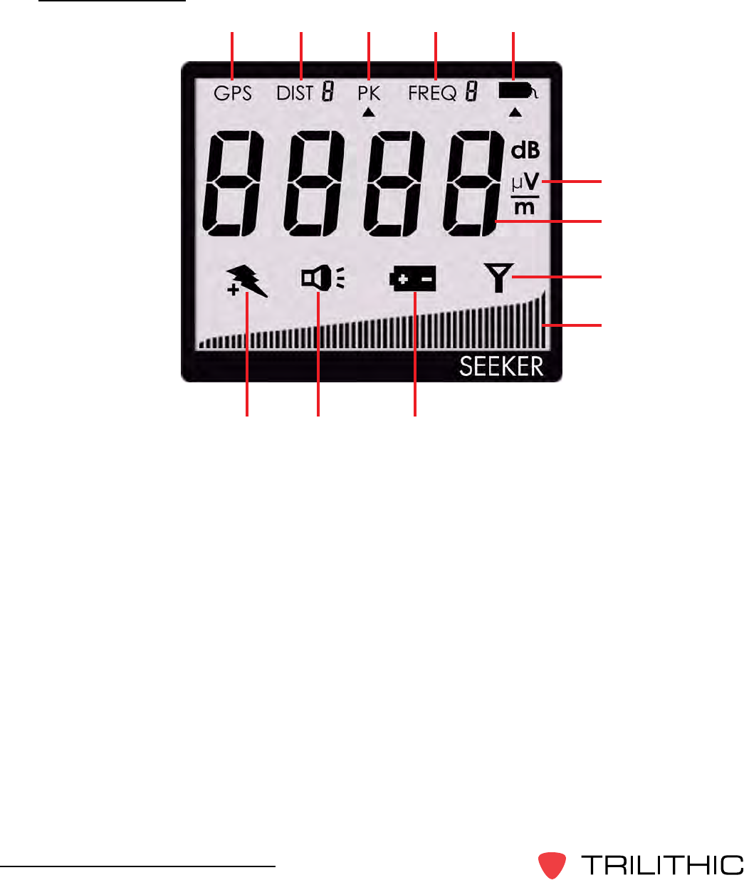
Display Screen
1. GPS - This icon is shown when the Seeker is placed in the Mobile Mount and a GPS
connection is established with the MCA III. When the icon is not shown, the Seeker is
not in the Mobile Mount or the GPS connection cannot be established with the MCA
III. If the icon blinks the MCA III is connected to the GPS but the GPS does not have a
goodpositionx.
2. DIST - This icon indicates the distance from the vehicle to the cable plant when the
Seeker is in distance corrected mode.
3. PK - This icon is shown when the Peak Hold feature is active. When the icon is not
shown, the Peak Hold feature is turned off.
4. FREQ - This icon indicates the number of the currently selected frequency preset.
5. Tag - This icon is shown when tag detection is active. The icon is not shown when tag
detection is turned off.
6. Measurement units - This indicator will show the measurement units that are selected in
SeekerSetupandtheselectediconwillblinkwhenGTnoisequaliershavebeenmet.
1 2 3 4 5
6
7
8
9
101112

23
Seeker & Seeker MCA III Operation Manual
7. Main display - This is used to show various parameters, and its function depends on the
current display mode selection.
8. Antenna - This icon blinks when the signal mode is selected. This is the normal mode
for leakage detection.
9. Bar graph - This is used to show the level of various Seeker and Seeker GPS
parameters, and its function depends on the current display mode selection.
10. Battery - This icon blinks when the battery mode is selected. The icon will stay on when
the battery needs to be recharged.
11. Speaker - This icon blinks when the volume button is pressed.
12. Charge - This icon blinks when the battery is being charged, or when the device is
placed in the Mobile Mount and the Battery Charge Level screen is displayed.
If you see any of the following messages on your display:
• The word “AP”, “CE”, “E”, or “FL” along with a number – See Chapter8:Appendix,
Display Messages & Error Codes.
• PC - Appears when the Seeker is connected to a PC and is in PC Communications
mode.
• CH - Appears when the Seeker is connected to a battery charger (AC adapter) or
a USB connection and the Seeker is not in PC Communications mode and is in
Charge mode.
• LO - Appears when Seeker’s battery is too low for the meter to function.
24
Seeker & Seeker MCA III Operation Manual
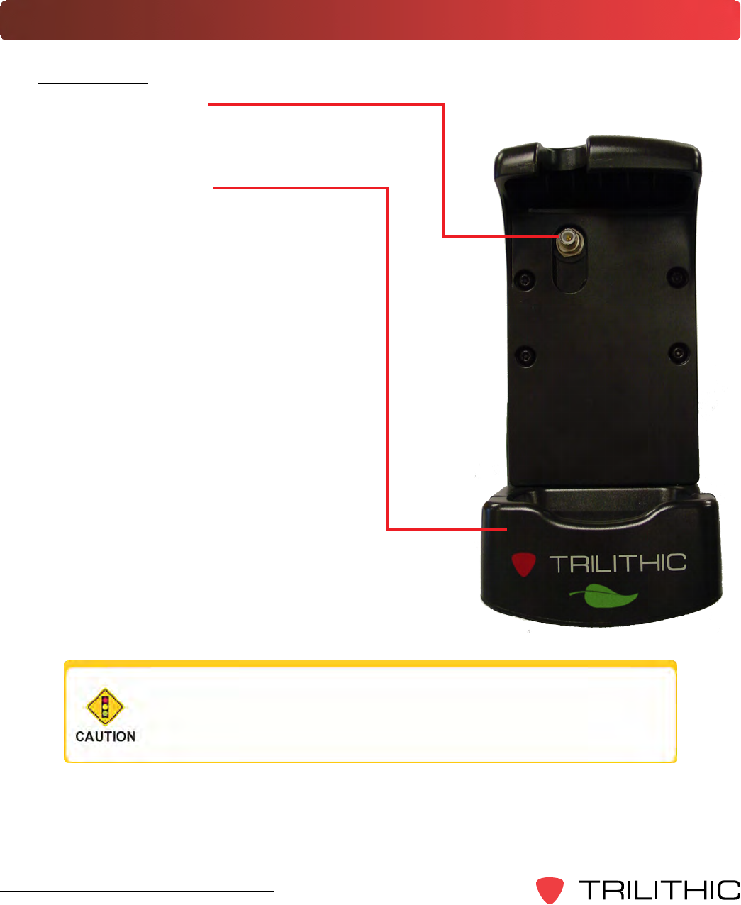
A Guided Tour of Your Mobile Mount
Front View
Antennaconnection
The Mobile Mount antenna connection is
used to connect the Seeker antenna input.
Springloadedcradle
The cradle is spring loaded to ensure that
the Seeker is held securely in the Mobile
Mount.
To place the Seeker into the Mobile Mount,
place the bottom of the Seeker in the cradle
and press down while pressing the top of
the Seeker back into the Mobile Mount to
connect the Seeker antenna input to the
mobile mount antenna connection.
The spring return of the cradle will secure
the top of the Seeker upward into the
recess in the top of the mobile mount.
If the spring return of the mobile mount cradle is broken or
not working properly, contact Trilithic at 1-800-344-2412 for
repairs.
25
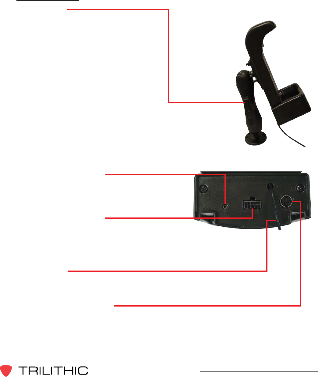
Seeker & Seeker MCA III Operation Manual
Left Side View
Mountingarm
The arm is used to secure the Mobile Mount
to the vehicle. Use the knob to tighten and
loosen the arm and then adjust the angle
of the arm to achieve the proper mounting
angle. The arm should be securely
fastened to the vehicle with four screws or
bolts.
Rear View
Audiooutputconnection
This connection is used to connect the
audio from the Seeker to an external audio
system.
MCAIIIserialconnection
This connection is used with the Mobile
Communications Adapter serial cable to
connect the Seeker Mobile Mount to the
Seeker MCA III.
Antennainput
This connection is used to connect an external monopole antenna. The rubber duck
antenna does not function when the Seeker is placed in the Mobile Mount.
DCpowercableconnection
• Red wire - Connect to an always-on positive (+) 12 Volt power supply between
the vehicle battery and the vehicle key switch
• White wire - Connect to an ignition-switched positive (+) 12 Volt power supply
• Both black wires - Connect to ground or the negative (-) battery terminal

26
Seeker & Seeker MCA III Operation Manual
About Your Seeker’s Battery
Overview
• The Seeker uses a Lithium-Ion battery. The battery is charged during manufacture
and should be ready to use as long as it has not been stored for a long period of
time.
• Lithium-Ion batteries operate differently than Nickel-Cadmium batteries. They
should be charged daily, and should not be deeply discharged as this could damage
the battery. There is no memory effect and concerns about charging too soon or
with little use are unwarranted.
If Your Seeker Does Not Turn On
• A very low battery may cause the Seeker not to turn on. Try charging the battery for
afewminutestoseeifthatxestheproblem.
Checking the Battery Level
• To check the battery level, turn your Seeker on and press the SELECT button once.
The BatteryiconwillashtoshowyouareintheBatteryChargeLeveldisplay.The
bar graph at the bottom of the display shows the amount of battery charge available.
As long as there are at least a few bars left, your Seeker has enough charge to
operate. If the battery meter shows less than 50%, the Seeker should be placed on
the charger.
• If the battery icon appears while in any of the other menus, this is a warning that the
battery is getting low and needs to be recharged soon.
• When the battery is too low for your Seeker to function, the
screen shown to the right will appear.
• Typical operating time from a full battery charge is eight
hours.
All spent batteries should be disposed of according to local
laws and guidelines.

27
Seeker & Seeker MCA III Operation Manual
Charging the Battery
AC Charging
Connecting the Mini-USB cable and charger to the Seeker will begin AC charging.
• The Mini-USB charge / data cable and charger must be connected to both the
Seeker and a working power outlet before AC charging can begin.
• When the Seeker is off and it is charging, the device will go into background
charging and nothing will be shown on the display screen.
• When the Seeker is on and is charging, the following screen will be displayed,
the Charge icon will blink, and the on-screen bar graph will show the charging
progress.
• If the Seeker is on when it is connected to a working power outlet, the device
will automatically turn off. The Seeker can be turned back on, but Measurement
mode IS disabled while the Seeker is AC charging.
USB Charging
Connecting the Mini-USB charge / data cable from a PC or laptop computer to the
Seeker will begin USB charging.
• The Mini-USB charge / data cable must be connected to both the Seeker and a
PC or laptop computer that is ON before USB charging can begin.
• When the Seeker is off and it is charging, the device will go into a background
charging and nothing will be shown on the display screen.
• When the Seeker is on and is charging, the screen above will be displayed,
the Charge icon will blink, and the on-screen bar graph will show the charging
progress.
• If the Seeker is on when it is connected to a PC or laptop computer, the device
will automatically turn off. The Seeker can be turned back on, but Measurement
mode IS disabled while the Seeker is USB charging.

28
Seeker & Seeker MCA III Operation Manual
Mobile Mount Charging
Placing the Seeker into the Mobile Mount will begin Mobile Mount charging.
• The Mobile Mount DC power cable must be connected to the Mobile Mount and
the vehicle power supply before Mobile Mount charging can begin.
• When the Seeker is off and it is charging, the device will go into a background
charging and nothing will be shown on the display screen.
• When the Seeker is on and is charging, the display will remain on the
Measurement mode screen. From the Measurement mode screen, press the
Select button once to view the on screen bar graph showing the battery charge
level. Press the Select button a second time and the charge icon will blink while
the bar graph shows charging progress.
• If the Seeker is not completely seated in the Mobile Mount, the charge screen
may not be displayed. If the Charge icon blinks but the bar graph isn’t shown,
then the Seeker is not detecting any power to the Mobile Mount. If two or more
bars are displayed, then power is present and charging is in progress.
• Measurement mode IS NOT disabled while the Seeker is mobile mount charging.
Updating Your Seeker’s Firmware
ToupdateyourSeeker’srmware,youmustusetheSeekerSetupsoftware.Formore
informationonhowtoupdateyourrmware,seetheSeekerSetupSoftwareOperation
Manual.

29
Seeker & Seeker MCA III Operation Manual
Seeker Operation
Chapter 3
This chapter:
• Provides information on Seeker’s operation and display modes
Congure Settings
YoumustconguretheSeeker’ssettingsusingtheSeekerSetupsoftware.TheSeeker
comes from the factory with default settings, but it is likely they will need to be customized.
Detailed instructions can be found in the Seeker Setup Software Operation Manual.
• ThefollowingsettingsareconguredwiththeSeekerSetupsoftware:Displayunits,
squelch, GT noise discrimination (enable or disable), the entering of leakage frequency
values, and tag frequencies. You can also use the Seeker Setup software to update
yourinstrument’srmware.
• The Tag Enable and Enable Peak Hold settings can be turned on or off using either the
Seeker Setup software or the Seeker.
• The speaker volume setting of the Seeker cannot be changed.
Seeker’s Operation Modes
Measurement Mode
Measurement Mode is used to accurately determine the strength of a leak, pinpoint its
location, and provide a leakage value for documentation. Measured RF leakage values can
range from 2 to 2000 µV/m and are displayed in large, easy-to-read numbers. A bar graph
at the bottom of the display illuminates proportionally to the signal strength of the leak.
Additionally, an audible tone will sound if the measured signal breaks squelch. The signal
breaks squelch when the RF leakage is greater than the squelch level, as long as any
enabledtagorGTnoisediscriminationqualiersarealsomet.Thistonecanbeusedto
help locate the potential source of the leak.
Enter Measurement Mode by:
Press and hold the red button until you hear three ascending tones. Within a few
moments your Seeker will begin to measure and then display ambient RF leakage.

30
Seeker & Seeker MCA III Operation Manual
PC Communications Mode
ThismodeisusedbytheSeekerSetupsoftwaretosendandretrieveconguration
parameters from your Seeker. The following screen will be displayed while your Seeker is
in this mode.
Enter PC Communications Mode by:
Connecting the Seeker to a PC or laptop computer using a mini-USB charge / data
cable and then initializing the Seeker Setup software to communicate with the Seeker.
When the Seeker is on and it is connected to a PC or laptop
computer using the Mini-USB charge / data cable, the device
will turn off.

31
Seeker & Seeker MCA III Operation Manual
Display Modes
While testing for leaks the user will need to view the information shown by the Seeker’s display
modes.
• Use the Seeker’s SELECTbutton to
toggle through its display modes.
• As you toggle, the display modes will
appear in the same order in which they
are discussed in this section.
32
Seeker & Seeker MCA III Operation Manual
Signal Level
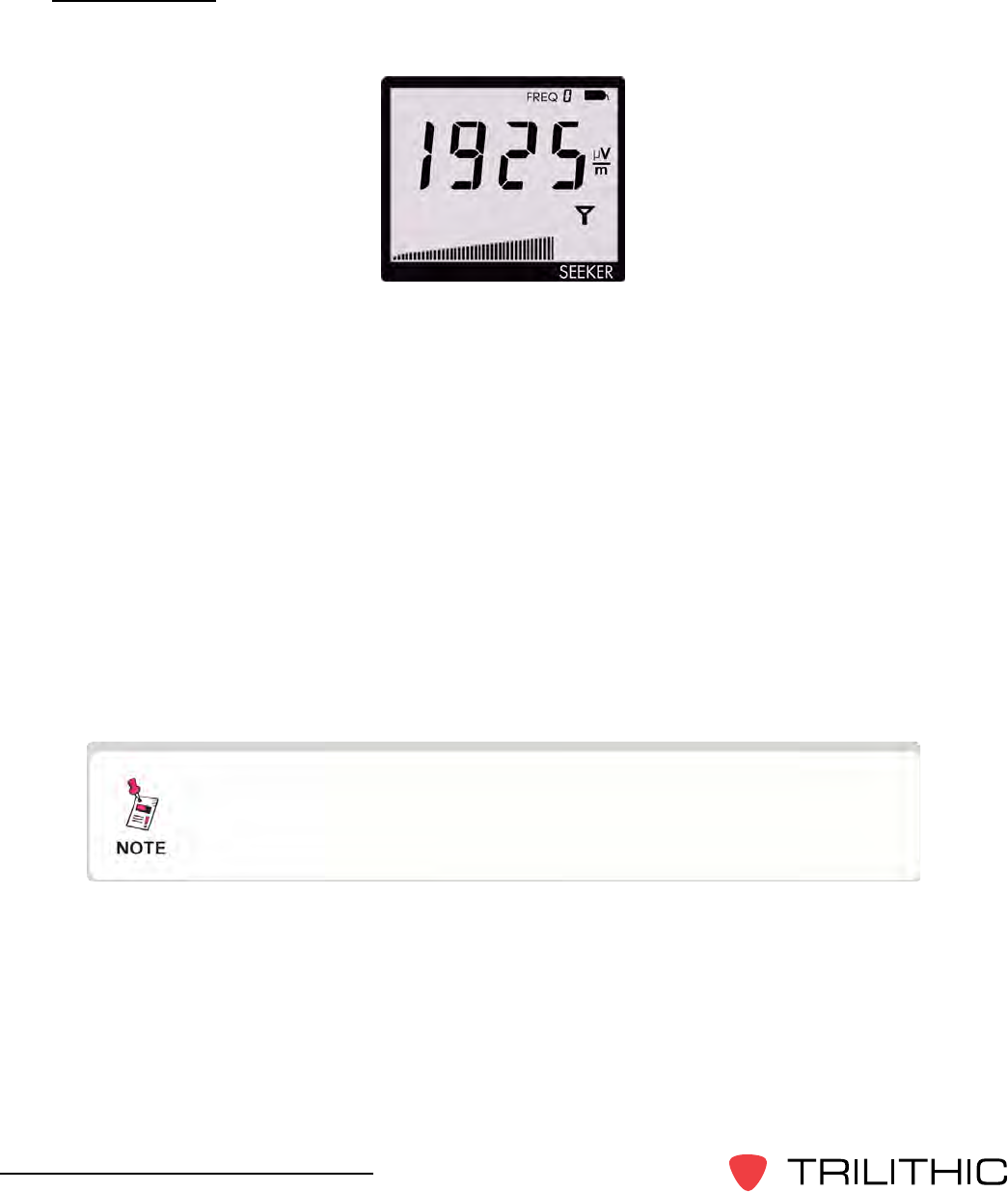
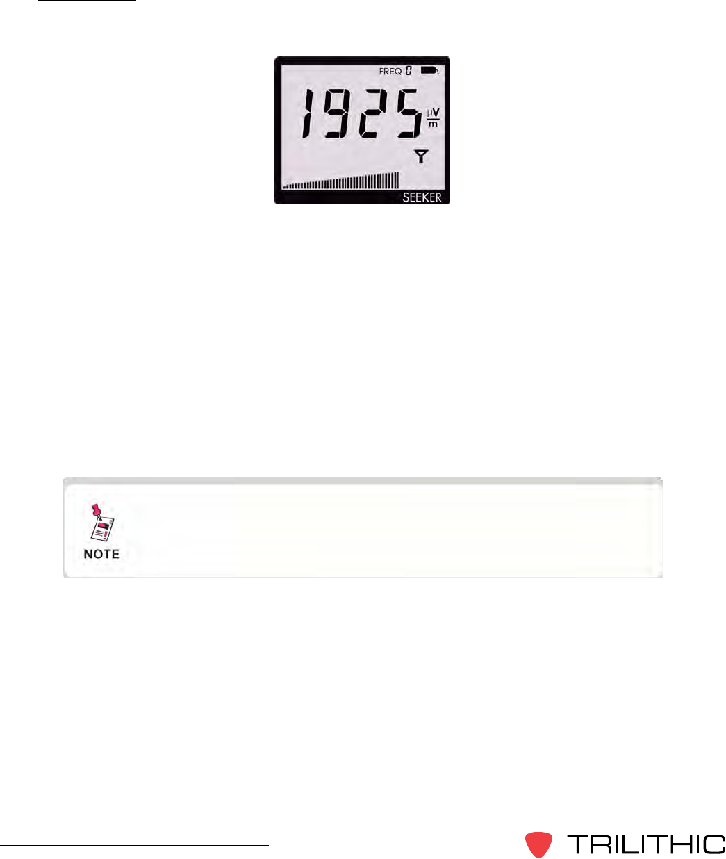
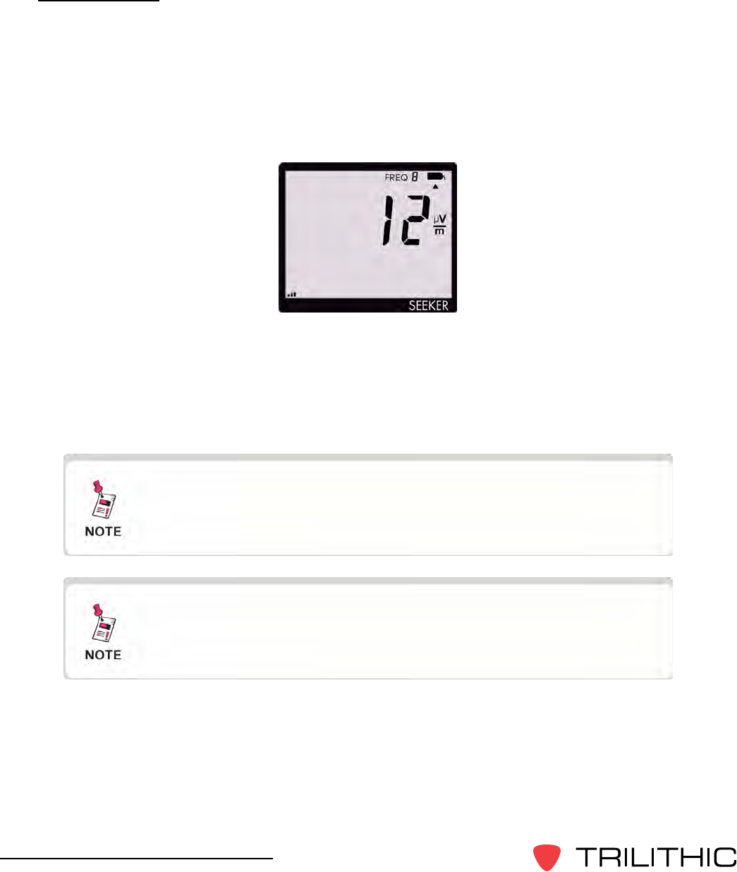
The Signal Level display is the normal display mode for leakage testing.
In this mode the Antenna icon on the display blinks to show the Signal Level display is
selected.
The signal level detected for the selected frequency will be displayed numerically and the
bar graph will indicate the relative signal level.
Also:
You can freeze the numerical display to make documenting the leakage value easier.
• To freeze the display, press the Seeker’s CHANGE button.
• To unfreeze the display, press either the Seeker’s CHANGE or SELECT button.
The display will blink to remind you it has been frozen. Even though the numerical display
doesn’t change, the bar graph will continue to update and the audible tone will still sound if
the measured signal breaks squelch.
After a few seconds in any other Display Mode without any
action by the user, the display will revert to the Signal Level
display.
33
Seeker & Seeker MCA III Operation Manual
Battery Charge Level
The Battery Charge Level display is used to test the charge level of the battery.
In this mode the Battery icon on the display will blink to show the Battery Charge Level
display is selected.
The bar graph at the bottom of the display will indicate the relative battery charge level.
The numerical display will continue to display the RF signal level.
PressingtheCHANGEbuttonwilldisplaytheSeekerFirmwareversionforveseconds.A
display of 0123 would indicate a Firmware version of 1.23.
After a few seconds in the Battery Charge Level display
without any action by the user, the display will revert to the
Signal Level display.
For detailed instructions on how to update the Seeker
Firmware, see the Seeker Setup Software Operation Manual.
34
Seeker & Seeker MCA III Operation Manual
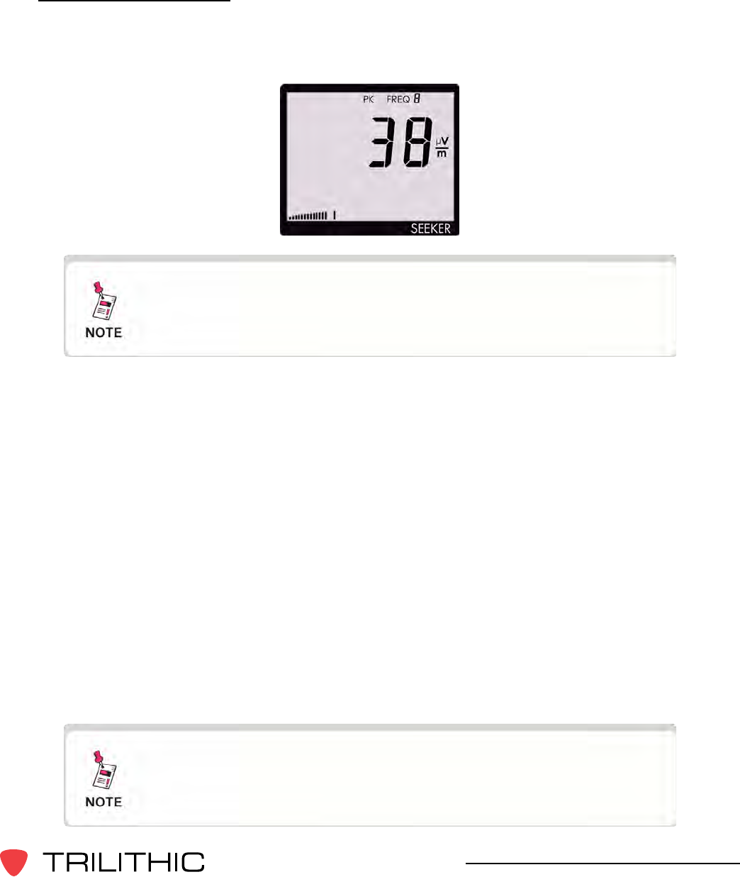
Peak Hold
The Peak Hold display is used to turn the Peak Hold function on or off.
In the Peak Hold display, the PK icon at the top of the display will blink if the Peak Hold
function is off. The “PK” symbol will be constantly displayed if the Peak Hold function is on.
Press the CHANGE button to turn the Peak Hold function on or off.
When the Peak Hold function is on, the numerical display will hold the latest peak RF level
readingforuptovesecondsunlesstheRFlevelincreases.Thisisusefulifyouarenot
abletolookatthedisplayimmediatelyorifyouwanttoconrmthehighestlevelreading.
With the Peak Hold function on, the peak element of the bar graph at the bottom of the
displaywillalsoholdit’speakindicationforvesecondswhiletheotherelementsofthebar
graph continue to indicate the signal strength of the live signal.
After a few seconds in the Peak Hold display without any
action by the user, the display will revert to the Signal Level
display.
35
Seeker & Seeker MCA III Operation Manual
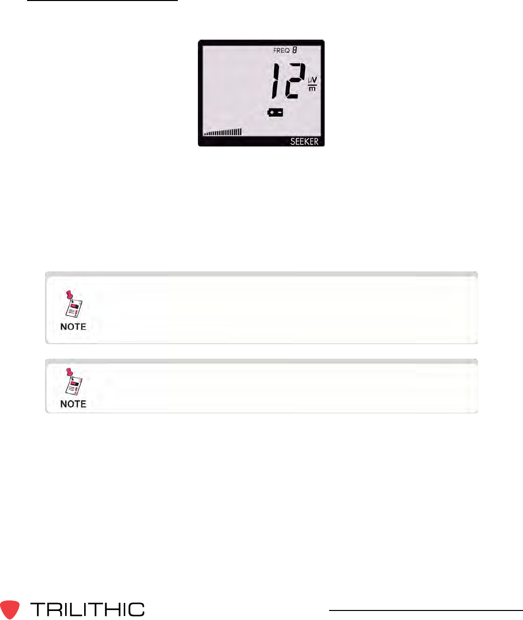
Preset Frequencies
The Preset Frequencies display is used to view the preset frequencies and select the one
used for leakage testing by the Seeker. Preset frequencies are numbered from 0 to 9 and
areconguredanddownloadedwiththeSeekerSetupsoftware.
The Seeker comes from the factory loaded with the following
preset frequencies; 121.2625, 127.2625, 133.2625, 139.2500,
and 146.2625 MHz.
After a few seconds in the Preset Frequencies display without
any action by the user, the display will revert to the Signal
Level display.
In the Preset Frequencies display, the FREQ icon at the top of the display will blink and be
followed by the preset frequency number.
To change the frequency selection, press the CHANGE button.
When entering the Preset Frequencies display or selecting a new preset frequency, the
numeric display will momentarily show the leakage frequency and tag frequency for the
preset channel. First the MHz digits will be displayed. After this, the fractional digits are
displayed. Finally a “t” is displayed followed by the tag frequency for the preset channel.
For example: For a frequency of 121.2625 MHz. with a tag frequency of 20 Hz., the display
will indicate:
121
2625
t 20
When the numerical display has cycled through the frequency information for the selected
channel, the display will resume indication of the signal level for that channel.
36
Seeker & Seeker MCA III Operation Manual
Channel Tag
The Channel Tag display is used to enable or disable the channel tag feature for the
selected frequency preset.
A Channel Tagger adds a low frequency tag (10-23 Hz, excluding 16 Hz) to a CATV
channel. When the Channel Tag feature is enabled in the Seeker, it will alarm and produce
an audible tone only when the leakage signal has the required tag. This eliminates false
alarms from signals that do not originate in the user’s system.
In the Channel Tag display, the Tag icon in the upper right corner of the display will blink if
the tag feature is not enabled. The Tag icon will be constantly displayed if the tag feature
is on.
Press the CHANGE button to turn the tag feature on or off. When the tag feature is turned
on, the display will momentarily show the tag frequency for the selected frequency preset.
The Channel Tag feature requires the installation, use, and
proper setup of the CT-2 or CT-3 Channel Tagger. It also
requires the corresponding setup of the Seeker.
After a few seconds in the Channel Tag display without any
action by the user, the display will revert to the Signal Level
display.
37
Seeker & Seeker MCA III Operation Manual
Snapshot Modes
Whiletestingforleakstheusermayneedtorecordtheprexandpostxleakageinformation
recorded by the Seeker.
Use the Seeker’s Snapshotbutton to
display the Snapshot mode. The Snapshot
modes will appear in the same order in which
they are discussed in this section.
The Snapshot button is used to synchronize data between the
Seeker and the Seeker MCA III when the Seeker is in the Mobile
Mount. For more information, see Chapter 6: Seeker MCA III
Operation, Seeker GPS Display Modes, Data Synchronization.
38
Seeker & Seeker MCA III Operation Manual
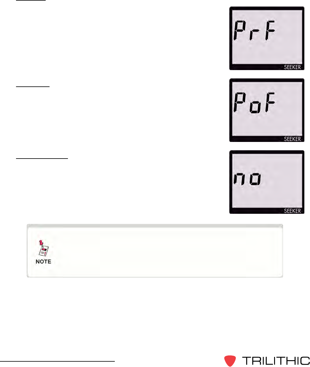
Pre-Fix
Torecordthepre-xleakageinformationrecordedbytheSeeker,
press the Snapshot button when the following screen is displayed:
Post-Fix
Torecordthepost-xleakageinformationrecordedbytheSeeker,
press the Snapshot button when the following screen is displayed:
No Snapshot
To cancel the snapshot of the information recorded by the Seeker,
press the Snapshot button when the following screen is displayed:
In Snapshot Mode, the display will cycle through the screens
displayed above until the user makes a selection. This
enables the user many opportunities to take a snapshot of the
leakage signal.

39
Seeker & Seeker MCA III Operation Manual
Leakage Testing
Chapter 4
This chapter:
• Discusses how to test for leaks using the Seeker
Before You Begin Leakage Testing
• A low battery may cause the Seeker to NOT turn on. Try charging your battery for 3
hourstoseeifthatxestheproblem,orusetheSeekerwhileinthemobilemount.
• The Seeker will retain the setup from when the meter was last shut off. For example, if
you were testing frequency preset number two and then turned off your Seeker, when
you turned it back on again the meter would automatically begin testing that same
preset.
• When turning on or changing modes on the Seeker, there is a ten (10) second delay for
the audible tone.
Testing For Leaks
TheSeekershouldbeconguredwiththeSeekerSetupsoftwarebeforebeginningleakage
testing.
1. TurnontheSeeker
Press the red on/off button until you hear 3 ascending tones. The Seeker will power up
in Measurement Mode.
2. Conrmthedesiredfrequency(0to9)isselected
IfusingtheSeekerforthersttime,thedefaultfrequencysetduringcongurationwith
Seeker Setup software will be selected.
IftheSeekerhasbeenusedsincecongurationwithSeekerSetupsoftware,thelast
frequency used will be selected.
Also,conrmtheTagFeatureisenabledordisabledasrequiredfortesting.Thiswillbe
in the state last set for the selected frequency.
For more information about using the Preset Frequency or
Channel Tag features, see Chapter 3: Seeker Operation,
Display Modes.

40
Seeker & Seeker MCA III Operation Manual
3. ConrmtheSeekerisinMeasurementmode
The Antenna icon on the display should be blinking for the Measurement mode. If
necessary use the SELECT button to move to the Measurement mode.
4. Beginleakagetesting
Move the Seeker around the test area. If the detected leakage level exceeds the
squelch level (default 2 mV/m), the Seeker will alarm.
The frequency of the alarm tone will increase as the detected signal strength increases.
Continue to move the Seeker in the direction producing the highest tone frequency to
locate the source of the leak.
5. TurnOFFtheSeeker
When testing is complete, turn off the Seeker by holding down on the red on/off button.
This step is not required if the user leaves the Seeker in the Mobile Mount.

41
Seeker & Seeker MCA III Operation Manual
Seeker MCA III Introduction
Chapter 5
This chapter:
• Describes the purpose of the Seeker MCA III
• Lists the equipment supplied with the Seeker MCA III
• Gives a guided tour of the Seeker MCA III
What is Seeker GPS?
TheSeekerGPSsystemprovidesacost-effectivewaytoequipeachvehicleinaeetwith
GPS-based reporting capabilities. The Seeker GPS system consists of the standard Seeker,
a Seeker MCA III, and a GPS receiver. The Seeker MCA III module includes a standard Wi-
Fi communications module for the wireless upload of data to the Leakage Analysis Workshop
(LAW).
Equipment Supplied with Your Seeker MCA III
The Seeker MCA III includes the following:
• P/N 2011690000 - Seeker MCA III with Wi-Fi
• P/N 2071585029 - Seeker MCA III to Mobile Mount Power and Data Cable
• P/N XXXXXXXXXX - Remote Wi-Fi Antenna
• P/N 2072213010 - CAT5e Ethernet Patch Cable - 10 Foot (Quad-Shielded)
• P/N 0500994002 - Mounting Screws (x2)
Accessories for Your Seeker MCA III
The following accessories are available for the Seeker MCA III:
• P/N XXXXXXXXXX - Garmin GPS Receiver for Seeker MCA III
• P/N 2011222000 - Seeker Approved A/B/G/N Wi-Fi Access Point
• P/N 2071585026 - Seeker MCA III Garmin Cable (FMI-15)
• P/N 2071585030 - Seeker MCA III to Wireless Matrix or SageQuest Data Cable
42
Seeker & Seeker MCA III Operation Manual
Device Overview
The Seeker MCA III is used to store leakage data collected from the Seeker and to upload the
same leakage data to the user’s PC or laptop computer or the central server.
Changes to the devices not expressly approved by Trilithic,
Inc. could void the user’s authority to operate the equipment.
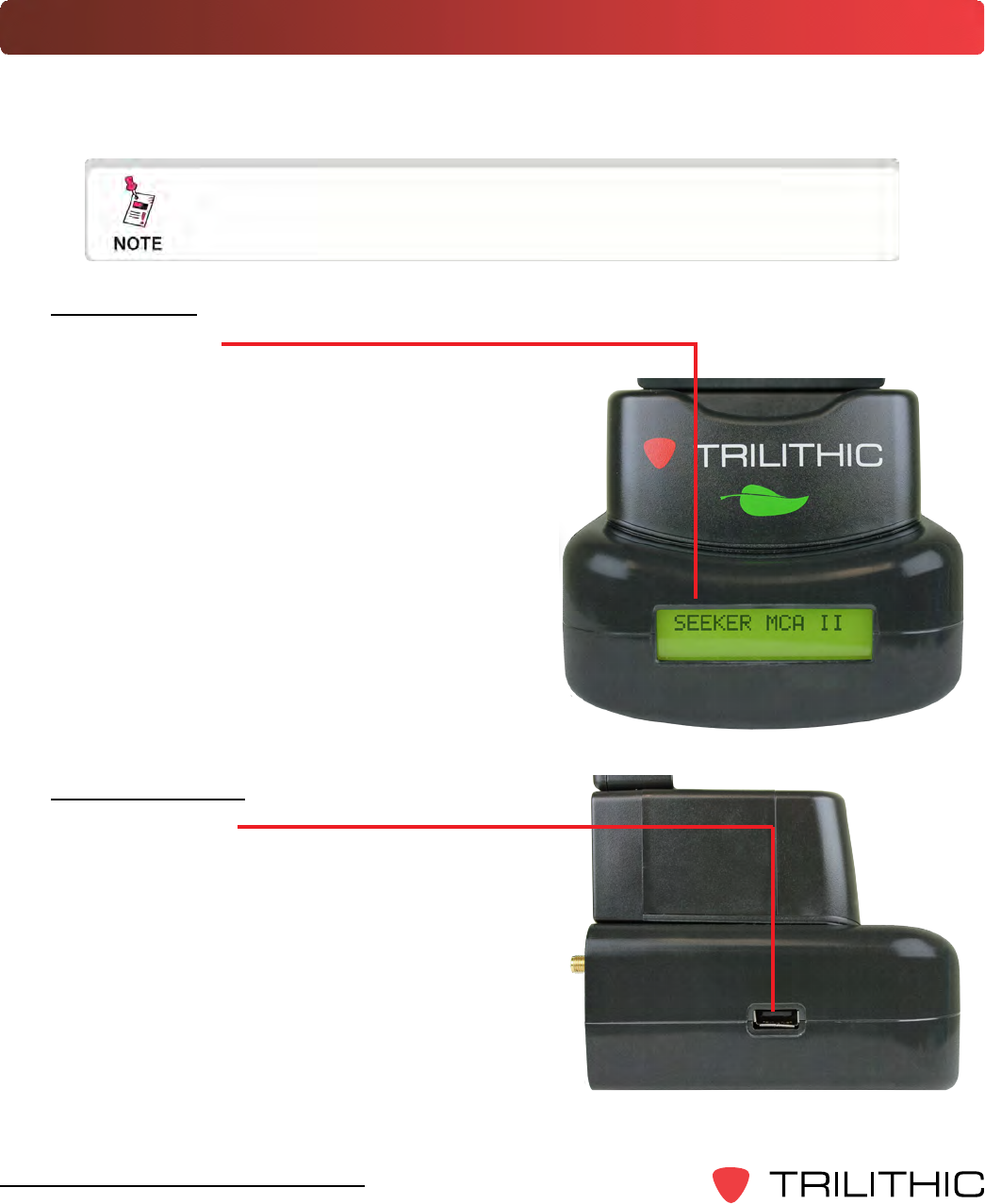
Left Side View
USBConnection
The USB connection is reserved for future use and
has no current purpose or use.
Front View
DisplayScreen
The LCD is used to display the setup and
operation status of the MCA III. The information
displayed on this screen is for reference only, the
settings shown here can be adjusted using Seeker
Setup.
43
Seeker & Seeker MCA III Operation Manual
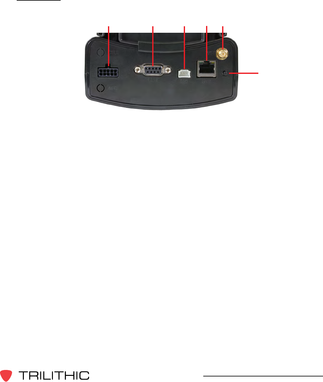
Rear View
1. Mobile Mount Serial Data Connection - This connection is used with the MCA III
serial cable to connect the Seeker Mobile Mount to the MCA III. Also, power is
supplied to the MCA III through this connection from the Mobile Mount.
2. GPS Serial Data Connection - This connection is used to connect to a serial (RS-
232) enabled GPS receiver.
3. Fleet Management Interface Connection - This connection is used to interface with
your GARMIN FMI enabled Portable Navigation Device (PND).
4. Ethernet Connection - This connection is used to connect to a LAN network in order
to upload leakage records to a LAW server.
5. Select Button - Single click this button to scroll through the device status menus and
doubleclickthisbuttontoenteraspecicstatusmenu.
6. Wi-Fi Antenna Connection - This connection is used to connect a Wi-Fi antenna in
order to transmit leakage records to a LAW server.
1 2 3 45
6

44
Seeker & Seeker MCA III Operation Manual
Display Screen Overview
The display screen of the MCA III is used to display the setup and operation status of the
unit.
Normal Display Screens
The information displayed on this screen is for reference only, the settings shown here
can be adjusted using the Seeker Setup software.
The Seeker MCA III Home Screen shows the name and version number of the installed
rmware/software.
Activity / Error Screens
If a new activity and/or error occurs within the device, the system displays a popup
message to indicate the type of activity and then returns to the previous screen after 10
seconds. If a new activity or error occurs prior to expiration of the 10 seconds, then the
new message will be displayed and the 10 seconds will start again. The only exceptions
to this rule are the Wi-Fi, Cellular, and Ethernet Upload In Progress screens which will
remain on the screen until the upload is complete, an error occurs, or the Select button
is single clicked.
Using the Select Button
To navigate the display screens, perform the following actions using the Select button
on the back of the MCA III:
Single click the Select button to scroll through the device status menus,
indicated by blue lines and the symbol shown to the left or dismiss any
popup messages related to device activity and/or errors.
DoubleclicktheSelectbuttontoenteraspecicstatusmenu,
indicated by red lines and the symbol shown to the left.
45
Seeker & Seeker MCA III Operation Manual
Seeker MCA III Operation
Chapter 6
This chapter:
• Lists recommended software
• Provides information on Seeker GPS operation and display modes
Congure Settings
YoumustconguretheMobileCommunicationAdapter(MCAIII)settingsusingtheSeeker
Setup software. The MCA III comes from the factory with default settings, but it is likely they
will need to be customized. Detailed instructions can be found in the Seeker Setup Software
Operation Manual.
Ensure that the Seeker is properly seated in the Mobile Mount,
otherwise the Seeker will display an error message and it will
not be able to communicate with the Seeker MCA III .
Seeker GPS Display Modes
Mobile Mount Communication Successful
After placing the Seeker in the mobile mount and upon successful communication with the
MCA III the Seeker will momentarily show the following display.
For detailed instructions on how to update the MCA II
Firmware, see the Seeker Setup Operation Manual.
46
Seeker & Seeker MCA III Operation Manual
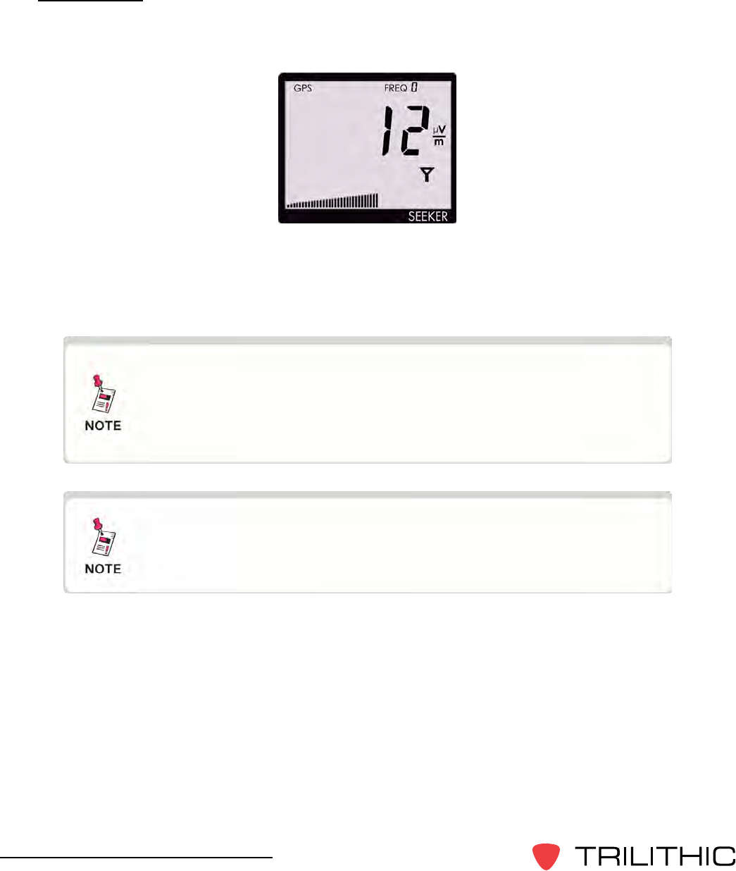
GPS Signal
When the Seeker is placed in the Mobile Mount, the GPS Signal display is used to display
the status of the GPS Signal.
When the GPS receiver is off, the text GPS icon is not shown on the display.
When the GPS receiver is on but the GPS receiver IS NOT receiving a satellite signal, the
GPS icon will blink.
When the GPS receiver is on and the GPS receiver IS receiving a satellite signal, the GPS
icon will be on constantly.
When the GPS receiver IS NOT receiving a satellite signal, the
MCA III will not record leakage data from the Seeker nor will it
be able to communicate with TechPoint for FMI updates.
When the GPS receiver has been off or has not been able
to receive a satellite signal, for more than ve minutes, the
device will beep twice every few seconds until the condition is
corrected.
47
Seeker & Seeker MCA III Operation Manual
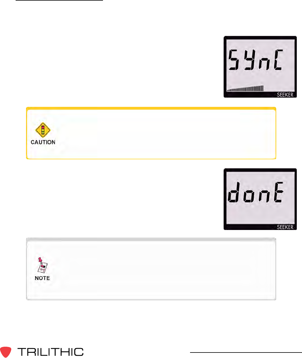
Data Synchronization
When a user does not have a Wi-Fi or cellular connection available to upload recorded data
from the MCA III to the central server, the user may synchronize the data of the MCA II with
the internal memory of the Seeker.
To synchronize the data between the MCA III and the Seeker, press
and hold the Snapshot button. While the MCA III is transferring
data to the Seeker, the Seeker will display the following screen:
When the MCA III is done transferring data to the Seeker, the
Seeker will display the screen to the right. Press any button to
return to the Measurement display.
The bar graph will show the progress of the data
synchronization, do not remove the Seeker from the Mobile
Mount until the data synchronization is completed, otherwise
data corruption will occur.
This mode will only work when the Seeker is in the Mobile
Mount. The Snapshot button is used to record the pre x and
post x leakage information recorded by the Seeker when the
Seeker is not in the Mobile Mount. For more information, see
Chapter 3: Seeker Operation, Snapshot Modes.

48
360 DSP Operation Manual
THIS PAGE LEFT INTENTIONALLY BLANK

49
Seeker & Seeker MCA III Operation Manual
Data Upload Options
Chapter 7
Standard Internet Connection
The leakage data can be uploaded via an Internet connection. The user removes the Seeker
from its Mobile Mount and connects it to a PC or laptop computer. The leakage data is then
uploaded to the central server using a website on the internet.
Wi-Fi
The leakage data can be uploaded via a wireless connection. Whenever the user’s vehicle is
parked for a user determined duration in a user determined upload position/zone within range
of an authorized wireless hotspot, the leakage data is uploaded directly to the central server.
Fleet Management System Integration
ForeetsequippedwithGPS-basedeetmanagementsystems,thereal-timeleakage
data can be automatically uploaded directly to the central server through the truck’s cellular
connection via the MCA III ethernet connection.

50
360 DSP Operation Manual
THIS PAGE LEFT INTENTIONALLY BLANK

51
Seeker & Seeker MCA III Operation Manual
Appendix
Chapter 8
General Specications
FrequencyRange
Settable using Seeker Setup Software, in 6.25 kHz steps.
LowBand: 109.25 to 110.50 MHz
HighBand: 118.50 to 147.25 MHz
Older Seekers do not include the low band frequency from 109.25
to 110.5 MHz. Seekers that are low band frequency compatible
will have a label on the back of the device indicating “LOW BAND
ENABLED”.
Frequency
Presets 10 user-set operating frequencies, selectable on front panel.
Selections are loaded into the detector using Seeker Setup software.
LevelRange 2 to 2000 mV/M. Can freeze current numeric reading or hold peak
readings.
Numerical
Display LCD readout of any detected leakage within sensitivity range.
AudibleTone Tone is present if leakage amplitude exceeds squelch setting. Pitch
is proportional to strength of leak.
Leakage
Sampling&
RecordingRate
33 times/second sampling, 1 record/second continuous logging.
ChannelTag
Range 10 Hz to 23 Hz (Excluding 16 Hz)
Power Built-in Lithium-ion battery
OperationTime
MeasurementMode: Eight hours, typical
ChargeTime: Less than three hours for full-charge in the mobile
mount, six hours for charging using the mini-USB connection.
Dimensions 7.48 x 3.43 x 1.85 in (190 x 87 x 47 mm)
Weight 0.95 lbs (431 g)

52
Seeker & Seeker MCA III Operation Manual
Display Messages & Error Codes
Seeker Error Codes
The codes shown below are displayed on the Seeker display
screen as “E##” to indicate an error with the Seeker.
“E##”
Code ErrorDescription Solution
01 Factory 1 Parameters
The checksum is not valid for this area or the
calibration date for this area is not set. Factory 1
contains the filter, level, and GT calibration items. If
a power cycle does not fix this, return to the factory
for recalibration.
02 Factory 2 Parameters
The checksum is not valid for this area or the
calibration date for this area is not set. Factory 2
contains the temperature calibration items. If a
power cycle does not fix this, return to the factory for
recalibration.
03 Bad Identity The identity voltage read does not correspond to a
known configuration. If a power cycle does not fix
this, return to the factory for repair.
04 Temperature Calibration
Trigger
There was an error re-writing the temperature
calibration trigger pattern when starting the
temperature cal cycle. The meter probably needs to
be retriggered by CalibrATE.
05 Temperature Calibration
Write
An error occurred while writing values during the
temperature calibration cycle. Power cycling the
meter will probably return back to the “”THnn””
display and start the temp cal cycle over again.
06 Factory 2 Parameters
Pending
This happens when the meter is power-cycled after
the temperature calibration cycle has completed, but
CalibrATE has not yet read and checked the results.

53
Seeker & Seeker MCA III Operation Manual
“E##”
Code ErrorDescription Solution
07 Sync Error
A problem occurred during a hot sync from an
MCA back into a meter. This is most likely a
communication error with the MCA. Try the sync
process again.
08 Bad Flash ID
The flash ID read did not correspond to either the
ST M25P64 or Winbond W25X64 device. If a power
cycle does not fix this, then return to the factory for
repair.
09 RTC Error
The RTC power-on test failed (the value read from
a RAM location in the RTC did not match the value
written). If a power cycle does not fix this, then return
to the factory for repair.
10 Pairing Error An error occurred during the meter/MCA pairing
process. Retrigger the meter for pairing and try
again.
11 Pairing Error The meter is not paired with the connected MCA. If
they are the correct meter and MCA, then retrigger
the meter for pairing and try again.

54
Seeker & Seeker MCA III Operation Manual
MCA III Error Codes
The codes shown below are displayed on the Seeker
MCA III display screen or on the MCA III display screen as
“DEVICE ERRORS” to indicate an error with the MCA II.
“E##”
Code ErrorDescription Solution
0 No errors detected N/A
3Factory Calibration is
not valid Return the device to the factory for repair.
4User Parameters are
not valid UseSeekerSetuptorecongurethedevice.
7Invalid Flash ID
detected Cycle power on the unit, if the error persists return
the device to the factory for repair.
8 Flash memory is Full Use any of the means available to either erase the
data, synchronize to the meter, or move the data to a
valid LAW connection.
9Flash memory write
failed If the error persists, return the device to the factory
for repair.
10 Wi-Fi Post failed If the error persists, return the device to the factory
for repair.
11 Wi-Fi module
communications failed If the error persists, return the device to the factory
for repair.

55
Seeker & Seeker MCA III Operation Manual
“E##”
Code ErrorDescription Solution
12 WEP key
communications failed Check to ensure that your WEP key is valid and
recongurethedeviceusingthecorrectWEPkey.
13 WPA key
communications failed
Check to ensure that your WPA/WPA2 key is valid
andrecongurethedeviceusingthecorrectWPA/
WPA2 key.
14 WiFi signal level
communications failed If the error persists, contact support as this error may
requirearmwareupdatetocorrect.
30 Flash memory erasure
error If the error persists, return the device to the factory
for repair.
31 Cellular modem
communications error
If the error persists, contact support as this error
mayrequirearmwareupdatetocorrect.Iftheerror
persists, return the device to the factory for repair.
32 Cellular connection
could not obtain an IP
If the error persists, contact support as this error
mayrequirearmwareupdatetocorrect.Iftheerror
persists, contact your cellular data provider for further
support.
33
Cellular connection
could not establish a
network socket to the
desired end point
Check to ensure that your connection settings are
correctandrecongurethedeviceusingthecorrect
information.
34 No data erasure
command received from
LAW after data upload
Ifthiserrorpersists,contactsupporttoconrmthat
your LAW server is set up correctly.
35 Upload stopped
Ethernet communications attempt caused an upload
to be postponed. Information only, uploading was
postponed due to a Seeker Setup connection
attempt.

56
Seeker & Seeker MCA III Operation Manual
“E##”
Code ErrorDescription Solution
36 Wi-Fi Association Failed Check the Wi-Fi information and ensure that the
securitykeysarecorrectandrecongurethedevice
using the correct Wi-Fi settings.
37 Wi-Fi DHCP Request
Failed
Could not obtain an IP address using DHCP, if
enabled. Verify that the Access Point has a DHCP
server enabled or has a route to a network DNCHP
server.
38 Wi-Fi DNS request
failed
Check the IP information and ensure that the DNS
serversarecorrectandrecongurethedeviceusing
the correct Wi-Fi settings.
39
Wi-Fi connection could
not establish a network
socket to the desired
end point
Check to ensure that your connection settings are
correctandrecongurethedeviceusingthecorrect
information.
40 UndenedWi-FiError If the error persists, return the device to the factory to
repair.
41
Ethernet connection
could not establish a
network socket to the
desired end point
Check to ensure that your connection settings are
correctandrecongurethedeviceusingthecorrect
information.
42 External FMI connection
communications error If the error persists, return the device to the factory to
repair.
43 Ethernet DNS request
failed
Check the IP information and ensure that the DNS
serversarecorrectandrecongurethedeviceusing
the correct Ethernet settings.
44 Ethernet connection
failure If the error persists, contact support as this error may
requirearmwareupdatetocorrect.

57
Seeker & Seeker MCA III Operation Manual
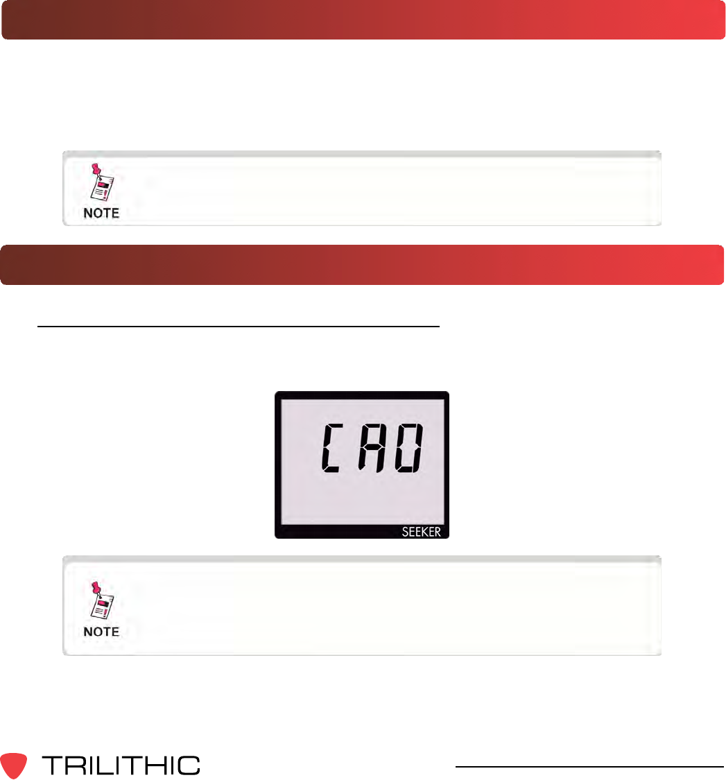
“AP##”
Code ErrorDescription
00 Displayed for 3 seconds at power on when this mode has been activated. Also
displayed (could be for minutes) while the Wi-Fi module is being set up and
associating with the access point for testing of a new zone.
01 There was a communications problem between the Seeker and the MCA.
02 The Wi-Fi module returned a Power On Self Test error.
03 There was no access point association for the selected zone.
04 TherewasnoIPdenedfortheselectedzone(noDHCP?)
05 There was a problem communicating to the Wi-Fi module.
06 The Wi-Fi module rejected the WEP key for the selected zone.
07 The Wi-Fi module rejected the WPA key for the selected zone.
08 The selected home zone has not been enabled.
09 The selected home zone has not been enabled for Wi-Fi.
99 Undenederror-thisindicatesarmwarebug.
Access Point Error Codes
The codes shown below are displayed on the Seeker display
screen as “AP##” to indicate an error with the access point.
58
Seeker & Seeker MCA III Operation Manual
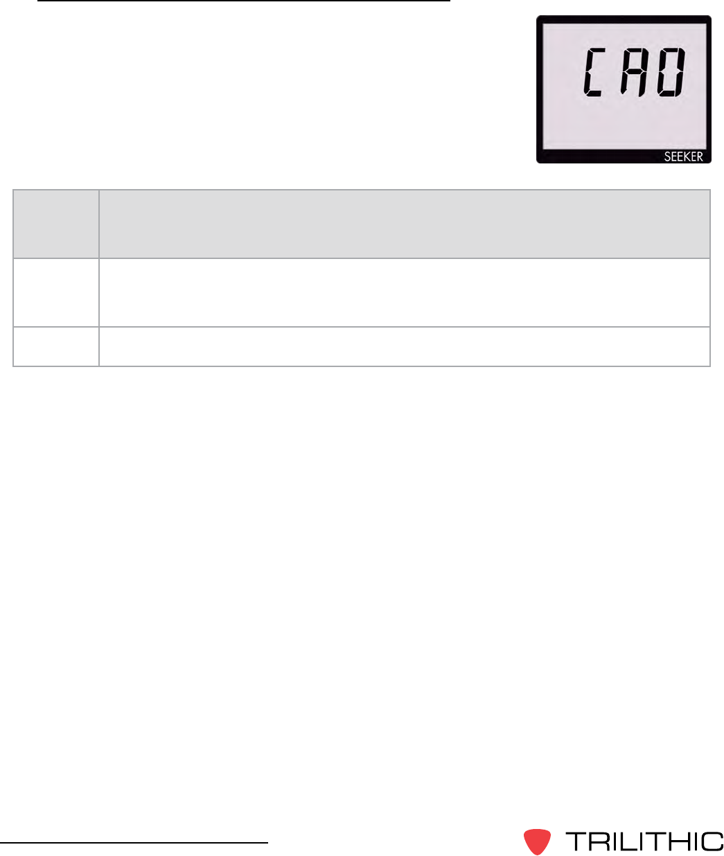
Seeker & MCA II Communication Messages
The codes shown below are displayed on the Seeker display
screen as “CA#” to indicate the communication status between the
Seeker and MCA II.
“CA##”
Code ErrorDescription
0 The Seeker meter has successfully established a connection to an MCA.
1 The Seeker meter is in the process of “syncing” snapshots to the MCA memory.

59
Seeker & Seeker MCA III Operation Manual
Seeker & MCA II Memory Full Messages
The codes shown below are displayed on the Seeker display
screen as “FL#” to indicate the internal memory status of the
Seeker and MCA II.
“FL##”
Code ErrorDescription
0MCA internal memory is full. Shows after “CA0” if there are less than 30,000
records available. This display is cleared by a button press on the Seeker meter,
which will cause a 1 hour “snooze” until the FL0 message is displayed again.
1Seeker internal memory is full. Shows at power-on if there is not enough room
for at least an 8-hour day’s worth of data (30,000 records). Shows at sync time if
there is not enough room to store the MCA contents in the meter memory.
2Seeker “snapshot” memory is full - needs to be cleared with Seeker Setup or
docked to transfer snapshots to an MCA.

60
360 DSP Operation Manual
THIS PAGE LEFT INTENTIONALLY BLANK

61
Seeker & Seeker MCA III Operation Manual
Trilithic Broadband Instruments 2-Year Limited Warranty
Trilithic, Inc. (“Trilithic”) warrants to the buyer that the product will be free from defects in materials and
workmanship, under normal use, operating conditions and service for a period of two (2) years from date of
delivery. Trilithic reserves the right, before having any obligation under this limited warranty, to inspect the
damaged product, and all costs of shipping the product to Trilithic for inspection shall be borne solely by the
buyer. Trilithic’s obligation under this limited warranty shall be limited, at Trilithic’s sole option, to replacing or
repairing the product, or to replacing or repairing any defective part, F.O.B. Indianapolis, Indiana. If neither of the
two options is reasonably available, then Trilithic, in its sole discretion, may provide a prorated refund to the buyer
of the purchase price of the product, as evidenced by the proof of purchase, less any applicable service fees in
accordance with the following schedule: months 0-3 = 100%; months 4-12 = 50%; and months 13–24 = 25%.
Batteries and fans are not included or covered by this limited warranty. Any product or part that is repaired or
replaced under this limited warranty shall be covered only for the remainder of the original warranty period which
applied to the original product or part, or for ninety (90) days, whichever is longer. All products or parts that are
exchanged for replacement shall become the property of Trilithic.
In order to recover under this limited warranty, buyer must make a written claim to Trilithic within sixty (60) days
of the occurrence and must present acceptable proof of original ownership of the product (such as an original
receipt, purchase order or similar documentation). In order for this limited warranty to be effective, the product
must have been handled and used as set forth in the documentation accompanying the product and/or its
packaging.Thislimitedwarrantyshallnotapplytoanydamageduetoaccident,misuse,abuse,neglect,reor
other casualty. Further, this limited warranty shall not apply to any product which has been altered or where the
damagewascausedbyapartnotsuppliedbyTrilithic.Trilithicretainsthenaldecisionwhetheraproductis
within warranty conditions.
THE REMEDY SET FORTH HEREIN SHALL BE THE ONLY REMEDY AVAILABLE TO THE BUYER AND
TO THE FULLEST EXTENT PERMITTED BY LAW, IN NO EVENT SHALL TRILITHIC BE LIABLE FOR ANY
SPECIAL, INCIDENTAL, PUNITIVE OR CONSEQUENTIAL DAMAGES, INCLUDING BUT NOT LIMITED
TO, LOST REVENUES, LOST PROFITS, LOSS OF USE OF SOFTWARE, LOSS OR RECOVERY OF DATA,
DOWNTIME, REPLACEMENT EQUIPMENT AND ANY THIRD PARTY CLAIMS ARISING OUT OF ANY THEORY
OF RECOVERY INCLUDING WARRANTY, CONTRACT, STATUTORY OR TORT IN CONNECTION WITH
THE PRODUCT, EVEN IF TRILITHIC HAS BEEN ADVISED OF THE POSSIBILITY OF SUCH DAMAGES.
NOTWITHSTANDING THE FOREGOING, IN THE EVENT THAT THIS LIMITED WARRANTY FAILS OF ITS
ESSENTIAL PURPOSE, IN NO EVENT SHALL TRILITHIC’S ENTIRE LIABILITY TO BUYER EXCEED THE
PURCHASE PRICE OF THE DEFECTIVE PRODUCT.
EXCEPT FOR THE LIMITED WARRANTY PROVIDED HEREIN, TO THE FULLEST EXTENT PERMITTED
BY LAW, TRILITHIC DISCLAIMS ALL WARRANTIES, EXPRESSED OR IMPLIED (INCLUDING WITHOUT
LIMITATION, ANY IMPLIED WARRANTIES OF MERCHANTABILITY OR FITNESS FOR A PARTICULAR
PURPOSE), WITH RESPECT TO THE PRODUCT OR ITS SUITABILITY FOR ANY USE INTENDED FOR IT BY
THE BUYER. TO THE EXTENT ANY IMPLIED WARRANTIES MAY NONETHELESS EXIST BY OPERATION OF
LAW, ANY SUCH WARRANTIES ARE LIMITED TO THE DURATION OF THIS LIMITED WARRANTY.
This limited warranty is non-transferable. This limited warranty does not affect any other legal rights buyer may
have by operation of law. No agent, reseller, distributor or business partner of Trilithic is authorized to modify the
terms of this limited warranty on behalf of Trilithic.

9710 Park Davis Drive
Indianapolis, IN 46235
(317) 895-3600
www.trilithic.com
P/N 00103XXXXX 6/13 Made in U.S.A.