Trilliant Networks SC3130 802.11 Based, Fixed Wireless Node User Manual
Trilliant Networks, Inc. 802.11 Based, Fixed Wireless Node
User Manual

SkyPilot
SkyAccess DualBand
Installation
Contents
About This Guide 5
1 Overview
Features and benefits 7
About access point configuration 7
SkyPilot network topology 8
2 The SkyAccess DualBand Installation Kit 13
What the kit provides 14
What else you need 14
Getting help 16
3 Installing a SkyAccess DualBand 17
Planning your installation 17
Cabling the SkyAccess DualBand 18
Powering on the SkyAccess DualBand 20
Optimizing location 22
Mounting the SkyAccess DualBand 24
Connecting to the wireless network 27
Configuring the SkyAccess DualBand 29
A Accessing SkyAccess DualBand Command-Line Interfaces 31
Connect to the SkyAccess interface 31
Connect to the access point interface 32
B Specifications 37

About This Guide
This guide explains how to install and set up a SkyPilot™ SkyAccess™
DualBand that provides access to a SkyPilot wireless mesh network and serves
as an access point for users of 802.1x wireless (Wi-Fi).
This guide assumes administrator-level knowledge of IP networks and a
familiarity with configuring wireless devices.
SkyPilot SkyAccess DualBand Installation 6

SkyPilot SkyAccess DualBand Installation 7
Overview
SkyAccess DualBand is a dual-radio solution that combines SkyPilot’s
long- range, high-capacity 4.9 GHz mesh backhaul with a high-powered
802.11b/g access point that lets service providers and municipalities offer
standard Wi-Fi to subscribers.
Features and benefits
SkyAccess DualBand provides a highly flexible wireless solution that
combines scalable Wi-Fi capacity with the seamless coverage of a
wireless mesh network.
Each SkyAccess DualBand can support multiple WLANs (wireless local
area networks), each with its own VLAN and security policy. One
SkyAccess DualBand can support several business models with a single
service installation.
About access point configuration
The SkyAccess DualBand access point is set up to provide Wi-Fi access
right out of the box. The access point includes a preconfigured WLAN
with the SSID (service set identifier) SkyAccessDualBand, providing
WPA-PSK (Wi-Fi protected access – pre-shared key) protection. Users
attempting to connect to the SkyAccessDualBand WLAN must provide
a password (publicpublic by default). The default configuration is
provided for initial management and configuration of the SkyAccess
DualBand access point via a wireless connection. You should always
create a unique access point configuration before testing the device or
making it available to customers.
1
SkyPilot SkyAccess DualBand Installation 8
NOTE A wireless network protected by WPA-PSK is vulnerable. To
provide a more secure level of protection, configure the WLAN
for WPA authentication in which each user is authenticated
separately.
SkyPilot network topology
SkyPilot Networks™ delivers a wireless, end-to-end broadband solution
that seamlessly supports high-capacity, high-coverage mesh networks.
Designed for managed-access networks and service providers, the
SkyPilot network takes broadband wireless the “last mile” with a cost-
effective, robust infrastructure solution.
Based on a high-performance architecture that deploys intelligent
antenna arrays, the SkyPilot network delivers a dynamic broadband
solution with significant advantages for business and home users.
SkyPilot wireless devices are simple to install and easily fit into any type
of wireless environment—metropolitan, business, or home.
The auto-discovery and rapid provisioning features of a SkyPilot wireless
mesh network greatly reduce deployment and maintenance costs.
Support for multiple topologies and high scalability allow attractive
options for rapidly expanding a metro Wi-Fi customer base.
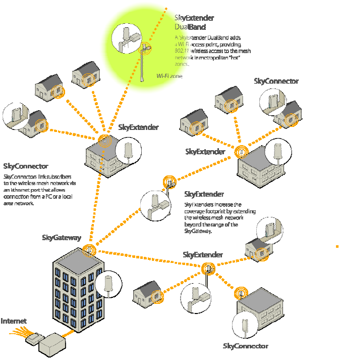
A SkyPilot network (as illustrated in Figure 1) may include the following
physical components:
SkyGateway™ (required)
SkyExtender™
SkyExtender™ DualBand
SkyConnector™ Indoor
SkyConnector™ Outdoor
SkyAccess™ DualBand
SkyPilot SkyAccess DualBand Installation 9
Figure 1. SkyPilot wireless mesh network
SkyGateway
The SkyGateway operates as a base station for a wireless mesh
network. It provides an interface between wired infrastructure and a
wireless network of subscribers who enjoy secure, high-speed access to
the Internet or to wide area networks (WANs).
A SkyPilot wireless network requires at least one SkyGateway for normal
operation. If necessary, you can add additional SkyGateways to increase
network capacity or provide redundancy.
The SkyGateway typically resides at a location with easy access to wired
infrastructure—usually a POP (point of presence) or data center.
SkyPilot SkyAccess DualBand Installation 10
For optimal performance, install the SkyGateway on an elevated site
such as a cell tower or the top of a tall building.
SkyExtender and SkyExtender DualBand
SkyExtenders and SkyExtender DualBands provide a cost-effective way
to add capacity and balance network loads, by operating as “repeaters”
to extend the wireless range of a SkyGateway (see Figure 1). You can
add these devices to your network to expand your coverage footprint and
provide redundancy through SkyPilot’s mesh networking features. (A
SkyExtender can also provide subscribers with a direct connection to the
wireless network via its Ethernet port.)
In addition, the SkyExtender DualBand serves as a Wi-Fi access point,
enabling service providers and municipalities to provide standard 802.11
wireless access across great distances, for targeted hot zones, or for
dense coverage patterns.
For optimal performance, install the SkyExtender in an elevated location
such as a roof, tower, or utility pole.
SkyConnector and SkyAccess DualBand
SkyConnectors link your subscribers to the SkyPilot wireless network. An
Ethernet port on the SkyConnector enables a connection to be
established to the subscribers’ computers, or to a local area network
(LAN) via a data switch or router. For flexibility of installation, SkyPilot
offers indoor and outdoor versions of the SkyConnector.
Designed for installation by the service provider, the outdoor version of
the SkyConnector attaches to an external structure such as an eave,
roof, or pole. Because it provides a better line of sight to the SkyGateway
or a SkyExtender, the outdoor SkyConnector generally offers greater
range than the indoor unit.
The indoor version of the SkyConnector is a plug-and-play network
device that a subscriber can easily install without technical assistance.
Service providers should advise subscribers to place the SkyConnector
SkyPilot SkyAccess DualBand Installation 11
in a location with an optimal sight line to the SkyGateway or a
SkyExtender.
SkyAccess DualBand offers the same features as a SkyConnector, plus
a Wi-Fi access point that allows service providers and municipalities to
provide standard 802.11 wireless access across great distances, for
targeted hot zones, or for dense coverage patterns.

SkyPilot SkyAccess DualBand Installation 13
The SkyAccess DualBand
Installation Kit
The SkyPilot SkyAccess DualBand kit provides everything you need to
install the device and configure it as both a connector to your wireless
mesh network and an 802.11b/g Wi-Fi access point.
This chapter reviews that equipment and tells you what else you need to
have on hand before starting installation.
NOTE Professional Installation is required for ensuring that the
proper antenna is employed so that the limits in this
part are not exceeded.
2
SkyPilot SkyAccess DualBand Installation 14
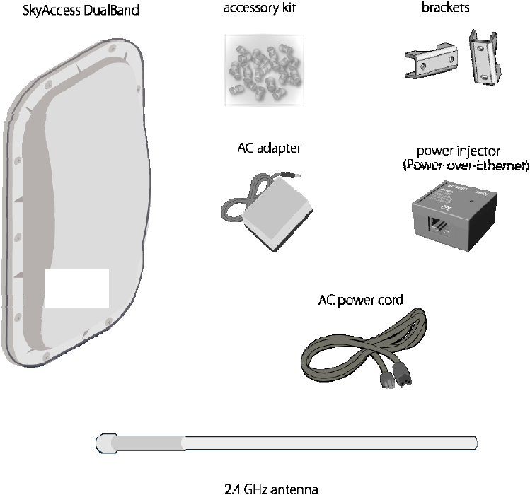
What the kit provides
Figure 2. Contents of SkyAccess DualBand installation kit
SkyPilot also offers accessories, including a tilt mount for optimizing your
SkyAccess DualBand installation. For more information, contact a
SkyPilot sales representative.
NOTE The 4.9 GHz antenna is integrated into the dualband connector
housing. The 2.4GHz antenna is the external antenna.
What else you need
Before starting installation, you also need the following:
4.9 GHz
Antenna
SkyPilot SkyAccess DualBand Installation 15
For basic mounting: A Phillips screwdriver
For pole mounting:
A magnetic level (optional)
A secured steel pole between 1.13" (2.87 cm) and 1.37"
(3.48 cm) in diameter
For network cabling:
A spool of CAT5 network cable (shielded cable is
recommended)
NOTE Ethernet cabling must comply with the requirements
of NEC/CEC codes for outdoor CAT5 cables. The
outer jacket of the cabling must be clearly marked
as CAT5e per ANSI/TIA/EIA-568-B.2.
Ethernet crossover cable (for connecting to data switch or
router)
RJ-45 connectors (connectors without a protective “boot”
are recommended)
RJ-45 crimping tool
For wireless mesh network configuration: A laptop with a Telnet client
application and a 10/100bT Ethernet network interface card
Setup information for the access point:
A (case-sensitive) wireless SSID for each virtual WLAN
Wi-Fi network
A unique IP address for the management of the access
point if it’s not connected to a DHCP server
A default gateway and subnet mask for the management
network if the access point is not on the same subnet as
your PC
NOTE Plan on configuring the SkyAccess DualBand before mounting it.
Some steps are easier if the access point is more accessible.
SkyPilot SkyAccess DualBand Installation 16
Getting help
For technical assistance, contact SkyPilot support by logging in to
customer support at www.skypilot.com.

SkyPilot SkyAccess DualBand Installation 17
Installing a SkyAccess DualBand
This chapter provides instructions for planning and performing the
physical installation of a SkyAccess DualBand.
Planning your installation
In a typical wide area wireless mesh network, you’ll install a SkyAccess
DualBand on a utility pole or the roof of a building. The effective range of
the SkyAccess DualBand is usually proportional to the height of the
installation.
When choosing a site for the device, consider the radio frequency (RF)
environment and physical characteristics of the site.
Trees, buildings, and hills can block a wireless signal. Also keep in mind
that the RF environment is dynamic and can deteriorate over time as
obstacles appear or are relocated.
Plan on testing potential sites to determine the suitability of the link
topology for target applications. Once you’ve identified a potential site,
use a topographic map or path profile software to ensure that terrain or
obstacles will not interfere with the links.
Your site survey should include an RF scan to identify available
frequencies. You should also check your preferred frequency at all
locations; a frequency that’s clear at one location may be crowded at
another. Frequency planning is a critical factor in planning and
implementing a wireless mesh network.
3
SkyPilot SkyAccess DualBand Installation 18
The site survey process should be ongoing. To verify that a site is
relatively free of interference, make site audits every 6 to 12 months,
scheduling regular maintenance visits to coincide with the site audits.
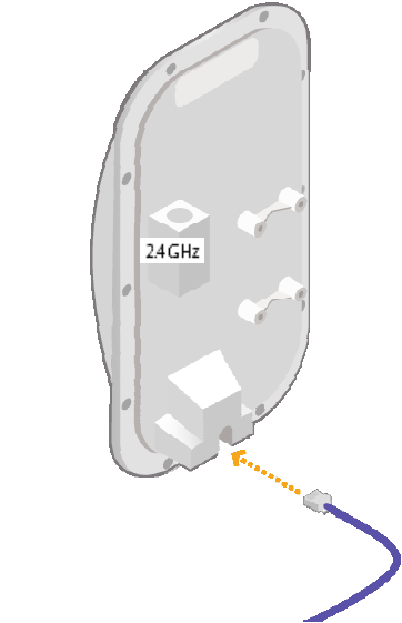
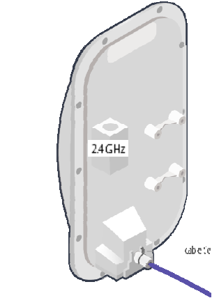
Cabling the SkyAccess DualBand
Ethernet cabling provides both power and data connectivity for the
SkyAccess DualBand.
The section provides instructions for attaching CAT5 cable to the device.
1 Terminate the appropriate grade and length of CAT5 cable with an
RJ-45 connector and plug it into the RJ-45 port on the back of the
SkyAccess DualBand.
Figure 3. Connecting CAT5 cable to the SkyAccess DualBand
Make sure the fit is snug so that the cable does not interfere with the
weather gasket.
4.9 GHz
SkyPilot SkyAccess DualBand Installation 19
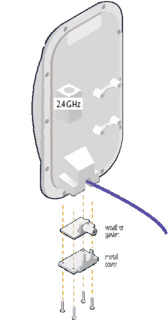
2 Insert the weather gasket and secure the metal cover.
Press the CAT5 cable into the gasket and insert the gasket into the
housing, taking care not to twist or place unnecessary force on the
RJ-45 connector.
Fit the metal cover over the weather gasket and secure it with the
four machine screws supplied in the accessory kit.
Figure 4. Attaching weather gasket and metal cover
4.9 GHz
SkyPilot SkyAccess DualBand Installation 20
4 Attach tie wraps to the neck of the weather gasket and tighten them
so that they slightly depress the neck.
Figure 5. Attaching tie wraps to the gasket neck
The tie wraps provide relief from cable strain and ensure a fully
weatherproof seal.
Powering on the SkyAccess DualBand
Before mounting the SkyAccess DualBand, first power on the unit so that
you can use the onboard LEDs to determine optimal placement.
1 Connect the SkyAccess DualBand to the power supply, as follows:
a. Plug the AC adapter into an AC outlet.
b. Connect the Ethernet cable to the port labeled “CPE” on the
power injector.
c. Plug the AC adapter into the power injector.
4.9 GHz
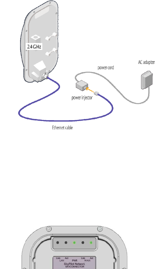
SkyPilot SkyAccess DualBand Installation 21
Figure 6. Providing power to the SkyAccess DualBand
2 Check the LEDs on the SkyAccess DualBand.
If the connections are correct, the power LED (labeled “PWR”) and
the WAN activity LED (labeled “WAN Act”) on the SkyAccess
DualBand will illuminate. The WAN Act LED should blink and turn off,
but the PWR LED should remain lit.
Figure 7. Checking the SkyAccess DualBand LEDs
4.9 GHz
SkyPilot SkyAccess DualBand Installation 22
Optimizing location
After powering on the SkyAccess DualBand, use the device’s LEDs to
identify the optimal location for mounting—a location where it can easily
acquire a signal from the wireless mesh network and quickly create links.
Confirm signal acquisition
Position the SkyAccess DualBand near the intended mounting
location and watch the WAN Act LED for activity.
The LED starts to blink when it has acquired a signal from the
network and is attempting to set up a connection.
If the WAN Act LED does not start blinking within 30 seconds, try
changing the orientation of the SkyAccess DualBand or walk to a new
location; then repeat the process until the LED begins blinking.
When the LED starts blinking, make minor adjustments to find the
location where the signal is strongest. (The faster the LED blinks, the
stronger the signal.)
When the WAN Act LED blinks steadily and at a high rate, you have
an optimal signal. Go to the next section to verify the network
connection.
Verify network connection
Watch the WAN Link LED for activity.
Within approximately 90 seconds of locating a signal, the WAN Link
LED should start to blink—first slowly, then more quickly.
When the WAN Link LED is solid and the WAN Act LED is blinking,
the SkyAccess DualBand has established an authorized connection
to the network, indicating that the current location is suitable for
mounting
If both the WAN Act LED and the WAN Link LED continuing blinking,
a signal is available but is not strong enough for reliable service.
Keep trying different locations until you can confirm a network
connection.
SkyPilot SkyAccess DualBand Installation 23
NOTE To optimize your SkyAccess DualBand installation, ask your
network administrator (at the Network Operations Center) to
measure signal strength on the node to which the SkyAccess
DualBand has established a link.
For more information on LED states, see Table 1.

SkyPilot SkyAccess DualBand Installation 24
Table 1. SkyAccess LED states
LED LED state Device state
LAN Link Steady illumination SkyAccess DualBand is connected to
another device via its Ethernet port.
LAN Act Blinking Device is transmitting or receiving
data via its Ethernet port.
PWR Steady illumination Device is powered on.
WAN Link Blinking (fast blink
when device is in
standby mode)
Device is attempting to establish an
authorized connection on the wireless
network.
If both WAN Link and WAN Act
continue to blink, the signal is not
strong enough to support reliable
service or there is a provisioning
problem that’s preventing the device
from coming online. Contact your
network administrator.
Steady illumination Device is connected to the wireless
network.
WAN Act None Device cannot detect a wireless
network.
Blinking Device is within the coverage area of
a wireless network. Blink rate
communicates signal strength:
• Fast (8x per second) = excellent
• Medium (4x per second) = good
• Slow (<1x per second) = poor
• None = no reception
Mounting the SkyAccess DualBand
After determining an optimal location for your SkyAccess DualBand, you
can mount the device and run the appropriate cables.
SkyPilot SkyAccess DualBand Installation 25
Before mounting the device, disconnect the CAT5 cable from the power
injector to power down the device.
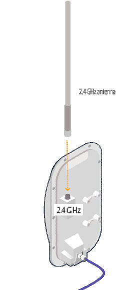
1 Connect the 2.4 GHz antenna.
To provide Wi-Fi connectivity, the SkyAccess DualBand requires
attachment of the 2.4 GHz antenna included with the device. Screw
the antenna onto the standard N connector on the back of the
SkyAccess DualBand.
Figure 8. Attaching the 2.4 GHz antenna.
2 Use the supplied clamps to secure the SkyAccess DualBand to the
pole; then loop the Ethernet cable around the mounting pole and
secure it with tie wraps.
4.9 GHz
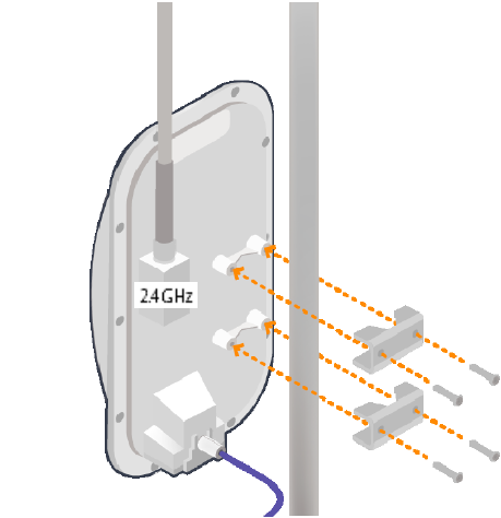
SkyPilot SkyAccess DualBand Installation 26
Figure 8. Securing the SkyAccess DualBand
Tighten the bolts securely on the mounting hardware.
3 Reconnect the CAT5 cable to the port on the power injector to
restore power to the SkyAccess DualBand.
4.9 GHz
SkyPilot SkyAccess DualBand Installation 27
Connecting to the wireless network
After mounting the SkyAccess DualBand, you can set up a connection to
the wireless network via a local computer or LAN. Once connected, a
subscriber can use the wireless network to gain access to Internet
services and applications.
You can connect to the SkyAccess DualBand with Ethernet, or use the
onboard access point to establish a wireless connection.
Connect to the wireless network with
Ethernet
Connect the device to a computer or LAN (for a SkyAccess DualBand
that’s providing Internet/WAN access to the mesh network).
Connect a second Ethernet cable from the power injector port labeled
“Computer” to a personal computer or router/data switch providing a
connection to a LAN.
SkyPilot SkyAccess DualBand Installation 28
Figure 9. Connecting a SkyAccess DualBand to a computer
Connect to the wireless network via a Wi-
Fi connection
1 From a Wi-Fi/WPA-PSK capable computer within operating range of
the access point, open the Network control panel and set up a
wireless connection with the IP address 192.168.0.10 and Netmask
255.255.255.0.
2 From the Network Connection control panel choose the default SSID
provided with the SkyAccess DualBand— SkyAccessDualBand.
3 At the password prompt, enter publicpublic.
4.9 GHz

SkyPilot SkyAccess DualBand Installation 29
Configuring the SkyAccess DualBand
A SkyAccess DualBand requires two different configurations: a network
configuration that allows it to operate on the wireless mesh network, and
an access point configuration that allows the device to support local
wireless connections via Wi-Fi.
For information about configuring both the device and the access point,
see the document SkyPilot Network Administration, available
in electronic format from the SkyPilot website at
www.skypilot.com/support/.
4

SkyPilot SkyAccess DualBand Installation 31
Accessing SkyAccess DualBand
Command-Line Interfaces
This appendix describes how to access the command-line interfaces that
SkyPilot SkyAccess DualBand provides for provisioning and
troubleshooting. You can connect to two different interfaces on the
SkyAccess DualBand: an interface with the device that operates as a
node on the wireless mesh network, and a separate interface with the
access point that extends Wi-Fi connectivity to subscribers.
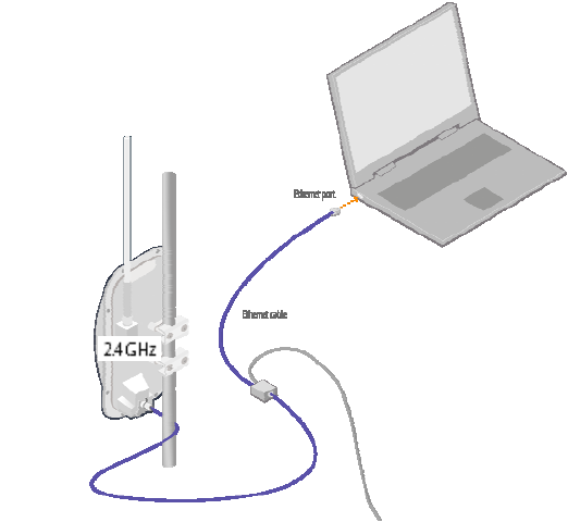
Connect to the SkyAccess interface
You can connect to a SkyAccess DualBand and access the command-
line interface through Telnet over an Ethernet connection. After logging in
(by supplying a password), you can enter commands at the command
prompt.
1 Mount and cable the SkyAccess DualBand according to the
instructions in Chapter 3.
2 Prepare a PC or laptop.
Open the network settings panel and assign the computer the IP
address 192.168.0.3 with a subnet mask of 255.255.255.0.
3 Connect the computer to the SkyAccess DualBand according to the
instructions in Chapter 3 (see on page Error! Bookmark not
defined.).
4 Start a Telnet session.
A
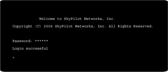
SkyPilot SkyAccess DualBand Installation 32
Telnet to the default IP address of the SkyAccess DualBand
(192.168.0.2).
5 Log in by entering the password at the command prompt. (The
default is public.)
Figure 11. Example Telnet login
After making an Ethernet connection to the SkyAccess DualBand, you
can manage and troubleshoot the device using a wide range of
commands available through the command-line interface. For detailed
descriptions of the commands, as well as sample output for many of
them, see SkyPilot Network Administration.
For comprehensive guidelines to troubleshooting devices on your
SkyPilot wireless mesh network, see Getting Started with the
SkyPilot Network.
Connect to the access point interface
You can connect to the access point command-line interface via Telnet
over a wireless network connection. (Typically, you will use this technique
to confirm the IP address of the access point component of the SkyPilot
DualBand.)
1 Prepare a PC or laptop.
You will need a Wi-Fi/WPA-PSK capable computer that’s within
operating range of the access point and a Telnet application you can
use to open a connection between the devices.
SkyPilot SkyAccess DualBand Installation 33
The access point component of SkyAccess DualBand ships with the
default IP address 192.168.0.3.
2 Open the connection to the access point.
From your Telnet application, open a connection to the access point.
3 Log in by entering the default user name (admin) and password
(public) at the command prompt.
Once you’re logged in, you can use the command-line interface to set
configuration parameters or retrieve the IP address of the access
point

SkyPilot SkyAccess DualBand Installation 34
FCC Regulatory Information
FCC Radio Frequency Interference Statement
This equipment has been tested and found to comply with the limits for a
Class B digital device, pursuant to Part 15 of the FCC Rules. These limits
are designed to provide reasonable protection against harmful
interference in a residential installation. This equipment generates, uses
and can radiate radio frequency energy and, if not installed and used in
accordance with the instructions, may cause harmful interference to radio
communications. However, there is no guarantee that interference will
not occur in a particular installation. If this equipment does cause harmful
interference to radio or television reception, which can be determined by
turning the equipment off and on, the user is encouraged to try to correct
the interference by one or more of the following measures:
o Reorient or relocate the receiving antenna.
o Increase the separation between the equipment and receiver.
o Connect the equipment into an outlet on a circuit different from
that to which the receiver is connected.
o Consult the dealer or an experienced radio/TV technician for help.
B
SkyPilot SkyAccess DualBand Installation 35
The user of this product is cautioned that changes or modifications made
to the equipment without the approval of the manufacturer void the user's
authority to operate the equipment.
FCC Radiation Exposure Limits
To comply with FCC RF exposure requirements in section 1.1307, a
minimum separation distance of 40 cm (16 inches) is required between
the antenna and all persons.

SkyPilot SkyAccess DualBand Installation 37
Specifications
This appendix provides technical specifications for the SkyPilot
SkyAccess DualBand.
Wireless Specifications
Frequency bands capable
US & Canada
For other countries check with
sales representative
4.950 - 4.980 GHz.
Wi-Fi Access: 2.412 - 2.462 GHz
EIRP 29 dBm/0.9 W peak,
Wi-Fi Access: 35.0 dBm / 3.2 W
Media access Time Division Duplex (TDD)
Modulation technique OFDM with adaptive modulation
Wi-Fi Access: DSSS and OFDM
Modulation rates 6–54 Mbps
Throughput Up to 20 Mbps UDP, up to 10 Mbps TCP
Latency 8–10 ms roundtrip per hop
Antennas 28° horizontal x 9° vertical panel, 17 dBi
Wi-Fi Access: omnidirectional 9 dBi antenna
C

SkyPilot SkyAccess DualBand Installation 38
with diversity
Channel width 20 MHz
Channel resolution 5 MHz frequency control
Receive sensitivity -90 dBm at 6 Mbps modulation
Connectivity SkyAccess DualBand connects with
SkyGateways, SkyExtenders, and SkyExtender
DualBands
Authentication MD5-based certificates
Encryption 128-bit AES on all wireless links
Product Specifications
Connectors RJ-45: Ethernet connection (10/100bT) and
power (Power-over-Ethernet)
Mounting Eave, roof, or chimney; outside pole diameter
up to 2.0"
Range 7.5 miles (12 km)
Wi-Fi Access: Up to 1,200 feet
LEDs Wireless activity, wireless link, LAN activity,
LAN link, and power
Dimensions 12.6" (32 cm) H x 6.6" (16.8 cm) W x 4.2" (10.7
cm) D
Weight 3.8 pounds (1.7 kg)
Operating temperature -40° to 131° F (-40° to 55° C)
Wind loading Up to 150 mph (240 km/h)
Enclosure/humidity NEMA-4X
Power 110–230 VAC, 50–60 Hz input; 8 W

SkyPilot SkyAccess DualBand Installation 39
Certifications FCC Part 9, FCC 47 CFR Part 15, Class B
USA; compliance with UL safety standards,
EMI and susceptibility FCC Part 15.107 and 15.109
Warranty One-year limited warranty on hardware and
software
Security
Authentication MD5-based certificates
Encryption AES
Filtering Based on protocol type, IP port ID, and
configurable IP address list
VLAN Supports 802.1q VLAN tagging; supports a
management VLAN for managing traffic and a
data VLAN for subscriber traffic
Network Management
Command-line interface Console via Telnet
NMS integration SNMP v2c
GUI configuration SkyProvision™ software and Web interface
GUI EMS SkyControl™ software
IP address DHCP or static
Firmware Multiple versions of firmware stored in
nonvolatile memory; updated via FTP
Configuration file XML over HTTP

SkyPilot SkyAccess DualBand Installation 40
Quality of Service
Prioritization 802.1p-based; based on protocol type, IP
address, port ID, and configurable IP address
list
Traffic shaping Per-device rate limits upstream and
downstream
Monitoring and MIB Support
Supported MIBs MIB-II (RFC 1213); EtherLike (RFC 2665);
Bridge (RFC 1493); SkyPilot private MIB
Local management RS-232 Serial Console Port
Remote management Command-line interface via Telnet, SNMP v2c,
Web interface
Topology
Configurations Mesh, point-to-multipoint, point-to-point