Trilliant Networks SC4110 DUAL BAND 802.11 abg FIXED WIRELESS NODE User Manual sys arch pro guide2
Trilliant Networks, Inc. DUAL BAND 802.11 abg FIXED WIRELESS NODE sys arch pro guide2
UserManual.wiki
>
Trilliant Networks
>
SC4110 User Manual
>
Manual 3
Contents
1.
Manual 1
2.
Manual 2
3.
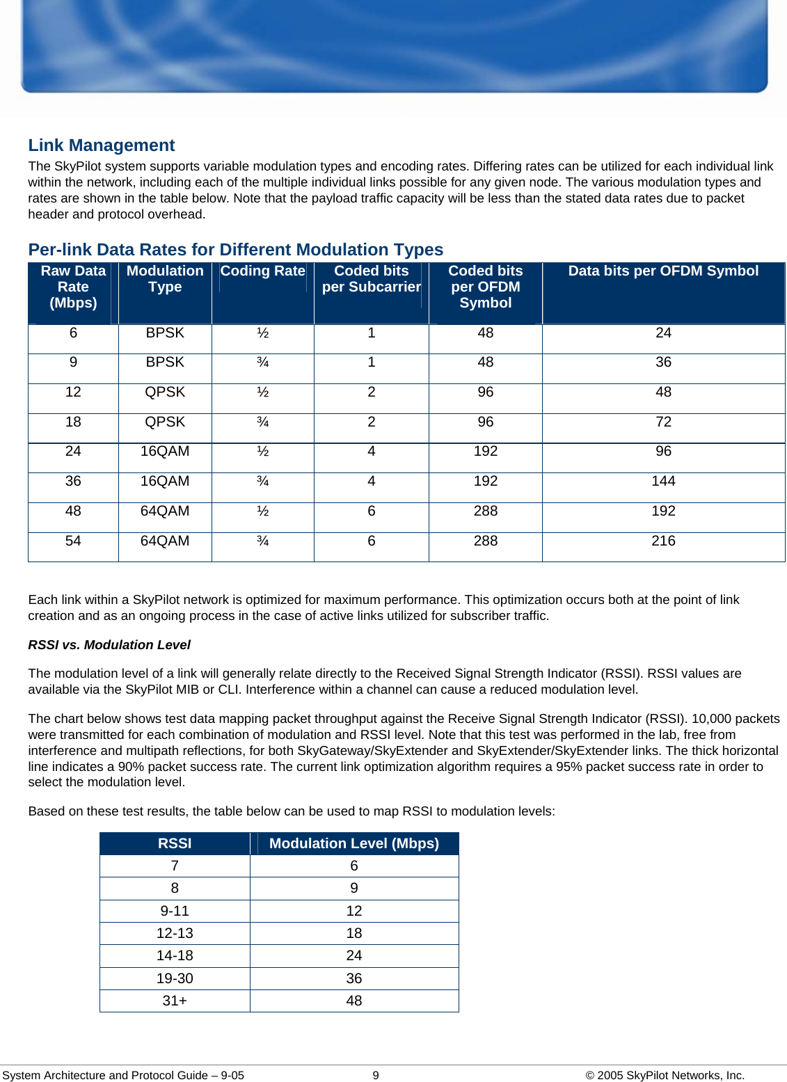
Manual 3
4.
Users Manual 1
5.
Users Manual 2
6.
Users Manual 3
Manual 3
Navigation menu
Upload a User Manual
Namespaces
Wiki Guide
HTML
PDF
Info
Views
User Manual
Discussion / Help
Navigation