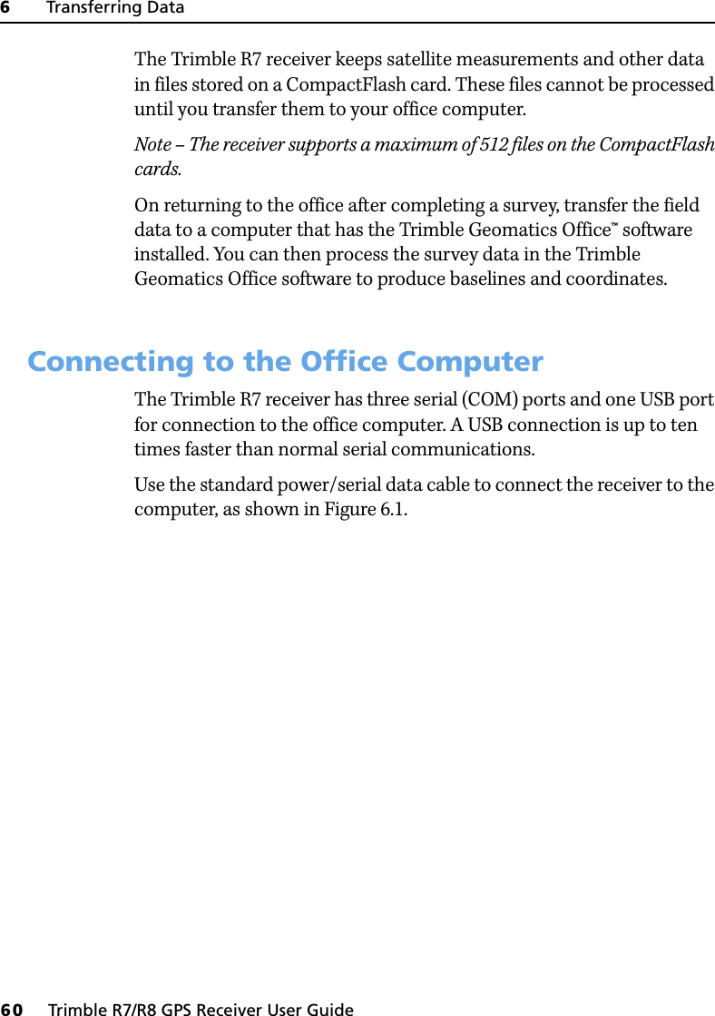
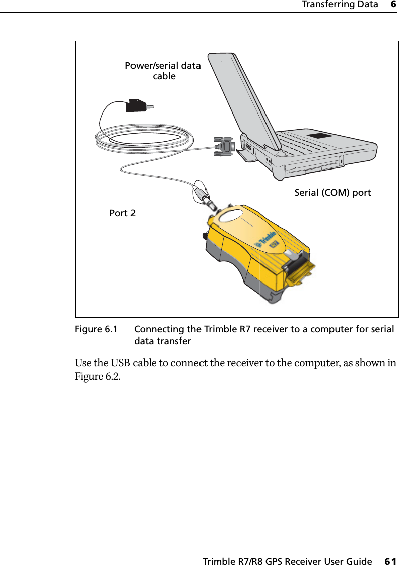
Trimble Navigation TNL450I UHF Radio User Manual Trimble R7 R8 GPS Receiver User Guide
Trimble Navigation Ltd UHF Radio Trimble R7 R8 GPS Receiver User Guide
UserManual.wiki
>
Trimble Navigation
>
TNL450I User Manual
User Manual
Navigation menu
Upload a User Manual
Namespaces
Wiki Guide
HTML
PDF
Info
Views
User Manual
Discussion / Help
Navigation

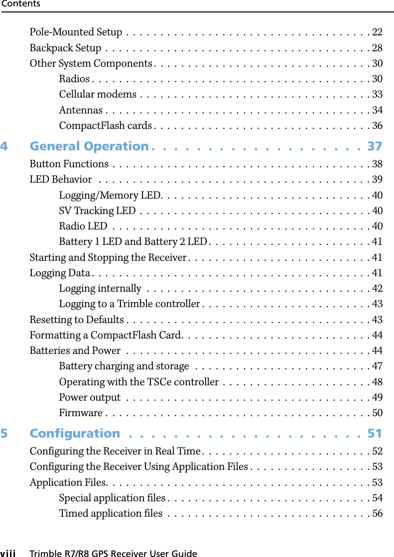


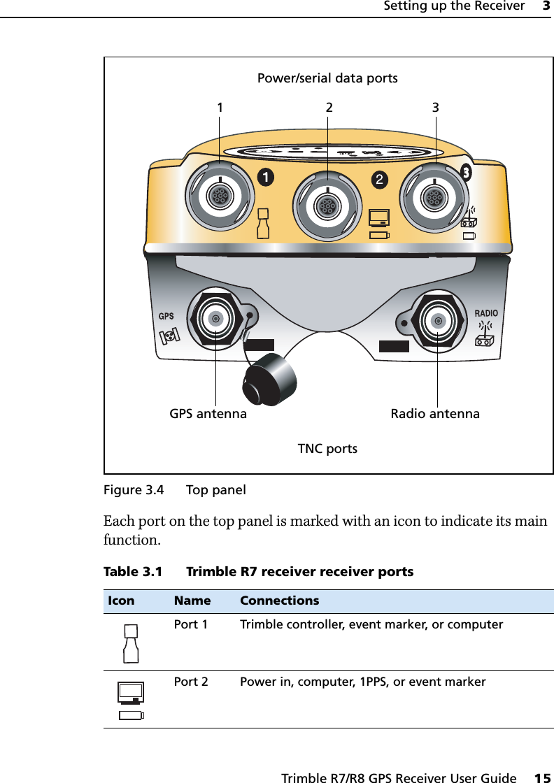
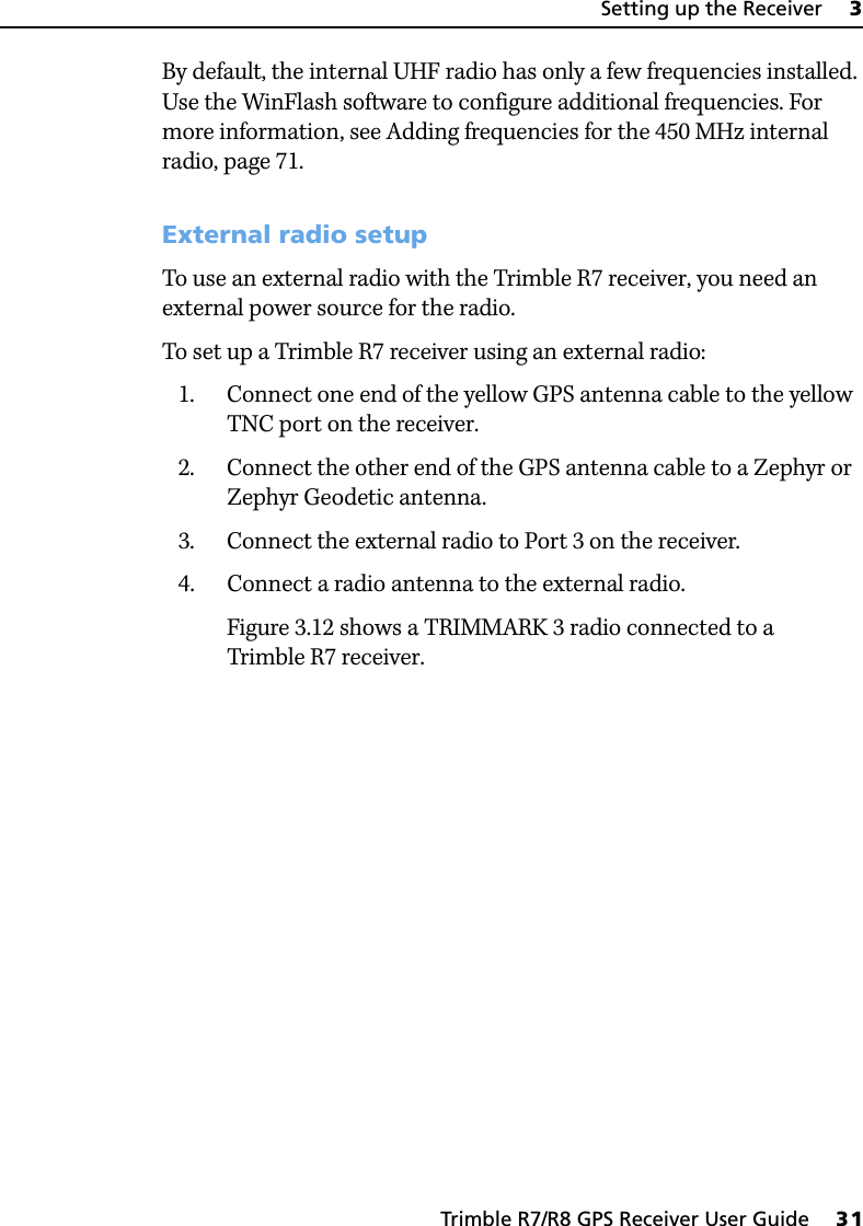
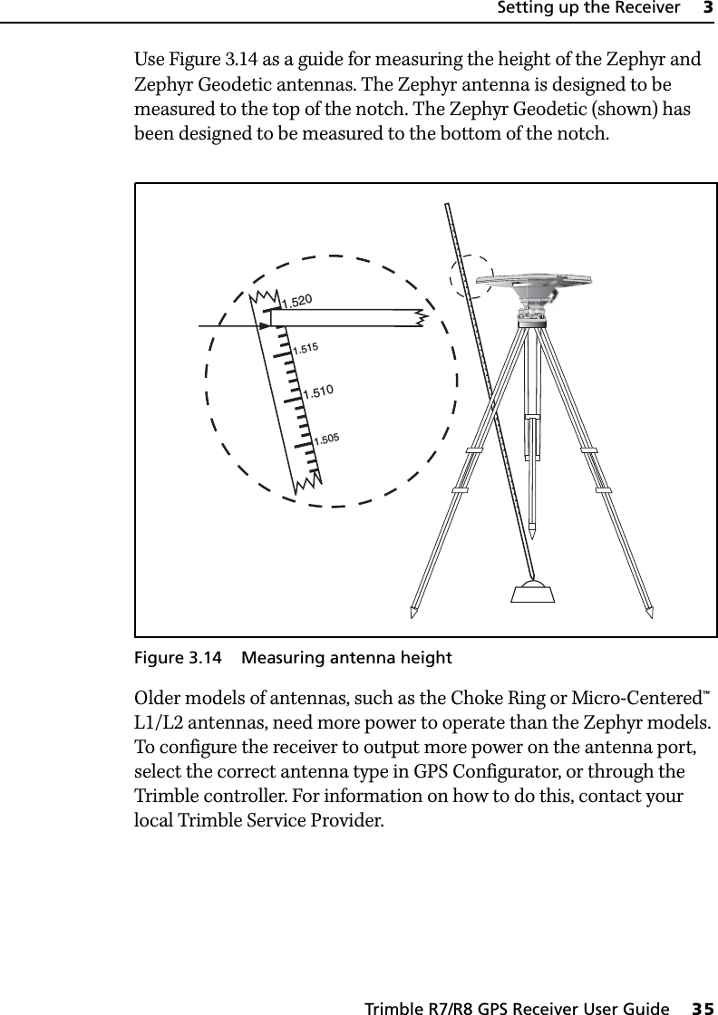
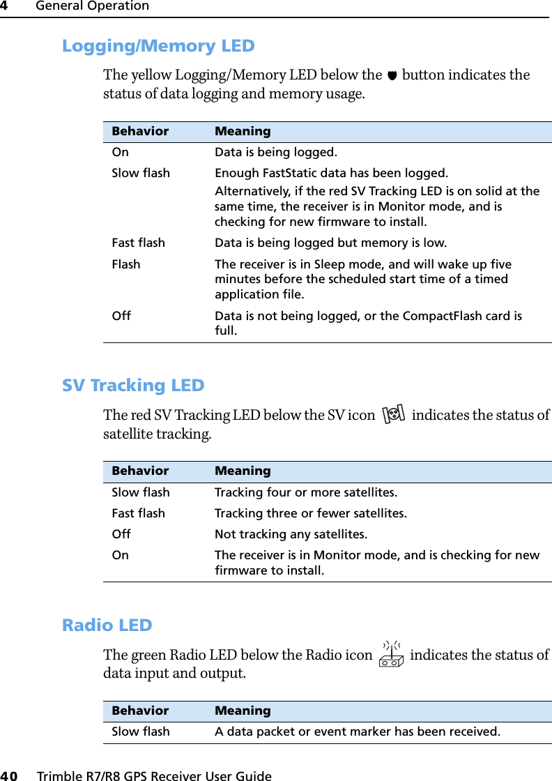
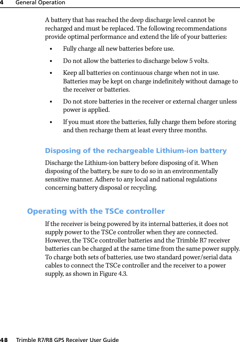
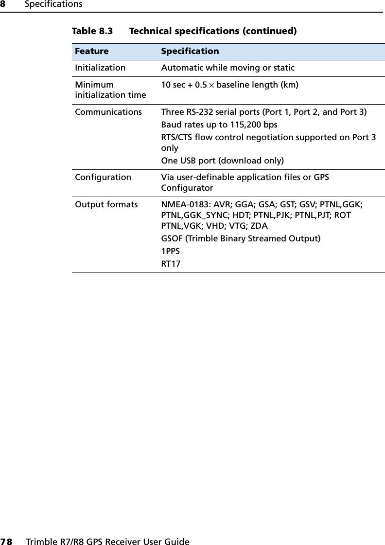
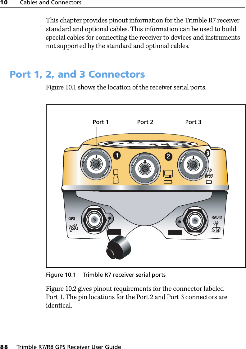
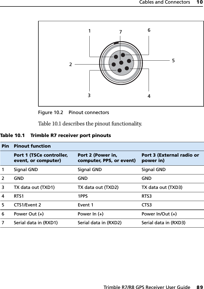
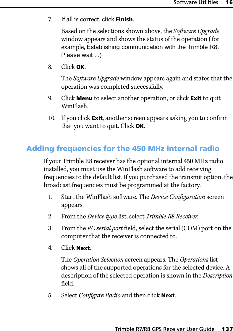
![4 General Operation38 Trimble R7/R8 GPS Receiver User GuideTrimble R7 GPS Receiver Operation All the controls that you need for general operation of the Trimble R7 receiver are located on the front panel, as shown in Figure 4.1.Figure 4.1 Controls on the front panel of the Trimble R7 receiverFor more information about other panels of the Trimble R7 receiver, see Parts of the Receiver, page 12.4.1 Button FunctionsThe Trimble R7 receiver has only two buttons: in this manual, the Power button is represented by [P], and the Data button by [D].Press [P] to switch the receiver on or off, and to perform data management functions such as deleting files or resetting the receiver.Press [D] to start or stop logging. This button is only effective when the receiver is switched on and has completed any power-up and initialization tasks.23tLogging/Memory LEDData button [D] Power button [P]Battery LEDsSV TrackingRadio/EventLEDMarker LED](https://usermanual.wiki/Trimble-Navigation/TNL450I/User-Guide-713384-Page-50.png)
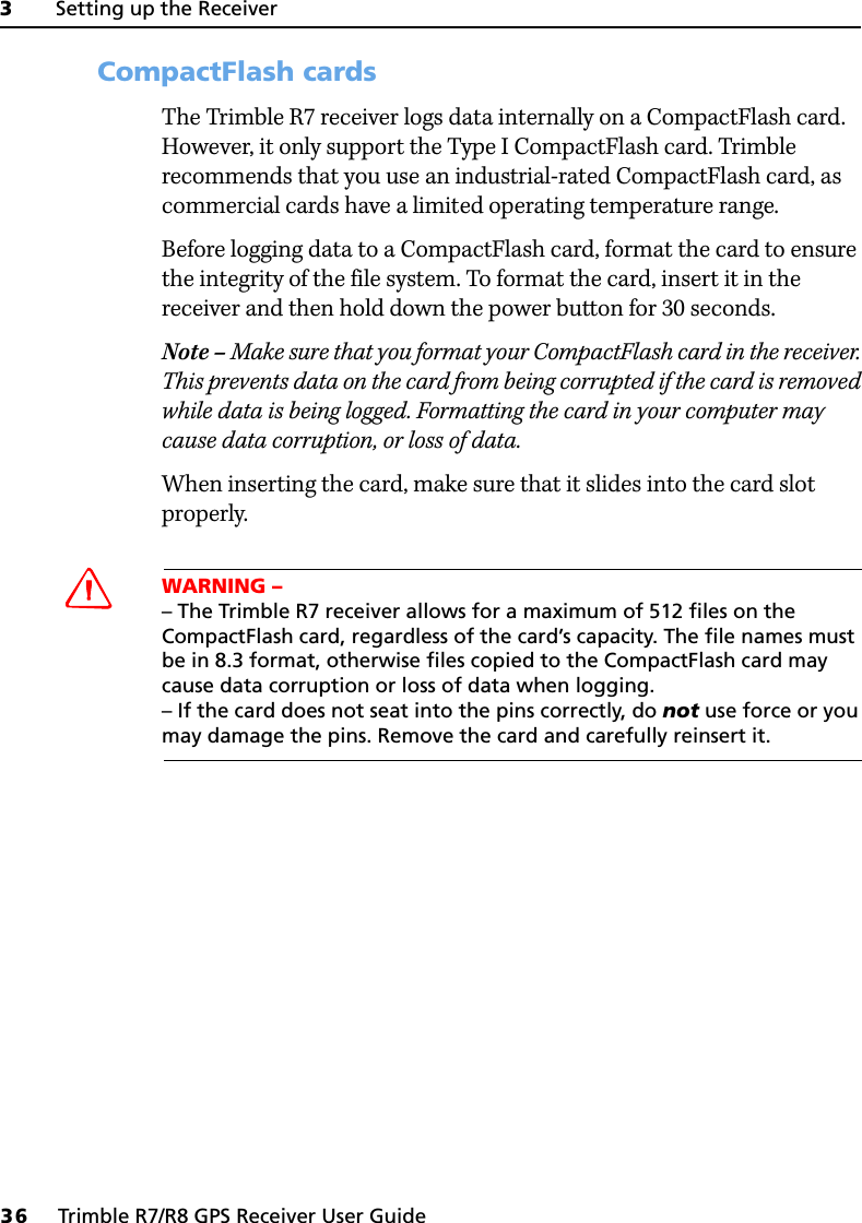
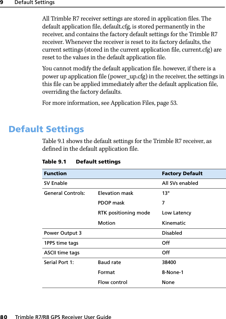
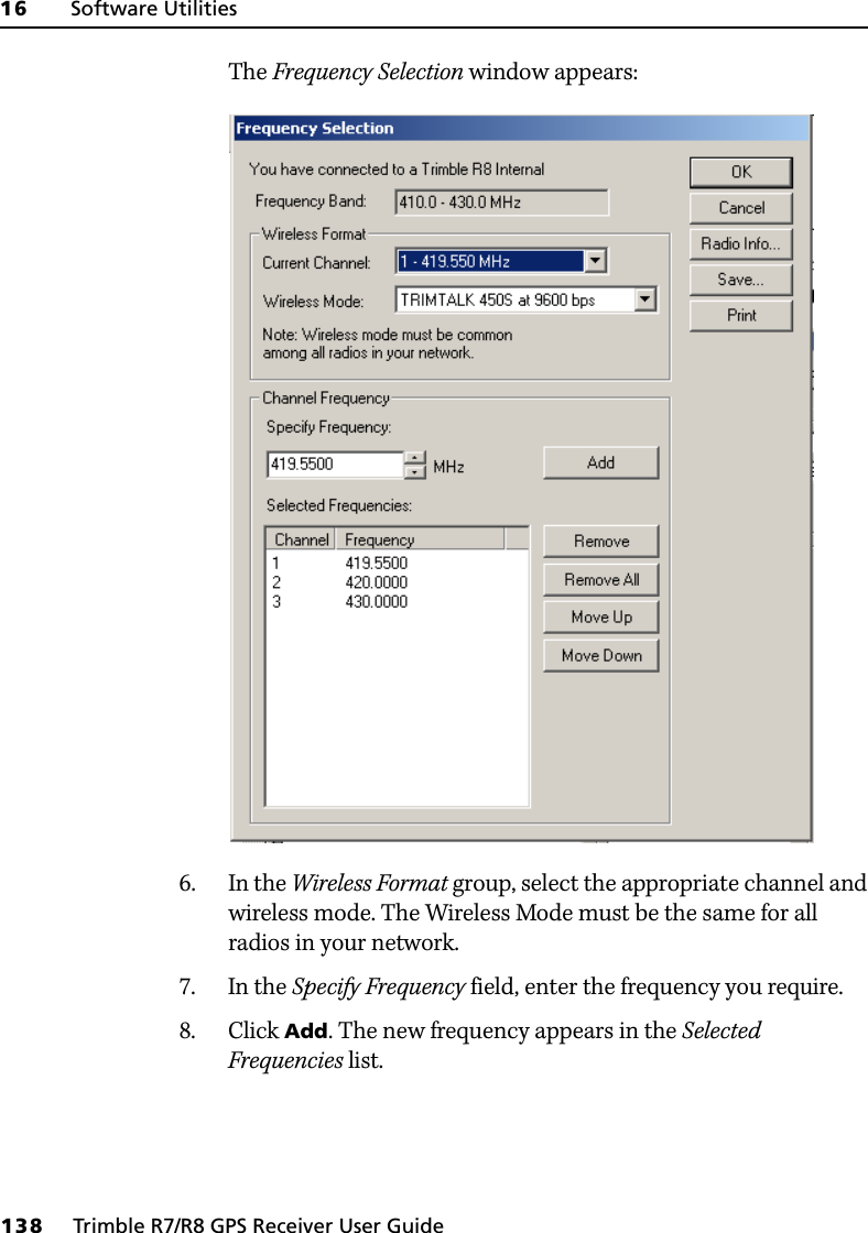
![Trimble R7/R8 GPS Receiver User Guide 41General Operation 4Trimble R7 GPS Receiver Operation 42.4 Battery 1 LED and Battery 2 LEDThe Battery LEDs inside the two Battery icons indicate the status of the two internal batteries, or the power sources connected on Ports 2 and 3. By default, each battery LED indicates the status of the external power source on the corresponding port. If no external source is detected, each LED indicates the status of an internal battery. The color of the LED indicates whether the power source is currently in use (green) or is on standby (yellow). 4.3 Starting and Stopping the ReceiverTo turn on the receiver, press [P].To turn off the receiver, hold down [P] for two seconds.4.4 Logging DataYou can log data to the CompactFlash card in the receiver, or to the survey device.Color Meaning Behavior MeaningGreen Power source is in useOn HealthyFast flash Low powerOff No power source is presentYellow Power source is on standbyOn HealthyFast flash Low powerFlash DeadOff No power source is present](https://usermanual.wiki/Trimble-Navigation/TNL450I/User-Guide-713384-Page-53.png)
![4 General Operation42 Trimble R7/R8 GPS Receiver User GuideTrimble R7 GPS Receiver Operation 44.1 Logging internallyThe Trimble R7 receiver logs GPS data internally on a CompactFlash card. You can then use the Trimble Data Transfer utility to transfer logged data files to your office computer. The transferred files are in Trimble DAT (.dat) format. CWARNING – The Trimble R7 receiver allows for a maximum of 512 files on the CompactFlash card, regardless of the card’s capacity. The file names must be in 8.3 format, otherwise files copied to the CompactFlash card may cause data corruption or loss of data when logging.Data is logged using the current logging settings configured in the receiver. Data files logged internally are named automatically. To begin internal logging, press [D]. The Logging/Memory LED lights up.To stop logging, hold down [D] for at least two seconds. The Logging/Memory LED turns off.Note – When the CompactFlash card is full, the receiver stops logging data, and the Logging/Memory LED switches off. Existing data files are not overwritten.Approximate storage requirements for different logging rates are shown in Table 4.2. The values shown are for a one-hour logging session with six satellites visible. Table 4.2 Storage requirementsLogging rate Memory required10 Hz 2,588 KB1Hz 335 KB5 seconds 87 KB15 seconds 37 KB](https://usermanual.wiki/Trimble-Navigation/TNL450I/User-Guide-713384-Page-54.png)
![Trimble R7/R8 GPS Receiver User Guide 43General Operation 4Trimble R7 GPS Receiver Operation Note – If power is lost, or the CompactFlash card is removed while logging, the file system is designed so that a maximum of ten seconds of data will be lost, regardless of the logging rate. To ensure that this behavior occurs, use GPS Configurator to perform a quick format of the CompactFlash card before logging data to the card for the first time.44.2 Logging to a Trimble controllerWhen the Trimble R7 receiver is connected to a Trimble controller, you can log GPS data from the receiver to the controller, or to a PC card inserted in the controller. When you use a Trimble controller, you do not use the receiver’s controls. Instead, you use the controller functions to set logging options, specify filenames, and to control when logging occurs.Data is stored in job files, which can be transferred to your office computer using Trimble’s Data Transfer utility.For more information on logging data from a receiver using a Trimble controller refer, to the user guide for your particular controller.4.5 Resetting to DefaultsCWARNING – Do not hold down [P] for more than 30 seconds. After 30 seconds, any application files stored in the receiver are deleted and the CompactFlash card is reformatted.To reset the receiver to its factory default settings, hold down [P] for at least 15 seconds.Resetting the receiver to its factory defaults also deletes any ephemeris file in the receiver.For more information, see Chapter 9, Default Settings.](https://usermanual.wiki/Trimble-Navigation/TNL450I/User-Guide-713384-Page-55.png)
![4 General Operation44 Trimble R7/R8 GPS Receiver User GuideTrimble R7 GPS Receiver Operation 4.6 Formatting a CompactFlash CardCWARNING – Formatting a CompactFlash card while it is in the receiver deletes all the data files on the card and all the application files in the receiver.To format a CompactFlash card for use in a Trimble R7 receiver, insert the card in the CompactFlash port and then hold down [P] for at least 30 seconds. After 15 seconds, the receiver is reset to its factory defaults, and any ephemeris file is deleted. After 30 seconds, any files stored on the card are deleted and the CompactFlash card is reformatted.Note – When you use [P] to format the CompactFlash card, a quick format is performed. A quick format reformats the card for use with the Trimble R7 receiver receiver and deletes all data on the card. A full format checks the card for errors or bad sectors, and is only necessary if the card is corrupted. To perform a full format, use the GPS Configurator software. For more information, see The GPS Configurator Software, page 68.4.7 Batteries and PowerCWARNING – Do not damage the rechargeable Lithium-ion battery. A damaged battery can cause an explosion or fire, and can result in personal injury and/or property damage. To prevent injury or damage: – Do not use or charge the battery if it appears to be damaged. Signs of damage include, but are not limited to, discoloration, warping, and leaking battery fluid.– Do not expose the battery to fire, high temperature, or direct sunlight. – Do not immerse the battery in water. – Do not use or store the battery inside a vehicle during hot weather. – Do not drop or puncture the battery. – Do not open the battery or short-circuit its contacts.The Trimble R7 receiver can be powered either by its two internal batteries or by an external power source connected to Port 2 or Port 3. The charge provided by the internal batteries depends on the type of](https://usermanual.wiki/Trimble-Navigation/TNL450I/User-Guide-713384-Page-56.png)
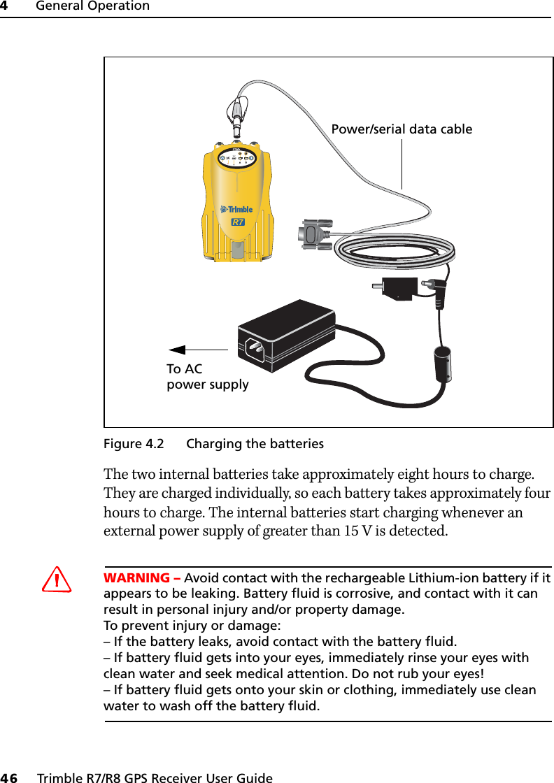
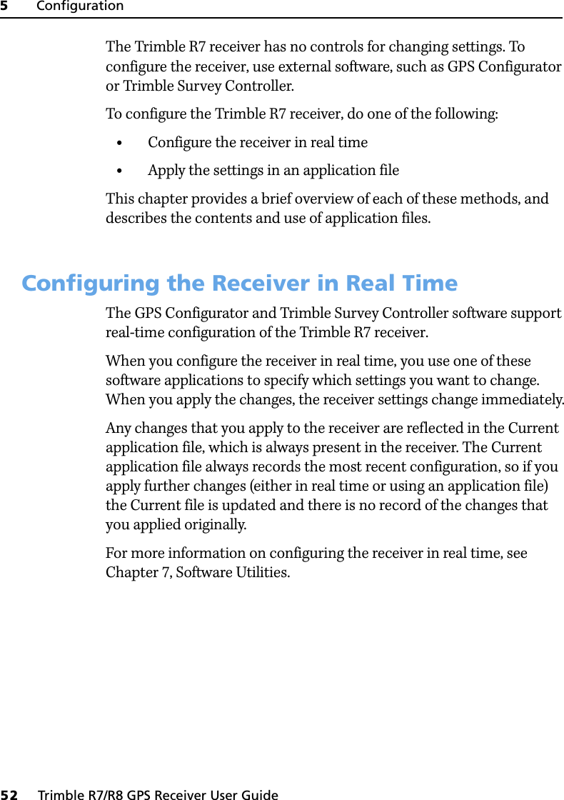
![4 General Operation50 Trimble R7/R8 GPS Receiver User GuideTrimble R7 GPS Receiver Operation On Port 3, the output voltage is approximately 0.5 V less than the input voltage. For example, if power is being supplied from the internal Lithium-ion batteries, the maximum battery voltage is 8.4 V, so the maximum output voltage is 7.9 V.Note – When you start a survey using the Trimble Survey Controller software, and you are using an external radio, the software automatically enables power output on Port 3.47.4 FirmwareA receiver’s firmware is the program inside the receiver that makes the receiver run and controls the hardware. When you need to upgrade the firmware for your Trimble R7 receiver, Trimble recommends that you use the WinFlash software. For more information, see The WinFlash Software, page 69.CWARNING – Upgrading the firmware deletes all application files on the Trimble R7 receiver.An alternative method of upgrading your firmware is to copy the .elf file directly to the CompactFlash card from your computer:1. Connect the CompactFlash card to your desktop computer.2. Using Windows Explorer, copy the .elf file from your computer to the CompactFlash card.3. Disconnect the CompactFlash card from your computer and insert it into the receiver.4. Turn the receiver off.5. Hold down [D] and press [P].The receiver starts up in Monitor mode, automatically detects the newer version of the firmware, and installs it. In Monitor mode, the red SV Tracking LED is lit solidly and the yellow Logging/Memory LED flashes slowly.The upgrade takes about two minutes. Once the upgrade procedure is complete, the receiver restarts automatically.](https://usermanual.wiki/Trimble-Navigation/TNL450I/User-Guide-713384-Page-62.png)

![5 Configuration54 Trimble R7/R8 GPS Receiver User GuideTrimble R7 GPS Receiver Operation An application file does not have to contain all of these records. When you apply an application file, any option that is not included in the records in the file remains at its current setting. For example, if you apply an application file that only specifies the elevation mask to use, all other settings remain as they were before the application file was applied.You can store up to twenty different application files in battery-backed memory on the receiver. You can apply an application file’s settings at the time it is transferred to the receiver, or at any time afterwards.53.1 Special application filesThe Trimble R7 receiver has three special application files, which control important aspects of the receiver’s configuration.Default application fileThe default application file (Default.cfg) contains the original receiver configuration, and cannot be changed. This file configures the receiver after it is reset. To reset the receiver, hold down [P] for at least 15 seconds, or use the reset option in the GPS Configurator software.For more information, see Default Settings, page 80.Although you cannot change or delete the default application file, you can use a power up application file to override any or all of the default settings.Current application fileThe current application file (Current.cfg) reflects the current receiver configuration. Whenever you change the receiver’s configuration, either in real time or by applying an application file, the current file changes to match the new configuration.You cannot delete the current file or change it directly, but every change to the receiver’s current configuration is applied to the current file as well.](https://usermanual.wiki/Trimble-Navigation/TNL450I/User-Guide-713384-Page-66.png)
![Trimble R7/R8 GPS Receiver User Guide 57Configuration 5Trimble R7 GPS Receiver Operation When you apply the current settings in the GPS Configurator software, each defined survey session is sent to the Trimble R7 receiver as a pair of timed application files: the first includes the logging settings and start time, and the second contains settings that stop logging at the end time (which is calculated automatically from the duration you specify).For more information on scheduled survey sessions, refer to the GPS Configurator Help.The receiver can store up to 20 application files, so you can define a maximum of 10 scheduled survey sessions (10 pairs of start/stop timed application files).Sleep modeWhenever you press [P] to turn off the Trimble R7 receiver, the receiver checks for a timed application file that is due to be activated in the future. If one exists, the receiver goes into Sleep mode instead of turning off.In Sleep mode, the yellow Logging/Memory LED flashes every three seconds. The receiver wakes up five minutes before the scheduled activation time, so that it is ready to begin logging at the scheduled time.53.3 Applying application filesAn application file’s settings do not affect the receiver’s configuration until you apply the application file. You can do this at the same time that you save the file. Alternatively, save the file on the computer or in the receiver, then open it later and apply its settings.Note – If the application file is a timed file, its settings do not take effect as soon as you apply the file, but at the time that the file specifies for its activation.](https://usermanual.wiki/Trimble-Navigation/TNL450I/User-Guide-713384-Page-69.png)
![Trimble R7/R8 GPS Receiver User Guide 65Transferring Data 6Trimble R7 GPS Receiver Operation 6.1 Deleting Files in the ReceiverYou can delete files stored in the receiver at any time. Do one of the following:• Use the Data Transfer utility in the Trimble Geomatics Office software.• Use the TSCe controller.• Turn on the receiver and then hold down [P] for 30 seconds. When you use this method, all data is deleted, and the CompactFlash card is reformatted.• Use the GPS Configurator software.6.2 Supported File TypesTable 6.1 shows the file types that you can transfer to or from a Trimble R7 receiver, and the software or utility that you must use to transfer each file type.Note – The Trimble R7 receiver supports a maximum of 512 files on the CompactFlash card. Files stored on the compact flash must be 8.3 format. The Trimble R7 receiver does not support extended file names.Table 6.1 Supported file typesFile Type Extensions Transfer from Trimble R7 receiver?Transfer to Trimble R7 receiver?SoftwareEphemeris .eph Yes No Data TransferRaw observations .T01, .dat Yes No Data TransferReceiver firmware files .elf No Yes WinFlashApplication files .cfg Yes Yes GPS Configurator](https://usermanual.wiki/Trimble-Navigation/TNL450I/User-Guide-713384-Page-77.png)


![Trimble R7/R8 GPS Receiver User Guide 81Default Settings 9Trimble R7 GPS Receiver Operation Serial Port 2: Baud rate 38400Format 8-None-1Serial Port 3: Baud rate 38400Format 8-None-1Flow control NoneInput Setup: Station AnyNMEA/ASCII (all messages) All Ports OffStreamed output All Types OffOffset = 00RT17/Binary All Ports OffCMR output [Static] CMR: cref ID 0000RTCM output RTCM: Type 1 ID 0000Reference position: Latitude 0°Longitude 0°Altitude 0.00 m HAEAntenna: Type Unknown externalHeight (true vertical) 0.00 mGroup AllMeasurement method Bottom of antenna mount Logging rate 15 secPosition rate 5 minMeasurement rate 10 HzTable 9.1 Default settings (continued)Function Factory Default](https://usermanual.wiki/Trimble-Navigation/TNL450I/User-Guide-713384-Page-93.png)
![9 Default Settings82 Trimble R7/R8 GPS Receiver User GuideTrimble R7 GPS Receiver Operation 9.2 Resetting to Factory DefaultsTo reset the receiver to its factory defaults, do one of the following:•On the receiver, press and hold down [P] for 15 seconds.•In the GPS Configurator software, select Connect to Receiver and then click Reset receiver in the General tab.9.3 ExamplesThe following examples show how the Trimble R7 receiver uses the default settings and special application files in various situations.93.1 Default behaviorThe factory defaults are applied whenever you start the receiver. If a Power Up file is present in the receiver, its settings are applied immediately after the default settings, so you can use a Power Up file to define your own set of defaults.When you turn the receiver on and …then logging settings are …and logging …it is the first time that the receiver has been usedthe factory defaults does not begin automaticallyyou have reset the receiver to its factory defaultsthe factory defaults, or those in the Power Up fileaaA factory default setting is only used if the setting is not defined in the Power Up file.does not begin automaticallyyou have performed a full reset the factory defaults, because resetting deletes any Power Up filedoes not begin automatically](https://usermanual.wiki/Trimble-Navigation/TNL450I/User-Guide-713384-Page-94.png)
![Trimble R7/R8 GPS Receiver User Guide 83Default Settings 9Trimble R7 GPS Receiver Operation 93.2 Power up settingsWhen you turn the receiver off, any changes that you have made to logging settings are lost and these settings are returned to the factory defaults. Other settings remain as defined in the Current file. The next time you turn on the receiver, the receiver checks for a power up file and, if one is present, applies the settings in this file.93.3 Logging after power lossIf the Trimble R7 receiver loses power unexpectedly, when power is restored the receiver tries to return to the state it was in immediately before the power loss. The receiver does not reset itself to defaults or apply any Power Up settings. If the receiver was logging when power was lost unexpectedly, it resumes logging when power is restored.When you use [P] to turn the receiver off then on again and …then logging settings are …and all other settings are …you changed the receiver settings by applying an application filethe factory defaults the last settings usedyou changed the receiver settings using configuration softwarethe factory defaults the last settings usedthere is a Power Up application file in the receiverthe factory defaults, or those in the Power Up fileaaA factory default setting is used only if the setting is not defined in the Power Up file.the last settings used, or those in the Power Up filea](https://usermanual.wiki/Trimble-Navigation/TNL450I/User-Guide-713384-Page-95.png)
![9 Default Settings84 Trimble R7/R8 GPS Receiver User GuideTrimble R7 GPS Receiver Operation However, when you turn off the receiver using [P], the receiver behaves as if you pressed [D] to stop logging before you pressed [P]. In this case, when power is restored normally, logging does not begin until you start it manually.93.4 Disabling loggingTo disable logging, you can set the receiver’s data logging and position logging rates to Off. However, if you press [D] while logging is disabled, the receiver will still log data, using the default logging settings.93.5 Application filesYou can use application files to change the settings in the receiver. Sending an application file to the receiver does not necessarily apply the file’s settings; you can apply a file’s settings at any time after sending it to the receiver. You can also define timed application files. A timed application file contains receiver settings, but also includes a date and time when it is automatically activated.If there is a timed application file on the Trimble R7 receiver, the receiver automatically applies the file’s settings and begins logging (if logging settings are included in the file) at the specified time. If the When the receiver is logging data and then loses power …then when power is restored, data logging …and logging settings are …and all other settings are …unexpectedly resumes automaticallythe last settings usedthe last settings usedwhen you press [P] does not resume the factory defaultsthe last settings usedWhen you have disabled logging … then if you press [D] to start logging, logging settings are …using the Trimble Survey Controller or GPS Configurator softwarethe factory defaultsin the Power Up application file the factory defaults](https://usermanual.wiki/Trimble-Navigation/TNL450I/User-Guide-713384-Page-96.png)


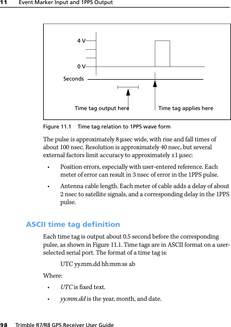
![11 Event Marker Input and 1PPS Output96 Trimble R7/R8 GPS Receiver User GuideTrimble R7 GPS Receiver Operation The Trimble R7 receiver can accept event marker input on Port 1 and Port 2, and can generate 1PPS output on Port 2.11.1Event Marker InputEvent marker input is used to log a precise GPS time tag whenever an externally generated pulse, such as one generated at the time of the shutter closing from a photogrammetric camera, is received. The event is triggered when the source pulse voltage transitions between 1.0 V DC and 2.0 V DC in less than 100 nsec. Trimble recommends that you use TTL level inputs. You can configure the receiver to recognize either a positive (rising) or negative ( falling) voltage as the leading edge of a pulse. The accuracy of the associated time tag recorded for an event is determined by the GPS accuracy (typically less than 1 µsec.).The Trimble R7 receiver records each event in the current data file. This record includes the port on which the event was received.111.1 Enabling and configuring event marker inputTo enable or configure the event marker input function, you need the GPS Configurator software.In real timeYou can use the GPS Configurator software to configure a Trimble GPS receiver connected to your office computer. For more information, see The GPS Configurator Software, page 68, or refer to the GPS Configurator Help.To enable event marker input:1. Connect the computer to the Trimble R7 receiver.2. Press [P] to turn on the receiver.](https://usermanual.wiki/Trimble-Navigation/TNL450I/User-Guide-713384-Page-108.png)


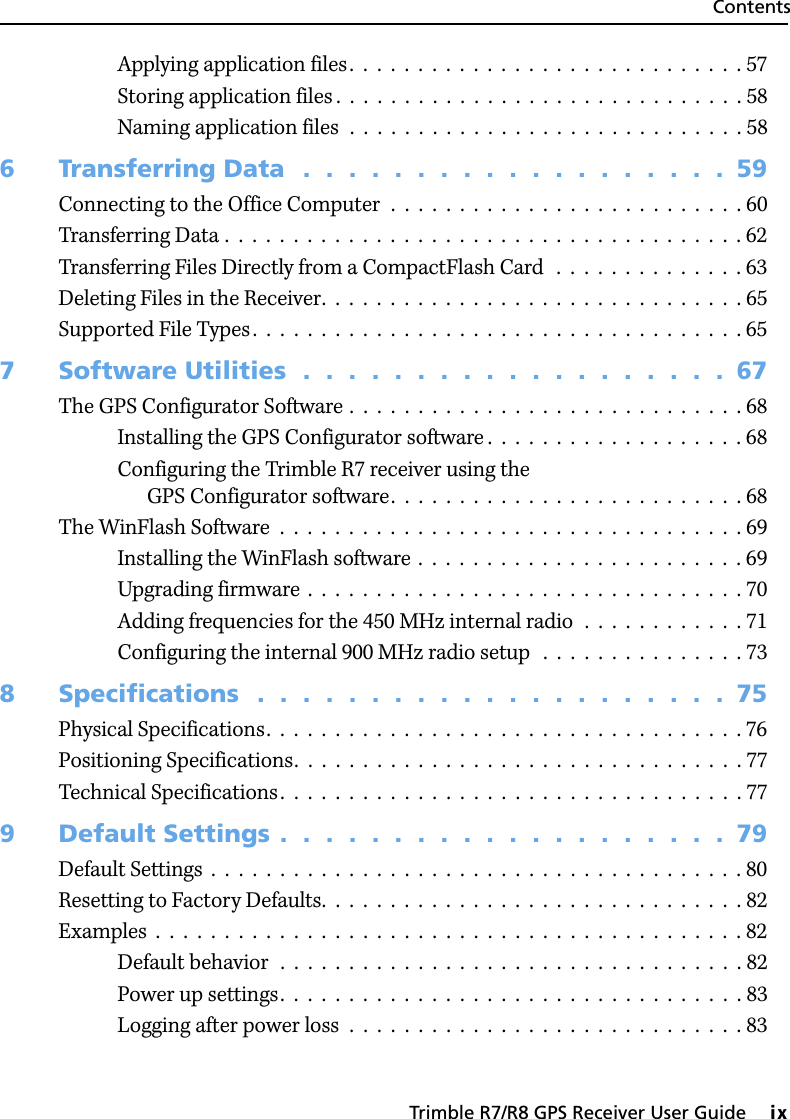
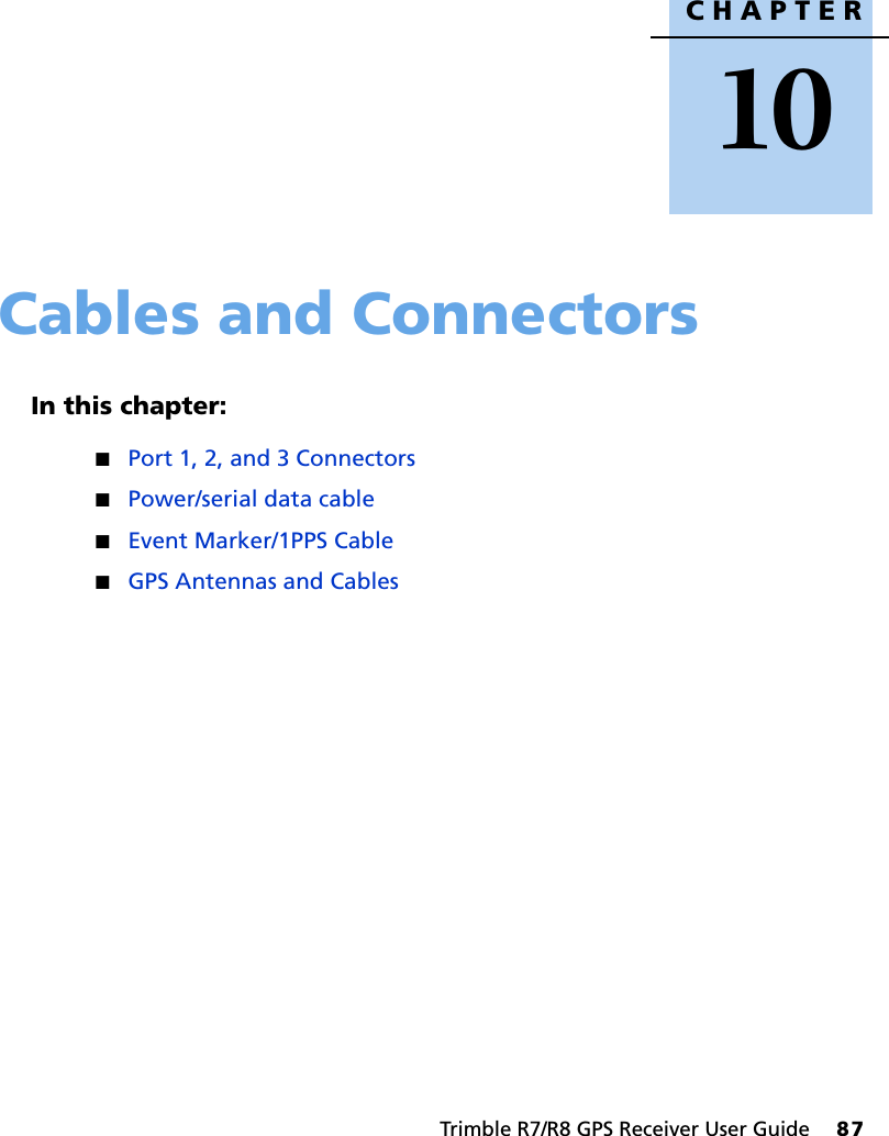
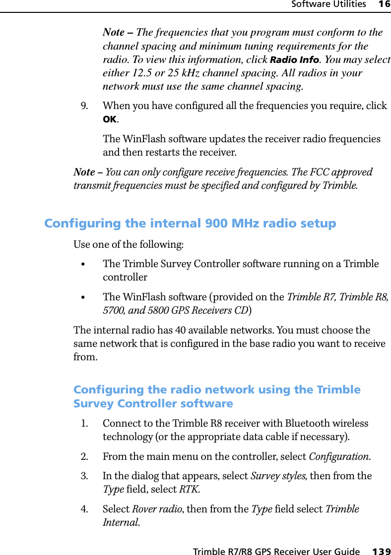
![14 General Operation118 Trimble R7/R8 GPS Receiver User GuideTrimble R8 GPS Receiver Operation Figure 14.1 shows the Trimble R8 receiver front panel controls for the power on/off functions, or receiver reset. The LEDs provide power, radio, data logging, and SV tracking status information.Figure 14.1 Controls and LEDs on front panel of the Trimble R8 receiver14.1Button FunctionsThe Trimble R8 receiver has only one button, the Power button, represented in this manual by [P]. Use [P] to turn on or turn off the receiver, and to perform other functions, as described in Table 14.1.Note – The term “press” means to press the button and release it immediately. The term “hold” means to press the button and hold it down for the given time.Table 14.1 Power button functionsAction Power buttonTurn on the receiver PressTurn off the receiver Hold for 2 secondsDelete the ephemeris file Hold for 15 secondsReset the receiver to factory defaults Hold for 15 secondsDelete application files Hold for 30 secondsFPower buttonSV TrackingRadioPower/Data statusLEDs](https://usermanual.wiki/Trimble-Navigation/TNL450I/User-Guide-713384-Page-130.png)
![14 General Operation120 Trimble R7/R8 GPS Receiver User GuideTrimble R8 GPS Receiver Operation Note – If a column shows “N/A”, that specific LED may or may not be on, but it is not relevant to that particular mode.14.3Starting and Stopping the ReceiverTo turn on the receiver, press [P].To turn off the receiver, hold down [P] for two seconds.14.4Logging DataYou can log data internally or to a Trimble controller.144.1 Logging internallyThe Trimble R8 receiver logs GPS data internally on 6 MB of internal memory.You can then use the Trimble Data Transfer utility to transfer logged data files to the office computer. The transferred files are in Trimble DAT (.dat) format. CWARNING – The Trimble R8 receiver allows for a maximum of 200 files on the internal memory. The filenames must be in 8.3 format, otherwise files copied to the internal memory may cause data corruption or loss of data when logging.Data is logged using the current logging settings configured in the receiver. Data files logged internally are named automatically. No data packets ON OFF N/AReceiver in Monitor ON Slow flash ONReceiver mode Power LEDGreenRadio LEDGreenSatellite LEDAmber](https://usermanual.wiki/Trimble-Navigation/TNL450I/User-Guide-713384-Page-132.png)
![14 General Operation122 Trimble R7/R8 GPS Receiver User GuideTrimble R8 GPS Receiver Operation 14.5Resetting to DefaultsTo reset the receiver to its factory default settings, hold down [P] for at least 15 seconds.For more information, see Default Settings, page 152.14.6Batteries and PowerCWARNING – Do not damage the rechargeable Lithium-ion battery. A damaged battery can cause an explosion or fire, and can result in personal injury and/or property damage. To prevent injury or damage: – Do not use or charge the battery if it appears to be damaged. Signs of damage include, but are not limited to, discoloration, warping, and leaking battery fluid.– Do not expose the battery to fire, high temperature, or direct sunlight. – Do not immerse the battery in water. – Do not use or store the battery inside a vehicle during hot weather. – Do not drop or puncture the battery. – Do not open the battery or short-circuit its contacts.The Trimble R8 receiver can be powered by its internal battery or by an external power source connected to Port 1. Typically, one internal 2.0 ampere-hour battery provides approximately 5.5 hours of operation during an RTK survey using the internal radio in rover mode and approximately 3.5 hours of operation as an RTK base (this varies according to temperature and wireless data rate).If an external power source is connected to Port 1 it is used in preference to the internal battery. When there is no external power source connected, or if the external power supply fails, the internal battery is used. WARNING – Avoid contact with the rechargeable Lithium-ion battery if it appears to be leaking. Battery fluid is corrosive, and contact with it can result in personal injury and/or property damage.To prevent injury or damage:– If the battery leaks, avoid contact with the battery fluid.](https://usermanual.wiki/Trimble-Navigation/TNL450I/User-Guide-713384-Page-134.png)
![15 Configuration130 Trimble R7/R8 GPS Receiver User GuideTrimble R8 GPS Receiver Operation apply an application file that only specifies the elevation mask to use, all other settings remain as they were before the application file was applied.You can store up to twenty different application files in the receiver. You can apply an application file’s settings at the time it is transferred to the receiver, or at any time afterwards.153.1 Special application filesThe Trimble R8 receiver has three special application files, which control important aspects of the receiver’s configuration.Default application fileThe default application file (Default.cfg) contains the original receiver configuration, and cannot be changed. This file configures the receiver after it is reset. You can reset the receiver by holding down [P] for at least 15 seconds, or by using the reset option in the GPS Configurator software.For more information, see Default Settings, page 152.Although you cannot change or delete the default application file, you can use a power up application file to override any or all of the default settings.Current application fileThe current application file (Current.cfg) reflects the current receiver configuration. Whenever you change the receiver’s configuration, either in real time or by applying an application file, the current file changes to match the new configuration.You cannot delete the current file or change it directly, but every change to the receiver’s current configuration is applied to the current file as well.](https://usermanual.wiki/Trimble-Navigation/TNL450I/User-Guide-713384-Page-142.png)


![Trimble R7/R8 GPS Receiver User Guide 153Default Settings 18Trimble R8 GPS Receiver Operation 18.2Resetting to Factory DefaultsTo reset the Trimble R8 receiver to its factory defaults, do one of the following:•On the receiver, press and hold down [P] for 15 seconds.•In the GPS Configurator software, select Connect to Receiver and then click Reset receiver in the General tab.182.1 Default behaviorThe factory defaults specified above are applied whenever you start the receiver. If a power up file is present in the receiver, its settings are applied immediately after the default settings, so you can use a power up file to define your own set of defaults.Input Setup: Station AnyNMEA/ASCII (all messages) All Ports OffStreamed output All Types OffOffset = 00RT17/Binary All Ports OffReference position: Latitude 0°Longitude 0°Altitude 0.00 m HAEAntenna: Type Trimble R8/5800 InternalHeight (true vertical) 0.00 mGroup AllMeasurement method Bottom of mountTable 18.1 Default settings (continued)Function Factory default](https://usermanual.wiki/Trimble-Navigation/TNL450I/User-Guide-713384-Page-165.png)
![18 Default Settings154 Trimble R7/R8 GPS Receiver User GuideTrimble R8 GPS Receiver Operation 182.2 Power up settingsWhen you turn off the receiver, any changes that you have made to logging settings are lost and these settings are returned to the factory defaults. Other settings remain as defined in the current file. The next time you turn on the receiver, the receiver checks for a power up file and, if one is present, applies the settings in this file.When you use [P] to turn off and then turn on the receiver and …then logging settings are …and all other settings are …you changed the receiver settings by applying an application filethe factory defaults the last settings usedyou changed the receiver settings using configuration softwarethe factory defaults the last settings usedthere is a Power Up application file in the receiverthe factory defaults, or those in the Power Up fileaaA factory default setting is used only if the setting is not defined in the Power Up file.the last settings used, or those in the Power Up file](https://usermanual.wiki/Trimble-Navigation/TNL450I/User-Guide-713384-Page-166.png)


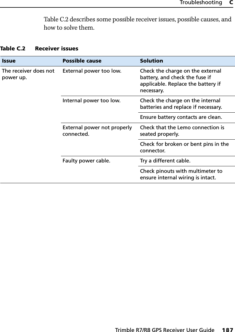
![C Troubleshooting188 Trimble R7/R8 GPS Receiver User GuideTrimbleR7/R8 GPS Receiver Operation Receiver does not log data.Insufficient memory on the CompactFlash card.Delete old files using the GPS Configurator or Trimble Survey Controller software, or by holding down [P] for 30 seconds.No CompactFlash card is inserted.Insert a CompactFlash card in the receiver.The CompactFlash card is not seated properly.Remove the Compact Flash card and reinsert it, making sure that it slides into the housing easily and seats into the pins.The receiver is tracking fewer than four satellites.Wait until the SV Tracking LED is flashing slowly.The CompactFlash card is not formatted, or is corrupted.Format the CompactFlash card using the GPS Configurator software, or by holding down [P] for 30 seconds. If the problem persists, use the GPS Configurator software to perform a full format.The receiver is not responding.Receiver needs soft reset. Power down the receiver and power back up.Receiver needs full reset. Hold down [P] for 30 seconds. If you want to retain data files, remove the CompactFlash card first.Table C.2 Receiver issues (continued)Issue Possible cause Solution](https://usermanual.wiki/Trimble-Navigation/TNL450I/User-Guide-713384-Page-200.png)