Trimble Outdoors Aggps 332 Users Manual GPS Receiver User Guide
AgGPS 332 140721f0-11aa-45e6-ae6f-541de2761d07
332 to the manual 140721f0-11aa-45e6-ae6f-541de2761d07
2015-02-03
: Trimble-Outdoors Trimble-Outdoors-Aggps-332-Users-Manual-460240 trimble-outdoors-aggps-332-users-manual-460240 trimble-outdoors pdf
Open the PDF directly: View PDF ![]() .
.
Page Count: 126 [warning: Documents this large are best viewed by clicking the View PDF Link!]
- USER GUIDE
- Legal Notices
- Contents
- Introduction
- Overview
- Connecting the Receiver
- Introduction
- System Components
- Mounting the Receiver
- Connecting to an External Device
- System Components
- Routing and Connecting the Antenna Cable
- Connecting to the EZ-Guide Plus System
- Connecting to the EZ-Steer Assisted Steering System
- Connecting to a Laptop Computer
- Connecting to a Windows Handheld Computer
- Getting Started
- Configuring the Receiver
- Troubleshooting
- Cables and Connectors
- Specifications
- NMEA-0183 Messages
- Introduction
- NMEA-0183 Message Structure
- NMEA Message Summary
- GGA (GPS Fix Data)
- GLL (Position Data)
- GRS (GPS Range Residuals)
- GSA (GPS DOP and Active Satellites)
- GST (GPS PRN)
- GSV (GPS Satellites in View)
- MSS (Beacon Receiver Signal Status)
- RMC (Recommended Minimum Specific GPS Data)
- VTG (Course Over Ground and Ground Speed)
- XTE (Cross-Track Error)
- ZDA (Time and Date)
- PTNLEV Proprietary (Event Marker)
- PTNLID Proprietary (Trimble Receiver ID)
- PTNLDG Proprietary (Trimble DGPS Receiver Status)
- PTNL,GGK (Time, Position, Position Type, and DOP)
- PTNLSM Proprietary (RTCM Special)
- Third-Party Interface Requirements
- Index

USER GUIDE
AgGPS® 332 GPS Receiver
56370-00_332GPS_reciever_MC_7.25x9_0805.indd 1 15/08/2005 9:28:10 a.m.

www.trimble.com
Trimble Navigation Limited
Agriculture Business Area
7401 Church Ranch Blvd
Westminster, CO 80021
USA
+1-913-495-2700 Phone
Trimble Navigation Limited
Corporate Headquarters
935 Stewart Drive
Sunnyvale, CA 94085,
USA
+1-408-481-8000 Phone
Trimble Navigation Limited
Agriculture Business Area
Water Management Division
5475 Kellenburger Road
Dayton, Ohio, 45424-1099
USA
+1-937-233-8921 Phone
56370-00_332GPS_reciever_MC_7.25x9_0805.indd 2 15/08/2005 9:28:10 a.m.
Version 1.00
Revision A
Part number 56370-00-ENG
September 2005
USER GUIDE
AgGPS® 332 GPS Receiver
Corporate Office
Trimble Navigation Limited
645 North Mary Avenue
PO Box 3642
Sunnyvale, CA 94085
USA
www.trimble.com
Legal Notices
© 2005, Trimble Navigation Limited. All rights
reserved.Trimble, the Globe & Triangle logo, AgGPS,
AutoPilot, and EZ-Guide are trademarks of Trimble
Navigation Limited registered in the US Patent and
Trademark Office and in other countries. EZ-Steer, Zephyr is
a trademark of Trimble Navigation Limited.
Recon is a trademark of Tripod Data Systems Inc., a wholly
owned subsidiary of Trimble Navigation Limited.
Microsoft, Windows, and ActiveSync are either registered
trademarks or trademarks of Microsoft Corporation in the
United States and/or other countries.
All other trademarks are the property of their respective
owners.
Release Notice
This is the September 2005 release (Revision A) of the AgGPS
332 GPS Receiver User Guide, part number 56370-00-ENG. It
applies to version 1.00 of the AgGPS 332 GPS receiver.
Limited Warranty Terms and Conditions
Product Limited Warranty
Subject to the terms and conditions set forth herein, Trimble
Navigation Limited (“Trimble”) warrants that for a period of
(1) year from date of purchase this Trimble product (the
“Product”) will substantially conform to Trimble's publicly
available specifications for the Product and that the
hardware and any storage media components of the Product
will be substantially free from defects in materials and
workmanship.
Product Software
Product software, whether built into hardware circuitry as
firmware, provided as a standalone computer software
product, embedded in flash memory, or stored on magnetic
or other media, is licensed and not sold. If accompanied by a
separate end user license agreement, use of any such
software will be subject to the terms of such end user license
agreement (including any differing limited warranty terms,
exclusions and limitations), which shall control over the
terms and conditions set forth in this limited warranty).
Software Updates
During the limited warranty period you will be entitled to
receive such Fix Updates and Minor Updates to the Product
software that Trimble releases and makes commercially
available and for which it does not charge separately, subject
to the procedures for delivery to purchasers of Trimble
products generally. If you have purchased the Product from
an authorized Trimble distributor rather than from Trimble
directly, Trimble may, at its option, forward the software Fix
Update or Minor Update to the Trimble distributor for final
distribution to you. Major Upgrades, new products, or
substantially new software releases, as identified by Trimble
are expressly excluded from this update process and limited
warranty. Receipt of software updates shall not serve to
extend the limited warranty period.
For purposes of this warranty the following definitions shall
apply: (1) “Fix Update” means an error correction or other
update created to fix a previous software version that does
not substantially conform to its published specifications; (2)
“Minor Update” occurs when enhancements are made to
current features in a software program; and (3) “Major
Upgrade” occurs when significant new features are added to
software, or when a new product containing new features
replaces the further development of a current product line.
Trimble reserves the right to determine, in its sole discretion,
what constitutes a significant new feature and Major
Upgrade.
Warranty Remedies
If the Trimble Product fails during the warranty period for
reasons covered by this Limited Warranty and you notify
Trimble of such failure during the warranty period, Trimble
at its option will repair OR replace the nonconforming
Product, OR refund the purchase price paid by you for the
Product, upon your return of the Product to Trimble in
accordance with Trimble's standard return material
authorization procedures.
How to Obtain Warranty Service
To obtain warranty service for the Product, please contact
your Trimble dealer. Alternatively, you may contact Trimble
to request warranty service at +1-408-481-6940 (24 hours a
day) or e-mail your request to trimble_support@trimble.com.
Please be prepared to provide:
– your name, address, and telephone numbers
– proof of purchase
– this Trimble warranty card
– a description of the nonconforming Product including the
model number
– an explanation of the problem.
The customer service representative may need additional
information from you depending on the nature of the
problem.
Warranty Exclusions and Disclaimer
This Product limited warranty shall only apply in the event
and to the extent that (i) the Product is properly and
correctly installed, configured, interfaced, maintained,
stored, and operated in accordance with Trimble's applicable
operator's manual and specifications, and; (ii) the Product is
not modified or misused. This Product limited warranty shall
not apply to, and Trimble shall not be responsible for defects
or performance problems resulting from (i) the combination
or utilization of the Product with hardware or software
products, information, data, systems, interfaces or devices
not made, supplied or specified by Trimble; (ii) the
operation of the Product under any specification other
than, or in addition to, Trimble's standard specifications for
its products; (iii) the unauthorized, installation, modification,
or use of the Product; (iv) damage caused by: accident,
lightning or other electrical discharge, fresh or salt water
immersion or spray; or exposure to environmental
conditions for which the Product is not intended; or (v)
normal wear and tear on consumable parts (e.g., batteries).
Trimble does not warrant or guarantee the results obtained
through the use of the Product. NOTICE REGARDING
PRODUCTS EQUIPPED WITH GPS TECHNOLOGY:
TRIMBLE IS NOT RESPONSIBLE FOR THE OPERATION OR
FAILURE OF OPERATION OF GPS SATELLITES OR THE
AVAILABILITY OF GPS SATELLITE SIGNALS.

THE FOREGOING LIMITED WARRANTY TERMS STATE
TRIMBLE'S ENTIRE LIABILITY, AND YOUR EXCLUSIVE
REMEDIES, RELATING TO PERFORMANCE OF THE
TRIMBLE PRODUCT. EXCEPT AS OTHERWISE EXPRESSLY
PROVIDED HEREIN, THE PRODUCT AND
ACCOMPANYING DOCUMENTATION AND MATERIALS
ARE PROVIDED “AS-IS” AND WITHOUT EXPRESS OR
IMPLIED WARRANTY OF ANY KIND, BY EITHER TRIMBLE
OR ANYONE WHO HAS BEEN INVOLVED IN ITS
CREATION, PRODUCTION, INSTALLATION, OR
DISTRIBUTION, INCLUDING, BUT NOT LIMITED TO, THE
IMPLIED WARRANTIES OF MERCHANTABILITY AND
FITNESS FOR A PARTICULAR PURPOSE, TITLE, AND
NONINFRINGEMENT. THE STATED EXPRESS
WARRANTIES ARE IN LIEU OF ALL OBLIGATIONS OR
LIABILITIES ON THE PART OF TRIMBLE ARISING OUT OF,
OR IN CONNECTION WITH, ANY PRODUCT.
SOME STATES AND JURISDICTIONS DO NOT ALLOW
LIMITATIONS ON DURATION OR THE EXCLUSION OF AN
IMPLIED WARRANTY, SO THE ABOVE LIMITATION MAY
NOT APPLY TO YOU.
Limitation of Liability
TRIMBLE'S ENTIRE LIABILITY UNDER ANY PROVISION
HEREIN SHALL BE LIMITED TO THE AMOUNT PAID BY
YOU FOR THE PRODUCT. TO THE MAXIMUM EXTENT
PERMITTED BY APPLICABLE LAW, IN NO EVENT SHALL
TRIMBLE OR ITS SUPPLIERS BE LIABLE FOR ANY
INDIRECT, SPECIAL, INCIDENTAL OR CONSEQUENTIAL
DAMAGE WHATSOEVER UNDER ANY CIRCUMSTANCE
OR LEGAL THEORY RELATING IN ANYWAY TO THE
PRODUCTS, SOFTWARE AND ACCOMPANYING
DOCUMENTATION AND MATERIALS, (INCLUDING,
WITHOUT LIMITATION, DAMAGES FOR LOSS OF
BUSINESS PROFITS, BUSINESS INTERRUPTION, LOSS OF
DATA, OR ANY OTHER PECUNIARY LOSS), REGARDLESS
OF WHETHER TRIMBLE HAS BEEN ADVISED OF THE
POSSIBILITY OF ANY SUCH LOSS AND REGARDLESS OF
THE COURSE OF DEALING WHICH DEVELOPS OR HAS
DEVELOPED BETWEEN YOU AND TRIMBLE. BECAUSE
SOME STATES AND JURISDICTIONS DO NOT ALLOW THE
EXCLUSION OR LIMITATION OF LIABILITY FOR
CONSEQUENTIAL OR INCIDENTAL DAMAGES, THE
ABOVE LIMITATION MAY NOT APPLY TO YOU.
PLEASE NOTE: THE ABOVE TRIMBLE LIMITED
WARRANTY PROVISIONS WILL NOT APPLY TO
PRODUCTS PURCHASED IN THOSE
JURISDICTIONS, SUCH AS COUNTRIES OF THE
EUROPEAN ECONOMIC COMMUNITY, IN WHICH
PRODUCT WARRANTIES ARE OBTAINED FROM
THE LOCAL DISTRIBUTOR. IN SUCH CASE, PLEASE
CONTACT YOUR TRIMBLE DEALER FOR
APPLICABLE WARRANTY INFORMATION.
Registration
To receive information regarding updates and new products,
please contact your local dealer or visit the Trimble website
at lwww.trimble.com/register. Upon registration you may
select the newsletter, upgrade or new product information
you desire.
Notices
Class B Statement – Notice to Users. This equipment has
been tested and found to comply with the limits for a Class B
digital device, pursuant to Part 15 of the FCC rules. These
limits are designed to provide reasonable protection against
harmful interference in a residential installation. This
equipment generates, uses, and can radiate radio frequency
energy and, if not installed and used in accordance with the
instructions, may cause harmful interference to radio
communication. However, there is no guarantee that
interference will not occur in a particular installation. If this
equipment does cause harmful interference to radio or
television reception, which can be determined by turning the
equipment off and on, the user is encouraged to try to correct
the interference by one or more of the following measures:
– Reorient or relocate the receiving antenna.
– Increase the separation between the equipment and the
receiver.
– Connect the equipment into an outlet on a circuit
different from that to which the receiver is connected.
– Consult the dealer or an experienced radio/TV technician
for help.
Changes and modifications not expressly approved by the
manufacturer or registrant of this equipment can void your
authority to operate this equipment under Federal
Communications Commission rules.
Canada
This digital apparatus does not exceed the Class B limits for
radio noise emissions from digital apparatus as set out in the
radio interference regulations of the Canadian Department
of Communications.
Le présent appareil numérique n’émet pas de bruits
radioélectriques dépassant les limites applicables aux
appareils numériques de Classe B prescrites dans le
règlement sur le brouillage radioélectrique édicté par le
Ministère des Communications du Canada.
Europe
This product has been tested and found to comply
with the requirements for a Class B device pursuant
to European Council Directive 89/336/EEC on EMC,
thereby satisfying the requirements for CE Marking and sale
within the European Economic Area (EEA). Contains
Infineon radio module ROK 104001. These requirements are
designed to provide reasonable protection against harmful
interference when the equipment is operated in a residential
or commercial environment.
Taiwan – Battery Recycling Requirements
The product contains a removable Lithium-ion
battery. Taiwanese regulations require that waste
batteries are recycled.
Notice to Our European Union Customers
For product recycling instructions and more information,
please go to www.trimble.com/environment/summary.html.
Recycling in Europe: To recycle Trimble WEEE
(Waste Electrical and Electronic Equipment,
products that run on electrical power.), Call +31 497
53 24 30, and ask for the "WEEE Associate". Or, mail
a request for recycling instructions to:
Trimble Europe BV
c/o Menlo Worldwide Logistics
Meerheide 45
5521 DZ Eersel, NL
AgGPS 332 GPS Receiver User Guide v
Contents
1 Introduction . . . . . . . . . . . . . . . . . . . . . . . 1
Welcome . . . . . . . . . . . . . . . . . . . . . . . . . . . . . . . . . . . . . . . . . . . .2
About the Product . . . . . . . . . . . . . . . . . . . . . . . . . . . . . . . . . . . . . .2
Related Information . . . . . . . . . . . . . . . . . . . . . . . . . . . . . . . . . . . . .2
Technical Assistance . . . . . . . . . . . . . . . . . . . . . . . . . . . . . . . . . . . . .2
Your Comments . . . . . . . . . . . . . . . . . . . . . . . . . . . . . . . . . . . . . . . .2
2 Overview . . . . . . . . . . . . . . . . . . . . . . . . . 3
Introduction . . . . . . . . . . . . . . . . . . . . . . . . . . . . . . . . . . . . . . . . . .4
Standard Features . . . . . . . . . . . . . . . . . . . . . . . . . . . . . . . . . .5
Receiver Connections . . . . . . . . . . . . . . . . . . . . . . . . . . . . . . . . . . . .6
Receiver Input/Output. . . . . . . . . . . . . . . . . . . . . . . . . . . . . . . . . . . .7
GPS Positioning Methods . . . . . . . . . . . . . . . . . . . . . . . . . . . . . . . . . .9
RTK GPS positioning . . . . . . . . . . . . . . . . . . . . . . . . . . . . . . . .9
Differential GPS positioning (DGPS). . . . . . . . . . . . . . . . . . . . . . 10
Autonomous GPS positioning . . . . . . . . . . . . . . . . . . . . . . . . . . 11
Sources of Error in GPS Positioning . . . . . . . . . . . . . . . . . . . . . . 12
Coordinate systems . . . . . . . . . . . . . . . . . . . . . . . . . . . . . . . . 14
Satellite DGPS mode status indicators . . . . . . . . . . . . . . . . . . . . 15
Receiver input / output . . . . . . . . . . . . . . . . . . . . . . . . . . . . . . 16
DGPS accuracy . . . . . . . . . . . . . . . . . . . . . . . . . . . . . . . . . . . 16
Receiving Beacon DGPS . . . . . . . . . . . . . . . . . . . . . . . . . . . . . 17
3 Connecting the Receiver . . . . . . . . . . . . . . . 19
Introduction . . . . . . . . . . . . . . . . . . . . . . . . . . . . . . . . . . . . . . . . . 20
System Components . . . . . . . . . . . . . . . . . . . . . . . . . . . . . . . . . . . . 20

Contents
vi AgGPS 332 GPS Receiver User Guide
Optional components . . . . . . . . . . . . . . . . . . . . . . . . . . . . . . . 20
Mounting the Receiver. . . . . . . . . . . . . . . . . . . . . . . . . . . . . . . . . . . 21
Choosing a location . . . . . . . . . . . . . . . . . . . . . . . . . . . . . . . . 21
Environmental conditions . . . . . . . . . . . . . . . . . . . . . . . . . . . . 22
Electrical interference . . . . . . . . . . . . . . . . . . . . . . . . . . . . . . . 22
Connecting to an External Device . . . . . . . . . . . . . . . . . . . . . . . . . . . 23
System Components . . . . . . . . . . . . . . . . . . . . . . . . . . . . . . . . . . . . 25
The receiver . . . . . . . . . . . . . . . . . . . . . . . . . . . . . . . . . . . . . 25
The antenna . . . . . . . . . . . . . . . . . . . . . . . . . . . . . . . . . . . . . 26
Routing and Connecting the Antenna Cable . . . . . . . . . . . . . . . . . . . . . 26
Connecting to the EZ-Guide Plus System . . . . . . . . . . . . . . . . . . . . . . . 29
Connecting to the EZ-Steer Assisted Steering System . . . . . . . . . . . . . . . 30
Connecting to a Laptop Computer . . . . . . . . . . . . . . . . . . . . . . . . . . . 31
Connecting to a Windows Handheld Computer . . . . . . . . . . . . . . . . . . 32
4 Getting Started . . . . . . . . . . . . . . . . . . . . 33
Introduction . . . . . . . . . . . . . . . . . . . . . . . . . . . . . . . . . . . . . . . . . 34
Front Panel . . . . . . . . . . . . . . . . . . . . . . . . . . . . . . . . . . . . . . . . . . 34
Navigating the Menus and Screens . . . . . . . . . . . . . . . . . . . . . . . . . . . 35
Menu System Fields . . . . . . . . . . . . . . . . . . . . . . . . . . . . . . . . . . . . 37
Display-only fields . . . . . . . . . . . . . . . . . . . . . . . . . . . . . . . . . 37
Multiple-choice fields . . . . . . . . . . . . . . . . . . . . . . . . . . . . . . . 37
Text fields. . . . . . . . . . . . . . . . . . . . . . . . . . . . . . . . . . . . . . . 38
The Home Screen . . . . . . . . . . . . . . . . . . . . . . . . . . . . . . . . . . . . . . 39
Satellite DGPS mode. . . . . . . . . . . . . . . . . . . . . . . . . . . . . . . . 39
Satellite and SBAS DGPS mode . . . . . . . . . . . . . . . . . . . . . . . . . 40
Beacon DGPS mode . . . . . . . . . . . . . . . . . . . . . . . . . . . . . . . . 43
Updating the Firmware . . . . . . . . . . . . . . . . . . . . . . . . . . . . . . . . . . 44
5 Configuring the Receiver . . . . . . . . . . . . . . . 45
Introduction . . . . . . . . . . . . . . . . . . . . . . . . . . . . . . . . . . . . . . . . . 46
Home Screen . . . . . . . . . . . . . . . . . . . . . . . . . . . . . . . . . . . . . . . . . 46
Configuring Differential GPS . . . . . . . . . . . . . . . . . . . . . . . . . . . . . . . 47

Contents
AgGPS 332 GPS Receiver User Guide vii
OmniSTAR . . . . . . . . . . . . . . . . . . . . . . . . . . . . . . . . . . . . . . 47
WAAS/EGNOS . . . . . . . . . . . . . . . . . . . . . . . . . . . . . . . . . . . 48
Configuring the AgGPS Receiver to Operate in Beacon Mode . . . . . . . . . . 49
Configuring the AgGPS Receiver to Operate in RTK Mode . . . . . . . . . . . . 50
Configuring the Communication Ports . . . . . . . . . . . . . . . . . . . . . . . . 50
Configuring input/output communication. . . . . . . . . . . . . . . . . . 51
Display Options . . . . . . . . . . . . . . . . . . . . . . . . . . . . . . . . . . . . . . . 54
Installing Passcodes . . . . . . . . . . . . . . . . . . . . . . . . . . . . . . . . . . . . 56
FlashLoader200 utility. . . . . . . . . . . . . . . . . . . . . . . . . . . . . . . 57
6 Troubleshooting . . . . . . . . . . . . . . . . . . . . 59
Introduction . . . . . . . . . . . . . . . . . . . . . . . . . . . . . . . . . . . . . . . . . 60
Problems with GPS . . . . . . . . . . . . . . . . . . . . . . . . . . . . . . . . . . . . . 60
Interference Problems . . . . . . . . . . . . . . . . . . . . . . . . . . . . . . . . . . . 62
Problems with the GPS Receiver . . . . . . . . . . . . . . . . . . . . . . . . . . . . 63
Problems with the FlashLoader200 Utility . . . . . . . . . . . . . . . . . . . . . . 65
A Cables and Connectors . . . . . . . . . . . . . . . . 67
Introduction . . . . . . . . . . . . . . . . . . . . . . . . . . . . . . . . . . . . . . . . . 68
Port A and Port B Connectors . . . . . . . . . . . . . . . . . . . . . . . . . . . . . . 68
Standard Power/Data Cable . . . . . . . . . . . . . . . . . . . . . . . . . . . . . . . 69
B Specifications . . . . . . . . . . . . . . . . . . . . . 71
Introduction . . . . . . . . . . . . . . . . . . . . . . . . . . . . . . . . . . . . . . . . . 72
AgGPS 332 Receiver Physical Characteristics . . . . . . . . . . . . . . . . . . . . 72
GPS Channels Performance . . . . . . . . . . . . . . . . . . . . . . . . . . . . . . . 72
L-Band Satellite Differential Correction Receiver with OmniSTAR Support . 74
Receiver Default Settings . . . . . . . . . . . . . . . . . . . . . . . . . . . . . . . . . 74
DGPS Antenna. . . . . . . . . . . . . . . . . . . . . . . . . . . . . . . . . . . . . . . . 75
Dual-Frequency Antenna . . . . . . . . . . . . . . . . . . . . . . . . . . . . . . . . 75
Beacon Channels . . . . . . . . . . . . . . . . . . . . . . . . . . . . . . . . . . . . . . 75

Contents
viii AgGPS 332 GPS Receiver User Guide
C NMEA-0183 Messages . . . . . . . . . . . . . . . . . 77
Introduction . . . . . . . . . . . . . . . . . . . . . . . . . . . . . . . . . . . . . . . . . 78
NMEA-0183 Message Structure . . . . . . . . . . . . . . . . . . . . . . . . . . . . . 78
Symbols and delimiters . . . . . . . . . . . . . . . . . . . . . . . . . . . . . . 79
Checksum values . . . . . . . . . . . . . . . . . . . . . . . . . . . . . . . . . . 80
Field formats. . . . . . . . . . . . . . . . . . . . . . . . . . . . . . . . . . . . . 80
Null fields. . . . . . . . . . . . . . . . . . . . . . . . . . . . . . . . . . . . . . . 80
Talker ID codes . . . . . . . . . . . . . . . . . . . . . . . . . . . . . . . . . . . 80
Latitude and longitude values . . . . . . . . . . . . . . . . . . . . . . . . . . 81
Time values . . . . . . . . . . . . . . . . . . . . . . . . . . . . . . . . . . . . . 81
Reading NMEA string format . . . . . . . . . . . . . . . . . . . . . . . . . . 81
NMEA Message Summary . . . . . . . . . . . . . . . . . . . . . . . . . . . . . . . . 82
GGA (GPS Fix Data) . . . . . . . . . . . . . . . . . . . . . . . . . . . . . . . . . . . . 84
GLL (Position Data) . . . . . . . . . . . . . . . . . . . . . . . . . . . . . . . . . . . . 85
GRS (GPS Range Residuals). . . . . . . . . . . . . . . . . . . . . . . . . . . . . . . . 86
GSA (GPS DOP and Active Satellites) . . . . . . . . . . . . . . . . . . . . . . . . . 87
GST (GPS PRN) . . . . . . . . . . . . . . . . . . . . . . . . . . . . . . . . . . . . . . . 88
GSV (GPS Satellites in View) . . . . . . . . . . . . . . . . . . . . . . . . . . . . . . . 89
MSS (Beacon Receiver Signal Status). . . . . . . . . . . . . . . . . . . . . . . . . . 90
RMC (Recommended Minimum Specific GPS Data) . . . . . . . . . . . . . . . . 91
VTG (Course Over Ground and Ground Speed) . . . . . . . . . . . . . . . . . . . 93
XTE (Cross-Track Error). . . . . . . . . . . . . . . . . . . . . . . . . . . . . . . . . . 94
ZDA (Time and Date) . . . . . . . . . . . . . . . . . . . . . . . . . . . . . . . . . . . 95
PTNLEV Proprietary (Event Marker). . . . . . . . . . . . . . . . . . . . . . . . . . 96
PTNLID Proprietary (Trimble Receiver ID) . . . . . . . . . . . . . . . . . . . . . . 97
PTNLDG Proprietary (Trimble DGPS Receiver Status) . . . . . . . . . . . . . . 98
PTNL,GGK (Time, Position, Position Type, and DOP) . . . . . . . . . . . . . . 100
PTNLSM Proprietary (RTCM Special) . . . . . . . . . . . . . . . . . . . . . . . . 101
D Third-Party Interface Requirements . . . . . . . . 103
Software . . . . . . . . . . . . . . . . . . . . . . . . . . . . . . . . . . . . . . . . . . . 104
Hardware . . . . . . . . . . . . . . . . . . . . . . . . . . . . . . . . . . . . . . . . . . 105
Index . . . . . . . . . . . . . . . . . . . . . . . . . 109


1 Introduction
2 AgGPS 332 GPS Receiver User Guide
1.1 Welcome
This manual describes how to install and configure the Trimble®
AgGPS® 332 receiver.
Even if you have used other Global Positioning System (GPS) products
before, Trimble recommends that you spend some time reading this
manual to learn about the special features of this product. If you are not
familiar with GPS, visit the Trimble website (www.trimble.com) for an
interactive look at Trimble and GPS.
1.2 About the Product
The AgGPS 332 receiver is an innovative GPS receiver that provides “the
ultimate choice” for Agricultural GPS positioning. Scalable accuracy
levels allow the option of SBAS (Satellite Based Augmentation System),
Beacon, OmniSTAR-VBS/XP/HP, and RTK (Real-Time Kinematic). The
AgGPS 332 can provide the level of accuracy needed for any operation.
1.3 Related Information
Sources of related information include the following:
•Release notes – the release notes describe new features of the
product, information not included in the manuals, and any
changes to the manuals.
•Trimble training courses – Consider a training course to help
you use your GPS system to its fullest potential. For more
information, go to the Trimble website at
www.trimble.com/training.shtml.
1.4 Technical Assistance
If you have a problem and cannot find the information you need in the
product documentation, contact your local dealer.
1.5 Your Comments
Your feedback about the supporting documentation helps us to
improve it with each revision. E-mail your comments to
ReaderFeedback@trimble.com.


2 Overview
4 AgGPS 332 GPS Receiver User Guide
2.1 Introduction
This chapter describes the AgGPS 332 receiver and gives an overview
of GPS, DGPS, and related information.
The AgGPS 332 receiver
combines high-performance GPS
reception with a DGPS-capable
receiver in a lightweight, durable
housing. The AgGPS 332 receiver
also contains the ultimate choice
in technology enabling
WAAS/EGNOS, OmniSTAR, or
Coast Guard Beacon Tower
real-time differential capabilities.
When used with a Real-Time
Kinematic (RTK) base station,
the AgGPS 332 receiver provides RTK positioning for high-accuracy,
centimeter-level applications. For physical specifications, see
Appendix B, Specifications..
You can use the receiver with a variety of farming equipment, including:
•AgGPS EZ-Guide® Plus lightbar guidance system
•AgGPS EZ-Steer™ assisted steering system
•AgGPS Autopilot™ automated steering system
•yield monitors
•variable-rate planters
•spray application controllers
•portable field computers for field mapping and soil sampling
•any device that requires a GPS input

AgGPS 332 GPS Receiver User Guide 5
Overview 2
21.1 Standard Features
A standard AgGPS 332 receiver provides the following features:
•10 Hz (10 positions per second) output rate
•12 GPS (C/A-code, L1and L2) tracking channels, code carrier
channels
•Submeter differential accuracy (RMS), assuming at least five
satellites and a PDOP (Position Dilution of Precision) of less than
four1 (when used with SBAS correction)
•LED display
•Outputs a 1 PPS (pulse per second) strobe signal on both ports.
This signal enables an external instrument to synchronize its
internal time with a time derived from the very accurate GPS
system time.
•WAAS differential correction2
•Beacon differential correction2
•OmniSTAR VBS correction compatibility
•RTK positioning compatibility
•EVEREST™ multipath rejection technology
•Two ports that support both CAN 2.0B and RS-232:
–CAN:
J1939 and NMEA 2000 messages
Note – The AgGPS 332 receiver is ISO 11783 compliant. It
supports some ISO 11783 messages.
– RS-232 :
NMEA-0183 output: GGA, GLL, GRS, GST, GSA, GSV, MSS,
RMC, VTG, ZDA, XTE (the default NMEA messages are
GGA, GSA, VTG, and RMC).
Note – PTNLDG, PTNLEV, PTNLGGK, PTNLID, and PTNLSM
are Trimble proprietary NMEA output messages.
RTCM SC-104 output.
Trimble Standard Interface Protocol (TSIP) input and
output.
1. When used with SBAS correction.
2. Where available.
2 Overview
6 AgGPS 332 GPS Receiver User Guide
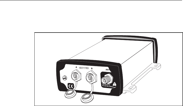
2.2 Receiver Connections
Figure 2.1 shows the connector ports on the AgGPS 332 receiver.
Figure 2.1 AgGPS 332 receiver connector ports
The two connectors (Port A and Port B) can perform the following
functions:
•accept power
•accept TSIP, RTCM, ASCII, and (if enabled) CMR inputs
•output RTCM, TSIP, and NMEA messages
•output 1 PPS signals
•provide support for the J1939 (CAN) serial bus
For more information about the inputs, outputs, and LCD display, see
the information in the rest of this section.

AgGPS 332 GPS Receiver User Guide 7
Overview 2
2.3 Receiver Input/Output
The AgGPS 332 receiver data/power cable (P/N 30945) connects to a
receiver connector port to supply power. It also enables the following
data exchanges:
•TSIP, RTCM, and ASCII input from an external device
The receiver is able to receive ASCII data from an external
device, convert this data into an NMEA message, and export the
message to another device. TSIP command packets configure
and monitor GPS and DGPS parameters. The receiver is also able
to accept RTCM data from an external device, such as a radio.
•CMR input from an external device
If the receiver is to be used in RTK mode, set the port that is
connected to the radio to the RtkLnk protocol. This protocol
enables the receiver to receive CMR messages.
•TSIP and NMEA output to an external device
When you are using an external radio, the receiver can also
receive DGPS corrections.
NMEA is output when the receiver is exporting GPS position
information to an external device, such as a yield monitor, or to a
mapping software program.
For more information on the National Marine Electronics
Association (NMEA) and Radio Technical Commission for
Maritime Services (RTCM) communication standard for GPS
receivers, go to the following websites:
–www.nmea.org
– www.rtcm.org
On the Trimble website (www.trimble.com), refer to the
document called NMEA-0183 Messages Guide for AgGPS
Receivers.

2 Overview
8 AgGPS 332 GPS Receiver User Guide
•1 PPS output
To synchronize timing between external instruments and the
internal clock in the receiver, the connection port outputs a
strobe signal at 1 PPS (pulse per second). To output this signal,
the receiver must be tracking satellites and computing GPS
positions.
•J1939 (CAN) bus
Both connection ports on the receiver support the J1939
Controller Area Network (CAN) bus protocol. This protocol
standardizes the way multiple microprocessor-based electronic
control units (ECUs) communicate with each other over the
same pair of wires. It is used in off-highway machines, such as
those used in agriculture, construction, and forestry.
For more information, go to the Society of Automotive Engineers
(SAE) International website at www.sae.org/servlets/index.
•ISO 11783 messages
Both CAN ports support some ISO 11783 messages.
Position output format
The AgGPS receiver outputs positions in Degrees, Minutes, and
Decimal Minutes (DDD°MM.m'). This is the NMEA standard format
and is commonly used worldwide for data transfer between electronic
equipment.
AgGPS 332 GPS Receiver User Guide 9
Overview 2
2.4 GPS Positioning Methods
GPS positioning systems are used in different ways to provide different
levels of accuracy. Accuracy is measured in absolute terms (you know
exactly where you are in a fixed reference frame).
Table 2.1 summarizes the GPS positioning methods. Imperial units in
this table are rounded to two decimal places. The values shown are
2sigma.
For more information about each positioning method, see below.
24.1 RTK GPS positioning
The AgGPS 332 receiver uses the RTK positioning method to achieve
centimeter-level accuracy. To use the RTK method, you must first set
up a base station. The base station uses a radio link to broadcast RTK
corrections to one or more rover receivers. The AgGPS 332 receiver is a
rover receiver, so another compatible receiver, such as a Trimble
MS750™ or AgGPS 214 GPS receiver, must be used as the base station.
Table 2.1 Absolute accuracy of GPS positioning method
GPS positioning
method
Corrections used Approximate absolute accuracy
Real-Time Kinematic
(RTK) GPS
Trimble CMR
corrections broadcast
by a local base station
2.5 cm (0.98 in) + 2 ppm horizontal accuracy,
3.7 cm (1.46 in) + 2 ppm vertical accuracy
OmniSTAR HP
Differential GPS
OmniSTAR HP 10 cm (3.94 in) after the signal has fully
converged1
1Convergence time can vary, depending on the environment. Time to the first fix (submeter accuracy) is
typically <30 seconds; time to the first high accuracy fix (<10 cm accuracy) is typically <30 minutes.
OmniSTAR XP
Differential GPS
20 cm (7.87 in) after the signal has fully
Differential GPS converged
Satellite Differential GPS OmniSTAR VBS 78 cm (30.71 in)
Radio Beacon Coast Guard radio
beacon towers
.4 inch through 12 inch
(10 cm through 30 cm) RMS 15 min
Satellite Differential GPS WAAS/EGNOS 95 cm (37.40 in)

2 Overview
10 AgGPS 332 GPS Receiver User Guide
A transmitter in the base station sends the corrections through a radio
link to the rover radio, which sends the corrections to the AgGPS 332
receiver. The rover receiver uses RTK corrections from the base station
to calculate its position to centimeter-level accuracy. As part of this
process, the rover receiver must calculate an initialization. This takes a
few seconds. While the receiver is initializing, an RTK Float solution is
generated. Once initialized, an RTK Fixed solution is generated. It is the
RTK Fixed solution that provides centimeter-level accuracy.
The parts per million (ppm) error is dependent on the distance
(baseline length) between the base and rover receiver. For example, if
the distance is 10 km, a 2 ppm error equals 20 mm.
For more information about RTK positioning, go to the Trimble website
at www.trimble.com/gps/.
24.2 Differential GPS positioning (DGPS)
For differential positioning, the AgGPS 332 receiver uses corrections
from SBAS (WAAS/EGNOS)/OmniSTAR satellites and Radio Beacons.
These differential systems use special algorithms to provide differential
corrections that allow the rover receiver to calculate its position more
accurately.
Free corrections
WAAS/EGNOS corrections are free in North America and Europe.
For more information about WAAS, go to the Federal Aviation
Administration website at
http://gps.faa.gov/Programs/WAAS/waas.htm.
For more information about EGNOS, go to the European Space Agency
website at
www.esa.int/export/esaSA/GGG63950NDC_navigation_0.html.
Radio Beacon corrections are available free worldwide. For more
information about the Coast Guard Beacon, go to
www.navcen.uscg.gov/Default.htm.

AgGPS 332 GPS Receiver User Guide 11
Overview 2
Subscription-based corrections
The AgGPS 332 receiver uses OmniSTAR XP/HP or OmniSTAR VBS
differential corrections in the same way that it uses WAAS/EGNOS
corrections but are provided on a subscription basis.
The corrections that are produced by OmniSTAR XP/HP algorithms are
more accurate than the corrections that are produced by OmniSTAR
VBS algorithms. The accuracy of the positions reported using
OmniSTAR HP/XP increases with the time that has elapsed since the
instrument was turned on. This process is called convergence.
Convergence to where the error is estimated to be below 30 cm
(approximate 12 inches) typically takes around 20 minutes. Factors that
influence the time to convergence include the environment, the
geographical location and for OmniSTAR HP, the distance to the
closest OmniSTAR corrections base station. OmniSTAR is continually
improving this service. OmniSTAR XP is not dependent on distance to
base station
For more information about OmniSTAR, go to the OmniSTAR website
at www.omnistar.com. Alternatively, call 888 883 8476 (USA or Canada).
For information about activating an OmniSTAR subscription, go to the
OmniSTAR website (www.omnistar.com) or call 888-883-8476 (USA or
Canada).
24.3 Autonomous GPS positioning
Autonomous GPS positioning uses no corrections. The rover receiver
calculates its position using only the GPS signals it receives. This
method does not have high absolute accuracy, but the relative accuracy
can be comparable depending on geographic location and overall
environment.

2 Overview
12 AgGPS 332 GPS Receiver User Guide
24.4 Sources of Error in GPS Positioning
The GPS positioning method influences the accuracy of the GPS
position that is output by the AgGPS 332 receiver. The factors described
in Table 2.2 also affect GPS accuracy.
Table 2.2 Factors that influence the accuracy of GPS positions
Condition Optimum
value
Description
Atmospheric
effects
GPS signals are degraded as they travel through the
ionosphere. The error introduced is in the range of 10 meters.
The error is removed by using a differential or RTK positioning
method.
Number of
satellites used
> 5 To calculate a 3D position (latitude and longitude, altitude,
and time), four or more satellites must be visible. To calculate a
2D position (latitude and longitude, and time), three or more
satellites must be visible. For RTK positioning, five satellites are
needed for initialization. Once initialized, four or more
satellites provide RTK positions. The number of visible satellites
constantly changes and is typically in the range 5 through 9.
The AgGPS receiver can track up to 12 satellites simultaneously.
Note – To see when the maximum number of GPS satellites are
available, use the Trimble Planning software and a current
ephemeris (satellite history) file. Both files are available free
from the Trimble website at www.trimble.com.
Maximum PDOP < 4 Position Dilution of Precision (PDOP) is a unitless, computed
measurement of the geometry of satellites above the current
location of the receiver. A low PDOP means that the
positioning of satellites in the sky is good, and therefore good
positional accuracy is obtained.
Signal-to-noise
ratio
> 6 Signal-to-noise ratio (SNR) is a measure of the signal strength
against electrical background noise. A high SNR gives better
accuracy.
Normal values are:
•GPS 6
•WAAS 3+
•Beacon 12+
•OmniSTAR XP/HP/VBS 6+

AgGPS 332 GPS Receiver User Guide 13
Overview 2
Minimum
elevation
> 10 Satellites that are low on the horizon typically produce weak
and noisy signals and are more difficult for the receiver to
track. Satellites below the minimum elevation angle are not
tracked.
Multipath
environment
Low Multipath errors are caused when GPS signals are reflected off
nearby objects and reach the receiver by two or more different
paths. The receiver incorporates the EVEREST multipath
rejection option.
RTCM-compatible
corrections
These corrections are broadcast from a Trimble 4000RSi, or
equivalent reference station.
RTK base station
coordinate
accuracy
For RTK positioning, it is important to know the base station
coordinates accurately. Any error in the position of the base
station affects the position of the rover; every 10 m of error in
a base station coordinate can introduce up to 1 ppm scale error
on every measured baseline. For example, an error of 10 m in
the base station position produces an error of 10 mm over a
10 km baseline to the rover.
For more information about how to make sure the position of
your base station is accurate, refer to the manual for your base
station receiver.
Multiple RTK
base stations
If you are using several base stations to provide RTK
corrections to a large site area, all base stations must be
coordinated relative to one another. If they are not, the
absolute positions at the rover will be in error. For more
information about how to use several base stations to cover
your site, contact your local Trimble Reseller.
Table 2.2 Factors that influence the accuracy of GPS positions (continued)
Condition Optimum
value
Description

2 Overview
14 AgGPS 332 GPS Receiver User Guide
24.5 Coordinate systems
Geographic data obtained from different sources must be referenced to
the same datum, ellipsoid, and coordinate format. Different formats
provide different coordinate values for any geographic location. In
North America, the datums NAD-27 and NAD-83 are commonly used in
Agricultural mapping applications.
The AgGPS 332 receiver outputs position coordinates in several datums
and ellipsoids depending on the GPS positioning method being used.
See Table 2.3.
For more information, go to the National Geodetic Survey website at
www.ngs.noaa.gov/faq.shtml#WhatDatum.
Table 2.3 DGPS coordinate systems
GPS positioning method Datum Ellipsoid
None – Autonomous mode WGS-84 1WGS-84
OmniSTAR VBS North American Beams NAD-83 2GRS-80
OmniSTAR VBS Rest of World Beams ITRF 3GRS-80
OmniSTAR HP ITRF 2000 ITRF 2000
WAAS Beams WGS-84 WGS-84
Beacon NAD-83 NAD-83
OmniSTAR XP ITRF 2000 ITRF 2000
RTK WGS-84 WGS-84
1 World Geodetic System (WGS) 1984. Datum and ellipsoid.
2 North American Datum (NAD) 1983. Equivalent to WGS-84 in North
America.
3 International Terrestrial Reference Frame (ITRF). Contact the DGPS provider for details.

AgGPS 332 GPS Receiver User Guide 15
Overview 2
24.6 Satellite DGPS mode status indicators
When the receiver is in Satellite mode, the second line of the Home
screen displays the status indicators shown in Figure 2.2.
Figure 2.2 Satellite DGPS mode status indicators
Table 2.4 shows the possible satellite differential mode indicators.
Table 2.5 explains the signal-to-noise ratio values for both Satellite
and WAAS/EGNOS DGPS modes.
Table 2.4 Satellite differential mode status indicators
Indicator Description
S ####.### S/N ## Operating in Satellite Differential mode.
S SRCH ###.## Searching for Satellite Differential signal.
S TRCK ####.## Tracking satellite without acquiring signal lock.
Table 2.5 Signal-to-noise values
Value Description
Below 4 Unusable
4–8 Fair
>8 Excellent
S 1556.2550 ÷ø10
Receiver is using Satellite DGPS corrections.
Frequency for tracked DGPS satellite. Available
frequencies vary according to your location and
DGPS service provider.
Signal-to-noise ratio of
DGPS signal, see Table 2.5.

2 Overview
16 AgGPS 332 GPS Receiver User Guide
24.7 Receiver input / output
The receiver is able to output RTCM in base station mode. When you
are using an external radio, it can also receive DGPS corrections. NMEA
is output when the receiver is exporting GPS position information to an
external device, such as a yield monitor or to a mapping software
program.
24.8 DGPS accuracy
Submeter accuracy from the AgGPS 332 receiver utilizing differential
correction is best achieved under the conditions described in Table 2.6.
Table 2.6 DGPS accuracy
Condition Optimum
Value
Description
To calculate a 3D position (latitude and longitude, altitude, and
time), four or more satellites must be visible.
To calculate a 2D position (latitude and longitude, and time),
three or more satellites must be visible.
The number of visible satellites constantly changes and is
typically in the range 5–9. Ag
to 12 satellites simultaneously.
Note – To see when the maximum number of GPS satellites
are available, use the Quickplan utility and a current
ephemeris (satellite history) file. Both files are available free
from: www.trimble.com/support_trl.asp?Nav=Collection-3627.
Maximum PDOP < 4 Position Dilution of Precision (PDOP) is a unitless, computed
measurement of the geometry of satellites above the
receiver’s current location.
Note – In some agricultural applications that do not require
high accuracy, a maximum PDOP of 12 or more can be used.
> 6 Signal-to-Noise ratio (SNR) is a measure of the satellite signal
strength against electrical background noise. A high SNR
gives better accuracy.
Minimum
Elevation
> 7.5 Satellite that are low on the horizon typically produce weak
and noisy signals and are more difficult for the receiver to
track. Satellites below the minimum elevation angle are not
tracked.

AgGPS 332 GPS Receiver User Guide 17
Overview 2
24.9 Receiving Beacon DGPS
To obtain free radiobeacon differential signals, the AgGPS 332 receiver
uses dual-channel, fully-automatic beacon receiver electronics and
tracks broadcasts that conform to the IALA (International Association
of Lighthouse Authorities) Standard. When you use beacon DGPS, the
receiver selects the closest of the 10 most powerful radiobeacons in the
vicinity. You can configure the receiver to search for particular station
frequencies, or use the EZ beacon feature to select local beacons.
The receiver continuously monitors the integrity of the data received
from the differential radiobeacons. If it finds unacceptable errors in the
data stream, the receiver automatically switches to a different
radiobeacon, if one is available.
Radiobeacon signal reception is generally not affected by:
•hilly or mountainous terrain
•tree canopy
•location of the receiver inside a canyon (the signal reception
depends on the proximity of the receiver to the transmitter)
Radiobeacon signal reception is affected to varying degrees, by:
•natural “noise”, such as lightning
•human-made “noise”, such as alternators, electric fan motors,
radio speakers, and high voltage power lines
Multipath
environment
Low Multipath errors are caused when GPS signals are reflected
off nearby objects and reach the receiver by two or more
different paths. The receiver incorporates the EVEREST
multipath reduction option.
RTCM-
compatible
corrections
These corrections are broadcast from a Trimble 4000RSi™ or
equivalent reference station.
Table 2.6 DGPS accuracy (continued)

2 Overview
18 AgGPS 332 GPS Receiver User Guide
•Sky wave interference with ground wave
During darkness, when the beacon tower is more than 240–
480 kilometers (150–300 miles) from the receiver, the sky wave
beacon signal may be reflected off the ionosphere. This causes
interference with the ground wave beacon signal. Self-jamming
at night may be a problem with stronger beacon stations.
•Geographic de-correlation
This phenomenon causes radiobeacon signal accuracy to
decrease as the distance between the beacon tower and the base
station increases. Ionospheric conditions can affect accuracy by
as much as 1 meter (3 feet) for every 100 km (60 miles).

CHAPTER
3
AgGPS 332 GPS Receiver User Guide 19
Connecting the Receiver 3
QIntroduction
QSystem Components
QMounting the Receiver
QConnecting to an External Device
QSystem Components
QRouting and Connecting the Antenna Cable
QConnecting to the EZ-Guide Plus System
QConnecting to the EZ-Steer Assisted Steering System
QConnecting to a Laptop Computer
QConnecting to a Windows Handheld Computer

3 Connecting the Receiver
20 AgGPS 332 GPS Receiver User Guide
3.1 Introduction
This chapter describes how to check the equipment that you have
received, set up the receiver, and connect the receiver to another
device.
3.2 System Components
Check that you have received all components for the AgGPS system
that you have purchased. If any containers or components are
damaged, immediately notify the shipping carrier. Table 3.1 and
Table 3.2 lists the components.
32.1 Optional components
You may also have ordered the following item:
For ordering and pricing details, contact your local Trimble Reseller.
Table 3.1 AgGPS 332 receiver (P/N 55580-xx)
Quantity Description
1 AgGPS 332 DGPS receiver (P/N 55580)
1 Power Data Cable (P/N 30945)
1AgGPS 332 GPS Receiver User Guide
(this manual, P/N 56370-00-ENG)
1 Warranty Activation Card (P/N 25110-00)
1 OmniSTAR Activation Card (P/N 33965)
1 Antenna (P/N 33580-00 or P/N 56981)
Table 3.2 Receiver option
Quantity Description
1 RTK capability (P/N 51264)
1 OmniSTAR XP/HP upgrade (P/N 55951)

AgGPS 332 GPS Receiver User Guide 21
Connecting the Receiver 3
3.3 Mounting the Receiver
CWARNING – For continued protection against the risk of fire, the power
source (lead) to the model AgGPS 332 receiver should be provided with a
10 A (maximum) fuse.
33.1 Choosing a location
When choosing a location, consider the following:
Mount the receiver:
•on a flat surface along the centerline of the vehicle
•in any convenient location that is within 5.5 meters (18 ft) of the
port on the external instrument; if necessary, use the optional
extension cable to connect the receiver and external device
Note – If you are using a Trimble AgGPS Autopilot system, refer to
the installation instructions that are provided with the Autopilot.
•at the highest point on the vehicle, with no metal surfaces
blocking the receiver’s view of the sky
•in such a way that it is not damaged when you drive the machine
into a shed or storage area
Do not mount the receiver:
•close to stays, electrical cables, metal masts, CB radio antennas,
cellular phone antennas, air-conditioning units (machine cab
blower fan), or machine accessory lights
•near transmitting antennas, radar arrays, or satellite
communication equipment
•near areas that experience high vibration, excessive heat,
electrical interference, and strong magnetic fields
Note – A metal combine grain tank extension can block satellites.

3 Connecting the Receiver
22 AgGPS 332 GPS Receiver User Guide
33.2 Environmental conditions
Although the receiver has a waterproof housing, you should install it in
a dry location. To improve the performance and long-term reliability of
the receiver, avoid exposure to extreme environmental conditions,
including:
•water
•excessive heat (> 70 °C or 158 °F)
•excessive cold (< –30 °C or –22 °F)
•high vibration
•corrosive fluids and gases
33.3 Electrical interference
As far as possible, when you install the receiver, you should avoid
placing it near sources of electrical and magnetic noise, such as:
•gasoline engines (spark plugs)
•computer monitor screens
•alternators, generators, or magnetos
•electric motors (blower fans)
•equipment with DC-to-AC converters
•switching power supplies
•radio speakers
•high-voltage power lines
•CB radio antennas
•cellular phone antennas
•machine accessory lights
AgGPS 332 GPS Receiver User Guide 23
Connecting the Receiver 3
3.4 Connecting to an External Device
After installing the receiver and connecting the appropriate cabling,
you can connect the receiver to various external devices. For example:
Figure 3.1 shows how to connect the receiver to an external device
using the Power data cable.
Figure 3.1 Standard power/data cable connections
To connect the AgGPS 332 receiver to ... use the cable ...
an EZ-Guide Plus system P/N 30945
an Autopilot system P/N 54609
a Field computer P/N 30945
a Yield monitor P/N 30945
a Trimble SiteNet™ radio, for RTK positioning P/N 39941
multiple devices (access to ports A, B, and C) P/N 37382
+
-

3 Connecting the Receiver
24 AgGPS 332 GPS Receiver User Guide
When routing the cable from the receiver to the external device, avoid:
•sharp objects
•kinks in the cable
•hot surfaces (exhaust manifolds or stacks)
•rotating or moving machinery parts
•sharp or abrasive surfaces
•door and window jams
•corrosive fluids or gases
When the cable is safely routed and connected to the receiver, use
tie-wraps to secure it at several points, particularly near the base of the
receiver, to prevent straining the connection. Coil any slack cable,
secure it with a tie-wrap, and tuck it into a safe place.
The external device may have to be configured to work with the AgGPS
receiver. The configuration tools for the external device should be
provided with the device. For more information about configuring the
receiver, see Chapter 5, Configuring the Receiver. For information
about connecting a particular external device, refer to the manual for
that device or contact your local Trimble Reseller.
AgGPS 332 GPS Receiver User Guide 25
Connecting the Receiver 3
3.5 System Components
Mount the receiver on a level, flat surface. To mount it on a ceiling,
contact your local Trimble Reseller for the appropriate bracket. Place
the antenna upright with the magnetic base on a flat metal surface.
Note – A metal combine grain tank extension can block satellites.
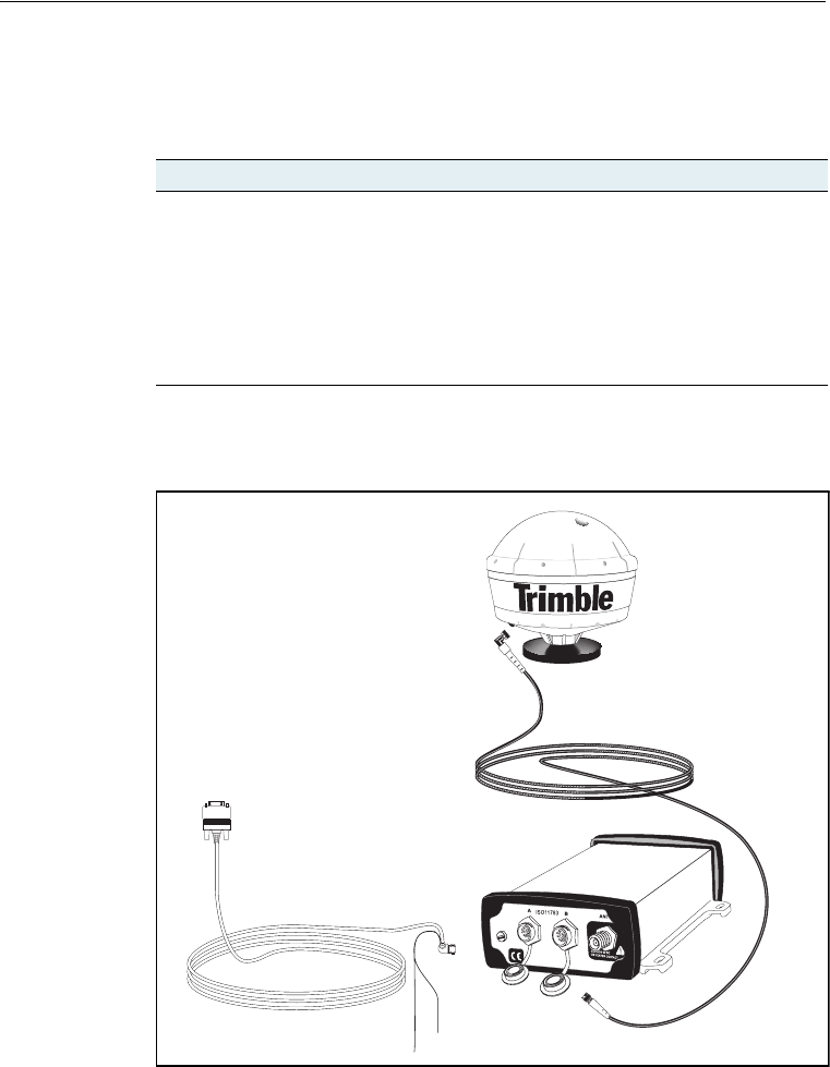
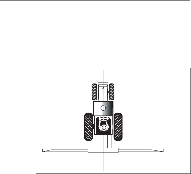
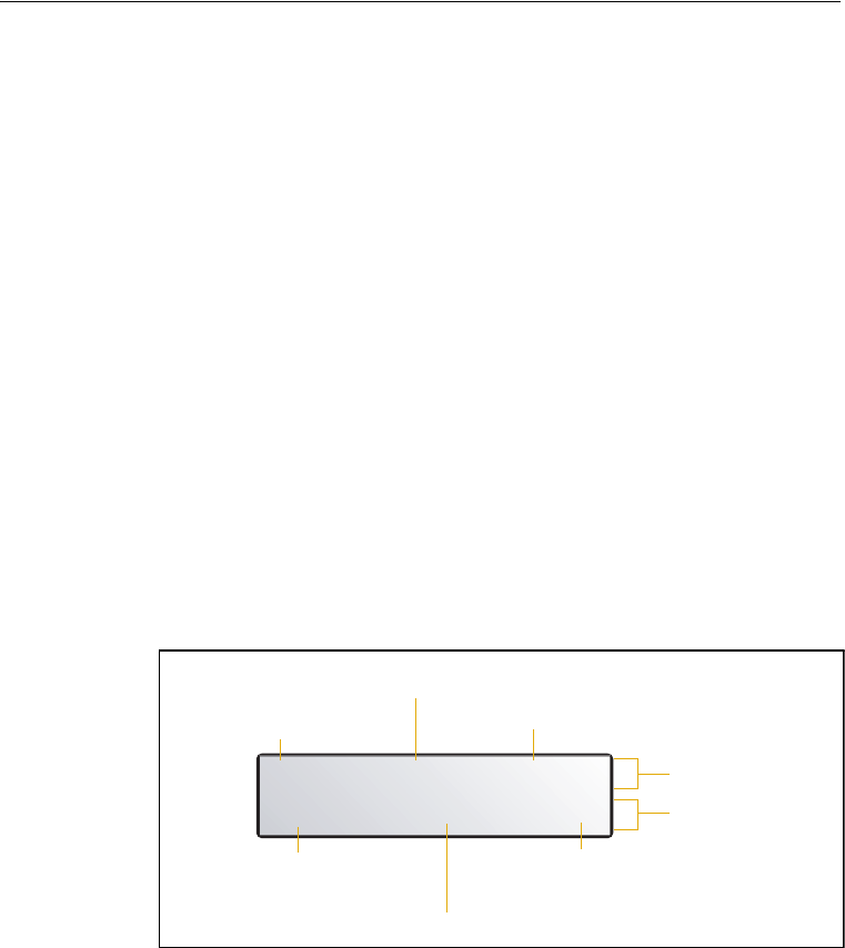
Figure 3.2 shows the recommended location for sprayer boom
applications.
Figure 3.2 AgGPS 332 receiver antenna mounting for ground sprayer
boom applications
35.1 The receiver
To mount the AgGPS 332 receiver:
1. Drill four holes in the mounting surface. Use the slotted holes in
the mounting brackets as a template.
2. Use screws to secure the brackets to the mounting surface.
Boom centerline
Application boom
Antenna
3 Connecting the Receiver
26 AgGPS 332 GPS Receiver User Guide
Note – If you use machine screws, tap the mounting holes to fasten the
receiver to the mounting surface. Trimble recommends that you use 8-32
UNF socket head cap screws. Alternatively, use self-tapping screws.
30.1 The antenna
Mount the antenna where it is safe from damage during normal
operation.
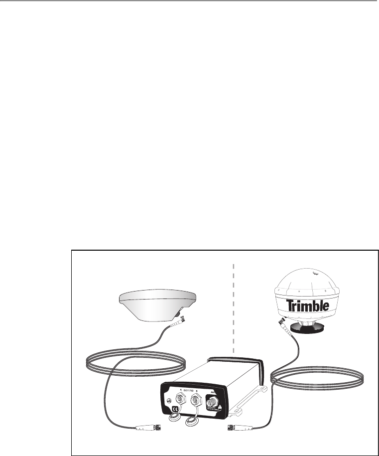
3.1 Routing and Connecting the Antenna Cable
A 5.5 m (18 ft) antenna cable (P/N 32608) is included with the receiver.
See Figure 3.3. One end of the antenna cable features a right-angle
connector. The opposite end features a straight connector. Connect the
right-angle connector to the antenna; then route the cable to the
receiver.
Figure 3.3 Antenna cable connections
Antenna cable
P/N 32608
Antenna cable
P/N 32608
SPOT antennaorZ+ antenna

AgGPS 332 GPS Receiver User Guide 27
Connecting the Receiver 3
When routing the antenna cable, avoid the following hazards:
•sharp objects
•kinks in the cable
•hot surfaces (exhaust manifolds or stacks)
•rotating or moving machinery parts
•sharp or abrasive surfaces
•door and window jams
•corrosive fluids or gases
After routing the cable, connect it to the receiver. Use tie-wraps to
secure the cable at several points along the route. One tie-wrap is
required to secure the cable near the base of the antenna. This provides
strain relief for the antenna cable connection.
When the cable is secured, coil any slack. Secure the coil with a
tie-wrap and tuck it into a safe place.
BTip – Use the tape (coax tape seal) that is provided with the antenna to
seal the antenna connector at the antenna. The tape prevents moisture
from entering the connection.
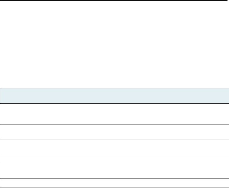
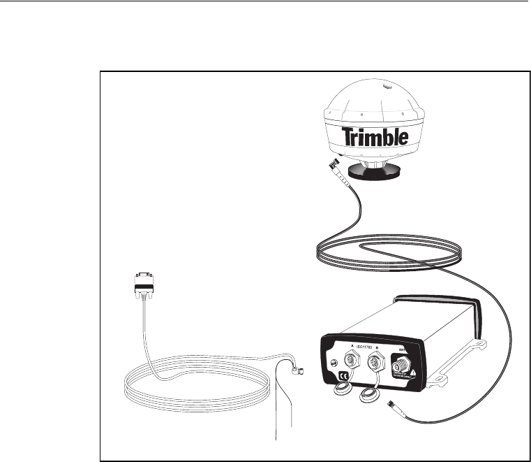
After installing the receiver and antenna, connect and route the
power/data cable (P/N 30945). The receiver can be powered by a
vehicle or by a customer-supplied 10–32 V DC power source.
3 Connecting the Receiver
28 AgGPS 332 GPS Receiver User Guide
Figure 3.4 shows how to connect the receiver to an external device
using the 5.5 m (18 ft) standard power/data cable.
Figure 3.4 Standard power/data cable connections
Plug the:
•right-angle connector into the receiver
•straight 9-pin connector into the external device
When routing the cable from the receiver to the external device, avoid
the hazards listed on page 27.
When the cable is safely routed and connected to the receiver, use
tie-wraps to secure it at several points, particularly near the base of the
receiver to prevent straining the connection. Coil any slack cable,
secure it with a tie-wrap and tuck it into a safe place.
+
-
Ground -ve Black
9-pin port
Connect cable
Connect antenna
cable to coaxial connection
P/N 30945 to Port A
Power +ve Red
AgGPS 332 GPS Receiver User Guide 29
Connecting the Receiver 3
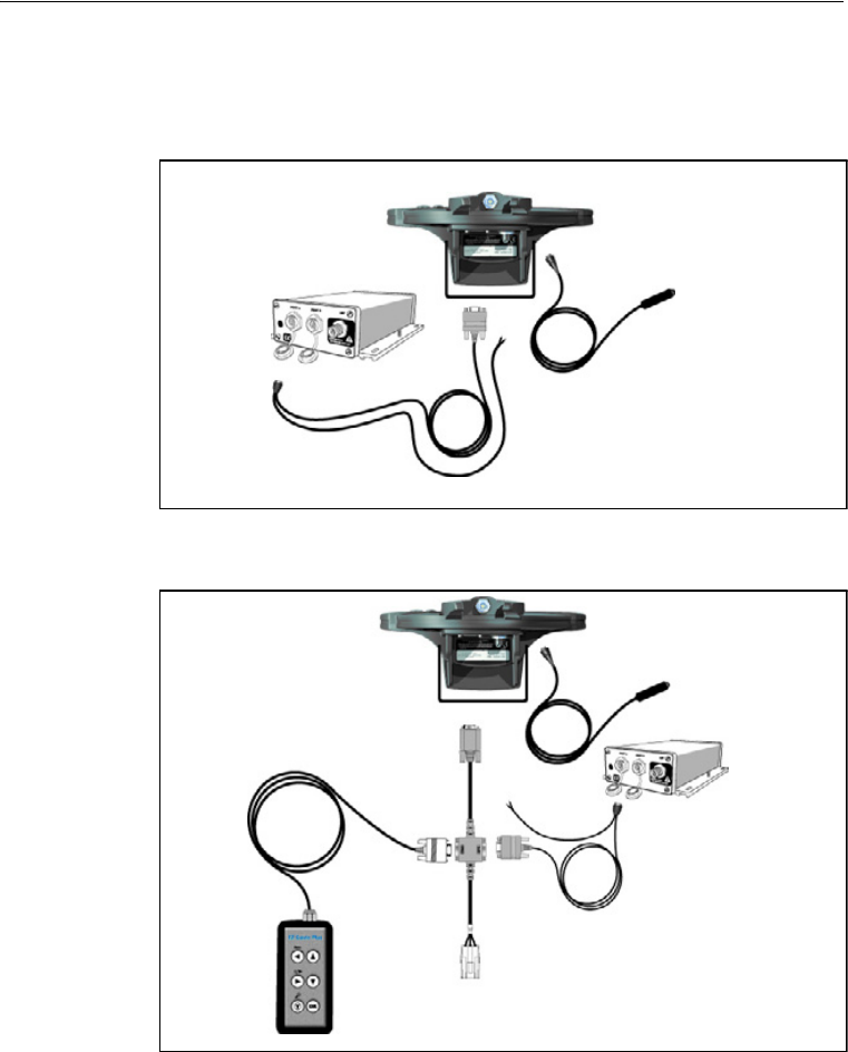
3.2 Connecting to the EZ-Guide Plus System
Figure 3.5 and Figure 3.6 show how to connect the AgGPS 332 receiver
to the AgGPS EZ-Guide Plus system.
Figure 3.5 Connecting the AgGPS 332 receiver to the AgGPS EZ-Guide
Plus system without the remote control
Figure 3.6 Connecting the AgGPS 332 receiver to the AgGPS EZ-Guide
Plus system with the remote control
P/N 30945
To power
To power
P/N 52033
To power
P/N 30945
To power
3 Connecting the Receiver
30 AgGPS 332 GPS Receiver User Guide
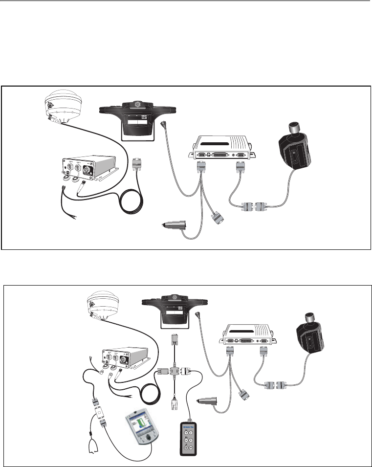
3.3 Connecting to the EZ-Steer Assisted Steering
System
Figure 3.7 and Figure 3.8 show how to connect the AgGPS 332 receiver
to the AgGPS EZ-Steer assisted steering system.
Figure 3.7 Connecting the AgGPS 332 receiver to the AgGPS EZ-Steer assisted steering
system with the remote control
Figure 3.8 Connecting the AgGPS 332 receiver to the AgGPS EZ-Steer assisted steering
system with the remote control and Pocket PC for field mapping capability
T
r
i
m
b
l
e
P/N 52764
P/N 30945
To power
P/N 52763
To power
T
r
i
m
b
l
e
To power
P/N 30945
P/N 46635
P/N 52764
To power
P/N 30945
P/N 52033
P/N 52763
AgGPS 332 GPS Receiver User Guide 31
Connecting the Receiver 3
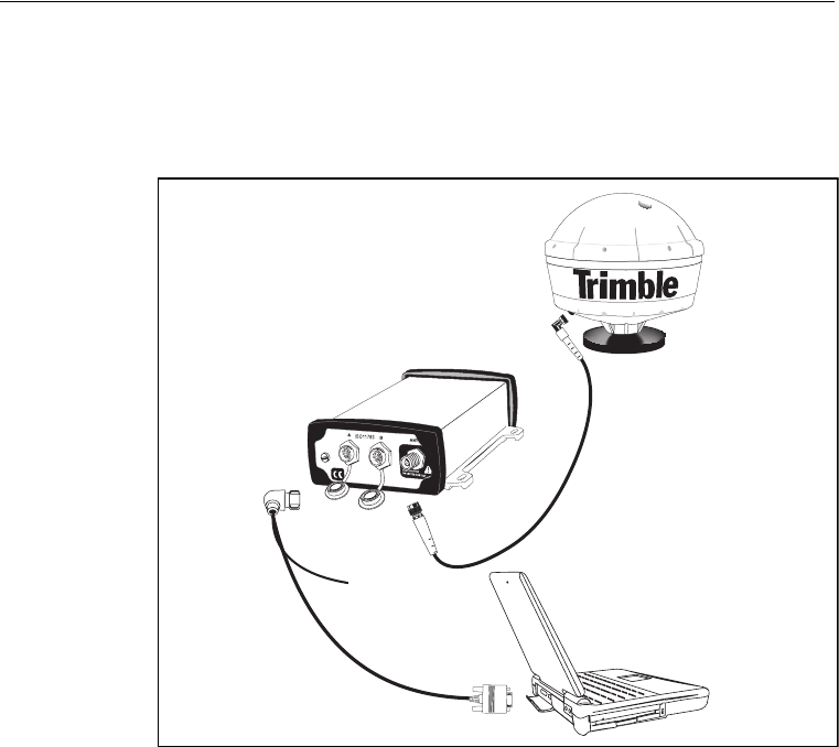
3.4 Connecting to a Laptop Computer
Figure 3.9 shows how to connect the receiver power/data cable to a
laptop computer.
Figure 3.9 Connecting the receiver to a laptop computer
9-pin port
Connect cable
P/N 30945 to Port A
Connect antenna cable
to Port B
3 Connecting the Receiver
32 AgGPS 332 GPS Receiver User Guide
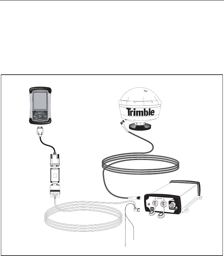
3.5 Connecting to a Windows Handheld Computer
Figure 3.10 shows how to connect the receiver power/data cable to a
Windows CE handheld computer.
Note – To connect the receiver to a Compaq iPAQ handheld computer,
you require a RS232 9-pin serial cable (PN 236251-B21). This cable is
available from Compaq.
Figure 3.10 Connecting the receiver to a Windows CE handheld computer
Windows CE
cable
Null modem
adaptor
9-pin connector
Ground -ve Black
Power +ve Red
Connect cable
Connect antenna cable
to Port B
P/N 30945 to Port A

4 Getting Started
34 AgGPS 332 GPS Receiver User Guide
4.1 Introduction
This chapter describes how to set up and begin using the AgGPS 332
receiver. It includes an overview of the AgGPS menu system.
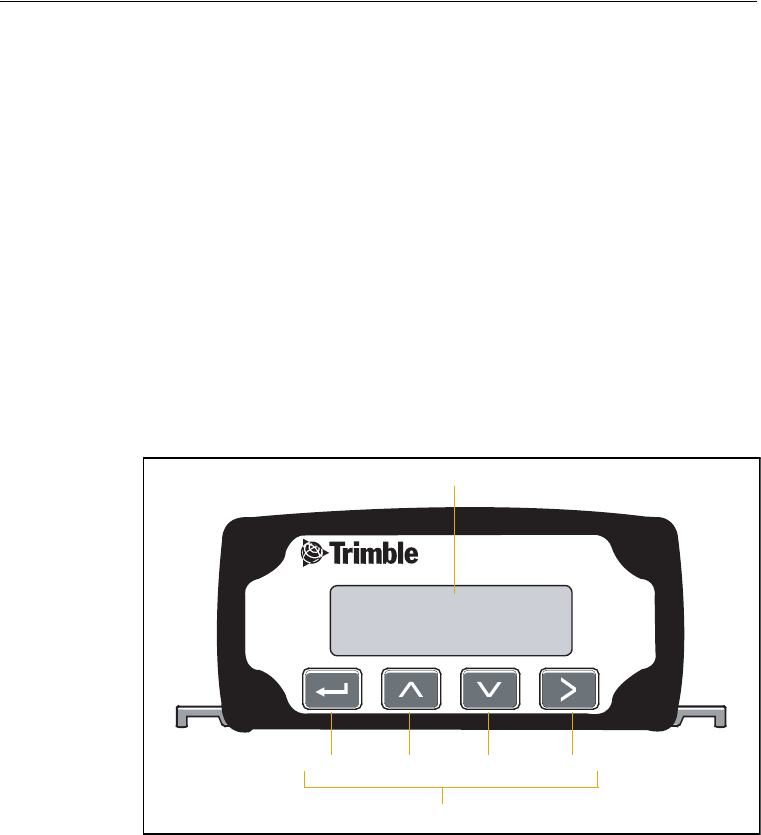
4.2 Front Panel
The AgGPS 332 receiver includes an integrated display and keypad for
accessing the internal AgGPS menu system. Use the menus and screens
in this system to configure the receiver settings and review receiver
status. To view the entire AgGPS menu system, go to the Trimble
website (www.trimble.com/aggps332_ts.asp).
Figure 4.1 shows the LCD display and keypad on the AgGPS 332
receiver front panel.
Figure 4.1 The AgGPS 332 receiver front panel

AgGPS 332 GPS Receiver User Guide 35
Getting Started 4
4.3 Navigating the Menus and Screens
Note – Use a menu to navigate to screens or other menus. Use a screen to
view the receiver status or to change a configuration setting.
The top level of the menu system consists of the Home, Status, and
Configuration menus. Each of these has one or more lower level menus
(sub-menu) which you can use to access screens for selecting options,
viewing status information, and entering data. For a map showing the
full menu system, go to the Trimble website
(www.trimble.com/aggps332_ts.asp).
When you are using the receiver front panel keypad to navigate the
menu system, press 2+1 simultaneously to move to the previous
menu. Press and hold (or press repeatedly) 2+1 simultaneously to
return to the Home screen.
4 Getting Started
36 AgGPS 332 GPS Receiver User Guide
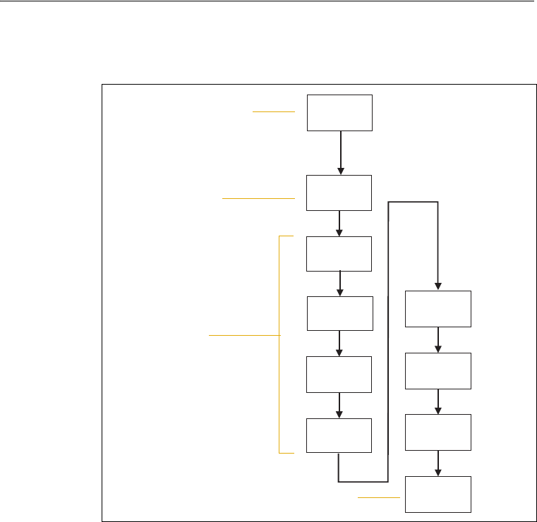
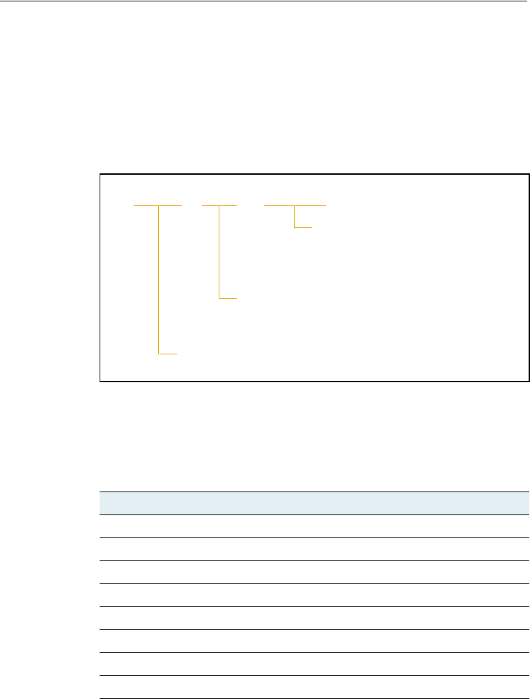
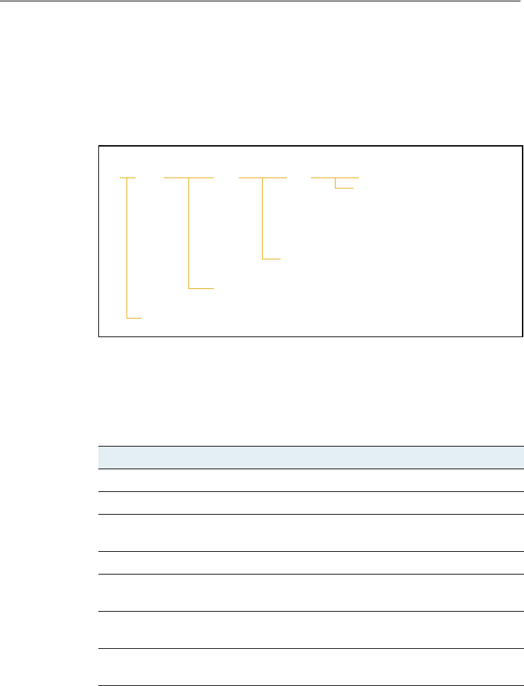
Figure 4.2 shows the structure of a typical sub-menu, for example
Display Options.
Figure 4.2 Typical menu structure
Press 2 or 1 to move between screens. Within screens, select
options, view receiver status, or enter data. When Ð appears in a
screen, press 4 to perform the action specified for that screen.
Top-level menu screen
Sub-menu screen
Screens
Home
Display
Options
1
Contrast
Lock
Display
Language
Units
Clear
Memory
Exit
1
12
1
12
2
1
12
2
21
2
2
Update
Receiver
User Level
12
Exit screen indicates end of the menu
AgGPS 332 GPS Receiver User Guide 37
Getting Started 4
4.4 Menu System Fields
Fields in a screen contain status information or configuration settings.
The information or settings appear in fields that are:
•display-only
•multiple-choice
•text
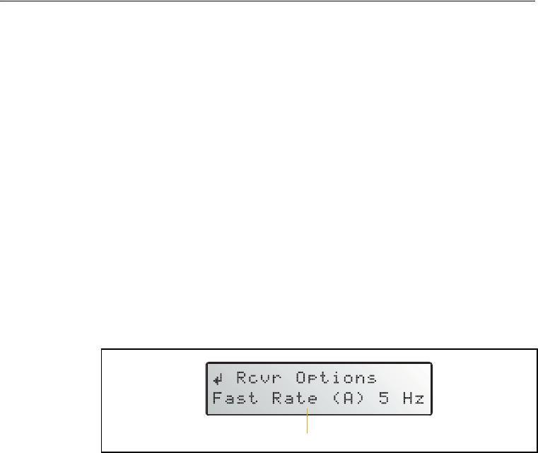
44.1 Display-only fields
A display-only field shows status information and other data that is
automatically generated by the receiver or acquired from satellite
signals. You cannot edit this field. Examples include fields that display
the DGPS data on the Home screen and the fields in the screen in
Figure 4.3, which show details of the current receiver options.
Figure 4.3 Example of a display-only field
44.2 Multiple-choice fields
In a mulitple-choice field, you select one option from a list. Only one
option can appear in the field at one time. Press 3 to select a
multiple-choice field, the press 2 or 1 to move through the list.
When the required option appears, press 4 to select it and save the
changes.
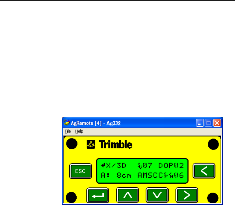
Examples include the two multiple-choice fields that appear in the EZ
Sat DGPS Configuration screen (see Figure 4.4). These are the fields
which list available satellite providers, and satellite coverage beams.
Receiver options details field

4 Getting Started
38 AgGPS 332 GPS Receiver User Guide
Figure 4.4 Example of a multiple-choice field
44.3 Text fields
In these fields, you can enter only letters (alpha screens), only numbers
(numeric screens), or a combination of the two (alphanumeric screens):
1. Press 3 to select the field and activate the cursor on the first
letter or number.
2. Press 1 or 2 to move through the list of letters or numbers
until the required letter or number appears.
3. Press 3 to move to the next place in the field.
4. Repeat Step 2 through Step 3 to enter all required characters.
5. Press 4 to save the changes.
Service Provider field
Satellite Coverage Beam field
AgGPS 332 GPS Receiver User Guide 39
Getting Started 4
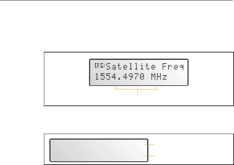
4.1 The Home Screen
One example of a numeric field appears in the Satellite Freq screen. You
manually enter the broadcast frequency of a satellite service provider.
See Figure 4.5.
Figure 4.5 Example of a numeric field
When you start the receiver, the Home screen appears. See Figure 4.6.
Figure 4.6 The Home Screen
You can leave this screen running during operation. It enables you to
monitor the receiver status. To return to the Home screen after viewing
other receiver menus and screens, press 5 one or more times.
The AgGPS 332 receiver is a combined Beacon and Satellite DGPS
receiver. The information that appears on the Home screen depends on
how the receiver is configured.
41.1 Satellite DGPS mode
In this manual, references to Satellite DGPS apply only to the AgGPS
332 receiver. When the receiver is in Beacon DGPS mode, a B, Beacon
Searching, Beacon Tracking, or Beacon FFT message appears in the
lower-left corner of the screen. To change between modes, press 4
and hold for five seconds. To display satellite differential information,
press 4 until an S appears in the lower left corner of the screen.
Satellite Frequency field
Srch í00 DOP00
S 1556.0000 Srch
GPS status indicators
Satellite DGPS indicators
4 Getting Started
40 AgGPS 332 GPS Receiver User Guide
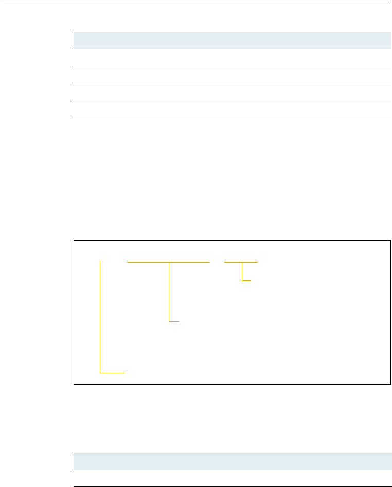
41.2 Satellite and SBAS DGPS mode
The AgGPS 332 receiver can receive L1/L2, LBand, Beacon, and RTK
signals. The Home screen indicates which mode the receiver is in for
differential correction.
Figure 4.7 explains the GPS status indicators that can appear on the
first line of the Home screen display.
Figure 4.7 GPS status
Table 4.1 explains the indicators that can appear in the Position Type
field.
Table 4.1 Position types
Display Description
SRCH Searching for satellites
TRCK Tracking satellites
G/2D Outputting 2-dimensional autonomous positions
G/3D Outputting 3-dimensional autonomous positions
D/2D Outputting 2-dimensional differential positions
D/3D Outputting 3-dimensional differential positions
x/3D Outputting unconverged OmniSTAR XP differential positions
X/3D Outputting converged OmniSTAR XP differential positions
D/3D í07 DOP03
Current PDOP value
Number of GPS satellites (SVs) being tracked
Position Type
AgGPS 332 GPS Receiver User Guide 41
Getting Started 4
Note – The “/” symbol in the position type spins when the receiver is
operating correctly.
Satellite DGPS mode status indicators
When the receiver is in Satellite mode, the second line of the Home
screen displays the status indicators shown in Figure 4.8.
Figure 4.8 Satellite DGPS mode status indicators
Table 4.2 shows the possible satellite differential mode indicators.
h/3D Outputting unconverged OmniSTAR HP differential positions
H/3D Outputting converged OmniSTAR HP differential positions
r/3D Outputting float RTK positions
R/3D Outputting fixed RTK positions
Table 4.2 Satellite differential mode status indicators
Indicator Description
S ####.### S/N ## Operating in Satellite Differential mode.
Table 4.1 Position types (continued)
Display Description
S 1556.2550 ÷ø10
Frequency for tracked DGPS satellite.
Available frequencies vary according to your
location and DGPS service provider.
Signal-to-noise ratio of
DGPS signal, see Table 4.3.
Receiver is using Satellite DGPS corrections.

4 Getting Started
42 AgGPS 332 GPS Receiver User Guide
Table 4.3 explains the signal-to-noise ratio values for both Satellite and
WAAS/EGNOS DGPS modes.
SBAS DGPS mode status indicators
When the receiver is in SBAS DGPS mode, the second line of the Home
screen displays the status indicators shown in Figure 4.9.
Figure 4.9 SBAS DGPS mode status indicators
S SRCH ###.## Searching for Satellite Differential signal.
S TRCK ####.## Tracking satellite without acquiring signal lock.
Table 4.3 Signal-to-noise values
Value Description
Below 4 Unusable
4–8 Fair
>8 Excellent
Table 4.2 Satellite differential mode status indicators
Indicator Description
WAAS 122 ÷ø07
Signal-to-noise ratio of DGPS signal,
see Table 4.3
WAAS satellite ID
Receiver is using WAAS/EGNOS corrections
AgGPS 332 GPS Receiver User Guide 43
Getting Started 4
41.3 Beacon DGPS mode
When in Beacon DGPS mode, the Home screen displays “B” (Beacon
DGPS) in the lower left corner. Figure 4.10 explains the status
indicators that appear on the first line of the Home screen display when
the receiver is in this mode.
Figure 4.10 Beacon DGPS status
Table 4.4 describes messages that can appear when the receiver is in
Beacon DGPS mode.
Table 4.4 Beacon DGPS operating mode messages
Message Description
B The receiver is operating in Beacon mode.
Beacon Searching The receiver is searching for beacon signals.
Beacon Tracking The receiver is tracking beacon signals and is attempting
to gain lock.
Beacon Idle Beacon DGPS is not active.
Beacon FFT The receiver is looking for a beacon across the signal
spectrum.
Beacon Disabled Beacon DGPS is disabled in the receiver. You will need to
change configuration settings to enable Beacon DGPS.
External RTCM Differential corrections are being provided by an external
source, through port A or port B.
B H – R 310.0 ÷ ø15
The beacon signal-to-noise
ratio. S/N values range from
0 to 30. High numbers are
best. Above 6 is acceptable.
The beacon frequency. Frequency varies
depending on the beacon used.
Indicates the receiver is using Beacon DGPS.
The beacon operating mode.

4 Getting Started
44 AgGPS 332 GPS Receiver User Guide
4.2 Updating the Firmware
To ensure that the receiver and office computer connect, when you are
ready to update the firmware, do one of the following:
•If you use a Windows CE or pocket PC device with the computer,
make sure that Microsoft ActiveSync® technology is disabled
from using the COM port on the computer.
•If you use a Palm Pilot with the computer, make sure that the
Palm Synchronization program is disabled from using the COM
port on the computer.
To update the receiver firmware when a new version is released:
1. Download the upgrade files.
2. Install the FlashLoader200 utility.
3. Connect the receiver to an office computer.
4. Upgrade the firmware from the office computer, using the
upgrade files.
For full details of how to do this, refer to the Release Notes provided
with your receiver firmware.
If you have problems when you update the firmware, see Chapter 6,
Troubleshooting. For further assistance, contact your local Trimble
reseller.

CHAPTER
5
AgGPS 332 GPS Receiver User Guide 45
Configuring the Receiver 5
In this chapter:
QIntroduction
QHome Screen
QConfiguring Differential GPS
QConfiguring the AgGPS Receiver to Operate in Beacon Mode
QConfiguring the AgGPS Receiver to Operate in RTK Mode
QConfiguring the Communication Ports
QDisplay Options
QInstalling Passcodes
5 Configuring the Receiver
46 AgGPS 332 GPS Receiver User Guide
5.1 Introduction
Use the LCD screen to change configuration settings in the AgGPS 332
receiver. You will need to configure the receiver if you connect to
another device, for example.
•If a Trimble AgGPS Autopilot system is configured to use an
AgGPS receiver, and the port on the receiver is set to 8-N-1,
38.4 K, the Autopilot system automatically configures the
receiver.
•The EZ-Guide Plus and EZ-Steer systems require that NMEA is
set to 8-N-1, 38.4K.
Note – OmniSTAR VBS, XP, and HP are subscriber services that need to be
activated. For more information, see OmniSTAR, page 47.
5.2 Home Screen
Figure 5.1 shows the AgGPS 332 Home screen when WAAS corrections
are being received.
Figure 5.1 AgGPS 332 Home screen
D/3D í07 DOP03
WAAS 122 ÷ø04
Correction type
DGPS satellite name or ID
Signal-to-noise ratio
of DGPS satellite
Current PDOP value
Position type
Number of GPS satellites being tracked
GPS indicators
Correction
indicators

AgGPS 332 GPS Receiver User Guide 47
Configuring the Receiver 5
5.3 Configuring Differential GPS
For the receiver to output GPS position coordinates of submeter
accuracy, you must first select a differential signal from one of the
following sources:
•SBAS (WAAS/EGNOS) – free service, limited availability
The Wide Area Augmentation System (WAAS) augments GPS
with additional signals for increasing the reliability, integrity,
accuracy, and availability of GPS in the United States. The
European Geostationary Navigation Overlay System (EGNOS) is
the European equivalent of WAAS.
•OmniSTAR – paid subscription, available worldwide
You can use this paid service as an alternative to WAAS/EGNOS.
It provides over-the-air DGPS activation.
For more information, see Differential GPS positioning (DGPS),
page 10.
53.1 OmniSTAR
The AgGPS 332 receiver can use OmniSTAR corrections. To do this, you
need to configure the receiver and purchase an OmniSTAR
subscription.
Note – To track the OmniSTAR satellite, the receiver must be outside with
a clear view of the sky, turned on, and configured to receive OmniSTAR
VBS or HP corrections.
To activate an OmniSTAR subscription:
1. From the Home screen, select Configuration / DGPS Config.
2. Set the Source Select field to one of the following:
–Omnistar HP
–Omnistar VBS
–Omnistar XP
5 Configuring the Receiver
48 AgGPS 332 GPS Receiver User Guide
3. Set the EZ Sat: Omni* field to the area you are operating in. For
example, if you are working in California, select N. America West.
4. Press 4 then 5 to complete the procedure.
5. Obtain an OmniSTAR licence from OmniSTAR. All licenses are
activated over the air. Contact OmniSTAR on 1-888-883-8476
(USA or Canada) and provide the following details:
– your billing information
– serial number
– satellite beam name
OmniSTAR will activate the receiver. Activation can take 5 to
30 minutes.
50.1 WAAS/EGNOS
WAAS is a free satellite-based DGPS service that is available only in
North America; EGNOS is a free satellite-based DGPS service that is
available only in Europe.
To use the WAAS/EGNOS DGPS signal, you must first configure the
receiver.
1. From the Home screen, select Configuration / DGPS Config.
2. Set the Source Select field to WAAS.
3. Press 4 then 5 to complete the procedure.
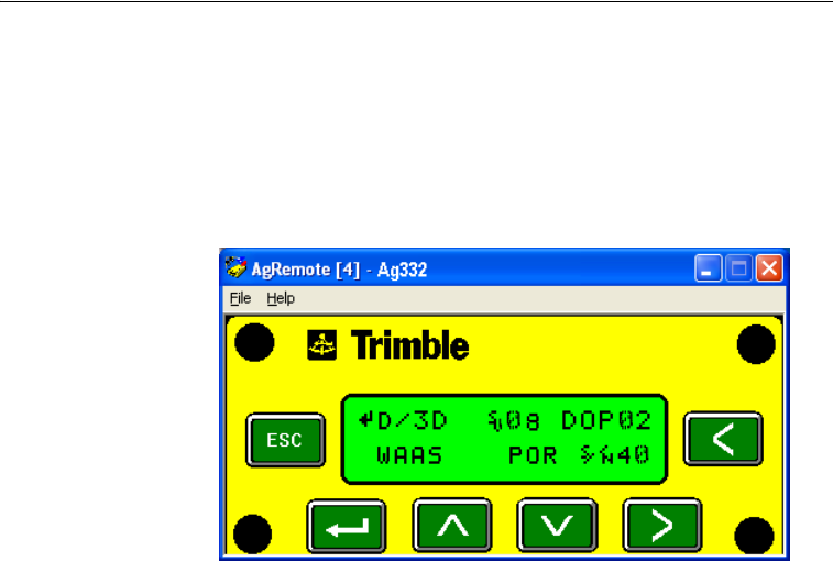
AgGPS 332 GPS Receiver User Guide 49
Configuring the Receiver 5
To enable WAAS reception in the field:
1. Take the receiver outside. Make sure that it has a clear southeast
and southwest view of the sky.
2. Turn on the receiver. WAAS activation can take two or more
minutes. Once activation succeeds, the Home screen displays
D/3D:
5.1 Configuring the AgGPS Receiver to Operate in
Beacon Mode
To configure the receiver in Beacon mode:
1. From the Home screen, select Configuration / DGPS Config.
2. Set the Source Select field to Beacon.
3. Press 4 then 5 to complete this part of the procedure.

5 Configuring the Receiver
50 AgGPS 332 GPS Receiver User Guide
5.1 Configuring the AgGPS Receiver to Operate in
RTK Mode
To configure the receiver in RTK mode:
1. From the Home screen, select Configuration / DGPS Config.
2. Set the Source Select field to RTK.
3. Press 4 then 5 to complete this part of the procedure.
4. For RTK operation, connect the radio to a port. Change the port
input settings for that port to RtkLnk.
5.1 Configuring the Communication Ports
If the receiver is to be connected to an external device, configure
Ports A and B so that the proper data type is input to and output from
the receiver.
To configure Port A:
1. From the Home screen, select Configuration / Port A Config.
2. Use the menu commands to configure the communication
ports. Ensure that the receiver outputs the correct GPS position
data type for the hardware device or software program that is
connected to the receiver.
To configure Port B:
•Repeat the above steps but in Step 1 select Configuration / Port B
Config.
To configure Port C:
•Repeat the above steps but in Step 1 select Configuration / Port C
Config.
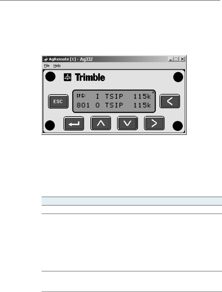
AgGPS 332 GPS Receiver User Guide 51
Configuring the Receiver 5
50.1 Configuring input/output communication
The port input and output settings appear in the first screen. In
Figure 5.2, the port is set to accept TSIP inputs at a baud rate of 115,000
with a parity of 8-Odd-1. The outputs are TSIP, also at a baud rate of
115,000.
Figure 5.2 Communication settings
To communicate with the AgGPS Autopilot, EZ-Guide Plus, or EZ-Steer
systems, or with external hardware devices and software programs,
configure the port input/output settings. Table 5.1 describes the input
settings.
Table 5.1 Port input settings
Setting Description
None Inputs nothing to the receiver.
TEXTB The receiver can accept ASCII data from an external device, such as
a chlorophyll meter, on Port A, merge it with NMEA GPS data, and
output the combined data on Port B. The incoming data must be
limited to 66 ASCII characters and terminated by a carriage return
and line feed (hex characters 0x0D 0x0A). The NMEA string
outputs as $PTNLAG001,<up to 66 ASCII characters>*<2 digit
checksum><CR><LF>. For the receiver to output the combined
NMEA string, NMEA must be selected as the output protocol on
Port B.
TEXTA See the description for the TEXTB setting (above). TEXTA input
outputs text on Port A. The default port settings are 8-N-1 TSIP
38.4 K. These may vary by product.

5 Configuring the Receiver
52 AgGPS 332 GPS Receiver User Guide
The default port settings are:
Note – If the receiver is to work with an Autopilot system, ensure that the
receiver port communication settings are 8-N-1 TSIP 38.4 K. To work with
some other devices and software programs, the receiver port
communication settings must be 8-N-1 NMEA 4800.
When using a Trimble SiteNet 900 radio, make sure that the
communication settings are correct in the receiver. The default settings
to use with the SiteNet radio are:
RTCM The receiver can accept RTCM data from an external DGPS device,
such as an external radio.
TSIP The receiver can accept or output TSIP data packets from the port
when using the AgGPS 170 Field Computer.
RtkLnk The receiver can accept real-time corrections (CMR data) from an
external device such as a Trimble radio.
Port A Port B
Baud rate In TSIP 38,400 TSIP 38,400
Out TSIP 38,400 TSIP 38,400
Data bits 8 8
Parity None None
Stop bits 1 1
Setting Description
Baud rate 38,400
Data bits 8
Parity None
Stop bits 1
Table 5.1 Port input settings (continued)
Setting Description

AgGPS 332 GPS Receiver User Guide 53
Configuring the Receiver 5
Changing the input or output port settings
1. From the Port A Config screen, press 2 until the Port-A
Input/Output screen appears.
2. Press 3 to activate the cursor.
3. Press 1 or 2 to change the value.
4. Press 3.
5. Repeat Step 3 through Step 4 until you have set all the required
values.
6. Press 4 to save all the changes.
7. Press 2 to move to the next screen.
NMEA settings
Three screens (NMEA1, NMEA2, and NMEA3) show what NMEA
messages are output from the port. Message types shown in upper case
are being output; message types shown in lower case are not.
For more information about NMEA message types, refer to the
document called NMEA-0183 Messages Guide for AgGPS Receivers on
the Trimble website (www.trimble.com).
Port output rate
This setting can be used to vary the NMEA and TSIP output rate. A
setting of 1 outputs one position each second.
ASAP equals the rate selected on the Position Rate screen under the
GPS Config menu. A setting of ASAP outputs positions five or ten times
every second. The default ( factory) setting is 1 Hz.
To change the receiver configuration settings, enter the Port Config
screens under the configuration menus.
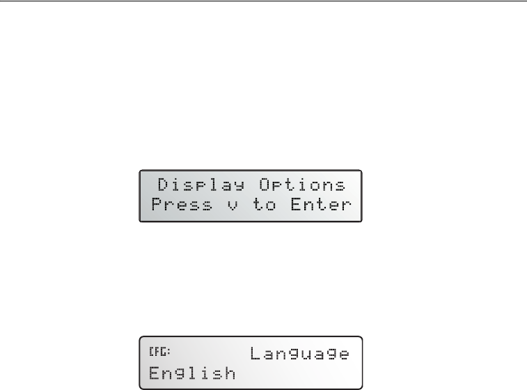
5 Configuring the Receiver
54 AgGPS 332 GPS Receiver User Guide
5.1 Display Options
Use the Display Options menu to control how information is displayed
in the screens that you can access from the Status and Configuration
menus.
To view the Display Options menu:
•From the Home screen, press 2:
Setting the language
To change the language displayed:
1. Navigate to the Language screen:
2. Press 3 to select the Language field.
3. Press 1 or 2 until the required language is displayed.
4. Press 4 to select it and save the changes.
5. Press 5 to return to the Display Options menu.
The screen automatically displays the selected language.
Setting the units
The Units screen displays U.S., Metric, or Nautical units in the screens
that you access from the Field Operation, Status, and Configuration
menus.
Note – This setting does not affect GPS position data output.
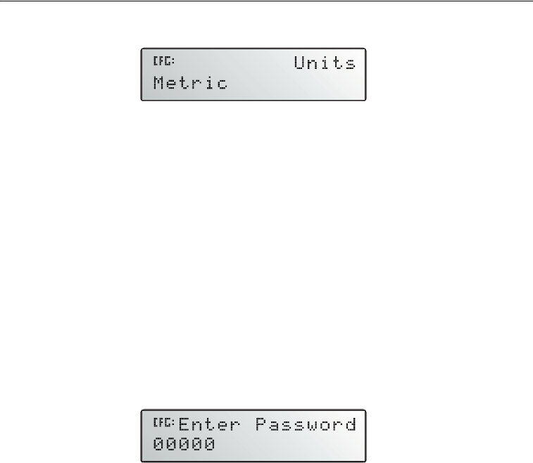
AgGPS 332 GPS Receiver User Guide 55
Configuring the Receiver 5
1. Navigate to the Units screen:
2. Press 3 to select the Units field.
3. Press 1 or 2 until the required unit is displayed.
4. Press 4 to select it and save the changes.
5. Press 5 to return to the Display Options menu.
6. Press 5 again to return to the Home screen.
Locking the Configuration menus
To prevent unauthorized changes to the configuration, you can lock the
Configuration menus:
1. Navigate to the Lock Display Cfg screen.
2. Press 4 to display the Enter Password screen. The cursor is
active on the first digit:
3. Use the last five numbers of the receiver serial number as the
password (“passcode”).
4. Press 1 or 2 until the first digit of the serial number appears.
5. Press 3 to select the next digit. Repeat step 3 until all five digits
are entered.
6. Press 4 to save the changes.
7. The Valid Password message appears, and the Configuration
menus are no longer displayed when you navigate the menus.
If the message Invalid Password appears, enter the password
again.

5 Configuring the Receiver
56 AgGPS 332 GPS Receiver User Guide
BTip – When the Configuration menus are locked, you can view most
Configuration menu settings from the Status menus.
To unlock the Configuration menus, repeat the above procedure.
Clearing battery-backed RAM
CWARNING – When you select the Clear BB Ram option, any changes that
you have made in the Configuration menus are deleted and cannot be
restored.
Use the Clear BB RAM screen to remove all configuration settings in the
receiver memory (RAM) and return the receiver to its factory default
configuration settings:
To delete battery-backed memory:
1. Navigate to the Clear BB RAM screen:
2. Press 3 to activate the cursor.
3. Press 1 or 2 to select Yes.
5.1 Installing Passcodes
When you purchase an option with your receiver, your Trimble Reseller
provides the necessary password. Once entered, the password is stored
in permanent memory and remains even when the receiver is switched
off.
Use the Update receiver screen of the AgGPS menu system to enter the
password directly into the receiver and activate the option for
immediate field use.
1. Navigate to the Update receiver screen. Press 4.
The active cursor highlights the first digit.
2. Press 1 or 2 to enter the first number of the password.

AgGPS 332 GPS Receiver User Guide 57
Configuring the Receiver 5
3. Press 3 to move to the next digit.
4. Repeat Step 2 through Step 3 until all numbers are entered.
5. Press 4 to save changes.
The screen displays the selected option as enabled.
If an error message appears, enter the password again. If you are still
unsuccessful, contact your local Trimble Reseller for assistance.
50.1 FlashLoader200 utility
If you have not yet done so, install the latest version of FlashLoader200
utility on the office computer. See page 44. Use FlashLoader200 to enter
one or more passwords:
1. On the office computer, click , then select Programs /
Flashloader200.
2. In the dialog that appears, select the Update receiver with
password check box. Click Proceed.
3. The Flash Progress dialog appears while the utility attempts to
find the receiver. When the receiver is found, the Enter
Passwords dialog appears.
If the receiver cannot be found, check that the cables are
properly connected and try again.
4. In the Enter Passwords dialog, enter the 10-digit password into
the first blank line. If you have more than one option, enter each
password on a separate line. Click OK.
The process takes a few seconds and a message appears when
completed.
5. In the dialog that appears, click Yes to continue.
6. When the successful operation message appears, click OK.
The option is successfully installed.

5 Configuring the Receiver
58 AgGPS 332 GPS Receiver User Guide
If any password operation fails, the FlashLoader200 utility displays a
message that identifies the failed option. Disconnect the receiver, then
reconnect it and try again. If you are still unsuccessful, contact your
local Trimble Reseller for assistance.


6 Troubleshooting
60 AgGPS 332 GPS Receiver User Guide
6.1 Introduction
This chapter describes some problems that can arise and explains how
to solve them. It includes a series of flowcharts to help with
troubleshooting.
As you work through this chapter, you may need to view the receiver
status or change values in some fields. For information on how to do
this, refer to the document called NMEA-0183 Messages Guide for
AgGPS Receivers. This document is on the Trimble website
(www.trimble.com).
6.2 Problems with GPS
Problem Possible solution
Poor accuracy
The accuracy of GPS positions is poor because
the receiver is picking up poor quality signals
from the satellites.
The receiver always calculates the most
accurate position it can, given the current GPS
satellite differential operating conditions.
Change some or all of the following GPS
settings:
•Minimum elevation – Increase the setting
(the default is 8°).
•Minimum Signal Strength – Increase the
System Mask AMU setting (the default is 3).
•Maximum PDOP – Decrease the setting
(the default is 13).
•GPS Mode – Change to Manual 3D
(the default is Auto 2D/3D).
•DGPS Mode – Change to DGPS
(the default is DGPS Auto/On/Off).
GPS signals are reflecting off nearby trees
and/or metal buildings and horizontal
surfaces.
To reduce multipath noise, mount the GPS
receiver so that it has a clear view of the sky.
The receiver must be away from trees and
large metal objects.
Intermittent loss of lock on satellite
The receiver loses the satellite signal from
time to time.
Make sure that the receiver is mounted on the
highest point of the vehicle and is clear of
metal surfaces.
Check Maximum PDOP and Minimum Signal
Strength settings (see Poor accuracy, above).

AgGPS 332 GPS Receiver User Guide 61
Troubleshooting 6
Intermittent DGPS signal
The correction signal strength can drop to
unusable levels. Causes include tree canopy
cover between the receiver and the
differential satellite, radar sets, and
microwave transmitters.
Move the receiver away from the tree cover
and/or from sources of electromagnetic
interference.
Tracking but not receiving a differential signal
The receiver is tracking satellites and tracking
an OmniSTAR satellite beam, but is not
receiving DGPS signals. The Home screen
indicates how many satellites are being
tracked, and whether a differential source is
being tracked.
You see:
h-3D for HP not converged
H-3D for HP converged
r-3D for RTK float
R-3D for RTK fixed
D-3D for DGPS
HP and RTK also give an indication of
positional accuracy on the Home screen.
Check that your DGPS service subscription is
still current and enabled.
For OmniSTAR service:
1. Use the AgRemote utility to navigate to
one of the following screens, depending on
what you are using:
•the Omni HP Info screen
•the Omni VBS Info screen.
2. Press 4 until Stop Date appears.
If the message Access Unknown appears,
contact OmniSTAR to reactivate your
subscription. For more information, see
OmniSTAR, page 47.
The receiver must be switched on and
configured to track the correct satellite
coverage beam before it can be reactivated.
The receiver automatically tracks the correct
beam based on receiver geographic location.
If the receiver is manually changed, automatic
tracking is deactivated until you perform a
hard reset or firmware flash.
When a satellite subscription is activated, the
Home screen displays D/3D.
Long time to initialize
In RTK mode, longer baselines require longer
initialization times. (The baseline is the
distance between the base receiver and the
rover receivers.)
Wait for the receiver to initialize or consider
repositioning the base receiver to shorten the
baseline. Make sure the rover is in a clear area.
Problem Possible solution

6 Troubleshooting
62 AgGPS 332 GPS Receiver User Guide
6.1 Interference Problems
Loss of initialization
In RTK mode initialization can be lost when
the rover receiver is close to trees or buildings
and the number of satellites falls below four.
Additionally, initialization may be lost if the
receiver has not been tracking RTK corrections
for some time. For more information, see the
next item.
Move away from trees and obstructions to
initialize. Once initialized, approach the
obstructed area again. If the obstructions are
severe, GPS positioning may not work in that
area.
Because the GPS satellites move, there may be
times of the day when you are working in an
area with obstructions. For more information,
see the Trimble Planning software on the
Trimble website (www.trimble.com).
Not tracking RTK corrections
The radio link is down or intermittent. •Ensure that the line-of-sight between the
base and rover receivers is not obstructed.
•Ensure that the rover receiver is within
range of the radio.
•Ensure that the radio power supply is on.
Problem Possible solution
Strong magnetic fields
Strong magnetic fields have no effect on GPS
or satellite DGPS signals.
However, some computers and other electric
equipment radiate electromagnetic energy
that can interfere with a GPS receiver.
If you suspect interference from a local
magnetic field, move the receiver away from,
or turn off, the suspect electronics while
observing the number of satellites being
tracked on the receiver or the signal-to-noise
ratio (SNR) of the satellite. If the SNR goes up
when the electronics are turned off, there may
be interference from the local electronics.
FM 2-way radios
Transmitting FM 2-way radios can interfere
with OmniSTAR, WAAS, and GPS signal
reception.
Make sure that there is at least 1 m (3 ft)
between the FM 2-way radio antenna and the
receiver.
Problem Possible solution

AgGPS 332 GPS Receiver User Guide 63
Troubleshooting 6
6.2 Problems with the GPS Receiver
Engine noise
An unshielded ignition system can cause
enough noise to block reception of a
differential signal.
Use resistor spark plug wires on the vehicle
ignition system.
An alternator can cause noise that interferes
with a differential signal.
•Use bypass capacitors, commonly available
in automotive stores for cleaning up
interference to CB and other radios. If the
problem persists, shield engine components
with aluminum foil.
•Relocate the antenna on the machine.
•Determine the optimal antenna location by
watching the SNR value on the Home
screen.
Note – Before replacing engine parts in an
attempt to solve this problem, make sure that
the problem is not caused by a computer or
power source near the receiver. Some
computers and their power sources cause
noise that disrupts GPS and satellite DGPS
signals.
Problem Possible solution
Mounting location
The receiver is not picking up a clear signal. Mount the receiver on the centerline of the
vehicle, away from any sources of interference
and with a clear view of the sky (see Choosing
a location, page 21).
Problem Possible solution

6 Troubleshooting
64 AgGPS 332 GPS Receiver User Guide
Cables
One of the cables seems faulty. Use an ohmmeter to check the cable. The
resistance of a good cable between connector
pins at each end of the cable is zero.
If the cable is sound, but the problem persists,
try exchanging the cable with one that you
know is working.
If the cable is defective, contact your local
Trimble Reseller for an RMA number (if the
Trimble product is still under warranty), or to
purchase a replacement cable.
Real-time clock battery
A lithium-ion battery in the receiver powers
the internal real-time clock and so enables the
receiver to get a first fix faster. The battery has
a life of 7.5 years. When the battery fails, the
internal clock cannot keep accurate time and
the receiver may take longer to output GPS
positions.
Please contact your local Trimble Reseller
to get the batteries replaced. You cannot
replace the battery yourself.
Factory defaults
You need to restore the receiver factory
defaults.
To restore receiver factory default settings:
1. Connect the receiver to a computer. Turn
on the receiver.
2. Run the AgRemote utility.
3. Navigate to the Clear BB RAM screen.
4. Press 2 until Yes appears.
5. Press 4.
The factory default settings are restored. The
DGPS service subscription is not lost.
Problem Possible solution

AgGPS 332 GPS Receiver User Guide 65
Troubleshooting 6
6.1 Problems with the FlashLoader200 Utility
Problem Possible solution
The FlashLoader 200 utility cannot detect the
receiver or download the firmware.
Make sure that:
•Other programs, such as Microsoft
ActiveSync technology, are not using the
COM port that the computer is using.
•The receiver is connected to a 12–32 V DC
power source.
•All cables are connected correctly between
the device and the computer.
•The receiver is connected to the correct
computer COM port. To do this:
1. From the FlashLoader200 menu, select
Settings.
2. Select the check box for a serial link.
3. At Port, select Auto. Click OK.
4. Select the Upload firmware to receiver
check box.
5. Navigate to where the firmware file is
saved and select the file. Click Proceed.
6. From the Auto Port Select dialog, select
Use receiver on port... and click OK.
Once you have checked this, turn off the
receiver then turn it on again. Try again to
connect the FlashLoader200 utility.

6 Troubleshooting
66 AgGPS 332 GPS Receiver User Guide


A Cables and Connectors
68 AgGPS 332 GPS Receiver User Guide
A.1 Introduction
This appendix contains pin-out information for standard and optional
cables. Use the information to troubleshoot communication problems
with the receiver and devices not supported by the standard and
optional cables.
A.2 Port A and Port B Connectors
Table A.1 gives pin-out requirements for the Port A, Port B, and Port C
connectors.
Table A.1 AgGPS 332 receiver Port A, Port B, and Port C
Pin Port A connector Port B connector Port C connector
1 Event In Event In Event In
2 RS-232 B Out RS-232 A Out
3 RS-232 B In RS-232 A In
4 CAN Hi CAN Hi CAN Hi
5 Ground Ground Ground
6 RTS Out RTS Out RTS Out
7 Power On/Off Power On/Off Power On/Off
8 CTS In CTS In CTS In
9 CAN Low CAN Low CAN Low
10 Battery +V Battery +V Battery +V
11 Battery –V Battery –V Battery –V
12 1 PPS Output 1 PPS Output 1 PPS Output

AgGPS 332 GPS Receiver User Guide 69
Cables and Connectors A
A.3 Standard Power/Data Cable
Table A.2 gives pin-out information for the standard power/data cable
(P/N 30945).
Table A.2 Standard power/data cable
To re ce i ve r
P1 connector
12-pin (female)
7 cond
cable
To c o m p u t er
P2 connector
DE9 (female)
To DC p o w er
2 conductor
cable
Pin Signal Color Pin Signal Color Signal
1Event In ← Black 4 DTR
2TXD → Orange 2 RXD
3RXD ← Red 3 TXD
4
5 SIG GND ↔ Shield 5 SIG GND
6RTS → Yellow 8 RTS
8CTS ← Green 7 CTS
9
71
1Pins 7 and 10 of the P1 connector are jumpered with a 5 kOhm, 5% resistor.
PWR ON ←
101V+ IN ← Red Red V+ IN
11 V– IN ← Black Black V– OUT
12 PPS →Blue 9 PPS

A Cables and Connectors
70 AgGPS 332 GPS Receiver User Guide

APPENDIX
B
AgGPS 332 GPS Receiver User Guide 71
Specifications B
In this appendix:
QIntroduction
QAgGPS 332 Receiver Physical Characteristics
QGPS Channels Performance
QL-Band Satellite Differential Correction Receiver with OmniSTAR
Support
QReceiver Default Settings
QDGPS Antenna
QDual-Frequency Antenna
QBeacon Channels

B Specifications
72 AgGPS 332 GPS Receiver User Guide
B.1 Introduction
This appendix details specifications for the AgGPS 332 receiver and the
compatable Trimble antennas.
B.2 AgGPS 332 Receiver Physical Characteristics
B.3 GPS Channels Performance
Item Description
Size 14.78 cm wide x 5.58 cm high x 21.59 cm deep
(5.70 in x 2.20 in x 8.60 in)
Power Nominal 350 mA at 12 V DC
Operating temperature –30 °C (–22 °F) through +70 °C (+158 °F)
Storage temperature –40 °C (–40 °F) through +85 °C (+185 °F)
Humidity Complies with Mil 810E Method 507.3 Procedure III Aggravated
Cyclic Humidity.
Ten 24 hour cycles of constant 95% RH, with cycling temperature
and dwells +30 °C (+86 °F) and +60 °C (140 °F). Unit sealed to +/-
5PSID
Casing Low-profile UV-resistant plastic. Dust-proof, waterproof, shock
resistant, with recessed protected connectors.
Connectors 12-pin Deutsch connectors
Ports Two connection ports, both of which support RS-232 and CAN
Mounting Three holes for 10 mm (0.39 in) bolts
Compliance FCC Part 15 Class A, C-Tick, E-mark, CE-mark
Item Description
General 12-channel, parallel tracking L1 1571.42 MHz and L2
1227.60 MHz. C/A code and carrier phase filtered measurement.
Update rate 1, 5, 10 Hz
RTK speed accuracy 0.16 kph (0.10 mph)

AgGPS 332 GPS Receiver User Guide 73
Specifications B
RTK position accuracy Horizontal 2.5cm (0.98in) + 2ppm, 2sigma, and vertical
3.7 cm (1.46 in) + 2 ppm, 2 sigma, if all of the following
criteria are met:
•At least 5 satellites
•PDOP <4
•CMR corrections
•Standard format broadcast from a Trimble MS750, AgGPS
214, or equivalent reference station
Differential speed accuracy 0.16 kph (0.1 mph)
Differential position accuracy Less than 1 m (3.28 ft) horizontal if all of the following criteria
are met:
•At least 5 satellites
•PDOP <4
•RTCM SC-104 corrections
•Standard format broadcast from a Trimble MS750, AgGPS
214, or equivalent reference station
OmniSTAR HP speed accuracy 0.16 kph (0.1 mph)
OmniSTAR HP position
accuracy
10 cm (3.94 in) after convergence, 2 sigma, if all the
following criteria are met:
•At least 5 satellites
•PDOP <4
•OmniSTAR HP corrections
Convergence time can vary, depending on the environment.
Time to the first fix (submeter accuracy) is typically <30 seconds;
time to the first useable fix (<10 cm accuracy) is typically
<30 minutes.
OmniSTAR XP position
accuracy
20 cm (7.87 in) after convergence, 2 sigma, if all the
following criteria are met:
•At least 5 satellites
•PDOP <4
•OmniSTAR XP corrections
Convergence time can vary, depending on the environment.
Time to the first fix (submeter accuracy) is typically <30 seconds;
time to the first useable fix (<10 cm accuracy) is typically
<30 minutes
Time to first fix <30 seconds, typical
Multipath mitigation EVEREST technology
Item Description

B Specifications
74 AgGPS 332 GPS Receiver User Guide
B.4 L-Band Satellite Differential Correction
Receiver with OmniSTAR Support
B.5 Receiver Default Settings
Satellite differential
compatibility
OmniSTAR, WAAS, and EGNOS
NMEA messages GGA 1 11, GLL, GSA1, GST, GSV, GST, MSS, PTNLDG, PTNL PJK,
PTNL PJT, PTNL VGK, PTNL VHD, PTNLEV, PTNLID, PTNLSM, RMC1,
VGK, VTG1, XTE, ZDA
1 By default, the receiver is configured to output GCA, GSA, RMC, and VTG messages at a 1 Hz
(1 position per second) update rate.
Item Description
Bit error rate 10-5 for Eb/N of >5.5 dB
Acquisition and reacquisition time <5 seconds, typical
Frequency band 1525–1559 MHz
Channel spacing 0.5 kHz
Item Description
DGPS source WAAS/EGNOS
Dynamics Land
Minimum elevation 8°
AMU mask 3
PDOP mask 13
PDOP 2D/3D switch 11
DGPS mode Auto On/Off
DGPS correction age limit 250 seconds
Pos fix rate 1 Hz
Item Description

AgGPS 332 GPS Receiver User Guide 75
Specifications B
B.6 DGPS Antenna
B.7 Dual-Frequency Antenna
B.8 Beacon Channels
Item Description
Size 15.5 cm D x 14.0 cm H (6.1 in x 5.5 in)
Weight 0.55 Kg (1.2 lb)
Operating temperature –30°C to +65°C
Storage temperature –40°C to +80°C
Humidity 100% condensing, unit fully sealed
Casing Dust-proof, waterproof, shock resistant
Item Description
Size 16 cm D x 7.5 cm H x (6.25 in x 3 in H)
Weight 0.55 Kg (1.2 lb)
Operating temperature –30°C to +65°C
Storage temperature –40°C to +80°C
Humidity 100% condensing, unit fully sealed
Casing Dust-proof, waterproof, shock resistant
Item Description
Frequency range 283.5 kHz to 325.0 kHz
Channel Spacing 500 Hz
Beacon modulation 50, 100, and 200 bits/second
Signal strength 10 mV/meter minimum
Dynamic range 100 dB
Channel selectivity 70 dB @ > 500 Hz offset
Frequency offset 17 ppm maximum
3rd order intercept +15 dBm @ RF input (min. AGC setting)
Beacon acquisition time <5 seconds, typical
Operating modes Auto Power, Auto Range, and Manual

B Specifications
76 AgGPS 332 GPS Receiver User Guide

APPENDIX
C
AgGPS 332 GPS Receiver User Guide 77
NMEA-0183 Messages C
In this appendix:
QIntroduction
QNMEA-0183 Message Structure
QNMEA Message Summary
QGGA (GPS Fix Data)
QGLL (Position Data)
QGRS (GPS Range Residuals)
QGSA (GPS DOP and Active Satellites)
QGST (GPS PRN)
QGSV (GPS Satellites in View)
QMSS (Beacon Receiver Signal Status)
QRMC (Recommended Minimum Specific GPS Data)
QVTG (Course Over Ground and Ground Speed)
QXTE (Cross-Track Error)
QZDA (Time and Date)
QPTNLEV Proprietary (Event Marker)
QPTNLID Proprietary (Trimble Receiver ID)
QPTNLDG Proprietary (Trimble DGPS Receiver Status)
QPTNL,GGK (Time, Position, Position Type, and DOP)
QPTNLSM Proprietary (RTCM Special)
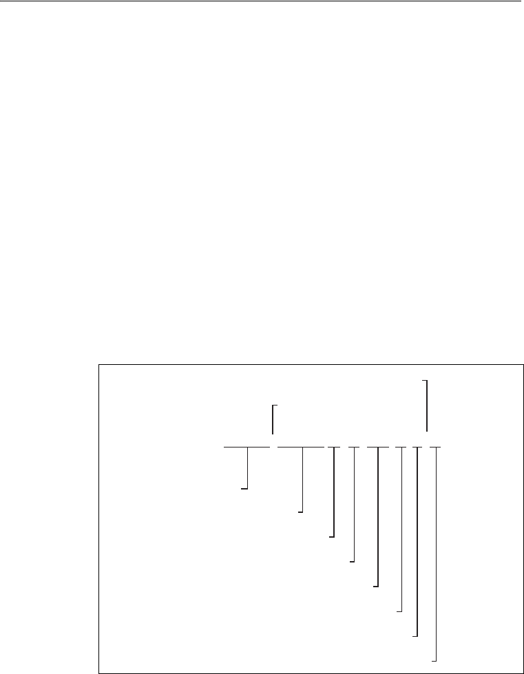
C NMEA-0183 Messages
78 AgGPS 332 GPS Receiver User Guide
C.1 Introduction
Trimble AgGPS receivers output NMEA (National Marine Electronic
Association) messages for GPS position data transfer between
electronics equipment. Information on the NMEA-0183
communication standard for GPS receivers is available at
www.nmea.org.
This appendix describes NMEA-0183 standard messages that are
configured using TSIP command packets.
Other messages are supported only when specific Trimble options are
installed on the receiver. Messages beginning with PTNL are Trimble
proprietary messages.
C.2 NMEA-0183 Message Structure
NMEA-0183 messages are strings of comma-delimited text. Figure C.1
shows the structure of an NMEA-0183 message.
Figure C.1 Example showing NMEA-0183 message structure — ZDA
$GPZDA,
220320.0, 26, 06, 2004, -5, 15 *52
Checksum
Sentence ID
Field 1
Field 2
Field 3
Field 4
Field 5
Comma Delimiter
Field 6
Asterisk Delimiter

AgGPS 332 GPS Receiver User Guide 79
NMEA-0183 Messages C
Each NMEA message includes:
•an identifier to distinguish it from other messages in the data
stream
•one or more fields of data, separated by a comma
•a checksum (preceded by *) to validate the data
Table C.1 explains the fields in the ZDA example shown in Figure C.1.
Fields 5 and 6 together give the total offset. Local time is 5 hours and
15 minutes earlier than GMT.
C2.1 Symbols and delimiters
All messages follow the NMEA-0183 Version 2.1 format, in which
symbols and delimiters identify or separate the message data.
NMEA-0183 messages always:
•begin with a dollar sign ($) followed by a talker ID code ( for
example GP) and a message ID code ( for example, ZDA)
•end with a carriage return and line feed
Table C.1 Fields in an NMEA-0183 message — ZDA
Field Data Description
1 220320.0 Time in UTC
2 26 Day (01 to 31)
3 06 Month (01 to 12)
41997 Year
5 -5 Local time zone offset from GMT
(in hours 00 to ±13 hours)
6 15 Local time zone offset from GMT (in minutes)

C NMEA-0183 Messages
80 AgGPS 332 GPS Receiver User Guide
C2.2 Checksum values
Newer Trimble receivers conform to the NMEA-0183 Version 2.1 format,
in which checksums are mandatory for all messages.
The checksum is calculated from all characters in the message,
including commas but excluding the “$” and “*” delimiters. The
hexadecimal result is converted to two ASCII characters (0–9, A–F), of
which the most significant appears first.
C2.3 Field formats
The data values output by Trimble AgGPS receivers meet the
NMEA-0183 Version 2.1 standard.
C2.4 Null fields
If a message contains a fixed number of fields, null (empty) fields are
included if no data is available. These fields are usually reserved for
data that is transmitted on a periodic or irregular basis.
C2.5 Talker ID codes
Talker ID code identifies the source of the data ( for example, GPS,
Loran C, or Sounder). Table C.2 describes the Talker ID codes that are
available for NMEA-0183 output from most Trimble receivers.
Table C.2 Supported Talker ID codes
Code Description
GP GPS
LG Loran C/ GPS
LC Loran C
II Integrated Instrumentation

AgGPS 332 GPS Receiver User Guide 81
NMEA-0183 Messages C
C2.6 Latitude and longitude values
The latitude and longitude values in NMEA-0183 messages are
presented in degrees, minutes, and decimal minutes, in a single field:
•latitude (ddmm.mmmm)
•longitude (dddmm.mmmm)
Latitude and longitude direction values are sent in a separate field as N,
S, E, or W.
C2.7 Time values
Time values in Universal Time Coordinated (UTC) are presented in
hhmmss.ss format, where hh is hours (00–23), mm is minutes, and ss.ss
is seconds and fractions of seconds.
C2.8 Reading NMEA string format
Be aware that NMEA strings can be of varying length, depending on
how the receiver is configured. Comma delimited parsing is
recommended.

C NMEA-0183 Messages
82 AgGPS 332 GPS Receiver User Guide
C.3 NMEA Message Summary
Table C.3 describes the NMEA-0183 message set that is supported by
the AgGPS receivers.
Note – Some messages are only supported when specific Trimble options
are installed on the receiver.
Messages beginning with PTNL are Trimble proprietary messages.
Table C.3 NMEA message summary
Message Message Contents
GGA (GPS Fix Data) Time, position, and fix related data
GLL (Position Data) Position fix, time of position fix, and status
GRS (GPS Range
Residuals)
GPS range residuals
GSA (GPS DOP and Active
Satellites)
GPS position fix mode, SVs used for navigation and DOP values
GST (GPS PRN) GPS Pseudorange Noise (PRN) statistics
GSV (GPS Satellites in
View)
Number of SVs visible, PRN numbers, elevation, azimuth and SNR
values
MSS (Beacon Receiver
Signal Status)
Signal strength, signal-to-noise ratio, beacon frequency, and
beacon bit rate
RMC (Recommended
Minimum Specific GPS
Data)
UTC time, status, latitude, longitude, speed over ground (SOG),
date, and magnetic variation of the position fix
VTG (Course Over
Ground and Ground
Speed)
Actual track made good and speed over ground
XTE (Cross-Track Error) Cross-track error
ZDA (Time and Date) UTC time, day, month, and year, local zone number and local zone
minutes
PTNLDG Proprietary
(Trimble DGPS Receiver
Status)
Beacon channel strength, channel SNR, channel frequency, channel
bit rate, channel number, channel tracking status, RTCM source,
and channel performance indicator
PTNLEV Proprietary
(Event Marker)
Time, event number, and event line state for time-tagging change
of state on an event input line

AgGPS 332 GPS Receiver User Guide 83
NMEA-0183 Messages C
All messages in this appendix are presented in the format shown in
Table C.1. In each example, the structure is shown in the paragraph
before the table.
PTNL,GGK (Time,
Position, Position Type,
and DOP)
Time, Position, Position Type and DOP values
PTNLID Proprietary
(Trimble Receiver ID)
Receiver machine ID, product ID, major and minor release numbers,
and firmware release date
PTNLSM Proprietary
(RTCM Special)
Reference Station Number ID and the contents of the Special
Message included in valid RTCM Type 16 records
Table C.3 NMEA message summary (continued)
Message Message Contents

C NMEA-0183 Messages
84 AgGPS 332 GPS Receiver User Guide
C.4 GGA (GPS Fix Data)
The GGA message contains the time, position, and fix related data.
The GGA message structure is:
$GPGGA,151924,3723.454444,N,12202.269777,
W,2,09,1.9,–17.49,M,–25.67,M,1,0000*57
Table C.4 describes these fields.
Table C.4 GGA message fields
Field Description
1 UTC of position fix in HHMMSS.SS format
2 Latitude in DD MM,MMMM format (0-7 decimal places)
3 Direction of latitude
N: North
S: South
4 Longitude in DDD MM,MMMM format (0-7 decimal places)
5 Direction of longitude
E: East
W: West
6GPS Quality indicator
0: fix not valid
1: GPS fix
2: DGPS fix
7 Number of SVs in use, 00-12
8 HDOP
9 Antenna height, MSL reference
10 “M” indicates that the altitude is in meters
11 Geoidal separation
12 “M” indicates that the geoidal separation is in meters
13 Age of differential GPS data record, Type 1; Null when DGPS not used
14 Base station ID, 0000-1023

AgGPS 332 GPS Receiver User Guide 85
NMEA-0183 Messages C
C.5 GLL (Position Data)
The GLL message specifies the position fix, time of position fix, and
status.
The GLL message structure is:
$GPGLL,3723.4543,N,12202.2696,W,151933,
A*3E
Table C.5 describes these fields.
Table C.5 GLL message fields
Field Description
1 Latitude in dd mm,mmmm format (0-7 decimal places)
2 Direction of latitude
3 Longitude in ddd mm,mmmm format (0-7 decimal places)
4 Direction of longitude
5 UTC of position in hhmmss.ss format
6 Fixed text “A” shows that data is valid

C NMEA-0183 Messages
86 AgGPS 332 GPS Receiver User Guide
C.6 GRS (GPS Range Residuals)
The GRS message is used to support the Receiver Autonomous
Integrity Monitoring (RAIM).
The GRS message structure is:
$GPGRS,220320.0,0,-0.8,-0.2,-0.1,
-0.2,0.8,0.6,,,,,,,*55
Table C.6 describes these fields.
Note – Because the contents of this NMEA message do not change
significantly during a one-second interval, the receiver outputs this
message at a maximum rate of 1 Hz.
Table C.6 GRS message fields
Field Description
1 UTC time of GGA position fix
2Residuals
Residuals used to calculate position given in the matching
GGA line
1: Residuals recomputed after the GGA position was computed
3-14 Range residuals for satellites used in the navigation solution, in
meters

AgGPS 332 GPS Receiver User Guide 87
NMEA-0183 Messages C
C.7 GSA (GPS DOP and Active Satellites)
The GSA message identifies the GPS position fix mode, the SVs used for
navigation, and the Dilution of Precision values.
The GSA message structure is:
$GPGSA,A,3,19,28,14,18,27,22,31,29,,,,,
1.7,1.0,1.3*35
Table C.7 describes these fields.
Table C.7 GSA message fields
Field Description
1Mode
M: Manual, forced to operate in 2D or 3D
A: Automatic, 3D/2D
2Mode
1: Fix not available
2: 2D
3: 3D
3–14 IDs of SVs used in position fix (null for unused fields)
15 PDOP
16 HDOP
17 VDOP

C NMEA-0183 Messages
88 AgGPS 332 GPS Receiver User Guide
C.8 GST (GPS PRN)
The GST message is used to support Receiver Autonomous Integrity
Monitoring (RAIM).
The GST message structure is:
$GPGST,220320.0,1.3,0.8,0.5,166.1,0.8,0.5,1.6,*4F
Table C.8 describes these fields.
Note – Because the contents of this NMEA message do not change
significantly during a one-second interval, the receiver outputs this
message at a maximum rate of 1 Hz.
Table C.8 GST message fields
Field Description
1UTC time of GGA fix
2RMS value of the standard deviation of the range inputs to the
navigation process (range inputs include pseudoranges and DGPS
corrections)
3 Standard deviation of semi-major axis of error ellipse, in meters
4 Standard deviation of semi-minor axis of error ellipse, in meters
5 Orientation of semi-major axis of error ellipse, in degrees from true
north
6 Standard deviation of latitude error, in meters
7 Standard deviation of longitude error, in meters
8 Standard deviation of altitude error, in meters

AgGPS 332 GPS Receiver User Guide 89
NMEA-0183 Messages C
C.9 GSV (GPS Satellites in View)
The GSV message identifies the number of SVs in view, the PRN
numbers, elevation, azimuth and SNR values.
The GSV message structure is:
$GPGSV,4,1,13,02,02,213,,03,
-3,000,,11,00,121,,14,13,172,05*67
Table C.9 describes these fields.
Note – Because the contents of this NMEA message do not change
significantly during a one-second interval, the receiver outputs this
message at a maximum rate of 1 Hz.
Table C.9 GSV message fields
Field Description
1 Total number of messages of this type in this cycle
2 Message number
3 Total number of SVs visible
4 SV PRN number
5 Elevation in degrees, 900 maximum
6 Azimuth, degrees from true north, 0000 to 3590
7 SNR, 00-99 dB (null when not tracking)
8–11 Information about second SV, same format as fields 4–7
12–15 Information about third SV, same format as fields 4–7
16–19 Information about fourth SV, same format as fields 4–7

C NMEA-0183 Messages
90 AgGPS 332 GPS Receiver User Guide
C.10MSS (Beacon Receiver Signal Status)
The MSS message identifies the status of the beacon signal, including
the beacon signal strength, beacon signal-to-noise ratio (SNR), beacon
frequency, and beacon bit rate.
The MSS message structure is:
$GPMSS,52.5,23.7,287.0,100*4C
Table C.10 describes these fields.
Note – Because the contents of this NMEA message do not change
significantly during a one-second interval, the receiver outputs this
message at a maximum rate of 1 Hz.
Table C.10 MSS message fields
Field Description
1 Signal strength (SS), dB ref: 1 υV/m
2 Signal-to-Noise Ratio (SNR), dB
3 Beacon frequency, 283.5–325.0 kHz
4 Beacon bit rate (25, 50, 100, 200), bits per second
5 Channel number

AgGPS 332 GPS Receiver User Guide 91
NMEA-0183 Messages C
C.11RMC (Recommended Minimum Specific GPS
Data)
The RMC message identifies the UTC time, status, latitude, longitude,
speed over ground (SOG), date, and magnetic variation of the position
fix.
The RMC message structure is:
$GPRMC,184804.00,A,3723.476543,N,
12202.239745,W,000.0,0.0,051196,15.6,E*7C
Table C.11 describes these fields.
Table C.11 RMC message fields
Field Description
1 Time: UTC time of the position fix in hhmmss.ss format
2 Status
Valid
V: Navigation Receiver Warning (V is output whenever the
receiver suspects something is wrong)
3 Latitude coordinate (the number of decimal places, 0–7, is
programmable and determined by the numeric precision selected
in TSIP Talker for a RMC message)
4 Latitude direction
N = North, S = South
5 Longitude coordinate (the number of decimal places, 0–7, is
programmable and determined by the numeric precision selected
in TSIP Talker for a RMC message)
6 Longitude direction
W: West
E: East
7 Speed Over Ground (SOG) in knots (0–3 decimal places)
8 Track Made Good, True, in degrees
9 Date in dd/mm/yy format
10 Magnetic Variation in degrees

C NMEA-0183 Messages
92 AgGPS 332 GPS Receiver User Guide
11 Direction of magnetic variation
E: Easterly variation from True course (subtracts from True
course)
W: Westerly variation from True course (adds to True course)
12 Mode indication
A: Autonomous
D: Differential
N: Data not valid
Table C.11 RMC message fields (continued)
Field Description

AgGPS 332 GPS Receiver User Guide 93
NMEA-0183 Messages C
C.12VTG (Course Over Ground and Ground Speed)
The VTG (Velocity True Ground) message identifies the actual track
made good and speed over ground.
The VTG message structure is:
$GPVTG,0,T,,,0.00,N,0.00,K*33
Table C.12 describes these fields.
Note – Because the contents of this NMEA message do not change
significantly during a one-second interval, the receiver outputs this
message at a maximum rate of 1 Hz.
Table C.12 VTG message fields
Field Description
1 Track made good
2 Fixed text “T” shows that track made good is relative to true north
3 Not used
4 Not used
5 Speed over ground in knots (0–3 decimal places)
6 Fixed text “N” shows that speed over ground is in knots
7 Speed over ground in kilometers/hour (0–3 decimal places)
8 Fixed text “K” shows that speed over ground is in kilometers/hour

C NMEA-0183 Messages
94 AgGPS 332 GPS Receiver User Guide
C.13XTE (Cross-Track Error)
The XTE message reports the vessel’s cross-track error.
The XTE message structure is :
$GPXTE,A,A,0.050,L,N*5E
Table C.13 describes these fields.
Table C.13 XTE message fields
Field Description
1
2
3 Cross-track error, in nautical miles
4 Direction to steer
L: Left
R: Right
5N: Nautical mile units

AgGPS 332 GPS Receiver User Guide 95
NMEA-0183 Messages C
C.14ZDA (Time and Date)
The ZDA message identifies UTC time, day, month, and year, local zone
number and local zone minutes.
The ZDA message structure is:
$GPZDA,184830.15,05,11,1996,00,00*66
Table C.14 describes these fields.
Note – Because the contents of this NMEA message do not change
significantly during a one-second interval, the receiver outputs this
message at a maximum rate of 1 Hz.
Table C.14 ZDA message fields
Field Description
1UTC time
2Day
3Month
4 Year
5 Local zone number (– for East Longitude)
6 Local zone minutes
C NMEA-0183 Messages
96 AgGPS 332 GPS Receiver User Guide
C.15PTNLEV Proprietary (Event Marker)
The PTNLEV message is a Trimble proprietary message for
time-tagging and marking when an event input occurs. If enabled, this
event message is output whenever an event is detected.
The PTNLEV message structure is:
$PTNLEV,184804.00,0*XX
Table C.15 describes these fields.
Table C.15 PTNLEV message fields
Field Description
1 Time: UTC time of the position fix in hhmmss.ss format
2 Event number, starting with event 0

AgGPS 332 GPS Receiver User Guide 97
NMEA-0183 Messages C
C.16PTNLID Proprietary (Trimble Receiver ID)
The PTNLID message is a Trimble proprietary message for identifying
the receiver’s machine ID, product ID, major and minor release
numbers, and firmware release date.
The PTNLID message structure is:
$PTNLID,097,01,XXX,XXX,DD/MM/YY*XX
Table C.16 describes these fields.
The PTNLID message, if enabled, is output every 30 seconds.
Table C.16 PTNLID message fields
Field Description
1 Machine ID
2 Product ID
3 Major firmware release number
4 Minor firmware release number
5 Firmware release date, in dd/mm/yy format

C NMEA-0183 Messages
98 AgGPS 332 GPS Receiver User Guide
C.17PTNLDG Proprietary (Trimble DGPS Receiver
Status)
The PTNLDG message is a Trimble proprietary message for identifying
the DGPS receiver channel strength, channel SNR, channel frequency,
channel bit rate, channel number, channel tracking status, RTCM
source, and channel performance indicator for either beacon DGPS or
satellite DGPS.
The PTNLDG message structure is:
$PTNLDG,87.0,5.2,1558510.0,1200,2,4,1,25,,,*01
Table C.17 describes these fields.
Table C.17 PTNLDG message fields
Field Description
1 Channel signal strength, in 1 dBuV/m. For beacon, this is the
electromagnetic field intensity level. For satellite, this is the ADC
input voltage level.
2 Channel signal to noise (SNR) level, in dB
3 Channel frequency, in kHz
4 Channel bit rate, in bits per second (bps)
5 Channel number, 0–99
6 Channel tracking status
0: Channel idle
1: Wideband FFT search
2: Searching for signal
3: Channel has acquired signal
4: Channel has locked on signal
5: Channel disabled
7 Specified channel is used as RTCM source
0: Not used
1: Used
8 Channel tracking performance indicator. For beacon, this is the
number of errors in the last 255 words. For satellite, this is the time
since last sync, in tenths of seconds ranging from 0–255.

AgGPS 332 GPS Receiver User Guide 99
NMEA-0183 Messages C
The PTNLDG message fields are defined in free format.
The maximum number of characters in each field is indicated above
( for example, 25 bps displayed as xxx,25,xxx instead of xxx,00025,xxx).
If a channel is disabled, the channel fields can be null fields (showing
commas only). If more than one channel is available, the message
should be repeated for each channel.
This message can be enabled using TSIP. If enabled, it is output at the
NMEA report rate.
Note – Because the contents of this NMEA message do not change
significantly during a one-second interval, the receiver outputs this
message at a maximum rate of 1 Hz.

C NMEA-0183 Messages
100 AgGPS 332 GPS Receiver User Guide
C.18PTNL,GGK (Time, Position, Position Type, and
DOP)
The PTNL,GGK message structure is:
$PTNL,GGK,172814.00,071296,3723.46587704,
N,12202.26957864,W,3,06,1.7,EHT-6.777,M*48
Table C.18 describes these fields.
Table C.18 PTNL,GGK message fields
Field Description
1 UTC of position fix, in hhmmss.ss format
2 UTC Date of position, in mmddyy format
3 Latitude, in degrees and decimal minutes (for example,
dddmm.mmmmmmm)
4 Direction of latitude
N: North
S: South
5 Longitude, in degrees and decimal minutes (for example,
dddmm.mmmmmmm)
6 Direction of longitude
E: East
W: West
7 GPS quality indicator
0: Fix not available or invalid
1: Autonomous GPS fix
4: Differential, code phase only solution (DGPS)
8 Number of satellites used in GPS solution
9DOP of fix
10 Ellipsoidal height of fix (antenna height above ellipsoid)
11 M: Ellipsoidal height is measured in meters

AgGPS 332 GPS Receiver User Guide 101
NMEA-0183 Messages C
C.19PTNLSM Proprietary (RTCM Special)
The PTNLSM message is a Trimble proprietary message for identifying
the Reference Station ID and the ASCII Text message that is included in
an RTCM Type 16 Special Message. The PTNLSM message is generated
anytime an RTCM stream receives a valid Type 16 Special Message.
The PTNLSM message structure is:
$PTNLSM,0022,This is a message,*.XX
Table C.19 describes these fields.
Table C.19 PTNLSM message fields
Field Description
1 Reference station ID number, ranging from 0 to 1023. Leading
zeros must be added to fill four-digit field.
2 ASCII text message contained within the Type 16 RTCM message.

C NMEA-0183 Messages
102 AgGPS 332 GPS Receiver User Guide


D Third-Party Interface Requirements
104 AgGPS 332 GPS Receiver User Guide
D.1 Software
The following table lists the interface requirements for connecting an
AgGPS receiver to third-party software.
Software Company Protocol NMEA
messages
Baud
rate
Other Pos Rate Cable P/N
required
Notes
AgGPS
EZ-Map Trimble NMEA GGA 38.4K 8-N-1 5Hz 30945,
40947-18,
46441
Do not output ZDA
message.
AgView GIS
Solutions NMEA VTG, GLL 4800 8-N-1 1Hz 30945,
40947-18,
46441
FarmGPS Red Hen NMEA GGA, GSA,
VTG 4800 8-N-1 1 Hz 30945,
40947-18,
46441
Field Rover SST Dev
Group NMEA GGA, GSA,
GSV, VTG 4800 8-N-1 1 Hz 30945,
40947-18,
46441
Do not output MSS
message.
Field
Worker Pro Field
Worker NMEA GGA, GLL,
RMC, VTG 4800,
9600 8-N-1 1 Hz 30945,
40947-18,
46441
FieldLink
DOS Agris NMEA GGA, GSA,
VTG 4800,9
600 8-N-1 1 Hz 30945,
40947-18,
46441
FieldLink
Windows Agris NMEA GGA, GSA,
VTG 4800,
9600 8-N-1 1 Hz 30945,
40947-18,
46441
GuideMate Raven/Far
mworks NMEA GGA, VTG 19.2K 8-N-1 1 Hz, 5 Hz 30945,
40947-18,
46441
HGIS Starpal NMEA GGA, RMC 4800,
9600 8-N-1 1 Hz 30945,
40947-18,
46441
Instant
Survey AgriLogic
(Case-IH) NMEA GGA, GSA,
RMC 4800 8-N-1 1 Hz 30945,
40947-18,
46441
Pocket
Survey AgriLogic
(Case-IH) NMEA GGA, GSA,
RMC 4800 8-N-1 1 Hz 30945,
40947-18,
46441
SiteMate Farmworks NMEA GGA, VTG 4800 8-N-1 1 Hz 30945,
40947-18,
46441
SST Stratus SST Dev
Group NMEA GGA, RMC 38.4K 8-N-1 1 Hz 30945,
40947-18,
46441

AgGPS 332 GPS Receiver User Guide 105
Third-Party Interface Requirements D
D.2 Hardware
The following table lists the interface requirements for connecting an
AgGPS receiver to third-party hardware.
Company Hardware Protocol NMEA
messages
Baud
rate
Other Pos rate Cable P/N
required
Notes
Ag Leader Insight NMEA GGA, VTG 9600,
or
19.2K
8-N-1 5Hz 30945,
40947-18,
46441
Requires Ag Leader
adapter cable, P/N
2000819, or T-P/N
18532, or standard
serial cable with null
modem.
Ag Leader PF
Advantage NMEA GGA, VTG 4800 8-N-1 1 Hz 30945,
40947-18,
46441
Requires Ag Leader
adapter cable, P/N
2000929. Connect to
Aux1 port on
PFAdvantage.
Ag Leader PF3000
Yield
Monitor
NMEA GGA, VTG 4800 8-N-1 1 Hz 39903 Do not set position
output faster than
1Hz.
Ag Leader PF3000Pro
Monitor
without
GPS
NMEA GGA, VTG 4800 8-N-1 1 Hz 30945,
40947-18,
46441
Requires Ag Leader
adapter cable, P/N
2000929.
Connect to Aux1 port
on PF3000Pro.
Ag Leader Yield
Monitor
2000
NMEA GGA, VTG 4800 8-N-1 1 Hz 39903 P/N 39903 replaces
cable P/N 30660,
Do not set position
output faster than
1Hz.
AGCO FieIdStar
Yield
Monitor
(1997–mid
2001)
NMEA GGA, VTG,
GSV, GSA @
1 Hz, VTG
@ 5 Hz
9600 8-N-1 1 Hz, 5 Hz 30945,
40947-18,
46441
FieIdStar Com Unit is
DB9 male.
Requires a null
modem RS-232
adapter.
AGCO FieIdStar
Yield
Monitor
(2003 or
later)
NMEA GGA, VTG,
GSV, GSA @
1 Hz, VTG
@ 5 Hz
9600 8-N-1 1 Hz, 5 Hz 30945,
40947-18,
46441
Requires AGCO
adapter cable, P/N
71395221 (DB9 male
to 9 pin circular AMP
connector).
AGCO FieIdStar
Yield
Monitor
(mid 2001–
2002)
NMEA GGA, VTG,
GSV, GSA @
1 Hz, VTG
@ 5 Hz
9600 8-N-1 1 Hz, 5 Hz 30945,
40947-18,
46441
FieIdStar Com Unit is
DB9 female.
Requires a null
modem RS-232
adapter plus gender
changer, or a male-
male null modem
adapter.
AgNav Ag-Nav2 NMEA GGA, VTG 9600,
19.2K 8-N-1 5 Hz 30945
Auto
Control,
Inc.
AutoCal NMEA VTG 4800 8-N-1 5 Hz 30945 Adapter cable is
purchased from Jim
Graves, Auto Control
Inc., Houma, LA

D Third-Party Interface Requirements
106 AgGPS 332 GPS Receiver User Guide
Case Tyler Aim
Navigator NMEA GGA 19.2K 8-N-1 5 Hz 30945,
40947-18
Case-IH AFS Yield
Monitor w/
Universal
Display or
Universal
Display Plus
NMEA GGA, VTG 4800 8-N-1 1 Hz 32609,
(Case P/N
87302445)
Do not set position
output faster than
1Hz
Needs (Case P/N
87302445) when
hooking up to new
AFX Series.
Case-IH
(Ag Leader
YM2000)
AFS Yield
Monitor NMEA GGA, VTG 4800 8-N-1 1 Hz 32609 Do not set position
output faster than
1Hz
CNH Case-IH &
New
Holland
Yield
Monitors
CAN will auto-configure Requires P/N 46651.
Needs an extension
cable (P/N: 401129) if
using a smartspot
receiver.
Claas Caterpillar
Cebis Yield
Monitor
NMEA GGA 4800,
9600 8-N-1 1 Hz 30945,
40947-18,
46441
Cultiva ATC NMEA GGA, VTG 9600 8-N-1 5 Hz 30945,
40947-18
Cultiva Marker Lite NMEA GGA, VTG 9600 8-N-1 5 Hz 30945,
40947-18
Cultiva Marker Lti NMEA GGA, VTG 9600 8-N-1 5 Hz 30945,
40947-18
Del Norte Del Norte
Aerial
Guidance
RTCM 9600 8-N-1 1 Hz 30945 Requires a null
modem RS-232
adapter plus gender
changer, or a male-
male null modem
adapter.
John
Deere GreenStar
Yield
Monitor
(brown
mobile
processor)
NMEA GGA, GSA,
RMC 4800,
9600 8-N-1 1 Hz 34189
John
Deere GreenStar
Yield
Monitor
(silver
wedge box
mapping
processor)
NMEA GGA, GSA,
RMC 4800,
9600 8-N-1 1 Hz 34189
Mid-Tech CenterLine NMEA GGA, VTG 19.2K 8-N-1 5 Hz 30945,
40947-18,
46441
Mid-Tech DataLink NMEA VTG 19.2k 8-N-1 1 Hz 30945,
40947-18,
46441
Software version 5.0
required on
DataLink.
Mid-Tech Legacy 2000 NMEA GGA, VTG 19.2K 8-N-1 5 Hz 30945,
40947-
18,46441
Company Hardware Protocol NMEA
messages
Baud
rate
Other Pos rate Cable P/N
required
Notes

AgGPS 332 GPS Receiver User Guide 107
Third-Party Interface Requirements D
Mid-Tech Legacy 6000 NMEA GGA, VTG 38.4K 8-N-1 5 Hz 30945,
40947-18,
46441
Mid-Tech MC1000 NMEA GGA, VTG 19.2K 8-N-1 5 Hz 30945,
40947-18
Mid-Tech Swath XL NMEA GGA 19.2K 8-N-1 5 Hz 30945,
40947-18
New
Holland
(Ag Leader
PF3000)
New
Holland
PLMS Yield
Mont.
NMEA GGA, VTG 4800 8-N-1 1 Hz 39903 Do not set position
output faster than
1Hz.
OnBoard
Systems CropHawk
7/B HAWK 9600 8-N-1 1 Hz 30945 CropHawk wiring
harness has DB9
female connector.
Requires P/N: 40572
male-male null
modem or null
modem RS-232
adapter plus gender
changer adapter.
Pacific
Crest PDL Radio RTCM 9600 8-N-1 1 Hz 30945,
40947-18 Requires Pac Crest
adapter cable, Lemo-
to-DB9 male.
Position
Inc. Contour NMEA GGA 19.2K 8-N-1 5 Hz 30945,
40947-18
Raven AMS200 NMEA GGA, VTG,
ZDA, GSA 9600 8-N-1 1 Hz 30945,
40947-18,
46441
Raven Databoy NMEA GGA, VTG,
ZDA, GSA 4800 8-N-1 1 Hz 30945,
40947-18,
46441
Raven RGL 500/600 NMEA GGA, VTG 19.2K
,
38.4K
8-N-1 5 Hz, 10
Hz 30945,
40947-18
Raven SCS-4400 NMEA GGA, VTG,
ZDA, GSA 9600 8-N-1 1 Hz 30945,
40947-18,
46441
Raven SmarTrax NMEA GGA, VTG 38.4K 8-N-1 5 Hz, 10
Hz 30945,
40947-18
Raven Swath
Smart NMEA GGA, VTG 38.4K 8-N-1 5 Hz, 10
Hz 30945,
40947-18
Raven Viper
(Using
Raven
Lightbar)
NMEA GGA, VTG,
RMC 38.4K 8-N-1 5 Hz 30945,
40947-18,
46441
Be sure to turn GSA
“OFF”
Raven Viper
(Mapping/
VRT)
NMEA GGA, VTG,
RMC 4800/
9600 8-N-1 1 Hz 30945,
40947-18,
46441
Rockwell VCD (Vision
Display
Controller)
NMEA GGA, GLL,
VTG, ZDA 4800 8-N-1 1 Hz 30945,
40947-18,
46441
Company Hardware Protocol NMEA
messages
Baud
rate
Other Pos rate Cable P/N
required
Notes

D Third-Party Interface Requirements
108 AgGPS 332 GPS Receiver User Guide
SoilTeq Falcon II
Controller NMEA GGA, VTG 9600,
19.2K 8-N-1 5 Hz, 10
Hz 30945,
40947-18
SoilTeq Falcon VR
Controller NMEA GGA, VTG 9600 8-N-1 5 Hz 30945,
40947-18,
46441
SoilTeq Falcon VR
Controller
with Falcon
Track LBAR
NMEA GGA, VTG 9600,
19.2K 8-N-1 5 Hz, 10
Hz 30945,
40947-18
Springhill Ag
Navigator RTCM 9600 8-N-1 10 Hz 30945,
40947-18 Connect to COM1.
Make sure Pin 9 is
not connected.
Starlink LB-3, LB-4,
LB-5 NMEA GGA, VTG 19.2K 8-N-1 5 Hz, 10
Hz 30945,
40947-18
TeeJet GuideLine NMEA GGA 19.2K 8-N-1 5 Hz 30945,
40947-18
Terradox Sitewinder NMEA GGA 9600 8-N-1 5 Hz 30945,
40947-18
Trimble AgGPS
Autopilot
(DGPS)
TSIP 38.4K 8-N-1 5 Hz 43172 Connect to Port A on
AgGPS 132.
Firmware version 2.0
and later
automatically
configures the
AgGPS receiver port
communication.
Trimble AgGPS
Autopilot
(RTK)
GSOF 38.4K 8-N-1 5 Hz 43172 Connect to Port A on
AgGPS 214.
Firmware version 1.1
and later
automatically
configures the
AgGPS receiver port
communication.
Trimble TrimFlight™
GP400 RTCM 9600 8-N-1 1 Hz 34903
Trimble TrimFlight
MMD NMEA GGA, VTG 9600 8-N-1 5 Hz 30945 Connect to male DB9
port on MMD.
Trimble TrimFlight
TF300 RTCM 9600 8-N-1 1Hz 34903
Company Hardware Protocol NMEA
messages
Baud
rate
Other Pos rate Cable P/N
required
Notes
AgGPS 332 GPS Receiver User Guide 109
Index
Numerics
1 PPS output 8
A
accuracy 9
activating OmniSTAR 47
AgGPS 170 Field Computer 52
AgGPS 214 GPS receiver 9
AgGPS 332 receiver 4
components of 20
connecting to a Compaq iPAQ
computer 32
connecting to a laptop computer 31
connecting to a Windows CE
handheld computer 32
connecting to an EZ-Guide Plus
system 29
connecting to an EZ-Steer assisted
steering system 30
connection ports 6
default settings 74
environmental conditions 22
equipment it can be used with 4
features of 5
front panel 34
inputs 16
mounting 21, 25
outputs 16
overview 2, 4
physical specifications 72
power/data cable pin-out 68
standard features 5
AgGPS 70 RDL 53
AgGPS Autopilot system, settings for 46
AgGPS EZ-Guide Plus system, connecting
to 23
altitude 12, 16
antenna
electrical interference 22
location of 21
mounting 22, 26
physical characteristics 75
antenna cable, connecting 26
ASCII input 7
Autopilot, connecting to 23
B
base station 9
beacon
3rd order interception 75
channel selectivity 75
channel spacing 75
dynamic range of 75
Beacon DGPS 17
configuring the receiver for 49
status values in Beacon DGPS
mode 43

Index
110 AgGPS 332 GPS Receiver User Guide
C
cables 7
Compaq iPAQ handheld computer 32
connection diagram 23
data interface 69
laptop computer 31
routing 24
Windows CE 31, 32
Windows CE handheld computer 32
CAN bus protocol 5, 8
casing, specification 72
centimeter-level accuracy 9
Clear BB RAM screen 56
clearing battery-backed RAM 56
CMR
corrections for RTK 9, 52, 73
input from an external device 7
Compaq iPAQ handheld computer,
connecting 32
compliance, specification 72
components, standard 25
configuring
Display Options menu 54
RTK 49, 50
WAAS/EGNOS DGPS 48
connecting
antenna cable 26
external devices 23
optional Windows CE cable 31, 32
optional Windows CE with cigarette
power adaptor cable 31
connections, standard 23
connector ports see ports
connectors 7, 68
specification 72
Controller Area Network bus protocol see
CAN bus protocol
convergence 11
coordinate systems 14
correction source, changing 47
corrections, free or subscription 10
D
D/2D position type 40
D/3D position type 40
data/power cable 7
datums 14
default settings 74
default settings, returning to 56
DGPS coordinate systems 14
DGPS, accuracy of 16
DGPS, beacon 17
Differential GPS
configuring 47
positioning method 10
Display Options menu 54
documentation feedback 2
dual-frequency antenna
specifications 75
E
effect on GPS accuracy 13
EGNOS 10
accuracy of 9
DGPS, configuring 48
SNR values for 42
EGNOS website 10
electrical interference, sources of 22
elevation 13, 16
ellipsoids 14
enhancements 20
environmental conditions for receiver 22
ephemeris (satellite history) file 12, 16
equipment, types that can be used with the
receiver 4
Europe, notices to users iii
European Council Directive 89/336/EEC iii

Index
Ag
GPS 332 GPS Receiver User Guide 111
European Geostationary Navigation Overlay
System see EGNOS
European Space Agency website 10
external devices, connecting 23
EZ-Guide Plus system
connecting the receiver to 29
settings for 46
EZ-Steer assisted steering system
connecting the receiver to 30
settings for 46
F
factory default settings 56
Federal Aviation Administration website 10
field computer, connecting to 23
firmware
display-only fields 37
Home screen 39, 46
menu structure 36
multiple-choice fields 37
navigating the screens 35
text fields 38
firmware, updating 44
Flash Progress dialog 57
FlashLoader200 utility 57
free corrections 10
G
G/2D position type 40
G/3D position type 40
geographic de-correlation 18
GGA message 84
GLL sentence 85
GP Talker ID 80
GPS
atmospheric effects on 12
positioning methods 9
positioning methods and DGPS
coordinate systems 14
sources of error 12
troubleshooting problems 60
GPS positions
output format 8
output of 14
GPS specifications 72
GRS message 86
GSA message 87
GST message 88
GSV message 89
H
hardware, interfacing receiver to other 105
Home screen 39, 46
humidity, specifications 72
I
IALA (International Association of
Lighthouse Authorities) 17
II Talker ID 80
input, TSIP, RTCM, and ASCII 7
inputs 7
interference problems 62
ISO 11783 5
ISO 11783 messages 8
J
J1939 CAN bus 5, 8

Index
112 AgGPS 332 GPS Receiver User Guide
L
language, changing 54
laptop computer, connecting 31
latitude 12, 16
LC Talker ID 80
LG Talker ID 80
location of receiver 21
locking Configuration menus 55
longitude 12, 16
M
memory, removing settings 56
menus
Display Options 54
locking configuration 55
Microsoft Active Sync 44
mounting
the antenna 26
the receiver 25
bolt hole requirements 72
MS750 receiver 9
multipath 17
and accuracy 13
EVEREST technology 5
GPS channels 73
N
NAD-27 datum 14
NAD-83 datum 14
National Geodetic Survey website 14
National Marine Electronic Association
(NMEA) 78
National Marine Electronics Association see
NMEA
NMEA
output 7, 16, 53
protocol 5
screens 53
NMEA message
NMEA-0183 Messages Guide for
AgGPS Receivers 7
NMEA website 7
NMEA-0183 messages 78
checksum values 80
description 77
field formats 80
GGA 84
GLL 85
GRS 86
GSA 87
GST 88
GSV 89
latitude and longitude values 81
null fields 80
PTNL,GGK 100
PTNLDG 98
PTNLEV 96
PTNLID 97
PTNLSM 101
reading NMEA string format 81
RMC 91
sample structure 79
structure 78
structure of 78
summary 82
symbols and delimiters 79
Talker ID Codes 80
time values 81
VTG 93
XTE 94
ZDA 78, 95
notices to users
Europe iii

Index
Ag
GPS 332 GPS Receiver User Guide 113
O
OmniSTAR
activating 47
configuring the receiver for 47
HP DGPS positioning method 9, 11
specifications for L-Band satellite
differential correction receiver 74
VBS DGPS positioning method 11
XP DGPS positioning method 9
OmniSTAR website 11
optional extras 20
output 7
1 PPS 8
RTCM, TSIP, NMEA, 1 PPS 7
outputting
2D autonomous positions 40
2D differential positions 40
3D autonomous positions 40
3D differential positions 40
overview 3
P
P/N 30945 7, 23, 69
P/N 32608 26
P/N 37382 23
P/N 54609 23
P/N 9941 23
Palm Pilot 44
passcode 56
for FlashLoader200 57
password 55
PDOP 12, 16
performance of GPS channels 72
physical characteristics
combined antenna 75
pin-out diagrams
dual interface cable 69
Port A 68
Port B 68
tables 67
pin-out information, for standard power/data
cable 69
pocket PC 44
port connectors 68
port input settings 51
ports 5, 6
CAN 8
changing the settings 53
configuring 50
default settings for 52
output 5
serial, CAN bus support 8
setting output rate 53
specification 72
position output formats 8, 14
Position Type field 40
position types 40
positioning method, Differential GPS 10
power, specification 72
protocol
CAN bus 8
NMEA 5
RTCM 5
RtkLnk 7
TSIP 5
PTNL 78
PTNL,GGK message 100
PTNLDG message 98
PTNLEV message 96
PTNLID message 97
PTNLSM message 101
R
radio beacon
differential GPS positioning method 9
radio beacon signals 17

Index
114 AgGPS 332 GPS Receiver User Guide
radio noise emissions for Canada iii
Radio Technical Commission for Maritime
Services see RTCM
RAIM
GAST sentence 88
GRS output sentence 86
RAM, clearing 56
Real-Time Kinematic (RTK) GPS positioning
method 9
accuracy 9
base station coordinates 13
configuring for 50
datum and ellipsoid 14
GPS performance 72
number of satellites 12
option 20
port settings 52
radio connection 23
RtkLnk protocol 7
receiver problems 63
receivers
AgGPS 214 9
MS750 9
see also AgGPS 332 receiver
release notes 2
RMC message 91
routing cables 24
RS-232 5, 72
RTCM
input 7
output 7, 16
protocol 5
RTCM website 7
RTCM-compatible corrections 13, 17
RTK base station coordinate accuracy 13
RTK base stations
effects of GPS accuracy 13
RTK mode
configuring 50
RtkLnk protocol 7
port input setting 52
S
SAE International website 8
Satellite DGPS
mode for 39
mode status indicators 41
positioning method 9
signals 40
status indicators 15
status information 41
satellite history (ephemeris) file 12, 16
satellites
free radiobeacon differential
signals 17
number used 12, 16
searching 40
tracking 40
SBAS DGPS
signals 40
status values 42
searching, for satellites 40
security, locking menus 55
SiteNet 900 radio settings 52
SNR values
DGPS accuracy 16
GPS accuracy 12
status indicator in Satellite mode 15
WAAS/EGNOS DGPS mode 42
software
see also firmware
third-party 104
specifications 71
SRCH position type 40
standard features 5
standard power/data cable
pinout information 69
standard power/data connections 23

Index
Ag
GPS 332 GPS Receiver User Guide 115
status
satellite DGPS 15, 41
WAAS/EGNOS DGPS 15
subscription-based corrections 11
support, contacting 2
T
technical support 2
temperature, operating and storage
specification 72
third-party hardware 105
third-party software 104
time 12, 16
Time, Position, Position Type, and DOP
Values 100
tracking satellites 40
training courses 2
TRCK position type 40
Trimble 4000RSi reference station 13, 17
Trimble proprietary messages 78
Trimble SiteNet radio, connecting to 23
Trimble Standard Interface Protocol see TSIP
Trimble website 2
troubleshooting
GPS problems 60
interference problems 62
receiver problems 63
technical support contact 2
TSIP input 7
TSIP output 7, 16, 53
U
units, changing 54
US Coast Guard website 10
UTC
GRS sentence 86
GST sentence 88
utilities, FlashLoader 200 57
V
VTG sentence 93
W
WAAS
accuracy of 9
DGPS, configuring 48
SNR values for 42
WAAS corrections 10
WAAS website 10
WAAS/EGNOS DGPS
configuring the receiver for 48
status information 15
warnings
fuse to be provided 21
websites
European Space Agency 10
Federal Aviation Administration 10
for EGNOS 10
for WAAS 10
National Geodectic Survey 14
National Geodetic Survey 14
NMEA 7
OmniSTAR 11
RTCM 7
SAE International 8
Trimble 2
US Coast Guard 10
WAAS 10
Wide Area Augmentation System see WAAS
Windows CE handheld computer 44
connecting 32

