Trimble 10950 A smart GNSS Receiver with BT, WiFi 802.11 b/g, and optional UHF 450MHz radio. User Manual
Trimble, Inc. A smart GNSS Receiver with BT, WiFi 802.11 b/g, and optional UHF 450MHz radio.
UserManual.wiki
>
Trimble
>
10950 User Manual
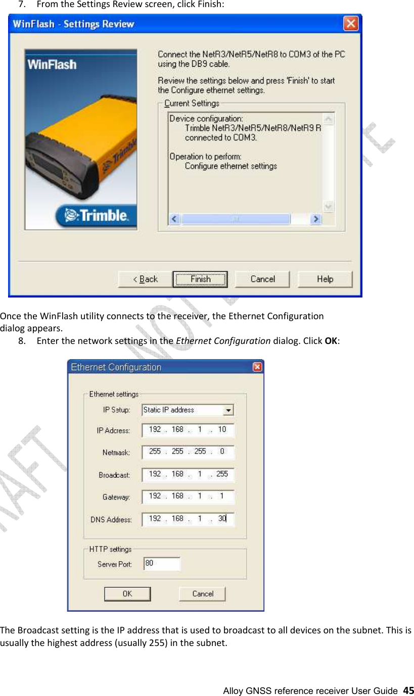
User Manual
Navigation menu
Upload a User Manual
Namespaces
Wiki Guide
HTML
PDF
Info
Views
User Manual
Discussion / Help
Navigation


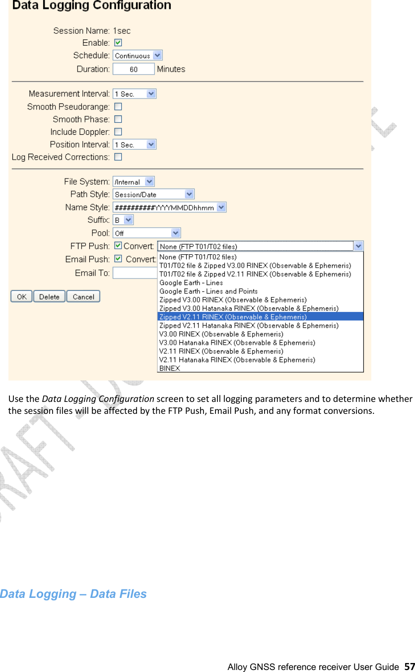
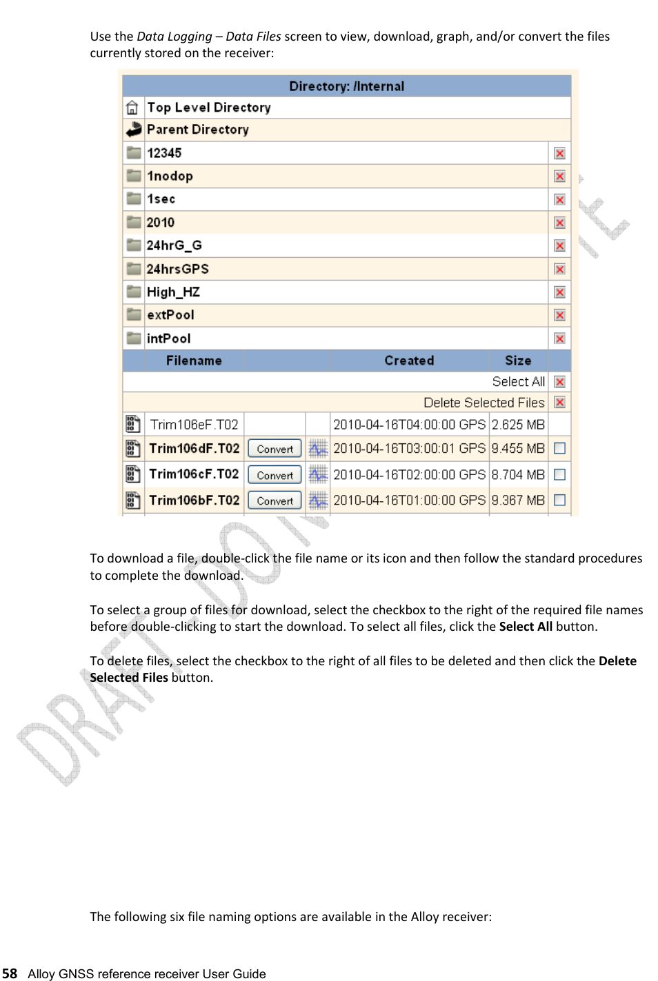
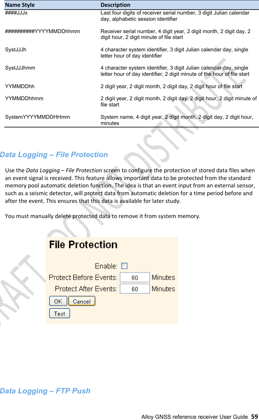
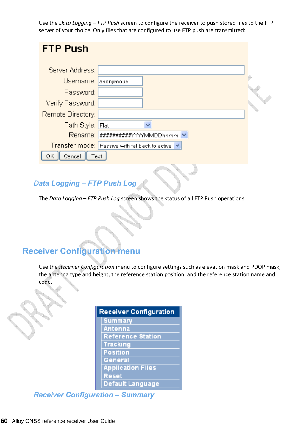
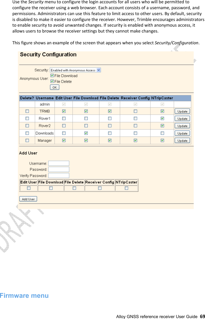
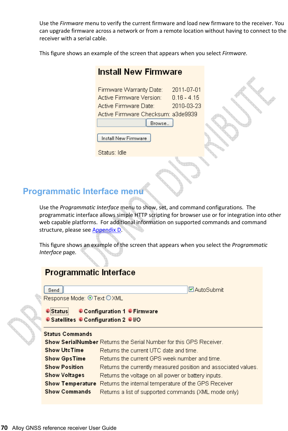


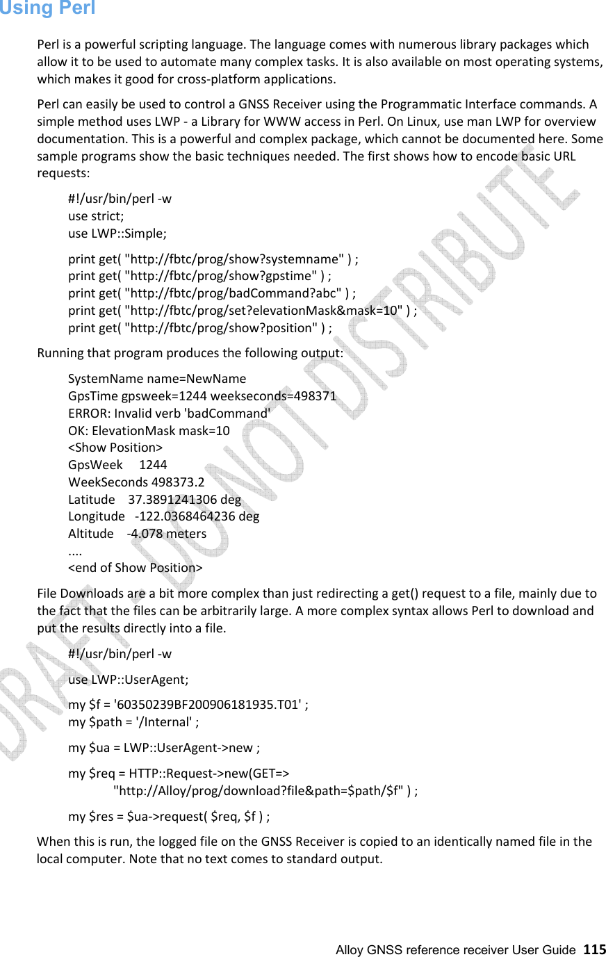
![116 Alloy GNSS reference receiver User Guide File uploads use a similar technique. #!/usr/bin/perl -w use strict ; use HTTP::Request::Common qw(POST) ; use LWP::UserAgent ; print "OKAY\n" ; my $fname = '/tmp/fina_V401.timg' ; my $ua = LWP::UserAgent->new ; my $command = 'http://fbtc/prog/Upload?FirmwareFile' ; my $response = $ua->request( POST( $command , Content_Type => 'form-data', Content => [ 'firmwareFile' => [ $fname ] ] ) ) ; print $response->content ; Running that program produces OK: Failsafe Firmware Installation Started. Other techniques It is quite feasible to use other methods to transmit the Programmatic Commands to the target system. For example one could write C or C++ programs to directly open socket connections to the GNSS Receiver and directly transmit the requests over those channels. This is moderately advanced programming and the details are beyond the scope of this document.](https://usermanual.wiki/Trimble/10950/User-Guide-3640573-Page-116.png)