Trimble 50158-R8 GPS Receiver with integrated GSM and BT User Manual Trimble R7 R8 GPS Receiver User Guide
Trimble Navigation Ltd GPS Receiver with integrated GSM and BT Trimble R7 R8 GPS Receiver User Guide
UserManual.wiki
>
Trimble
>
50158 R8 User Manual
User Manual
Navigation menu
Upload a User Manual
Namespaces
Wiki Guide
HTML
PDF
Info
Views
User Manual
Discussion / Help
Navigation


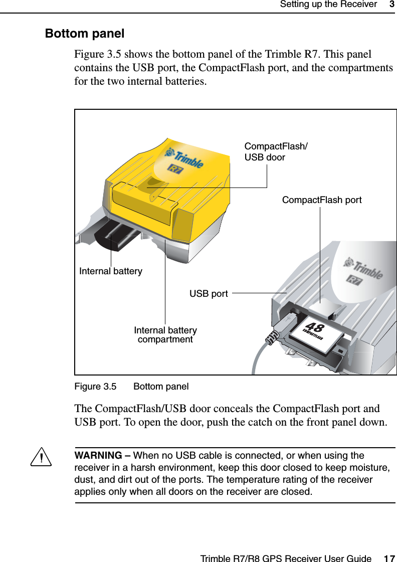
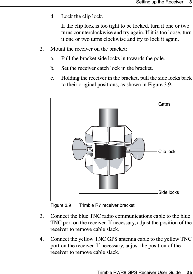
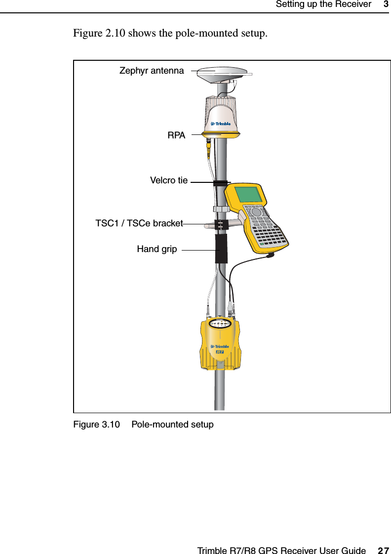
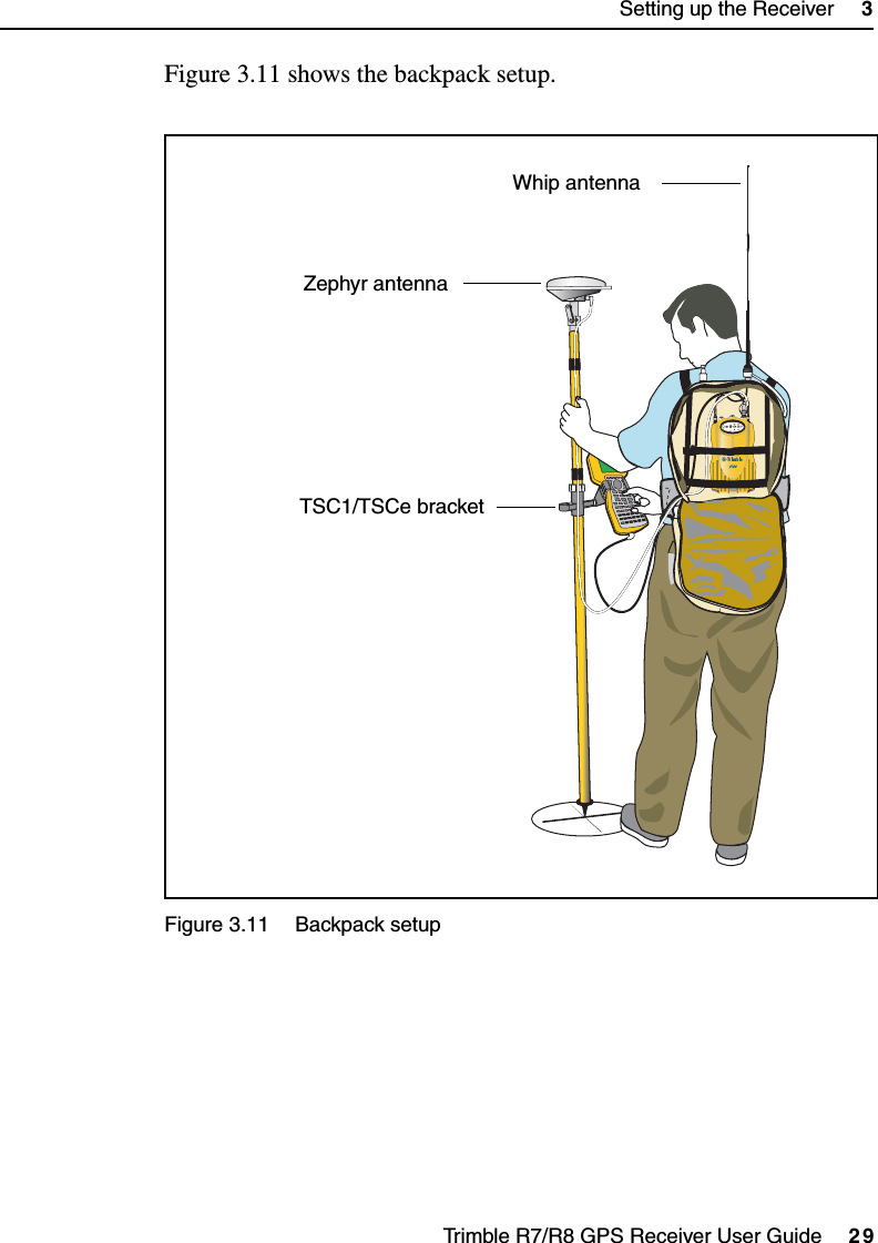
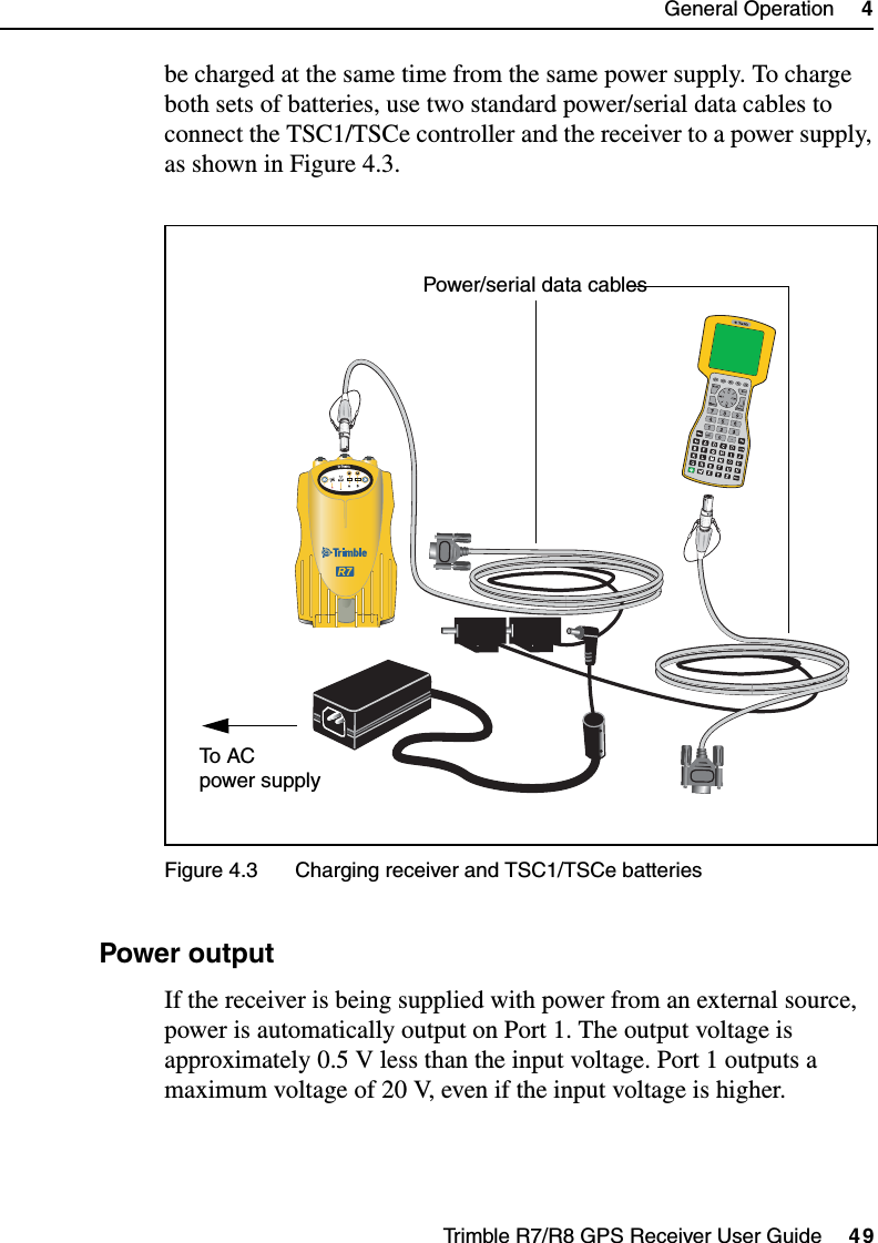

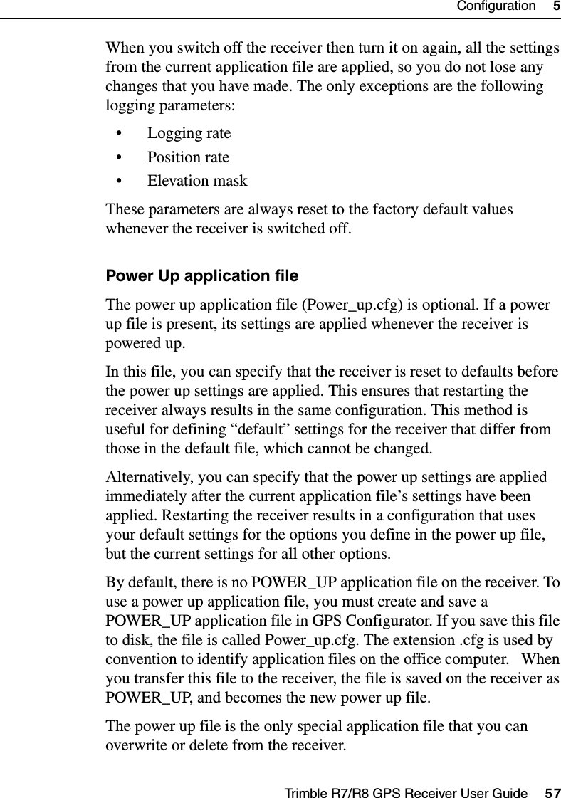
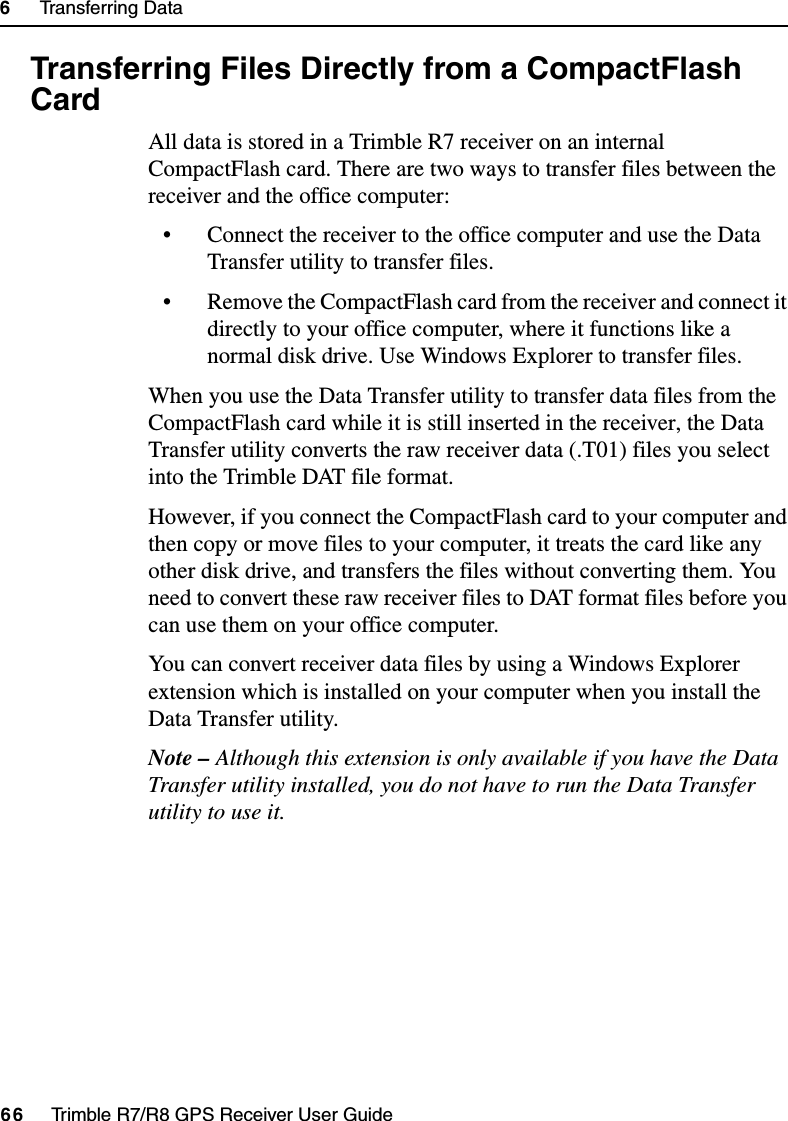


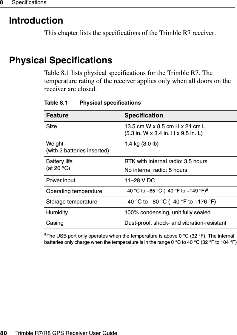
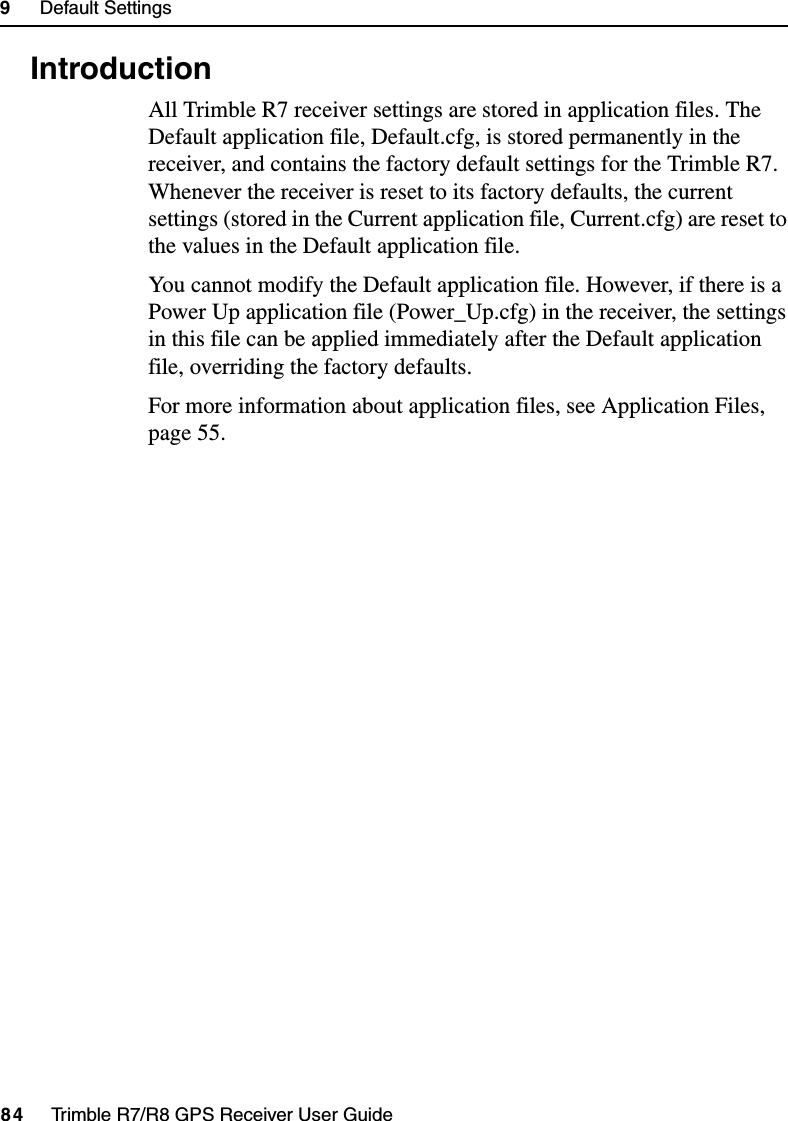
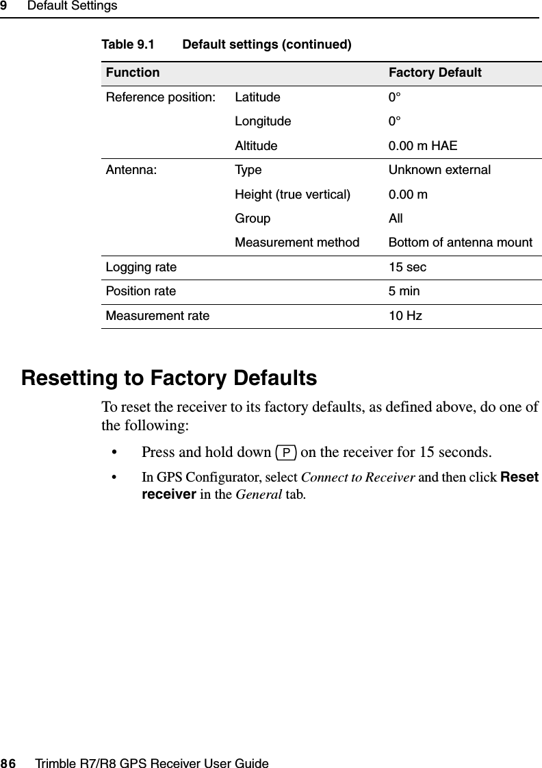
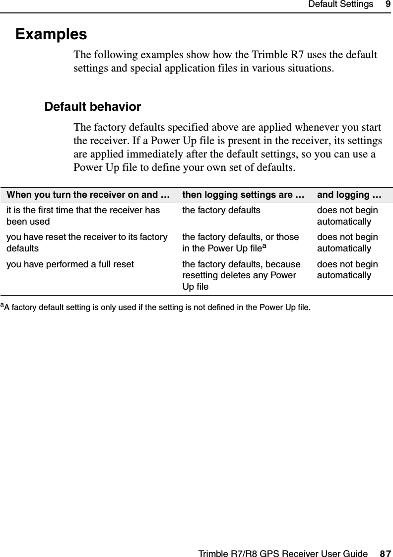
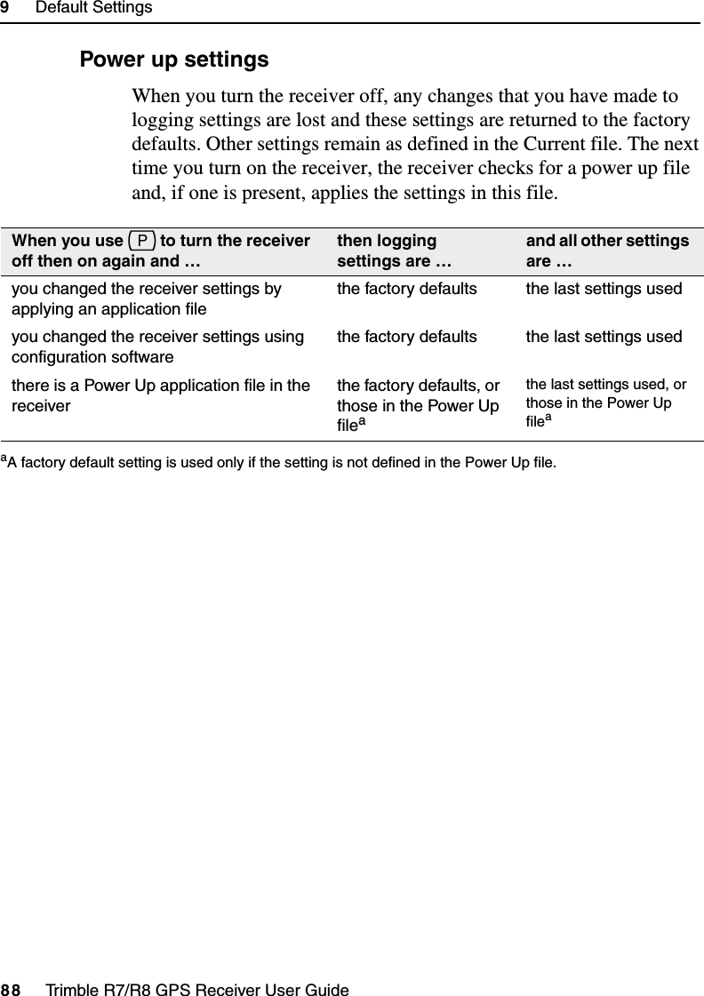
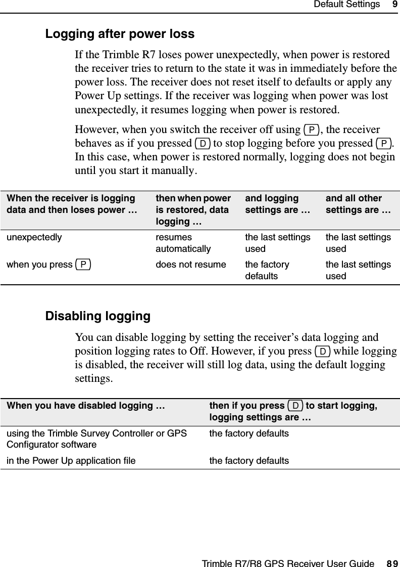
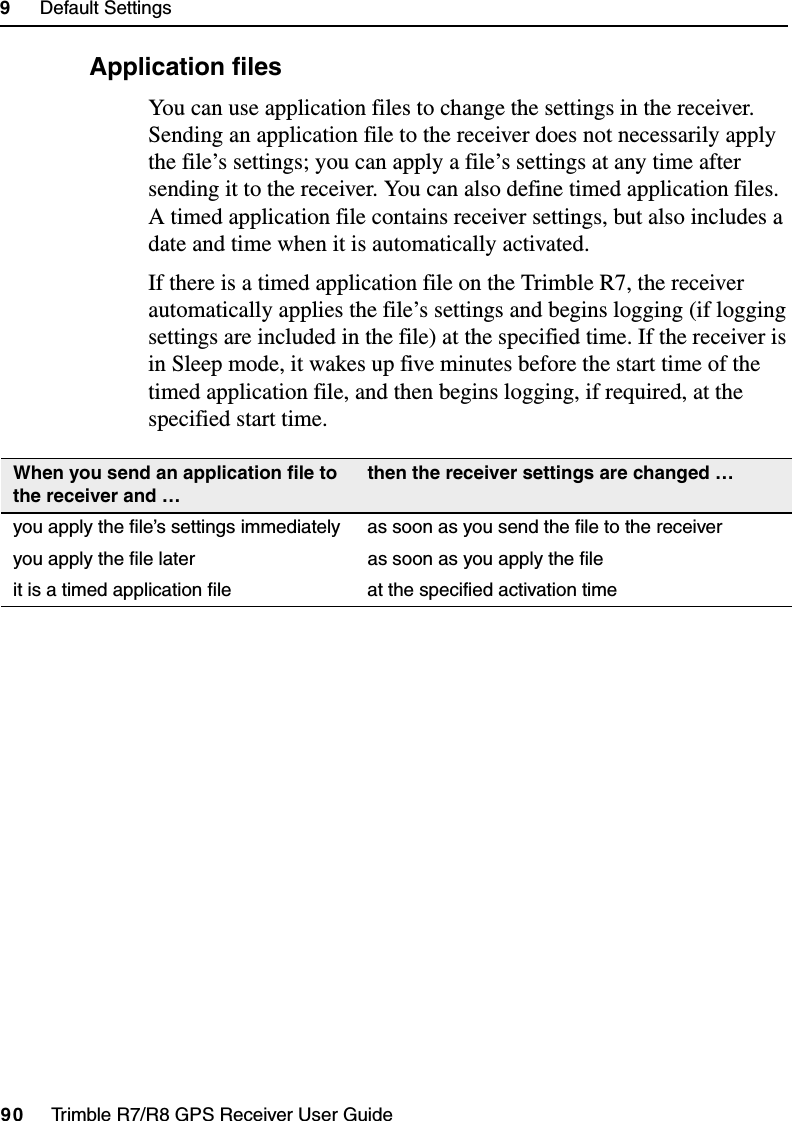
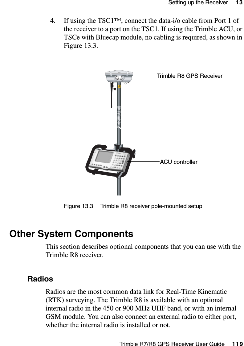
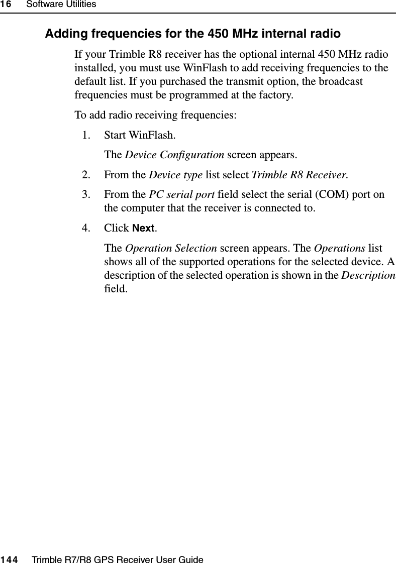
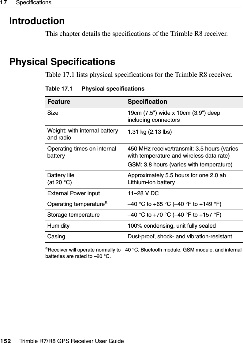
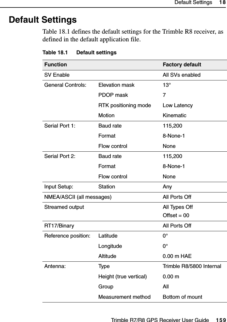
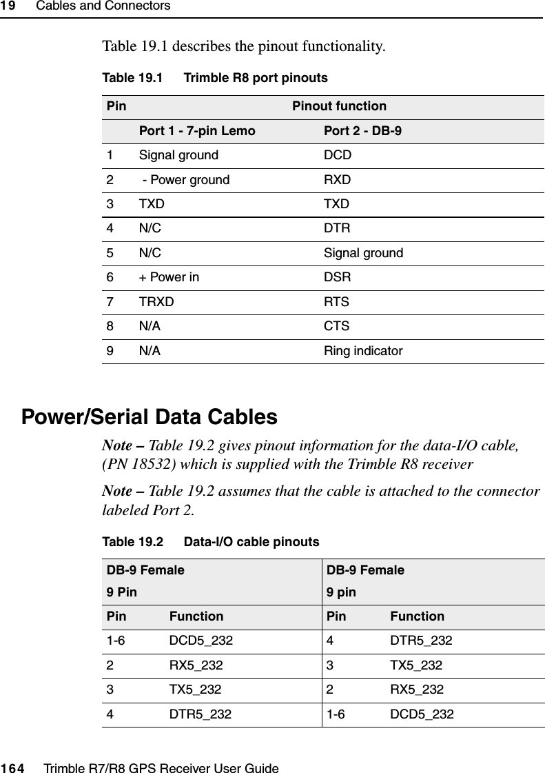
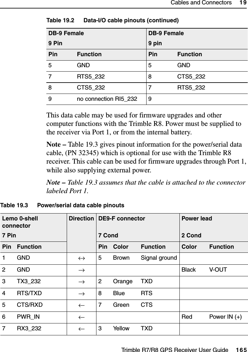
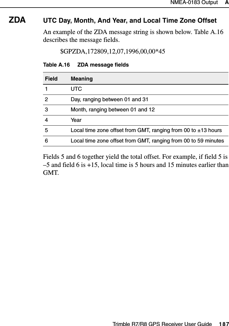
![Trimble R7/R8 GPS Receiver User Guide 85Default Settings 9Trimble R7 Operation9.2 Default SettingsTable 9.1 shows the default settings for the Trimble R7 receiver, as defined in the default application file.Table 9.1 Default settingsFunction Factory DefaultSV Enable All SVs enabledGeneral Controls: Elevation mask 13°PDOP mask 7RTK positioning mode Low LatencyMotion KinematicPower Output 3 Disabled1PPS time tags OffASCII time tags OffSerial Port 1: Baud rate 38400Format 8-None-1Flow control NoneSerial Port 2: Baud rate 38400Format 8-None-1Serial Port 3: Baud rate 38400Format 8-None-1Flow control NoneInput Setup: Station AnyNMEA/ASCII (all messages) All Ports OffStreamed output All Types OffOffset = 00RT17/Binary All Ports OffCMR output [Static] CMR: cref ID 0000RTCM output RTCM: Type 1 ID 0000](https://usermanual.wiki/Trimble/50158-R8/User-Guide-443789-Page-97.png)